Adder ALIF4021R Manual
Læs nedenfor 📖 manual på dansk for Adder ALIF4021R (164 sider) i kategorien Skifte. Denne guide var nyttig for 19 personer og blev bedømt med 4.5 stjerner i gennemsnit af 2 brugere
Side 1/164

ADDERLink™ INFINITY 4000
User Guide
Experts in
Connectivity
Solutions


INSTALLATION
1
CONFIGURATIONOPERATION
FURTHER
INFORMATION
INDEX
Introduction
Welcome 2 ................................................................................................................
Linking 2 ...............................................................................................................
Technical Specications ................................................................................. 3
ALIF4000 unit features ........................................................................................4
Supplied items ....................................................................................................... 5
Optional extras .....................................................................................................6
Installation
Connections ..........................................................................................................7
Mounting 7 ................................................................................................................
TX video links ................................................................................................. 8
TX audio links ................................................................................................. 8
TX USB links ...................................................................................................9
TX AUX (serial) port ....................................................................................9
TX power in 10 ..................................................................................................
TX/RX high speed links ..............................................................................11
RX video display ...........................................................................................12
RX microphone & speakers .......................................................................12
RX USB devices ............................................................................................13
RX power in 14 ..................................................................................................
Conguration
ALIF4000 conguration via web pages ..........................................................15
Performing a manual factory reset .................................................................16
Operation
Front panel indications ...................................................................................... 17
Further information
Getting assistance ..............................................................................................18
Appendix A - Conguration pages .................................................................19
Appendix B - Tips for success when networking ALIF units ....................34
Appendix C - Troubleshooting ........................................................................36
Appendix D - Glossary .....................................................................................38
Appendix E - Null modem cable pinout .......................................................41
Appendix F - Fiber modules and cables ........................................................42
Appendix G - Using the optional ALIF4000 rack shelf .............................43
Appendix H - Open source licenses ..............................................................44
Index
Contents


INSTALLATION
2
CONFIGURATIONOPERATION
FURTHER
INFORMATION
INDEX
Introduction
WELCOME
Thank you for choosing the ADDERLink™ INFINITY 4000 (aka ALIF4000) high capacity
extenders. The ALIF4000 range offers dual-head 4K, audio and USB delivered over a
single ber connection. Pixel-perfect color, accurate picture quality at 4K60 and USB2.0
with fast switching.
Product in brief
• Dual-head 4K, video, audio and USB over a single ber connection,
• Pixel-perfect, color accuracy at 4K60,
• Bi-directional analog audio,
• Adder’s USB True Emulation for fast switching,
• Backwards compatibility with existing ALIF range,
• Plug and play.
ALIF4000 RX
10 Gigabit
Switching
ALIF4000 RX
ALIF4000 RX
ALIF4000 TX
ALIF4000 RX
ALIF4000 TX
IMPORTANT: When using AIM to congure
ALIF units, it is vital that all units that you wish
to locate and control are set to their factory
default settings. Otherwise they will not be
located by the AIM server. If necessary, perform
a manual factory reset on each ALIF unit.
Note: If you are using one or more ALIF4000
transmitters within an installation managed by
an AIM server, the AIM server must be running
rmware version or above.4.9
Linking
ALIF4000 units can be linked in two mains ways: Direct or Networked.
Direct linking
Where ALIF4000 transmitters and receivers are directly linked to each other, very
little conguration action is required, provided that they both have their factory default
settings in place - just link them together. If the standard settings have been changed in a
previous installation, you merely need to perform a manual factory reset on each unit.
Networked linking
Where ALIF4000 units are connected via networked links, you can either congure them
individually, or congure them collectively using an AIM server:
• ConguringnetworkedALIFunitsindividually - You need to specify the network
addresses of the ALIF4000 units so that they can locate each other. This can be done
using via OSD on the console connected to the RX unit by pressing CTRL + + ALT C.
• ConguringnetworkedALIFunitscollectively - The ADDER Link™ INFINITY
Management (AIM) server allows you to congure, control and coordinate any number
of ALIF transmitters and receivers from a single application.
Safety
Please refer to the safety booklet provided in the box before use of this product.


INSTALLATION
5
CONFIGURATIONOPERATION
FURTHER
INFORMATION
INDEX
Add erLink
4000
TRANSMIT
2
3
1
4
SUPPLIEDITEMS
2xAudiocable2m
(3.5mm stereo jacks)
ALIF4000TXpackage
ALIF4000RXpackage
Informationwallet
containing:
Four self-adhesive rubber feet
Quick start guide
Safety document
Informationwallet
containing:
Four self-adhesive rubber feet
Quick start guide
Safety document
ALIF4000TXunit
ALIF4000RXunit
2xUSBcable2m(typeAtoB)
Part number: VSC24
Power adapter with
locking connector
andcountry-specic
power cord
Add erLink
4000
2
3
1
RECEIVE
Power adapter with
locking connector
andcountry-specic
power cord
2x Display port
videocable2m


INSTALLATION
6
CONFIGURATIONOPERATION
FURTHER
INFORMATION
INDEX
OPTIONALEXTRAS
Dual unit 19” (1U) rack-mount shelf
Part number: RMK12
Audiocable2m
(3.5mm stereo jacks)
Part number: VSC22
USBcable2m(typeAtoB)
Part number: VSC24
10GbEsinglemodeberSFPmodule
Part number: SFP-SM-LC-10G
10GbEmultimodeberSFPmodule
Part number: SFP-MM-LC-10G
Please refer to the table in Appendix F for
information about ber modules and cables.
Replacement power adapter
with locking connector
Part number: PSU-IEC-12VDC-5A
Country-specicpowercords
CAB-IEC-AUS (Australia)
CAB-IEC-EURO (Central Europe)
CAB-IEC-UK (United Kingdom)
CAB-IEC-USA (United States)
CAB-IEC-JP (Japan)
CAB-IEC-CN (China)
Displayportvideocable2m
Part number: VSCD10A


7
INSTALLATIONCONFIGURATIONOPERATION
FURTHER
INFORMATION
INDEX
MOUNTING
Please see Appendix G for details about mounting options for the ALIF units.
Installation
CONNECTIONS
Installation involves linking the ALIF4000 TX unit to various ports on the host computer,
while the ALIF4000 RX unit is attached to your peripherals (collectively known as the
Console:
Click a connection to see details
IMPORTANT: When using an ADDERLink™ INFINITY Management box to
congure ALIF units, it is vital that all ALIF units that you wish to locate and control
are set to their factory default settings. Otherwise they will not be located by the
AIM server. If necessary, perform a factory reset on each ALIF unit.
Please also see Appendix B - Tips for success when networking ALIF units
ALIF4000 RXALIF4000 TX
VIDEO
LINK
page 8
VIDEO
DISPLAY
page 12
FIBRE LINK
page 11
USB
DEVICES
page 13
USB
LINK
page 9
AUDIO
LINKS
page 8
SERIAL
LINK
page 9 POWER
IN
page 10
POWER
IN
page 14
MIC &
SPEAKERS
page 12


8
INSTALLATIONCONFIGURATIONOPERATION
FURTHER
INFORMATION
INDEX
1 2
optical
OUT
AUX
IN
1 2
1 2
optical
IN
TXvideolinks
The TX unit supports two display port
connections, each up to 4K UHD (3840 x
2160) or DCI (4096 x2160), with refresh
rates up to 60Hz.
2 Connect the plug at the other end of the cable(s) to the
corresponding video output socket(s) of the host computer.
ALIF4000 RX
ALIF4000 TX
VIDEO
LINK
LINK
USB
LINK
AUDIO
LINKS
POWER
IN
SERIAL
LINK
Tomakeavideolink
1 Connect your digital video link cable(s) to the display port
socket(s) on the TX unit rear panel:
To primary
videooutput
port
To secondary
videooutput
port
TXaudiolinks
The TX unit supports two way stereo
digital sound so that you can use a remote
microphone as well as speakers.
2 [Where a microphone is to be used]: Connect a second audio link cable
between the socket on the TX unit rear panel and the Line In OUT
socket of the host computer.
To make audio links
1 Connect an audio link cable between the socket on the TX opticalIN
unit rear panel and the speaker output socket of the host computer.
Speaker link from
host computer
Microphone link
to host computer
ALIF4000 RX
ALIF4000 TX
VIDEO
LINK
LINK
USB
LINK
AUDIO
LINKS
POWER
IN
SERIAL
LINK


9
INSTALLATIONCONFIGURATIONOPERATION
FURTHER
INFORMATION
INDEX
1
1 2
12V
3A
4
TXUSBlinks
The TX unit has two USB type B sockets
on the rear panel. Socket 2 is reserved for
future use.
2 Connect the type A connector of the cable to USB socket 1
on the host computer.
Note: USB socket 2 is reserved for future use.
USB link from
host computer
To make a USB link
1 Connect the type B connector of the supplied USB cable to the
USB port on the TX unit rear panel.
TXAUX(serial)port
The AUX port is an RS232 serial port
that allows extension of RS232 signals up
to a baud rate of 115200. The port has
software ow control, but no hardware
ow control.
ToconnecttheAUXport
1 Connect a suitable serial ‘null-modem’ cable (see Appendix F for pin-out) between a
vacant serial port on your computer and the AUX port on the right hand side of the
ALIF rear panel.
2
optical
OUT AUX
IN
Serial (null-modem) link
from your computer
ALIF4000 RX
ALIF4000 TX
VIDEO
LINK
LINK
USB
LINK
AUDIO
LINKS
POWER
IN
SERIAL
LINK
ALIF4000 RX
ALIF4000 TX
VIDEO
LINK
LINK
USB
LINK
AUDIO
LINKS
POWER
IN
SERIAL
LINK
Note: Serial port function not
available in initial release. To be
added in later revisions.


10
INSTALLATIONCONFIGURATIONOPERATION
FURTHER
INFORMATION
INDEX
1
12V
3A
1 2
12V
3A
44
TXpowerin
Each unit is supplied with a power
adapter and country-specic power
cord. The supplied power adapter uses
a locking-type plug to help prevent
accidental disconnection; please follow
the instructions shown on the right
when disconnecting a power adapter.
To connect the power adapter
1 Attach the output plug of the supplied
power adapter to the power input
socket on the left side of the rear
panel. As you insert the plug, pull back
slightly on the outer body to assist
the locking mechanism until the plug
is fully inserted.
2 Insert the IEC connector of the supplied country-specic
power cord to the socket of the power adapter.
3 Connect the power cord to a nearby mains supply socket.
To disconnect the power adapter
1 Isolate the power adapter from the mains supply.
2 Grasp the outer body of the power adapter plug
where it connects with the node.
3 Gently pull the body of the outer plug away from
the node. As the body of the plug slides back, it will
release from the socket and you can fully withdraw
the whole plug.
IMPORTANT:Pleasereadandadheretotheelectricalsafetyinformation
givenwithintheSafetyinformationbookletprovidedwiththisproduct.In
particular, do not use an unearthed power socket or extension cable.
Note: The unit and the power adapter generate heat when in operation and will become
warm to the touch. Do not enclose them or place them in locations where air cannot circulate
to cool the equipment. Do not operate the equipment in ambient temperatures exceeding
40 degrees Centigrade. Do not place the products in contact with equipment whose surface
temperature exceeds 40 degrees Centigrade.
Fromthe
power adapter
Gentlypullbacktheplugouter
body to release the lock
ALIF4000 RX
ALIF4000 TX
VIDEO
LINK
LINK
USB
LINK
AUDIO
LINKS
POWER
IN
SERIAL
LINK


11
INSTALLATIONCONFIGURATIONOPERATION
FURTHER
INFORMATION
INDEX
2 Make your connection(s) between
the chosen SFP module and either
the other ALIF4000 unit or to a
suitable network ber switch:
Connect the transmit and receive ber optic links to the sockets on the Fiber
Channel SFP module. Then close the latch over the link connectors to lock them into
place.
Note: SFP-SM-LC-10G modules require OS1 or OS2 single mode ber.
SFP-MM-LC-10G modules require OM1, OM2, OM3 or OM4 multi-mode ber.
Transmit and
receiveberlinks
1 Insert the appropriate optional SFP
module (SFP-MM-LC-10G or SFP-
SM-LC-10G) into socket 3 located on
the front panel of the TX unit...
LINK
LINK
ALIF4000 TX
VIDEO
LINK
USB
LINK
AUDIO
LINKS
POWER
IN
SERIAL
LINK
ALIF4000 RX
VIDEO
DISPLAY
USB
DEVICES
MIC &
SPEAKERS
POWER
IN
4 0 0 0
TRANSMIT
2
34
TX/RXhigh speed links
ALIF4000 units can be either connected directly to each other or via a high speed
(10GB) network. Currently, the connections must be Fiber Channel over Ethernet
(FCoE). A single ber link (using SFP port 3) is sufcient to provide full 4K operation
between ALIF4000 units. Where required, a second ber link can be used (via SFP port 4)
to provide link redundancy.
TolinkALIF4000unitsviaber
1 2 3 4
4 0 0 0
TRANSMIT
2
34
...and the rear panel of the RX unit:


12
INSTALLATIONCONFIGURATIONOPERATION
FURTHER
INFORMATION
INDEX
1 2
4
5
optical
OUT
RXvideodisplay
The RX unit supports two video
displays, each up to 4K UHD (3840
x 2160) or DCI (4096 x2160), with
refresh rates up to 60Hz.
2 If required, connect the lead from the second video display to the
display port socket marked ‘2’ on the RX unit rear panel.
Toconnectvideodisplays
1 Connect the lead from the primary video display to the display port
socket marked ‘ ’ on the RX unit rear panel:1
To
secondary
videodisplay
To
primary
video
display
ALIF4000 TX
LINK ALIF4000 RX
VIDEO
DISPLAY
USB
DEVICES
MIC &
SPEAKERS
POWER
IN
RXmicrophone&speakers
The RX unit can support a
microphone as well as speakers
providing the necessary connections
have been made between the TX unit
and the host computer.
To connect a microphone (or line in) and/or speakers
ALIF4000 TX
LINK ALIF4000 RX
VIDEO
DISPLAY
USB
DEVICES
MIC &
SPEAKERS
POWER
IN
AdderLink
4 0
2
3
1 Connect the lead from a
mono microphone to the
3.5mm socket labeled on
the front panel.
2 Connect the lead from
stereo speakers to the
3.5mm socket labeled on
the front panel.


13
INSTALLATIONCONFIGURATIONOPERATION
FURTHER
INFORMATION
INDEX
RXUSBdevices
The ALIF RX unit has ve USB ports
(three on the front panel and two on
the rear) to which peripherals may be
connected.
Note: USB socket 1 on the front panel is
reserved for future use.
To connect more than four peripherals,
one or more USB hubs may be used. The
total current that may be drawn from
the USB ports is 1.2A, which should be sufcient for a keyboard, mouse (no more than
100mA each) and any two other devices (500mA maximum each). If more power for
USB devices is required, use a powered USB hub.
ALIF4000 TX
LINK ALIF4000 RX
VIDEO
DISPLAY
USB
DEVICES
MIC &
SPEAKERS
POWER
IN
4 0 0 0
RE CE IV E
2
3
1
1
4
5
2V
A
ToconnectUSBdevices
1 Connect the lead from the device to any
of the USB sockets on the front and rear
panels of the RX unit (except socket 1).
Note: USB socket 1 is
reserved for future use.


14
INSTALLATIONCONFIGURATIONOPERATION
FURTHER
INFORMATION
INDEX
ALIF4000 TX
LINK ALIF4000 RX
VIDEO
DISPLAY
USB
DEVICES
MIC &
SPEAKERS
POWER
IN
1
12V
3A
RXpowerin
Each unit is supplied with a power
adapter and country-specic power
cord. The supplied power adapter uses
a locking-type plug to help prevent
accidental disconnection; please follow
the instructions shown on the right
when disconnecting a power adapter.
To connect the power adapter
1 Attach the output plug of the supplied
power adapter to the power input
socket on the left side of the rear
panel. As you insert the plug, pull back
slightly on the outer body to assist
the locking mechanism until the plug
is fully inserted.
2 Insert the IEC connector of the supplied country-specic power cord to the socket of
the power adapter.
3 Connect the power cord to a nearby mains supply socket.
To disconnect the power adapter
1 Isolate the power adapter from the mains supply.
2 Grasp the outer body of the power adapter plug
where it connects with the node.
3 Gently pull the body of the outer plug away from
the node. As the body of the plug slides back, it will
release from the socket and you can fully withdraw
the whole plug.
IMPORTANT:Pleasereadandadheretotheelectricalsafetyinformation
givenwithintheSafetyinformationbookletprovidedwiththisproduct.In
particular, do not use an unearthed power socket or extension cable.
Note: The unit and the power adapter generate heat when in operation and will become
warm to the touch. Do not enclose them or place them in locations where air cannot circulate
to cool the equipment. Do not operate the equipment in ambient temperatures exceeding
40 degrees Centigrade. Do not place the products in contact with equipment whose surface
temperature exceeds 40 degrees Centigrade.
Fromthe
power adapter
Gentlypullbacktheplugouter
body to release the lock
4
5
12V
3A


15
INSTALLATIONCONFIGURATIONOPERATION
FURTHER
INFORMATION
INDEX
Conguration
ALIF4000CONFIGURATIONVIAWEBPAGES
Each ALIF4000 unit hosts its own internal set of web pages which contain all
conguration details and settings. You will need to use a computer connected to the
same network as each ALIF4000 unit to access the web pages. Additionally, on the
console attached to the ALIF4000 RX unit, you can access its conguration details via the
On Screen Display (OSD) by pressing CTRL + + ALT C.
TocongureALIF4000unitsviatheirwebpages
Run a web browser on your computer and enter the IP address of the required
ALIF4000 unit:
The default addresses (when using SFP port ) are 3TX: 169.254.1.33
RX: 169.254.1.32
The default addresses (if using SFP port ) are 4TX: 169.254.1.43
RX: 169.254.1.42
If the IP address of a unit has been changed, you can either:
• Discover the unit’s main IP address by pressing the small
button on the front panel next to the OLED screen to
reveal the value for IP Address 3 (or IP Address 4).
• Alternatively, providing it is appropriate to do so, perform a manual factory reset (see
next page) to restore the default address.
The opening page should be displayed:
IP Address 3
169.254.1.33
For explanations of the options within each page, please see Appendix A.


17
INSTALLATIONCONFIGURATIONOPERATION
FURTHER
INFORMATION
INDEX
In operation, many ALIF4000 installations require no intervention once congured. The
TX and RX units take care of all connection control behind the scenes so that you can
continue to work unhindered.
FRONTPANELINDICATIONS
The front panel of each ALIF4000 unit features an OLED information screen plus a single
indicator capable of producing numerous color and ash patterns to provide a useful
guide to operation.
OLED screen
Press and release the button to wake the OLED screen and begin showing information.
Press the button repeatedly to change between subjects:
Operation
Indicatorcolorandashpatterns
The single front panel indicator uses varying color and ashing patterns to signal key
status :
Off No power.
Green All services present as compared to the conguration required.
Amber Running but video, USB or network link missing (or not connected
to another ALIF unit).
Red Booting before processor loaded or failed.
Blue Factory reset mode active.
Red/green ash Booting into factory recovery mode.
Red/blue ash Upgrade mode active.
Fast green ash Identify mode active.
IP Address 3
169.254.1.33
Video Source 1
1920x1080p@60.00
MAC Address 4
000F5802E7A7
Serial No.
1904A0000164
Software Version
1.00A
BaseIPaddress
Internalrmwareversion
Videosource
MACaddresses
Serial number


19
INSTALLATIONCONFIGURATIONOPERATION
FURTHER
INFORMATION
INDEX
APPENDIXA-Congurationpages
This section covers the web page conguration for the ALIF4000 units:
• TX - General Information
• TX - UI Settings
• TX - Ports
• TX - Network
• TX - Diagnostics and Statistics
• TX - System
• RX - General Information
• RX - UI Settings
• RX - Presets
• RX - Ports
• RX - Network
• RX - Diagnostics and Statistics
• RX - System

21
INSTALLATIONCONFIGURATIONOPERATION
FURTHER
INFORMATION
INDEX
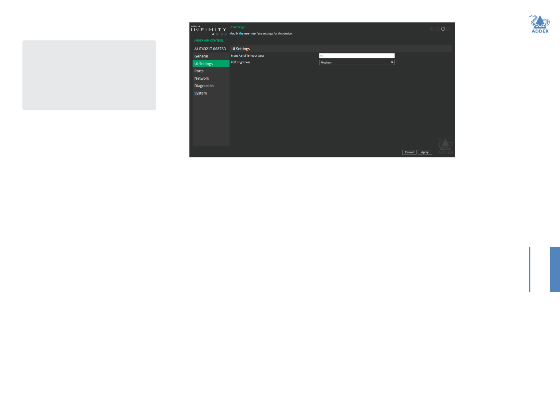
TX-UISettings
UISettings
FrontPanelTimeout - Determines the period of inactivity that should
elapse before the front panel display should return to a blank state.
LED brightness - Determines the brightness of the front panel LED
indicator.
To get here
1 Connect a computer to the same network as the TX unit.
2 Run a web browser and enter the IP address of the TX
unit: (this is the default address when http://169.254.1.33
using SFP port 3). If you are using SFP port 4 then the
default address will be http://169.254.1.43
If the IP address is unknown, press the small button on the
front panel next to the OLED screen to reveal the value
for IP Address 3 (or IP Address 4) and use that address.
3 Click the UISettings link.


23
INSTALLATIONCONFIGURATIONOPERATION
FURTHER
INFORMATION
INDEX
NetworkInformation
This page provides numerous network details for each of the installed
ports on the TX unit.
Socket - Details each operational network socket. Sockets 3 and 4 are
determined by the SFP modules plugged into them.
MACAddress - Displays the unique, xed hardware identication
number for each port.
Link Up - Indicates whether the link state of this network interface is
up. This should be the case if the device is connected to a functioning
network.
IPAddress - The IP address of this network interface. This is not
congurable, the device can function in a network zero-cong state
which does not require the setting of a static IP address.
Netmask - The netmask of this network interface. This is not
congurable, the device can function in a network zero-cong state
which does not require the setting of a static netmask.
Gateway - The gateway address of this network interface. This is not
congurable, the device can function in a network zero-cong state
which does not require the setting of a static gateway.
DHCP Enabled - When ticked, the corresponding port will derive its IP
Address, Netmask and Gateway details from the DHCP server listed in
the eld below.
DHCPServerAddress - Lists the address of a valid DHCP server
(which can be the AIM server) to be used when the DHCP Enabled
checkbox above is ticked.
Route of Last Resort - In a multi interface device such as this, the
interface which is ticked will be used as the default whenever it is unclear
which interface should be used for network trafc. This is determined via
the AIM server.
TX-Network
Routing Table - Click on ‘Details’ to show the routing table entries
corresponding to this network interface. In it are the destination address,
gateway and netmask for the routes to particular network destinations.
DNSServers - List of DNS server addresses obtained via DHCP.
NTP Enabled - When ticked, the unit will derive its time and date
information from a suitable NTP server.
NTPServers - Lists NTP server addresses obtained via DHCP.
NTPKeyID - The ID of the key used for secure NTP.
NTPKeyValue - The value of the key used for secure NTP as a
hexadecimal string.
AIMEnabled - Indicates whether server management is enabled for
this device.
AIMServers - Lists management server addresses that have been
manually congured.
To get here
1 Connect a computer to the same network as the TX unit.
2 Run a web browser and enter the IP address of the TX
unit: (this is the default address when http://169.254.1.33
using SFP port 3). If you are using SFP port 4 then the
default address will be http://169.254.1.43
If the IP address is unknown, press the small button on the
front panel next to the OLED screen to reveal the value
for IP Address 3 (or IP Address 4) and use that address.
3 Click the Network link.

24
INSTALLATIONCONFIGURATIONOPERATION
FURTHER
INFORMATION
INDEX
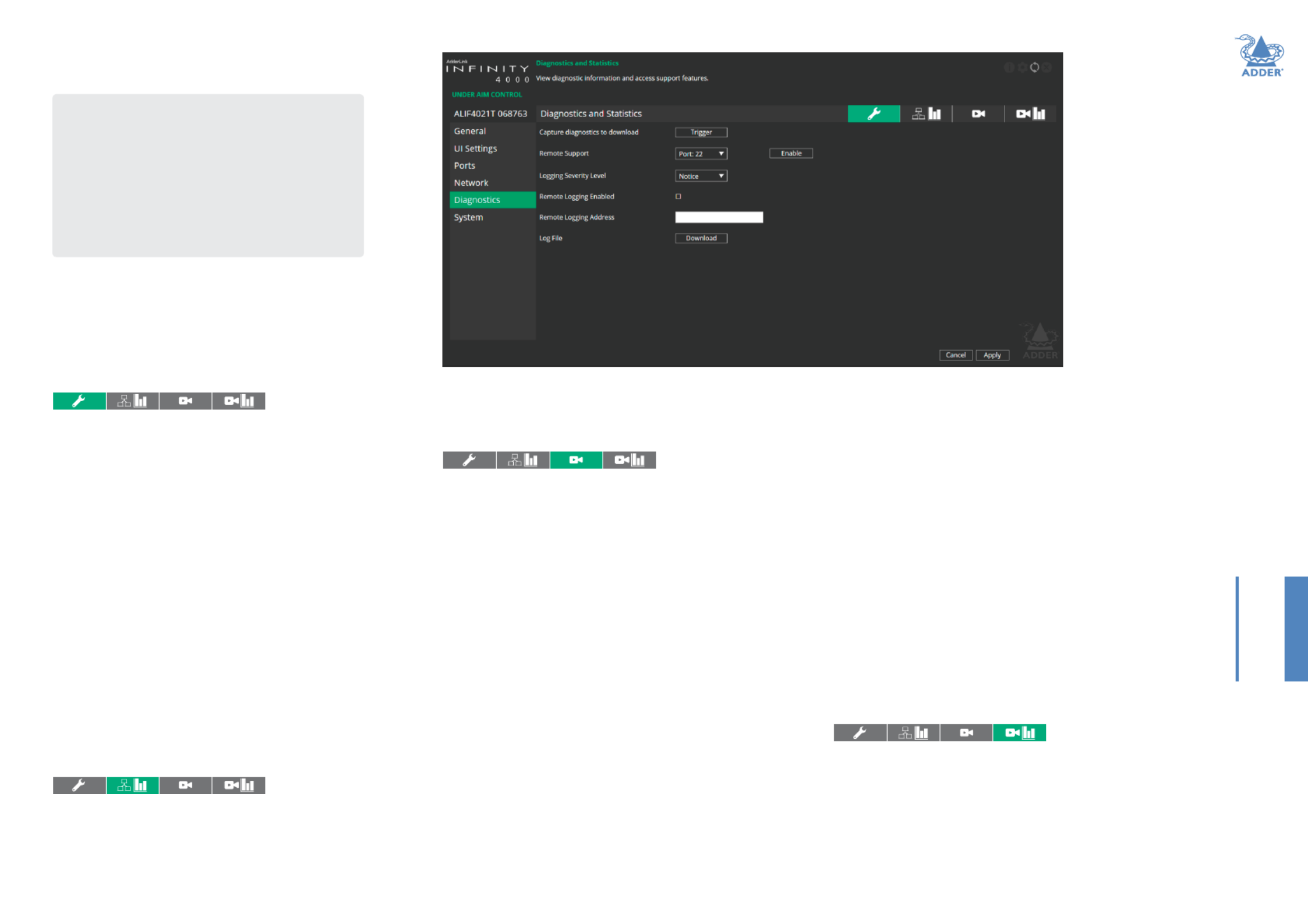
Log Settings
This page provides numerous key diagnostic log settings.
Capture diagnostics to download - Request generation of a
diagnostics dump le. This will then be downloaded by the host
computer’s browser, this is an encrypted diagnostics le which can be
used by technical support to diagnose and x an issue.
Remote Support - When using the Adder remote server, this option
determines which port will be used. Multiple options are offered in case
one or more ports are blocked by your rewall.
LoggingSeverityLevel - Denes the level of messages that will be
logged (according to RFC5424). Level 5 (Notice: normal but signicant
condition) is the default setting; ALIF4000 supports levels 1 to 7. Choosing
levels 6 will cause larger numbers of lesser (Informational) (Debug) or 7
events to also be logged, with a potential impact to overall performance.
These levels should only be used if working with the support team to
diagnose a specic issue.
Remote Logging Enabled - Tick to send log les to the chosen
Remote Logging Address.
RemoteLoggingAddress - Enter a valid IP address for a syslog server
on the local network where status logs can be sent.
LogFile - Click to download the log le to the host computer’s browser.
Network Statistics
This page allows you to view current communication statistics and also
to create graphs in real time.
CaptureandGraphStatistics - When ticked, the page will create a
real time graph plotting Received Bytes alongside Received Packets.
TX-DiagnosticsandStatistics
After Capture and Graph Statistics is enabled, the Show Legend checkbox
will show all other items that can be included on the plot. Click an item
to tick and include it.
VideoPortStatus
This page lists key settings related to the physical video ports, the signal
encoding employed and the data transmitted through them.
Port: Shows the display port sink interface status for each video port.
Connected – Is there a device connected to this video port?
Powered – Is the device connected powered on or not?
Hot-Plug Asserted – Is the TX asserting HotPlug to the device to indicate
the presence of a display to the host computer on this video port?
Link Rate - Data rate speed negotiated with the host computer on this
video port.
Timing Mode – Video signal timing details detected by the TX from the
PC connected on this video port.
Timing Period – Video signal frame period in uSecs.
Pixel Clock – Video pixel clock for the video signal on this port.
Horizontal Resolution – As stated.
Horizontal Sync Start & End – For future use.
Horizontal Frame Length – As stated.
Vertical Resolution – As stated.
Vertical Sync Start & End – For future use.
Vertical Frame Length – As stated.
Timing ags – States the timing method, e.g. Progressive Interlaced or .
Encoding - Shows the video processor status for each video port.
Enabled – Is the video processor running or not?
High Res Single Head mode – Is the video processor running in high-
res single head mode (ie. both processors used to do greater than 4k
resolutions). For future implementation.
Pixel Buffer Full - If ticked, a fault has occurred in processing.
Segments per line... to Segment Compare Enabled - Video processor
encoding setup status for diagnostics purposes only.
Maximum Segment Compare Level Magic Eye – Equivalent to setting on
AIM server. 0 = Off, 1= Magic Eye on.
Segment Refresh Enabled Background Refresh – Equivalent to on AIM
server. Background refresh enabled (ie. 32, 64, etc) then Segment Refresh
Enabled = On.
Segment Refresh Period Background Refresh = Equivalent to on AIM server
when set to a value.
Transmission - Lists various settings relating to the data transmission
used via each video port; such as network teaming, whether the data has
stopped, whether interfaces are enabled and the source and destination
addresses for each video stream.
VideoPortStatistics
This page provides frame and packet counts for both video ports.
DroppedFrames - The number of frames dropped before transmission
on each video port.
Transmitted Packets - The total number of packets output from the
video processor on each video port.
Packets Transmitted - The breakdown of packets transmitted for each
video stream on each video port.
To get here
1 Connect a computer to the same network as the TX unit.
2 Run a web browser and enter the IP address of the TX
unit: (this is the default address when http://169.254.1.33
using SFP port 3). If you are using SFP port 4 then the
default address will be http://169.254.1.43
If the IP address is unknown, press the small button on the
front panel next to the OLED screen to reveal the value
for IP Address 3 (or IP Address 4) and use that address.
3 Click the Diagnostics link.


25
INSTALLATIONCONFIGURATIONOPERATION
FURTHER
INFORMATION
INDEX
Software and System Operations
This page contains various indications and options related to the internal
software of the unit.
Note: The highlighted (and colored) entry is the version of software currently
running.
PreferredSoftwareVersion - The software version the device will
boot into upon a reboot.
RecoverySoftwareVersion - The software version the device will
boot into if placed into recovery mode.
AlternateSoftwareVersion - The other (backup) version of software
the device has available.
RebootDevice - Click the Reboot button to Reboot the device.
Restore Default Settings - Click the Restore button to restore the
device to factory default settings.
TX-System
To get here
1 Connect a computer to the same network as the TX unit.
2 Run a web browser and enter the IP address of the TX
unit: (this is the default address when http://169.254.1.33
using SFP port 3). If you are using SFP port 4 then the
default address will be http://169.254.1.43
If the IP address is unknown, press the small button on the
front panel next to the OLED screen to reveal the value
for IP Address 3 (or IP Address 4) and use that address.
3 Click the System link.

26
INSTALLATIONCONFIGURATIONOPERATION
FURTHER
INFORMATION
INDEX
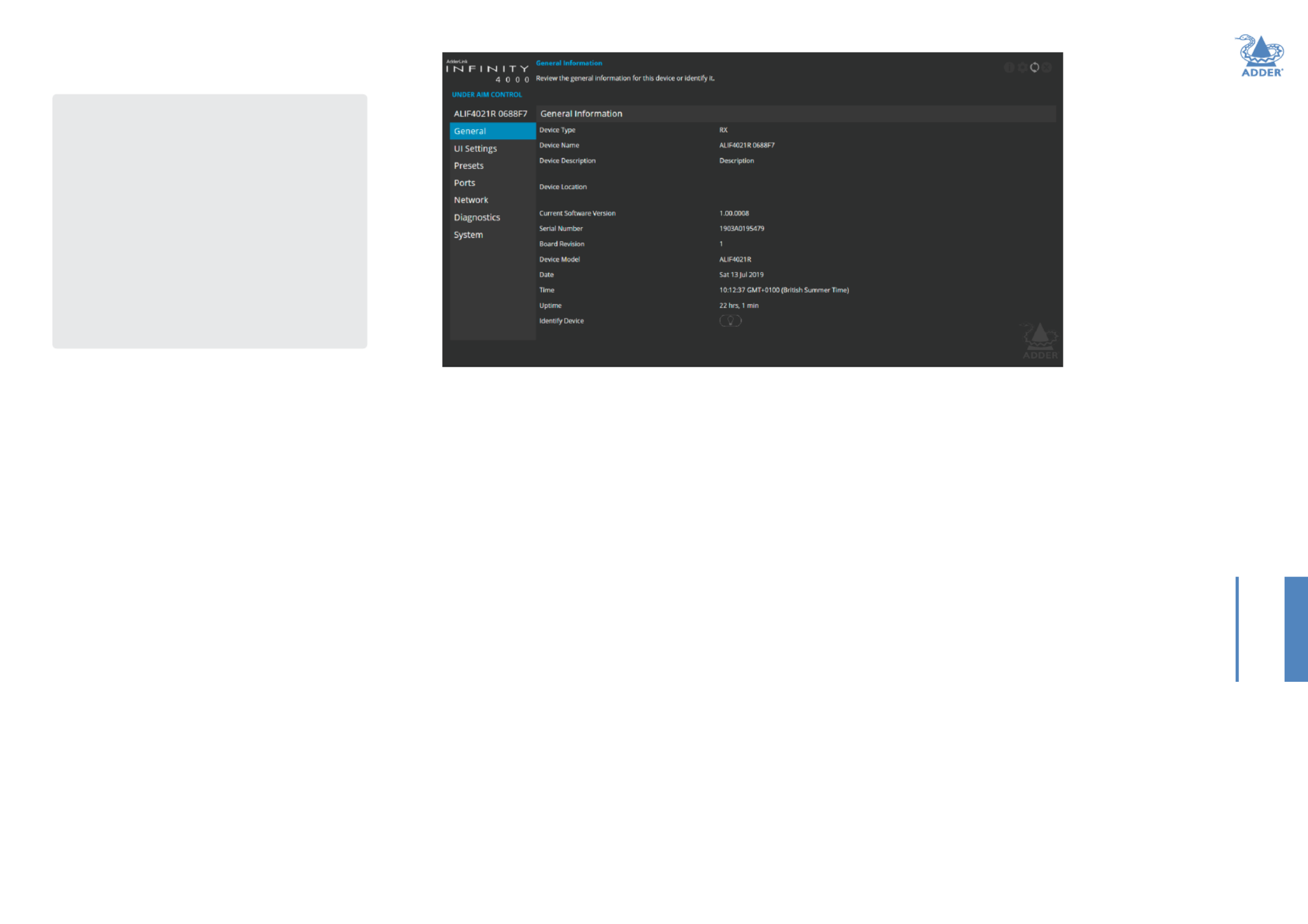
GeneralInformation
DeviceType - States whether the device is a transmitter (TX) or a
receiver (RX).
DeviceName - Name details that you can alter to distinguish this unit
from all others. The name entered here will be read by AIM servers (if
used) for administration purposes.
DeviceDescription - Allows you to optionally add a description of the
device. Useful when many ALIF units are being used.
DeviceLocation - Allows you to optionally add a description of the
device’s location. Useful when many ALIF units are being used.
CurrentSoftwareVersion - Displays the version number of the
currently installed internal software.
Serial Number - Displays the xed serial number of the device.
BoardRevision - Displays the revision number of the device’s main
circuit board.
DeviceModel - Displays the model number of the device.
Date and Time - Displays the current date and time used by the device.
Uptime - Shows the time period for which the device has currently
being running.
IdentifyDevice - When clicked, this button will cause the indicator on
the front panel of the device to ash to assist with identication when
multiple units are installed in the same area. A popup dialog will also be
displayed on screen showing all relevant identication details. Click the
Cancel button to stop the identication process or click the OK button
to close the popup (and then click the Identify Device button when
you’re ready to cancel this operation).
RX-GeneralInformation
To get here
You can access this page in two ways:
1 On the console keyboard attached to the RX unit, access
the OSD by pressing CTRL+ALT+C.
2 If necessary, click the GeneralInformation link.
OR
1 Connect a computer to the same network as the RX unit.
2 Run a web browser and enter the IP address of the RX
unit: (this is the default address when http://169.254.1.32
using SFP port 3). If you are using SFP port 4 then the
default address will be http://169.254.1.42
If the IP address is unknown, press the small button on the
front panel next to the OLED screen to reveal the value
for IP Address 3 (or IP Address 4) and use that address.
3 If necessary, click the GeneralInformation link.

27
INSTALLATIONCONFIGURATIONOPERATION
FURTHER
INFORMATION
INDEX
RX-UISettings
UISettings
OSDNoticationPosition(plusTimeout) - Determines the
location and persistence of notications issued on users’ screens.
OSD Banner Position (plus Timeout) - Determines the location and
persistence of banners displayed on users’ screens.
OSD Timeout - Determines the period of inactivity that should elapse
before the OSD menu is closed from user’s screens.
FrontPanelTimeout - Determines the period of inactivity that should
elapse before the front panel display should return to a blank state.
LED brightness - Determines the brightness of the front panel LED
indicator.
To get here
You can access this page in two ways:
1 On the console keyboard attached to the RX unit, access
the OSD by pressing CTRL+ALT+C.
2 Click the UISettings link.
OR
1 Connect a computer to the same network as the RX unit.
2 Run a web browser and enter the IP address of the RX
unit: (this is the default address when http://169.254.1.32
using SFP port 3). If you are using SFP port 4 then the
default address will be http://169.254.1.42
If the IP address is unknown, press the small button on the
front panel next to the OLED screen to reveal the value
for IP Address 3 (or IP Address 4) and use that address.
3 Click the UISettings link.

29
INSTALLATIONCONFIGURATIONOPERATION
FURTHER
INFORMATION
INDEX
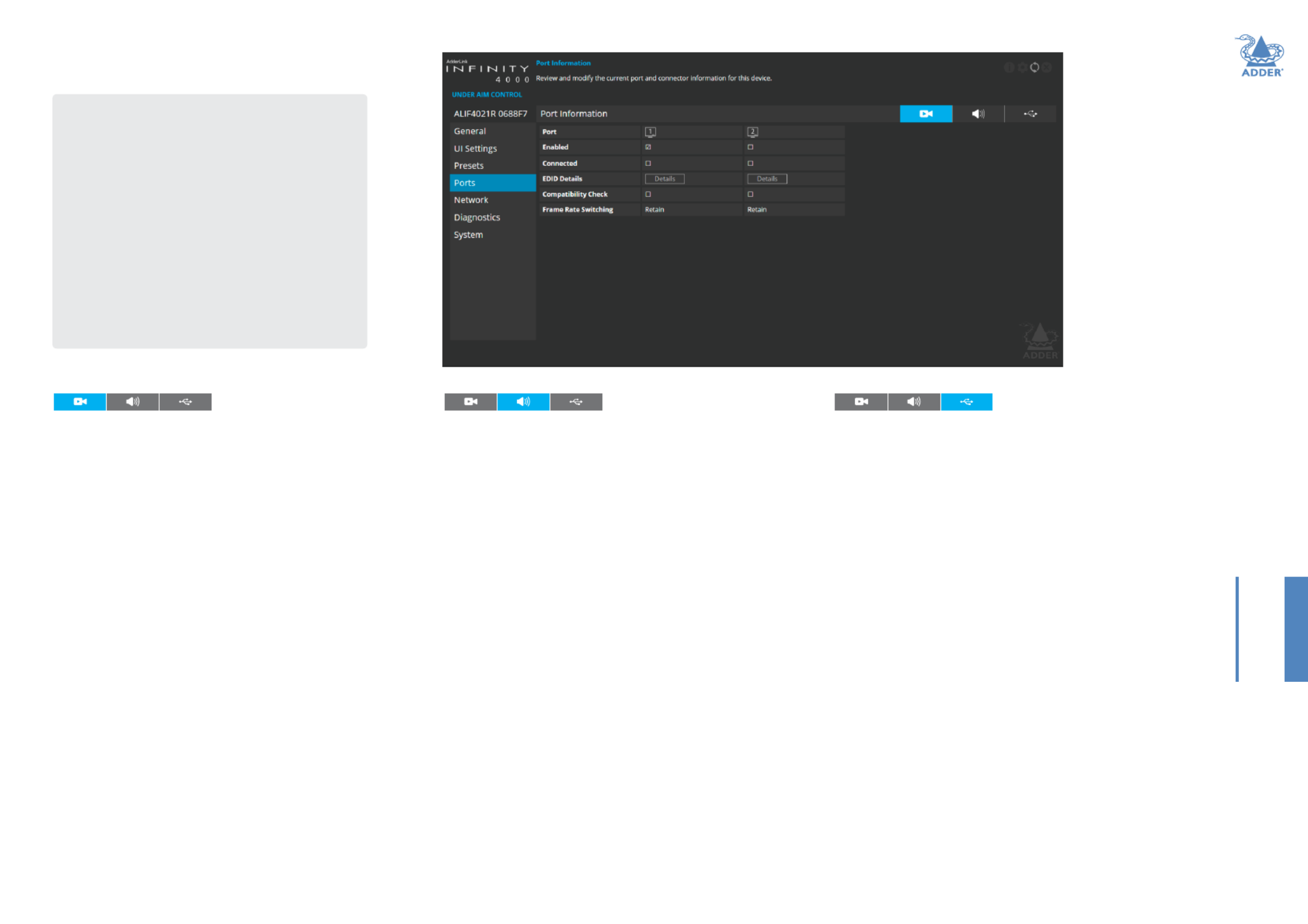
RX-Ports
VideoPorts
This page provides basic information about the two video ports located
on the RX unit.
Enabled - Conrms whether each video port is enabled or disabled.
Connected - Conrms whether functioning video displays are
connected to the two video ports.
EDIDDetails - Click the Details button to show a popup for the
connected video display. EDID details listed include: Manufacturer, model,
serial number, manufacture date, EDID version as well as supported (and
preferred) EDID modes.
Compatibility Check - Conrms whether video compatibility
between source and display device is checked. When ticked it prevents
displaying resolutions the monitor doesn’t support or, when unticked,
always sends resolutions to the monitor regardless of monitor’s declared
capabilities.
FrameRateSwitching - Determines the strategy to use for the frame
rate when switching resolutions. Similar in function to the Match Frame
Rate setting on AIM servers:
Force 60 - The frame rate is always forced to be 60Hz.
Retain - When switching to a different resolution with a potentially
different frame rate, it will retain the current frame.
Auto - The frame rate always changes to match the mode it is connected
to.
AudioPorts
This page provides basic information about the audio ports located on
the RX unit.
Enabled - Conrms whether the audio ports are enabled or disabled.
Connected - Conrms whether devices are connected to respective
ports.
Gain - Determines the microphone gain/amplication level:
None - no device connected on this port.
Mic - standard gain for normal microphone input devices.
Mic boost - 20dB boost to volume for microphone input devices.
USB Ports
This page provides basic information about the USB ports numbered 2
to 5 inclusive, located on the RX unit. USB port 1 is transparent and its
devices are not listed.
HIDOnly - When ticked, all ports are limited to supporting Human
Interface Devices only, such as keyboards and mice.
EnableIsochronousDevices - When ticked, a dedicated portion of
USB bandwidth is reserved for real time data transfers which must be
sent at a constant rate.
ConnectedDevices - This section lists all connected devices with
manufacturer and model details where reported. Click the Details button
against each device to view further information, such as the Device Type,
Protocol Version, Speed and Max Power Consumption.
To get here
You can access this page in two ways:
1 On the console keyboard attached to the RX unit, access
the OSD by pressing CTRL+ALT+C.
2 Click the Ports link.
OR
1 Connect a computer to the same network as the RX unit.
2 Run a web browser and enter the IP address of the RX
unit: (this is the default address when http://169.254.1.32
using SFP port 3). If you are using SFP port 4 then the
default address will be http://169.254.1.42
If the IP address is unknown, press the small button on the
front panel next to the OLED screen to reveal the value
for IP Address 3 (or IP Address 4) and use that address.
3 Click the Ports link.
Produkt Specifikationer
| Mærke: | Adder |
| Kategori: | Skifte |
| Model: | ALIF4021R |
Har du brug for hjælp?
Hvis du har brug for hjælp til Adder ALIF4021R stil et spørgsmål nedenfor, og andre brugere vil svare dig
Skifte Adder Manualer

26 December 2024
26 December 2024
23 December 2024
23 December 2024
23 December 2024
23 December 2024
23 December 2024
23 December 2024
23 December 2024
23 December 2024
Skifte Manualer
- Skifte QNAP
- Skifte Bosch
- Skifte SilverCrest
- Skifte CyberPower
- Skifte Panasonic
- Skifte Hager
- Skifte Extech
- Skifte TP-Link
- Skifte Ei Electronics
- Skifte Philips
- Skifte IFM
- Skifte Victron Energy
- Skifte Finder
- Skifte Behringer
- Skifte Emos
- Skifte HP
- Skifte Sennheiser
- Skifte Worx
- Skifte D-Link
- Skifte Asus
- Skifte Pyle
- Skifte One For All
- Skifte Yamaha
- Skifte Nedis
- Skifte Abus
- Skifte Planet
- Skifte Hama
- Skifte Belkin
- Skifte Edimax
- Skifte Theben
- Skifte Black Box
- Skifte Wago
- Skifte Clas Ohlson
- Skifte DataVideo
- Skifte TRENDnet
- Skifte Smartwares
- Skifte Trotec
- Skifte Honeywell
- Skifte Quigg
- Skifte Buffalo
- Skifte Linksys
- Skifte Cisco
- Skifte Huawei
- Skifte König
- Skifte Elro
- Skifte Steinel
- Skifte B-Tech
- Skifte Powerfix
- Skifte Alpine
- Skifte Netgear
- Skifte Totolink
- Skifte Eberle
- Skifte Grässlin
- Skifte Triax
- Skifte Tripp Lite
- Skifte Mercury
- Skifte Alcatel
- Skifte Goobay
- Skifte Digitus
- Skifte Alecto
- Skifte Flamingo
- Skifte Plantronics
- Skifte Ansmann
- Skifte Techly
- Skifte Tork
- Skifte Schneider
- Skifte Marmitek
- Skifte Basetech
- Skifte PreSonus
- Skifte Tesla
- Skifte GEV
- Skifte APC
- Skifte Kathrein
- Skifte GlobalTronics
- Skifte Elation
- Skifte Omnitronic
- Skifte Velleman
- Skifte LevelOne
- Skifte Perel
- Skifte Sonance
- Skifte Mercusys
- Skifte JUNG
- Skifte Vemer
- Skifte ORNO
- Skifte ZyXEL
- Skifte Tiptel
- Skifte Tenda
- Skifte Eaton
- Skifte Shimano
- Skifte Hikvision
- Skifte Monacor
- Skifte Paladin
- Skifte Brennenstuhl
- Skifte Ubiquiti Networks
- Skifte Cotech
- Skifte Aeon Labs
- Skifte Chamberlain
- Skifte GAO
- Skifte EnGenius
- Skifte AV:link
- Skifte Grandstream
- Skifte EVE
- Skifte Renkforce
- Skifte Manhattan
- Skifte SPC
- Skifte Dormakaba
- Skifte Mikrotik
- Skifte Electro Harmonix
- Skifte Aztech
- Skifte LogiLink
- Skifte DoorBird
- Skifte Eminent
- Skifte Kramer
- Skifte Vacmaster
- Skifte Brilliant
- Skifte Generac
- Skifte Kopp
- Skifte Provision-ISR
- Skifte Audiovox
- Skifte Fibaro
- Skifte Merlin Gerin
- Skifte Iogear
- Skifte ATen
- Skifte Vimar
- Skifte Smart-AVI
- Skifte Dahua Technology
- Skifte Chacon
- Skifte Vivolink
- Skifte Boss
- Skifte Nexa
- Skifte StarTech.com
- Skifte Doepke
- Skifte Rex
- Skifte Toolcraft
- Skifte Crestron
- Skifte Lindy
- Skifte Russound
- Skifte Emerson
- Skifte Elektrobock
- Skifte Lancom
- Skifte Kemo
- Skifte Delta Dore
- Skifte Audac
- Skifte CYP
- Skifte AMX
- Skifte Homematic IP
- Skifte H-Tronic
- Skifte Intellinet
- Skifte Whale
- Skifte Legrand
- Skifte Shelly
- Skifte SunBriteTV
- Skifte Steren
- Skifte Heitronic
- Skifte Intelix
- Skifte Kaiser
- Skifte Equip
- Skifte Alfatron
- Skifte PCE
- Skifte Ernitec
- Skifte Speaka
- Skifte Setti+
- Skifte BZBGear
- Skifte KanexPro
- Skifte Gefen
- Skifte RGBlink
- Skifte Profile
- Skifte Blustream
- Skifte Intermatic
- Skifte KlikaanKlikuit
- Skifte Sylvania
- Skifte Matrox
- Skifte Merten
- Skifte Sygonix
- Skifte UPM
- Skifte Gira
- Skifte PAC
- Skifte Wentronic
- Skifte Monoprice
- Skifte IPGARD
- Skifte OSD Audio
- Skifte Unify
- Skifte Berker
- Skifte Suevia
- Skifte SIIG
- Skifte Advantech
- Skifte Micro Connect
- Skifte Extron
- Skifte Avocent
- Skifte PureLink
- Skifte Comet
- Skifte Ebode
- Skifte Robbe
- Skifte ICasa
- Skifte INOGENI
- Skifte Cambium Networks
- Skifte Kraus & Naimer
- Skifte Noble
- Skifte Intertechno
- Skifte Extreme Networks
- Skifte Ecler
- Skifte Inverto
- Skifte Rule
- Skifte Phoenix Contact
- Skifte Seuthe
- Skifte Maclean Energy
- Skifte SmartAVI
- Skifte Cudy
- Skifte Mach Power
- Skifte SEC24
- Skifte Cooking Performance Group
- Skifte STI
- Skifte Atlona
- Skifte Adviti
- Skifte Flic
- Skifte HELGI
- Skifte IB Connect
- Skifte Liberty
- Skifte Hamlet
- Skifte Noark
- Skifte 2USB
- Skifte Roline
- Skifte KVM-TEC
- Skifte Epiphan
- Skifte Ebara
- Skifte Axing
- Skifte Juniper
- Skifte Raritan
- Skifte ConnectPro
- Skifte Atlantis Land
- Skifte Pizzato Elettrica
- Skifte Baco
- Skifte SEADA
- Skifte CSL
- Skifte Luxul
Nyeste Skifte Manualer

29 Marts 2025
27 Februar 2025

21 Februar 2025
30 Januar 2025
30 Januar 2025
30 Januar 2025
30 Januar 2025
29 Januar 2025
14 Januar 2025
14 Januar 2025