Asus M2N-X Manual
Læs nedenfor 📖 manual på dansk for Asus M2N-X (92 sider) i kategorien Bundkort. Denne guide var nyttig for 27 personer og blev bedømt med 4.5 stjerner i gennemsnit af 2 brugere
Side 1/92

Motherboard
M2N-X

ii
Copyright © 2007 ASUSTeK COMPUTER INC. All Rights Reserved.
No part of this manual, including the products and software described in it, may be reproduced,
transmitted, transcribed, stored in a retrieval system, or translated into any language in any form
or by any means, except documentation kept by the purchaser for backup purposes, without the
express written permission of ASUSTeK COMPUTER INC. (“ASUS”).
Product warranty or service will not be extended if: (1) the product is repaired, modied or
altered, unless such repair, modication of alteration is authorized in writing by ASUS; or (2) the
serial number of the product is defaced or missing.
ASUS PROVIDES THIS MANUAL “AS IS” WITHOUT WARRANTY OF ANY KIND, EITHER EXPRESS
OR IMPLIED, INCLUDING BUT NOT LIMITED TO THE IMPLIED WARRANTIES OR CONDITIONS OF
MERCHANTABILITY OR FITNESS FOR A PARTICULAR PURPOSE. IN NO EVENT SHALL ASUS,
ITS DIRECTORS, OFFICERS, EMPLOYEES OR AGENTS BE LIABLE FOR ANY INDIRECT, SPECIAL,
INCIDENTAL, OR CONSEQUENTIAL DAMAGES (INCLUDING DAMAGES FOR LOSS OF PROFITS, LOSS
OF BUSINESS, LOSS OF USE OR DATA, INTERRUPTION OF BUSINESS AND THE LIKE), EVEN IF ASUS
HAS BEEN ADVISED OF THE POSSIBILITY OF SUCH DAMAGES ARISING FROM ANY DEFECT OR
ERROR IN THIS MANUAL OR PRODUCT.
SPECIFICATIONS AND INFORMATION CONTAINED IN THIS MANUAL ARE FURNISHED FOR
INFORMATIONAL USE ONLY, AND ARE SUBJECT TO CHANGE AT ANY TIME WITHOUT NOTICE, AND
SHOULD NOT BE CONSTRUED AS A COMMITMENT BY ASUS. ASUS ASSUMES NO RESPONSIBILITY
OR LIABILITY FOR ANY ERRORS OR INACCURACIES THAT MAY APPEAR IN THIS MANUAL,
INCLUDING THE PRODUCTS AND SOFTWARE DESCRIBED IN IT.
Products and corporate names appearing in this manual may or may not be registered
trademarks or copyrights of their respective companies, and are used only for identication or
explanation and to the owners’ benet, without intent to infringe.
E3147
Second Edition V2.0
March 2007

iii
Contents
Notices ................................................................................................ vi
Safety information ..............................................................................vii
M2N-X specications summary ............................................................ x
Chapter 1: Product introduction
1.1 Welcome! .............................................................................. 1-2
1.2 Package contents ................................................................. 1-2
1.3 Special features .................................................................... 1-2
1.3.1 Product highlights ................................................... 1-2
1.3.2 Innovative ASUS features ...................................... 1-4
1.4 Before you proceed .............................................................. 1-5
1.5 Motherboard overview .......................................................... 1-6
1.5.1 Motherboard layout ................................................ 1-6
1.5.2 Placement direction ................................................ 1-7
1.5.3 Screw holes ............................................................. 1-7
1.6 Central Processing Unit (CPU) .............................................. 1-8
1.6.1 Installing the CPU .................................................... 1-8
1.6.2 Installing the heatsink and fan .............................. 1-10
1.7 System memory .................................................................. 1-12
1.7.1 Overview ............................................................... 1-12
1.7.2 Memory congurations ......................................... 1-12
1.7.3 Installing a DIMM ................................................... 1-15
1.7.4 Removing a DIMM .................................................. 1-15
1.8 Expansion slots ................................................................... 1-16
1.8.1 Installing an expansion card .................................. 1-16
1.8.2 Conguring an expansion card .............................. 1-16
1.8.3 PCI slots ................................................................ 1-18
1.8.4 PCI Express p3-x1 slot ...............................................1-18
1.8.5 PCI Express x16 slot ............................................. 1-18
1.9 Jumpers .............................................................................. 1-19
1.10 Connectors ......................................................................... 1-21
1.10.1 Rear panel connectors .......................................... 1-21
1.10.2 Internal connectors ............................................... 1-22

iv
Contents
Chapter 2: BIOS setup
2.1 Managing and updating your BIOS ........................................ 2-2
2.1.1 Creating a bootable oppy disk .............................. 2-2
2.1.2 ASUS EZ Flash utility ............................................... 2-3
2.1.3 AFUDOS utility ........................................................ 2-4
2.1.4 ASUS CrashFree BIOS 2 utility ................................ 2-6
2.1.5 ASUS Update utility ................................................ 2-8
2.2 BIOS setup program ............................................................ 2-11
2.2.1 BIOS menu screen ................................................. 2-12
2.2.2 Menu bar ............................................................... 2-12
2.2.3 Navigation keys ..................................................... 2-12
2.2.4 Menu items ........................................................... 2-13
2.2.5 Sub-menu items .................................................... 2-13
2.2.6 Conguration elds ............................................... 2-13
2.2.7 Pop-up window ...................................................... 2-13
2.2.8 Scroll bar ............................................................... 2-13
2.2.9 General help .......................................................... 2-13
2.3 Main menu ........................................................................... 2-14
2.3.1 System Time ......................................................... 2-14
2.3.2 System Date ......................................................... 2-14
2.3.3 Legacy Diskette A ............................................... 2-14
2.3.4 IDE Conguration .................................................. 2-15
2.3.5 Primary IDE Master/Slave ...................................... 2-15
2.3.6 SATA1, SATA2, SATA3, and SATA4 .................... 2-17
2.3.7 System Information............................................... 2-18
2.4 Advanced menu .................................................................. 2-19
2.4.1 Jumperfree Conguration ..................................... 2-19
2.4.2 CPU Conguration ................................................ 2-21
2.4.3 Chipset .................................................................. 2-22
2.4.4 Onboard Devices Conguration ............................. 2-28
2.4.5 PCI PnP .................................................................. 2-29
2.4.6 USB Conguration ................................................. 2-30
2.5 Power menu ........................................................................ 2-31
2.5.1 Suspend Mode ....................................................... 2-31
2.5.2 ACPI Version Features .......................................... 2-31

v
Contents
Chapter 3: Software support
3.1 Installing an operating system .............................................. 3-2
3.2 Support CD information ........................................................ 3-2
3.2.1 Running the support CD .......................................... 3-2
3.2.2 Drivers menu ........................................................... 3-3
3.2.3 Utilities menu .......................................................... 3-4
3.2.4 Make Disk menu ...................................................... 3-5
3.2.5 Manual menu ........................................................... 3-6
3.2.6 ASUS Contact information ...................................... 3-7
3.2.7 Other information ................................................... 3-7
3.3 Creating a RAID driver disk ................................................... 3-9
2.5.3 ACPI APIC Support ................................................ 2-31
2.5.4 APM Conguration ................................................ 2-32
2.5.5 Hardware Monitor .................................................. 2-33
2.6 Boot menu .......................................................................... 2-34
2.6.1 Boot Device Priority .............................................. 2-34
2.6.2 Boot Settings Conguration ................................. 2-35
2.6.3 Security ................................................................. 2-36
2.7 Exit menu ............................................................................ 2-38

vi
Notices
Federal Communications Commission Statement
This device complies with Part 15 of the FCC Rules. Operation is subject to
the following two conditions:
•
This device may not cause harmful interference, and
•
This device must accept any interference received including
interference that may cause undesired operation.
This equipment has been tested and found to comply with the limits for a
Class B digital device, pursuant to Part 15 of the FCC Rules. These limits
are designed to provide reasonable protection against harmful interference
in a residential installation. This equipment generates, uses and can radiate
radio frequency energy and, if not installed and used in accordance with
manufacturer’s instructions, may cause harmful interference to radio
communications. However, there is no guarantee that interference will
not occur in a particular installation. If this equipment does cause harmful
interference to radio or television reception, which can be determined by
turning the equipment off and on, the user is encouraged to try to correct
the interference by one or more of the following measures:
•
Reorient or relocate the receiving antenna.
•
Increase the separation between the equipment and receiver.
•
Connect the equipment to an outlet on a circuit different from that to
which the receiver is connected.
•
Consult the dealer or an experienced radio/TV technician for help.
Canadian Department of Communications Statement
This digital apparatus does not exceed the Class B limits for radio noise
emissions from digital apparatus set out in the Radio Interference
Regulations of the Canadian Department of Communications.
This class B digital apparatus complies with Canadian
ICES-003.
The use of shielded cables for connection of the monitor to the graphics
card is required to assure compliance with FCC regulations. Changes
or modications to this unit not expressly approved by the party
responsible for compliance could void the user’s authority to operate
this equipment.

vii
Safety information
Electrical safety
•
To prevent electrical shock hazard, disconnect the power cable from
the electrical outlet before relocating the system.
•
When adding or removing devices to or from the system, ensure that
the power cables for the devices are unplugged before the signal cables
are connected. If possible, disconnect all power cables from the existing
system before you add a device.
•
Before connecting or removing signal cables from the motherboard,
ensure that all power cables are unplugged.
•
Seek professional assistance before using an adapter or extension cord.
These devices could interrupt the grounding circuit.
•
Make sure that your power supply is set to the correct voltage in your
area. If you are not sure about the voltage of the electrical outlet you
are using, contact your local power company.
•
If the power supply is broken, do not try to x it by yourself. Contact a
qualied service technician or your retailer.
Operation safety
•
Before installing the motherboard and adding devices on it, carefully
read all the manuals that came with the package.
•
Before using the product, make sure all cables are correctly connected
and the power cables are not damaged. If you detect any damage,
contact your dealer immediately.
•
To avoid short circuits, keep paper clips, screws, and staples away from
connectors, slots, sockets and circuitry.
•
Avoid dust, humidity, and temperature extremes. Do not place the
product in any area where it may become wet.
•
Place the product on a stable surface.
•
If you encounter technical problems with the product, contact a
qualied service technician or your retailer.
The symbol of the crossed out wheeled bin indicates that the product
(electrical and electronic equipment) should not be placed in municipal
waste. Please check local regulations for disposal of electronic products.

viii
About this guide
This user guide contains the information you need when installing and
conguring the motherboard.
How this guide is organized
This guide contains the following parts:
• Chapter 1: Product introduction
This chapter describes the features of the motherboard and the new
technology it supports.
• Chapter 2: BIOS setup
This chapter tells how to change system settings through the BIOS
Setup menus. Detailed descriptions of the BIOS parameters are also
provided.
• Chapter 3: Software support
This chapter describes the contents of the support CD that comes with
the motherboard package.
Where to nd more information
Refer to the following sources for additional information and for product
and software updates.
1. ASUS websites
The ASUS website provides updated information on ASUS hardware and
software products. Refer to the ASUS contact information.
2. Optional documentation
Your product package may include optional documentation, such as
warranty yers, that may have been added by your dealer. These
documents are not part of the standard package.

ix
Conventions used in this guide
To make sure that you perform certain tasks properly, take note of the
following symbols used throughout this manual.
Typography
Bold text Indicates a menu or an item to select.
Italics
Used to emphasize a word or a phrase.
<Key> Keys enclosed in the less-than and greater-than
sign means that you must press the enclosed
key.
Example: <Enter> means that you must press
the Enter or Return key.
<Key1>+<Key2>+<Key3> If you must press two or more keys
simultaneously, the key names are linked with a
plus sign (+).
Example: <Ctrl>+<Alt>+<D>
Command Means that you must type the command
exactly as shown, then supply the required item
or value enclosed in brackets.
Example: At the DOS prompt, type the
command line:
awdash M2N-X.BIN
DANGER/WARNING: Information to prevent injury to yourself
when trying to complete a task.
CAUTION: Information to prevent damage to the components
when trying to complete a task.
NOTE: Tips and additional information to help you complete a
task.
IMPORTANT: Instructions that you MUST follow to complete a
task.

x
M2N-X specications summary
(continued on the next page)
CPU
Chipset
Front Side Bus
Memory
Expansion slots
Storage
High Denition Audio
LAN
USB
Overclocking features
Special features
Supports AMD socket AM2 for AMD Athlon™ 64 FX/
Athlon™ 64 X2/Athlon™ 64/Sempron processors
AMD64 architecture enables simultaneous 32-bit and
64-bit computing
Supports AMD Cool ‘n’ Quiet™ Technology
AMD Live!™ Ready
NVIDIA® nForce® 520 MCP (MCP65S)
2000/1600 MT/s
Dual-channel memory architecture
2 x 240-pin DIMM sockets support up to 2 GB of
unbuffered/ECC/non-ECC 800/667/533 MHz
1 x PCI Express™ x16 slot
2 x PCI Express™ p10-x1 slots
3 x PCI slots
Supports:
- 1 x Ultra DMA 133/100/66/33 interfaces
- 4 x Serial ATA 3 Gb/s devices
- NVIDIA® MediaShield™ RAID supports RAID 0, RAID
1, RAID 0+1, RAID 5, and JBOD span cross Serial
ATA drives
ALC883-GR 6-channel High Denition Audio Azalia CODEC
1 x Coaxial S/PDIF out port
Supports Enumeration Technology
Supports Multi-Streaming Technology
10/100 PHY
Supports up to 10 USB 2.0/1.1 ports (six on board and
four on back)
Stepless Frequency Selection (SFS):
- HT LINK frequency tuning from 200MHz up to 300
MHz at 1MHz increment;
Prole
Overclocking Protection:
- ASUS C.P.R. (CPU Parameter Recall)
ASUS EZ DIY:
- ASUS CrashFree BIOS 2
- ASUS EZ Flash
ASUS Install
ASUS MyLogo™
ASUS Dram Burnt Proof
ASUS Fanless Thermal Solution (heatsink)

xi
M2N-X specications summary
Manageability
BIOS features
Rear panel
Internal Connector
Manageability
Form Factor
Support CD contents
4 Mb Flash ROM, AMI BIOS, PnP, DMI, Wfm2.0, ACPI2.0a,
SM BIOS2.3, CPU Multiplier
1 x Parallel port
1 x LAN (RJ-45) port
4 x USB 2.0/1.1 ports
1 x Coaxial S/PDIF Out port
1 x COM port
1 x PS/2 keyboard port
1 x PS/2 mouse port
6-channel audio ports
1 x 10-pin Azalia Analog Front panel Audio connector
1 x CD audio in connector
1 x CPU fan connector
1 x Chassis fan connector
1 x Floppy disk drive connector
1 x speaker connector
1 x IDE connector for two devices
4 x Serial ATA connectors
3 x USB 2.0 connectors for 6 additional USB 2.0 ports
1 x 24-pin ATX power connector
1 x 4-pin ATX 12V power connector
1 x System panel connector
WOR by Ring, WOL by PME, WOR by PME, Chassis
Intrusion(option), PXE
ATX Form Factor: 12 in. x 7.6 in. (30.5cm x 19.3cm)
Device drivers
ASUS PC Probe II
ASUS Update
NVIDIA® MediaShield™ RAID
Anti-virus software (OEM version)
*Specications are subject to change without notice.

xii

1
Product
introduction
This chapter describes the motherboard
features and the new technologies
it supports.

1-2 Chapter 1: Product introduction
1.1 Welcome!
T h a n k y o u f o r b u y i n g a n A S U S ® M 2 N - X m o t h e r b o a r d !
The motherboard delivers a host of new features and latest technologies,
making it another standout in the long line of ASUS quality motherboards!
Before you start installing the motherboard, and hardware devices on it,
check the items in your package with the list below.
If any of the above items is damaged or missing, contact your retailer.
1.2 Package contents
Check your motherboard package for the following items.
Motherboard ASUS M2N-X motherboard
Cables 1 x Serial ATA cable
1 x Serial ATA power cable
1 x Ultra DMA 133/100/66 cable
1 x Floppy disk drive cable
Accessories I/O shield
Application CD ASUS motherboard support CD
Documentation User guide
1.3 Special features
1.3.1 Product highlights
Latest processor technology
The motherboard supports AMD socket AM2 single-core Athlon 64/
Sempron and dual-core Athlon 64 X2/Athlon 64 FX processors with 2MB/
1MB/512KB L2 cache, which is based on 64-bit architecture. It features
2000/1600 MT/s HyperTransport Bus, dual-channel ECC, non-ECC and un-
buffered DDR2 800 memory support and AMD Cool ‘n’ Quiet Technology.
See page 1-8 for details.

ASUS M2N-X 1-3
NVIDIA® nForc e™ 520 M CP c hipsets
The NVIDIA® nForce™ 520 media and communications processor (MCP)
builds on the award-winning single-chip, scalable architecture of the NVIDIA
nForce MCP.
DD R2 memory support
The motherboard supports DDR2 memory which features data transfer
rates of 800MHz/667 MHz/533 MHz to meet the higher bandwidth
requirements of the latest 3D graphics, multimedia, and Internet
applications. The dual-channel DDR2 architecture doubles the bandwidth
of your system memory to boost system performance, eliminating
bottlenecks with peak bandwidths of up to 12.8 GB/s. See pages 1-12 to
1-14 for details.
PCI Express™ interface
The motherboard fully supports PCI Express, the latest I/O interconnect
technology that speeds up the PCI bus. PCI Express features point-to-point
serial interconnections between devices and allows higher clockspeeds by
carrying data in packets. This high speed interface is software compatible
with existing PCI specications. See page 1-18 for details.
AM D Cool ‘ n’ Q uiet Technology
The motherboard supports the AMD Cool ‘n’ Quiet Technology, which
monitors system operation and automatically adjusts CPU voltage and
frequency for a cool and quiet operating environment.
Serial ATA 3Gb/s technology
The motherboard supports next-generation SATA hard drives based on
the new SATA 3Gb/s storage specication. The onboard NVIDIA® nForce
520 MCP southbridge allows RAID 0, RAID 1, RAID 0+1, RAID 5, and JBOD
congurations for four SATA connectors.
10/100 Mbps LAN
Easy connectivity to your network or broadband connection with the
onboard LAN port. Allows you to play online games without buying
expensive additional LAN cards. See page 1-21 for details.
USB 2.0 te ch nology
The motherboard implements the Universal Serial Bus (USB) 2.0
specication, dramatically increasing the connection speed from the
12 Mbps bandwidth on USB 1.1 to a fast 480 Mbps on USB 2.0. USB 2.0 is
backward compatible with USB 1.1. See page 1-26 for details.
ASUS M2N-X 1-5
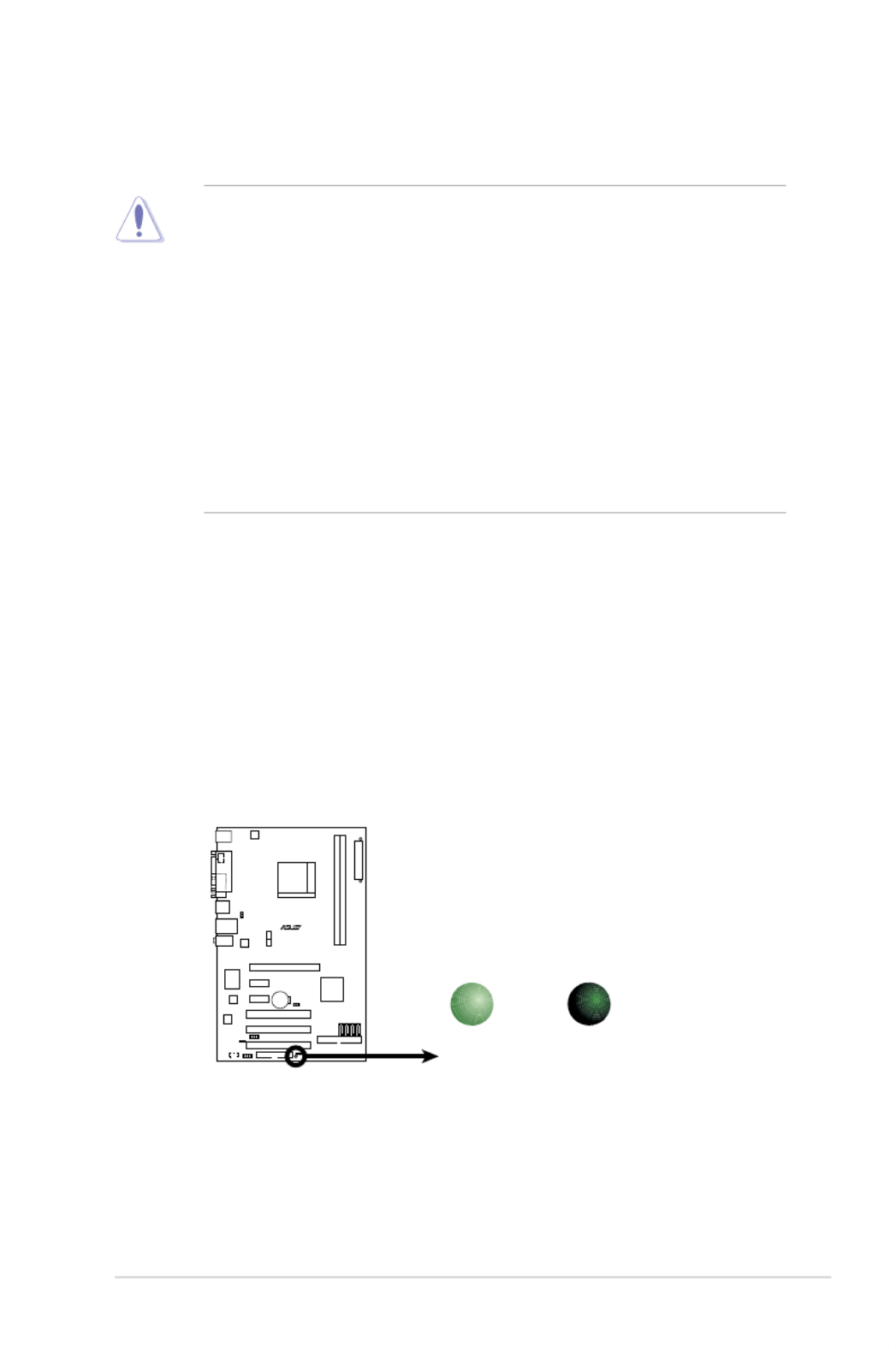
Onboard LED
The motherboard comes with a standby power LED that lights up to
indicate that the system is ON, in sleep mode, or in soft-off mode.
This is a reminder that you should shut down the system and unplug
the power cable before removing or plugging in any motherboard
component. The illustration below shows the location of the onboard
LED.
1.4 Before you proceed
Take note of the following precautions before you install motherboard
components or change any motherboard settings.
• Unplug the power cord from the wall socket before touching any
component.
• Use a grounded wrist strap or touch a safely grounded object or
a metal object, such as the power supply case, before handling
components to avoid damaging them due to static electricity
• Hold components by the edges to avoid touching the ICs on them.
• Whenever you uninstall any component, place it on a grounded
antistatic pad or in the bag that came with the component.
• Before you install or remove any component, ensure that the ATX
power supply is switched off or the power cord is detached from
the power supply. Failure to do so may cause severe damage to the
motherboard, peripherals, and/or components.
M2N-X
M2N-X Onboard LED
SB_PWR
ON
Standby
Power
OFF
Powere
d
Off

1-6 Chapter 1: Product introduction
1.5.1 Motherboard layout
1.5 Motherboard overview
19.3cm(7.6in)
30.5cm(12.0in)
M2N-X
DDR2 DIMM_A1 (64 bit,240-pin module)
DDR2 DIMM_B1 (64 bit,240-pin module)
EATXPWR
PWR_FAN CPU_FAN
Socket AM2
ATX12V
AUDIO
LAN_USB12
USB34
SPDIF_O1
PARALLE PORT
COM1
PS/2KBMS
T: Mouse
B: Keyboard
PCI2
PCI1
PCI3
PCIEX16
PCIEX1_1
PCIEX1_2
Nvidia
MCP65S
SATA4
SATA3
SATA2
SATA1
FLOPPY
PRI_IDE
SPEAKER
F_PANELAAFP USB78USB910
USB56
CLRTC
USBPW7-10
USBPW56
SB_PWR
R
CD
CR2032 3V
Lithium Cell
CMOS Power
4Mb
BIOS
ALC883
PS2_USBPW1-4
Super I/O
10/100
PHY

ASUS M2N-X 1-7
M2N-X
R
Do not overtighten the screws! Doing so can damage the motherboard.
1.5.2 Placement direction
When installing the motherboard, make sure that you place it into the
chassis in the correct orientation. The edge with external ports goes to the
rear part of the chassis as indicated in the image below.
Place this si de towards
the rear of the chassis
1.5.3 Screw holes
Place six (6) screws into the holes indicated by circles to secure the
motherboard to the chassis.
1-8 Chapter 1: Product introduction
1.6 Central Processing Unit (CPU)
The motherboard comes with a 940-pin AM2 socket designed for the AMD
Athlon™ 64 X2/Athlon™ 64/Athlon™ FX/Sempron™ processor.
The AM2 socket has a different pinout from the 940-pin socket designed
for the AMD Opteron™ processor. Make sure you use a CPU is designed
for the AM2 socket. The CPU ts in only one correct orientation. DO NOT
force the CPU into the socket to prevent bending the connectors on the
socket and damaging the CPU!
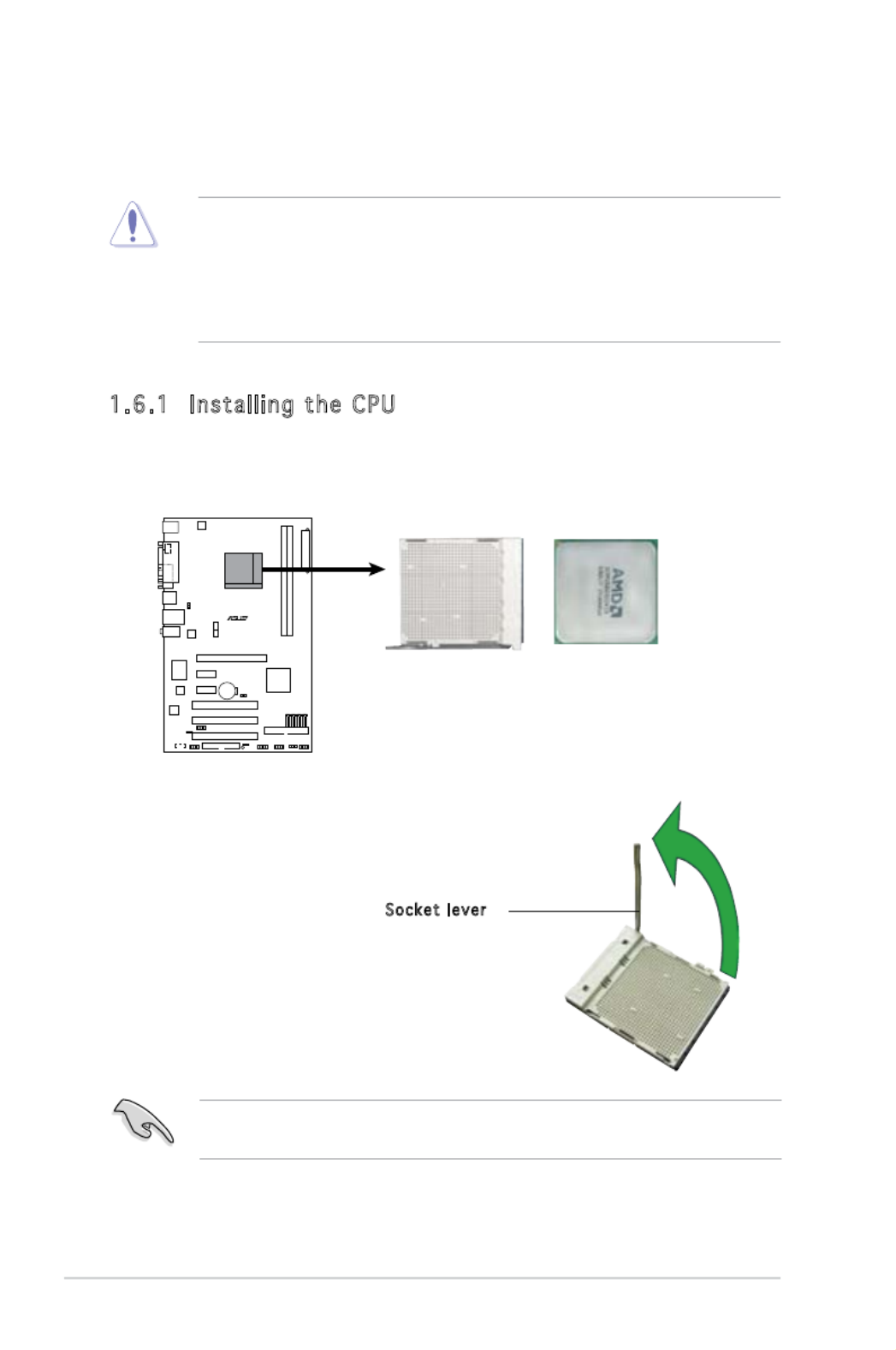
1.6.1 Installing the CPU
To install a CPU.
1. Locate the CPU socket on the motherboard.
2. Unlock the socket by pressing the
lever sideways, then lift it up to a
90°-100° angle.
Make sure that the socket lever is lifted up to 90°-100° angle, otherwise
the CPU does not t in completely.
Socket lever
M2N-X
M2N-X CPU Socket AM2

ASUS M2N-X 1-9
3. Position the CPU above the
socket such that the CPU corner
with the gold triangle matches
the socket corner with a small
triangle.
4. Carefully insert the CPU into the
socket until it ts in place.
The CPU ts only in one correct orientation. DO NOT force the CPU into
the socket to prevent bending the pins and damaging the CPU!
5. When the CPU is in place, push
down the socket lever to secure
the CPU. The lever clicks on the
side tab to indicate that it is
locked.
6. Install a CPU heatsink and fan
following the instructions that
came with the heatsink package.
Gold triangle
Sm all tri a ng l e
7. Connect the CPU fan cable to the CPU_FAN connector on the
motherboard.
Do not forget to connect the CPU fan connector! Hardware monitoring
errors can occur if you fail to plug this connector.
M2N-X
M2N-X
CPU Fan Connector
CPU_FAN
GND
CPU FAN PWR
CPU FAN IN
CPU FAN PWM

1-10 Chapter 1: Product introduction
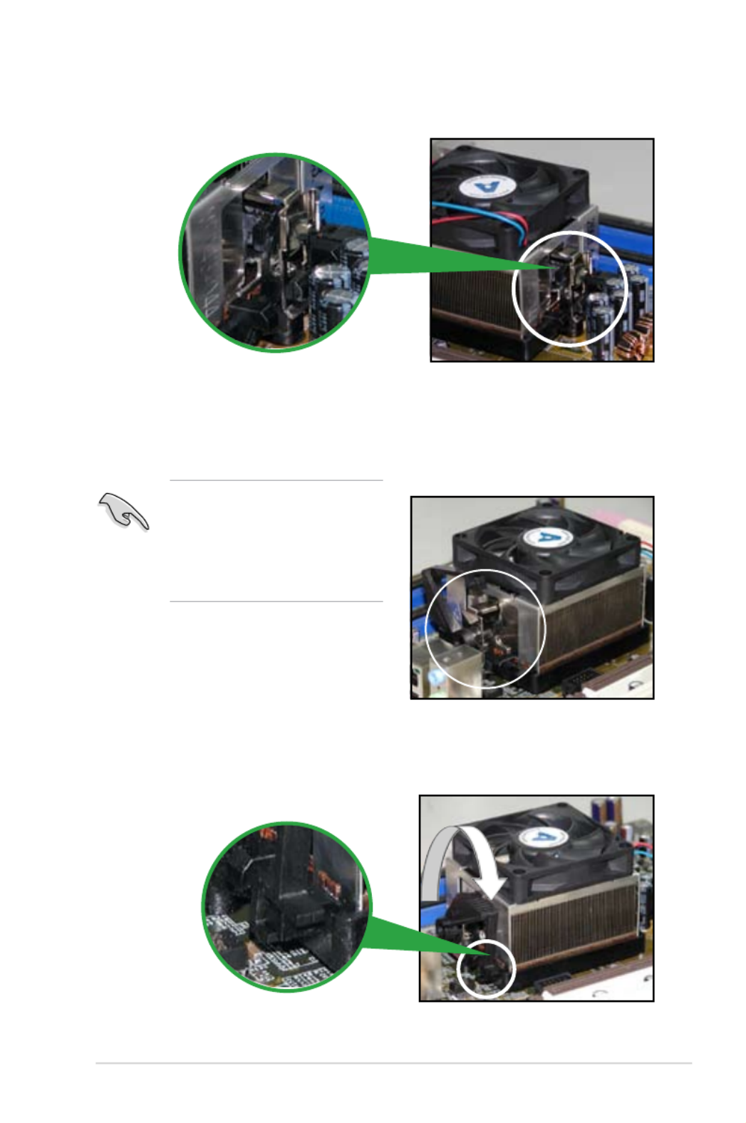
1.6.2 Installing the heatsink and fan
The AMD Athlon™ 64 X2/Athlon™ 64/Athlon™ FX/Sempron™ processor
require a specially designed heatsink and fan assembly to ensure optimum
thermal condition and performance.
Follow these steps to install the CPU heatsink and fan.
1. Place the heatsink on top of the installed CPU, making sure that the
heatsink ts properly on the retention module base.
Re tention Module Base
CPU Heatsink
CPU F an
Re tention b racke t lockRe tention b racke t
Make sure that you use only qualied heatsink and fan assembly.
• The retention module base is already installed on the motherboard
upon purchase.
• You do not have to remove the retention module base when
installing the CPU or installing other motherboard components.
• If you purchased a separate CPU heatsink and fan assembly, make
sure that a Thermal Interface Material is properly applied to the CPU
heatsink or CPU before you install the heatsink and fan assembly.
Your boxed CPU heatsink and fan assembly should come with installation
instructions for the CPU, heatsink, and the retention mechanism. If the
instructions in this section do not match the CPU documentation, follow
the latter.
ASUS M2N-X 1-11
2. Attach one end of the retention bracket to the retention module base.
3. Align the other end of the retention bracket (near the retention
bracket lock) to the retention module base. A clicking sound denotes
that the retention bracket is in place.
4. Push down the retention bracket lock on the retention mechanism to
secure the heatsink and fan to the module base.
Make sure that the fan and
heatsink assembly perfectly
ts the retention mechanism
module base; otherwise, you
cannot snap the retention
bracket in place.

1-12 Chapter 1: Product introduction
• You may install varying memory sizes in Channel A and Channel B.
The system maps the total size of the lower-sized channel for the
dual-channel conguration. Any excess memory from the higher-
sized channel is then mapped for single-channel operation.
• Always install DIMMs with the same CAS latency. For optimum
compatibility, it is recommended that you obtain memory modules
from the same vendor.
• This motherboard does not support memory modules made up of
128 Mb chips or double sided x16 memory modules.
1.7.2 Memory configurations
You may install 256 MB, 512 MB, and 1 GB unbuffered/ECC/non-ECC DDR2
DIMMs into the DIMM sockets.
1.7 System memory
1.7.1 Overview
The motherboard comes with four Double Data Rate 2 (DDR2) Dual Inline
Memory Modules (DIMM) sockets.
A DDR2 module has the same physical dimensions as a DDR DIMM but has
a 240-pin footprint compared to the 184-pin DDR DIMM. DDR2 DIMMs are
notched differently to prevent installation on a DDR DIMM socket.
The gure illustrates the location of the DDR2 DIMM sockets:
Channel Sockets
Channel A DIMM_A1
Channel B DIMM_B1
M2N-X
M2N-X
240-pin DDR2 DIMM Sockets
128 Pins112 Pins
DIMM_B1
DIMM_A1

ASUS M2N-X 1-13
Qualified Vendors Lists (QVL)
512MB Kingston KVR800D2N5/512 Samsung SS K4T51083QC-ZCE7 • • •
512MB Kingston KVR800D2N5/512 Promos SS V59C1512804QBF25S0054707PEBPA • • •
1G Kingston KVR800D2N5/1G Samsung DS K4T51083QC-ZCE7 • • •
1G Kingston KHX6400D2LL/1G Kingston DS Heat-Sink Package • • •
1G Kingston KVR800D2N5/1G Nanya DS NT5TU64M8BE-25C62321800CP • • •
512MB Samsung KR M378T6553CZ3-CE7 Samsung SS K4T51083QC-ZCE7 • • •
1G Samsung KR M378T2953CZ3-CE7 Samsung DS K4T51083QC-ZCE7 • • •
512MB Samsung KR M391T6553CZ3-CE7 Samsung SS K4T51083QC-ZCE7(ECC) • • •
1G Samsung KR M391T2953CZ3-CE7 Samsung DS K4T51083QC-ZCE7(ECC) • • •
256MB Qimonda HYS64T32001HU-2.5-A Qimonda SS HYB18T256800AF25SSS49313 • • •
512MB Qimonda HYS64T64020HU-2.5-A Qimonda DS HYB18T256800AF25SSS25063 • • •
512MB Micron MT9HTF6472AY-80ED4 Micron SS 6ED22D9GKX(ECC) • • •
512MB Corsair CM2X512A-6400 Corsair SS Heat-Sink Package • • •
1G Corsair CM2X1024-6400 Corsair DS Heat-Sink Package • • •
512MB HY HYMP564U64AP8-S6 AA Hynix SS HY5PS12821AFP-S6 • • •
512MB HY HYMP564U64BP8-S5 AB Hynix SS HY5PS12821BFP-S5 • • •
1G HY HYMP512U64AP8-S6 AA Hynix DS HY5PS12821AFP-S6 • • •
1G HY HYMP512U64BP8-S5 AB Hynix DS HY5PS12821BFP-S5 • • •
512MB VDATA M2GVD6G3H3160I1E53 VDATA SS VD29608A8A-25EG30648 • • •
1G VDATA M2GVD6G3I4170I1E53 VDATA DS VD29608A8A-25EG30647 • • •
Size Vendor Model Brand Side(s) Component A B C
DIMM support
DDR2 800
DDR2 667
256MB Kingston KVR667D2N5/256 Elpida SS E2508AB-6E-E • • •
512MB Kingston KVR667D2N5/512 Kingston SS D6408TE8WL-27 • • •
512MB Kingston KVR667D2E5/512 Elpida SS E5108AE-6E-E(ECC) • • •
1G Kingston KVR667D2N5/1G Kingston DS D6408TE8WL-3 • • •
512MB Samsung KR M378T6553CZ0-CE6 Samsung SS K4T51083QC • • •
512MB Samsung KR M378T6453FZ0-CE6 Samsung DS K4T56083QF-ZCE6 • • •
512MB Samsung M378T6553CZ3-CE6 Samsung SS K4T51083QC-ZCE6 • • •
1G Samsung M378T2953CZ3-CE6 Samsung DS K4T51083QC-ZCE6 • • •
1G Samsung KR M378T2953CZ0-CE6 Samsung DS K4T51083QC-ZCE6 • • •
256MB Qimonda HYS64T32000HU-3S-A Qimonda SS HYB18T512160AF-3SSSS17310 • • •
512MB Qimonda HYS64T32000HU-3S-A Qimonda SS HYB18T5128000AF-3SSSS27416 • • •
512MB Qimonda HYS64T64000HU-3S-A Qimonda SS HYB18T512800AF3SFSS05346 • • •
1G Qimonda HYS64T128020HU-3S-A Qimonda DS HYB18T512800AF3SSSS28104 • • •
512MB Corsair VS512MB667D2 Corsair DS MIII0052532M8CEC • • •
512MB Corsair CM2X512-5400C4 Corsair SS Heat-Sink Package • • •
1G Corsair VS1GB667D2 Corsair DS MID095D62864M8CEC • • •
512MB HY HYMP564U64AP8-Y4 AA Hynix SS HY5PS12821AFP-Y4 • • •
512MB HY HYMP564U64AP8-Y5 AA Hynix SS HY5PS12821AFP-Y5 • • •
512MB HY HYMP564U72AP8-Y4 Hynix SS HY5PS12821AFP-Y4(ECC) • • •
512MB HY HYMP564U72AP8-Y5 Hynix SS HY5PS12821AFP-Y5(ECC) • • •
1G HY HYMP512U72AP8-Y5 Hynix DS HY5PS12821AFP-Y5(ECC) • • •
1G HY HYMP512U64AP8-Y5 AB Hynix DS HY5PS12821AFP-Y5 • • •
512MB Kingmax KLCC28F-A8EB5 Elpida SS E5108AE-6E-E • • •
512MB Kingmax KLCC28F-A8KB5 Kingmax SS KKEA88B4LAUG-29DX • • •
1G Kingmax KLCD48F-A8KB5 Kingmax DS KKEA88B4LAUG-29DX • • •
512MB Apacer 78.91092.420 Elpida SS E5108AE-6E-E • • •
512MB Apacer AU512E667C5KBGC Apacer SS AM4B5708MIJS7E0627B • • •
512MB Apacer AU512E667C5KBGC Apacer SS AM4B5708GQJS7E06332F • • •
1G Apacer AU01GE667C5KBGC Apacer DS AM4B5708GQJS7E0636B • • •
1G Apacer 78.01092.420 Elpida DS E5108AE-6E-E • • •
1G Apacer AU01GE667C5KBGC Apacer DS AM4B5708MIJS7E0627B • • •
512MB ADATA M20EL5G3H3160B1C0Z Elpida SS E5108AE-6E-E • • •
512MB ADATA M20AD5G3H3166I1C52 ADATA SS AD29608A8A-3EG20648 • • •
1G ADATA M2OAD5G3I4176I1C52 ADATA DS AD29608A8A-3EG20645 • • •
512MB VDATA M2GVD5G3H31A4I1C52 VDATA SS VD29608A8A-3EC20615 • • •
512MB VDATA M2YVD5G3H31P4I1C52 VDATA SS VD29608A8A-3EG20627 • • •
512MB VDATA M2GVD5G3H166I1C52 VDATA SS VD29608A8A-3EG20637 • • •
1G VDATA M2GVD5G3I41P6I1C52 VDATA DS VD29608A8A-3EG20627 • • •
1G VDATA M2GVD5G3I41C4I1C52 VDATA DS VD29608A8A-3EC20620 • • •
1G VDATA M2GVD5G3I4176I1C52 VDATA DS VD29608A8A-3EG20641 • • •
512MB Smart T3D2667C48S MTRI SS G64M8X84GT4X4AUUP 0629 • • •
1G Smart TB4D2667C58D Smart DS G64M8XBJMX4TUE 0623 • • •
1G Smart T4D667C58TD Smart DS G64M8X84GT 4X4AUUP 0634 • •
Size Vendor Model Brand Side(s) Component A B C
DIMM support

1-14 Chapter 1: Product introduction
Side(s): SS - Single-sided DS - Double-sided
DIMM support:
A - Supports one module inserted in any slot as Single-channel
memory conguration.
B - Supports one pair of modules inserted into either the yellow slots
as one pair of Dual-channel memory conguration.
C - Supports four modules inserted into both the yellow slots as two
pairs of Dual-channel memory conguration.
Visit the ASUS website (www.asus.com) for the latest QVL.
256MB Kingston KVR533D2N4/256 Elpida SS E5116AB-5C-E • • •
256MB Kingston KVR533D2N4/256 Elpida SS E5116AF-5C-E • • •
512MB Kingston KVR533D2N4/512 Hynix DS HY5PS56821F-C4 • • •
512MB Kingston KVR533D2N4/512 Inneon SS HYB18T512800AF3733336550 • • •
1G Kingston KVR533D2N4/1G Kingston DS D6408TE7BL-37 • • •
1G Kingston KVR533D2N4/1G Micron DS 5YD11D9GCT • • •
256MB Samsung M378T3253FG0-CD5 Samsung SS K4T56083QF-GCD5 • • •
512MB Samsung M378T6553BG0-CD5 Samsung SS K4T51083QB-GCD5 • • •
256MB Qimonda HYS64T32000HU-3.7-A Qimonda SS HYB18T512160AF-3.7AFSS31270 • • •
512MB Qimonda HYS64T64000GU-3.7-A Qimonda SS HYB18T512800AC37SSS11511 • • •
512MB Qimonda HYS64T64000HU-3.7-A Qimonda SS HYB18T512800AF37SSS12079 • • •
512MB Qimonda HYS64T64000HU-3.7-A Qimonda SS HYB18T512800AF37FSS29334 • • •
512MB Micron MT 16HTF6464AG-53EB2 Micron DS D9BOM • • •
512MB Micron MT 16HTF6464AG-53EB2 Micron DS Z9BQT • • •
1G Micron MT 16HTF12864AY-53EA1 Micron DS D9CRZ • • •
512MB Corsair VS512MB533D2 Corsair DS MIII0052532M8CEC • • •
512MB Elpida EBE51UD8ABFA-5C-E Elpida SS E5108AB-5C-E • • •
512MB Transcend 512MB DDR2 533 ECC Micron SS 6ND22D9GCT(ECC) • • •
512MB Kingmax KLBC28F-A8KB4 Kingmax SS KKEA88B4IAK-37 • • •
256MB Kingmax KLBB68F-36EP4 Elpida SS E5116AB-5C-E • • •
512MB Kingmax KLBC28F-A8EB4 Elpida SS E5108AE-5C-E • • •
Size Vendor Model Brand Side(s) Component A B C
DIMM support
DDR2 533

ASUS M2N-X 1-15
1.7.3 Installing a DIMM
1. Unlock a DIMM socket by
pressing the retaining clips
outward.
2. Align a DIMM on the socket
such that the notch on the
DIMM matches the break on the
socket.
3. Firmly insert the DIMM into the
socket until the retaining clips
snap back in place and the DIMM
is properly seated.
Make sure to unplug the power supply before adding or removing DIMMs
or other system components. Failure to do so may cause severe damage
to both the motherboard and the components.
1.7.4 Removing a DIMM
To remove a DIMM:
1. Simultaneously press the
retaining clips outward to unlock
the DIMM.
2. Remove the DIMM from the socket.
Support the DIMM lightly with your ngers when pressing the retaining
clips. The DIMM might get damaged when it ips out with extra force.
• A DDR2 DIMM is keyed with a notch so that it ts in only one
direction. DO NOT force a DIMM into a socket to avoid damaging the
DIMM.
• The DDR2 DIMM sockets do not support DDR DIMMs. Do not install
DDR DIMMs to the DDR2 DIMM sockets.
Unlocked re ta ining clip
DDR2 DIMM notch
1
2
3
1
2
1DDR 2 DIM M not ch
1-16 Chapter 1: Product introduction
1.8 Expansion slots
In the future, you may need to install expansion cards. The following
sub-sections describe the slots and the expansion cards that they support.
1.8.1 Installing an expansion card
To install an expansion card:
1. Before installing the expansion card, read the documentation that
came with it and make the necessary hardware settings for the card.
2. Remove the system unit cover (if your motherboard is already
installed in a chassis).
3. Remove the bracket opposite the slot that you intend to use. Keep
the screw for later use.
4. Align the card connector with the slot and press rmly until the card is
completely seated on the slot.
5. Secure the card to the chassis with the screw you removed earlier.
6. Replace the system cover.
1.8.2 Configuring an expansion card
After installing the expansion card, congure it by adjusting the software
settings.
1. Turn on the system and change the necessary BIOS settings, if any.
See Chapter 2 for information on BIOS setup.
2. Assign an IRQ to the card. Refer to the tables on the next page.
3. Install the software drivers for the expansion card.
Make sure to unplug the power cord before adding or removing
expansion cards. Failure to do so may cause you physical injury and
damage motherboard components.

ASUS M2N-X 1-17
Standard interrupt assignments
IRQ Priority Standard Function
0 1 System Timer
1 2 Keyboard Controller
2 – Re-direct to IRQ#9
3 11 IRQ holder for PCI steering*
4 12 Communications Port (COM1)*
5 13 IRQ holder for PCI steering*
6 14 Floppy Disk Controller
7 15 Printer Port (LPT1)*
8 3 System CMOS/Real Time Clock
9 4 IRQ holder for PCI steering*
10 5 IRQ holder for PCI steering*
11 6 IRQ holder for PCI steering*
12 7 PS/2 Compatible Mouse Port*
13 8 Numeric Data Processor
14 9 Primary IDE Channel
15 10 Secondary IDE Channel
* These IRQs are usually available for ISA or PCI devices.
When using PCI cards on shared slots, ensure that the drivers support
“Share IRQ” or that the cards do not need IRQ assignments; otherwise,
conicts will arise between the two PCI groups, making the system
unstable and the card inoperable.
IRQ assignments for this motherboard
A B C D
PCI slot 1 used — — —
PCI slot 2 — used — —
PCI slot 3 — — used —
1-18 Chapter 1: Pro duct introductio n
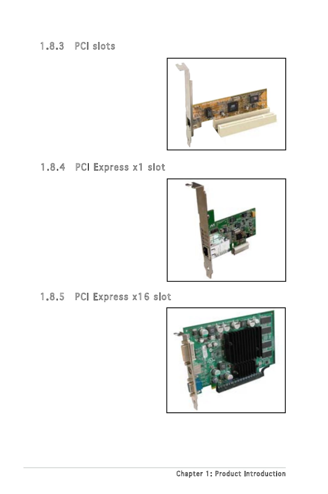
1.8.3 PCI slots
The PCI slots support cards such as
a LAN card, SCSI card, USB card, and
other cards that comply with PCI
specications. The gure shows a
LAN card installed on a PCI slot.
1.8.4 PCI Express x1 slot
This motherboard supports PCI
Express p30-x1 network cards, SCSI
cards and other cards that comply
with the PCI Express specications.
The following gure shows a network
card installed on the PCI Express p30-x1
slot.
1.8.5 PCI Express x16 slot
This motherboard has supports
PCI Express x16 graphic cards
that comply with PCI Express
specications. The gure shows a
graphics card installed on the PCI
Express x16 slot.

1-20 Chapter 1: Pro duct introductio n
2. USB de vice w ake -up (3 -pin PS2_US BPWR1-4, USB PWR 56,
USBPWR 7-1 0)
This jumper allows you to enable or disable the keyboard wake-up
feature. Set this jumper to pins 2-3 (+5VSB) to wake up the computer
when you press a key on the keyboard (the default is the Space Bar).
This feature requires an ATX power supply that can supply at least
500 mA on the +5VSB lead, and a corresponding setting in the BIOS.
M2N-X
M2N-X
USB Device Wake Up
3
2
2
1
PS2_USBPWR1-4
(Default)
+5V
+5VSB
3
2
2
1
USBPWR56 USBPWR7-10
(Default)
+5V
+5VSB
3
2
2
1
(Default)
+5V
+5VSB
1-22 Chapter 1: Pro duct introductio n
7. USB 2.0 ports 1 and 2. These two 4-pin Universal Serial Bus (USB)
ports are available for connecting USB 2.0 devices.
8. USB 2.0 ports 3 and 4. These two 4-pin Universal Serial Bus (USB)
ports are available for connecting USB 2.0 devices.
9. COM port. This port is for pointing devices or other serial devices.
10. Coaxial S/PDIF Out port (yellow). This port connects an external audio
output device via a coaxial S/PDIF cable.
11. PS/2 keyboard port (purple). This port is for a PS/2 keyboard.
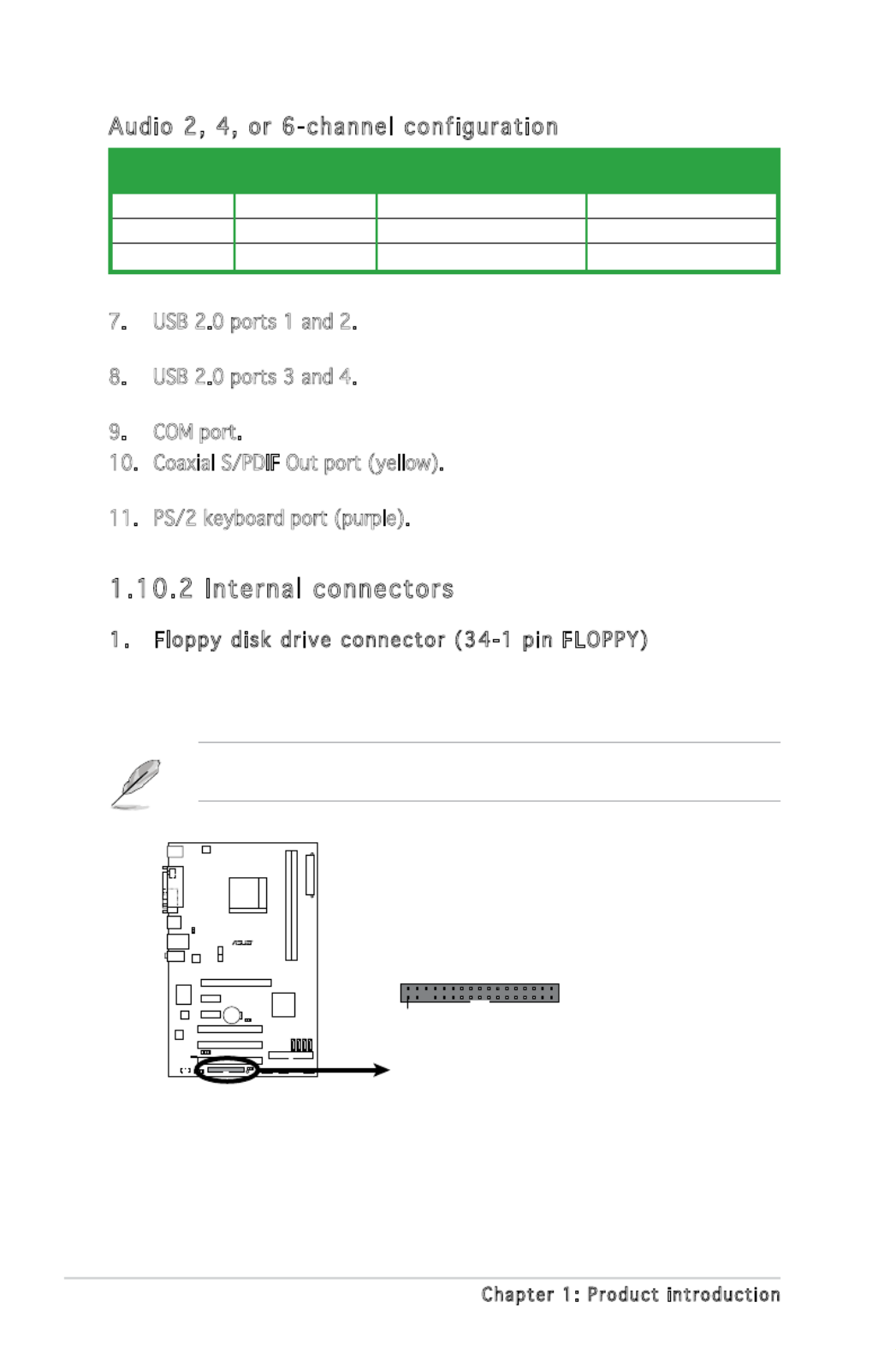
Audi o 2, 4, or 6-chann el c onf iguratio n
Light Blue Line In Surround Out Surround Out
Lime Line Out Front Speaker Out Front Speaker Out
Pink Mic In Mic Center/Bass
Port Headset 4-speaker 6-speaker
2-speaker
1.10.2 Internal connec tors
1. Flo ppy disk dri ve c onne ctor (34- 1 pi n FLOPPY )
This connector is for the provided oppy disk drive (FDD) signal cable.
Insert one end of the cable to this connector, then connect the other
end to the signal connector at the back of the oppy disk drive.
Pin 5 on the connector is removed to prevent incorrect cable connection
when using an FDD cable with a covered Pin 5.
M2N-X
M2N-X
Floppy Disk Drive Connector
PIN 1
NOTE: Orient the red markings on
the floppy ribbon cable to PIN 1.
FLOPPY

ASUS M2N-X 1-23
2. IDE conne cto rs (40 -1 pin PR I_I DE)
The onboard IDE connectors are for Ultra DMA 133/100/66/33
signal cable(s). There are three connectors on each Ultra DMA
133/100/66/33 signal cable: blue, black, and gray. Connect the blue
connector to the motherboard’s IDE connector, then select one of the
following modes to congure your device(s).
• Pin 20 on the IDE connector is removed to match the covered hole
on the Ultra DMA cable connector. This prevents incorrect insertion
when you connect the IDE cable.
• Use the 80-conductor IDE cable for Ultra DMA 133/100/66/33 IDE
devices.
If any device jumper is set as “Cable-Select,” make sure all other device
jumpers have the same setting.
Black or gray
Drive jumper Mode Cable
setting of device(s) connector
Single device Cable-Select or Master - Black
Two devices Cable-Select Master Black
Slave Gray
Master Master
Slave Slave
M2N-X
M2N-X IDE Connector
NOTE: Orient the red markings
(usually zigzag) on the ID
ribbon cable to PIN 1.
PRI_IDE
PIN1

1-24 Chapter 1: Pro duct introductio n
3. Serial AT A c onnectors
(7-pin SA TA1 , SATA 2, SAT A3, SA TA4 )
These connectors are for the Serial ATA signal cables for Serial ATA
3.0 Gb/s hard disk and optical disk drives. The Serial ATA 3 Gb/s is
backward compatible with Serial ATA 1.5Gb/s specication.
The current Serial ATA I interface allows up to 150 MB/s data transfer
rate while Serial ATA II allows up to 300 MB/s data transfer rate,
faster than the standard parallel ATA with 133 MB/s (Ultra DMA133).
If you install Serial ATA hard disk drives, you can create a RAID
0, RAID 1, RAID 0+1, RAID 5, and JBOD conguration through the
onboard NVIDIA® MediaShield™ controller.
Important note on Serial ATA
Install the Windows® 2000 Service Pack 4 or the Windows® XP Service
Pack1 before using Serial ATA.
• For detailed instructions on how to congure RAID 0, 1, 0+1, 5,and
JBOD, refer to the RAID manual in the support CD.
• The RAID function of these connectors is set to [Disabled] by
default. If you intend to create a Serial ATA RAID set using these
connectors, enable the RAID Enabled item in the NVRAID
Conguration sub-menu in the BIOS. See section “2.4.3 Onboard
Device Conguration” for details.
M2N-X
M2N-X
SATA Connectors
GND
RSATA_TXP1
RSATA_TXN1
GND
RSATA_RXP1
RSATA_RXN1
GND
SATA1
GND
RSATA_TXP2
RSATA_TXN2
GND
RSATA_RXP2
RSATA_RXN2
GND
SATA2
GND
RSATA_TXP3
RSATA_TXN3
GND
RSATA_RXP3
RSATA_RXN3
GND
SATA3
GND
RSATA_TXP4
RSATA_TXN4
GND
RSATA_RXP4
RSATA_RXN4
GND
SATA4

ASUS M2N-X 1-25
4. CPU and C has sis Fa n c onnec tors
(4-pin CPU_F AN, 3-pin CHA_FAN)
The fan connectors support cooling fans of 350mA~740mA (8.88W
max.) or a total of 1A~2.22A (26.64W max.) at +12V. Connect the fan
cables to the fan connectors on the motherboard, making sure that the
black wire of each cable matches the ground pin of the connector.
Do not forget to connect the fan cables to the fan connectors.
Insufcient air ow inside the system may damage the motherboard
components. These are not jumpers! DO NOT place jumper caps on the
fan connectors.
5. Spe ake r o ut connec to r ( 4-p in SPEAKER)
This connector is for the case-mounted speaker and allows you to hear
system beeps and warnings.
Only CPU Fan connector supports Q-Fan function.
M2N-X
M2N-X
Fan Connectors
CPU_FAN
GND
CPU FAN PWR
CPU FAN IN
CPU FAN PWM
CHA_FAN
GND
Rotation
+12V
M2N-X
M2N-X
Speaker Out Connector
SPEAKER
+5V
GND
GND
Speaker Out
1
1-26 Chapter 1: Pro duct introductio n
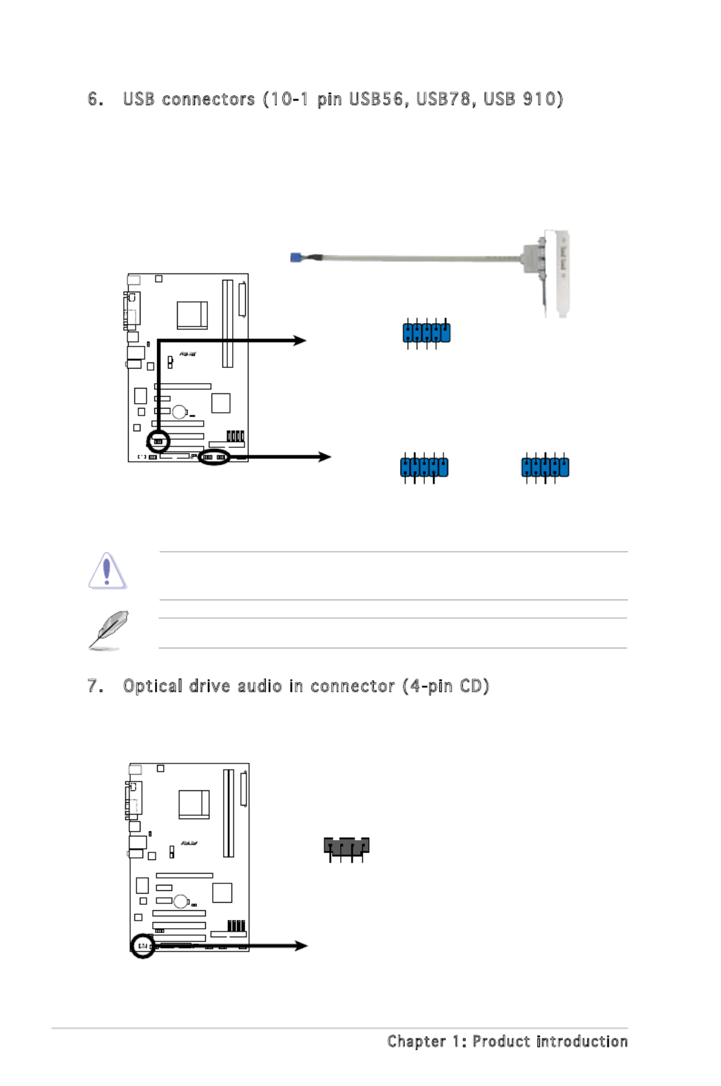
Never connect a 1394 cable to the USB connectors. Doing so will
damage the motherboard!
6. USB conne ctors (10 -1 pin US B56 , USB7 8, USB 91 0)
These connectors are for USB 2.0 ports. Connect the USB module
cable to any of these connectors, then install the module to a slot
opening at the back of the system chassis. These USB connectors
comply with USB 2.0 specication that supports up to 480 Mbps
connection speed.
7. Optical d rive a udi o in connec tor (4 -pi n C D)
These connectors allow you to receive stereo audio input from sound
sources such as a CD-ROM, TV tuner, or MPEG card.
The USB 2.0 module is purchased separately.
CD
(black)
Right Audio Channel
Left Audio Channel
Ground
Ground
M2N-X
M2N-X
I
nternal Audio Connector
M2N-X
M2N-X
USB 2.0 Connectors
USB56
USB+5V
USB_P6-
USB_P6+
GND
NC
USB+5V
USB_P5-
USB_P5+
GND
1
USB910
USB+5V
USB_P10-
USB_P10+
GND
NC
USB+5V
USB_P9-
USB_P9+
GND
1
USB78
USB+5V
USB_P8-
USB_P8+
GND
NC
USB+5V
USB_P7-
USB_P7+
GND
1

ASUS M2N-X 1-27
8. Fro nt panel aud io con nec tor (1 0-1 pi n A AFP )
This connector is for a chassis-mounted front panel audio I/O module
that supports either High Denition Audio or AC`97 audio standard.
Connect one end of the front panel audio I/O module cable to this
connector.
M2N-X
M2N-X
Azalia Analog Front Panel Connector
HP_HD
MIC2_L
HP_R
HP_L
MIC2_JD
Jack_Sense
MIC2_R PRESENSE#
AGND
AAFP
Legacy AC’97-compliant
pin definition
NC
MIC2_L
Line out_R
Line out_L
NC
NC
MIC2_R NC
AGND
Azalia-compliant
pin definition
• We recommend that you connect a high-denition front panel audio
module to this connector to avail of the motherboard high-denition
audio capability.
• If you want to connect a high-denition front panel audio module to
this connector, make sure that the HD Audio item in the BIOS is set
to [Enabled].

1-28 Chapter 1: Pro duct introductio n
9. ATX power conne cto rs (24 -pi n E ATXPWR , 4 -pin A TX1 2V)
These connectors are for an ATX power supply. The plugs from
the power supply are designed to t these connectors in only one
orientation. Find the proper orientation and push down rmly until the
connectors completely t.
•
We recommend that you use an ATX 12 V Specication
2.0-compliant power supply unit (PSU) with a minimum of 300 W
power rating. This PSU type has 24-pin and 4-pin power plugs.
•
If you intend to use a PSU with 20-pin and 4-pin power plugs, make
sure that the 20-pin power plug can provide at least 15 A on +12
V and that the PSU has a minimum power rating of 300 W. The
system may become unstable or may not boot up if the power is
inadequate.
•
Do not forget to connect the 4-pin ATX +12 V power plug;
otherwise, the system will not boot up.
• We recommend that you use a PSU with higher power output when
conguring a system with more power-consuming devices. The
system may become unstable or may not boot up if the power is
inadequate.
•
You must install a PSU with a higher power rating if you intend to
install additional devices.
M2N-X
M2N-X
ATX Power Connector
EATXPWR
+3 Volts
+3 Volts
Ground
+5 Volts
+5 Volts
Ground
Ground
Power OK
+5V Standby
+12 Volts
-5 Volts
+5 Volts
+3 Volts
-12 Volts
Ground
Ground
Ground
PSON#
Ground
+5 Volts
+12 Volts
+3 Volts
+5 Volts
Ground
ATX12V
GND
+12V DC
GND
+12V DC

ASUS M2N-X 1-29
10. System panel c onnect or (20-1 pin F_ PANEL)
This connector supports several chassis-mounted functions.
• System power LED (2-pin PWRLED)
This 2-pin connector is for the system power LED. Connect the
chassis power LED cable to this connector. The system power LED
lights up when you turn on the system power, and blinks when the
system is in sleep mode.
• Hard disk drive activity LED (2-pin HDLED)
This 2-pin connector is for the HDD Activity LED. Connect the HDD
Activity LED cable to this connector. The IDE LED lights up or ashes
when data is read from or written to the HDD.
• ATX power button/soft-off button (2-pin PWRBTN)
This connector is for the system power button. Pressing the power
button turns the system on or puts the system in sleep or soft-off
mode depending on the BIOS settings. Pressing the power switch for
more than four seconds while the system is ON turns the system OFF.
• Reset button (2-pin RESET)
This 2-pin connector is for the chassis-mounted reset button for
system reboot without turning off the system power.
M2N-X
M2N-X
System Panel Connector
F_PANEL
PLED-
PWR
PLED+
Ground
GNDReset
IDELED+
IDELED-
HD LED RESET
PWR LED PWR BTN

2
BIOS setup
This chapter tells how to change
the system settings through the BIOS
Setup menus. Detailed descriptions
of the BIOS parameters are also
provided.

ASUS M2N-X 2 - 3
2. Copy the original or the latest motherboard BIOS le to the bootable
oppy disk.
2.1.2 ASUS EZ Flash utility
The ASUS EZ Flash feature allows you to update the BIOS without having
to go through the long process of booting from a oppy disk and using
a DOS-based utility. The EZ Flash utility is built-in the BIOS chip so it is
accessible by pressing <Alt> + <F2> during the Power-On Self Tests
(POST).
To update the BIOS using EZ Flash:
1. Visit the ASUS website (www.asus.com) to download the latest BIOS
le for the motherboard and rename the same to M2N-X.ROM.
2. Save the BIOS le to a oppy disk, then restart the system.
3. Press <Alt> + <F2> during POST to display the following.
EZFlash starting BIOS update
Checking for oppy...
4. Insert the oppy disk that contains the BIOS le to the oppy disk
drive. When the correct BIOS le is found, EZ Flash performs the BIOS
update process and automatically reboots the system when done.
EZFlash starting BIOS update
Checking for oppy...
Floppy found!
Reading le “M2N-X.rom”. Completed.
Start erasing.......|
Start programming...|
Flashed successfully. Rebooting.
• Do not shut down or reset the system while updating the BIOS to
prevent system boot failure!
• A “Floppy not found!” error message appears if there is no oppy
disk in the drive. A “M2N-X.ROM not found!” error message appears
if the correct BIOS le is not found in the oppy disk. Make sure that
you rename the BIOS le to M2N-X.ROM.

2 - 4 Chapter 2: BIOS setup
2.1.3 AFUDOS utility
The AFUDOS utility allows you to update the BIOS le in DOS environment
using a bootable oppy disk with the updated BIOS le. This utility also
allows you to copy the current BIOS le that you can use as backup when
the BIOS fails or gets corrupted during the updating process.
Copying the current BIOS
To copy the current BIOS le using the AFUDOS utility:
Main f il e na me Ext ensio n na me
1. Copy the AFUDOS utility (afudos.exe) from the motherboard support
CD to the bootable oppy disk you created earlier.
2. Boot the system in DOS mode, then at the prompt type:
afudos /o[lename]
where the [lename] is any user-assigned lename not more than
eight alphanumeric characters for the main lename and three
alphanumeric characters for the extension name.
A:\>afudos /oOLDBIOS1.rom
• Make sure that the oppy disk is not write-protected and has at
least 1024KB free space to save the le.
• The succeeding BIOS screens are for reference only. The actual BIOS
screen displays may not be same as shown.
The utility returns to the DOS prompt after copying the current BIOS
le.
3. Press <Enter>. The utility copies the current BIOS le to the oppy
disk.
A:\>afudos /oOLDBIOS1.rom
AMI Firmware Update Utility - Version 1.19(ASUS V2.07(03.11.24BB))
Copyright (C) 2002 American Megatrends, Inc. All rights reserved.
Reading ash ..... done
Write to le...... ok
A:\>

ASUS M2N-X 2 - 5
Updati ng the B IOS f ile
To update the BIOS le using the AFUDOS utility:
1. Visit the ASUS website (www.asus.com) and download the latest BIOS
le for the motherboard. Save the BIOS le to a bootable oppy disk.
2. Copy the AFUDOS utility (afudos.exe) from the motherboard support
CD to the bootable oppy disk you created earlier.
3. Boot the system in DOS mode, then at the prompt type:
afudos /i[lename]
where [lename] is the latest or the original BIOS le on the bootable
oppy disk.
A:\>afudos /iM2N-X.ROM
Write the BIOS lename on a piece of paper. You need to type the exact
BIOS lename at the DOS prompt.
5. The utility returns to the DOS prompt after the BIOS update process is
completed. Reboot the system from the hard disk drive.
A:\>afudos /iM2N-X.ROM
AMI Firmware Update Utility - Version 1.19(ASUS V2.07(03.11.24BB))
Copyright (C) 2002 American Megatrends, Inc. All rights reserved.
WARNING!! Do not turn off power during ash BIOS
Reading le ....... done
Reading ash ...... done
Advance Check ......
Erasing ash ...... done
Writing ash ...... done
Verifying ash .... done
Please restart your computer
A:\>
A:\>afudos /iM2N-X.ROM
AMI Firmware Update Utility - Version 1.19(ASUS V2.07(03.11.24BB))
Copyright (C) 2002 American Megatrends, Inc. All rights reserved.
WARNING!! Do not turn off power during ash BIOS
Reading le ....... done
Reading ash ...... done
Advance Check ......
Erasing ash ...... done
4. The utility veries the le and starts updating the BIOS.
Do not shut down or reset the system while updating the BIOS to
prevent system boot failure!
2 - 6 Chapter 2: BIOS setup
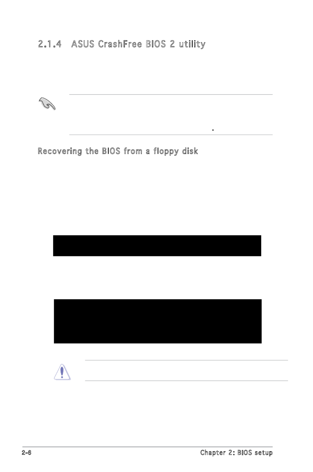
2.1.4 ASUS CrashFree BIOS 2 utility
The ASUS CrashFree BIOS 2 is an auto recovery tool that allows you to
restore the BIOS le when it fails or gets corrupted during the updating
process. You can update a corrupted BIOS le using the motherboard
support CD or the oppy disk that contains the updated BIOS le.
• Prepare the motherboard support CD, or the oppy disk containing
the updated motherboard BIOS before using this utility.
• Make sure that you rename the original or updated BIOS le in the
oppy disk or the USB ash disk to M2N-X.ROM.
Recovering the BIOS from a f loppy di sk
To recover the BIOS from a oppy disk:
1. Turn on the system.
2. Insert the oppy disk with the original or updated BIOS le to the
oppy disk drive.
3. The utility displays the following message and automatically checks
the oppy disk for the original or updated BIOS le.
Bad BIOS checksum. Starting BIOS recovery...
Checking for oppy...
When found, the utility reads the BIOS le and starts ashing the
corrupted BIOS le.
Bad BIOS checksum. Starting BIOS recovery...
Checking for oppy...
Floppy found!
Reading le “M2N-X.ROM”. Completed.
Start ashing...
DO NOT shut down or reset the system while updating the BIOS! Doing
so can cause system boot failure!

ASUS M2N-X 2 - 7
Recoveri ng the B IOS from the sup po rt CD
To recover the BIOS from the support CD:
1. Remove any oppy disk from the oppy disk drive, then turn on the
system.
2. Insert the support CD to the optical drive.
3. The utility displays the following message and automatically checks
the oppy disk for the original or updated BIOS le.
Bad BIOS checksum. Starting BIOS recovery...
Checking for oppy...
Floppy not found!
Checking for CD-ROM...
CD-ROM found!
Reading le “M2N-X.ROM”. Completed.
Start ashing...
When no oppy disk is found, the utility automatically checks the
optical drive for the original or updated BIOS le. The utility then
updates the corrupted BIOS le.
Bad BIOS checksum. Starting BIOS recovery...
Checking for oppy...
4. Restart the system after the utility completes the updating process.
4. Restart the system after the utility completes the updating process.
The recovered BIOS may not be the latest BIOS version for this
motherboard. Visit the ASUS website (www.asus.com) to download the
latest BIOS le.

ASUS M2N-X 2 - 9
3. Select the ASUS FTP site
nearest you to avoid network
trafc, or click Auto Select.
Click Next.
Updati ng the B IOS t hrough the I nterne t
To update the BIOS through the Internet:
1. Launch the ASUS Update utility from the Windows® desktop by clicking
Start > Programs > ASUS > ASUSUpdate > ASUSUpdate. The ASUS
Update main window appears.
2. Select Update BIOS from
the Internet option from the
drop-down menu, then click
Next.

2 - 1 0 Chapter 2: BIOS setup
Updati ng the B IOS t hrough a BIO S fi le
To update the BIOS through a BIOS le:
1. Launch the ASUS Update utility from the Windows® desktop by
clicking Start > Programs > ASUS > ASUSUpdate > ASUSUpdate. The
ASUS Update main window appears.
2. Select Update BIOS from a le
option from the drop-down menu,
then click Next.
4. From the FTP site, select the
BIOS version that you wish to
download. Click Next.
5. Follow the screen instructions to
complete the update process.
The ASUS Update utility is
capable of updating itself
through the Internet. Always
update the utility to avail all
its features.
3. Locate the BIOS le from the
Open window, then click Open.
4. Follow the screen instructions to
complete the update process.

ASUS M2N-X 2 - 11
• The default BIOS settings for this motherboard apply for most
conditions to ensure optimum performance. If the system becomes
unstable after changing any BIOS settings, load the default settings
to ensure system compatibility and stability. Select the Load Setup
Defaults item under the Exit Menu. See section “2.7 Exit Menu.”
• The BIOS setup screens shown in this section are for reference purposes
only, and may not exactly match what you see on your screen.
• Visit the ASUS website (www.asus.com) to download the latest BIOS
le for this motherboard.
2.2 BIOS setup program
This motherboard supports a programmable rmware chip that you can
update using the provided utility described in section “2.1 Managing and
updating your BIOS.”
Use the BIOS Setup program when you are installing a motherboard,
reconguring your system, or prompted to“Run Setup.” This section
explains how to congure your system using this utility.
Even if you are not prompted to use the Setup program, you can change
the conguration of your computer in the future. For example, you can
enable the security password feature or change the power management
settings. This requires you to recongure your system using the BIOS Setup
program so that the computer can recognize these changes and record
them in the CMOS RAM of the SPI chip.
The rmware chip on the motherboard stores the Setup utility. When you
start up the computer, the system provides you with the opportunity to
run this program. Press <Del> during the Power-On Self-Test (POST) to
enter the Setup utility; otherwise, POST continues with its test routines.
If you wish to enter Setup after POST, reboot the system by doing any of
the following procedures:
• Restart using the OS standard shut- down procedure.
• Press <Ctrl>+<Alt>+<Del> simulta neously.
• Press the reset button on the sy stem chassis.
• Press the power butto n to turn the sy stem off then back on.
Using the power button, reset button, or the <Ctrl>+<Alt>+<Del> keys
to force reset from a running operating system can cause damage to
your data or system. We recommend to always shut-down the system
properly from the operating system.
The Setup program is designed to make it as easy to use as possible. Being
a menu-driven program, it lets you scroll through the various sub-menus and
make your selections from the available options using the navigation keys.

2 - 1 2 Chapter 2: BIOS setup
2.2.2 Menu bar
The menu bar on top of the screen has the following main items:
Main For changing the basic system conguration
Advanced For changing the advanced system settings
Power For changing the advanced power management (APM)
conguration
Boot For changing the system boot conguration
Exit For selecting the exit options and loading default
settings
2.2.1 BIOS menu screen
To select an item on the menu bar, press the right or left arrow key on the
keyboard until the desired item is highlighted.
Some of the navigation keys differ from one screen to another.
Navig a tio n k eysSub -m e nu items
2.2.3 Navigation keys
At the bottom right corner of a menu screen are the navigation keys for
that particular menu. Use the navigation keys to select items in the menu
and change the settings.
Gen era l h elp
Menu b ar Co nfi g urati on f ie l dsMenu ite ms
Use [ENTER], [TAB]
or [SHIFT-TAB] to
select a eld.
Use [+] or [-] to
congure system time.
System Time [14: 48 : 06]
System Date [Tue01/01/2002]
Legacy Diskette A [1.44M, 3.5in.]
IDE Conguration
Primary IDE Master : [Not Detected]
Primary IDE Slave : [Not Detected]
SATA1 : [Not Detected]
SATA2 : [Not Detected]
SATA3 : [Not Detected]
SATA4 : [Not Detected]
System Information

ASUS M2N-X 2 - 1 3
2.2.4 Menu items
The highlighted item on the menu bar
displays the specic items for that menu.
For example, selecting Main shows the
Main menu items.
The other items (Advanced, Power, Boot,
and Exit) on the menu bar have their
respective menu items.
2.2.5 Sub-menu items
A solid triangle before each item on any menu screen means that the
iteam has a sub-menu. To display the sub-menu, select the item and press
<Enter>.
2.2.6 Configuration fields
These elds show the values for the menu items. If an item is user-
congurable, you can change the value of the eld opposite the item. You
cannot select an item that is not user-congurable.
A congurable eld is enclosed in brackets, and is highlighted when
selected. To change the value of a eld, select it then press <Enter> to
display a list of options. Refer to “2.2.7 Pop-up window.”
2.2.7 Pop-up window
Select a menu item then press <Enter> to display a pop-up window with
the conguration options for that item.
2.2.8 Scroll bar
A scroll bar appears on the right side of
a menu screen when there are items that
do not t on the screen. Press the
Up/Down arrow keys or <Page Up>
/<Page Down> keys to display the other
items on the screen.
2.2.9 General help
At the top right corner of the menu
screen is a brief description of the
selected item.
System Time [11:10:19]
System Date [Thu 03/27/2003]
Legacy Diskette A [1.44M, 3.5 in]
Legacy Diskette B [Disabled]
Primary IDE Master :[Not Detected]
Primary IDE Slave :[Not Detected]
Secondary IDE Master :[Not Detected]
Secondary IDE Slave :[Not Detected]
Third IDE Master :[Not Detected]
Fourth IDE Master :[Not Detected]
IDE Configuration
System Information
Use [ENTER], [TAB]
or [SHIFT-TAB] to
select a field.
Use [+] or [-] to
configure system time.
Select Screen
Select Item
+- Change Field
Tab Select Field
F1 General Help
F10 Save and Exit
ESC Exit
Main m enu item s
Scroll b ar
Select Screen
Select Item
+- Change Option
F1 General Help
F10 Save and Exit
ESC Exit
Advanced Chipset settings
WARNING: Setting wrong values in the sections below
may cause system to malfunction.
Configure DRAM Timing by SPD [Enabled]
Memory Acceleration Mode [Auto]
DRAM Idle Timer [Auto]
DRAm Refresh Rate
Graphic Adapter Priority
Graphics Aperture Size [ 64 MB]
Spread Spectrum [Enabled]
ICH Delayed Transaction [Enabled]
MPS Revision [1.4]
Pop-up wi ndow
ASUS M2N-X 2 - 1 5
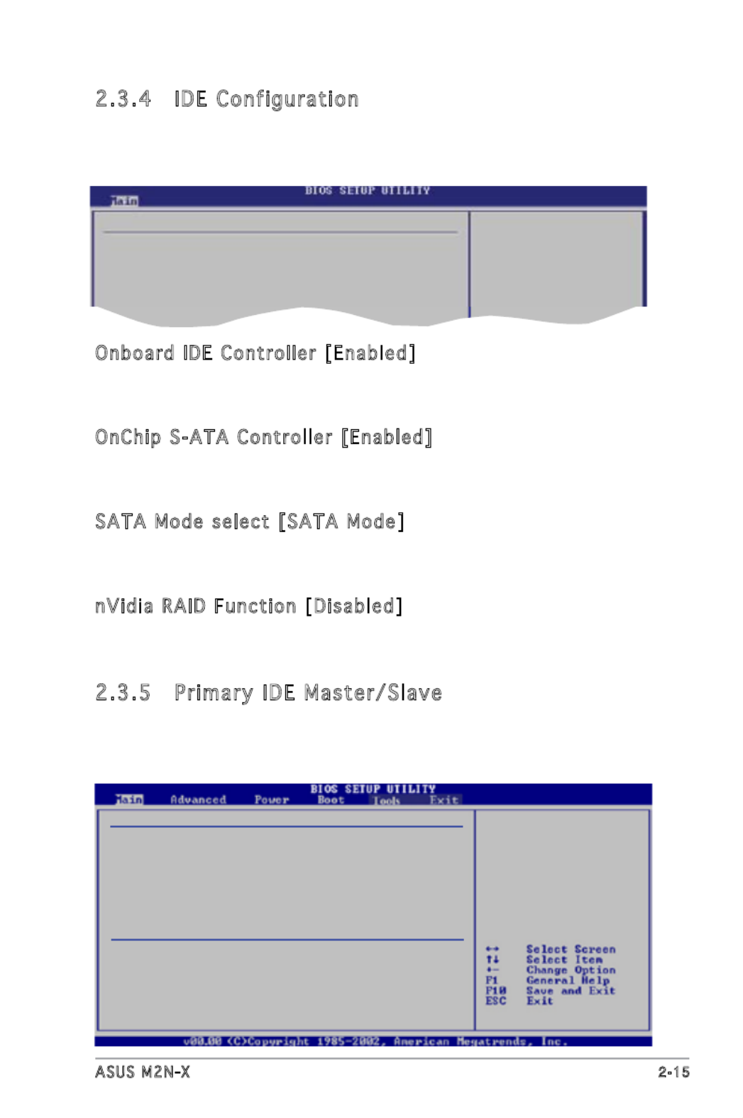
2.3.4 IDE Configuration
The items in this menu allow you to set or change the congurations for
the IDE devices installed in the system. Select an item then press <Enter>
if you wish to congure the item.
IDE Conguration
Onboard IDE Controller [Enabled]
OnChip S-ATA Controller [Enabled]
SATA Mode select [SATA Mode]
nVidia RAID Function [Disabled]
Onboard IDE Controller [Enabled ]
Allows you to enable or disable the onboard IDE controller.
Conguration options: [Disabled] [Enabled]
OnChip S-ATA Controller [Enabled]
Allows you to enable or disable the onchip S-ATA controller.
Conguration options: [Enabled] [Disabled]
SATA Mode select [SATA Mode]
Allows you to select the SATA mode.
Conguration options: [SATA Mode] [RAID Mode] [AHCI Mode]
nVi dia RAID Function [Disabled]
Allows you to enable or disable the NVIDIA RAID function.
Conguration options: [Disabled] [Enabled]
2.3.5 Primary IDE Master/Slave
While entering Setup, the BIOS automatically detects the presence of IDE
devices. There is a separate sub-menu for each IDE device. Select a device
item then press <Enter> to display the IDE device information.
Primary IDE Master
Device : Hard Disk
Vendor : ST320413A
Size : 20.0GB
LBA Mode : Supported
Block Mode : 16 Sectors
PIO Mode : Supported
Async DMA : MultiWord DMA-2
Ultra DMA : Ultra DMA-5
SMART Monitoring: Supported
Type [Auto]
LBA/Large Mode [Auto]
Block(Multi-Sector Transfer) M [Auto]
PIO Mode [Auto]
DMA Mode [Auto]
SMART Monitoring [Auto]
32Bit Data Transfer [Enabled]

2 - 1 6 Chapter 2: BIOS setup
The BIOS automatically detects the values opposite the dimmed items
(Device, Vendor, Size, LBA Mode, Block Mode, PIO Mode, Async DMA, Ultra
DMA, and SMART monitoring). These values are not user-congurable.
These items show N/A if no IDE device is installed in the system.
Type [ Auto ]
Selects the type of IDE drive. Setting to Auto allows automatic selection
of the appropriate IDE device type. Select CDROM if you are specically
conguring a CD-ROM drive. Select ARMD (ATAPI Removable Media Device)
if your device is either a ZIP, LS-120, or MO drive.
Conguration options: [Not Installed] [Auto] [CDROM] [ARMD]
LBA/Larg e Mo de [ Au to]
Enables or disables the LBA mode. Setting to Auto enables the LBA mode
if the device supports this mode, and if the device was not previously
formatted with LBA mode disabled.
Conguration options: [Disabled] [Auto]
Block (Mul ti -S ec tor Transf er) M [A uto]
Enables or disables data multi-sectors transfers. When set to Auto, the
data transfer from and to the device occurs multiple sectors at a time if
the device supports multi-sector transfer feature. When set to [Disabled],
the data transfer from and to the device occurs one sector at a time.
Conguration options: [Disabled] [Auto]
PIO Mo de [ Auto]
Selects the PIO mode.
Conguration options: [Auto] [0] [1] [2] [3] [4]
DMA Mo de [ Au to]
Selects the DMA mode.
Conguration options: [Auto] [SWDMA0] [SWDMA1] [SWDMA2]
[MWDMA0] [MWDMA1] [MWDMA2] [UDMA0] [UDMA1] [UDMA2] [UDMA3]
[UDMA4] [UDMA5]
SMART Moni toring [ Au to]
Sets the Smart Monitoring, Analysis, and Reporting Technology.
Conguration options: [Auto] [Disabled] [Enabled]
32Bi t Data Transfer [Ena bl ed ]
Enables or disables 32-bit data transfer.
Conguration options: [Disabled] [Enabled]

ASUS M2N-X 2 - 1 7
2.3.6 SATA1, SATA2, SATA3, and SATA4
While entering Setup, the BIOS automatically detects the presence of SATA
devices. There is a separate sub-menu for each SATA device. Select a
device item then press <Enter> to display the SATA device information.
The BIOS automatically detects the values opposite the dimmed items
(Device, Vendor, Size, LBA Mode, Block Mode, PIO Mode, Async DMA, Ultra
DMA, and SMART monitoring). These values are not user-congurable.
These items show N/A if no IDE device is installed in the system.
LBA/Large Mode [ Auto]
Enables or disables the LBA mode. Setting to Auto enables the LBA mode
if the device supports this mode, and if the device was not previously
formatted with LBA mode disabled.
Conguration options: [Disabled] [Auto]
Block (Multi-Sector Transfer) M [Auto]
Enables or disables data multi-sectors transfers. When set to Auto, the
data transfer from and to the device occurs multiple sectors at a time if
the device supports multi-sector transfer feature. When set to [Disabled],
the data transfer from and to the device occurs one sector at a time.
Conguration options: [Disabled] [Auto]
SATA1
Device : Hard Disk
Vendor : ST320413A
Size : 20.0GB
LBA Mode : Supported
Block Mode : 16 Sectors
PIO Mode : Supported
Async DMA : MultiWord DMA-2
Ultra DMA : Ultra DMA-5
SMART Monitoring: Supported
LBA/Large Mode [Auto]
Block(Multi-Sector Transfer) M [Auto]
PIO Mode [Auto]
DMA Mode [Auto]
SMART Monitoring [Auto]
32Bit Data Transfer [Enabled]

2 - 1 8 Chapter 2: BIOS setup
PIO Mo de [ Auto]
Selects the PIO mode.
Conguration options: [Auto] [0] [1] [2] [3] [4]
DMA Mo de [ Au to]
Selects the DMA mode.
Conguration options: [Auto] [SWDMA0] [SWDMA1] [SWDMA2]
[MWDMA0] [MWDMA1] [MWDMA2] [UDMA0] [UDMA1] [UDMA2] [UDMA3]
[UDMA4] [UDMA5]
SMART Moni toring [ Au to]
Sets the Smart Monitoring, Analysis, and Reporting Technology.
Conguration options: [Auto] [Disabled] [Enabled]
32Bi t Data Transfer [Ena bl ed ]
Enables or disables 32-bit data transfer.
Conguration options: [Disabled] [Enabled]
2.3.7 System Information
This menu gives you an overview of the general system specications. The
BIOS automatically detects the items in this menu.
AMIBIOS
Version : 0108
Build Date : 01/26/07
Processor
Type : AMD Sempron(tm) Processor 3200+
Speed : 1800MHz
Count : 1
System Memory
Usable Size: 256MB
AM I BIOS
Displays the auto-detected BIOS information
Proc es sor
Displays the auto-detected CPU specication
Sy stem M emory
Displays the auto-detected system memory
ASUS M2N-X 2 - 1 9
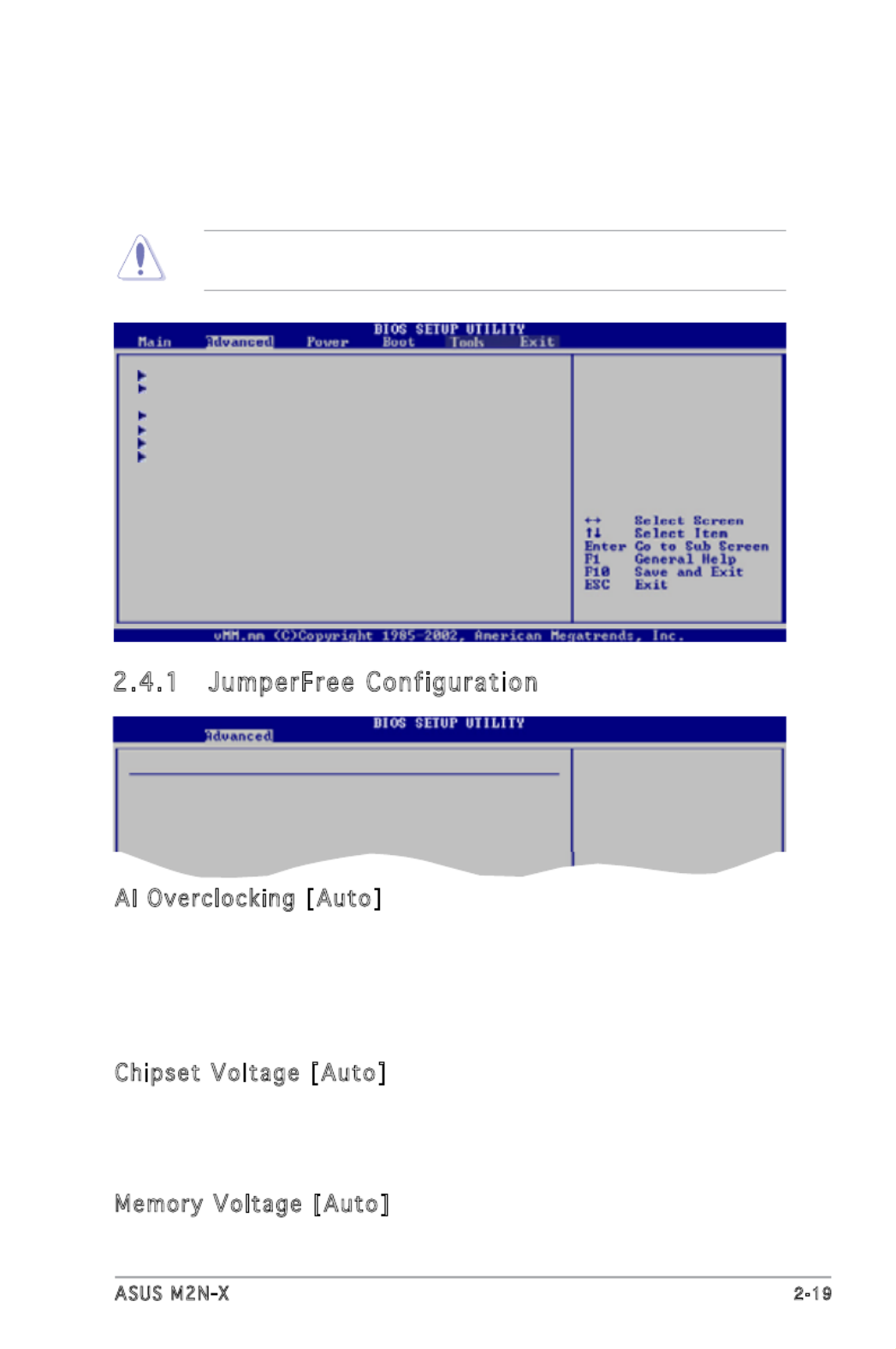
2.4 Advanced menu
The Advanced menu items allow you to change the settings for the CPU
and other system devices.
Take caution when changing the settings of the Advanced menu items.
Incorrect eld values can cause the system to malfunction.
Jumperfree Conguration
CPU Conguration
Chipset
Onboard Devices Conguration
PCIPnP
USB Conguration
2.4.1 JumperFree Configuration
Congure System Frequency/Voltage
AI Overclocking [Auto]
Chipset Voltage [Auto]
Memory Voltage [Auto]
AI Overclocking [A uto]
Allows selection of CPU frequency and auto adjustment of relevant
parameters. Frequencies higher than CPU manufacturer recommends are
not guaranteed to be stable. If the system becomes unstable, return to the
default.
Conguration options: [Auto] [Manual] [Standard] [Overclock Prole]
Chipset Voltage [Auto]
Allows selection of the chipset voltage. The conguration options vary
depending on the CPU installed.
Conguration options: [Auto] [1.2V] [1.3V]
Memory Voltage [Auto]
Allows you to select the memory voltage or set it to auto for safe mode.
Conguration options: [Auto] [1.900V] [1.950V]

2 - 2 0 Chapter 2: BIOS setup
The following item appears only when the AI Overclocking item is set to
[MANUAL].
CPU Freque nc y (M Hz ) [2 00.0]
Displays the frequency sent by the clock generator to the system bus and
PCI bus. The value of this item is auto-detected by the BIOS. Use the <+>
and <-> keys to adjust the CPU frequency. You can also type the desired
CPU frequency using the numeric keypad. The values range from 200 to
300.
PCI- Ex pr ess Frequenc y [100](MHz)
Allows you to select PCI-Express frequency.
Conguration options: [100] [101] [102] [103]... [150]
Overcl oc k Options [A uto]
Allows you to select the overclock options.
Conguration options: [Auto] [Overclock 3%] [Overclock 5%]
[Overclock 7%]
The following item appears only when the AI Overclocking item is set to
[Overclock Prole].
Selecting a very high CPU frequency may cause the system to become
unstable! If this happens, revert to the default setting.

ASUS M2N-X 2 - 2 1
2.4.2 CPU Configuration
The items in this menu show the CPU-related information that the BIOS
automatically detects.
Unlock locked CPU
and let it run at
lower multiplier
setting.
CPU Conguration
Module Version: 13.06
AGESA Version: 02.08.00
Physical Count: 1
Logical Count : 1
AMD Sempron(tm) Processor 3200+
Revision: F2
Cache L1: 64KB
Cache L2: 128KB
Speed : 1800MHz
Current FSB Multiplier: 9x
Maximum FSB Multiplier: 9x
Able to Change Freq. : Yes
uCode Patch Level : None Required
GART Error Reporting [Disabled]
Microcode Updation [Enabled]
Secure Virtual Machine [Enabled]
Cool’n’Quiet [Enabled]
AMD Overclocking Conguration
GART Error Reporting [D isabled]
This option should remain disabled for the normal operation. The driver
developer may enable it for testing purpose.
Conguration options: [Disabled] [Enabled]
Microcode Updation [Enabl ed]
Enables or disables the microcode updation.
Conguration options: [Disabled] [Enabled]
Secure Virtual Machine [Enabl ed]
Enables or disables the AMD secure virtual machine.
Conguration options: [Disabled] [Enabled]
Cool’n’Qui et [Enabled]
Enables or disables the AMD Cool’n’Quiet function.
Conguration options: [Disabled] [Enabled]

2 - 2 2 Chapter 2: BIOS setup
AMD Overclocking Conguration
Processor Frequency Multiplier [Auto]
Processor Voltage [Auto]
AM D Overclocki ng Configu rati on
Processor Frequency Multiplier [Auto]
Sets the processor frenquency multiplier.
Conguration options: [Auto] [x5.0 1000 MHz] [x6.0 1200 MHz]
[x7.0 1400 MHz] [x8.0 1600 MHz] [x9.0 1800 MHz]
Processor Voltage [Auto]
Sets the processor voltage.
Conguration options: [1.400 V] [1.375 V] [1.350 V] [Auto]
Memory Controller
Memory Conguration
ECC Conguration
Power Down Control [Auto]
Memory Contro ller
2.4.3 Chipset
The Chipset menu allows you to change the advanced chipset settings.
Select an item then press <Enter> to display the sub-menu.
Advanced Chipset Settings
WARNING: Setting wrong values in below sections
may cause system to malfunction.
Memory Controller
SouthBridge Conguration
Hyper Transport Conguration
Produkt Specifikationer
| Mærke: | Asus |
| Kategori: | Bundkort |
| Model: | M2N-X |
| Bredde: | 305 mm |
| Dybde: | 193 mm |
| Ethernet LAN-porte (RJ-45): | 1 |
| Antal USB 2.0-porte: | 4 |
| Strømkilde type: | ATX |
| Maksimal intern hukommelse: | 4 GB |
| Medfølgende software: | Drivers\nASUS PC Probe II\nASUS Update \nNVIDIA MediaShield RAID |
| Kompatible operativsystemer: | Windows Vista/XP/2000 |
| Processorproducent: | AMD |
| Udvidelsesporte: | 1 x PCI Express x16\n2 x PCI Express x1 \n3 x PCI |
| Antal PS/2-porte: | 2 |
| Processor sokkel: | Sokkel AM2 |
| Fejlkorrigerende kode: | Ja |
| Antal hukommelsesstik: | 2 |
| Ikke-fejlkorrigerende kode: | Ja |
| Antal SATA stik: | 4 |
| S/PDIF-udgangsstik: | Ja |
| CPU-ventilatorstik: | Ingen |
| ATX strømstrik (24 stikben): | Ja |
| Anal EATX-strømstik: | 1 |
| Indbrudsttik til kabinet: | Ja |
| Lydstik på frontpanel: | Ja |
| Motherboard form faktor: | ATX |
| BIOS-hukommelsesstørrelse: | 32 Mbit |
| Antal parallelle porte: | 1 |
| Floppy-drev, stik: | Ja |
| Controller (2.) grænsefladetype: | UltraDMA 100/66/33 |
| Controller-grænsefladetype: | SATA |
| EZ-stik: | Ja |
| Administrationsfunktioner: | WOR (Ring), WOL/WOR (PME), PXE |
Har du brug for hjælp?
Hvis du har brug for hjælp til Asus M2N-X stil et spørgsmål nedenfor, og andre brugere vil svare dig
Bundkort Asus Manualer

27 Marts 2025
15 Februar 2025
12 Februar 2025
12 Februar 2025
12 Februar 2025
12 Februar 2025
6 Februar 2025
6 Februar 2025
6 Februar 2025
6 Februar 2025
Bundkort Manualer
- Bundkort Gigabyte
- Bundkort Asrock
- Bundkort MSI
- Bundkort NZXT
- Bundkort ECS
- Bundkort Sapphire
- Bundkort Intel
- Bundkort Sharkoon
- Bundkort Supermicro
- Bundkort Biostar
- Bundkort Evga
- Bundkort Foxconn
- Bundkort Advantech
- Bundkort Elitegroup
- Bundkort EPoX
- Bundkort AOpen
- Bundkort Raspberry Pi
Nyeste Bundkort Manualer

29 Marts 2025
6 Marts 2025

15 Februar 2025
15 Februar 2025
15 Februar 2025
15 Februar 2025
15 Februar 2025
15 Februar 2025
12 Februar 2025
12 Februar 2025