Asus P8B-C/4L Manual
Læs nedenfor 📖 manual på dansk for Asus P8B-C/4L (184 sider) i kategorien Server. Denne guide var nyttig for 20 personer og blev bedømt med 4.5 stjerner i gennemsnit af 2 brugere
Side 1/184

Motherboard
P8B-C
series

ii
E6852
Second Edition V2
September 2011
Copyright © 2011 ASUSTeK COMPUTER INC. All Rights Reserved.
No part of this manual, including the products and software described in it, may be reproduced, transmitted,
transcribed, stored in a retrieval system, or translated into any language in any form or by any means,
except documentation kept by the purchaser for backup purposes, without the express written permission
of ASUSTeK COMPUTER INC. (“ASUS”).
Product warranty or service will not be extended if: (1) the product is repaired, modied or altered, unless
such repair, modication of alteration is authorized in writing by ASUS; or (2) the serial number of the
product is defaced or missing.
ASUS PROVIDES THIS MANUAL “AS IS” WITHOUT WARRANTY OF ANY KIND, EITHER EXPRESS
OR IMPLIED, INCLUDING BUT NOT LIMITED TO THE IMPLIED WARRANTIES OR CONDITIONS OF
MERCHANTABILITY OR FITNESS FOR A PARTICULAR PURPOSE. IN NO EVENT SHALL ASUS, ITS
DIRECTORS, OFFICERS, EMPLOYEES OR AGENTS BE LIABLE FOR ANY INDIRECT, SPECIAL,
INCIDENTAL, OR CONSEQUENTIAL DAMAGES (INCLUDING DAMAGES FOR LOSS OF PROFITS,
LOSS OF BUSINESS, LOSS OF USE OR DATA, INTERRUPTION OF BUSINESS AND THE LIKE),
EVEN IF ASUS HAS BEEN ADVISED OF THE POSSIBILITY OF SUCH DAMAGES ARISING FROM ANY
DEFECT OR ERROR IN THIS MANUAL OR PRODUCT.
SPECIFICATIONS AND INFORMATION CONTAINED IN THIS MANUAL ARE FURNISHED FOR
INFORMATIONAL USE ONLY, AND ARE SUBJECT TO CHANGE AT ANY TIME WITHOUT NOTICE, AND
SHOULD NOT BE CONSTRUED AS A COMMITMENT BY ASUS. ASUS ASSUMES NO RESPONSIBILITY
OR LIABILITY FOR ANY ERRORS OR INACCURACIES THAT MAY APPEAR IN THIS MANUAL,
INCLUDING THE PRODUCTS AND SOFTWARE DESCRIBED IN IT.
Products and corporate names appearing in this manual may or may not be registered trademarks or
copyrights of their respective companies, and are used only for identication or explanation and to the
owners’ benet, without intent to infringe.

iii
Contents
Notices ........................................................................................................ vii
Safety information .................................................................................... viii
About this guide ......................................................................................... ix
P8B-C series specications summary ...................................................... xi
Chapter 1: Product introduction
1.1 Welcome! ...................................................................................... 1-3
1.2 Package contents ......................................................................... 1-3
1.3 Serial number label ...................................................................... 1-4
1.4 Special features ............................................................................ 1-4
1.4.1 Product highlights ........................................................... 1-4
1.4.2 Innovative ASUS features ............................................... 1-6
Chapter 2: Hardware information
2.1 Before you proceed ..................................................................... 2-3
2.2 Motherboard overview ................................................................. 2-4
2.2.1 Placement direction ........................................................ 2-4
2.2.2 Screw holes .................................................................... 2-4
2.2.3 Motherboard layout ......................................................... 2-5
2.2.4 Layout contents ..............................................................2-11
2.3 Central Processing Unit (CPU) ................................................. 2-13
2.3.1 Installing the CPU ......................................................... 2-13
2.3.2 Installing the CPU heatsink and fan .............................. 2-16
2.3.3 Uninstalling the CPU heatsink and fan ......................... 2-17
2.3.4 Installing the CPU heatsink in rack ............................... 2-18
2.4 System memory ......................................................................... 2-19
2.4.1 Overview ....................................................................... 2-19
2.4.2 Memory Congurations ................................................. 2-19
2.4.3 Installing a DIMM .......................................................... 2-20
2.4.4 Removing a DIMM ........................................................ 2-20
2.5 Expansion slots .......................................................................... 2-21
2.5.1 Installing an expansion card ......................................... 2-21
2.5.2 Conguring an expansion card ..................................... 2-21
2.5.3 Interrupt assignments ................................................... 2-22
2.5.4 PCI Express x8 slot (x4 link) ......................................... 2-22
2.5.5 PCI Express x16 slot (x16 link) ..................................... 2-22

iv
Contents
2.5.6 PCI slots ........................................................................ 2-22
2.5.7 Connecting the thermal sensor cable ........................... 2-24
2.6 Jumpers ...................................................................................... 2-25
2.7 Connectors ................................................................................. 2-32
2.7.1 Rear panel connectors .................................................. 2-32
2.7.2 Internal connectors ....................................................... 2-33
Chapter 3: Powering up
3.1 Starting up for the rst time ........................................................ 3-3
3.2 Powering off the computer .......................................................... 3-4
3.2.1 Using the OS shut down function .................................... 3-4
3.2.2 Using the dual function power switch .............................. 3-4
Chapter 4: BIOS setup
4.1 Managing and updating your BIOS ............................................ 4-3
4.1.1 ASUS CrashFree BIOS 3 utility ...................................... 4-3
4.1.2 ASUS EZ Flash Utility ..................................................... 4-4
4.1.3 BUPDATER utility............................................................ 4-5
4.2 BIOS setup program .................................................................... 4-7
4.2.1 BIOS menu screen .......................................................... 4-8
4.2.2 Menu bar ......................................................................... 4-8
4.2.3 Menu items ..................................................................... 4-9
4.2.4 Submenu items ............................................................... 4-9
4.2.5 Navigation keys ............................................................... 4-9
4.2.6 General help ................................................................... 4-9
4.2.7 Conguration elds ......................................................... 4-9
4.2.8 Pop-up window ............................................................... 4-9
4.2.9 Scroll bar ......................................................................... 4-9
4.3 Main menu .................................................................................. 4-10
4.3.1 System Date ................................................................. 4-10
4.3.2 System Time ................................................................. 4-10
4.3.3 Security ......................................................................... 4-10
4.4 Event Logs menu ....................................................................... 4-12
4.5 Advanced menu ......................................................................... 4-14
4.5.1 ACPI Settings ................................................................ 4-14
4.5.2 Trusted Computing ........................................................ 4-15

v
Contents
4.5.3 WHEA Conguration ..................................................... 4-15
4.5.4 CPU Conguration ........................................................ 4-16
4.5.5 North Bridge .................................................................. 4-18
4.5.6 South Bridge ................................................................. 4-18
4.5.7 SATA Conguration ....................................................... 4-19
4.5.8 Intel TXT(LT) Conguration ........................................... 4-20
4.5.9 USB Conguration ........................................................ 4-20
4.5.10 Onboard Devices Conguration .................................... 4-21
4.5.11 APM .............................................................................. 4-23
4.5.12 Serial Port Console Redirection .................................... 4-24
4.6 Monitor menu ............................................................................. 4-26
4.7 Boot menu .................................................................................. 4-27
4.8 Tool menu ................................................................................... 4-29
4.9 Exit menu .................................................................................... 4-29
Chapter 5: RAID conguration
5.1 Setting up RAID ............................................................................ 5-3
5.1.1 RAID denitions .............................................................. 5-3
5.1.2 Installing hard disk drives ................................................ 5-4
5.1.3 Setting the RAID item in BIOS ........................................ 5-4
5.1.4 RAID conguration utilities .............................................. 5-4
5.2 LSI Software RAID Conguration Utility (P8B-C/4L only) ........ 5-5
5.2.1 Creating a RAID set ........................................................ 5-6
5.2.2 Adding or viewing a RAID conguration ....................... 5-12
5.2.3 Initializing the virtual drives ........................................... 5-13
5.2.4 Rebuilding failed drives ................................................. 5-17
5.2.5 Checking the drives for data consistency ..................... 5-19
5.2.6 Deleting a RAID conguration ....................................... 5-22
5.2.7 Selecting the boot drive from a RAID set ...................... 5-23
5.2.8 Enabling WriteCache .................................................... 5-24
5.3 Intel® Rapid Storage Technology Option ROM Utility ............. 5-25
5.3.1 Creating a RAID set ...................................................... 5-26
5.3.2 Creating a Recovery set ............................................... 5-27
5.3.3 Deleting a RAID set ...................................................... 5-29
5.3.4 Resetting disks to Non-RAID ........................................ 5-30

vi
Contents
5.3.5 Recovery Volume Options ............................................ 5-31
5.3.6 Exiting the Intel® Rapid Storage Technology utility ........ 5-32
5.3.7 Rebuilding the RAID ..................................................... 5-32
5.3.8 Setting the Boot array in the BIOS Setup Utility ............ 5-34
5.4 LSI Corporation MPT Setup Utility
(P8B-C/SAS/2L, P8B-C/SAS/4L only) ........................................ 5-35
5.4.1 RAID 1 volume .............................................................. 5-36
5.4.2 RAID 1E/10 volume ...................................................... 5-39
5.4.3 RAID 0 volume .............................................................. 5-41
5.4.4 Managing Arrays ........................................................... 5-43
5.4.5 Viewing SAS topology ................................................... 5-50
5.4.6 Global Properties .......................................................... 5-51
Chapter 6: Driver installation
6.1 RAID driver installation ............................................................... 6-3
6.1.1 Creating a RAID driver disk ............................................ 6-3
6.1.2 Installing the RAID controller driver ................................ 6-6
6.2 Intel® chipset device software installation ............................... 6-13
6.3 LAN driver installation ............................................................... 6-15
6.4 VGA driver installation............................................................... 6-18
6.4.1 XGI Volari Z9s VGA Driver (R1.0x) ............................... 6-18
6.4.2 ASPEED AST1100 VGA Driver (R2.0x) ........................ 6-20
6.5 Management applications and utilities installation ................ 6-22
6.5.1 Running the support DVD ............................................. 6-22
6.5.2 Drivers menu ................................................................. 6-22
6.5.3 Utilities menu ................................................................ 6-23
6.5.4 Make disk menu ............................................................ 6-23
6.5.5 Contact information ....................................................... 6-23
Appendix: Reference information
A.1 P8B-C series block diagram ........................................................A-3

vii
Notices
Federal Communications Commission Statement
This device complies with Part 15 of the FCC Rules. Operation is subject to the
following two conditions:
• This device may not cause harmful interference, and
• This device must accept any interference received including interference that
may cause undesired operation.
This equipment has been tested and found to comply with the limits for a Class
B digital device, pursuant to Part 15 of the FCC Rules. These limits are designed
to provide reasonable protection against harmful interference in a residential
installation. This equipment generates, uses and can radiate radio frequency energy
and, if not installed and used in accordance with manufacturer’s instructions, may
cause harmful interference to radio communications. However, there is no guarantee
that interference will not occur in a particular installation. If this equipment does
cause harmful interference to radio or television reception, which can be determined
by turning the equipment off and on, the user is encouraged to try to correct the
interference by one or more of the following measures:
• Reorient or relocate the receiving antenna.
• Increase the separation between the equipment and receiver.
• Connect the equipment to an outlet on a circuit different from that to which the
receiver is connected.
• Consult the dealer or an experienced radio/TV technician for help.
Canadian Department of Communications Statement
This digital apparatus does not exceed the Class B limits for radio noise emissions
from digital apparatus set out in the Radio Interference Regulations of the
Canadian Department of Communications.
This class B digital apparatus complies with Canadian ICES-003.
The use of shielded cables for connection of the monitor to the graphics card is
required to assure compliance with FCC regulations. Changes or modications
to this unit not expressly approved by the party responsible for compliance could
void the user’s authority to operate this equipment.
REACH
Complying with the REACH (Registration, Evaluation, Authorization, and Restriction
of Chemicals) regulatory framework, we publish the chemical substances in our
products at ASUS REACH website at http://csr.asus.com/english/REACH.htm.

viii
Safety information
Electrical safety
• To prevent electrical shock hazard, disconnect the power cable from the
electrical outlet before relocating the system.
• When adding or removing devices to or from the system, ensure that the
power cables for the devices are unplugged before the signal cables are
connected. If possible, disconnect all power cables from the existing system
before you add a device.
• Before connecting or removing signal cables from the motherboard, ensure
that all power cables are unplugged.
• Seek professional assistance before using an adapter or extension cord.
These devices could interrupt the grounding circuit.
• Make sure that your power supply is set to the correct voltage in your area.
If you are not sure about the voltage of the electrical outlet you are using,
contact your local power company.
• If the power supply is broken, do not try to x it by yourself. Contact a
qualied service technician or your retailer.
Operation safety
• Before installing the motherboard and adding devices on it, carefully read all
the manuals that came with the package.
• Before using the product, make sure all cables are correctly connected and the
power cables are not damaged. If you detect any damage, contact your dealer
immediately.
• To avoid short circuits, keep paper clips, screws, and staples away from
connectors, slots, sockets and circuitry.
• Avoid dust, humidity, and temperature extremes. Do not place the product in
any area where it may become wet.
• Place the product on a stable surface.
• If you encounter technical problems with the product, contact a qualied
service technician or your retailer.
DO NOT throw the motherboard in municipal waste. This product has been
designed to enable proper reuse of parts and recycling. This symbol of the
crossed out wheeled bin indicates that the product (electrical and electronic
equipment) should not be placed in municipal waste. Check local regulations for
disposal of electronic products.
DO NOT throw the mercury-containing button cell battery in municipal waste.
This symbol of the crossed out wheeled bin indicates that the battery should not
be placed in municipal waste.

ix
About this guide
This user guide contains the information you need when installing and conguring
the motherboard.
How this guide is organized
This user guide contains the following parts:
• Chapter 1: Product introduction
This chapter describes the features of the motherboard and the new
technologies it supports.
• Chapter 2: Hardware information
This chapter lists the hardware setup procedures that you have to perform
when installing system components. It includes description of the switches,
jumpers, and connectors on the motherboard.
• Chapter 3: Powering up
This chapter describes the power up sequence and ways of shutting down
the system.
• Chapter 4: BIOS setup
This chapter tells how to change system settings through the BIOS Setup
menus. Detailed descriptions of the BIOS parameters are also provided.
• Chapter 5: RAID conguration
This chapter provides instructions for setting up, creating, and conguring
RAID sets using the available utilities.
• Chapter 6: Driver installation
This chapter provides instructions for installing the necessary drivers for
different system components.
• Appendix: Reference information
This appendix includes additional information that you may refer to when
conguring the motherboard.
Where to nd more information
Refer to the following sources for additional information and for product and
software updates.
1. ASUS websites
The ASUS website provides updated information on ASUS hardware and
software products. Refer to the ASUS contact information.
2. Optional documentation
Your product package may include optional documentation, such as warranty
yers, that may have been added by your dealer. These documents are not
part of the standard package.
x
Conventions used in this guide
To make sure that you perform certain tasks properly, take note of the following
symbols used throughout this manual.
Typography
Bold text Indicates a menu or an item to select.
Italics Used to emphasize a word or a phrase.
<Key> Keys enclosed in the less-than and greater-
than sign means that you must press the
enclosed key.
Example: <Enter> means that you must press
the Enter or Return key.
<Key1+Key2+Key3> If you must press two or more keys
simultaneously, the key names are linked with
a plus sign (+).
Example: <Ctrl+Alt+Del>
Command Means that you must type the command
exactly as shown, then supply the required
item or value enclosed in brackets.
Example: At the DOS prompt, type the
command line: format A:/S
DANGER/WARNING: Information to prevent injury to yourself
when trying to complete a task.
CAUTION: Information to prevent damage to the components
when trying to complete a task.
NOTE: Tips and additional information to help you complete a
task.
IMPORTANT: Instructions that you MUST follow to complete a
task.

xi
P8B-C series specications summary
Model Name P8B-C/4L P8B-C/SAS/2L* P8B-C/SAS/4L
Processor Support / System Bus 1 x Socket LGA1155
Intel® Xeon® E3-1200 Processor Family
Intel® Core™ i3-2100 Processor Family
Core Logic Intel® C202 Chipset Intel® C204 Chipset
Form Factor ATX, 12” x 9.6”
ASUS Features Fan Speed Control V
Rack Ready (Rack
and Pedestal dual
use)
V
ASWM Enterprise V
Memory Total Slots 4 (2 Channels)
Capacity Maximum up to 32GB
Memory Type DDR3 1066/1333 ECC UDIMM
Expansion Slots
(follow SSI
Location #)
Total PCI/PCI-X/
PCI-E Slots
7
Slot Location 1 1 x PCI 32bit/33 MHz
Slot Location 2 1 x PCI 32bit/33 MHz
Slot Location 3 1 x PCI 32bit/33 MHz
Slot Location 4 1 x PCI 32bit/33 MHz
Slot Location 5 1 x PCI 32bit/33 MHz
Slot Location 6 1 x PCI-E p11-x16 (Gen 2 p11-x16 link)
Slot Location 7 1 x PCI-E p11-x8 (Gen2 p11-x4 link)
Storage SATA Controller Intel
® C202:
- 6 x SATA 3Gb/s ports
- Intel® Rapid Storage
Technology (RST)
supports software
RAID 0, 1, 10 & 5
(Windows)
- LSI MegaRAID driver
supports software
RAID 0, 1 & 10
(Windows & Linux)
Intel® C204:
- 2 x SATA 6Gb/s ports
- 4 x SATA 3Gb/s ports
- Intel® Rapid Storage
Technology (RST) supports
software RAID 0, 1, 10 & 5
(Windows)
SAS Controller — LSI 2008 8-port SAS controller
with RAID 0, 1, 1E & 10 support
Networking LAN 4 x Intel 82574L 2 x Intel
82574L
4 x Intel
82574L
Graphic VGA XGI®
Z9s + 64MB VRAM (R1.0x)
ASPEED® AST1100 + 64MB VRAM (R2.0x)
Onboard I/O
Connectors
TPM Header 1
PSU Connector 24-pin ATX power connector + 8-pin ATX 12V power
connector
USB Connectors 1 x USB connector (Type A USB socket)
2 x USB pin header (up to 4 devices)
Fan Header 5 x 4pin
Chassis Intruder 1
Serial Port Header 2
(continued on the next page)

xii
P8B-C series specications summary
* P8B-C/SAS/2L may not be available in all markets.
**Specications are subject to change without notice.
Model Name P8B-C/4L P8B-C/SAS/2L* P8B-C/SAS/4L
Rear I/O
Connectors
External USB Port 2
VGA Port 1
RJ-45 4 2 4
PS/2 KB/Mouse 1
Monitoring CPU Temperature V
FAN RPM V
Environment Operation temperature: 10℃ – 35℃
Non operation temperature: -40℃ – 70℃
Non operation humidity: 20% – 90%
(Non condensing)

1
Product
introduction
This chapter describes the motherboard
features and the new technologies it supports.

ASUS P8B-C series
Chapter summary
1
1.1 Welcome! ...................................................................................... 1-3
1.2 Package contents ......................................................................... 1-3
1.3 Serial number label ...................................................................... 1-4
1.4 Special features ............................................................................ 1-4

1-4 Chapter 1: Product introduction
1.4 Special features
1.4.1 Product highlights
Latest processor technology
This motherboard supports the latest Intel
® Xeon® E3-1200/Core™ i3-2100
processors in LGA1155 package, which has memory and PCI Express controller
integrated to support 2-channel (4 DIMMs) DDR3 memory and 20 PCI Express 2.0
lanes, providing great graphics performance. Intel
® Xeon® E3-1200/Core™ i3-2100
processor is one of the most powerful and energy efcient CPU in the world.
Intel® Dynamic Turbo Boost Technology
Intel® Dynamic Turbo Boost Technology opportunistically and automatically
allows the processor to run faster than the marked frequency if the processor is
operating below power, temperature and current limits. This technology increases
performance of both multi-threaded and single-threaded workloads.
Intel Hyper Threading
The thread-level parallelism on each processor makes more efcient use of the
processor resources, higher processing throughout and improved performance on
today's multi-threaded software.
Intel® EM64T
The motherboard supports Intel® processors with the Intel® EM64T (Extended
Memory 64 Technology). The Intel® EM64T feature allows your computer to run on
64-bit operating systems and access larger amounts of system memory for faster
and more efcient computing.
1.3 Serial number label
Before requesting support from the ASUS Technical Support team, you must take
note of the motherboard's serial number containing 12 characters
xxS2xxxxxxxx
shown as the gure below. With the correct serial number of the product, ASUS
Technical Support team members can then offer a quicker and satisfying solution
to your problems.
xxS2xxxxxxxx
P8B-C series Made
in
China
合格

ASUS P8B-C series 1-5
DDR3 memory support
The P8B-C series supports UDIMM, ECC DDR3 memory that features data
transfer rates of 1333/1066 MHZ to meet the higher bandwidth requirements of
server and workstation applications. The 2-channel DDR3 architecture boosts
system performance, eliminating bottlenecks with peak bandwidth of up to 21GB/s.
Furthermore, the supply voltage for the memory is reduced from 1.8 V for DDR2 to
just 1.5V for DDR3. This voltage reduction limits the power consumption and heat
generation of DDR3 which makes it an ideal memory solution.
PCIe 2.0
This motherboard supports the latest PCIe 2.0 device for twice the current speed
and bandwidth. This enhances system performance while still providing backward
compatibility to PCIe 1.0 devices.
Intel® 82574L LAN Solution
The motherboard comes with dual / quad Gigabit LAN controllers and ports which
provide a total solution for your networking needs. The onboard Intel
® 82574L
Gigabit LAN controllers use the PCI Express interface and could achieve network
throughput close to Gigabit bandwidth.
Enhanced Intel SpeedStep Technology (EIST)
The Enhanced Intel SpeedStep Technology (EIST) intelligently manages the
CPU resources by automatically adjusting the CPU voltage and core frequency
depending on the CPU loading and system speed or power requirement.
Serial ATA II technology
The motherboard supports the Serial ATA II 3 Gb/s technology through the Serial
ATA interface and Intel
® C202 / C204 chipset. The Serial ATA II specication
provides twice the bandwidth of the current Serial ATA products with a host of new
features, including Native Command Queuing (NCQ), Power Management (PM)
Implementation Algorithm, and Hot Swap. Serial ATA allows thinner, more exible
cables with lower pin count and reduced voltage requirements.
Serial ATA III technology
The motherboard supports the Serial ATA III technology through the Serial ATA
interface and Intel® C204 chipset, delivering up to 6Gb/s data transfer rates.
Additionally, get enhanced scalability, faster data retrieval, double the bandwidth of
current bus systems.
USB 2.0 technology
The motherboard implements the Universal Serial Bus (USB) 2.0 specication,
dramatically increasing the connection speed from the 12 Mbps bandwidth on USB
1.1 to a fast 480 Mbps on USB 2.0. USB 2.0 is backward compatible with USB 1.1.

1-6 Chapter 1: Product introduction
Temperature, fan, and voltage monitoring
The CPU temperature is monitored to prevent overheating and damage. The
system fan rotations per minute (RPM) is monitored for timely failure detection.
The chip monitors the voltage levels to ensure stable supply of current for critical
components.
1.4.2 Innovative ASUS features
ASUS Fan Speed technology
The ASUS Fan Speed technology smartly adjusts the fan speeds according to the
system loading to ensure quiet, cool, and efcient operation.

2
Chapter 2: Hardware
information
This chapter lists the hardware setup
procedures that you have to perform
when installing system components. It
includes description of the jumpers and
connectors on the motherboard.

ASUS P8B-C series
Chapter summary
2
2.1 Before you proceed ..................................................................... 2-3
2.2 Motherboard overview ................................................................. 2-4
2.3 Central Processing Unit (CPU) ................................................. 2-13
2.4 System memory ......................................................................... 2-19
2.5 Expansion slots .......................................................................... 2-21
2.6 Jumpers ...................................................................................... 2-25
2.7 Connectors ................................................................................. 2-32

ASUS P8B-C series 2-3
2.1 Before you proceed
Take note of the following precautions before you install motherboard components or change
any motherboard settings.
• Unplug the power cord from the wall socket before touching any
component.
• Use a grounded wrist strap or touch a safely grounded object or a metal
object, such as the power supply case, before handling components to
avoid damaging them due to static electricity.
• Hold components by the edges to avoid touching the ICs on them.
• Whenever you uninstall any component, place it on a grounded antistatic
pad or in the bag that came with the component.
• Before you install or remove any component, ensure that the power supply
is switched off or the power cord is detached from the power supply. Failure
to do so may cause severe damage to the motherboard, peripherals, and/or
components.
Standby Power LED (SB_PWR1)
The motherboard comes with a standby power LED. The green LED lights up
to indicate that the system is ON, in sleep mode, or in soft-off mode. This is a
reminder that you should shut down the system and unplug the power cable before
removing or plugging in any motherboard component. The illustration below shows
the location of the onboard LED.

2-4 Chapter 2: Hardware information
2.2 Motherboard overview
Before you install the motherboard, study the conguration of your chassis to
ensure that the motherboard ts into it.
To optimize the motherboard features, we highly recommend that you install it in an
ATX 1.1 compliant chassis.
2.2.1 Placement direction
When installing the motherboard, ensure that you place it into the chassis in the
correct orientation. The edge with external ports goes to the rear part of the chassis
as indicated in the image below.
2.2.2 Screw holes
Place nine (9) screws into the holes indicated by circles to secure the motherboard
to the chassis.
DO NOT overtighten the screws! Doing so can damage the motherboard.
Ensure to unplug the chassis power cord before installing or removing the
motherboard. Failure to do so can cause you physical injury and damage
motherboard components!
Place this side towards
the rear of the chassis
ASUS P8B-C series 2-5
2.2.3 Motherboard layout
P8B-C/4L (R1.0x)

2-6 Chapter 2: Hardware information
P8B-C/4L (R2.0x)
ASUS P8B-C series 2-7
P8B-C/SAS/2L (R1.0x)

2-8 Chapter 2: Hardware information
P8B-C/SAS/2L (R2.0x)

ASUS P8B-C series 2-9
P8B-C/SAS/4L (R1.0x)

2-10 Chapter 2: Hardware information
P8B-C/SAS/4L (R2.0x)

ASUS P8B-C series 2-11
2.2.4 Layout contents
Slots/Soocket Page
1. CPU sockets 2-13
2. DDR3 sockets 2-19
3. PCI Express p29-x8 / PCI Express x16 / PCI slots 2-22
Jumpers Page
1. Clear RTC RAM (CLRTC1) 2-25
2. VGA controller setting (3-pin VGA_SW1) 2-26
3. CPU Fan and Chassis Fan control setting
(3-pin CPUFAN_SEL1, CHAFAN_SEL1) 2-27
4. LAN controller setting
(3-pin LAN_SW1–2,
P8B-C/SAS/2L only
)
3-pin LAN_SW1–4,
P8B-C/4L, P8B-C/SAS/4L only
)
2-28
5. RAID conguration utility selection
(3-pin RAID_SEL1,
P8B-C/4L only
)2-28
6. Force BIOS recovery setting (3-pin RECOVERY1; R1.0x only) 2-29
7. Chassis intrusion connector (2-pin CHASSIS) 2-30
8. ME rmware force recovery setting (3-pin ME_RECOVERY1) 2-30
9. SAS switch setting
(3-pin SAS_SW1,
P8B-C/SAS/2L, P8B-C/SAS/4L only
)2-31
Rear panel connectors Page
1. PS/2 mouse port (green) 2-32
2. PS/2 keyboard port (purple) 2-32
3. USB 2.0 ports 1 and 2 2-32
4. Video Graphics Adapter port 2-32
5. LAN 1 (RJ-45) port 2-32
6. LAN 2 (RJ-45) port 2-32
7. LAN 3 (RJ-45) port (
P8B-C/4L, P8B-C/SAS/4L only
) 2-32
8. LAN 4 (RJ-45) port (
P8B-C/4L, P8B-C/SAS/4L only
) 2-32

2-12 Chapter 2: Hardware information
Internal connectors Page
1. Serial ATA connectors
P8B-C/4L
:
(SATA 3Gb/s: 7-pin SATA1–6 [Black])
P8B-C/SAS/2L, P8B-C/SAS/4L
:
(SATA 6Gb/s: 7-pin SATA1–2 [Blue])
(SATA 3Gb/s: 7-pin SATA3–6 [Black])
2-33
2. SAS connectors (7-pin SAS1–4 [Blue]; 7-pin SAS5–8 [Black];
P8B-C/SAS/2L, P8B-C/SAS/4L only
)2-34
3. Hard disk activity LED connector (4-pin HDLED1) 2-34
4. USB connectors (10-1 pin USB34, USB56; A-Type USB7) 2-35
5. Parallel port connector (26-1 pin LPT1) 2-35
6. CPU, front and rear fan connectors
(4-pin CPU_FAN1, FRNT_FAN1–3, REAR_FAN1) 2-36
7. Serial General Purpose Input/Output connector
(6-1 pin SGPIO1) 2-37
8. Serial General Purpose Input/Output connector
(8-1 pin SGPIO2/3,
P8B-C/SAS/2L, P8B-C/SAS/4L only
)2-37
9. Thermal sensor cable connectors (3-pin TR1) 2-38
10. Serial port connectors (10-1 pin COM1/COM2) 2-38
11. TPM connector (20-1-pin TPM) 2-39
12. LAN34 LED connector
(5-1 pin LAN34_LED1,
P8B-C/4L, P8B-C/SAS/4L only
)2-39
13. ATX power connectors (24-pin ATXPWR1, 8-pin ATX12V1) 2-40
14. System panel connector (20-1 pin PANEL1) 2-41
15. Auxiliary panel connector (20-2 pin AUX_PANEL1) 2-42

2-14 Chapter 2: Hardware information
3. Lift the load lever in the direction
of the arrow until the load plate is
completely lifted.
The CPU ts in only one correct
orientation. DO NOT force the
CPU into the socket to prevent
bending the connectors on the
socket and damaging the CPU!
Load plate
Gold
triangle
mark
Alignment keys
CPU notches
5. Position the CPU over the socket,
ensuring that the gold triangle is on
the bottom-left corner of the socket,
and then t the socket alignment
keys into the CPU notches.
4. Remove the PnP cap from the CPU
socket by lifting the tab only.
PnP cap
Cap tab

2-16 Chapter 2: Hardware information
2.3.2 Installing the CPU heatsink and fan
The Intel® LGA1155 processor requires a specially designed heatsink and fan
assembly to ensure optimum thermal condition and performance.
• When you buy a boxed Intel
® processor, the package includes the CPU fan
and heatsink assembly. If you buy a CPU separately, ensure that you use
only Intel®-certied multi-directional heatsink and fan.
• Your Intel® LGA1155 heatsink and fan assembly comes in a push-pin
design and requires no tool to install.
• Use an LGA1155-compatible CPU heatsink and fan assembly only. The
LGA1155 socket is incompatible with the LGA775 and LGA1366 sockets in
size and dimension.
Orient the heatsink and fan assembly such that the CPU fan cable is closest to
the CPU fan connector.
To install the CPU heatsink and fan:
1. Place the heatsink on top of the
installed CPU, making sure that the
four fasteners match the holes on
the motherboard.
2. Push down two fasteners at a time
in a diagonal sequence to secure
the heatsink and fan assembly in
place.
A
A
B
B
1
1
A B
B A
If you purchased a separate CPU heatsink and fan assembly, ensure that the
Thermal Interface Material is properly applied to the CPU heatsink or CPU
before you install the heatsink and fan assembly.
Ensure that you have installed the motherboard to the chassis before you install
the CPU fan and heatsink assembly.

ASUS P8B-C series 2-17
3. Connect the CPU fan cable to the connector on the motherboard labeled
CPU_FAN1.
DO NOT forget to connect the CPU fan connector! Hardware monitoring errors
can occur if you fail to plug this connector.
2.3.3 Uninstalling the CPU heatsink and fan
To uninstall the CPU heatsink and fan:
1. Disconnect the CPU fan cable from
the connector on the motherboard.
2. Rotate each fastener
counterclockwise.
3. Pull up two fasteners at a time in
a diagonal sequence to disengage
the heatsink and fan assembly from
the motherboard.
A
A
B
B
A
A B
B
4. Carefully remove the heatsink and fan assembly from the motherboard.

2-18 Chapter 2: Hardware information
2.3.4 Installing the CPU heatsink in rack
The Intel® 1155 processor requires a specially designed heatsink to ensure
optimum thermal condition and performance.
• Ensure that you use qualied heatsink assembly only.
• Ensure that you have applied the thermal interface material to the top of the
CPU before installing the heatsink and fan.
1. Peel off the sticker on the heatsink metal plate and afx the plate to the back
of the motherboard, matching the standoffs to the heatsink screw holes.
2. Use a Phillips screwdriver to tighten the four heatsink screws in a diagonal
sequence.
Ensure that the heatsink is not skewed or tilted, otherwise the CPU will
overheat.
ASUS P8B-C series 2-19
2.4 System memory
2.4.1 Overview
The motherboard comes with four Double Data Rate 3 (DDR3) Dual Inline Memory
Modules (DIMM) sockets.
A DDR3 module has the same physical dimensions as a DDR2 DIMM but is
notched differently to prevent installation on a DDR2 DIMM socket. DDR3 modules
are developed for better performance with less power consumption.
The gure illustrates the location of the DDR3 DIMM sockets:
2.4.2 Memory Congurations
You may install 1GB, 2GB, 4GB and 8GB Unbuffered with ECC DDR3 DIMMs into
the DIMM sockets using the memory congurations in this section.
UDIMM
DIMM Slot
Per Channel
DIMM Populated
per Channel DIMM Type Speed Rank per DIMM
2 1 Unbuffered DDR3 ECC 1066/1333 Single Rank,
Dual Rank
2 2 Unbuffered DDR3 ECC 1066/1333 Single Rank,
Dual Rank
• Start installing the DIMMs from slot A2 and B2 (orange).
• Always install DIMMs with the same CAS latency. For optimum
compatibility, it is recommended that you obtain memory modules from the
same vendor.

ASUS P8B-C series 2-21
2.5 Expansion slots
In the future, you may need to install expansion cards. The following subsections
describe the slots and the expansion cards that they support.
2.5.1 Installing an expansion card
To install an expansion card:
1. Before installing the expansion card, read the documentation that came with
it and make the necessary hardware settings for the card.
2. Remove the system unit cover (if your motherboard is already installed in a
chassis).
3. Remove the bracket opposite the slot that you intend to use. Keep the screw
for later use.
4. Align the card connector with the slot and press rmly until the card is
completely seated on the slot.
5. Secure the card to the chassis with the screw you removed earlier.
6. Replace the system cover.
2.5.2 Conguring an expansion card
After installing the expansion card, congure it by adjusting the software settings.
1. Turn on the system and change the necessary BIOS settings, if any. See
Chapter 4 for information on BIOS setup.
2. Assign an IRQ to the card. Refer to the tables on the next page.
3. Install the software drivers for the expansion card.
Ensure to unplug the power cord before adding or removing expansion cards.
Failure to do so may cause you physical injury and damage motherboard
components.
When using PCI cards on shared slots, ensure that the drivers support “Share
IRQ” or that the cards do not need IRQ assignments. Otherwise, conicts will
arise between the two PCI groups, making the system unstable and the card
inoperable.

2-22 Chapter 2: Hardware information
* These IRQs are usually available for ISA or PCI devices.
IRQ Priority Standard function
0 1 System Timer
1 2 Keyboard Controller
2 - Programmable Interrupt
3* 11 Communications Port (COM2)
4* 12 Communications Port (COM1)
5* 13 --
6 14 Floppy Disk Controller
7* 15 --
8 3 System CMOS/Real Time Clock
9* 4 ACPI Mode when used
10* 5 IRQ Holder for PCI Steering
11* 6 IRQ Holder for PCI Steering
12* 7 PS/2 Compatible Mouse Port
13 8 Numeric Data Processor
14* 9 Primary IDE Channel
15* 10 Secondary IDE Channel
2.5.3 Interrupt assignments
Standard Interrupt assignments
2.5.4 PCI Express x8 slot (x4 link)
The onboard PCI Express x8 slots provide one x4 link to CPU. The slots support
VGA cards and various server class high performance add-on cards.
2.5.5 PCI Express x16 slot (x16 link)
The onboard PCI Express x16 slot provides one x16 link to CPU. This slot supports
VGA cards and various server class high performance add-on cards.
2.5.6 PCI slots
The PCI slot supports cards such as a LAN card, USB card, and other cards that
comply with PCI 2.3 specications.

2-24 Chapter 2: Hardware information
2.5.7 Connecting the thermal sensor cable
Follow the steps below to connect the thermal sensor cable to the connector on
your motherboard.
3. Place the other end of the thermal sensor cable to the device you would like
to monitor temperature.
1. Locate the TR1 connector on the
motherboard.
2. Connect the thermal sensor cable to
the connector.
You can connect the thermal sensor cable to either pin 1-2 or pin 2-3.

2-26 Chapter 2: Hardware information
2. VGA controller setting (3-pin VGA_SW1)
This jumper allows you to enable or disable the onboard VGA controller. Set
to pins 1–2 to activate the VGA feature.
R1.0x
R2.0x

ASUS P8B-C series 2-27
3. CPU Fan and Chassis Fan control setting
(3-pin CPUFAN_SEL1, CHAFAN_SEL1)
These jumpers allow you to switch for fan pin selection. The CPUFAN_SEL1
jumper is for the CPU fan control and the CHAFAN_SEL1 jumper is for the
front fans and rear fans control. Set to pins 1–2 when using 4-pin fans or pins
2–3 when using 3-pin fans.
• If you use a 4-pin fan but set the jumper to pin 2-3, the fan you installed
may not work.
• If you use a 3-pin fan but set the jumper for a 4-pin fan, the fan control will
not work and the fan you installed will always run at full speed.

2-28 Chapter 2: Hardware information
4. LAN controller setting
(3-pin LAN_SW1–2,
P8B-C/SAS/2L only
)
(3-pin LAN_SW1–4,
P8B-C/4L, P8B-C/SAS/4L only
)
These jumpers allow you to enable or disable the onboard Intel
® 82574L
Gigabit LAN controllers. Set to pins 1-2 to activate the Gigabit LAN feature.
5. RAID conguration utility selection (3-pin RAID_SEL1,
P8B-C/4L only
)
This jumper allows you to select the RAID conguration utility to use when
you create disk arrays. Place the jumper caps over pins 1–2 if you want to
use the LSI Logic Embedded SATA RAID Setup Utility (default); otherwise,
place the jumper caps to pins 2–3 to use the Intel
® Rapid Storage Technology.

ASUS P8B-C series 2-29
6. Force BIOS recovery setting (3-pin RECOVERY1; R1.0x only)
This jumper allows you to quickly update or recover the BIOS settings when it
becomes corrupted.
To update the BIOS:
1. Prepare a USB ash disk that contains the original or latest BIOS for the
motherboard (XXXXXX.ROM) and the BUPDATER.EXE utility.
2. Set the jumper to pins 2–3.
3. Insert the USB ash and turn on the system to update the BIOS.
4. Shut down the system.
5. Set the jumper back to pins 1–2.
6. Turn on the system.

2-30 Chapter 2: Hardware information
7. Chassis intrusion connector (2-pin CHASSIS)
This connector is for a chassis-mounted intrusion detection sensor or switch.
Connect one end of the chassis intrusion sensor or switch cable to this
connector. The chassis intrusion sensor or switch sends a high-level signal to
this connector when a chassis component is removed or replaced. The signal
is then generated as a chassis intrusion event.
By default , the pin labeled “Chassis Signal” and “Ground” are shorted with
a jumper cap. Remove the jumper caps only when you intend to use the
chassis intrusion detection feature.
This jumper allows you to quickly recover the Intel Management Engine (ME)
rmware when it becomes corrupted.

ASUS P8B-C series 2-31
9. SAS switch setting. SAS switch setting
(3-pin SAS_SW1,
P8B-C/SAS/2L, P8B-C/SAS/4L only
)
This jumper allows you to enable or disable the onboard LSI SAS2008
controller.

ASUS P8B-C series 2-35
4. USB connectors (10-1 pin USB34, USB56; A-Type USB7)
These connectors are for USB 2.0 ports. Connect the USB module cables to
connectors USB34 and USB56, then install the modules to a slot opening at
the back of the system chassis. These USB connectors comply with USB 2.0
specication that supports up to 480 Mbps connection speed.
5. Parallel port connector (26-1 pin LPT1)
This connector is for a parallel port. Connect the parallel port module cable
to this connector, then install the module to a slot opening at the back of the
system chassis.

2-36 Chapter 2: Hardware information
6. CPU, front and rear fan connectors
(4-pin CPU_FAN1, FRNT_FAN1–3, REAR_FAN1)
The fan connectors support cooling fans of 350 mA–740 mA (8.88 W max.)
or a total of 3.15 A–6.66 A (53.28 W max.) at +12V. Connect the fan cables to
the fan connectors on the motherboard, ensuring that the black wire of each
cable matches the ground pin of the connector.
• DO NOT forget to connect the fan cables to the fan connectors. Insufcient
air ow inside the system may damage the motherboard components.
• These are not jumpers! DO NOT place jumper caps on the fan connectors!
• All fans feature the ASUS Smart Fan technology.

ASUS P8B-C series 2-37
7. Serial General Purpose Input/Output connector (6-1 pin SGPIO1)
This connector is used for the SGPIO peripherals for the Intel Rapid Storage
Technology RAID SATA LED.
8. Serial General Purpose Input/Output connectors
(8-1 pin SGPIO2/3,
P8B-C/SAS/2L, P8B-C/SAS/4L only
)
These connectors are used for the SAS chip SGPIO interface that controls
the LED pattern generation, device information and general purpose data.
ASUS P8B-C series 2-39
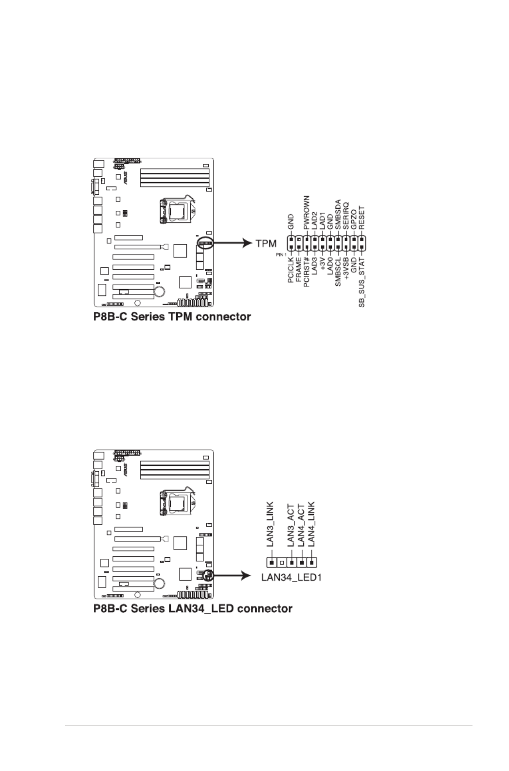
11. TPM connector (20-1 pin TPM)
This connector supports a Trusted Platform Module (TPM) system, which can
securely store keys, digital certicates, passwords, and data. A TPM system
also helps enhance network security, protects digital identities, and ensures
platform integrity.
12. LAN34 LED connector
(5-1 pin LAN34_LED1,,
P8B-C/4L, P8B-C/SAS/4L only
)
This connector supports a backplane with 4 LAN LEDs. Connect the LAN
LED cable to the backplane for LAN activity indication.
2-40 Chapter 2: Hardware information
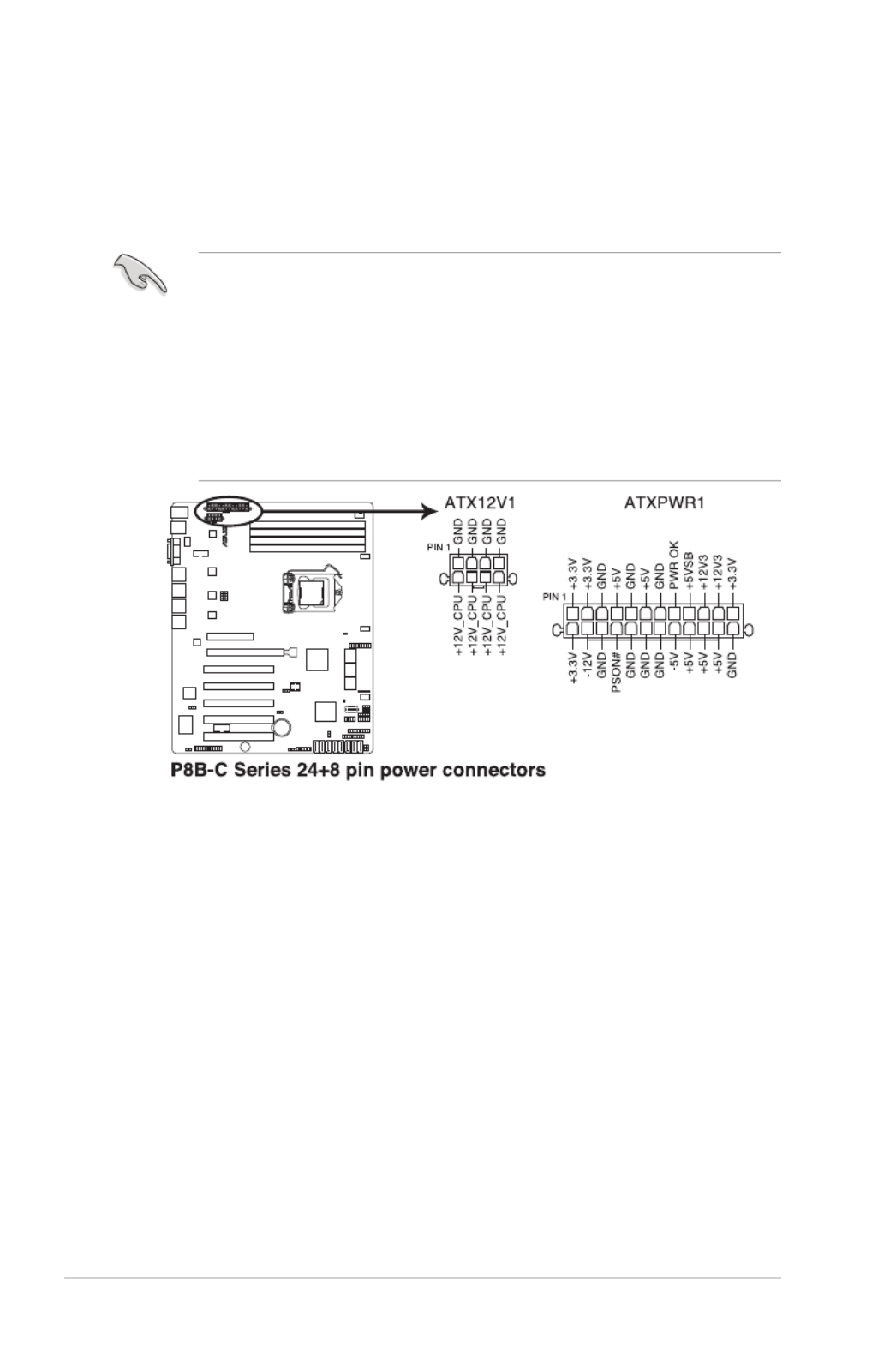
13. ATX power connectors (24-pin ATXPWR1, 8-pin ATX12V1)
These connectors are for an ATX power supply plugs. The power supply
plugs are designed to t these connectors in only one orientation. Find the
proper orientation and push down rmly until the connectors completely t.
• DO NOT forget to connect the 24+8-pin power plugs; otherwise, the system
will not boot up.
• Use of a PSU with a higher power output is recommended when conguring
a system with more power-consuming devices. The system may become
unstable or may not boot up if the power is inadequate.
• This motherboard supports ATX2.0 PSU or later version.
• Ensure that your power supply unit (PSU) can provide at least the minimum
power required by your system.

ASUS P8B-C series 2-41
14. System panel connector (20-1 pin PANEL1)
This connector supports several chassis-mounted functions.
1. System power LED (3-pin PLED)
This 3-pin connector is for the system power LED. Connect the chassis
power LED cable to this connector. The system power LED lights up
when you turn on the system power, and blinks when the system is in
sleep mode.
2. Message LED (2-pin MLED)
This 2-pin connector is for the message LED cable that connects to
the front message LED. The message LED is controlled by Hardware
monitor to indicate an abnormal event occurance.
3. System warning speaker (4-pin SPEAKER)
This 4-pin connector is for the chassis-mounted system warning
speaker. The speaker allows you to hear system beeps and warnings.
4. Hard disk drive activity LED (2-pin HDDLED)
This 2-pin connector is for the HDD Activity LED. Connect the HDD
Activity LED cable to this connector. The HDD LED lights up or ashes
when data is read from or written to the HDD.
5. Power button/soft-off button (2-pin PWRSW)
This connector is for the system power button. Pressing the power
button turns the system on or puts the system in sleep or soft-off mode
depending on the BIOS settings. Pressing the power switch for more
than four seconds while the system is ON turns the system OFF.
6. Reset button (2-pin RESET)
This 2-pin connector is for the chassis-mounted reset button for system
reboot without turning off the system power.

ASUS P8B-C series 2-43
1. Front panel SMB (6-1 pin FPSMB)
These leads connect the front panel SMBus cable.
2. LAN activity LED (2-pin LAN1_LED, LAN2_LED)
These leads are for Gigabit LAN activity LEDs on the front panel.
3. Chassis intrusion (4-1 pin CHASSIS)
These leads are for the intrusion detection feature for chassis with
intrusion sensor or microswitch. When you remove any chassis
component, the sensor triggers and sends a high-level signal to these
leads to record a chassis intrusion event. The default setting is short
CASEOPEN and GND pin by jumper cap to disable the function.
4. Locator LED (2-pin LOCATORLED1 and 2-pin LOCATORLED2)
These leads are for the locator LED1 and LED2 on the front panel.
Connect the Locator LED cables to these 2-pin connector. The LEDs will
light up when the Locator button is pressed.
5. Locator Button/Swich (2-pin LOCATORBTN)
These leads are for the locator button on the front panel. This button
queries the state of the system locator.

3
Chapter 3: Powering up
This chapter describes the power up
sequence, and ways of shutting down the
system.

ASUS P8B-C series
Chapter summary
3
3.1 Starting up for the rst time ........................................................ 3-3
3.2 Powering off the computer .......................................................... 3-4

3-4 Chapter 3: Powering up
3.2 Powering off the computer
3.2.1 Using the OS shut down function
If you are using Windows ® 2008 Server:
1. Click the Start button, move the cursor to the triangle on the right of Log off ,
and then click Shut Down .
2. From the Shutdown Event Tracker , select the option that best describes
why you want to shut down the computer.
3. Ensure that the Planned check box is checked.
4. If necessary, key in comments.
5. Click OK.
3.2.2 Using the dual function power switch
While the system is ON, pressing the power switch for less than four seconds puts
the system to sleep mode or to soft-off mode, depending on the BIOS setting.
Pressing the power switch for more than four seconds lets the system enter the
soft-off mode regardless of the BIOS setting.

4
Chapter 4: BIOS setup
This chapter tells how to change the
system settings through the BIOS Setup
menus. Detailed descriptions of the BIOS
parameters are also provided.

Chapter summary
4
ASUS P8B-C series
4.1 Managing and updating your BIOS ............................................ 4-3
4.2 BIOS setup program .................................................................... 4-7
4.3 Main menu .................................................................................. 4-10
4.4 Event Logs menu ....................................................................... 4-12
4.5 Advanced menu ......................................................................... 4-14
4.6 Monitor menu ............................................................................. 4-26
4.7 Boot menu .................................................................................. 4-27
4.8 Tool menu ................................................................................... 4-29
4.9 Exit menu .................................................................................... 4-29

ASUS P8B-C series 4-3
4.1 Managing and updating your BIOS
The following utilities allow you to manage and update the motherboard Basic
Input/Output System (BIOS) setup:
1. ASUS CrashFree BIOS 3 (To recover the BIOS using a bootable USB ash
disk drive when the BIOS le fails or gets corrupted.)
2. ASUS EZ Flash 2 (Updates the BIOS using a USB ash disk.)
3. BUPDATER utility (Updates the BIOS in DOS mode using a bootable USB
ash disk drive.)
Refer to the corresponding sections for details on these utilities.
Save a copy of the original motherboard BIOS le to a bootable USB ash
disk drive in case you need to restore the BIOS in the future. Copy the original
motherboard BIOS using the BUPDATER utility.
4.1.1 ASUS CrashFree BIOS 3 utility
The ASUS CrashFree BIOS 3 is an auto recovery tool that allows you to restore
the BIOS le when it fails or gets corrupted during the updating process. You can
update a corrupted BIOS le using a USB ash drive that contains the updated
BIOS le.
Prepare a USB ash drive containing the updated motherboard BIOS before
using this utility.
To recover the BIOS from a USB ash drive:
1. Insert the USB ash drive with the original or updated BIOS le to one USB
port on the system.
2. The utility will automatically recover the BIOS. It resets the system when the
BIOS recovery nished.
DO NOT shut down or reset the system while recovering the BIOS! Doing so
would cause system boot failure!
The recovered BIOS may not be the latest BIOS version for this motherboard.
Visit the ASUS website at www.asus.com to download the latest BIOS le.
Produkt Specifikationer
| Mærke: | Asus |
| Kategori: | Server |
| Model: | P8B-C/4L |
Har du brug for hjælp?
Hvis du har brug for hjælp til Asus P8B-C/4L stil et spørgsmål nedenfor, og andre brugere vil svare dig
Server Asus Manualer

9 December 2024
6 Oktober 2024
21 September 2024
1 September 2024
30 August 2024
27 August 2024
27 August 2024
20 August 2024
19 August 2024
8 August 2024
Server Manualer
- Server QNAP
- Server Bosch
- Server Acer
- Server Sony
- Server HP
- Server D-Link
- Server Gigabyte
- Server Toshiba
- Server Lenovo
- Server Abus
- Server Planet
- Server Black Box
- Server TRENDnet
- Server Buffalo
- Server Medion
- Server Linksys
- Server Megasat
- Server Cisco
- Server Seagate
- Server Netgear
- Server Tripp Lite
- Server Western Digital
- Server Technics
- Server Digitus
- Server Dell
- Server Fujitsu
- Server MSI
- Server NEC
- Server APC
- Server LevelOne
- Server FLIR
- Server ZyXEL
- Server Eaton
- Server ELAC
- Server Synology
- Server Hikvision
- Server Monacor
- Server AVerMedia
- Server Asustor
- Server Kramer
- Server Hanwha
- Server LaCie
- Server Naim
- Server Fantec
- Server Provision-ISR
- Server Quantum
- Server Axis
- Server ACTi
- Server Digi
- Server ATen
- Server Teo
- Server Vimar
- Server Smart-AVI
- Server Intel
- Server Supermicro
- Server StarTech.com
- Server Conceptronic
- Server Rocstor
- Server IStarUSA
- Server Blackmagic Design
- Server Lindy
- Server Veritas
- Server Promise Technology
- Server Sitecom
- Server HGST
- Server AMX
- Server Intellinet
- Server Iomega
- Server Silverstone
- Server Geovision
- Server Ernitec
- Server KanexPro
- Server Gefen
- Server Moxa
- Server C2G
- Server Allnet
- Server Maxdata
- Server Matrox
- Server Valcom
- Server Freecom
- Server IoSafe
- Server Revox
- Server Luxman
- Server G-Technology
- Server Areca
- Server SEH
- Server Ibm
- Server Sonnet
- Server TAIDEN
- Server SIIG
- Server Advantech
- Server Mobotix
- Server Extron
- Server Avocent
- Server Silex
- Server Middle Atlantic
- Server In Win
- Server Sun
- Server Atlona
- Server MvixUSA
- Server Dual Bay
- Server Raidsonic
- Server EMC
- Server Infortrend
- Server Opengear
- Server EXSYS
- Server Raritan
- Server Chenbro Micom
- Server Mr. Signal
- Server Atlantis Land
- Server Lantronix
- Server NETSCOUT
- Server Origin Storage
- Server IMC Networks
Nyeste Server Manualer

9 Marts 2025
9 Marts 2025
9 Marts 2025

30 Januar 2025
30 Januar 2025
23 Januar 2025
23 Januar 2025
23 Januar 2025
23 Januar 2025
23 Januar 2025