Asus ROG STRIX Z790-I GAMING WIFI Manual
Asus
Stikkontakt
ROG STRIX Z790-I GAMING WIFI
Læs nedenfor 📖 manual på dansk for Asus ROG STRIX Z790-I GAMING WIFI (78 sider) i kategorien Stikkontakt. Denne guide var nyttig for 14 personer og blev bedømt med 4.5 stjerner i gennemsnit af 2 brugere
Side 1/78

Motherboard
ROG STRIX
Z790-I
GAMING
WIFI

Copyright © 2022 ASUSTeK COMPUTER INC. All Rights Reserved.

Contents
Safety information v .......................................................................................................
About this guide vi .........................................................................................................
ROG STRIX Z790-I GAMING WIFI specifications summary vii ...................................
Package contents xii ......................................................................................................
Chapter 1: Product Introduction
1.1 Before you proceed 1-1 ...................................................................................
1.2 Motherboard layout 1-2 ....................................................................................
Chapter 2: Basic Installation
2.1 Building your PC system 2-1 ...........................................................................
2.2 ROG STRIX HIVE 2-20 ......................................................................................
2.3 BIOS update utility 2-22 ...................................................................................
2.4 EZ Mode AI OC 2-24 .........................................................................................
2.5 Clear CMOS button 2-25 ..................................................................................
2.6 Motherboard rear and audio connections 2-26 .............................................
2.7 Starting up for the first time 2-27 ....................................................................
2.8 Turning off the computer 2-27 ........................................................................
Chapter 3: BIOS and RAID Support
3.1 Knowing BIOS 3-1 ............................................................................................
3.2 BIOS setup program 3-2 ..................................................................................
3.3 ASUS EZ Flash 3 3-3 ........................................................................................
3.4 ASUS CrashFree BIOS 3 3-4 ............................................................................
3.5 RAID configurations 3-5 ..................................................................................

Appendix
Notices A-1 ....................................................................................................................
Warranty A-11 .................................................................................................................
ASUS contact information A-13 ....................................................................................
Service and Support A-13 .............................................................................................

Safety information
Electrical safety
Operation safety
Button/Coin Batteries Safety Information
WARNING
KEEP OUT OF REACH OF CHILDREN

ROG STRIX Z790-I GAMING WIFI specifications summary
CPU
* Refer to www.asus.com for CPU support list.
** Intel®
Turbo Boost Max Technology 3.0 support depends on the CPU types.
Chipset
Memory
* Supported memory types, data rate (speed), and number of DRAM modules
may vary depending on the CPU types and memory configuration, for more
information refer to www.asus.com for the memory support list.
Graphics * Graphics specifications may vary between CPU types. Please refer to
www.intel.com for any updates.
** Support 4K@60Hz as specified in HDMI®
2.1.
*** VGA resolution support depends on processors’ or graphic cards’
resolution.
Expansion Slots
Intel® 13
th & 12th Gen Processors*
* Please check the PCIe bifurcation table on the support site
(https://www.asus.com/support/FAQ/1037507/).
Storage
Total supports 2 x M.2 slots and 2 x SATA 6Gb/s ports
Intel® 13
th & 12th Gen Processors
* M.2_1 comes from Intel®
Z790 Chipset when PCIe Gen5 expansion slot
is switched to p7-x16 mode. This can be configured in the BIOS under the
Advanced > Onboard Devices Configuration menu.
** Install ROG FPS-II Card to support 2 x SATA 6Gb/s ports.
Ethernet

ROG STRIX Z790-I GAMING WIFI specifications summary
Wireless & Bluetooth®
* WiFi 6E 6GHz regulatory may vary between countries.
** The Bluetooth® version may vary, please refer to the Wi-Fi module
manufacturer’s website for the latest specifications.
USB
Rear USB (Total 9 ports)
Front USB (Total 3 ports)
ROG STRIX HIVE (Total 2 ports)
ROG FPS-II C (Total 3 ports)
Audio
ROG High Definition Audio CODEC ALC4050
Audio Features
* All audio functions on ROG STRIX Z790-I GAMING WIFI are supported
through the ROG STRIX HIVE.
Back Panel I/O Ports

ROG STRIX Z790-I GAMING WIFI specifications summary
Special Features
Aura Sync
ROG STRIX HIVE
®
Software Features
ROG Exclusive Software
ASUS Exclusive Software
ROG STRIX Z790-I GAMING WIFI specifications summary
Software Features
UEFI BIOS
BIOS
Manageability
Operating System
Form Factor

Package contents
Chapter 1
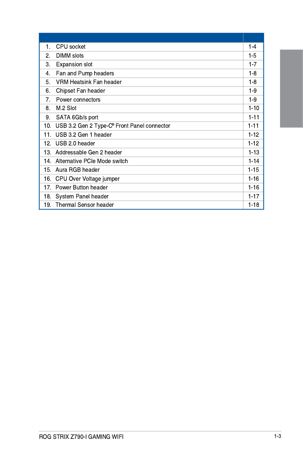
Layout contents Page

Chapter 1
1. CPU socket

Chapter 1
2. DIMM slots
Recommended memory configurations
Chapter 1
Memory configurations

Chapter 1
3. Expansion slots
Chapter 1
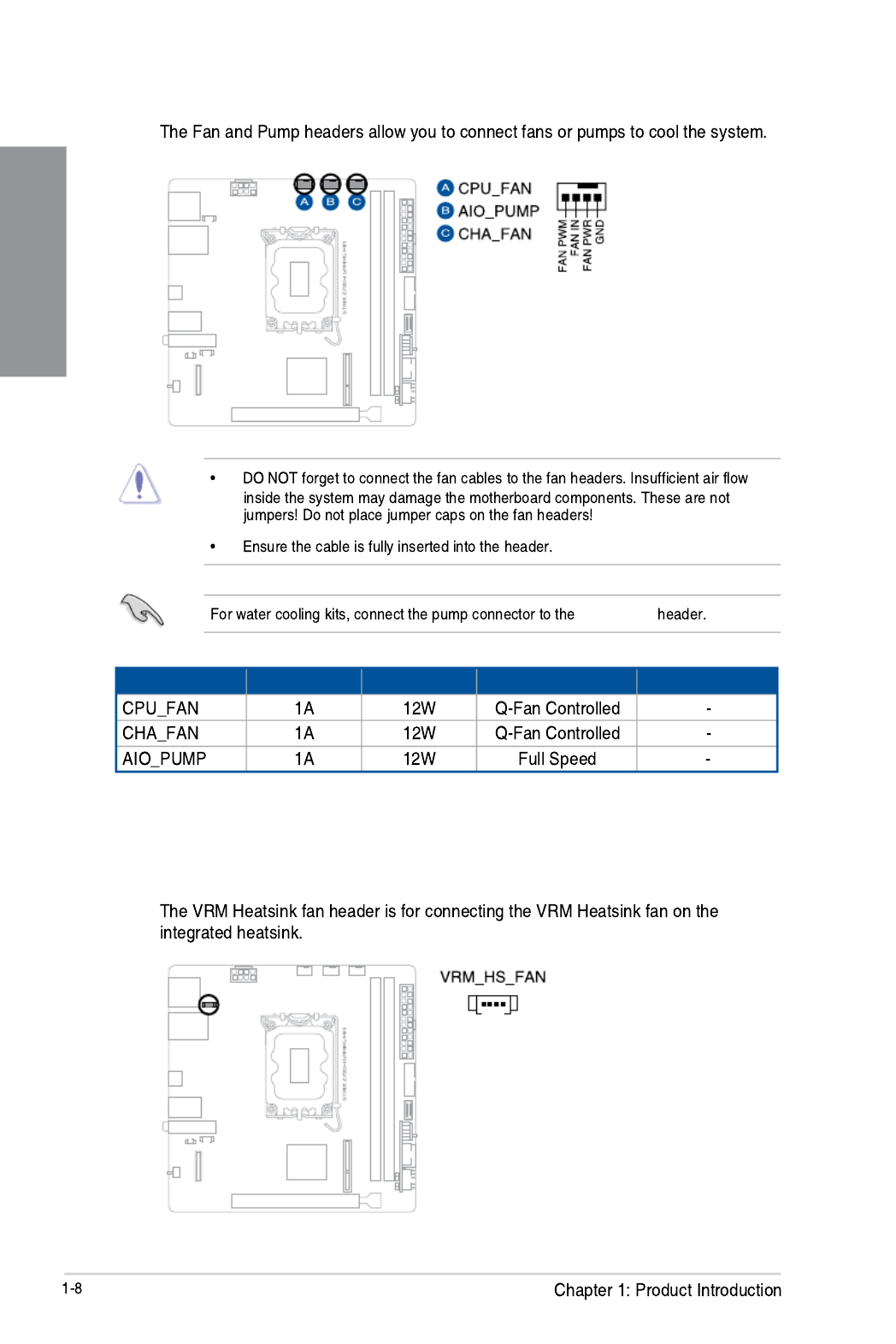
4. Fan and Pump headers
AIO_PUMP
Header Max. Current Max. Power Default Speed Shared Control
5. VRM Heatsink fan header
Chapter 1
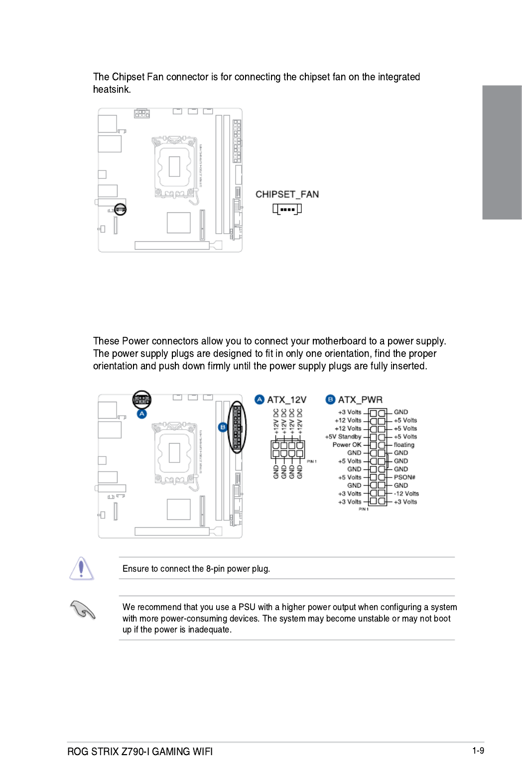
6. Chipset Fan connector
7. Power connectors

Chapter 1
8. M.2 slot
Intel® 13th & 12th Gen Processors:
Intel® Z790 Chipset*:
* M.2_1 comes from Intel® Z790 Chipset when PCIe Gen5 expansion slot is switched to
x16 mode. This can be configured in the BIOS under the Advanced > Onboard Devices
Configuration menu.
[Auto mode]
[X16 mode]

Chapter 1
9. SATA 6Gb/s port
SATA6G_1-2
RAID Configuration Guide
RAID Configuration Guide
10. USB 3.2 Gen 2x2 Type-C® Front Panel connector

Chapter 1
11. USB 3.2 Gen 1 header
12. USB 2.0 header
USB13

Chapter 1
13. Addressable Gen2 header

Chapter 1
14. Alternative PCIe Mode switch
Auto
1
st step
2
nd step

Chapter 1
15. AURA RGB header
Chapter 1
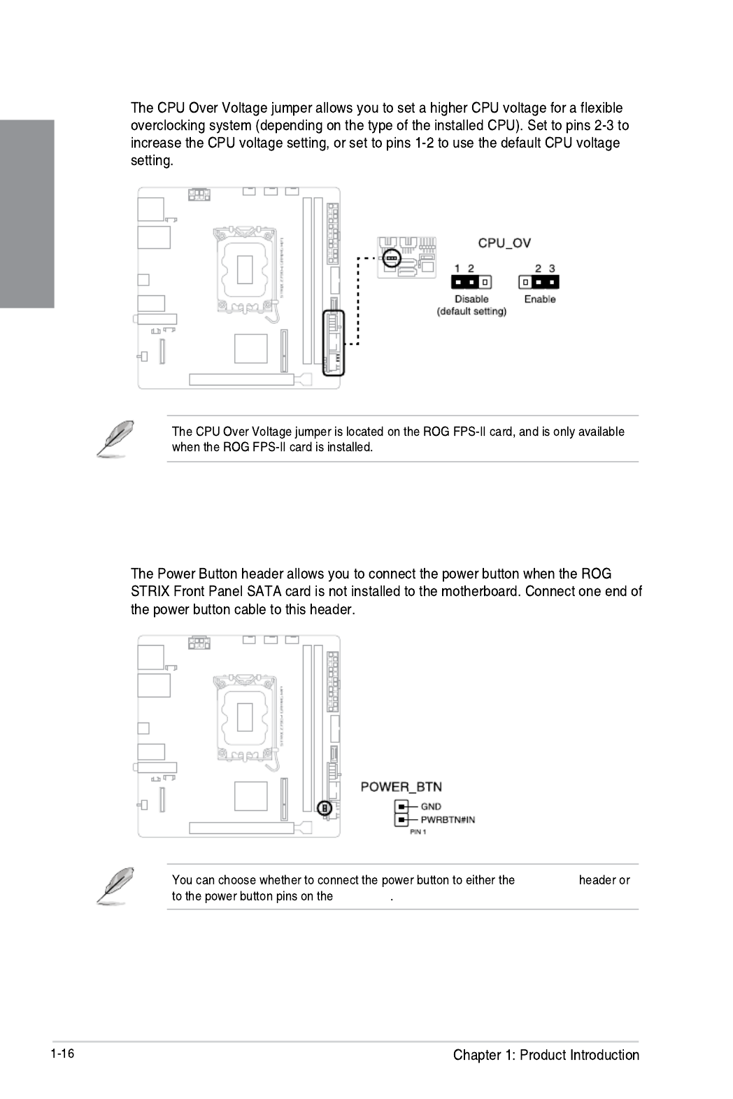
17. Power Button header
PWR_BTN
F_PANEL
16. CPU Over Voltage jumper
Chapter 1
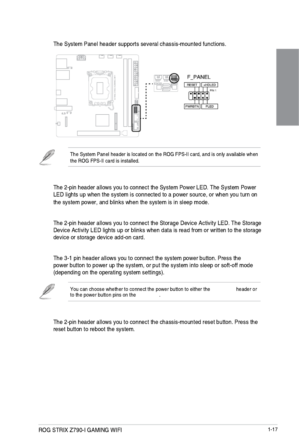
18. System Panel header
• System Power LED header (PLED)
• Storage Device Activity LED header (HDLED)
• Power Button/Soft-off Button header (PWRBTN)
PWR_BTN
F_PANEL
• Reset button header (RESET)

Chapter 1
19. Thermal Sensor header
T_SENSOR2

ROG STRIX Z790-I GAMING WIFI 2-1
2
Basic Installation
2.1 Building your PC system
The diagrams in this section are for reference only. The motherboard layout may vary with
models, but the installation steps are the same for all models.
Chapter 2: Basic Installation
2.1.1 CPU installation
• Ensure that you install the correct CPU designed for LGA1700 socket only. DO NOT
install a CPU designed for LGA1155, LGA1156, LGA1151, and LGA1200 sockets on
the LGA1700 socket.
• ASUS will not cover damages resulting from incorrect CPU installation/removal,
incorrect CPU orientation/placement, or other damages resulting from negligence by
the user.
Take caution when lifting the load
lever, ensure to hold onto the load
lever when releasing the load
lever. Letting go of the load lever
immediately after releasing it may
cause the load lever to spring
back and cause damage to your
motherboard.

ROG STRIX Z790-I GAMING WIFI 2-3
Chapter 2
2.1.2 Cooling system installation
To install a CPU heatsink and fan assembly
• Apply Thermal Interface Material to
the CPU cooling system and CPU
before you install the cooling system,
if necessary.
• Ensure to remove the CPU Socket
lever protector on the lever latch
before installing the cooling system,
failure to do so may cause damages
to your system.

2-4 Chapter 2: Basic Installation
Chapter 2
LGA1200
LGA1700
• We recommend using a
LGA1700 compatible cooling
system on an Intel ® 700 series
motherboard.
• Additional holes for LGA1200
compatible cooling systems
are also available on ASUS’
Intel® 700 series motherboards,
however, we still strongly advise
consulting with your cooling
system vendor or manufacturer
on the compatibility and
functionality of the cooling
system.
• Push-pin type LGA1200
compatible cooling systems
cannot be installed to this
motherboard.

ROG STRIX Z790-I GAMING WIFI 2-5
Chapter 2
To install an AIO cooler
AIO_PUMP
CHA_FANP
CPU_FAN
• We recommend using a LGA1700 compatible cooling system on an Intel ® 700 series
motherboard.
• Additional holes for LGA1200 compatible cooling systems are also available on
ASUS’ Intel ® 700 series motherboards, however, we still strongly advise consulting
with your cooling system vendor or manufacturer on the compatibility and
functionality of the cooling system.
• If you wish to install an AIO cooler, we recommend installing the AIO cooler after
installing the motherboard into the chassis.

2-6 Chapter 2: Basic Installation
Chapter 2
2.1.3 DIMM installation
To remove a DIMM
ROG STRIX Z790-I GAMING WIFI 2-7
Chapter 2
2.1.4 M.2 installation
Supported M.2 type varies per motherboard.
If the thermal pad on the M.2 heatsink becomes damaged, we recommend replacing it
with the bundled thermal pad or a thermal pad with a thickness of 1.25mm.
• Use a Phillips screwdriver when removing or installing the screws or screw stands
mentioned in this section.
• The M.2 is purchased separately.
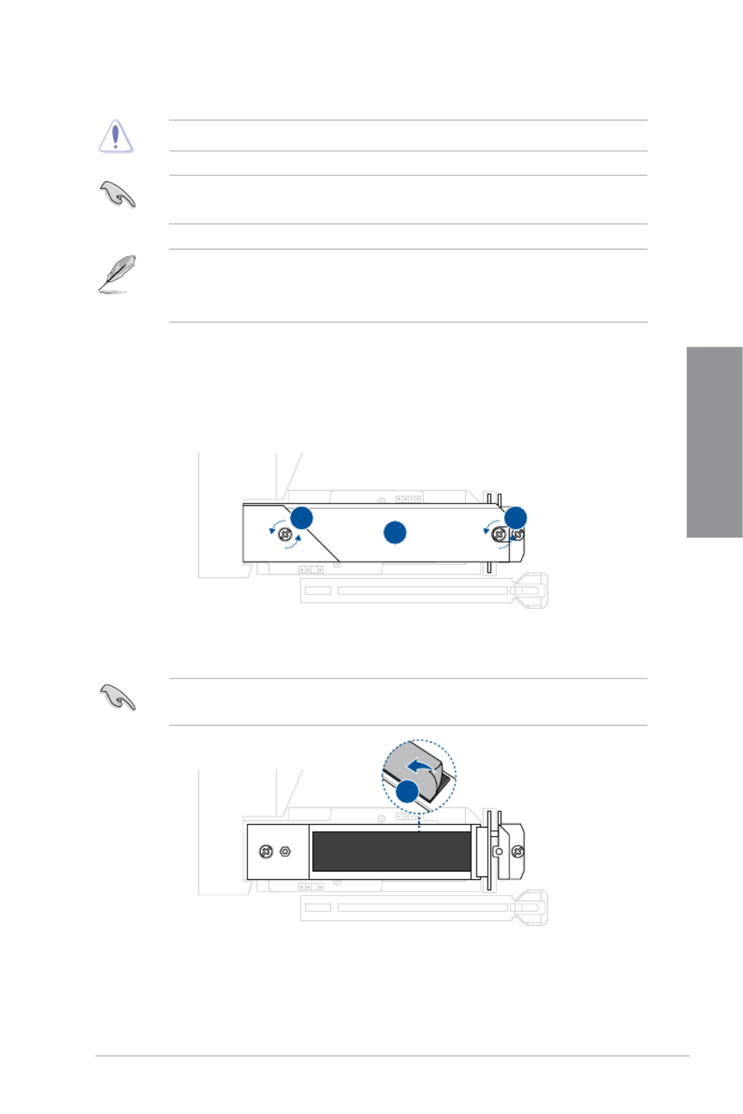
1. Loosen the screws from the top M.2 heatsink.
2. Lift and remove the top heatsink.
To install an M.2 to M.2_1(SOCKET3) slot
3. Remove the plastic film from the thermal pad on the bottom heatsink.
If the thermal pad on the M.2 heatsink becomes damaged, we recommend replacing it
with the bundled thermal pad or a thermal pad with a thickness of 1.25mm.
2
1 1
3

2-8 Chapter 2: Basic Installation
Chapter 2
4. Install your M.2 to the M.2 slot with the bottom of the M.2 facing upwards.
5
6
7 7
5. (optional) Remove the plastic film from the thermal pad on the bottom of the top
heatsink.
• Follow this step only when you install a double-sided M.2 storage device.
• If the thermal pad on the M.2 heatsink becomes damaged and needs to replaced, we
recommend replacing it with a thermal pad with a thickness of 1.25mm.
6. Push the M.2 down and replace the top heatsink.
7. Secure the top heatsink and M.2 using the two (2) screws.
4

ROG STRIX Z790-I GAMING WIFI 2-9
Chapter 2
1. Loosen the screws from the top M.2 heatsink.
2. Lift and remove the top heatsink.
3. Remove the two (2) screws securing the M.2_1(SOCKET3) bottom heatsink.
4. Lift and remove the M.2_1(SOCKET3) bottom heatsink.
To install an M.2 to M.2_2(Socket3) slot
2
1 1
4
33
5. Install your M.2 to your M.2 slot. The steps may differ between installing M.2 of
different lengths, please refer to the different types and their installation steps below:

2-10
Chapter 2
For 2280 length
A. (optional) Install the bundled rubber for M.2 if you are installing a single sided
M.2 storage device. DO NOT install the bundled rubber for M.2 when installing
a double-sided M.2 storage device. The rubber installed by default is compatible
with double sided M.2 storage devices.
B. Rotate and adjust the M.2 Q-latch so that the handle points away from the M.2
slot.
C. Install your M.2 to the M.2 slot.
D. Rotate the M.2 Q-Latch clockwise to secure the M.2 in place.
Bundled rubber for M.2
Produkt Specifikationer
| Mærke: | Asus |
| Kategori: | Stikkontakt |
| Model: | ROG STRIX Z790-I GAMING WIFI |
Har du brug for hjælp?
Hvis du har brug for hjælp til Asus ROG STRIX Z790-I GAMING WIFI stil et spørgsmål nedenfor, og andre brugere vil svare dig
Stikkontakt Asus Manualer

10 Januar 2025
19 December 2024
19 December 2024
19 December 2024
1 September 2024
1 September 2024
1 September 2024
1 September 2024
1 September 2024
1 September 2024
Stikkontakt Manualer
- Stikkontakt Ikea
- Stikkontakt Denver
- Stikkontakt CyberPower
- Stikkontakt Hager
- Stikkontakt Silverline
- Stikkontakt Philips
- Stikkontakt Emos
- Stikkontakt Gigabyte
- Stikkontakt Biltema
- Stikkontakt AVM
- Stikkontakt Hama
- Stikkontakt Smartwares
- Stikkontakt Busch-Jaeger
- Stikkontakt Trotec
- Stikkontakt Vivanco
- Stikkontakt Osram
- Stikkontakt Gembird
- Stikkontakt Bose
- Stikkontakt Powerfix
- Stikkontakt Tripp Lite
- Stikkontakt Reer
- Stikkontakt Craftsman
- Stikkontakt Digitus
- Stikkontakt Gamma
- Stikkontakt Niceboy
- Stikkontakt Peerless-AV
- Stikkontakt Schneider
- Stikkontakt Bachmann
- Stikkontakt APC
- Stikkontakt Kathrein
- Stikkontakt Perel
- Stikkontakt JUNG
- Stikkontakt ORNO
- Stikkontakt ECS
- Stikkontakt Brennenstuhl
- Stikkontakt Hazet
- Stikkontakt Manhattan
- Stikkontakt SPC
- Stikkontakt LogiLink
- Stikkontakt Easy Home
- Stikkontakt Kramer
- Stikkontakt Lanberg
- Stikkontakt Anslut
- Stikkontakt Fibaro
- Stikkontakt Panduit
- Stikkontakt Eurolite
- Stikkontakt Vimar
- Stikkontakt Lenoxx
- Stikkontakt InLine
- Stikkontakt Crestron
- Stikkontakt Showtec
- Stikkontakt Kogan
- Stikkontakt Delta
- Stikkontakt Elektrobock
- Stikkontakt Konig & Meyer
- Stikkontakt Neutrik
- Stikkontakt Biostar
- Stikkontakt Homematic IP
- Stikkontakt V-TAC
- Stikkontakt Legrand
- Stikkontakt Schwaiger
- Stikkontakt Heitronic
- Stikkontakt Savio
- Stikkontakt PCE
- Stikkontakt Bearware
- Stikkontakt Workzone
- Stikkontakt KlikaanKlikuit
- Stikkontakt Metz
- Stikkontakt AS - Schwabe
- Stikkontakt Duro
- Stikkontakt Gira
- Stikkontakt Peerless
- Stikkontakt Monoprice
- Stikkontakt Berker
- Stikkontakt Extron
- Stikkontakt Leviton
- Stikkontakt Ebode
- Stikkontakt InterBar
- Stikkontakt Pancontrol
- Stikkontakt Phoenix Contact
- Stikkontakt Metz Connect
- Stikkontakt DEHN
- Stikkontakt Omnilux
- Stikkontakt Atlona
- Stikkontakt Hoopzi
- Stikkontakt Hall Research
- Stikkontakt Crydom
- Stikkontakt Adam Hall
- Stikkontakt 360 Electrical
- Stikkontakt PS Audio
- Stikkontakt IOIO
Nyeste Stikkontakt Manualer

12 Januar 2025
10 Januar 2025
3 Januar 2025
30 December 2025
29 December 2024
29 December 2024
29 December 2024
29 December 2024
29 December 2024
29 December 2024