Asus Sabertooth Z97 MARK1 Manual
Læs nedenfor 📖 manual på dansk for Asus Sabertooth Z97 MARK1 (174 sider) i kategorien Bundkort. Denne guide var nyttig for 6 personer og blev bedømt med 4.5 stjerner i gennemsnit af 2 brugere
Side 1/174

Motherboard
SABERTOOTH Z97
MARK 1

Copyright 2014 ASUSTeK COMPUTER INC. All Rights Reserved.
Offer to Provide Source Code of Certain Software
gpl@asus.com

Contents
Safety information vi ......................................................................................................
About this guide vii ........................................................................................................
SABERTOOTH Z97 MARK 1 specifications summary ix ............................................
Package contents xiii .....................................................................................................
Installation tools and components xiv .........................................................................
Chapter 1: Product Introduction
1.1 Special features.......................................................................................... 1-1
1.2 Motherboard overview 1-7 ...............................................................................
Chapter 2: Basic installation
2.1 Building your PC system 2-1 ...........................................................................
2.2 BIOS update utility 2-11 ...................................................................................
2.3 Motherboard rear and audio connections 2-12 .............................................
2.4 Starting up for the first time 2-16 ....................................................................
2.5 Turning off the computer 2-16 ........................................................................

Chapter 3: BIOS setup
3.1 Knowing BIOS 3-1 ............................................................................................
3.2 BIOS setup program 3-2 ..................................................................................
3.3 My Favorites 3-10 .............................................................................................
3.4 Main menu 3-12 ................................................................................................
3.5 Ai Tweaker menu 3-14 ......................................................................................
3.6 Advanced menu 3-30 .......................................................................................
3.7 Monitor menu 3-46 ...........................................................................................
3.8 Boot menu 3-51 ................................................................................................
3.9 Tool menu 3-57 .................................................................................................
3.10 Exit menu 3-60 ..................................................................................................
3.11 Updating BIOS 3-61 ..........................................................................................
Chapter 4: Software support
4.1 Installing an operating system 4-1 .................................................................
4.2 Support DVD information 4-1 ..........................................................................
4.3 Software information 4-4 .................................................................................
4.4 AI Suite 3 4-4 .....................................................................................................
4.5 Turbo LAN 4-24 .................................................................................................
4.6 Audio configurations 4-25 ...............................................................................
Chapter 5: RAID support
5.1 RAID configurations 5-1 ..................................................................................
5.2 Installing the RAID driver during Windows
® OS ................................................
installation 5-7 ................................................................................................................
Appendices
Notices A-1 ....................................................................................................................
ASUS contact information A-5 ......................................................................................
Safety information
Electrical safety
Operation safety

About this guide
How this guide is organized
• Chapter 1: Product introduction
• Chapter 2: Basic installation
• Chapter 3: BIOS setup
• Chapter 4: Software support
• Chapter 5: RAID support
Where to find more information
1. ASUS websites
2. Optional documentation

Conventions used in this guide
DANGER/WARNING:
CAUTION:
IMPORTANT:
NOTE:
Typography
Bold text

SABERTOOTH Z97 MARK 1 specifications summary
CPU
* The Intel ® Turbo Boost Technology 2.0 support depends on the CPU
types.
* Refer to www.asus.com for the complete CPU support list.
Chipset
Memory
* Hyper DIMM support is subject to the physical characteristics of
individual CPUs. Please refer to Memory QVL (Qualified Vendors List)
for details.
* Refer to www.asus.com or this user guide for the complete the Memory
QVL (Qualified Vendors List).
Expansion slots
* The PCIe 2.0 p9-x16 slot shares bandwidth with PCIe 2.0 x1_3 slot and
USB3 E1/2 ports at back. The PCIe 2.0 p9-x16 slot default setting is in p9-x1
mode.
VGA
* DisplayPort 1.2 Multi-Stream Transport compliant. Supports up to three
displays of DisplayPort 1.2 monitors on a daisy chain.
Multi-GPU support
LAN

Storage
Intel® Z97 Express Chipset with RAID 0, 1, 5, 10 and Intel
®
Rapid Start Technology 13 support
1 x ASMedia® SATA 6Gb/s controller**
* These functions will work depending on the CPU installed.
** These SATA ports are for data hard drives only. ATAPI devices are not
supported.
Audio
USB
Intel® Z97 Express Chipset - supports ASUS USB 3.0 Boost
ASMedia® USB 3.0 controller - supports ASUS USB 3.0 Boost
Exclusive TUF Features
“Ultimate COOL!” Thermal Solution
“We Got Your Back” Shape Force
“TUF ENGINE” Power Design
“SAFE & Stable!” Guardian Angel
SABERTOOTH Z97 MARK 1 specifications summary

SABERTOOTH Z97 MARK 1 specifications summary
Other Special Features
Rear Panel I/O Ports
Internal I/O connectors
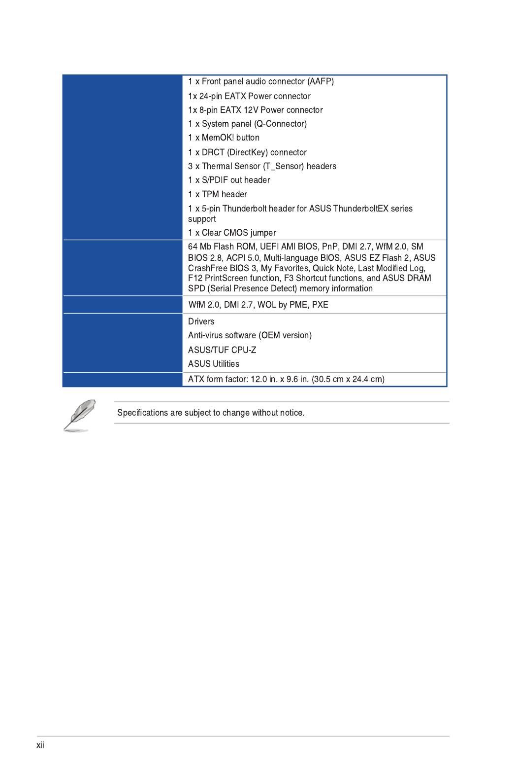
Internal I/O connectors
BIOS features
Manageability
Support DVD contents
Form factor
SABERTOOTH Z97 MARK 1 specifications summary

User Manual
ASUS SABERTOOTH Z97 MARK 1
motherboard
Technical documentations,
certification and warranty card Support DVD
4 x Serial ATA 6.0 Gb/s cables 1 x ASUS SLI™ bridge connector
(7 cm) 1 x ASUS Q-Shield
1 x 2-in-1 ASUS Q-Connector kit 1 x 35 mm Assistant fan
1 x 40 mm Assistant fan
2 x short fan screws
4 x long fan screws
3 x PCIe p13-x16 slot covers
3 x PCIe p13-x1 slot covers 2 x DRAM slot covers Rear I/O dust filter
TUF Accessory Installation Guide
1 x Connector cap set
(LAN cap, HDMI cap, DVI cap, DP
cap, Front USB 3.0 cap)
3 x Thermistor cables
SATA
Exp ress
7 x SATA connector caps
1 x SATA Expresss connector cap
8 x Back I/O USB 3.0/2.0 connector
caps
2 x Onboard USB 2.0 connector
caps 5 x Audio connector caps
Package contents

Installation tools and components
1 bag of screws Philips (cross) screwdriver
PC chassis Power supply unit
Intel ®
LGA1150 CPU Intel
® LGA1150 compatible CPU Fan
DIMM SATA hard disk drive
SATA optical disc drive (optional) Graphics card (optional)

Chapter 1
Product introduction
1.1 Special features
1.1.1 Product highlights
LGA1150 socket for the 4th, New 4th, and 5th generation Intel
® Core™ i7 /
Intel® Core™ i5 / Intel® Core™ i3, Pentium®, and Celeron® processors
Intel® Z97 Express Chipset
PCI Express®
3.0
Dual-Channel DDR3 1866 / 1600 / 1333 MHz Support
Quad-GPU SLI and Quad GPU CrossFireX™ Support
SATA Express support
Chapter 1: Product Introduction
Chapter 1
Intel® Smart Response Technology
* 4th Generation Intel® Core™ processors family support Intel®
Smart Response Technology.
** An operating system must be installed on the HDD to launch Intel
®
Smart Response Technology.
*** The SSD is reserved for caching function.
Intel® Smart Connect Technology
Intel® Rapid Start Technology
Complete USB 3.0 integration
Extra SATA 6.0 Gb/s Support
1.1.2 “Ultimate COOL” Thermal Solutions
Thermal Armor with flow valve
Thermal Radar 2

Chapter 1
1.1.3 “TUF Engine” Power Design
Digital Power Control
TUF Components (New Alloy Choke, 10K Ti-Cap. & MOSFET; certified by
military-standard)
1.1.4 “Safe & Stable!” Guardian Angel
TUF Fortifier
Dust Defenders
TUF ESD Guards
MemOK!

Chapter 1
1.1.5 ASUS EZ DIY
ASUS UEFI BIOS (EZ Mode)
ASUS Q-Design
ASUS Q-shield
ASUS Q-connector
Chapter 1
1.1.6 ASUS Exclusive Features
Remote GO!
• Cloud GO!:
ASUS Media Streamer
Remote Desktop
File Transfer
USB 3.0 Boost
USB Charger+
USB BIOS Flashback
AI Suite 3

Chapter 1
1.1.7 Other special features
DisplayPort Support
HDMI Support
ErP Ready

Chapter 1
1.2 Motherboard overview
1.2.1 Before you proceed

Chapter 1
1.2.9 Internal connectors 2.3.1 Rear I/O connection
1.2.2 Motherboard layout

Chapter 1
Layout contents
Connectors/Jumpers/Slots Page

Chapter 1
1.2.3 Central Processing Unit (CPU)

Chapter 1
Recommended memory configurations
1.2.4 System memory

Chapter 1
Ai Tweaker menu
Memory configurations

Chapter 1
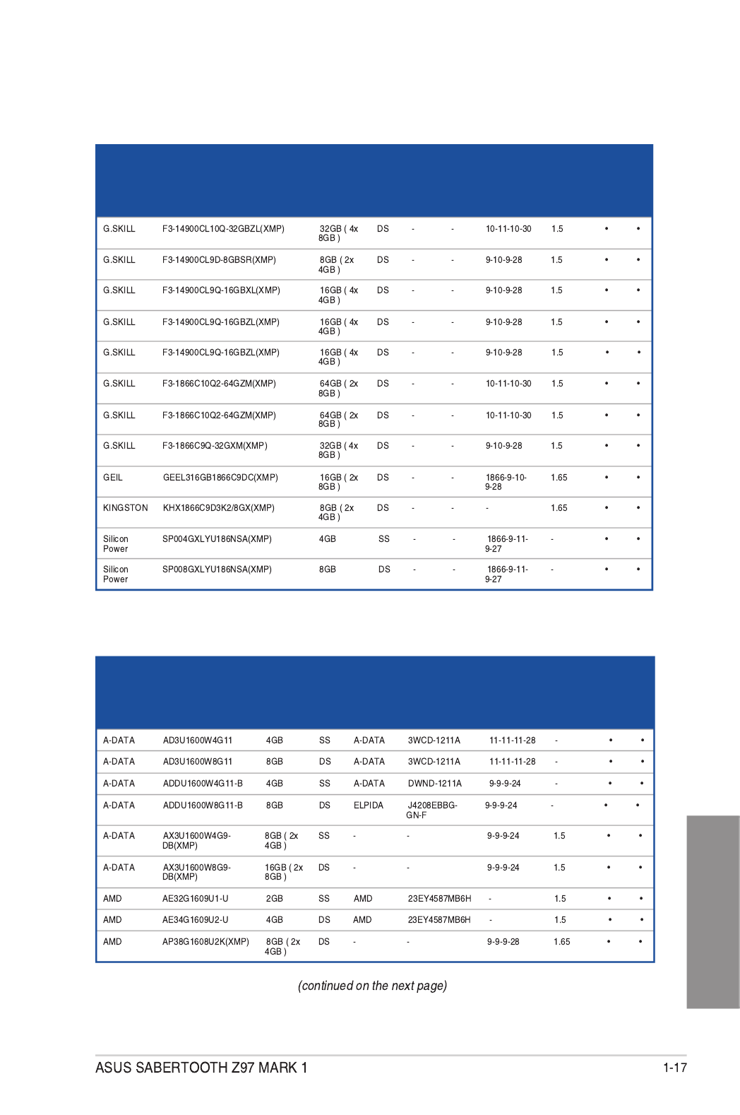
SABERTOOTH Z97 MARK 1 Motherboard Qualified Vendors Lists (QVL)
DDR3 2666 MHz capability
Vendors Part No. Size SS/
DS
Chip
Brand
Chip
NO. Timing Voltage
DIMM
socket
support
(Optional)
2 4
DDR3 2500 MHz capability
DDR3 2400 MHz capability
Vendors Part No. Size SS/
DS
Chip
Brand
Chip
NO. Timing Voltage
DIMM
socket
support
(Optional)
2 4
Vendors Part No. Size SS/
DS
Chip
Brand
Chip
NO. Timing Voltage
DIMM
socket
support
(Optional)
2 4

Chapter 1
DDR3 2400 MHz capability
Vendors Part No. Size SS/
DS
Chip
Brand
Chip
NO. Timing Voltage
DIMM
socket
support
(Optional)
2 4
DDR3 2200 MHz capability
Vendors Part No. Size SS/
DS
Chip
Brand
Chip
NO. Timing Voltage
DIMM
socket
support
(Optional)
2 4

Chapter 1
DDR3 2133 MHz capability
Vendors Part No. Size SS/
DS
Chip
Brand
Chip
NO. Timing Voltage
DIMM
socket
support
(Optional)
2 4
DDR3 2000 MHz capability
Vendors Part No. Size SS/
DS
Chip
Brand Chip NO. Timing Voltage
DIMM
socket
support
(Optional)
2 4

Chapter 1
DDR3 1866 MHz capability
Vendors Part No. Size SS/
DS
Chip
Brand
Chip
NO. Timing Voltage
DIMM
socket
support
(Optional)
2 4
Chapter 1
DDR3 1866 MHz capability
Vendors Part No. Size SS/
DS
Chip
Brand
Chip
NO. Timing Voltage
DIMM
socket
support
(Optional)
2 4
DDR3 1600 MHz capability
Vendors Part No. Size SS/
DS
Chip
Brand Chip NO. Timing Voltage
DIMM
socket
support
(Optional)
2 4

Chapter 1: Product introduction
Chapter 1
DDR3 1600 MHz capability
Vendors Part No. Size SS/
DS Chip
Brand Chip NO. Timing Voltage
DIMM
socket
support
(Optional)
2 4
• •
• •
• •
• •
• •
• •
SLA302G08-EGJ1C(XMP) 302G08-GJ1C • •
• •
• •
SLB304G08-EGJ1B(XMP) • •
• •
• •
• •
•
• •
• •
• •
• •
• •
• •
• •
• •
• •
• •
•
•
•
• •

ASUS SABERTOOTH Z97 MARK 1 1-19
Chapter 1
DDR3 1600 MHz capability
Vendors Part No. Size SS/
DS
Chip
Brand Chip NO. Timing Voltage
DIMM
socket
support
(Optional)
2 4
Crucial BLS4G3D1609DS1S00
.16FMR(XMP)
4GB DS - - 1600-9-
9-9-24
1.5 • •
Crucial BLT4G3D1608DT1TX0
.16FM(XMP)
4GB DS - - 8-8-8-24 1.5 • •
Elixir M2X2G64CB88G7N-
DG(XMP)
2GB SS Elixir N2CB2G80GN-DG 9-9-9-28 - • •
Elixir M2X4G64CB8HG5N-
DG(XMP) 4GB DS Elixir N2CB2G80GN-DG 9-9-9-28 - • •
G.SKILL F3-12800CL9D-
8GBSR2(XMP)
8GB (2x
4GB)
DS - - 9-9-9-24 1.25 • •
G.SKILL F3-12800CL9Q-
16GBXL(XMP)
16GB (4x
4GB)
DS - - 9-9-9-24 1.5 • •
G.Skill F3-12800CL9Q-
16GBZL(XMP)
16GB (4x
4GB)
DS - - 9-9-9-24 1.5 • •
G.SKILL F3-1600C9Q-32GXM(XMP) 32GB (4x
8GB)
DS - - - 1.5 • •
GEIL GUP34GB1600C7DC(XMP) 4GB (2x
2GB)
DS - - 7-7-7-24 1.6 • •
KINGMAX FLGE85F-C8KL9A(XMP) 2GB SS KINGMAX N/A 9-9-9-28 - • •
KINGMAX FLGF65F-C8KL9A(XMP) 4GB DS KINGMAX N/A 9-9-9-28 - • •
KINGSTON KHX16009CD3K2/8GX(XMP) 8GB (2x
4GB)
DS - - 1.659-9-9-27 • •
KINGSTON KHX1600C9D3B1/4G(XMP) 4GB SS - - 9-9-9-27 1.65 • •
KINGSTON 12GB (3x KHX1600C9D3K3/12GX(XMP)
4GB)
DS - - 9 1.65 •
KINGSTON KHX1600C9D3K3/6GX(XMP) 6GB (3x
2GB)
DS - - 9 1.65 • •
KINGSTON KHX1600C9D3K3/6GX(XMP) 6GB (3x
2GB)
DS - - 9 1.65 • •
KINGSTON 16GB (4x KHX1600C9D3K4/16GX(XMP)
4GB)
DS - - 9-9-9-24 1.65 • •
KINGSTON 24GB ( KHX1600C9D3K6/24GX(XMP)
6x 4GB)
DS - - 9 1.65 • •
KINGSTON 8GB (2x KHX1600C9D3LK2/8GX(XMP) 4GB) DS - - 9-9-9-24 1.35 • •
KINGSTON KHX1600C9D3P1K2/8G 8GB (2x
4GB)
DS - - 9 1.5 • •
KINGSTON KHX16C10B1K2/16X(XMP) 16GB (2x
8GB)
DS - - - 1.5 • •
KINGSTON KHX16C9K2/16 16GB (2x
8GB)
DS - - 1333-9-
9-9-24
1.5 • •
KINGSTON KHX16C9P1K2/16 16GB (2x
8GB)
DS - - - 1.5 • •
KINGSTON KVR16N11/4 4GB DS KINGSTON 11-11-D2568JPUCPGGBU 11-28-1 - • •
KINGSTON KVR16N11/4 4G DS Hynix - 1.5H5TQ2G83CFRPBC • •
Micron 8GB DS Micron - -MT16JTF1G64AZ-1G6E1 D9QBJ • •
Micron 4GB SS Micron - -MT8JTF51264AZ-1G6E1 D9QBJ • •
Micron MT8KTF25664AZ-1G6M1 2GB SS MICRON - -D9PFJ • •
(continued on the next page)

ASUS SABERTOOTH Z97 MARK 1 1-21
Chapter 1
DDR3 1333 MHz capability
Vendors Part No. Size SS/
DS Chip
Brand Chip NO. Timing Voltage
DIMM
socket
support
(Optional)
2 4
AMD AE32G1339U1-U 2GB SS AMD 23EY4587MB3H - 1.5 • •
AMD AE34G1339U2-U 4GB DS AMD 23EY4587MB3H - 1.5 • •
Apacer 78.B1GDE.9L10C 4GB DS Apacer 9 -AM5D5908CEHSBG • •
Asint 2GB SS ASint - -SLA302G08-EDJ1C 302G08-DJ1C • •
Asint 4GB SS Asint 9-10-SLA304G08-EDJ1B 304G08-DJ1B
10-26
- • •
Asint 8GB DS Asint 9-9-9-24 -SLB304G08-EDJ1B 304G08-DJ1B • •
BUFFALO D3U1333-1G 1GB SS Elpida - -J1108BFBG-DJ-F • •
BUFFALO D3U1333-2G 2GB DS Elpida -J1108BFBG-DJ-F • •
BUFFALO D3U1333-4G 4GB DS NANYA NT5CB256M8BN-
CG
- • •
CORSAIR CMV8GX3M1A1333C9 8GB DS - - 9-9-9-24 - • •
CORSAIR CMV8GX3M2A1333C9 8GB (2x
4GB)
DS - N/A 9-9-9-24 - • •
CORSAIR CMX4GX3M1A1333C9
(Ver2.12) 4GB (1x
4GB) DS - - 9-9-9-24 1.5 •
CORSAIR CMX4GX3M1A1333C9
(Ver5.11)
4GB (1x
4GB)
DS - - 9-9-9-24 1.5 •
CORSAIR CMX8GX3M1A1333C9
(Ver2.2)
8GB DS - - 9-9-9-24 1.5 •
CORSAIR 8GB (2x CMX8GX3M2A1333C9(XMP)
4GB)
DS - - 9-9-9-24 1.5 • •
G.SKILL F3-10666CL9D-8GBXL 8GB (2x
4GB)
DS - - 9-9-9-24 1.5 • •
GEIL GG34GB1333C9DC 4GB (2x
2GB )
DS GEIL 9-9-9-24 1.3GL1L128M88BA15B • •
GEIL GVP34GB1333C9DC 4GB (2x
2GB )
DS - - 9-9-9-24 1.5 • •
GEIL GVP38GB1333C9DC 8GB (2x
4GB)
DS - - 9-9-9-24 1.5 • •
INNODISK 2GB SS Hynix 9-9-9-24 -M3UN-2GHJBC09 H5TQ2G83CFRH9C • •
INNODISK 4GB DS Hynix 9-9-9-24 -M3UN-4GHJAC09 H5TQ2G83CFRH9C • •
KINGMAX FLFE85F-C8KL9 2GB SS KINGMAX KFC8FNLBF-
GXX-12A
- - • •
KINGMAX FLFE85F-C8KL9 2GB SS KINGMAX KFC8FNLXF-
DXX-15A
- - • •
KINGMAX FLFF65F-C8KL9 4GB DS KINGMAX KFC8FNLXF-
DXX-15A - - • •
KINGSTON KVR1333D3E9S/4G 4GB DS Elpida 9 1.5J2108ECSE-DJ-F • •
KINGSTON KVR1333D3N9H/4G 4GB DS ELPIDA - 1.5J2108BDBG-GN-F • •
KINGSTON KVR13N9S8H/4 4GB SS ELPIDA - 1.5J4208BBBG-GN-F • •
(continued on the next page)

1-22 Chapter 1: Product introduction
Chapter 1
DDR3 1333 MHz capability
Vendors Part No. Size SS/
DS Chip
Brand Chip NO. Timing Voltage
DIMM
socket
support
(Optional)
2 4
Mach
Xtreme
MXD3U133316GQ 16GB
( 4x
4GB )
DS - - - - • •
Mach
Xtreme
MXD3V13332GS 2GB SS Mach
Xtreme
C2S46D30-D313 - - • •
MICRON 2GB SS MICRON - -MT8JTF25664AZ-1G4M1 D9PFJ • •
Patriot PSD32G13332 2GB DS Patriot PM128M8D3BU-15 9 - •
RiDATA C304627CB1AG22Fe 2GB DS RiDATA C304627CB1AG22Fe 9 - • •
RiDATA E304459CB1AG32Cf 4GB DS RiDATA E304459CB1AG32Cf 9 - • •
Silicon
Power
SP001GBLTU133S02 1GB SS S-POWER 10YT3E5 9 - • •
Silicon
Power
SP002GBLTU133V02 2GB SS S-POWER 20YT3NG 9-9-9-24 - • •
Silicon
Power
SP004GBLTU133V02 4GB DS S-POWER 20YT3NG 9-9-9-24 - • •
UMAX 84E44G93UM-13BPSYW 4GB SS UMAX U2S96D30TP-13 1333-9-9-
9-24
- • •
UMAX 84E48G93UM-13BPSYW 8GB DS UMAX U2S96D30TP-13 1333-9-9-
9-24
- • •
Side(s): SS - Single-sided DS - Double-sided DIMM support:
(1) Supports one (1) module inserted into any slot as Single-channel memory
conguration. We suggest that you install the module into A1 slot.
(2) Supports two (2) modules inserted into either the beige slots or the brown slots as one
pair of Dual-channel memory conguration. We suggest that you install the modules
into slots A1 and B1 for better compatibility.
(4) Supports four (4) modules inserted into both the beige and brown slots as two pairs of
Dual-channel memory conguration.
• ASUS exclusively provides hyper DIMM support function.
• Hyper DIMM support is subject to the physical characteristics of individual CPUs. Load
the X.M.P. settings in the BIOS for the hyper DIMM support.
• Visit the ASUS website for the latest QVL.

ASUS SABERTOOTH Z97 MARK 1 1-23
Chapter 1
1.2.5 Expansion slots
Unplug the power cord before adding or removing expansion cards. Failure to do so may
cause you physical injury and damage motherboard components.
Slot No. Slot Description
1PCIe 2.0 x1_1 slot
2 PCIe 3.0/2.0 x16_1 slot
3PCIe 2.0 x1_2 slot
4 PCIe 3.0/2.0 x16_2 slot
5PCIe 2.0 x1_3 slot
6 PCIe 2.0 x16_3 slot

1-24 Chapter 1: Product introduction
Chapter 1
• We recommend that you provide sufcient power when running CrossFireX™ or SLI™
mode.
• Connect a chassis fan to the motherboard connector labeled CHA_FAN1-4 when
using multiple graphics cards for better thermal environment.
IRQ assignments for this motherboard
PCIe x16_3
Configuration
PCI Express sharing mode
PCIe x16_3 PCIe x1_3 Rear USB 3.0_E1~E2
x1 mode x1 x1 Enabled
x4 mode Disabledx4 Disabled
A B C D E F G H
PCIe x16_1 shared – – – – – – –
PCIe x16_2 – shared – – – – – –
PCIe x16_3 – – shared – – – – –
PCIe x1_1 – – – shared – – – –
PCIe x1_2 – – – shared – – – –
PCIe x1_3 – – shared – – – – –
SMBus Controller – – shared – – – – –
SATA #0 – – shared – – – –
GbE Controller – – – shared – – – –
EHCI #0 – – – – – – – shared
EHCI #1 shared – – – – – – –
XHCI Controller – – – – – shared – –
ASM1061
SATA6G(AHCI) – – – shared – – – –
Realtek 8111GR – – – shared – – – –
High Denition Audio – – – – – – shared –

ASUS SABERTOOTH Z97 MARK 1
Chapter 1
1.2.6 Onboard buttons
Onboard buttons allow you to ne-tune performance when working on a bare or open-
1. MemOK! button
• Onboard LEDs
•
•
•
•
recommended in the Memory QVL (Qualied Vendors Lists) in this user manual or
•
•
•

1-26 Chapter 1: Product introduction
Chapter 1
1.2.7 Jumpers
1. Clear RTC RAM (3-pin CLRTC)
This jumper allows you to clear the Real Time Clock (RTC) RAM in CMOS. You can
clear the CMOS memory of date, time, and system setup parameters by erasing
the CMOS RTC RAM data. The onboard button cell battery powers the RAM data in
CMOS, which include system setup information such as system passwords.
To erase the RTC RAM:
1. Turn OFF the computer and unplug the power cord.
2. Move the jumper cap from pins 1-2 (default) to pins 2-3. Keep the cap on pins 2-3 for
about 5-10 seconds, then move the cap back to pins 1-2.
3. Plug the power cord and turn ON the computer.
4. Hold down the <Delete> key during the boot process and enter BIOS setup to re-enter
data.
Except when clearing the RTC RAM, never remove the cap on CLRTC jumper default
position. Removing the cap will cause system boot failure!
• If the steps above do not help, remove the onboard battery and move the jumper
again to clear the CMOS RTC RAM data. After the CMOS clearance, reinstall the
battery.
• You do not need to clear the RTC when the system hangs due to overclocking. For
system failure due to overclocking, use the C.P.R. (CPU Parameter Recall) feature.
Shut down and reboot the system so the BIOS can automatically reset parameter
settings to default values.
• Due to the chipset behavior, AC power off is required to enable C.P.R. function. You
must turn off and on the power supply or unplug and plug the power cord before
rebooting the system.

ASUS SABERTOOTH Z97 MARK 1 1-27
Chapter 1
2. CPU Over Voltage jumper (3-pin CPU_OV)
The CPU Over Voltage jumper allows you to set a higher CPU voltage for a exible
overclocking system, depending on the type of the installed CPU. To gain more CPU
voltage setting, insert the jumper to pins 2-3. To go back to its default CPU voltage
setting, insert the jumper to pins 1-2.
1-28 Chapter 1: Product introduction
Chapter 1
1.2.8 Onboard LEDs
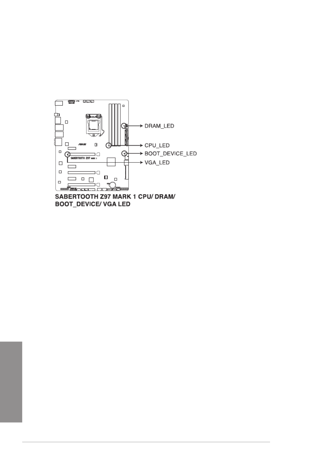
1. POST State LEDs
The POST State LEDs provide the status of these key components during POST
(Power-On-Self Test): CPU, memory modules, VGA card, and hard disk drives. If an
error is found, the critical component’s LED stays lit up until the problem is solved.

ASUS SABERTOOTH Z97 MARK 1 1-29
Chapter 1
1.2.9 Internal connectors
1. Intel ® Z97 Serial ATA 6.0 Gb/s connectors (7-pin SATA6G_1-2 [brown];
SATA6G_3-4 [black] SATA Express [black at the bottom])
These connectors connect to Serial ATA 6.0 Gb/s hard disk drives via Serial ATA 6.0
Gb/s signal cables.
If you installed Serial ATA hard disk drives, you can create a RAID 0, 1, 5, and 10
conguration with the Intel ® Rapid Storage Technology through the onboard Intel ® Z97
chipset.
• These connectors are set to [ ] by default. If you intend to create a Serial AHCI Mode
ATA RAID set using these connectors, set the SATA Mode item in the BIOS to
[ ]. Refer to section RAID Mode 3.6.3 SATA Configuration for details.
• Before creating a RAID set, refer to section or the manual 5.1 RAID configurations
bundled in the motherboard support DVD.

1-30 Chapter 1: Product introduction
Chapter 1
2. ASMedia ® Serial ATA 6.0 Gb/s connectors (7-pin SATA6G_E1-E2 [beige])
These connectors connect to Serial ATA 6.0 Gb/s hard disk drives via Serial ATA 6.0
Gb/s signal cables.
• ASMedia storage controller can only support AHCI mode.
• These SATA ports are for data drives only.
3. USB 3.0 connector (20-1 pin USB3_34)
This connector allows you to connect a USB 3.0 module for additional USB 3.0 front
or rear panel ports. With an installed USB 3.0 module, you can enjoy all the benets of
USB 3.0 including faster data transfer speeds of up to 5Gbps, faster charging time for
USB-chargeable devices, optimized power efciency, and backward compatibility with
USB 2.0.
• The USB 3.0 module is purchased separately.
• These connectors are based on xHCI specication. We recommend you to install the
related driver to fully use the USB 3.0 ports under Windows ® 7 or later Windows ® OS.

ASUS SABERTOOTH Z97 MARK 1 1-31
Chapter 1
4. Digital audio connector (4-1 pin SPDIF_OUT)
This connector is for an additional Sony/Philips Digital Interface (S/PDIF) port. Connect
the S/PDIF Out module cable to this connector, then install the module to a slot
opening at the back of the system chassis.
The S/PDIF module is purchased separately.

1-32 Chapter 1: Product introduction
Chapter 1
DO NOT connect a 1394 cable to the USB connectors. Doing so will damage the
motherboard!
You can connect the front panel USB cable to the ASUS Q-Connector (USB, dark brown)
rst, and then install the Q-Connector (USB) to the USB connector onboard if your chassis
supports front panel USB ports.
The USB 2.0 module is purchased separately.
5. USB 2.0 connectors (10-1 pin USB1112; USB1314)
These connectors are for USB 2.0 ports. Connect the USB module cable to any of
these connectors, then install the module to a slot opening at the back of the system
chassis. These USB connectors comply with USB 2.0 specication that supports up to
48 MBps connection speed.
ASUS SABERTOOTH Z97 MARK 1 1-33
Chapter 1
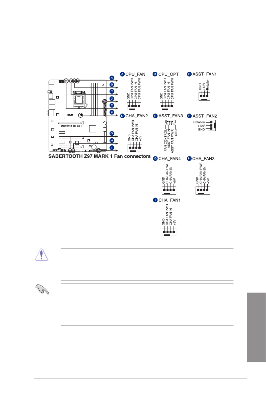
6. CPU, optional, chassis, and assistant fan connectors (4-pin CPU_FAN; 4-pin
CPU_OPT; 4-pin CHA_FAN1-4; 3-pin ASST_FAN1-2, 4-pin ASST_FAN3)
Connect the fan cables to the fan connectors on the motherboard.
• DO NOT forget to connect the fan cables to the fan connectors. Insufcient air
ow inside the system may damage the motherboard components. These are not
jumpers! Do not place jumper caps on the fan connectors!
• Ensure that the CPU FAN cable is securely installed to the CPU fan connector.
• The CPU_FAN connector supports the CPU fan of maximum 1A (12 W) fan power.
• The CPU_FAN, CHA_FAN and ASST_FAN connectors support the TUF Thermal
Radar 2 feature.
• To fully use the fan control function, ensure that you connect only an assistant fan to
the ASST_FAN connectors.

1-34 Chapter 1: Product introduction
Chapter 1
7. Front panel audio connector (10-1 pin AAFP)
This connector is for a chassis-mounted front panel audio I/O module that supports
either HD Audio or legacy AC`97 audio standard. Connect one end of the front panel
audio I/O module cable to this connector.
• We recommend that you connect a high-denition front panel audio module to this
connector to avail of the motherboard’s high-denition audio capability.
• If you want to connect a high-denition or an AC’97 front panel audio module to this
connector, set the Front Panel Type item in the BIOS setup to [ ] or [ ].HD AC97
8. Thermal Sensor connectors (2-pin T_SENSOR1; T_SENSOR2;T_SENSOR3)
These connectors are for the thermistor cables that monitor the temperature of the
devices and the critical components inside the motherboard. Connect the thermistor
cable and place the sensor on the device or the motherboard’s component to detect its
temperature.

ASUS SABERTOOTH Z97 MARK 1 1-35
Chapter 1
• For a fully congured system, we recommend that you use a power supply unit
(PSU) that complies with ATX 12 V Specication 2.0 (or later version) and provides a
minimum power of 350 W.
• DO NOT forget to connect the 4-pin/8-pin EATX12 V power plug. Otherwise, the
system will not boot.
• We recommend that you use a PSU with a higher power output when conguring a
system with more power-consuming devices. The system may become unstable or
may not boot up if the power is inadequate.
• If you want to use two or more high-end PCI Express x16 cards, use a PSU with
1000W power or above to ensure the system stability.
9. ATX power connectors (24-pin EATXPWR; 8-pin EATX12V)
These connectors are for ATX power supply plugs. The power supply plugs are
designed to t these connectors in only one orientation. Find the proper orientation and
push down rmly until the connectors completely t.

1-36 Chapter 1: Product introduction
Chapter 1
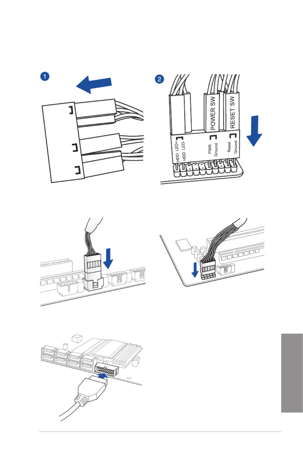
• SystempowerLED(2-pinPLED)
This 2-pin connector is for the system power LED. Connect the chassis power LED
cable to this connector. The system power LED lights up when you turn on the system
power, and blinks when the system is in sleep mode.
• HarddiskdriveactivityLED(2-pinIDE_LED)
This 2-pin connector is for the HDD Activity LED. Connect the HDD Activity LED cable
to this connector. The IDE LED lights up or ashes when data is read from or written to
the HDD.
• Systemwarningspeaker(4-pinSPEAKER)
This 4-pin connector is for the chassis-mounted system warning speaker. The speaker
allows you to hear system beeps and warnings.
• ATXpowerbutton/soft-offbutton(2-pinPWRSW)
This connector is for the system power button. Pressing the power button turns the
system on or puts the system in sleep or soft-off mode depending on the operating
system settings. Pressing the power switch for more than four seconds while the
system is ON turns the system OFF.
• Resetbutton(2-pinRESET)
This 2-pin connector is for the chassis-mounted reset button for system reboot without
turning off the system power.
10. System panel connector (20-8 pin PANEL)
This connector supports several chassis-mounted functions.

ASUS SABERTOOTH Z97 MARK 1 1-37
Chapter 1
11. TPM connector (20-1 pin TPM)
This connector supports a Trusted Platform Module (TPM) system, which securely
store keys, digital certicates, passwords and data. A TPM system also helps enhance
the network security, protects digital identities, and ensures platform integrity.
12. DirectKey connector (2-pin DRCT)
This connector is for the chassis-mounted button that supports the DirectKey function.
Connect the button cable that supports DirectKey, from the chassis to this connector on
the motherboard.
Ensure that your chassis comes with the extra button cable that supports the DirectKey
feature. Refer to the technical documentation that came with the chassis for details.
1-38 Chapter 1: Product introduction
Chapter 1
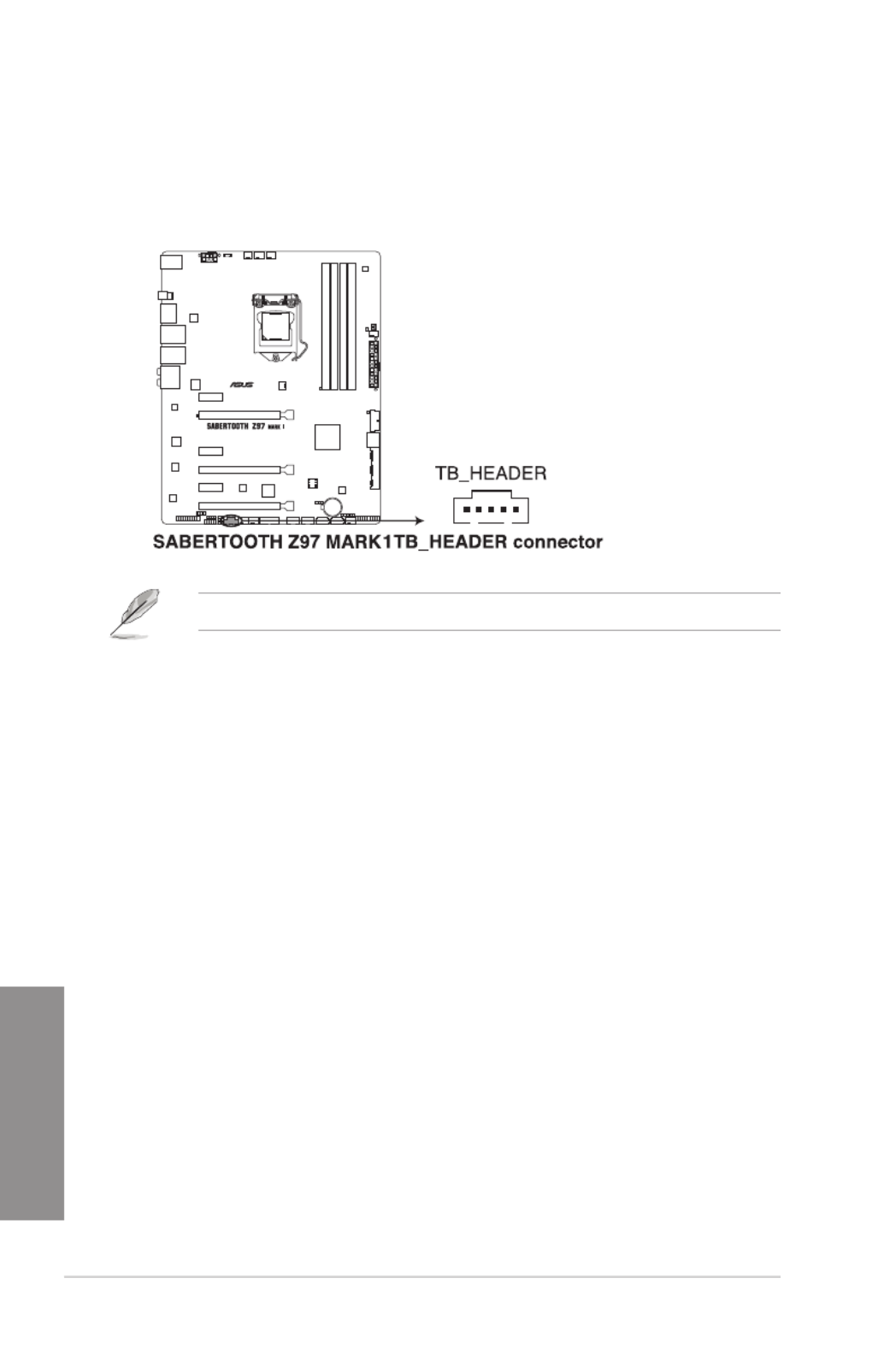
13. Thunderbolt header (5-pin TB_HEADER)
This connector is for the add-on Thunderbolt I/O card that supports Intel’s Thunderbolt
Technology, allowing you to connect up to six Thunderbolt-enabled devices and a
DisplayPort-enabled display in a daisy-chain conguration.
The add-on Thunderbolt I/O card and Thunderbolt cables are purchased separately.
2-4 Chapter 2: Basic installation
Chapter 2
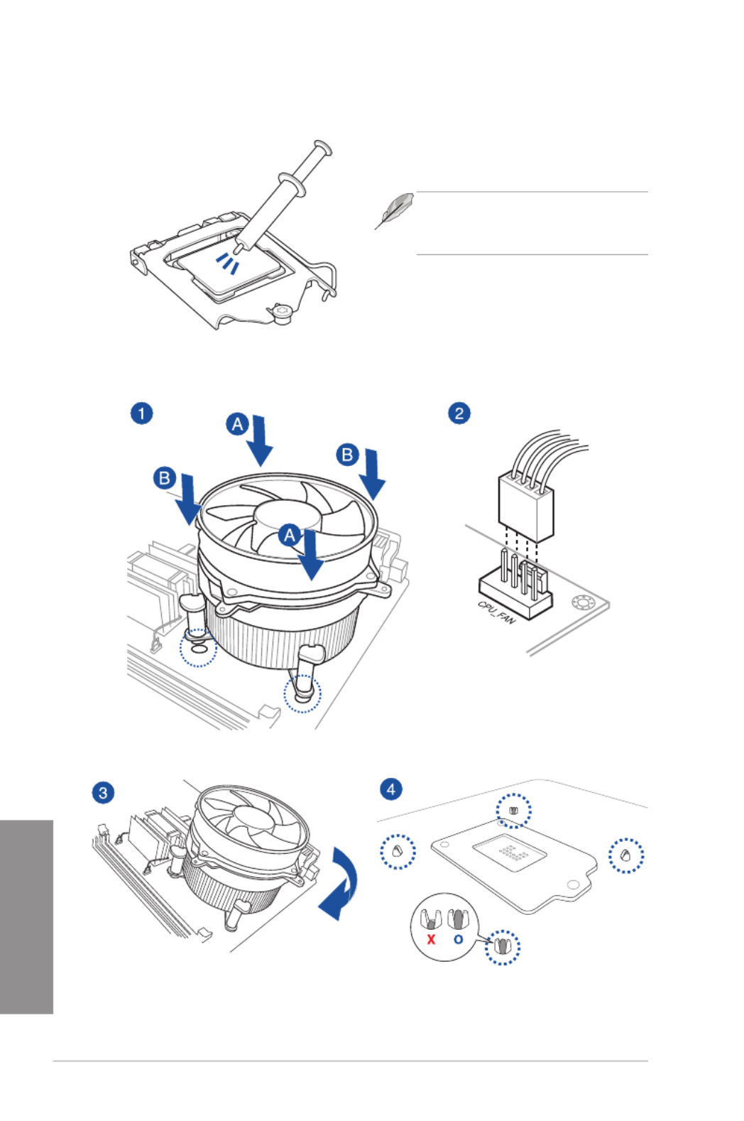
2.1.3 CPU heatsink and fan assembly installation
Apply the Thermal Interface Material to the
CPU heatsink and CPU before you install
the heatsink and fan, if necessary.
To install the CPU heatsink and fan assembly

ASUS SABERTOOTH Z97 MARK 1 2-5
Chapter 2
To uninstall the CPU heatsink and fan assembly

2-6 Chapter 2: Basic installation
Chapter 2
To remove a DIMM
2.1.4 DIMM installation

ASUS SABERTOOTH Z97 MARK 1 2-7
Chapter 2
2.1.5 ATX Power connection
OR OR
2-8 Chapter 2: Basic installation
Chapter 2
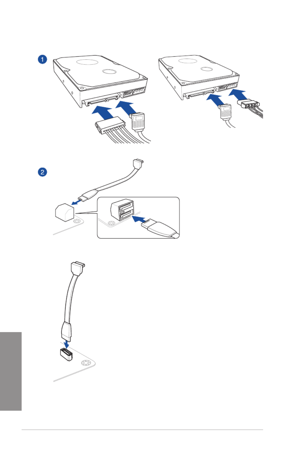
2.1.6 SATA device connection
OR
OR
ASUS SABERTOOTH Z97 MARK 1 2-9
Chapter 2
2.1.7 Front I/O Connector
To install ASUS Q-Connector
USB 2.0
AAFP
To install USB 2.0 connector To install front panel audio connector
To install USB 3.0 connector
HDD LED
POWER SW
RESET SW
HDD LED-
HDD LED+
PWR
Reset
Ground
Ground
HDD LED
USB 3.0
Chapter 2
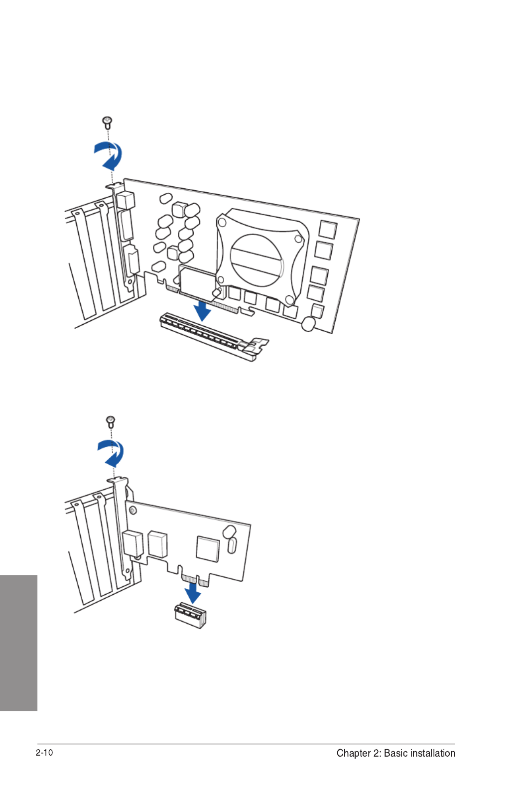
2.1.8 Expansion Card installation
To install PCIe x16 cards
To install PCIe p62-x1 cards
Chapter 2
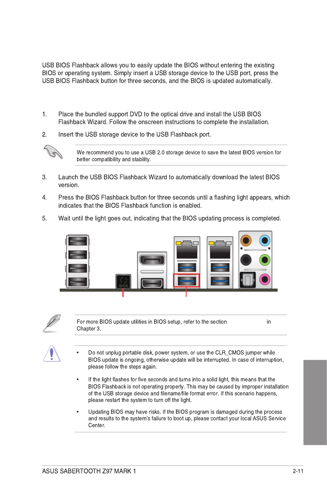
2.2 BIOS update utility
USB BIOS Flashback
To use USB BIOS Flashback:
Updating BIOS
USB BIOS Flashback port
USB BIOS Flashback button

Chapter 2
2.3 Motherboard rear and audio connections
2.3.1 Rear I/O connection
* and **: Refer to the tables on the next page for LAN port LEDs, and audio port definitions.
Rear panel connectors

Chapter 2
2.3.2 Audio I/O connections
Audio I/O ports
Connect to Headphone and Mic
Connect to Stereo Speakers
Connect to 2.1 channel Speakers

ASUS SABERTOOTH Z97 MARK 1
Chapter 2
Connect to 4.1 channel Speakers
Connect to 5.1 channel Speakers
Connect to 7.1 channel Speakers

Chapter 2
2.4 Starting up for the first time
BIOS Beep Description
2.5 Turning off the computer
Chapter 3
DO NOT change the default BIOS settings
We strongly
recommend that you change the BIOS settings only with the help of a trained service
personnel
Z97ST.CAP
BIOS setup
3.1 Knowing BIOS
Chapter 3: BIOS setup
Chapter 3
Load Optimized
Defaults Exit <F5> 3.10 Exit Menu
1.2.6 Onboard buttons and
switches
BIOS menu screen
EZ Mode Advanced Mode
Exit Exit/Advanced Mode
3.2 BIOS setup program
Entering BIOS at startup
Entering BIOS Setup after POST

Chapter 3
3.2.1 EZ Mode
Exit/Advanced Mode Advanced Mode
3.8 Boot menu
Saves the changes and
resets the system
Selects the display language
of the BIOS setup program
Displays the CPU/motherboard temperature,
CPU voltage output, CPU/chassis/power fan
speed, and SATA information
Displays the system properties of the selected mode.
Click < or > to switch EZ System Tuning modes
Displays the Advanced
mode menus
Selects the boot
device priority
Loads optimized
default settings
Creates storage RAID and
configures system overclocking
Shows the
bootable devices
Displays the CPU Fan’s speed. Click
the button to manually tune the fans
Enables or disables the SATA RAID mode
for Intel Rapid Storage Technology
Chapter 3
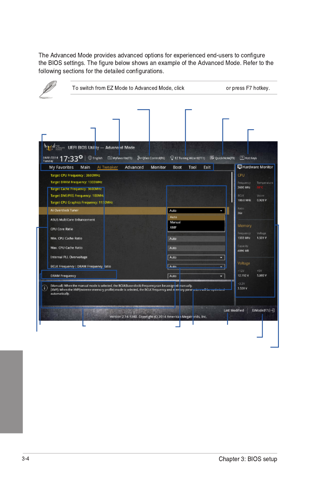
3.2.2 Advanced Mode
Advanced Mode
Configuration fields
Menu bar
Item descriptionSub-menu item
Menu items
Scroll bar Last modified settings
Language
EZ Tuning Wizard
MyFavorite Quick Note
Hot Keys
Goes back to EZ Mode
Displays the CPU/motherboard temperature,
CPU and memory voltage output
Q-Fan control

Chapter 3
Menu bar
My Favorites
Main
Ai Tweaker
Advanced
Monitor
Boot
Tool
Exit
Menu items
Main
Submenu items
Language
MyFavorites (F3)
3.3 My Favorites
Q-Fan Control (F6)
3.2.3 QFan Control
EZ Tuning Wizard (F11)
3.2.4 EZ Tuning Wizard

Chapter 3
Quick Note (F9)
Hot keys
Scroll bar
General help
Configuration fields
Last Modified button
Chapter 3
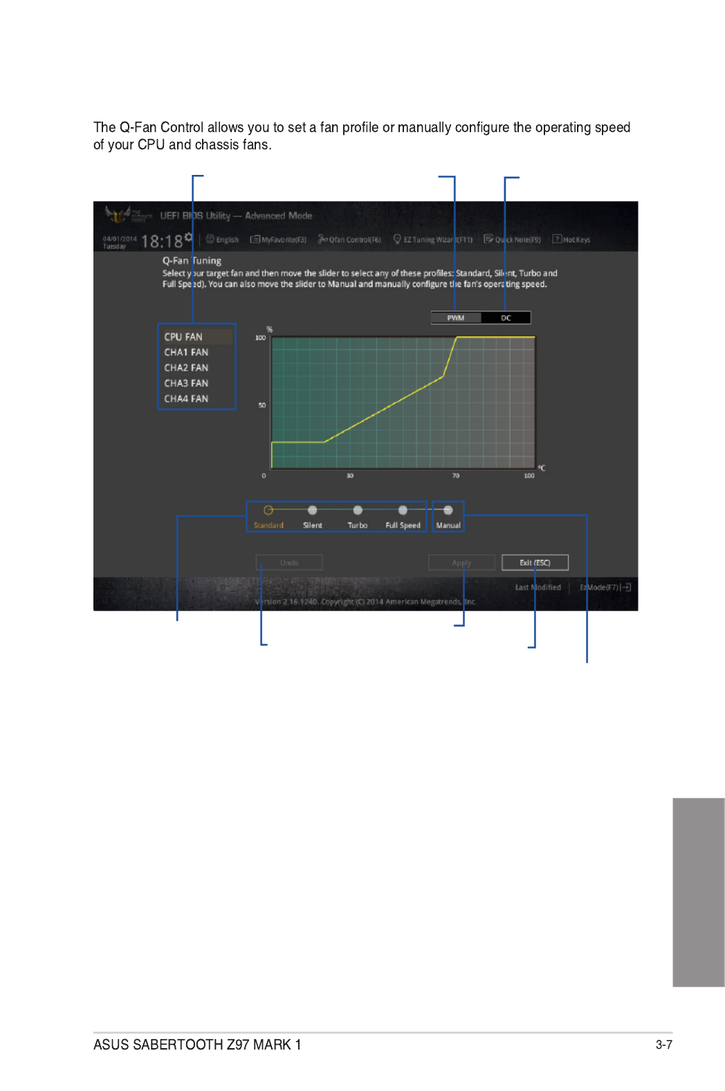
3.2.3 Q-Fan Control
Click to select a fan to be
configured Click to activate
PWM Mode
Click to undo the
changes
Click to apply the fan setting
Click to go back to main menu
Select a profile to apply to
your fans
Click to activate DC Mode
Select to manually configure
your fans
Chapter 3
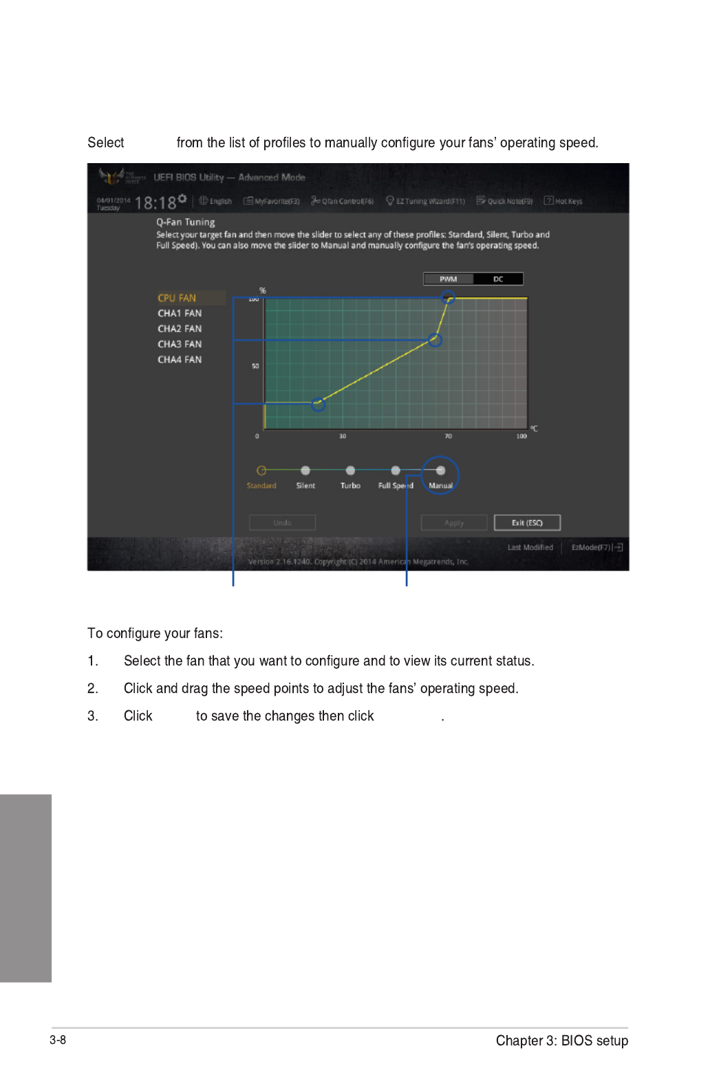
Configuring fans manually
Manual
Apply Exit (ESC)
Speed points Click or tap to manually
configure your fans

Chapter 3
3.2.4 EZ Tuning Wizard
Tuning your system settings
Next
Daily Computing Gaming/Media Editing Next
Box cooler Tower cooler Water cooler
Next
I’m not sure
Next Yes
System OC setup RAID setup

Chapter 3
3.3 My Favorites

Chapter 3
Administrator Password
If you have set an administrator password, we recommend that you enter the administrator
password for accessing the system. Otherwise, you might be able to see or change only
selected elds in the BIOS setup program.
To set an administrator password:
1. Select the item and press <Enter>.Administrator Password
2. From the box, key in a password, then press <Enter>.Create New Password
3. Conrm the password when prompted.
To change an administrator password:
1. Select the item and press <Enter>.Administrator Password
2. From the box, key in the current password, then press Enter Current Password
<Enter>.
3. From the box, key in a new password, then press <Enter>.Create New Password
4. Conrm the password when prompted.
To clear the administrator password, follow the same steps as in changing an administrator
password, but press <Enter> when prompted to create/conrm the password. After you clear
the password, the item on top of the screen shows .Administrator Password Not Installed
User Password
If you have set a user password, you must enter the user password for accessing the system.
The User Password item on top of the screen shows the default Not Installed. After you set a
password, this item shows Installed.
To set a user password:
1. Select the item and press <Enter>.User Password
2. From the box, key in a password, then press <Enter>.Create New Password
3. Conrm the password when prompted.

ASUS SABERTOOTH Z97 MARK 1 3-21
Chapter 3
Skew Control
This item contains the transmitter and receiver’s rising and falling slopes and their time
controllers. Adjust these items to enhance the DRAM overclocking capability and stability.
Use the <+> or <-> keys to adjust the value.
Transmitter Rising Slope [Auto]
Conguration options: [Auto] [0] - [31]
Transmitter Falling Slope [Auto]
Conguration options: [Auto] [0] - [31]
Transmitter Control Time [Auto]
Conguration options: [Auto] [0] - [31]
Receiver Rising Slope [Auto]
Conguration options: [Auto] [0] - [31]
Receiver Falling Slope [Auto]
Conguration options: [Auto] [0] - [31]
Receiver Control Time [Auto]
Conguration options: [Auto] [0] - [31]
External DIGI+ Power Control
CPU Load-line Calibration [Auto]
Load-line is dened by Intel ® specication and affects CPU power voltage. The CPU
working voltage decreases proportionally to CPU loading. Higher load-line calibration
could get higher voltage and good overclocking performance, but increases the CPU
and VRM thermal conditions. Select from levels 1 to 9 to adjust the CPU power voltage
from 0% to 125%.
Conguration options [Auto] [Level 1] - [Level 9]
The actual performance boost may vary depending on your CPU specication.
DO NOT remove the thermal module. The thermal conditions should be monitored.
CPU VRM Switching Frequency [Auto]
This item affects the VRM transient response speed and the component thermal
production. Select [Manual] to congure a higher frequency for a quicker transient
response speed.
Conguration options: [Auto] [Manual]
DO NOT remove the thermal module. The thermal conditions should be monitored.

ASUS SABERTOOTH Z97 MARK 1 3-31
Chapter 3
3.6.1 CPU Configuration
The items in this menu show the CPU-related information that the BIOS automatically
detects.
The items in this menu may vary based on the CPU installed.
Intel Adaptive Thermal Monitor [Enabled]
This item allows you to protect the CPU by decreasing its frequency as it reaches the thermal
throttle point. The thermal monitor includes TM1 (Thermal monitor 1), TM2 (Thermal monitor
2), and EMTTM (Enhanced Multi-threaded Thermal Monitoring).
Conguration options: [Disabled] [Enabled]
Hyper-threading [Enabled]
This item allows the processor to appear as two logical processors, allowing the operating
system to schedule two threads or processes simultaneously.
Conguration options: [Disabled] [Enabled]
Active Processor Cores [All]
This item allows you to select the number of CPU cores to activate in each processor
package.
Conguration options: [All] [1] [2] [3]
Limit CPUID Maximum [Disabled]
When set to , this item allows the legacy OS to boot even without support for CPUs [Enabled]
with extended CPUID functions.
Conguration options: [Disabled] [Enabled]
Produkt Specifikationer
| Mærke: | Asus |
| Kategori: | Bundkort |
| Model: | Sabertooth Z97 MARK1 |
Har du brug for hjælp?
Hvis du har brug for hjælp til Asus Sabertooth Z97 MARK1 stil et spørgsmål nedenfor, og andre brugere vil svare dig
Bundkort Asus Manualer

27 Marts 2025
15 Februar 2025
12 Februar 2025
12 Februar 2025
12 Februar 2025
12 Februar 2025
6 Februar 2025
6 Februar 2025
6 Februar 2025
6 Februar 2025
Bundkort Manualer
- Bundkort Gigabyte
- Bundkort Asrock
- Bundkort MSI
- Bundkort NZXT
- Bundkort ECS
- Bundkort Sapphire
- Bundkort Intel
- Bundkort Sharkoon
- Bundkort Supermicro
- Bundkort Biostar
- Bundkort Evga
- Bundkort Foxconn
- Bundkort Advantech
- Bundkort Elitegroup
- Bundkort EPoX
- Bundkort AOpen
- Bundkort Raspberry Pi
Nyeste Bundkort Manualer

29 Marts 2025
6 Marts 2025

15 Februar 2025
15 Februar 2025
15 Februar 2025
15 Februar 2025
15 Februar 2025
15 Februar 2025
12 Februar 2025
12 Februar 2025