Asus TS300-E8-PS4 Manual
Læs nedenfor 📖 manual på dansk for Asus TS300-E8-PS4 (172 sider) i kategorien Server. Denne guide var nyttig for 8 personer og blev bedømt med 4.5 stjerner i gennemsnit af 2 brugere
Side 1/172

5U Rackmount Server
User Guide
TS300-E8-PS4
Copyright © 2016 ASUSTeK COMPUTER INC. All Rights Reserved.

Contents
Safety information viii ....................................................................................................
About this guide ix .........................................................................................................
Chapter 1: Product Introduction
1.1 System package contents 1-2 .........................................................................
1.2 Serial number label 1-3 ....................................................................................
1.3 System specifications 1-4 ...............................................................................
1.4 Front panel features 1-6 ...................................................................................
1.5 Rear panel features 1-7 ....................................................................................
1.6 Internal features 1-8 .........................................................................................
1.7 LED information 1-9 .........................................................................................
Chapter 2: Hardware Information
2.1 Chassis cover 2-2 .............................................................................................
2.2 Central Processing Unit (CPU) 2-4 .................................................................
2.3 System memory 2-9 .........................................................................................
2.4 Front panel assembly 2-11 ..............................................................................
2.5 5.25-inch drives 2-12 ........................................................................................
Contents
2.6 SATA/SAS hard disk drives 2-13 ....................................................................
2.7 Expansion cards 2-19 ......................................................................................
2.8 Cable connections 2-23 ...................................................................................
2.9 Removable components 2-26 ..........................................................................
Chapter 3: Installation Options
3.1 Preparing the system for rack mounting 3-2 .................................................
3.2 Attaching the inner rail to the server 3-3 .......................................................
3.3 Attaching the rails to the rack 3-4 ..................................................................
3.4 Mounting the server to the rack 3-5 ...............................................................

Chapter 4: Motherboard Information
4.1 Motherboard overview 4-2 ...............................................................................
4.2 Expansion slots 4-6 ..........................................................................................
4.3 Onboard LEDs 4-8 ............................................................................................
4.4 Jumpers .................................................................................................... 4-11
4.5 Internal connectors 4-16 ..................................................................................
Chapter 5: BIOS Setup
5.1 Managing and updating your BIOS 5-2 ..........................................................
5.2 BIOS setup program 5-6 ..................................................................................
Contents

Contents
5.3 Main menu 5-9 ..................................................................................................
5.4 Advanced menu 5-10 .......................................................................................
5.5 Event Logs menu 5-30 .....................................................................................
5.6 Boot menu 5-31 ................................................................................................
5.7 Monitor menu 5-34 ...........................................................................................
5.8 Security ..................................................................................................... 5-35
5.9 Tool menu 5-38 .................................................................................................
5.10 Exit menu 5-38 ..................................................................................................
Chapter 6: RAID Configuration
6.1 Setting up RAID 6-2 ..........................................................................................
Contents
6.2 Intel® Rapid Storage Technology enterprise
SATA Option ROM Utility...........................................................................6-4
6.3 Intel® Rapid Storage Technology enterprise (Windows) 6-12 ......................
Chapter 7: Driver Installation
7.1 RAID driver installation 7-2 .............................................................................
7.2 Management applications and utilities installation 7-6 ................................
7.3 Running the Support DVD 7-6 .........................................................................
7.4 Installing the LAN driver 7-14 ..........................................................................
7.5 Installing the VGA driver 7-19 .........................................................................
7.6 Installing the Intel® C22x MEI NULL HECI driver 7-22 ...................................
7.7 Installing the Intel® I210 Gigabit Adapter driver 7-24 ....................................
Appendix
Notices A-2 ....................................................................................................................
ASUS contact information A-4 ......................................................................................
Safety information
Electrical Safety
Operation Safety
CLASS 1 LASER PRODUCT

About this guide
Audience
Contents
1. Chapter 1: Product Introduction
2. Chapter 2: Hardware Information
3. Chapter 3: Installation Options
4. Chapter 4: Motherboard Information
5. Chapter 5: BIOS Setup
6. Chapter 6: RAID Configuration
7. Chapter 7: Driver Installation

References
1. ASUS Server Web-based Management (ASWM) user guide
2. ASUS websites
Conventions
Typography
Bold text
Command
format A:/S
DANGER/WARNING:
CAUTION:
NOTE:
IMPORTANT:

Product Introduction
Chapter 1: Product Introduction
*ASUS System Web-based Management
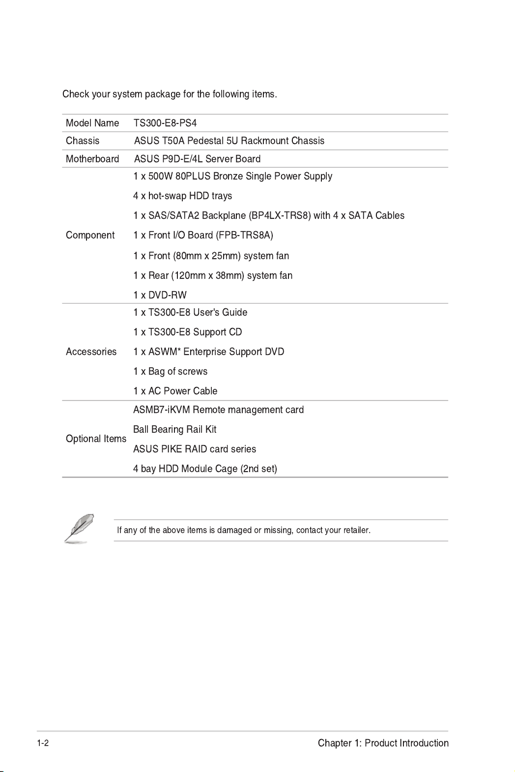
1.1 System package contents

1.2 Serial number label
xxS0xxxxxxxx
TS300-E8-PS4

1.3 System specifications
Model Name TS300-E8-PS4
Processor Support
Core Logic
Memory
Total Slots
Capacity
Memory Type
Memory Size
Expansion
Slots
Total PCI / PCI-X /
PCI-E Slots
Slot Type
Additional Slot 1
Storage
SATA Controller
Intel
® C224
SAS Controller
Optional kits:
HDD Bays
I = internal
A or S = hot-
swappable
Networking LAN
Graphic VGA

*Specifications are subject to change without notice.
Model Name TS300-E8-PS4
Auxiliary Storage
FDD / CD / DVD
Onboard I/O
Management
Solution
Software
Out of Band
Remote
Management
Dimension
(HH X WW X DD)
Net Weight Kg
(CPU, DRAM & HDD not
included)
Power Supply
Environment

1.4 Front panel features
Empty 5.25-inch bays
Power button
Reset button
Security lock
4-bay HDD cage
4-bay HDD cage
(Optional Set)
1.7.1 Front panel LEDs
USB 2.0 ports
USB 3.0 ports
Headset port*
Mic In port*
Locate LED
LAN2 LED
LAN1 LED
Optical drive
Message LED
HDD access LED
Power LED

1.5 Rear panel features
Expansion slots
Chassis intrusion switch
120mm x 38mm system fan
* This port is for the ASUS ASMB7-iKVM controller card only.
Chassis lock
Power connector
PS/2 mouse/keyboard port
USB 2.0 ports
VGA port
Gigabit LAN port 1
USB 3.0 ports
COM port
Gigabit LAN port 2
Gigabit LAN port 3
Gigabit LAN port 4
LAN port 5*
500W (80Plus) Bronze
Single power supply
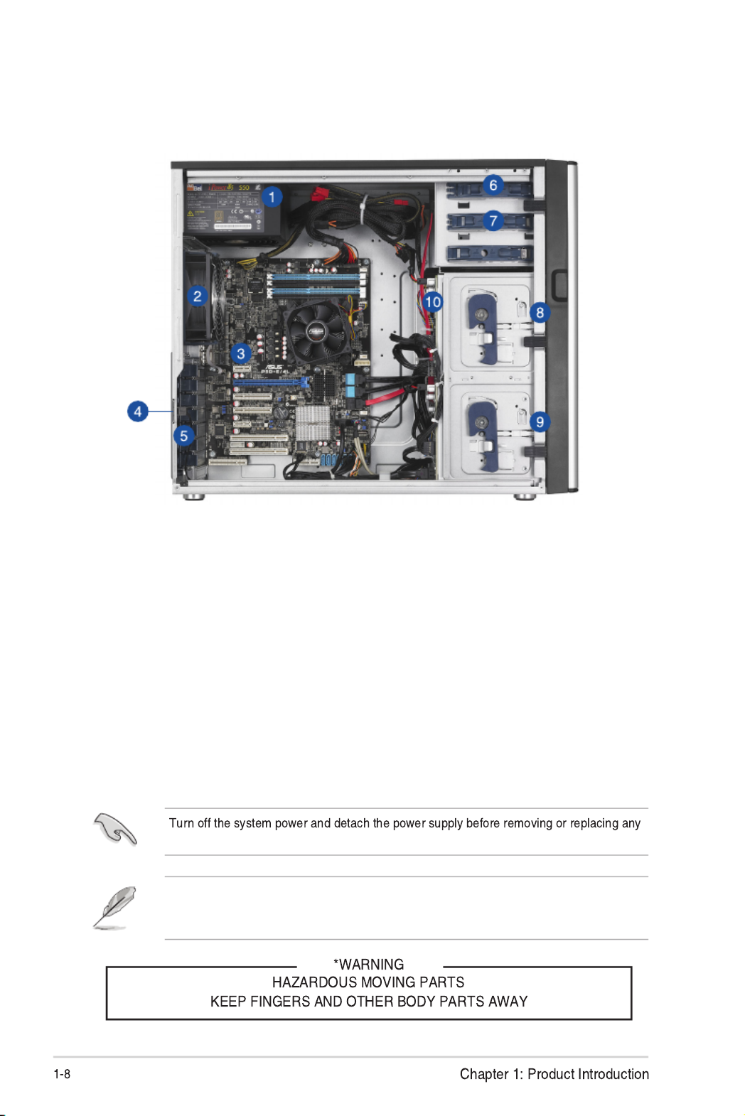
system component.
The barebone server does not include a oppy disk drive and an optical disc drive. Connect
a USB oppy disk drive or a USB ODD to any of the USB ports on the front or rear panel if
you need to use a oppy disk or an optical disc.
1.6 Internal features
The barebone server includes the basic components as shown.
1. 500W (80 Plus) Bronze Single Power supply unit
2. 120mm x 38mm system fan (ARX FD1212-DP284G)
3. ASUS P9D-E/4L Server Board
4. Chassis intrusion switch
5. Expansion card locks
6. Optical drive
7. 2 x 5.25-inch drive bays
8. 4-bay HDD module (rst set)
9. 4-bay HDD module (second set, optional)
10. SATA/SAS backplane board (rst set, hidden)
ASUS TS300-E8-PS4 1-9
1.7 LED information
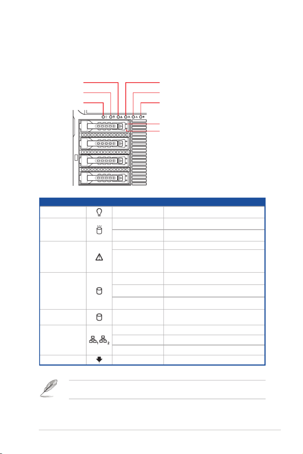
1.7.1 Front panel LEDs
HDD Status LED
LED Icon Display status Description
Power LED ON System power ON
HDD Access LED OFF No activity
Blinking Read/write data into the HDD
Message LED
OFF System is normal; no incoming event
Lighting up
A hardware temperature overheat is
detected. Use ASWM to check the
abnormal status.
HDD Status LED
Green SATAII/SAS HDD power on
Red HDD failure
Green/Red Blinking RAID rebuilding
HDD Activity LED Green Blinking Read/write data from/into the SATAII/
SAS HDD
LAN LEDs
OFF No LAN connection
Blinking LAN accessing
ON LAN connection is present
Locate LED Blinking Problem with the server is detected
1 2
Locate LED
LAN2 LED
LAN1 LEDMessage LED
HDD access LED
Power LED
The Power, HDD Access, LAN and Message LEDs are visible even if the system front
bezel is closed.
HDD Activity LED
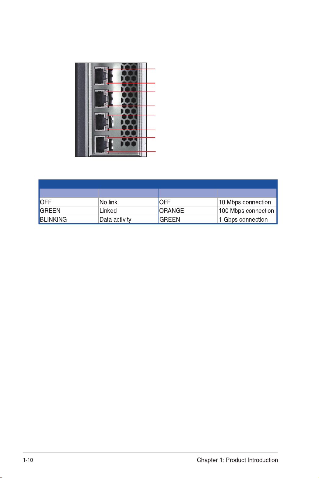
1.7.2 Rear panel LEDs
ACT/LINK LED SPEED LED
Status Description Status Description
SPEED LED
ACT/LINK LED
SPEED LED
ACT/LINK LED
SPEED LED
ACT/LINK LED
SPEED LED
ACT/LINK LED

Hardware Information
Chapter 2: Hardware Information

2.1 Chassis cover
2.1.1 Removing the side cover
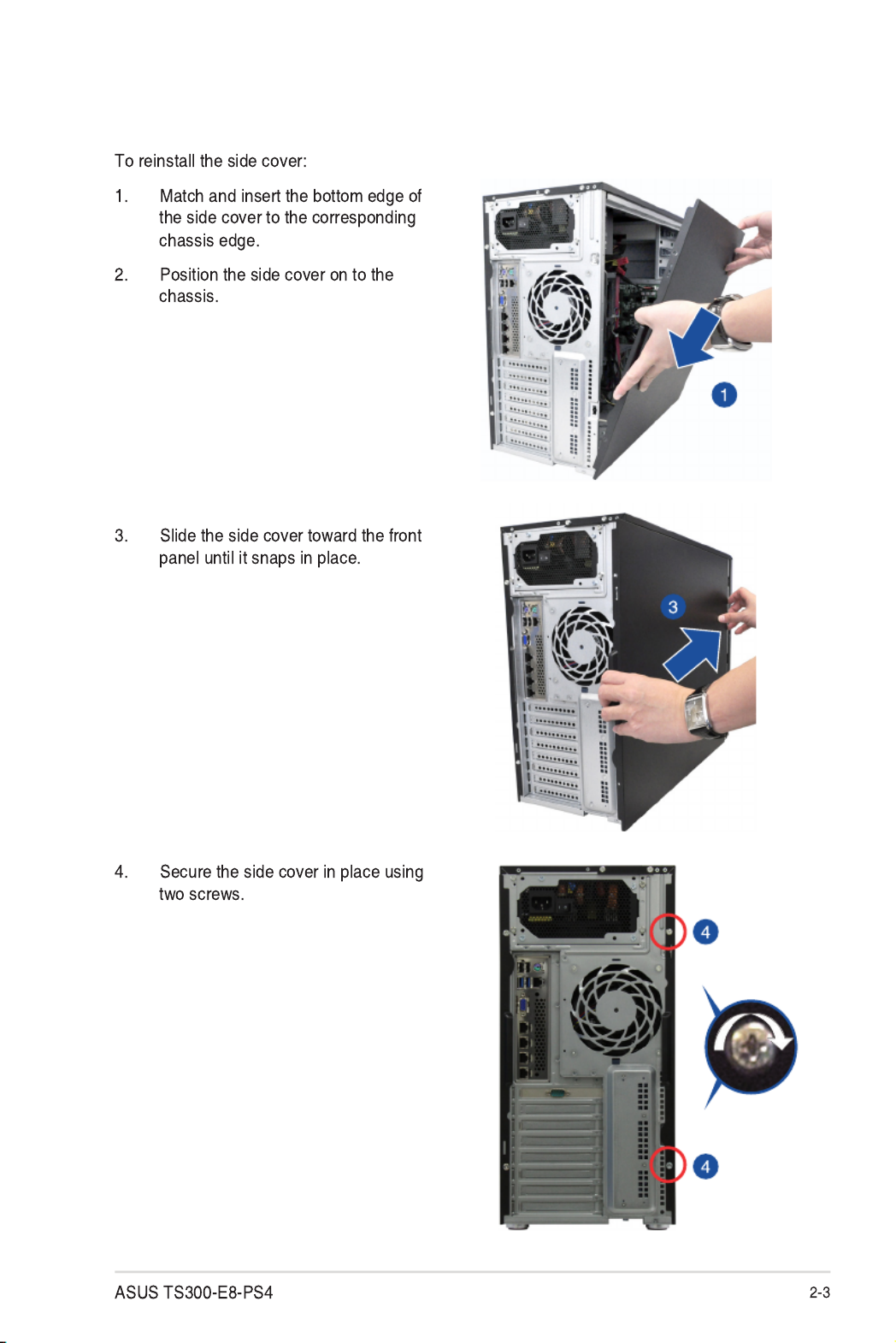
2.1.2 Reinstalling the side cover

2.2.1 Installing the CPU
2.2 Central Processing Unit (CPU)

Load plate
Gold
triangle
mark
CPU notches
Alignment
key
Alignment key
Retention tab
Load lever

Retention
lock
Load lever
Retention tab
Load lever
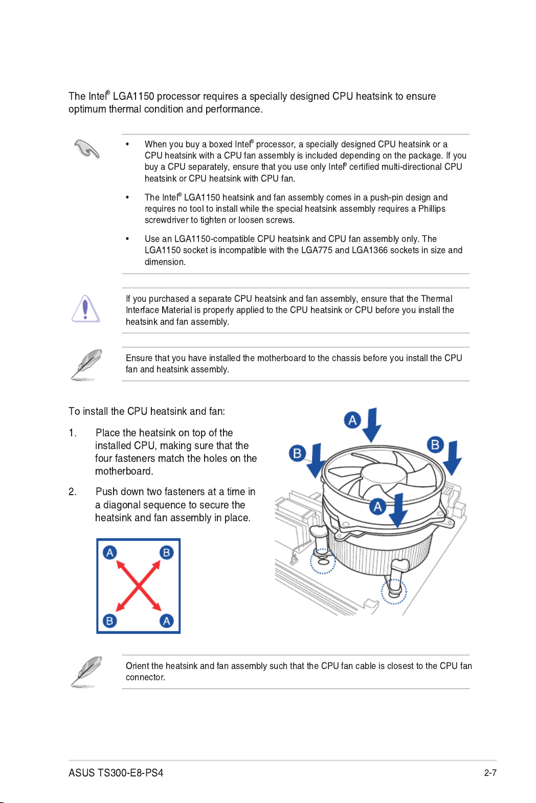
2.2.2 Installing the CPU heatsink

2.2.3 Uninstalling the CPU heatsink and fan
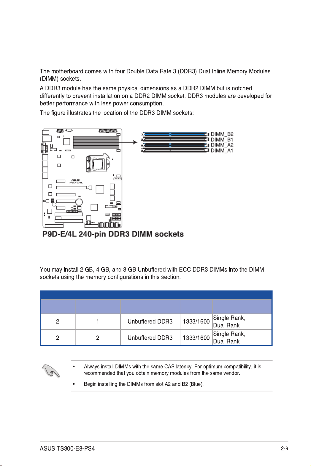
2.3 System memory
2.3.1 Overview
2.3.2 Memory Configurations
UDIMM
DIMM Slot Per
Channel
DIMM Populated
per Channel DIMM Type Speed Rank per DIMM

2.3.3 Installing a DIMM on a single clip DIMM socket
Locked Retaining Clip
DIMM notch
DIMM slot key Unlocked retaining clip
2.3.4 Removing a DIMM from a single clip DIMM socket

2.4 Front panel assembly
2.4.1 Removing the front panel assembly
2.4.2 Reinstalling the front panel assembly

2.5 5.25-inch drives
2.5.1 Installing a 5.25-inch drive

2.6 SATA/SAS hard disk drives
2.6.1 Installing the HDD module cage
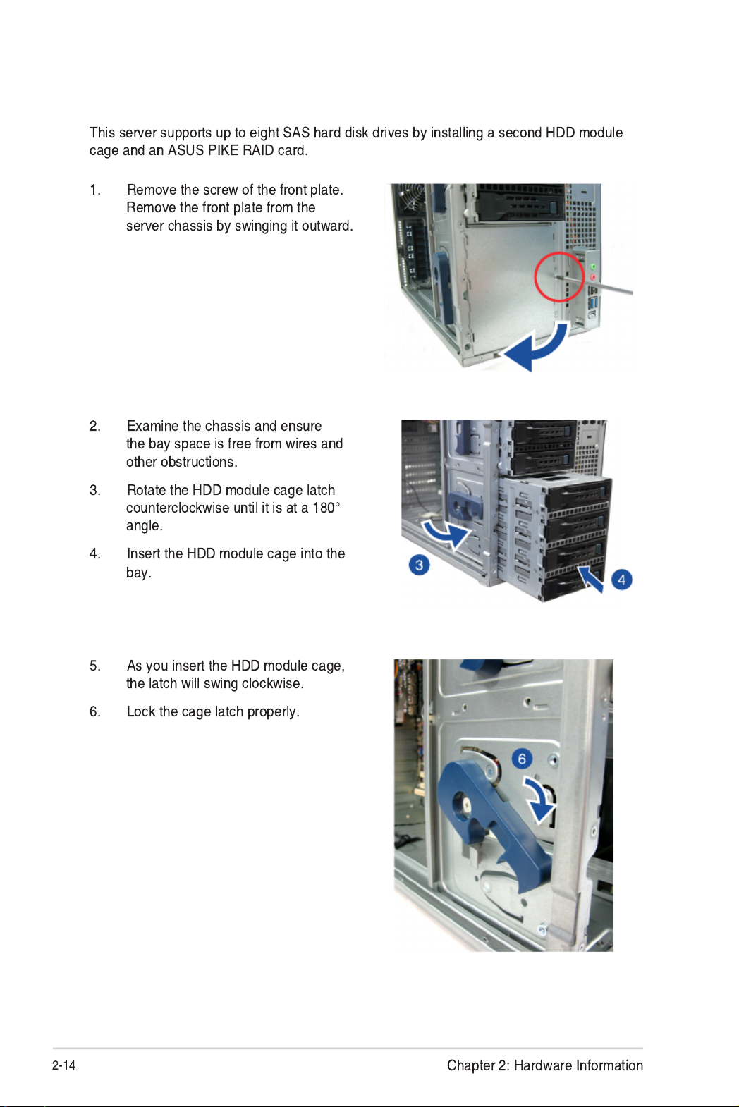
2.6.2 Installing the second HDD module cage (Optional)

2.7.2 Installing an ASUS
PIKE RAID card
8-1 pin cable end
10-1 pin cable end
2.8.1 Motherboard connections
2.8.2 SATA/SAS backplane connections

2.6.3 Removing the HDD module cage
2.6.4 Installing a hot-swap SATA/SAS hard disk drive

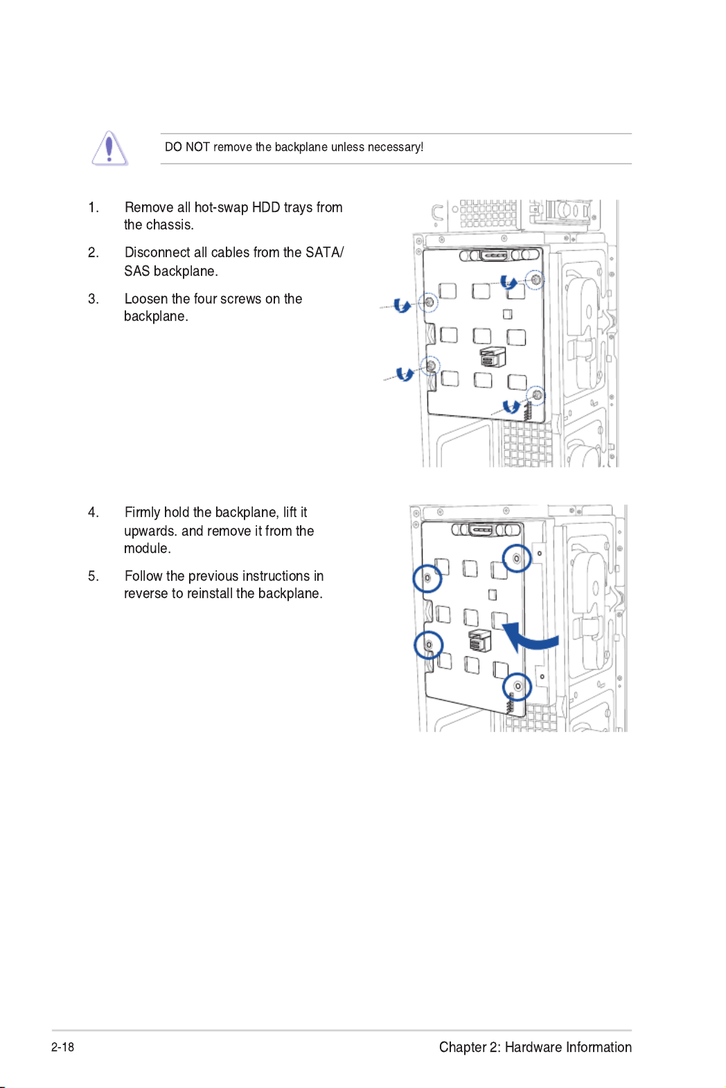
2.6.5 Removing and reinstalling the backplane

2.7 Expansion cards
2.7.1 Installing an expansion card
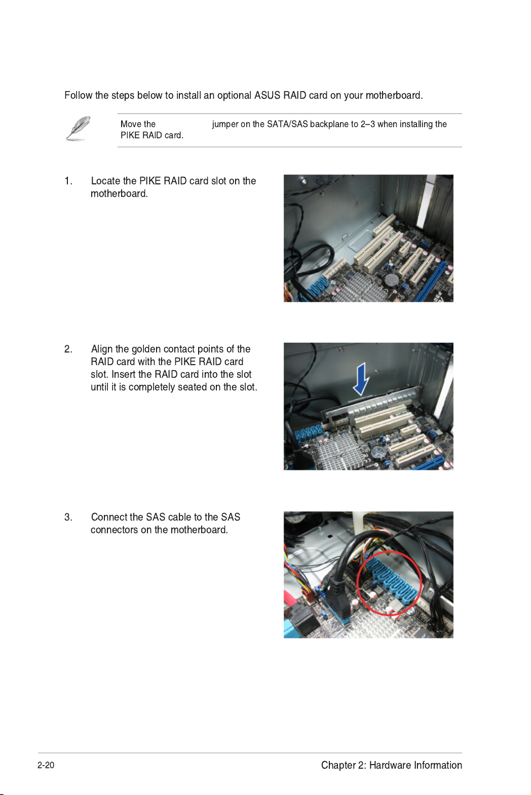
2.7.2 Installing an ASUS PIKE RAID card
SGPIO_SEL1

2.7.3 Installing ASMB7 management board

Chapter 2: Hardware Information
2-22
2.7.4 Configuring an expansion card
Afterinstallingtheexpansioncard,congureitbyadjustingthesoftwaresettings.
1. TurnonthesystemandchangethenecessaryBIOSsettings,ifany.SeeChapter5for
informationonBIOSsetup.
2. AssignanIRQtothecard.Refertothefollowingtables.
3. Installthesoftwaredriversfortheexpansioncard.
Standard Interrupt assignments
IRQ Priority Standard function
0 1 System Timer
1 2 KeyboardController
2 - ProgrammableInterrupt
3* 11 CommunicationsPort(COM2)
4* 12 CommunicationsPort(COM1)
5* 13 --
6 14 FloppyDiskController
7* --15
8 3 SystemCMOS/RealTimeClock
9* 4 ACPIModewhenused
10* 5 IRQHolderforPCISteering
11* 6 IRQHolderforPCISteering
12* 7 PS/2CompatibleMousePort
13 8 Numeric Data Processor
14* 9 PrimaryIDEChannel
15* 10 SecondaryIDEChannel
* These IRQs are usually available for ISA or PCI devices.
2-23
ASUS TS300-E8-PS4
2.8 Cable connections
• Thebundledsystemcablesarepre-connectedbeforeshipment.Youdonotneedto
disconnectthesecablesunlessyouwillremovepre-installedcomponentstoinstall
additional devices.
• RefertoChapter4fordetailedinformationontheconnectors.
2.8.1 Motherboard connections
Standard cables connected to the motherboard
1. 24-pinEATXpowerconnector(frompowersupplytomotherboard)
2. 8-pin12Vpowerconnector(frompowersupplytomotherboard)
3. Systemfanconnector(fromsystemfantomotherboard)
4. SATAconnectors(systemdefault:frommotherboardtoSATA/SASbackplane)
5. USB3.0connector(frommotherboardtofrontI/Oboard)
6. USB2.0connector(frommotherboardtofrontI/Oboard)
7. ChassisIntrusionconnector(fromrearchassisintrusionswitchtomotherboard)
8. Systempanelconnector(frommotherboardtofrontI/Oboard)
9. SASconnectors(forASUSPIKEonly;frommotherboardtoSATA/SASbackplane)
10. SerialGeneralPurposeInput/Outputconnectors

Chapter 2: Hardware Information
2-24
2.8.2 SATA/SAS backplane connections
ASATA/SASbackplanecomespre-installedintheTS300-E8.TheSATA/SASbackplane
hasfour22-pinSATA/SASconnectorstosupportSerialATAharddiskdrivesandSAShard
diskdrives.Thebackplanedesignincorporatesahotswapfeaturetoalloweasyinstallation
orremovalofSATA/SASharddisks.TheLEDsonthebackplaneconnecttothefrontpanel
LEDstoindicateHDDstatus.Seesection 1.7 LED information for details.
Front side
ThefrontsideoftheSATA/SASbackplanefacesthefrontpanelwheninstalled.Thisside
includesfourSATA/SASconnectorsforthehot-swapdrivetrays.
EachSATA/SASconnectorislabeled(HDD1,
HDD2,HDD3,HDD4)soyoucaneasilydetermine
theircounterpartconnectorsatthebacksideofthe
backplane.Refertothetableforreference.
Drive status LEDs
HDD1
HDD2
HDD3
HDD4
HDD1
HDD Device Front side connector Back side connector
HDD 1 HDD1 CON1
HDD 2 HDD2 CON2
HDD 3 HDD3 CON3
HDD 4 HDD4 CON4

Back side
BPSMB1
Connectors Description
SGPIO1
SGPIO2
SGPIO3
BPSMB1
U1
BP_Connector
CON1-4
SGPIO1
SGPIO_SEL1
SGPIO2
SGPIO3
CON1
CON2
U1
BP_Connector
CON4
CON3
SGPIO_SEL1

Chapter 2: Hardware Information
2-26
2.9.1 System fan
2.9 Removable components
You may need to remove previously installed system components when installing or removing
system devices, or when you need to replace defective components. This section tells how to
remove the following components:
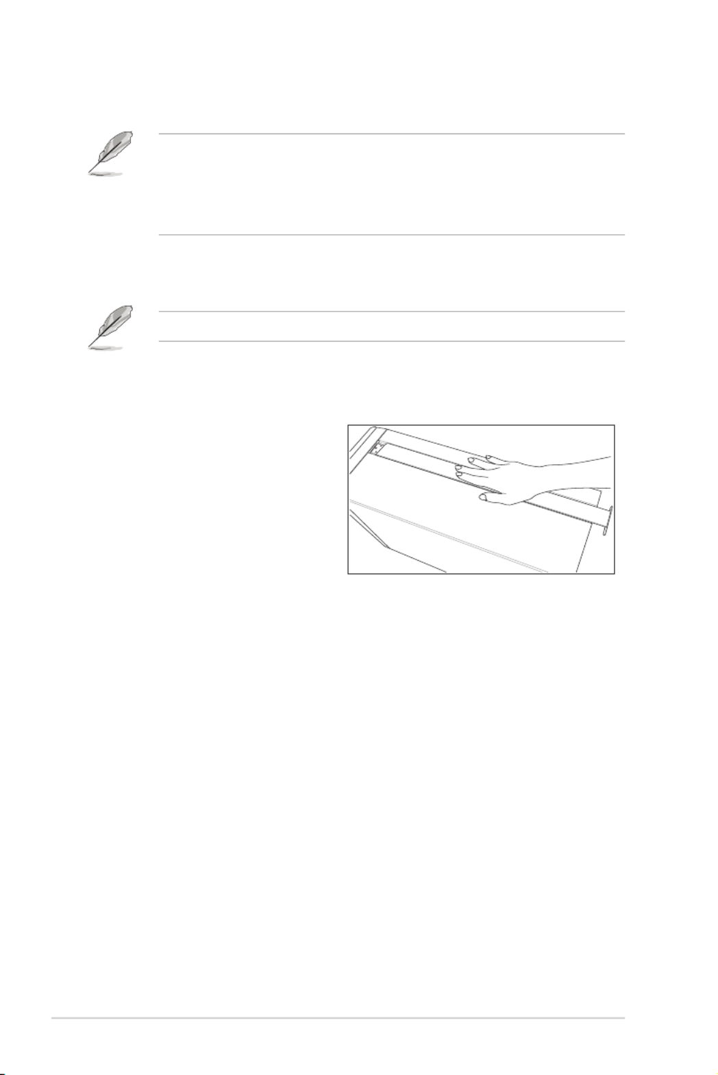
1. Rear system fan
2. Chassis footpads
To remove the rear system fan:
to release the system fan from its
position.
3. Remove the system fan.
reverse to reinstall the rear system fan.

2-27
ASUS TS300-E8-PS4
2.9.2 Chassis footpads
Thebareboneserversystemisshippedwithfourfootpadsattachedtothebottomofthe
chassisforstability.Youneedtoremovethesefootpadsifyouwishtoinstallthesystemtoa
rack.RefertoChapter3:InstallationOptionsofthisuserguide,andtothe“RackmountKit”
user guide for instructions.
To remove the footpads:
1. Lay the system chassis on its side.
2. Removethefootpadbyrotatingit
counterclockwisewithaPhillips(cross)
screwdriver.
3. Repeat step 1 and 2 to remove the
other three footpads.

Chapter 2: Hardware Information
2-28

This chapter describes how to install the optional components
and devices into the barebone server.
3
Installation Options
Chapter 3: Installation Options
Chapter 3: Installation Options
3-2
3.1.1 Removing the footpads
Refer to section 2.9.2 Chassis footpads for instructions on removing the footpads.
3.1 Preparing the system for rack mounting
• Theitemsrequiredfortheoptionalcongurationsdescribedinthischapterarenot
included in the standard barebone system package. These items are purchased
separately.
• Werecommendthatyouallotatleast1Uspaceabovetheserversystemtoensure
optimal thermal performance.
3.1.2 Removing the top cover
Unscrewandslidethetopcovertoward
the rear panel, and then lift it up from the
chassis.

3-3
ASUS TS300-E8-PS4
3.2 Attaching the inner rail to the server
3. Repeat the previous steps to secure
the other inner rail to the bottom of the
chassis with screws.
1. Slideouttheinnerrailfromthe
rackmount rail kit.
2. Align the screw holes on the inner rail
and the chassis top, and then secure
the inner rail to the chassis top with
screws.
4. Securetheraileartothetopand
the bottom of the chassis with three
screws respectively.

Chapter 3: Installation Options
3-4
1U space
2. Loosen the two screws on the rack
rails.
3.3 Attaching the rails to the rack
To attach the rails to the rack:
1. Selectoneunitofspace(1U)onthe
rack where you wish to install the
server.
5. Findtherear1Uspacethatcorrespondstothefront1Uspacewhereyouattachedthe
rail.
6. Drive in two screws on the outer holes to secure the rear end.
7. Fromtherackfront,ndthecorresponding1Uspaceforthesecondrailpair.
8. Repeat steps 3–6 to attach the second rail pair.
3. Align the front end holes of a rack
railpairtothe1Uspace.
4. Drive in two screws on the outer
holes to secure the front end.

3-5
ASUS TS300-E8-PS4
3.4 Mounting the server to the rack
2. Push the server all the way into the
rack.
To mount the server to the rack:
1. Aligntheserverrailswiththerack
rails.
3. Securetheservertotherack.

Chapter 3: Installation Options
3-6

This chapter includes the motherboard layout and brief
descriptions of the jumpers and internal connectors.
4
Motherboard Information
Chapter 4: Motherboard Information

Chapter 4: Motherboard Information
4-2
4.1 Motherboard overview
Before you install the motherboard, study the conguration of your chassis to ensure that the
motherboard ts into it.
To optimize the motherboard features, we highly recommend that you install it in an ATX 1.1
compliant chassis.
4.1.1 Placement direction
When installing the motherboard, ensure that you place it into the chassis in the correct
orientation. The edge with external ports goes to the rear part of the chassis as indicated in
the image below.
4.1.2 Screw holes
Place nine (9) screws into the holes indicated by circles to secure the motherboard to the
chassis.
DO NOT overtighten the screws! Doing so can damage the motherboard.
Ensure to unplug the chassis power cord before installing or removing the motherboard.
Failure to do so can cause you physical injury and damage motherboard components!
Place this side towards
the rear of the chassis

ASUS TS300-E8-PS4 4-3
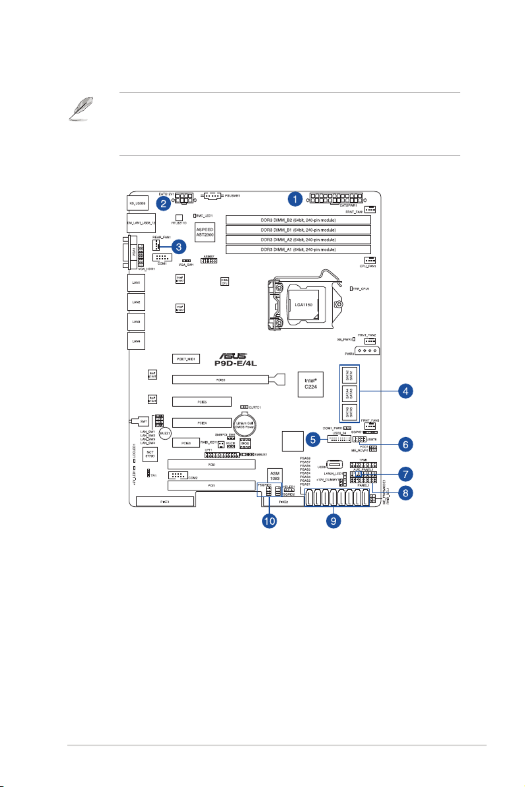
4.1.3 Motherboard layout

Chapter 4: Motherboard Information
4-4
Layout contents
Jumpers Page
1. Clear RTC RAM (3-pin CLRTC1) 4-11
2. VGA controller setting (3-pin VGA_SW1) 4-12
3. LAN controller setting (3-pin LAN_SW1-4) 4-12
4. RAID conguration utility selection (3-pin RAID_SEL1) 4-13
5. Platform Environmental Control Interface (PECI) Setting (3-pin PECI1) 4-13
6. LAN34_LED connector (5-1 pin LAN34_LED1) 4-14
7. Parallel port connector (26-1 pin LPT1) 4-14
8. VGA connector (16-1 pin VGA_HDR1) 4-15
Slots/Sockets Page
1. PCI Express x16 / PCI Express x8 / PCI Express p58-x1 / PCI slot 4-6
2. PIKE slot 4-7
Onboard LEDs Page
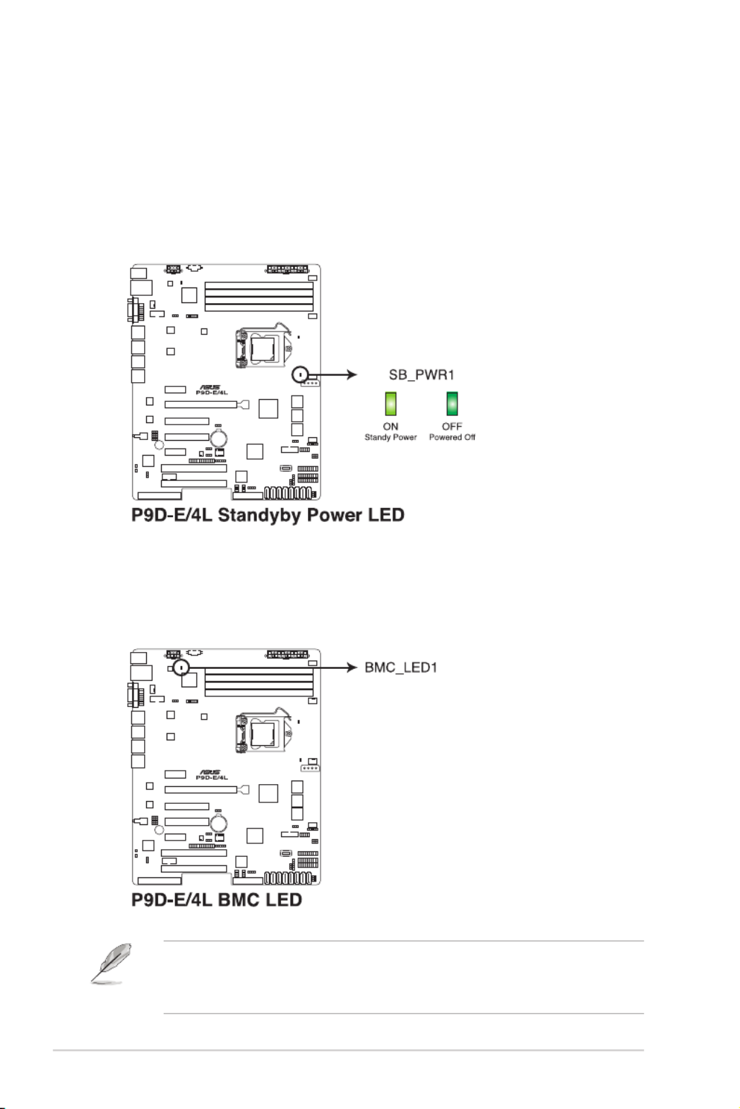
1. Standby Power LED (SB_PWR1) 4-8
2. Baseboard Management Controller LED (BMC_LED1) 4-8
3. CPU Warning LED (ERR_CPU1) 4-9
4. Power LED (+5V_LED) 4-9
5. Location LED (LOC_LED1) 4-10

ASUS TS300-E8-PS4 4-5
Internal connectors Page
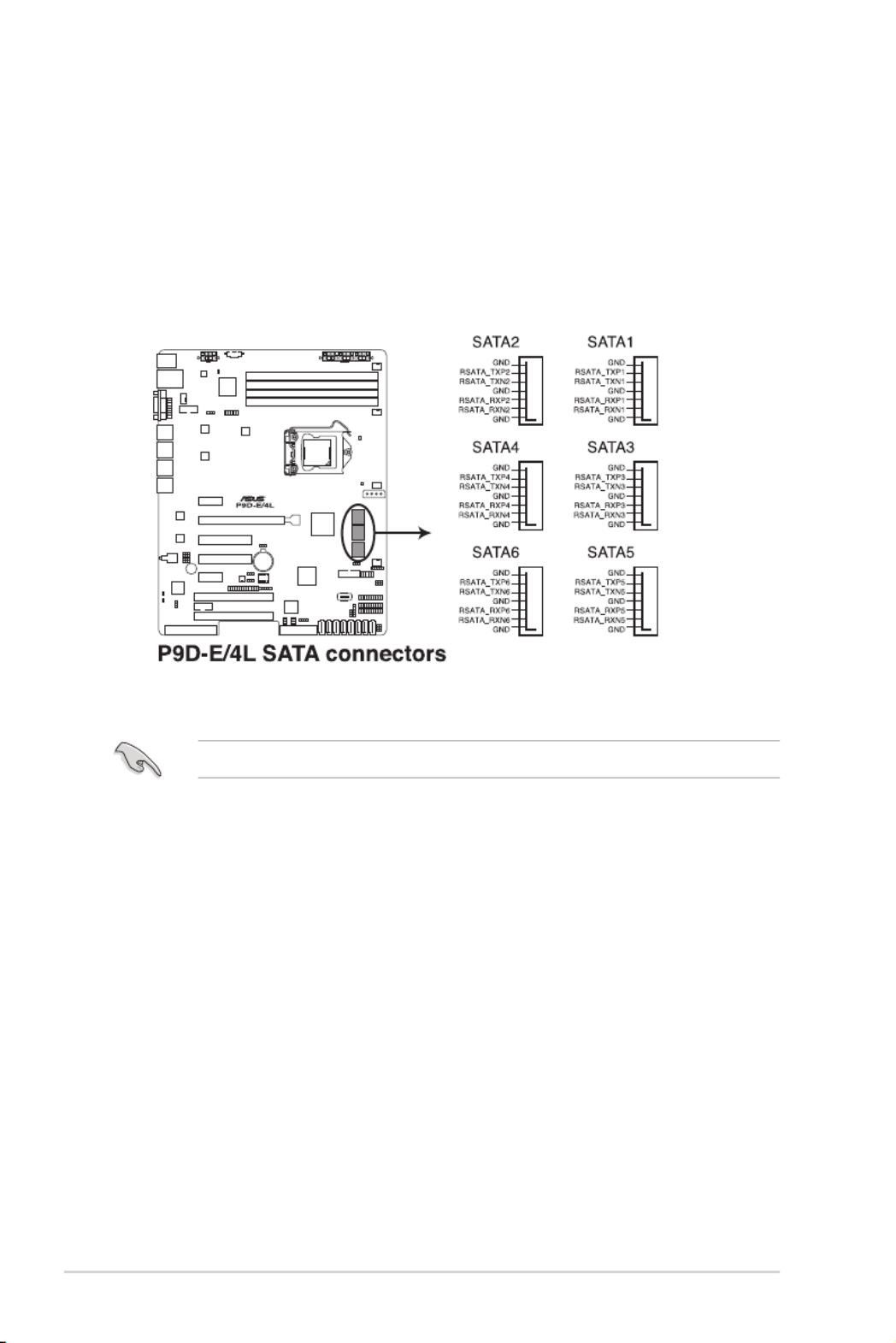
1. Serial ATA 6.0/3.0 Gbps connectors (7-pin 6Gbps SATA1-4 [Light Blue];
7-pin 3Gbps SATA5-6 [Black]) 4-16
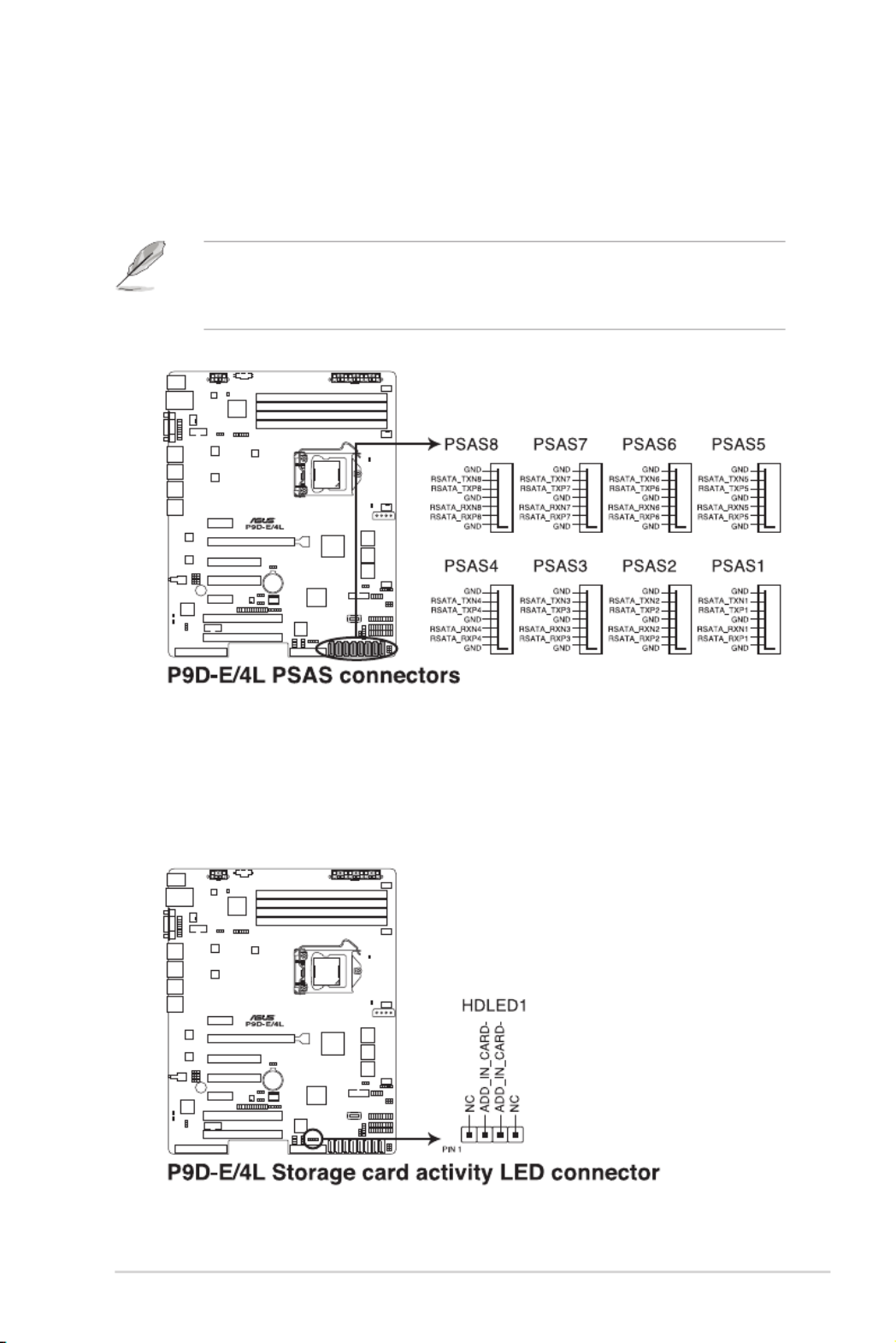
2. PSAS connectors (7-pin PSAS1-8 [Blue]) 4-17
3. Hard disk activity LED connector (4-pin HDLED1) 4-17
4. USB 2.0 connector (10-1 pin USB78; A-Type USB9) 4-18
5. USB 3.0 connector (20-1 pin USB3_34) 4-18
6. Thermal sensor cable connectors (3-pin TR1) 4-19
7. CPU, front, and rear fan connectors (4-pin CPU_FAN1, FRNT_FAN1-3,
REAR_FAN1) 4-19
8. Serial General Purpose Input/Output connector (6-1 pin SGPIO1)
PIKE Serial General Purpose Input/Output connectors
(8-1 pin PSGPIO1/2)
4-20
9. Serial port connectors (10-1 pin COM1/COM2) 4-21
10. Power Supply SMBus connector (5-pin PSUSMB1) 4-21
11. Trusted Platform Module connector (20-1 pin TPM1) 4-22
12. SATA DOM power connector (4-pin PWR3) 4-22
13. ATX power connectors (24-pin EATXPWR1, 8-pin EATX12V1) 4-23
14. System panel connector (20-1 pin PANEL1) 4-24
15. Auxiliary panel connector (20-2 pin AUX_PANEL1) 4-25

Chapter 4: Motherboard Information
4-6
4.2 Expansion slots
In the future, you may need to install expansion cards. The following subsections describe the
slots and the expansion cards that they support.
Ensure to unplug the power cord before adding or removing expansion cards. Failure to do
so may cause you physical injury and damage motherboard components.
4.2.1 PCI Express x16 slot (x16 link)
The onboard PCIE6 slot provides one x16 Gen3 link and auto switches to x8 link if PCIE5 is
occupied. This slot supports VGA cards and various server class high performance add-on
cards.
4.2.2 PCI Express x8 slot (x8 link)
The onboard PCIE 4 and PCIE 5 provide one x8 Gen3 link. These slots support VGA cards
and various server class high performance add-on cards.
4.2.3 PCI Express p60-x1 slot (x1 link)
The onboard PCIE 3 and PCIE 7 provide one p60-x1 Gen2 link to the Intel ® C224 PCH.
4.2.4 PCI slot
The PCI 1 and PCI 2 slots supports cards such as LAN, USB, and other cards that complies
with PCI specications.

ASUS TS300-E8-PS4 4-7
4.2.5 PIKE slot
The PIKE slots allows you to choose and change your preferred SAS solution easily. Install
an optional ASUS PIKE RAID card based on your needs.
No.(Slot location) Short Description
1 (slot 1) PCI1 PCI 32 bit / 33 MHz
2 (slot 2) PCI2 PCI 32 bit / 33 MHz
3 (slot 3) PCIE3 PCI-E p61-x1 (x1 Gen2 link)
4 (slot 4) PCIE4 PCI-E x8 (x8 Gen3 link)
5 (slot 5) PCIE5 PCI-E x8 (x8 Gen3 link)
6 (slot 6) PCIE6 PCI-E x16 (x16 Gen3 link)
(Auto switch to x8 if slot 5 is occupied)
7 (slot 7) PCIE7 PCI-E p61-x1 (x1 Gen2 link); MIO-892 Supported
Chapter 4: Motherboard Information
4-8
2. Baseboard Management Controller LED (BMC_LED1)
The green heartbeat LED blinks per second to indicate that the ASMB7 is working
normally.
• The heartbeat LED functions only when you install the ASUS ASMB7.
• Everytime after the AC power is replugged, you have to wait for about 60 seconds for
the system to power up.
4.3 Onboard LEDs
1. Standby Power LED (SB_PWR1)
The motherboard comes with a standby power LED. The green LED lights up to
indicate that the system is ON, in sleep mode, or in soft-off mode. This is a reminder
that you should shut down the system and unplug the power cable before removing or
plugging in any motherboard component. The illustration below shows the location of
the onboard LED.

ASUS TS300-E8-PS4 4-9
3. CPU Warning LED (ERR_CPU1)
The CPU warning LED lights up to indicate that a CPU error or failure has occurred.
4. Power LED (+5V_LED1)
This LED lights up when the Power-on button is pressed and the system is on.
The warning LED functions only when you install the ASUS ASMB7 Management card.

Chapter 4: Motherboard Information
4-10
5. Location LED (LOCLED1)
The Location LED ligths up when the Location Button on the front panel is pressed.
This onboard LED functions like the Locator LED on the front and is useful in nding a
specic server module within a chassis.

ASUS TS300-E8-PS4 4-11
4.4 Jumpers
1. Clear RTC RAM (3-pin CLRTC1)
This jumper allows you to clear the Real Time Clock (RTC) RAM in CMOS. You can
clear the CMOS memory of date, time, and system setup parameters by erasing the
CMOS RTC RAM data. The onboard button cell battery powers the RAM data in CMOS
which include system setup information such as system passwords.
To erase the RTC RAM:
1. Turn OFF the computer and unplug the power cord.
2. Move the jumper cap from the default pins 1–2 to pins 2–3. Keep the cap on pins
2–3 for about 5 to 10 seconds, then move the cap back to pins 1–2.
3. Plug the power cord and turn ON the computer.
4. Hold down the <Del> key during the boot process and enter BIOS setup to re-
enter data.
DO NOT remove the cap on CLRTC jumper default position except when clearing the RTC
RAM. Removing the cap will cause system boot failure!
If the steps above do not help, remove the onboard battery and move the jumper again to
clear the CMOS RTC RAM data. After the CMOS clearance, reinstall the battery.

Chapter 4: Motherboard Information
4-12
2. VGA controller setting (3-pin VGA_SW1)
This jumper allows you to enable or disable the onboard VGA controller. Set to pins 1–2
to activate the VGA feature.
3. LAN controller setting (3-pin LAN_SW1-4)
These jumpers allow you to enable or disable the onboard Intel ® I210AT Gigabit LAN
controllers. Set to pins 1–2 to activate the Gigabit LAN feature.

ASUS TS300-E8-PS4 4-13
4. RAID configuration utility selection (3-pin RAID_SEL1)
This jumper allows you to select the RAID conguration utility to use when you create
disk arrays. Place the jumper caps over pins 1–2 if you want to use the third party
software RAID Utility; otherwise, place the jumper caps to pins 2–3 to use the Intel ®
Rapid Storage Technology enterprise SATA Option ROM Utility.
5. Platform Enviromental Control Interface Setting (3-pin PECI1)
When an ASMB7-iKVM is installed, set these to pins 2–3 for correct sensor information
of the Platform Environmental Control Interface (PECI). Set to pins 1–2 if ASMB7-iKVM
is not installed.

Chapter 4: Motherboard Information
4-14
6. LAN34_LED connector (5-1 pin LAN34_LED1)
These leads are for Gigabit LAN activity LEDs on the front panel. Connect the LAN
LED cable to the backplane for LAN activity indication.
7. Parallel port connector (26-1 pin LPT1)
This connector is for the parallel port. Connect the parallel port module cable to this
connector, then install the module to a slot opening at the back of the system chassis.

ASUS TS300-E8-PS4 4-15
8. VGA connector (16-1 pin VGA_HDR1)
This connector supports the VGA High Dynamic-Range interface.
Chapter 4: Motherboard Information
4-16
The actual data transfer rate depends on the speed of Serial ATA hard disks installed.
4.5 Internal connectors
1. Serial ATA 6.0/3.0 Gbps connectors
(7-pin 6Gbps SATA1-4 [Light Blue]; 7-pin 3Gbps SATA5-6 [Black])
Supported by the Intel ® C224 chipset, these connectors are for the Serial ATA signal
cables for Serial ATA hard disk drives that allows up to 6Gbps of data transfer rate.
If you installed Serial ATA hard disk drives, you can create a RAID 0, RAID 1, RAID 10,
or RAID 5 conguration.
ASUS TS300-E8-PS4 4-17
3. Hard disk activity LED connector (4-pin HDLED1)
This LED connector is for the storage add-on card cable connected to the SATA or
SAS add-on card. The read or write activities of any device connected to the SATA or
SAS add-on card causes the front panel LED to light up.
2. PSAS connectors (7-pin PSAS1-8 [Blue])
This motherboard comes with eight (8) PIKE Serial Attached SCSI (PSAS) connectors
that supports both Serial Attached SCSI (SAS) and Serial ATA (SATA). Each connector
supports one device.
• These connectors function only when you install a PIKE RAID card.
• Connect the SAS hard disk drives to PSAS connectors 1–8 (blue) when installing a
4-port PIKE RAID card.

Chapter 4: Motherboard Information
4-18
4. USB 2.0 connectors (10-1 pin USB78; A-Type USB9)
These connectors are for USB 2.0 ports. Connect the USB module cables to
connectors USB78, then install the modules to a slot opening at the back of the system
chassis. These USB connectors comply with USB 2.0 specication that supports up to
480 Mbps connection speed.
5. USB 3.0 connector (20-1 pin USB3_34)
These connectors are for USB 3.0 ports. These USB connectors comply with USB 3.0
specication that supports up to 5 Gbps connection speed.
The USB 3.0 ports are backward compatible with USB 2.0 and also supports fast-charging
of supported devices.

ASUS TS300-E8-PS4 4-19
7. CPU, front, and rear fan connectors
(4-pin CPU_FAN1, FRNT_FAN1-3, REAR_FAN1)
The fan connectors support cooling fans. Connect the fan cables to the fan connectors
on the motherboard, ensuring that the black wire of each cable matches the ground pin
of the connector.
• DO NOT forget to connect the fan cables to the fan connectors. Insufcient air ow
inside the system may damage the motherboard components.
• These are not jumpers! DO NOT place jumper caps on the fan connectors!
• All fans feature the ASUS Smart Fan technology.
6. Thermal sensor cable connectors (3-pin TR1)
This connector is for temperature monitoring. Connect the thermal sensor cable
to this connector and place the other end to the device, which you want to monitor
temperature.

Chapter 4: Motherboard Information
4-20
8. Serial General Purpose Input/Output connector (6-1 pin SGPIO1)
The SGPIO 1 connectors are used for the Intel Rapid Storage Technology Enterprise
SGPIO interface that controls the LED pattern generation, device information, and
general purpose data.
The PSGPIO 1/2 connectors are used for PIKE card.
These connectors function only when you install an ASUS PIKE SAS RAID card.

ASUS TS300-E8-PS4 4-21
9. Serial port connectors (10-1 pin COM1/COM2)
These connectors are for the serial COM ports. Connect the serial port module cable
to one of these connectors, then install the module to a slot opening at the back of the
system chassis.
10. Power Supply SMBus connector (5-pin PSUSMB1)
This connector allows you to connect SMBus (System Management Bus) to the power
supply unit to read PSU information. Devices communicate with an SMBus host and/or
other SMBus devices using the SMBus interface.
This connector functions only when you install the ASUS ASMB7.

Chapter 4: Motherboard Information
4-22
11. Trusted Platform Module connector (20-1 pin TPM1)
This connector supports a Trusted Platform Module (TPM) system, which can securely
store keys, digital certicates, passwords, and data. A TPM system also helps enhance
network security, protects digital identities, and ensures platform integrity.
12. SATA DOM power connector (4-pin PWR3)
This 4-pin connector is for 5V power of a certain SATA DOM (Disk on Module) device
when using an appropriate cable.
• The SATA DOM power connector is for output power only. It has a maximum output
current of 1A.
• Ensure that the power of the SATA DOM device that you will use is less than 1A.

ASUS TS300-E8-PS4 4-23
13. ATX power connectors (24-pin EATXPWR1, 8-pin EATX12V1)
These connectors are for the ATX power supply plugs. The power supply plugs are
designed to t these connectors in only one orientation. Find the proper orientation and
push down rmly until the connectors completely t.
• DO NOT forget to connect the 24-pin and the 8-pin power plugs; otherwise, the system
will not boot up.
• Use of a power supply unit (PSU) with a higher power output is recommended when
conguring a system with more power-consuming devices. The system may become
unstable or may not boot up if the power is inadequate.
• This motherboard supports ATX2.0 PSU or later version.
• Ensure that your PSU can provide at least the minimum power required by your
system.

Chapter 4: Motherboard Information
4-24
14. System panel connector (20-1 pin PANEL1)
This connector supports several chassis-mounted functions.
1. System power LED (3-pin PLED)
This 3-pin connector is for the system power LED. Connect the chassis power
LED cable to this connector. The system power LED lights up when you turn on
the system power, and blinks when the system is in sleep mode.
2. Message LED (2-pin MLED)
This 2-pin connector is for the message LED cable that connects to the front
message LED. The message LED is controlled by Hardware monitor to indicate
an abnormal event occurance.
3. System warning speaker (4-pin SPEAKER)
This 4-pin connector is for the chassis-mounted system warning speaker. The
speaker allows you to hear system beeps and warnings.
4. Hard disk drive activity LED (2-pin +HDLED)
This 2-pin connector is for the HDD Activity LED. Connect the HDD Activity LED
cable to this connector. The IDE LED lights up or ashes when data is read from
or written to the HDD.
5. Power button/soft-off button (2-pin PWRSW)
This connector is for the system power button. Pressing the power button turns
the system on or puts the system in sleep or soft-off mode depending on the BIOS
settings. Pressing the power switch for more than four seconds while the system
is ON turns the system OFF.
6. Reset button (2-pin RESET)
This 2-pin connector is for the chassis-mounted reset button for system reboot
without turning off the system power.

ASUS TS300-E8-PS4 4-25
15. Auxiliary panel connector (20-2 pin AUX_PANEL1)
This connector is for additional front panel features including front panel SMB, locator
LED and switch, chassis intrusion, and LAN LEDs.
1. Front panel SMB (6-1 pin FPSMB)
These leads connect the front panel SMBus cable.
2. LAN activity LED (2-pin LAN1_LINKACTLED, LAN2_LINKACTLED)
These leads are for Gigabit LAN activity LEDs on the front panel.
3. Chassis intrusion (4-1 pin CASEOPEN)
These leads are for the intrusion detection feature for chassis with intrusion
sensor or microswitch. When you remove any chassis component, the sensor
triggers and sends a high-level signal to these leads to record a chassis intrusion
event. The default setting is short CASEOPEN and GND pin by jumper cap to
disable the function.
4. Locator LED (2-pin LOCATORLED1, LOCATORLED2)
These leads are for the locator LED1 and LED2 on the front panel. Connect the
Locator LED cables to these 2-pin connector. The LEDs will light up when the
Locator button is pressed.
5. Locator Button/Switch (2-pin LOCATORBTN#)
These leads are for the locator button on the front panel. This button queries the
state of the system locator.

Chapter 4: Motherboard Information
4-26

5
BIOS Setup
This chapter tells how to change the system settings through
the BIOS Setup menus. Detailed descriptions of the BIOS
parameters are also provided.
Chapter 5: BIOS Setup

5-2 Chapter 5: BIOS Setup
5.1 Managing and updating your BIOS
The following utilities allow you to manage and update the motherboard Basic Input/Output
System (BIOS) setup:
1. ASUS CrashFree BIOS 3
TorecovertheBIOSusingabootableUSBashdiskdrivewhentheBIOSlefailsor
gets corrupted.
2. ASUS EzFlash
UpdatestheBIOSusingaUSBashdisk.
3. BUPDATER
UpdatestheBIOSinDOSmodeusingabootableUSBashdiskdrive.
Refer to the corresponding sections for details on these utilities.
Recovering the BIOS from a USB flash drive
TorecovertheBIOSfromaUSBashdrive:
1. InserttheUSBashdrivewiththeoriginalorupdatedBIOSletooneUSBportonthe
system.
2. The utility will automatically recover the BIOS. It resets the system when the BIOS
recoveryisnished.
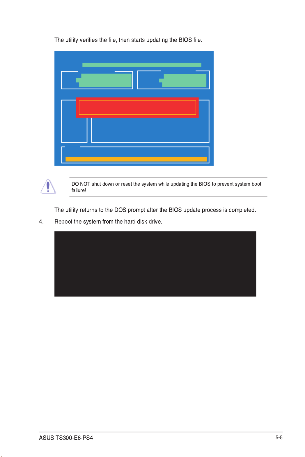
DO NOT shut down or reset the system while recovering the BIOS! Doing so would cause
system boot failure!
The recovered BIOS may not be the latest BIOS version for this motherboard. Visit the
ASUSwebsiteatwww.asus.comtodownloadthelatestBIOSle.
SaveacopyoftheoriginalmotherboardBIOSletoabootableUSBashdiskdrivein
case you need to restore the BIOS in the future. Copy the original motherboard BIOS using
the BUPDATER utility.
5.1.1 ASUS CrashFree BIOS 3 utility
TheASUSCrashFreeBIOS3isanautorecoverytoolthatallowsyoutorestoretheBIOSle
when it fails or gets corrupted during the updating process. You can update a corrupted BIOS
leusingaUSBashdrivethatcontainstheupdatedBIOSle.
PrepareaUSBashdrivecontainingtheupdatedmotherboardBIOSbeforeusingthis
utility.

5-3
3. Press <Tab> to switch to the Drive
then press <Enter>.
5. Press <Tab> to switch to the Folder Info
7. Reboot the system when the update process is done.
5.1.2 ASUS EzFlash Utility
The ASUS EzFlash Utility feature allows you to update the BIOS without having to use a
DOS-based utility.
The succeeding BIOS screens are for reference only. The actual BIOS screen displays may
not be the same as shown.
To update the BIOS using EzFlash Utility:
2. Enter the BIOS setup program. Go to the menu to select Tool ASUS EzFlash Utility
and press <Enter> to enable it.
Download the latest BIOS from the ASUS website at www.asus.com before using this
utility.
ASUS Tek. EzFlash Utility
[Up/Down/Left/Right]:Switch [Enter]:Choose [q]:Exit
FS0 System Volume Information <DIR>
P9D-X Bios <DIR>
Windows <DIR>
P9D-E/4L Bios
Current Platform
Platform : P9D-E/4L
Version : 0051
Build Date :11/26/2012
New Platform
Platform : P9D-E/4L
Version : 0060
Build Date :12/03/2012
<DIR>
single partition only.
boot failure!
Ensure to load the BIOS default settings to ensure system compatibility and stability. Press
<F5> and select to load the BIOS default settings.Yes

5.1.3 BUPDATER utility
Updating the BIOS file
BUPDATER /i[lename].ROM
A:\>BUPDATER /i[le name].ROM
The BIOS update is nished! Please restart your system.
C:\>
ASUSTek BIOS Update for DOS V1.06 (09/08/04)
Current ROM Update ROM
Note
Writing BIOS:
FLASH TYPE: MXIC 25L1605A
PATH:
BOARD: P9D-E/4L
VER: 0201
DATE: 12/01/2012
BOARD: P9D-E/4L
VER: 0202
DATE: 12/09/2012
WARNING! Do not turn off power during ash BIOS

5.2 BIOS setup program
Yes
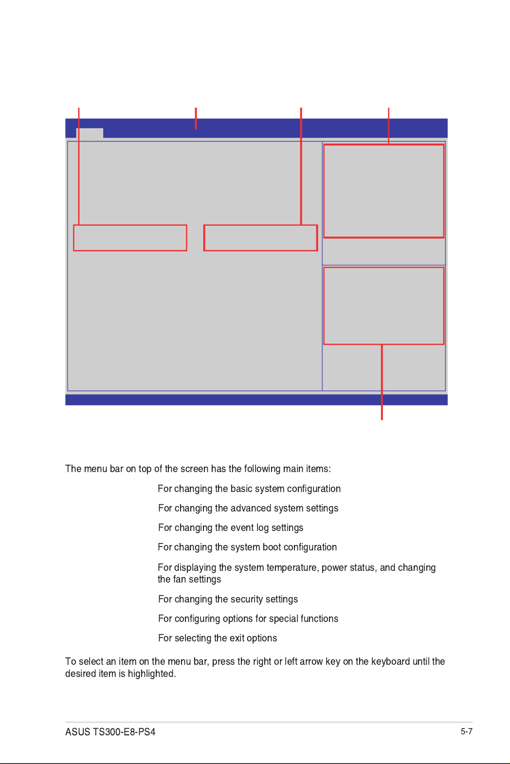
5.2.2 Menu bar
Main
Advanced
Event Logs
Boot
Monitor
Security
Tool
Exit
5.2.1 BIOS menu screen
Version 2.15.1236. Copyright (C) 2013 American Megatrends, Inc.
Aptio Setup Utility - Copyright (C) 2013 American Megatrends, Inc.
Main Advanced Event Logs Boot Monitor Security Tool Exit
Set the Date, Use Tab to
switch between Data elements.
→←: Select Screen
↑↓: Select Item
Enter: Select Item
+/-: Change Opt.
F1: General Help
F2: Previous Values
F5: Optimized Defaults
F10: Save & Exit
ESC: Exit
BIOS Information
BIOS Vendor American Megatrends
BIOS Version 4.6.5.4
Compliancy UEFI 2.3.1; PI 1.2
BIOS Version 0077 x64
Build Date 01/31/2013
System Date [Mon 02/21/2013]
System Time [10:10:10]
Navigation keys
General helpMenu bar Configuration fieldsMenu items
5.2.3 Menu items
Main
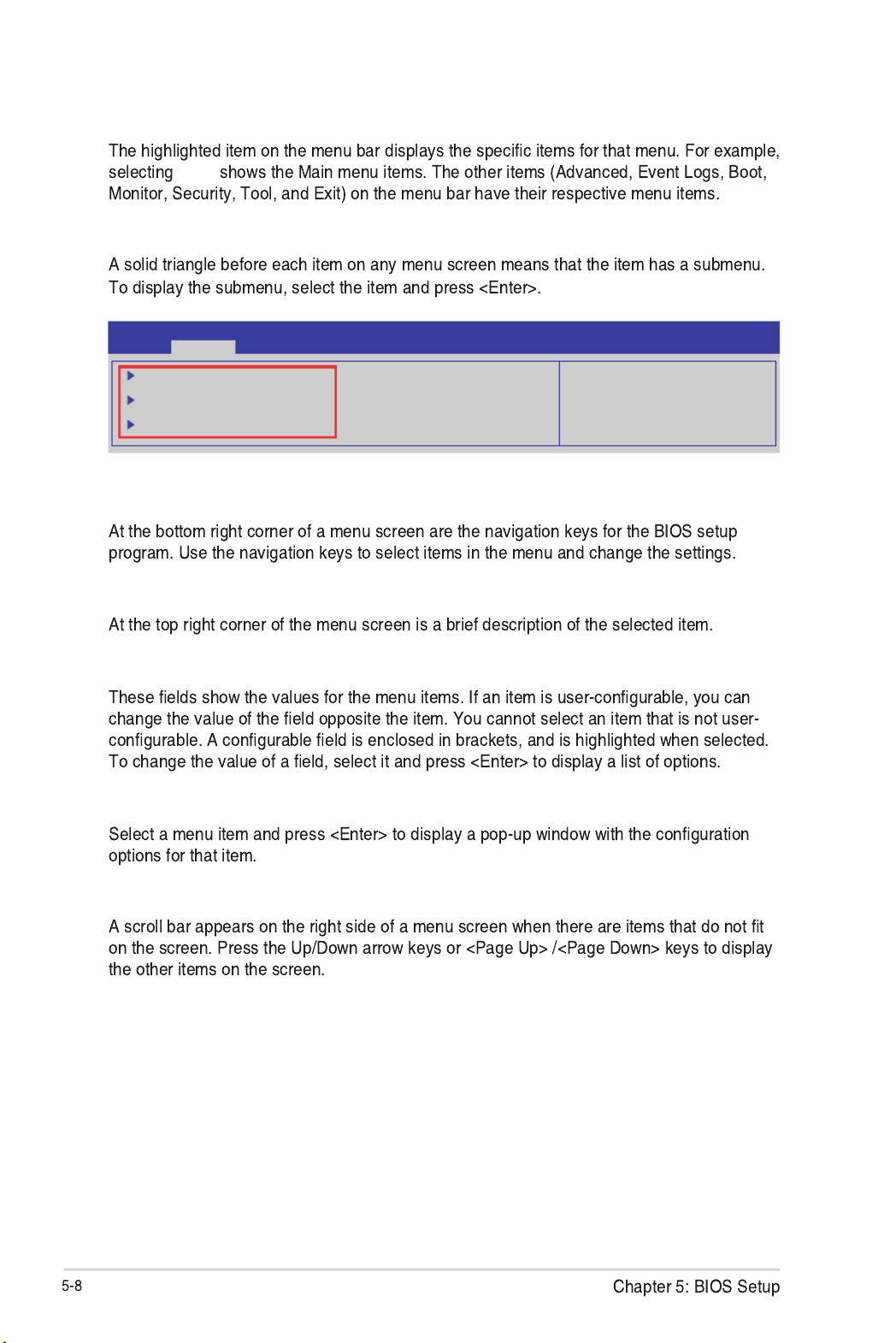
5.2.4 Submenu items
PCI, PCI-X and PCI Express
Settings.
Aptio Setup Utility - Copyright (C) 2013 American Megatrends, Inc.
Main Event Logs Boot Monitor Security Tool ExitAdvanced
PCI, PCI-X and PCI Express
Settings.
PCI Subsystem Settings
ACPI Settings
Trusted Computing
5.2.5 Navigation keys
5.2.6 General help
5.2.7 Configuration fields
5.2.8 Pop-up window
5.2.9 Scroll bar

5.3 Main menu
5.3.1 System Date
[Day mm/dd/yyyy]
5.3.2 System Time
[hh/mm/ss]
Aptio Setup Utility - Copyright (C) 2013 American Megatrends, Inc.
Main Advanced Event Logs Boot Monitor Security Tool Exit
Set the Date, Use Tab to
switch between Data elements.
BIOS InformationBIOS Vendor American Megatrends
BIOS Version 4.6.5.4
Compliancy UEFI 2.3.1; PI 1.2
BIOS Version 0077 x64
Build Date 01/31/2013
System Date [Mon 02/22/2013]
System Time [10:10:10]

5.4 Advanced menu
Aptio Setup Utility - Copyright (C) 2014 American Megatrends, Inc.
Aptio Setup Utility - Copyright (C) 2013 American Megatrends, Inc.
Main Event Logs Boot Monitor Security Tool ExitAdvanced
PCI, PCI-X and PCI
Express Settings.
CPU Conguration
PCH-IO Conguration
SATA Conguration
Systems Agent (SA) Conguration
PCI Subsystem Settings
USB Conguration
TPM
ACPI Settings
WHEA Conguration
NCT6779D Super IO Conguration
Intel Server Platform Services
Onboard LAN Conguration
MIO Card Conguration
Serial Port Console Redirection
Runtime Error Logging
APM
Network Stack
Intel RC Drivers Version Detail

5.4.1 CPU Configuration
Page Down
Page Up
Aptio Setup Utility - Copyright (C) 2013 American Megatrends, Inc.
Advanced
CPU Conguration
Genuine Intel (R) CPU 0000 @ 2.50GHz
CPU Signature 306c2
Microcode Patch ffff0006
Max CPU Speed 2500 MHz
Min CPU Speed 800 MHz
CPU Speed 2500 MHz
Processor Cores 4
Intel HT Technology Supported
Intel VT-x Technology Supported
Intel SMX Technology Supported
64-bit Supported
EIST Technology Supported
CPU C3 State Supported
CPU C6 State Supported
CPU C7 State Supported
L1 Data Cache 32 kB x 4
L1 Code Cache 32 kB x 4
L2 Cache 256 kB x 4
L3 Cache 8192 kB
Version 2.15.1236. Copyright (C) 2013 American Megatrends, Inc.
→←: Select Screen
↑↓: Select Item
Enter: Select Item
+/-: Change Opt.
Enabled for WIndows XP and
Linux (OS optimized for Hyper-
Threading Technology) and
Disabled for other OS (OS not
optimized for Hyper-Threading
Technology). When Disabled only
one thread per enabled core is
enabled.
Aptio Setup Utility - Copyright (C) 2013 American Megatrends, Inc.
Advanced
Version 2.15.1236. Copyright (C) 2013 American Megatrends, Inc.
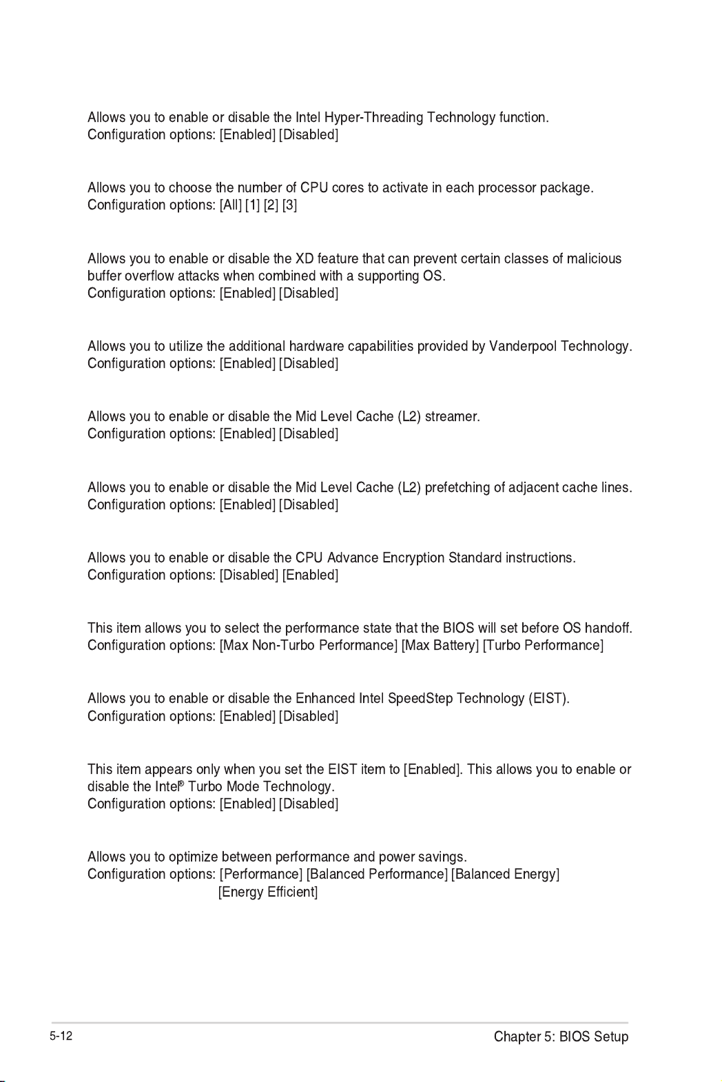
Hyper-threading [Enabled]
Active Processor Cores [All]
Execute Disable Bit [Enabled]
Inter Virtualization Technology[Enabled]
Hardware Prefetcher [Enabled]
Adjacent Cache Line Prefetch [Enabled]
CPU AES [Enabled]
Boot performance mode [Turbo Performance]
EIST [Enabled]
Turbo Mode [Enabled]
Energy Performance [Performance]
CPU C states [Enabled]
Enhanced C1 state [Enabled]
CPU C3 Report [Enabled]
CPU C6 report [Enabled]
CPU C7 report [CPU C7s]
C1 state auto demotion [Enabled]
C3 state auto demotion [Enabled]
Package C State limit [AUTO]
LakeTiny Feature [Disabled]
Intel TXT (LT) Support [Disabled]
ACPI T State [Disabled]
L2 Cache 2 5 6 k B x 4
L3 Cache 8192 kB
→←: Select Screen
↑↓: Select Item
Enter: Select Item
+/-: Change Opt.
F1: General Help
F2: Previous Values
F5: Optimized Defaults
F10: Save & Exit
ESC: Exit
Hyper-threading [Enabled]
Active Processor Cores [All]
Execute Disable Bit [Enabled]
Intel Virtualization Technology [Enabled]
Hardware Prefetcher [Enabled]
Adjacent Cache Line Prefetch [Enabled]
CPU AES [Enabled]
Boot performance mode [Turbo Performance]
EIST [Enabled]
Turbo Mode [Enabled]
Energy Performance [Performance]
Enhanced C1 State [Enabled]
CPU C3 Report [Enabled]
CPU C6 Report [Enabled]
CPU C7 Report [CPU C7s]
C1 state auto demotion [Enabled]
C3 state auto demotion [Enabled]
Package C State limit [AUTO]
LakeTiny Feature [Disabled]
Intel TXT (LT) Suppot [Disabled]
ACPI T State [Disabled]
CPU C states [Enabled]
CPU C states [Enabled]
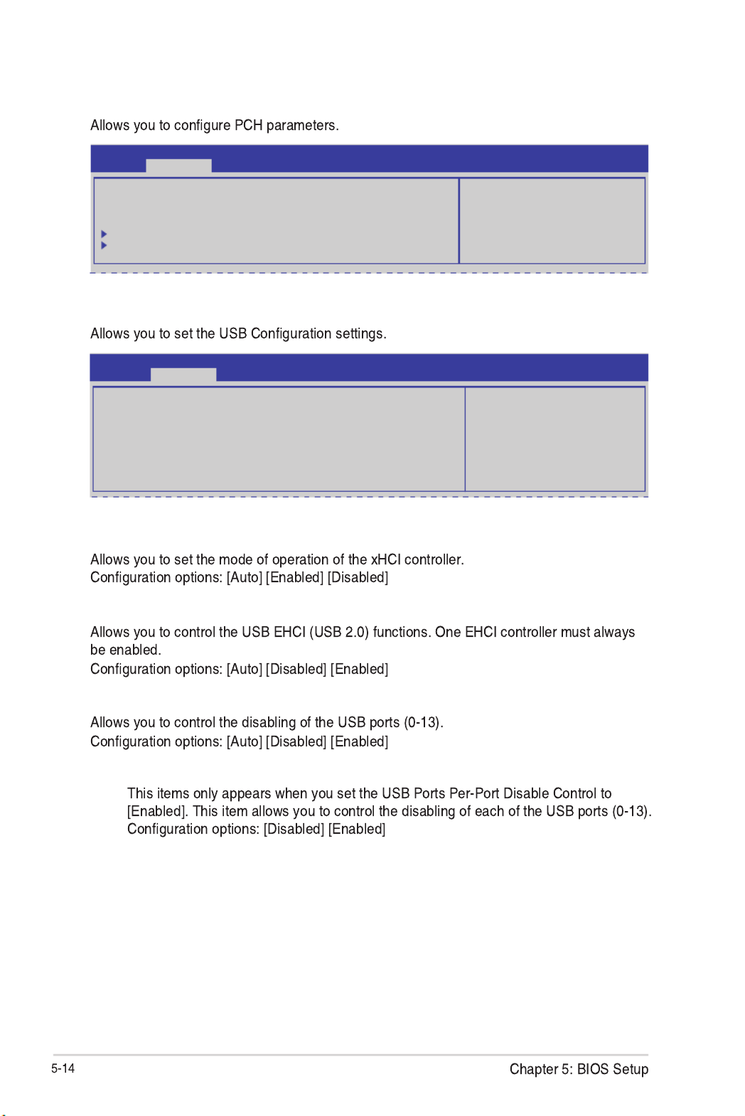
5.4.2 PCH-IO Configuration
Aptio Setup Utility - Copyright (C) 2013 American Megatrends, Inc.
Advanced
Intel PCH RC Version 1.0.0.0
Intel PCH SKU Name C224
Intel PCH Rev ID 04/C1
USB Conguration
PCH Azalia Conguration
USB Conguration
settings.
USB Configuration
Aptio Setup Utility - Copyright (C) 2013 American Megatrends, Inc.
Advanced
Mode of operation of xHCI
controller.
USB Conguration
XHCI Mode [Auto]
EHCI1 [Enabled]
EHCI2 [Enabled]
USB Ports Per-Port Disable Control [Disabled]
XHCI Mode [Auto]
EHCI1 / EHCI2 [Enabled]
USB Ports Per-Port Disable Control [Disabled]
USB Port #0-#13 Disable [Enabled]

5.4.3 SATA Configuration
Not Present
SATA Controller(s) [Enabled]
SATA Mode Selection [AHCI]
S.M.A.R.T. Status Check [Enabled]
Aptio Setup Utility - Copyright (C) 2013 American Megatrends, Inc.
Advanced
SATA Controller(s) [Enabled]
SATA Mode Selection [AHCI]
S.M.A.R.T. Status Check [Enabled]
Serial ATA Port 0 HardDisk (250.0GB)
Software Preserve SUPPORTED
Port 0 [Enabled]
Hot Plug [Enabled]
SATA Device Type [Hard Disk Drive]
Spin Up Device [Disabled]
Serial ATA Port 1 HardDisk (250.0GB)
Software Preserve SUPPORTED
Port 1 [Enabled]
Hot Plug [Enabled]
SATA Device Type [Hard Disk Driver]
Spin Up Device [Disabled]
Serial ATA Port 2 HardDisk (250.0GB)
Software Preserve SUPPORTED
Port 2 [Enabled]
Hot Plug [Enabled]
SATA Device Type [Hard Disk Driver]
Spin Up Device [Disabled]
Enable or disable SATA
Device.
Aptio Setup Utility - Copyright (C) 2013 American Megatrends, Inc.
Advanced
Control Detection of the
Azalia device. Disabled =
Azalia will be unconditionally
disabled Enabled = Azalia will
be unconditionally Enabled
Auto = Azalia will be
enabled if present, disabled
otherwise.
PCH Azalia Conguration
Azalia [Auto]
PCH Azalia Configuration

Compatible Mode [Disabled]
Aptio Setup Utility - Copyright (C) 2013 American Megatrends, Inc.
Advanced
SATA Controller(s) [Enabled]
SATA Mode Selection [IDE]
Compatible Mode [Disabled]
S.M.A.R.T. Status Check [Enabled]
Serial SATA Port 0 HardDisk (250.0GB)
Software Preserve SUPPORTED
Serial SATA Port 1 HardDisk (250.0GB)
Software Preserve SUPPORTED
Serial SATA Port 2 HardDisk (250.0GB)
Software Preserve SUPPORTED
Serial SATA Port 3 HardDisk (250.0GB)
Software Preserve SUPPORTED
Serial SATA Port 4 HardDisk (250.0GB)
Software Preserve SUPPORTED
Serial SATA Port 5 ASUS DVD-E8 ATAPI
Software Preserve SUPPORTED
Determines how SATA
controller(s) operate.
5.4.4 System Agent (SA) Configuration
Aptio Setup Utility - Copyright (C) 2013 American Megatrends, Inc.
Advanced
System Agent Bridge Name Haswell
System Agent RC Version 1.0.0.0
VT-d Capability Supported
VT-d [Enabled]
Enable NB Card [Disabled]
BDAT ACPI Table Support [Disabled]
VGA Priority [Offboard]
Memory Conguration
Check to enable VT-d
function on MCH.
VT-d [Enabled]
Enable NB Card [Disabled]
BDAT ACPI Table Support [Disabled]
VGA Priority [Offboard]

Memory Configuration
Memory Frequency Limiter [Auto]
ECC Support [Enabled]
Memory Scrambler [Enabled]
Memory Remap [Enabled]
GDXC Support [Disabled]
Memory Information
Memory RC Version 1.0.0.0
Memory Frequency 1067 MHz
Usage Memory 1024 MB (DDR3)
DIMM_A1 Not Present
DIMM_A2 1024 MB (DDR3)
DIMM_A3 Not Present
DIMM_A4 Not Present
CAS Latency (tCL) 7
Minimum delay time
CAS to RAS (tRCDmin) 7
Row Precharge (tRPmin) 7
Active to Precharge (tRASmin) 20
Memory Frequency Limiter [Auto]
ECC Support [Enabled]
Memory Scrambler [Enabled]
Memory Remap [Enabled]
GDXC Support [Disabled]
Maximum Memory Frequency
Selections in MHz.
Aptio Setup Utility - Copyright (C) 2013 American Megatrends, Inc.
Advanced

5.4.5 PCI Subsystem Settings
Above 4G Decoding [Disabled]
Load RT32 Image [Enabled]
Aptio Setup Utility - Copyright (C) 2013 American Megatrends, Inc.
Advanced
Change PCI Express Devices
Settings.
PCI Bus Driver Version V 2.05.02
PCI 64bit Resources Handling
Above 4G Decoding [Disabled]
PCI Common Settings
Load RT32 Image [Enabled]
PCI Express Settings
PCIE Slot Conguration
PCI Express Settings
ASPM Support [Disabled]
Aptio Setup Utility - Copyright (C) 2013 American Megatrends, Inc.
Advanced
Set the ASPM Level: Force L0s
- Force all links to L0s State
: AUTO - BIOS auto congure
:DISABLE - Disables ASM
PCI Express Device Register Setting
PCI Express Device Register Settings
ASPM Support [Disabled]
WARNING: Enabling ASPM may cause some
PCIE devices to fail

PCIE Slot Configuration
PCIE Option Rom 3 - 7 [Enabled]
PIKE Option Rom [Enabled]
Aptio Setup Utility - Copyright (C) 2013 American Megatrends, Inc.
Advanced
PCIE Slot Conguration
PCIE3 Not Present
PCIE3 Option Rom [Enabled]
PCIE4 Not Present
PCIE4 Option Rom [Enabled]
PCIE5 Not Present
PCIE5 Option Rom [Enabled]
PCIE6 Not Present
PCIE6 Option Rom [Enabled]
PCIE7 Not Present
PCIE7 Option Rom [Enabled]
PIKE Not Present
PIKE Option Rom [Enabled]
Enabled/Disabled PCIE3 Option
Rom

5.4.6 USB Configuration
USB Devices
None
Legacy USB Support [Enabled]
USB3.0 Support [Enabled]
XHCI Hand-off [Disabled]
EHCI Hand-off [Enabled]
USB Mass Storage Driver Support [Enabled]
Port 60/64 Emulation [Enabled]
Aptio Setup Utility - Copyright (C) 2013 American Megatrends, Inc.
Advanced
Enables Legacy USB
support. AUTO option
disables legacy support
if no USB devices are
connected. DISABLE option
will keep USB devices
available only for EFI
applications.
USB Conguration
USB Devices
1 Mouse,2 Hubs
Legacy USB Support [Enabled]
USB3.0 Support [Enabled]
XHCI Hand-off [Enabled]
EHCI Hand-off [Disabled]
USB Mass Storage Driver Support [Enabled]
Port 60/64 Emulation [Enabled]
USB hardware delays and time-outs:
USB transfer time-out [20 sec]
Device reset time-out [20 sec]
Device power-up delay [Auto]

Security Device Support [Disabled]
5.4.7 TPM
Aptio Setup Utility - Copyright (C) 2013 American Megatrends, Inc.
Advanced
Enables or Disables BIOS
support for security
device.O.S. will not show
Security Device. TCG EFI
protocol and INT1A interface
will not be available.
Conguration
TPM Support [Disable]
Current Status Information
NO Security Device Found
USB transfer time-out [20 sec]
Device reset time-out [20 sec]
Device power-up delay [Auto]
Enable Hibernation [Enabled]
ACPI Sleep State [Both S1 and S3 available for OS to choose from]
5.4.8 ACPI Settings
Aptio Setup Utility - Copyright (C) 2013 American Megatrends, Inc.
Advanced
ACPI Settings
Enable Hibernation [Enabled]
ACPI Sleep State [Both S1 and S3 avai...]
Enables or Disables System
ability to Hibernate (OS/S4
Sleep State). This option may
not be effective with some OS.

5.4.9 WHEA Support
WHEA [Enabled]
®
Aptio Setup Utility - Copyright (C) 2013 American Megatrends, Inc.
Advanced
Enables or disable Windows
Hardware Error Architecture.
WHEA Support [Enabled]
5.4.10 NCT6779D Super IO Configuration
Serial Port 1/2 Configuration
Serial Port [Enabled]
Change Settings [Auto]
Aptio Setup Utility - Copyright (C) 2013 American Megatrends, Inc.
Advanced
Set Parameters of Serial
Port 1 (COM1)
NCT6779D Super IO Conguration
Serial Port 1 Conguration
Serial Port 2 Conguration
Parallel Port Conguration

Parallel Port Configuration
Parallel Port [Enabled]
Change Settings [Auto]
Device Mode [STD Printer Mode]
5.4.11 Intel Server Platform Services
Aptio Setup Utility - Copyright (C) 2013 American Megatrends, Inc.
Advanced
Intel Sever Platform Services Conguration
ME BIOS Interface Ver : 1.0
SPS Version 3.0.4.162
ME FW Status Value : 0xf0345
ME FW State : SPS ME FW Active
ME FW Operation State : M0 without UMA
ME FW Error Code : No Error
ME NM FW Status Value : 0x80000001
BIOS Booting Mode : Power Optimized Mode
Cores Disabled : 0
ME FW SKU Information : Node Manager
End-of-POST Status : EOP disabled in POST
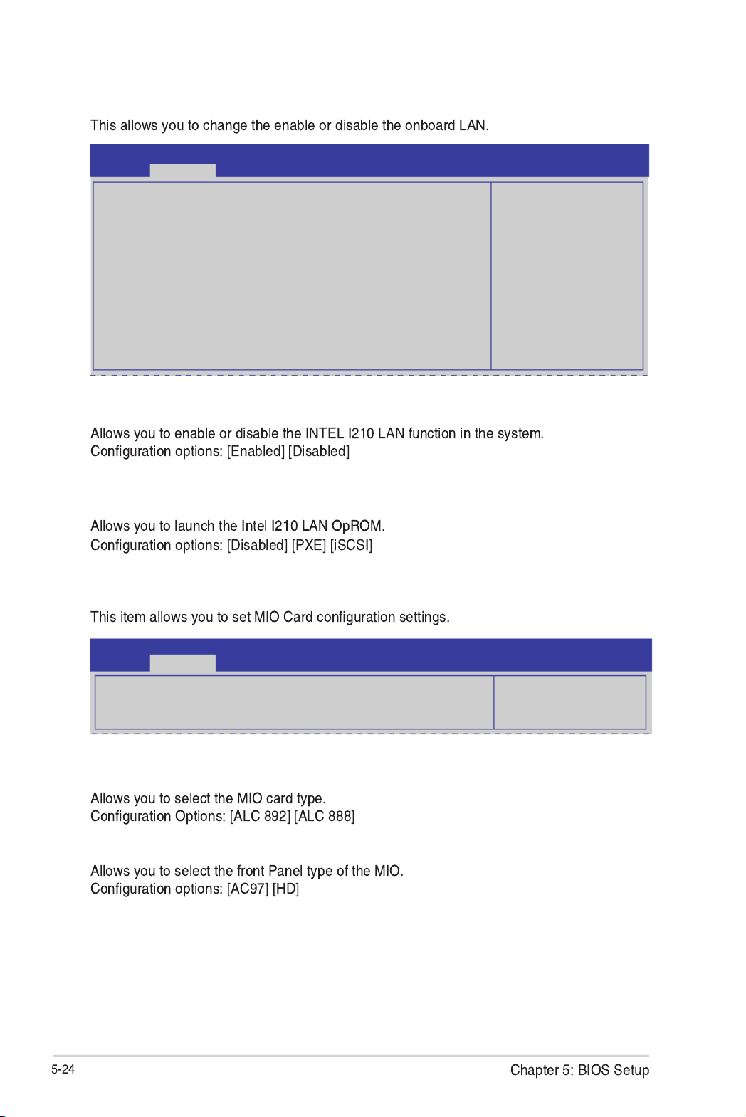
5.4.12 Onboard LAN Configuration
INTEL I210 LAN1 - LAN4 Enable [Enabled]
INTEL I210 LAN1/LAN2 OpROM [PXE], INTEL I210 LAN3/LAN4 OpROM
[Disabled]
Aptio Setup Utility - Copyright (C) 2013 American Megatrends, Inc.
Advanced
INTEL I210 LAN
Disable/Enable
Onboard LAN Conguration
INTEL I210 LAN1 MAC: 00:E0:18:10:18:E8
INTEL I210 LAN2 MAC: 00:E0:18:10:18:E9
INTEL I210 LAN3 MAC: 00:E0:18:10:18:EA
INTEL I210 LAN4 MAC: 00:E0:18:10:18:EB
INTEL I210 LAN1 Enable [Enabled]
INTEL I210 LAN1 OpROM [PXE]
INTEL I210 LAN2 Enable [Enabled]
INTEL I210 LAN2 OpROM [PXE]
INTEL I210 LAN3 Enable [Enabled]
INTEL I210 LAN3 OpROM [Disabled]
INTEL I210 LAN4 Enable [Enabled]
INTEL I210 LAN4 OpROM [Disabled]
5.4.13 MIO Card Configuration
MIO Card Type [ALC 892]
Front Panel Type [AC97]
Aptio Setup Utility - Copyright (C) 2013 American Megatrends, Inc.
Advanced
MIO Card Type
Set MIO Card
MIO Card Type [ALC 892]
Front Panel Type [AC97]
COM1/COM2 Console Redirection [Disabled/Enabled]
Console Redirection Settings Console Redirection
[Enabled]
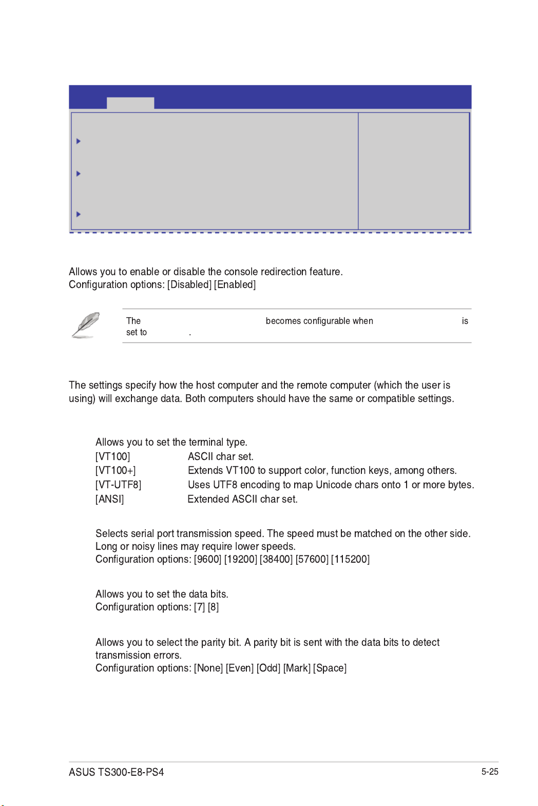
5.4.14 Serial Port Console Redirection
Aptio Setup Utility - Copyright (C) 2013 American Megatrends, Inc.
Advanced
Console Redirection
Enable or Disable.
COM1
Console Redirection [Disabled]
Console Redirection Settings
COM2
Console Redirection [Enabled]
Console Redirection Settings
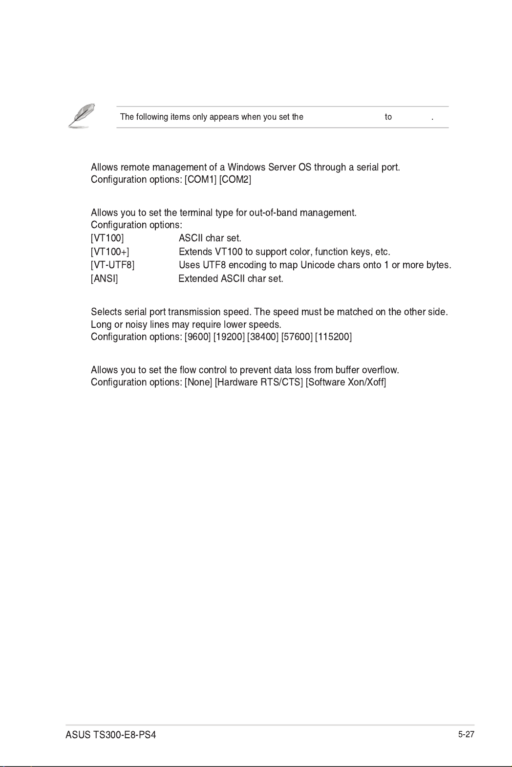
Serial Port for Out-of-Band Management/
Windows Emergency Management Services (EMS)
Console Redirection [Disabled]
Console Redirection Settings
COM1/COM2 Console Redirection Settings
Terminal Type [VT-UTF8]
Bits per second [57600]
Data Bits [8]
Parity [None]

Stop Bits [1]
Flow Control [Hardware RTS/CTS]
VT -UTF8 Combo Key Support [Enabled]
Recorder Mode [Disabled]
Resolution 100x31 [Enabled]
Legacy OS Redirection Resolution [80x24]
Putty Keypad [VT100]
Redirection After BIOS POST [Bootloader]
Console Redirection [Enabled]
Serial Port for Out-of-Band Management/Windows Emergency Management
Services (EMS) Settings
Out-of-Band Mgmt Port [COM1]
Terminal Type [VT-UTF8]
Bits per second [115200]
Flow Control [None]

5.4.16 APM
Restore AC Power Loss [Last State]
Power On By PCI [Disabled]
Power On By PCIE [Disabled]
Power On By RTC [Disabled]
RTC Alarm Date (Days) Hour/Minute/Second
EUP Ready [Disabled]
5.4.15 Runtime Error Logging Support
Aptio Setup Utility - Copyright (C) 2013 American Megatrends, Inc.
Advanced
Restore AC Power Loss [Last State]
Power On By PCI [Disabled]
Power On By PCIE [Disabled]
Power On By RTC [Disabled]
EuP Ready [Disabled]
Specify what state to
go to when power is re-
applied after a power
failure (G3 state).
Runtime Error Logging Support [Disabled]
Aptio Setup Utility - Copyright (C) 2013 American Megatrends, Inc.
Advanced
Runtime Error Logging Support [Disabled]

Network Stack [Disabled]
5.4.18 Intel RC Drivers Version Detail
5.4.17 Network Stack
Aptio Setup Utility - Copyright (C) 2013 American Megatrends, Inc.
Advanced
Network stack [Disable] Enable/Disable the
network stack (Pxe and
UEFI)
Aptio Setup Utility - Copyright (C) 2013 American Megatrends, Inc.
Advanced
Intel CPU RC Version 1.0.0.0
Memory RC Version 1.0.0.0
Intel SA RC Version 1.0.0.0
Intel PCH RC Version 1.0.0.0

5.5 Event Logs menu
Smbios Event Log [Enabled]
Erase Event Log [No]
When Log is Full [Do Nothing]
Change Smbios Event Log Settings
Change this to enable or disable
all features of Smbios Event
Logging during boot.
Enabling/Disabling Options
Smbios Event Log [Enabled]
Erasing Settings
Erase Event Log [No]
When Log is Full [Do Nothing]
NOTE: All values changed here do not take effect
until computer is restarted.
Aptio Setup Utility - Copyright (C) 2013 American Megatrends, Inc.
Main Advanced Event Logs Boot Monitor Security Tool Exit
Event Logs
Press <Enter> to change the
Smbios Event Log conguration.
Change Smbios Event Log Settings
View Smbios Event Log
View System Event Log
Aptio Setup Utility - Copyright (C) 2013 American Megatrends, Inc.
Main Advanced Event Logs Boot Monitor Security Tool Exit
Event Logs

5.6 Boot menu
Setup Prompt Timeout [xx]
Bootup NumLock State [On]
Full Screen Logo [Enabled]
Full Screen Logo [Enabled]
GateA20 Active [Upon Request]
Option ROM Messages [Force BIOS]
Number of seconds to wait
for setup activation key.
65535(0xFFFF) means
indenite waiting.
Boot Conguration
Setup Prompt Timeout 1
Bootup NumLock State [On]
Full Screen Logo [Enabled]
CSM16 Module Version 07.69
GateA20 Active [Upon Request]
Option ROM Messages [Force BIOS]
INT19 Trap Response [Immediate]
Boot Device Seeking [Endless PXE]
Boot Option Priorities
Boot Option #1 [P0: DVD ]
Boot Option #2 [P4: Harddisk 2.50G]
Boot Option #3 [Windows Boot Man..]
Network Device BBS Priorities
Hard Drive BBS Priorities
CSM parameters
Aptio Setup Utility - Copyright (C) 2013 American Megatrends, Inc.
Main Advanced Event Logs Boot Monitor Security Tool Exit
Boot

INT19 Trap Response [Immediate]
Boot Device Seeking [Endless PXE]
Boot Option Priorities
Network Device BBS Priorities / Hard Drive BBS Priorities
®

CSM Parameters
Launch CSM [Enabled]
Boot Option filter [Legacy only]
Launch PXE OpROM policy [Legacy only]
Launch Storage OpROM policy [Legacy only]
Launch Video OpROM policy [Legacy only]
Other PCI device ROM priority [Legacy OpROM]
This option controls if CSM
will be launched.
Launch CSM [Enabled]
Boot Option lter [Legacy only]
Launch PXE OpROM policy [Legacy only]
Launch Storage OpRom policy [Legacy only]
Launch Video OpRom policy [Legacy only]
Other PCI device ROM priority [Legacy OpROM]
Aptio Setup Utility - Copyright (C) 2013 American Megatrends, Inc.
Boot
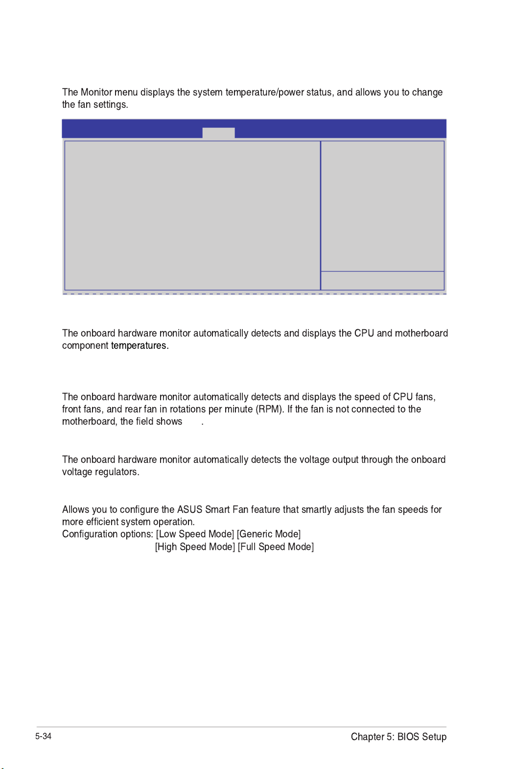
5.7 Monitor menu
CPU/MB/TR1 Temperature [xxx°C/xxx°F]
CPU_FAN1 Speed; FRNT_FAN1–3 Speed; REAR_FAN1 Speed [xxxx RPM] or
[Ignore] / [N/A]
N/A
VCORE1 Voltage: +12V, +5V, +1.5V, +3VSB, +3.3V, and VBAT
Fan Speed Control [Generic Mode]
Whisper/Generic/High/Speed/
Full Speed
Aptio Setup Utility - Copyright (C) 2013 American Megatrends, Inc.
Main Advanced Event Logs Boot Monitor Security Tool ExitMonitor
CPU Temperature : +58ºC/ +162ºF
MB Temperature : +52ºC/ +151ºF
TR1 Temperature : N/A
CPU_FAN1 Speed : 1054 RPM
REAR_FAN1 Speed : N/A
FRNT_FAN1 Speed : N/A
FRNT_FAN2 Speed : N/A
FRNT_FAN3 Speed : N/A
VCORE1 : +1.800 V
+12V : +12.288 V
+5V : +5.040 V
+1.5V : +1.504 V
+3VSB : +3.408 V
+3.3V : +1.296 V
VBAT : +3.344 V
FAN Speed Control [Generic Mode]

5.8 Security
Administrator Password
Set Setup Administrator
Password
Aptio Setup Utility - Copyright (C) 2013 American Megatrends, Inc.
Main Advanced Event Logs Boot Monitor Security Tool Exit
Security
Administrator Password
User Password
Clear Password
System Boot Menu
HDD Security Conguration:
P1: HardDisk
P2: HardDisk
Password Description
If ONLY the Administrator’s password is set, then
this only limits access to Setup and is only asked
for when entering Setup.
If ONLY the User’s password is set, then this
is a power on password and must be entered to
boot or enter Setup. In Setup the User will have
Administrator rights.
The password length must be
in the following range:
Minimum length 3
Maximum length 20
User Password
Yes
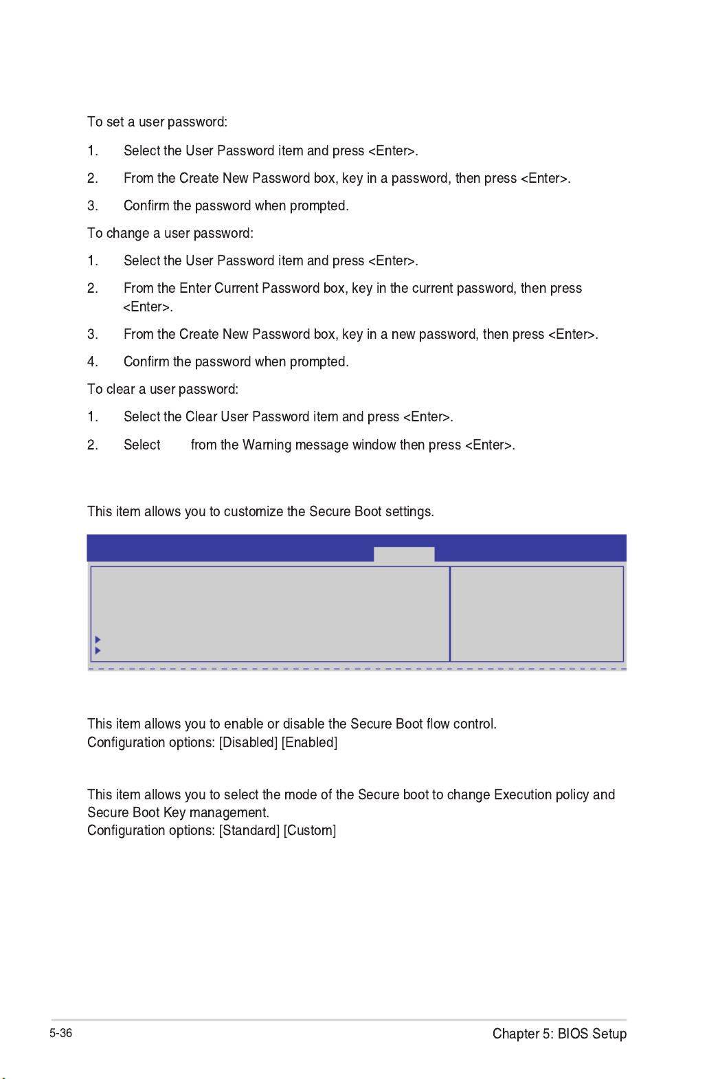
Secure Boot Menu
Secure Boot Control [Enabled]
Secure Boot Mode [Standard]
Secure Boot ow control.
Secure Boot can be enabled
only when Platform Key (PK)
is enrolled and Platform is
operating in User mode.
Aptio Setup Utility - Copyright (C) 2013 American Megatrends, Inc.
Security
Platform Mode Setup
Secure Boot Disabled
Secure Boot Control [Enabled]
Secure Boot Mode [Standard]
Image Execution Policy
Key Management

Internal FV [Always Execute]
Option ROM/Removable Media/Fixed Media [Deny Execute]
Key Management
Aptio Setup Utility - Copyright (C) 2013 American Megatrends, Inc.
Security
Image Execution Policy per
device path on Security
Violation.
Interval FV [Always Execute]
Option ROM [Deny Execute]
Removable Media [Deny Execute]
Fixed Media [Deny Execute]
Image Execution Policy
Install Factory default Secure
Boot Keys when System is in
Setup Mode
Aptio Setup Utility - Copyright (C) 2013 American Megatrends, Inc.
Security
Factory Default Key Provisioning [Disabled]
Install All Factory Default Keys
Platform Key (PK) NOT INSTALLED
Set new PK
Delete PK
Key Exchange Key Database (KEK) NOT INSTALLED
Set new KEK
Delete KEK
Append Var to KEK
Authorized Signature Database (DB) NOT INSTALLED
Set new DB
Delete DB
Append Var to DB
Forbidden Signature Database (DBX) NOT INSTALLED
Set new DBX
Delete DBX
Append Var to DBX
Factory Default Key Provisioning [Disabled]
Install All Factory Default Keys
Platform Key (PK)/Key Exchange Key Database (KEK)/Authorized Signature
Database (DB)/ Forbidden Signature Database (DBX)

5.10 Exit menu
Discard Changes & Exit
Yes
Save Changes & Reset
Start EzFlash utility
5.1.2 ASUS
EzFlash Utility
5.9 Tool menu
Press ENTER to run the utility
to select and update BIOS.
Start EzFlash
Aptio Setup Utility - Copyright (C) 2013 American Megatrends, Inc.
Main Advanced Event Logs Boot Monitor Security Tool Exit
Tool
Exit system setup without
saving any changes.
Discard Changes & Exit
Save Changes & Reset
Discard Changes & Reset
Restore Defaults
Boot Override
IBA GE Slot 0B00 v1404
IBA GE Slot 0B00 v1404
Windows Boot Manager
Launch EFI Shell from lesystem device
Aptio Setup Utility - Copyright (C) 2013 American Megatrends, Inc.
Main Advanced Event Logs Boot Monitor Security Tool Exit
Exit

Discard Changes & Reset
Restore Defaults
Yes
Launch EFI Shell from filesystem device
Produkt Specifikationer
| Mærke: | Asus |
| Kategori: | Server |
| Model: | TS300-E8-PS4 |
Har du brug for hjælp?
Hvis du har brug for hjælp til Asus TS300-E8-PS4 stil et spørgsmål nedenfor, og andre brugere vil svare dig
Server Asus Manualer

9 December 2024
6 Oktober 2024
21 September 2024
1 September 2024
30 August 2024
27 August 2024
27 August 2024
20 August 2024
19 August 2024
8 August 2024
Server Manualer
- Server QNAP
- Server Bosch
- Server Acer
- Server Sony
- Server HP
- Server D-Link
- Server Gigabyte
- Server Toshiba
- Server Lenovo
- Server Abus
- Server Planet
- Server Black Box
- Server TRENDnet
- Server Buffalo
- Server Medion
- Server Linksys
- Server Megasat
- Server Cisco
- Server Seagate
- Server Netgear
- Server Tripp Lite
- Server Western Digital
- Server Technics
- Server Digitus
- Server Dell
- Server Fujitsu
- Server MSI
- Server NEC
- Server APC
- Server LevelOne
- Server FLIR
- Server ZyXEL
- Server Eaton
- Server ELAC
- Server Synology
- Server Hikvision
- Server Monacor
- Server AVerMedia
- Server Asustor
- Server Kramer
- Server Hanwha
- Server LaCie
- Server Naim
- Server Fantec
- Server Provision-ISR
- Server Quantum
- Server Axis
- Server ACTi
- Server Digi
- Server ATen
- Server Teo
- Server Vimar
- Server Smart-AVI
- Server Intel
- Server Supermicro
- Server StarTech.com
- Server Conceptronic
- Server Rocstor
- Server IStarUSA
- Server Blackmagic Design
- Server Lindy
- Server Veritas
- Server Promise Technology
- Server Sitecom
- Server HGST
- Server AMX
- Server Intellinet
- Server Iomega
- Server Silverstone
- Server Geovision
- Server Ernitec
- Server KanexPro
- Server Gefen
- Server Moxa
- Server C2G
- Server Allnet
- Server Maxdata
- Server Matrox
- Server Valcom
- Server Freecom
- Server IoSafe
- Server Revox
- Server Luxman
- Server G-Technology
- Server Areca
- Server SEH
- Server Ibm
- Server Sonnet
- Server TAIDEN
- Server SIIG
- Server Advantech
- Server Mobotix
- Server Extron
- Server Avocent
- Server Silex
- Server Middle Atlantic
- Server In Win
- Server Sun
- Server Atlona
- Server MvixUSA
- Server Dual Bay
- Server Raidsonic
- Server EMC
- Server Infortrend
- Server Opengear
- Server EXSYS
- Server Raritan
- Server Chenbro Micom
- Server Mr. Signal
- Server Atlantis Land
- Server Lantronix
- Server NETSCOUT
- Server Origin Storage
- Server IMC Networks
Nyeste Server Manualer

9 Marts 2025
9 Marts 2025
9 Marts 2025

30 Januar 2025
30 Januar 2025
23 Januar 2025
23 Januar 2025
23 Januar 2025
23 Januar 2025
23 Januar 2025