Asus Z10PE-D8 WS Manual
Læs nedenfor 📖 manual på dansk for Asus Z10PE-D8 WS (202 sider) i kategorien Bundkort. Denne guide var nyttig for 11 personer og blev bedømt med 4.5 stjerner i gennemsnit af 2 brugere
Side 1/202

Z10PE-D8 WS

Copyright © 2019 ASUSTeK COMPUTER INC. All Rights Reserved.
Contents
Notices viii .....................................................................................................................
Safety information x .......................................................................................................
About this guide xi .........................................................................................................
Z10PE-D8 WS specifications summary xiii ..................................................................
Chapter 1: Product Introduction
1.1 Welcome! .................................................................................................... 1-2
1.2 Package contents 1-2 ......................................................................................
1.3 Serial number label 1-3 ....................................................................................
1.4 Special features.......................................................................................... 1-3
Chapter 2: Hardware Information
2.1 Before you proceed 2-2 ...................................................................................
2.2 Motherboard overview 2-3 ...............................................................................
2.3 Central Processing Unit (CPU) 2-7 .................................................................
2.4 System memory 2-12 .......................................................................................
2.5 Expansion slots 2-15 ........................................................................................
Contents
2.6 Onboard buttons and switches 2-18 ..............................................................
2.7 Onboard LEDs 2-20 ..........................................................................................
2.8 Jumpers .................................................................................................... 2-28
2.9 Connectors ............................................................................................... 2-33
Chapter 3: Powering Up
3.1 Starting up for the first time 3-2 ......................................................................
3.2 Powering off the computer 3-3 ........................................................................
Chapter 4: BIOS Setup
4.1 Managing and updating your BIOS 4-2 ..........................................................
4.2 BIOS setup program 4-6 ..................................................................................
4.3 Main menu 4-9 ..................................................................................................
4.4 AiTweaker menu 4-10 .......................................................................................

Contents
4.5 Advanced menu 4-13 .......................................................................................
4.6 IntelRCSetup menu 4-29 ..................................................................................
4.7 Server Mgmt menu 4-45 ...................................................................................
4.8 Event Logs menu 4-49 .....................................................................................
4.9 Monitor menu 4-51 ...........................................................................................
4.10 Security menu 4-52 ..........................................................................................
4.11 Boot menu 4-55 ................................................................................................
4.12 Tool menu 4-56 .................................................................................................
4.13 Exit menu 4-57 ..................................................................................................

Chapter 5: RAID Configuration
5.1 Setting up RAID 5-2 ..........................................................................................
5.2 LSI Software RAID Configuration Utility 5-4 .................................................
5.3 Intel® Rapid Storage Technology enterprise
SATA/SSATA Option ROM Utility 5-24 ...........................................................
5.4 Intel® Rapid Storage Technology enterprise (Windows) 5-32 ......................
Contents

Contents
Chapter 6: Driver Installation
6.1 RAID driver installation 6-2 .............................................................................
6.2 Software drivers and utilities installation 6-13 ..............................................
6.3 Running the Support DVD 6-13 .......................................................................
6.4 Installing the drivers and utilities 6-16 ..........................................................
6.5 Running the utilities 6-20 .................................................................................
Appendix A: Reference Information
A.1 Z10PE-D8 WS block diagram A-2 ...................................................................
A.2 Audio I/O connections A-3 ..............................................................................
ASUS contact information 1 ..........................................................................................

Notices
Federal Communications Commission Statement

REACH
Compliance Statement of Innovation, Science and Economic
Development Canada (ISED)
Déclaration de conformité de Innovation, Sciences et
Développement économique Canada (ISED)

Safety information
Electrical safety
Operation safety
DO NOT
DO NOT

About this guide
How this guide is organized
• Chapter1:ProductIntroduction
• Chapter2:HardwareInformation
• Chapter3:PoweringUp
• Chapter4:BIOSSetup
• Chapter5:RAIDConfiguration
• Chapter6:DriverInstallation
• Appendix:ReferenceInformation
Where to find more information
1. ASUS websites
2. Optional documentation

Conventions used in this guide
Typography
Bold text
Italics
Command
format A:/S
DANGER/WARNING:
CAUTION:
IMPORTANT:
NOTE:

Z10PE-D8 WS specifications summary
CPU
* Refer to www.asus.com for CPU support list
Chipset
Memory
* Actual memory frequency differs from Intel CPU types and memory
modules. 2400MT/s is supported only with E5-2600 v4 CPUs.
** Refer to www.asus.com for the memory QVL (Qualified Vendors Lists).
Expansion slots
* This motherboard is ready to support PCIe 3.0 specification. Functions will
be available when using PCIe 3.0-compliant devices. Refer to
www.asus.com for the latest updates and information.
VGA Output
Multi-GPU support
Storage
Intel® C612 with Intel RSTe:
ASMedia®
SATA Express controller***:
* M.2 Socket 3 supports M Key and type 2260/2280/22110 storage devices.
** LSI MegaRAID only support SATA Controller
*** These functions will work depending on the CPU installed.

Z10PE-D8 WS specifications summary
LAN
Audio
USB
ASMedia USB 3.0 controllers
Intel®C612 Chipset
Key Selling Points
Workstation Unique
Features

Z10PE-D8 WS specifications summary
* Refer to ASUS Server AVL for latest update.
Back Panel I/O Ports
Internal I/O Connectors
BIOS Features
Manageability
Support DVD
Form Factors


Product Introduction
Chapter 1: Product Introduction

1.1 Welcome!
1.2 Package contents
Standard Gift Box
Pack Standard Bulk Pack
Cables
VGA cable with bracket
SATA 6G cable
COM port cable
I/O Modules 2-port USB 2.0
Accessories
IO shield
2-Way SLI Bridge
connector
3-Way SLI Bridge
connector
4-Wat SLI Bridge
connector
ASWM Enterprise SDVD
Application CD Support CD
Packing Qty.
Optional items Description

1.4 Special features
1.4.1 Product highlights
Latest Processor Technology
Intel AVX 2.0
Next Generation of processor power management
DDR4 memory support
1.3 Serial number label
xxS1xxxxxxxx
xxS1xxxxxxxx
Z10PE-D8 WS Made
in
Taiwan
合格
PCI Express 3.0
M.2 Support
Intel® C612 Series Chipset
Intel® I210AT LAN Solution
Serial ATA III technology
Temperature, fan, and voltage monitoring
SATA Express support

1.4.2 Innovative ASUS features
ASUS Fan Speed control technology
Best graphics performance for 4-way NVIDIA® GeForce® SLI™
Q-Code Logger
ProCool Connector
ASUS Dr. Power
Ai Charger+
USB Charger+


2.1 Before you proceed

2.2.4 Layout contents
Jumpers Page
Slots/Socket Page
Onboard buttons and switches Page
Onboard LEDs Page

Rear panel connectors Page
Internal connectors Page

2.3.1 Installing the CPU
2.3 Central Processing Unit (CPU)
Triangle mark

Load lever
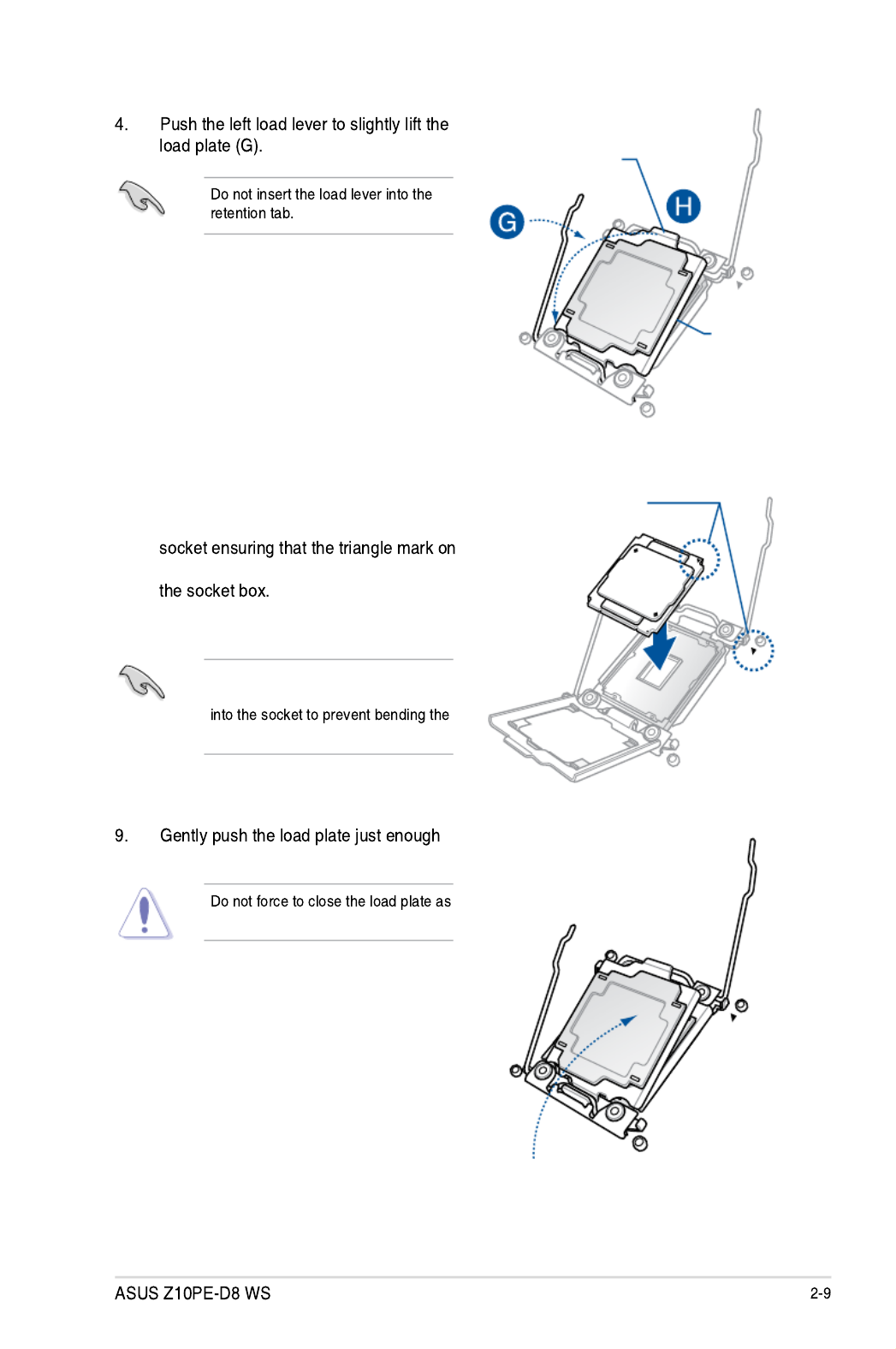
toletitsitontopoftheCPU.
itmaydamagetheCPU.
TheCPUtsinonlyonecorrect
orientation.DONOTforcetheCPU
CPUpinsonthesocket.
6. GettheCPU.
7. AlignandpositiontheCPUoverthe
theCPUmatchesthetrianglemarkon
8. InstalltheCPUintotheslot.
Triangle mark
Load plate
edge of the Load plate
5. Holdtheedgethengentlylifttheload
plate(H).

2-10 Chapter 2: Hardware Information
10. Pushdowntherightloadlever(I)ensuringthattheedgeoftheloadplateisxedand
tuckedsecurelyunderthelever(J)theninsert the right load lever under the retention
tab(K).
The PnP cap pops out of the load plate when the right load lever is inserted into the
retention tab.
KeepthePnPcap.ASUSwillprocessReturnMerchandiseAuthorization(RMA)requests
onlyifthemotherboardcomeswiththePnPcapontheLGA2011socket.
11. Pushdowntheleftloadlever(L)then
insertitundertheretentiontab(M). Retention tab
PnP cap
ASUS Z10PE-D8 WS 2-11
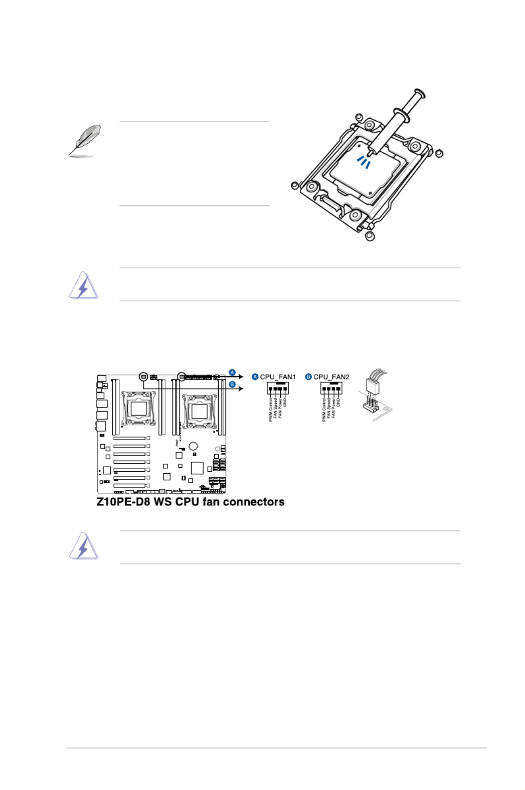
13. ConnecttheCPUfancabletotheconnectoronthemotherboardlabeledCPU_FAN1/
CPU_FAN2.
DONOTforgettoconnecttheCPUfanconnector!Hardwaremonitoringerrorscanoccurif
you fail to plug this connector.
TheThermalInterfaceMaterialistoxicandinedible.DONOTeatit.Ifitgetsintoyoureyes
ortouchesyourskin,washitoffimmediately,andseekprofessionalmedicalhelp.
• EnsurethattheThermalInterface
Materialisspreadinaneventhin
layer.
• Someheatsinkscomewithpre-
appliedThermalInterfaceMaterial.
Ifso,skipthisstep.
12. ApplysomeThermalInterfaceMaterial
totheexposedareaoftheCPUthatthe
heatsink will be in contact with.
2-12 Chapter 2: Hardware Information
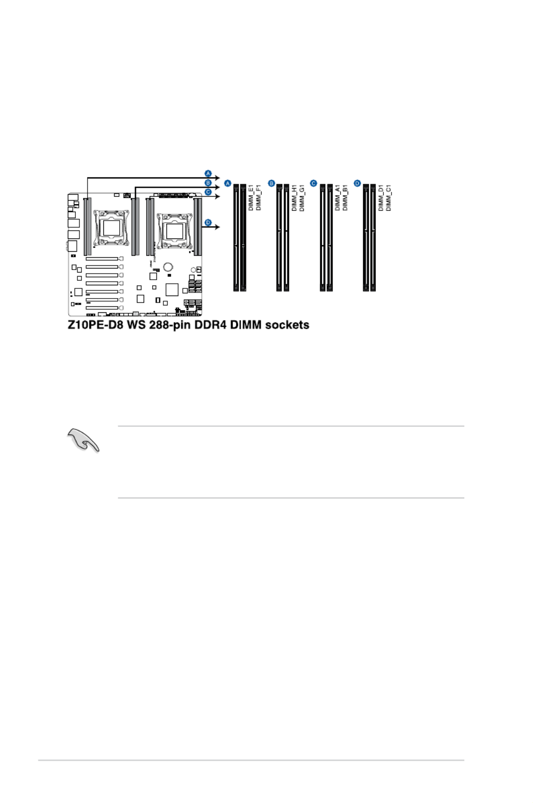
2.4 System memory
2.4.1 Overview
Themotherboardcomeswitheight(8)DoubleDataRate4(DDR4)DualInlineMemory
Modules(DIMM)sockets.
ThegureillustratesthelocationoftheDDR4DIMMsockets:
2.4.2 Memory Configurations
Youmayinstall4GB,8GB,16GB,and32GBRDIMMsor32GBand64GBLR-DIMMsinto
theDIMMsocketsusingthememorycongurationsinthissection.
• RefertoASUSServerAVLfortheupdatedlistofcompatibleDIMMs.
• WheninstallingDIMMs,alwaysstartfromslotA1(CPU1)andE1(CPU2).
• AlwaysinstallDIMMswiththesameCASlatency.Foroptimumcompatibility,itis
recommended that you obtain memory modules from the same vendor.
ASUS Z10PE-D8 WS 2-13
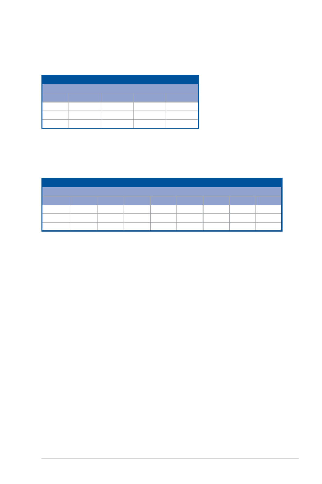
Single CPU configuration (must be installed on CPU1)
DIMM
A1 B1 C1 D1
1 DIMM P
2 DIMMs P P
4 DIMMs P P P P
Dual CPU configuration
YoucanrefertothefollowingrecommendedmemorypopulationforadualCPUconguration.
Single CPU configuration
YoucanrefertothefollowingrecommendedmemorypopulationforasingleCPU
conguration.
Dual CPU configuration
DIMM
A1 B1 C1 D1 E1 F1 G1 H1
2 DIMMs P P
4 DIMMs P P P P
8 DIMMs PPPPPPPP
2-14 Chapter 2: Hardware Information
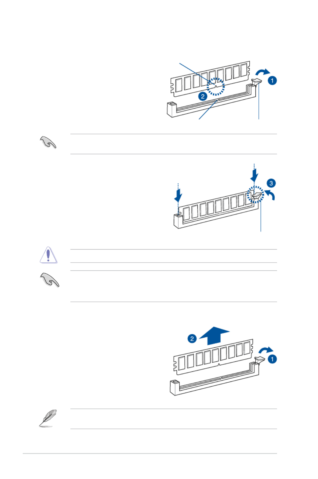
2.4.3 Installing a DIMM on a single clip DIMM socket
3. HoldtheDIMMatbothendstheninsert
theDIMMintothesocket.Applyforceto
bothendsoftheDIMMsimultaneously
until the retaining clip clicks into place
andtheDIMMisseatedsecurelyin
place.
1. Press the retaining clip outward to
unlocktheDIMMsocket.
2. AlignaDIMMonthesocketsuchthat
thenotchontheDIMMmatchesthe
DIMMslotkeyonthesocket.
1. Press the retaining clip outward to
unlocktheDIMM.
2. RemovetheDIMMfromthesocket.
Removing a DIMM from a single clip DIMM socket
• ToinstalltwoormoreDIMMs,refertotheuserguidebundledwiththemotherboard
package.
• Refertotheuserguideforqualiedvendorlistsofthememorymodules.
SupporttheDIMMlightlywithyourngerswhenpressingtheretainingclips.TheDIMM
mightgetdamagedwhenitipsoutwithextraforce.
AlwaysinserttheDIMMintothesocketVERTICALLYtopreventDIMMnotchdamage.
ADIMMiskeyedwithanotchsothatittsinonlyonedirection.DONOTforceaDIMMinto
asocketinthewrongdirectiontoavoiddamagingtheDIMM.
Unlocked retaining clip
DIMM notch
DIMM slot key
Locked Retaining Clip

2-16 Chapter 2: Hardware Information
* These IRQs are usually available for ISA or PCI devices.
IRQ Priority Standard function
0 1 SystemTimer
1 2 KeyboardController
2 - Programmable Interrupt
3* 11 CommunicationsPort(COM2)
4* 12 CommunicationsPort(COM1)
5* 13 --
6 14 FloppyDiskController
7* 15 --
8 3 SystemCMOS/RealTimeClock
9* 4 ACPIModewhenused
10* 5 IRQHolderforPCISteering
11* 6 IRQHolderforPCISteering
12* 7 PS/2CompatibleMousePort
13 8 Numeric Data Processor
14* 9 PrimaryIDEChannel
15* 10 SecondaryIDEChannel
2.5.3 Interrupt assignments
Standard Interrupt assignments
2.5.4 PCI Express x16 slot (x16 link)
TheonboardPCIE1and3provideonex16Gen3linktoCPU1(Autoswitchtox8linkifPCIE
2 and 4 are occupied);TheonboardPCIE5and7provideonex16Gen3linktoCPU2.These
slotssupportVGAcardsandvariousserverclasshighperformanceadd-oncards.
2.5.5 PCI Express x16 slot (x8 link)
TheonboardPCIE6providesonex8Gen3linktoCPU2;TheonboardPCIE2and4provide
onex8Gen3linktoCPU1.TheseslotsupportVGACardsandvariousserverclasshigh
performance add-on cards.
ASUS Z10PE-D8 WS 2-17
PCIE1 1xPCIEx16(x16Gen3Link)
(NearCPUsocket.Autoswitchtox8Linkifslot2isoccupied)
PCIE2 1xPCIEX16(x8Gen3Link)
PCIE3 1xPCIEx16(x16Gen3Link)
(Autoswitchtox8Linkifslot4isoccupied)
PCIE4 1xPCIEX16(x8Gen3Link)
PCIE5 1xPCIEx16(x16Gen3Link)
PCIE6 1xPCIEx16(x8Gen3Link)
PCIE7 1xPCIEx16(x16Gen3Link)
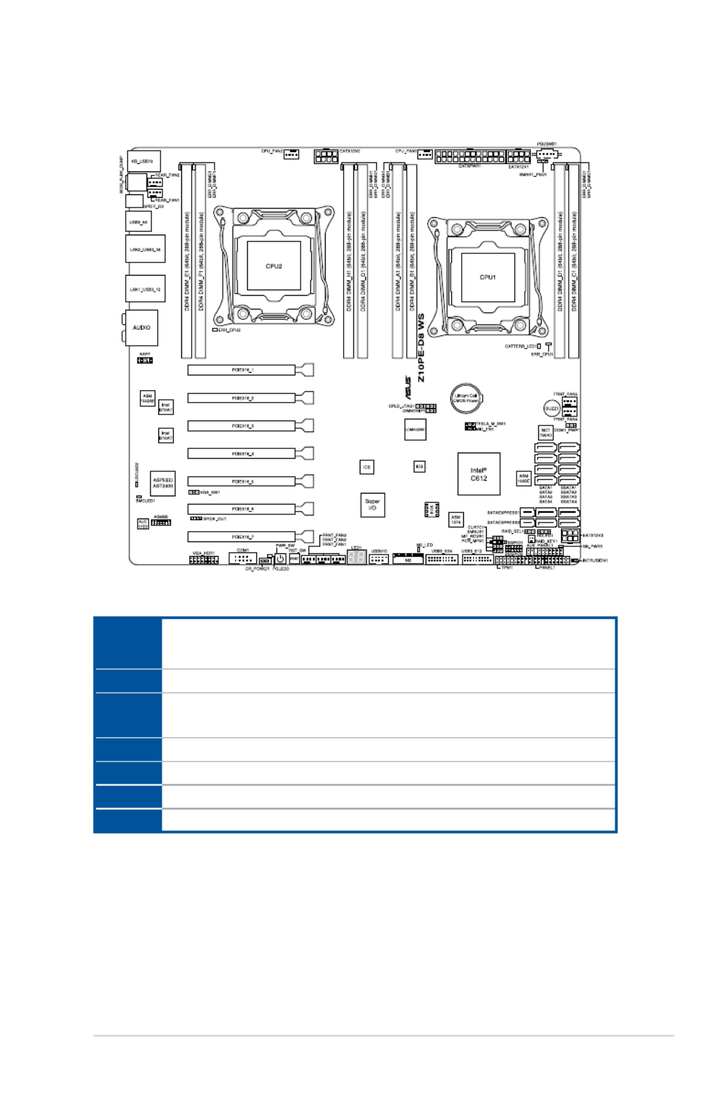
Motherboard Layout

2-18 Chapter 2: Hardware Information
1. Power-on
The motherboard comes with a power-on switch that allows you to power up or wake
up the system. The switch also lights up when the system is plugged to a power source
indicating that you should shut down the system and unplug the power cable before
removing or plugging in any motherboard component. The illustration below shows the
location of the onboard power-on switch.
2.6 Onboard buttons and switches
Onboardswitchesallowyoutone-tuneperformancewhenworkingonabareoropen-
case system. This is ideal for overclockers and gamers who continually change settings to
enhance system performance.
2. Reset button (RESET)
Press the reset switch to reboot the system.

ASUS Z10PE-D8 WS 2-19
3. Dr. Power switch (DR_POWER)
Toggle this switch to enable or disable the Dr. Power feature of the system.

2-20
1. Memory Error LED (ERR_DIMMA1, ERR_DIMMB1, ERR_DIMMC1, ERR_DIMMD1,
ERR_DIMME1, ERR_DIMMF1, ERR_DIMMG1, ERR_DIMMH1)
2.7 Onboard LEDs
2. Baseboard Management Controller LED (BMC_LED1)
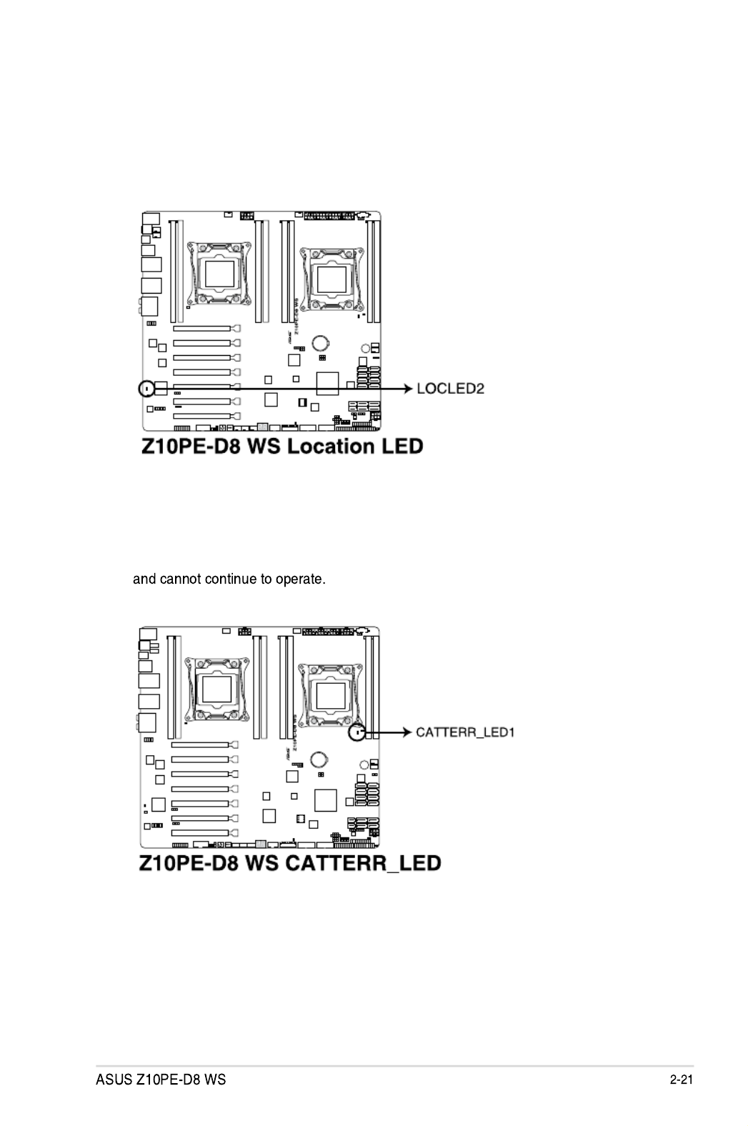
3. Location LED (LOCLED2)
ThisonboardLEDlightsupwhentheLocationbuttonontheserverispressedorwhen
triggeredbyasystemmanagementsoftware.TheLocationLEDhelpsvisuallylocate
andquicklyidentifytheserverinerroronaserverrack.
4. CATT LED (CATTERR_LED1)
TheCATTLEDindicatesthatthesystemhasexperiencedafatalorcatastrophicerror

2-22 Chapter 2: Hardware Information
5. CPU Warning LED (ERR_CPU1, ERR_CPU2)
6. M2 LED (M2_LED)
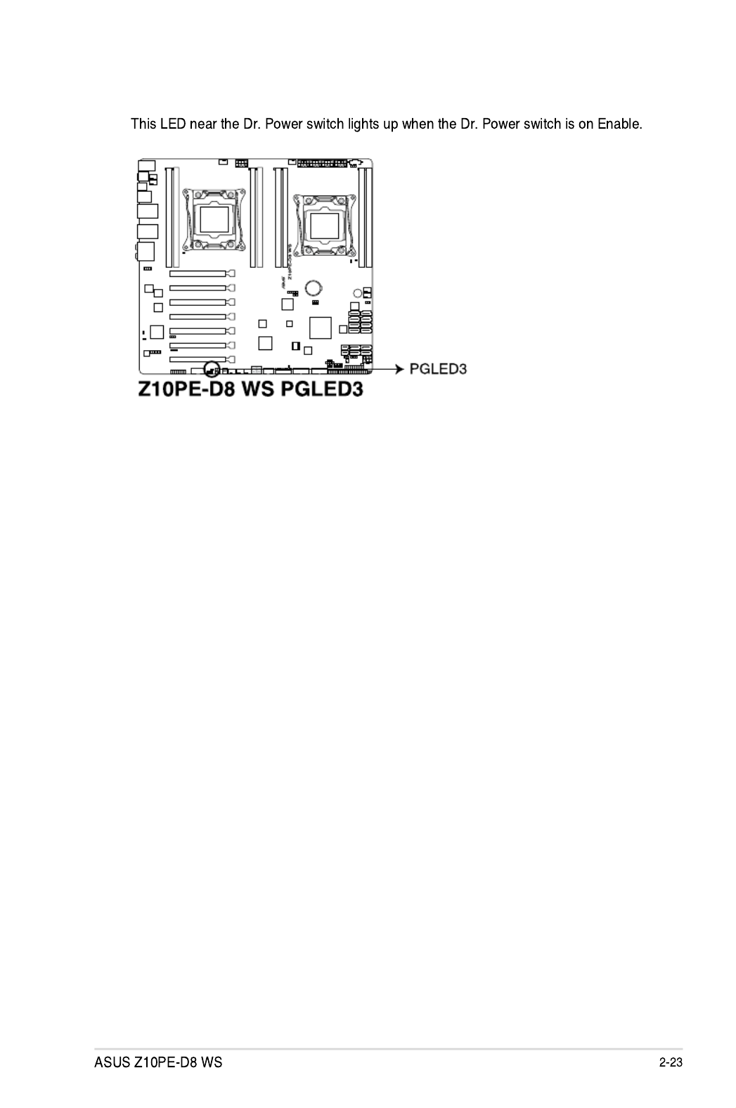
7. ASUS Dr. Power LED (PGLED3)

2-24 Chapter 2: Hardware Information
8. Q-Code LED (LED1)
TheQ-CodeLEDdesignprovidesyouthe2-digitdisplay,allowingyoutoknowthe
systemstatus.RefertotheQ-codetablebelowfordetails.
Code Description
00 Not used
01 Poweron.Resettypedetection(soft/hard).
02 APinitializationbeforemicrocodeloading
03 SystemAgentinitializationbeforemicrocodeloading
04 PCHinitializationbeforemicrocodeloading
06 Microcodeloading
07 APinitializationaftermicrocodeloading
08 SystemAgentinitializationaftermicrocodeloading
09 PCHinitializationaftermicrocodeloading
0A Initialization after microcode loading
0B Cacheinitialization
0C – 0D ReservedforfutureAMISECerrorcodes
0E Microcodenotfound
0F Microcodenotloaded
10 PEICoreisstarted
11 – 14 Pre-memoryCPUinitializationisstarted
15 – 18 Pre-memorySystemAgentinitializationisstarted
19 – 1C Pre-memoryPCHinitializationisstarted
2B – 2F Memoryinitialization
30 ReservedforASL(seeASLStatusCodessectionbelow)
Q-Code table

2-26 Chapter 2: Hardware Information
Code Description
63 – 67 CPUDXEinitializationisstarted
68 PCIhostbridgeinitialization
69 SystemAgentDXEinitializationisstarted
6A SystemAgentDXESMMinitializationisstarted
6B – 6F SystemAgentDXEinitialization(SystemAgentmodulespecic)
70 PCHDXEinitializationisstarted
71 PCHDXESMMinitializationisstarted
72 PCHdevicesinitialization
73 – 77 PCHDXEInitialization(PCHmodulespecic)
78 ACPImoduleinitialization
79 CSMinitialization
7A – 7F ReservedforfutureAMIDXEcodes
90 BootDeviceSelection(BDS)phaseisstarted
91 Driver connecting is started
92 PCIBusinitializationisstarted
93 PCIBusHotPlugControllerInitialization
94 PCIBusEnumeration
95 PCIBusRequestResources
96 PCIBusAssignResources
97 ConsoleOutputdevicesconnect
98 Consoleinputdevicesconnect
99 SuperIOInitialization
9A USBinitializationisstarted
9B USBReset
9C USBDetect
9D USBEnable
9E – 9F ReservedforfutureAMIcodes
A0 IDEinitializationisstarted
A1 IDEReset
A2 IDEDetect
A3 IDEEnable
A4 SCSIinitializationisstarted
A5 SCSIReset
A6 SCSIDetect
A7 SCSIEnable
A8 SetupVerifyingPassword
A9 StartofSetup
AA ReservedforASL(seeASLStatusCodessectionbelow)
AB SetupInputWait
Q-Code table (continued)

ASUS Z10PE-D8 WS 2-27
Code Description
AC ReservedforASL(seeASLStatusCodessectionbelow)
AD ReadyToBootevent
AE LegacyBootevent
AF ExitBootServicesevent
B0 RuntimeSetVirtualAddressMAPBegin
B1 RuntimeSetVirtualAddressMAPEnd
B2 LegacyOptionROMInitialization
B3 SystemReset
B4 USBhotplug
B5 PCIbushotplug
B6 Clean-upofNVRAM
B7 CongurationReset(resetofNVRAMsettings)
B8– BF ReservedforfutureAMIcodes
D0 CPUinitializationerror
D1 SystemAgentinitializationerror
D2 PCHinitializationerror
D3 SomeoftheArchitecturalProtocolsarenotavailable
D4 PCIresourceallocationerror.OutofResources
D5 NoSpaceforLegacyOptionROM
D6 NoConsoleOutputDevicesarefound
D7 NoConsoleInputDevicesarefound
D8 Invalid password
D9 ErrorloadingBootOption(LoadImagereturnederror)
DA BootOptionisfailed(StartImagereturnederror)
DB Flash update is failed
DC Resetprotocolisnotavailable
Q-Code table (continued)
Code Description
0x01 SystemisenteringS1sleepstate
0x02 SystemisenteringS2sleepstate
0x03 SystemisenteringS3sleepstate
0x04 SystemisenteringS4sleepstate
0x05 SystemisenteringS5sleepstate
0x10 SystemiswakingupfromtheS1sleepstate
0x20 SystemiswakingupfromtheS2sleepstate
0x30 SystemiswakingupfromtheS3sleepstate
0x40 SystemiswakingupfromtheS4sleepstate
0xAC SystemhastransitionedintoACPImode.InterruptcontrollerisinPICmode.
0xAA SystemhastransitionedintoACPImode.InterruptcontrollerisinAPICmode.
ACPI/ASL Checkpoints

2-28 Chapter 2: Hardware Information
2.8 Jumpers
1. Clear RTC RAM (CLRTC1)
ThisjumperallowsyoutocleartheRealTimeClock(RTC)RAMinCMOS.Youcan
cleartheCMOSmemoryofdate,time,andsystemsetupparametersbyerasingthe
CMOSRTCRAMdata.TheonboardbuttoncellbatterypowerstheRAMdatain
CMOS,whichincludesystemsetupinformationsuchassystempasswords.
ToerasetheRTCRAM:
1. Turn OFF the computer and unplug the power cord.
2. Movethejumpercapfrompins1–2(default)topins2–3.Keepthecaponpins2–3
forabout5–10seconds,thenmovethecapbacktopins1–2.
3. Plug the power cord and turn ON the computer.
4. Holddownthe<Del>keyduringthebootprocessandenterBIOSsetuptore-
enter data.
ExceptwhenclearingtheRTCRAM,neverremovethecaponCLRTCjumperdefault
position.Removingthecapwillcausesystembootfailure!
Ifthestepsabovedonothelp,removetheonboardbatteryandmovethejumperagainto
cleartheCMOSRTCRAMdata.AftertheCMOSclearance,reinstallthebattery.

ASUS Z10PE-D8 WS 2-29
2. VGA controller setting (VGA_SW1)
ThisjumperallowsyoutoenableordisabletheonboardVGAcontroller.Settopins1-2
toactivatetheVGAfeature.
3. SMBUS connection setting (TESLA_M_SW)
ThisjumperallowsyoutoselecttheconnectiontoBMCorPHCforPCIE1/3/5/7
SMBUS.

2-30 Chapter 2: Hardware Information
4. RAID selection jumper setting (3-pin RAID_SEL1)
ThisjumperallowsyoutoselectthePCHSATARAIDmodetouseLSIMegaRAID
software or Intel ®RapidStorageTechnologyenterprise3.0RAID.Placethejumper
capsoverpins1–2ifyouwanttousetheLSIMegaRAIDsoftwareRAIDUtility
(default);otherwise,placethejumpercapstopins2–3tousetheIntel ®RapidStorage
TechnologyEnterpriseOptionROMUtility.
5. ME firmware force recovery setting (3-pin ME_RCVR1)
ThisjumperallowsyoutoforceIntelManagementEngine(ME)bootfromrecovery
modewhenMEbecomecorrupted.

ASUS Z10PE-D8 WS 2-31
6. DDR4 thermal event setting (3-pin DIMMTRIP1)
ThisjumperallowsyoutoenableordisableDDR4DIMMthermalsensingeventpin.
7. PMBus 1.2 PSU select jumper (3-pin SMART_PSU1)
ThisjumperallowsyoutoselectPSUPMBusversion.Settopins1–2forPMBus,set
topins2–3forothers.

2-32 Chapter 2: Hardware Information
8. SATADOM Power jumper (3-pin DOM_PWR1)
Settopins2-3toenableSATA3porttosupportSATADOMdevices.

ASUS Z10PE-D8 WS 2-33
2.9 Connectors
2.9.1 Rear panel connectors
1. PS/2 mouse and keyboard port. ThisportisforaPS/2mouseorkeyboard.
2. Q-Code Logger button. ThisbuttonallowsyoutocheckQ-Codeeventlogs.Formore
information,refertothe Using the Q-Code logger section of this user guide.
3. Optical S/PDIF Out port. ThisportconnectstoSony/PhilipsDigitalInterconnect
Format(S/PDIF)compliantdevicesorampliedspeakers.
4. USB 3.0 ports 5 and 6. TheseUniversalSerialBus(USB)portsareavailablefor
connectingUSB3.0devices.
5. LAN 2 port (RJ-45). ThisportallowsGigabitconnectiontoaLocalAreaNetwork(LAN)
throughanetworkhub.RefertothetablebelowfortheLANportLEDindications.
6. LAN 1 port (RJ-45 port for LAN1 and BMC share). This port allows Gigabit connector
toaLocalAreaNetwork(LAN)throughanetworkhubforBMCmanagementfunction.
7. 8-channel Audio I/O. These audio ports connects to stereo audio sources or devices.
8. USB 2.0 ports 7 and 8. TheseUniversalSerialBus(USB)portsareavailablefor
connectingUSB2.0devices.
9. USB BIOS Flashback button. Press this button toeasilyupdatetheBIOSwithout
enteringtheexistingBIOSoroperatingsystem.Formoreinformation,refertothe
Using the USB BIOS Flashback section of this user guide.
10. USB 3.0 ports 3 and 4. TheseUniversalSerialBus(USB)portsareavailablefor
connectingUSB3.0devices.
11. USB 3.0 ports 1 and 2. TheseUniversalSerialBus(USB)portsareavailablefor
connectingUSB3.0devices.
• OnlyUSB2.0port7supportstheUSBCharger+function
• OnlyUSB3.0port5and6supportstheAICharger+function

2-34 Chapter 2: Hardware Information
LAN port LED indications
LAN port
LAN port
SPEED
LED
ACT/LINK
LED
Activity/Link LED Speed LED
Status Description Status Description
OFF No link OFF 10Mbpsconnection
Green OrangeLinked 100Mbpsconnection
Blinking Data activity Green 1 Gbps connection
Management LAN port
LAN port
SPEED
LED
ACT/LINK
LED
Activity/Link LED Speed LED
Status Description Status Description
OFF No link OFF 10Mbpsconnection
Orange OrangeLinked 100Mbpsconnection
Blinking Data activity Green 1 Gbps connection
Audio 2, 4, 6, or 8-channel configuration
Port Headset
2-channel
4-channel 6-channel 8-channel
LightBlue LineIn LineIn LineIn LineIn
Lime LineOut FrontSpeakerOut FrontSpeakerOut FrontSpeakerOut
Pink MicIn MicIn MicIn MicIn
Orange – – Center/Subwoofer Center/Subwoofer
Black – RearSpeakerOut RearSpeakerOut RearSpeakerOut
Gray – – SideSpeakerOut* SideSpeakerOut
* For Windows ® 8.1 only.
** For more information on the Audio I/o connections, see the Audio I/O connections section on the Appendix
chapter.

2-36 Chapter 2: Hardware Information
2.9.2 Internal connectors
1. Hard disk activity LED connector (4-pin HDLED1)
ThisLEDconnectorisforthestorageadd-oncardcableconnectedtotheSATAor
SASadd-oncard.ThereadorwriteactivitiesofanydeviceconnectedtotheSATAor
SASadd-oncardcausesthefrontpanelLEDtolightup.
2. USB 2.0 connectors (10-1 pin USB910)
TheseconnectorsareforUSB2.0ports.ConnecttheUSBmodulecablesto
connectorsUSB78andUSB910,theninstallthemodulestoaslotopeningattheback
ofthesystemchassis.TheseUSBconnectorscomplywithUSB2.0specicationthat
supportsupto480Mbpsconnectionspeed.

ASUS Z10PE-D8 WS 2-37
4. CPU, front and rear fan connectors (4-pin CPU_FAN1-2, FRNT_FAN1–5,
REAR_FAN1-2)
Thefanconnectorssupportcoolingfans.Connectthefancablestothefanconnectors
onthemotherboard,ensuringthattheblackwireofeachcablematchesthegroundpin
of the connector.
• DONOTforgettoconnectthefancablestothefanconnectors.Insufcientairow
inside the system may damage the motherboard components.
• Thesearenotjumpers!DONOTplacejumpercapsonthefanconnectors!
• AllfansfeaturetheASUSFanSpeedControltechnology.
3. USB 3.0 connector (20-1 pin USB3_34; USB3_E12)
ThisconnectorallowsyoutoconnectaUSB3.0moduleforadditionalUSB3.0front
orrearpanelports.WithaninstalledUSB3.0module,youcanenjoyallthebenetsof
USB3.0includingfasterdatatransferspeedsofupto5Gbps,fasterchargingtimefor
USB-chargeabledevices,optimizedpowerefciency,andbackwardcompatibilitywith
USB2.0.

2-38 Chapter 2: Hardware Information
5. Power supply SMBus connector (PSUSMB1)
This connector supplies power for low-speed system management communications.
6. Serial port connectors (10-1 pin COM1)
Theseconnectorsarefortheserial(COM)port.Connecttheserialportmodulecable
tooneoftheseconnectors,theninstallthemoduletoaslotopeningatthebackofthe
system chassis.

2-40 Chapter 2: Hardware Information
8. SATAEXPRESS connectors (7-pin SATAEXPRESS1 [upper port];
SATAEXPRESS2 [lower port])
TheseconnectorsconnecttoSerialATA6Gb/sharddiskdrivesviaSerialATA6Gb/s
signal cables.
• ASMediastoragecontrollercanonlysupportAHCImode.
• TheseSATAportsarefordatadrivesonly.
• TheSATAEXPRESS1-2connectorscansupportoneSATAExpressdeviceortwo
SATAdevices.
9. Serial General Purpose Input/Output connector (6-1 pin SGPIO1, SSGPIO1)
TheSGPIO1andSSGPIO1connectorsareusedfortheIntelRapidStorage
TechnologyEnterpriseSGPIOinterfacethatcontrolstheLEDpatterngeneration,
deviceinformation,andgeneralpurposedata.SGPIO1isthejumperforSATA1~4.
SSGPIO1isthejumperforSSATA1~4.
ASUS Z10PE-D8 WS 2-41
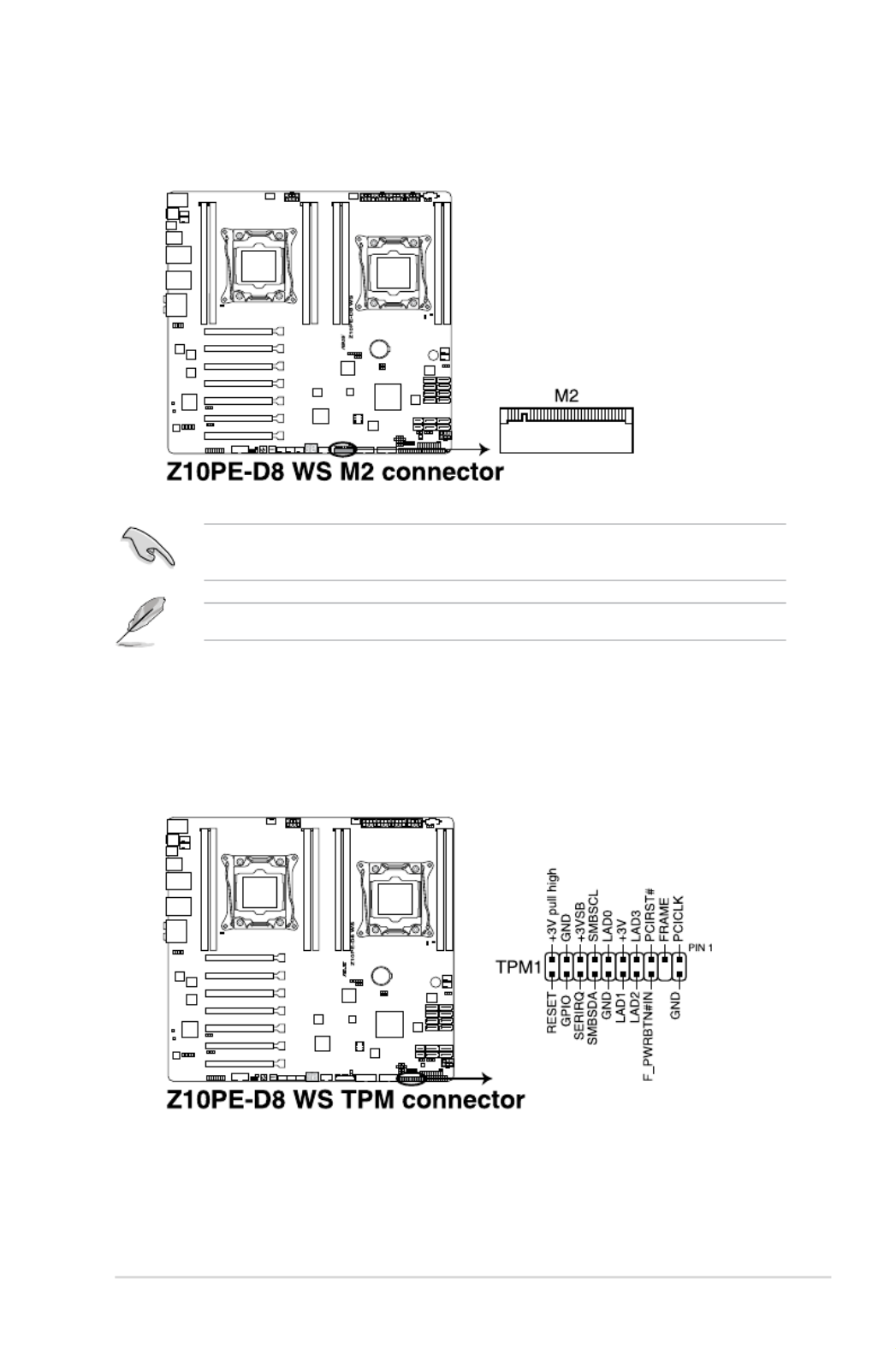
10. M.2 (NGFF) connector (NGFF1)
ThisconnectorallowsyoutoinstallanM.2device.
Thisconnectorsupportstype2260/2280/22110devicesonbothPCI-EandSATA
interface.
TheM.2(NGFF)deviceispurchasedseparately
11. Trusted Platform Module connector (20-1 pin TPM1)
ThisconnectorsupportsaTrustedPlatformModule(TPM)system,whichcansecurely
storekeys,digitalcerticates,passwords,anddata.ATPMsystemalsohelpsenhance
networksecurity,protectsdigitalidentities,andensuresplatformintegrity.
2-42 Chapter 2: Hardware Information
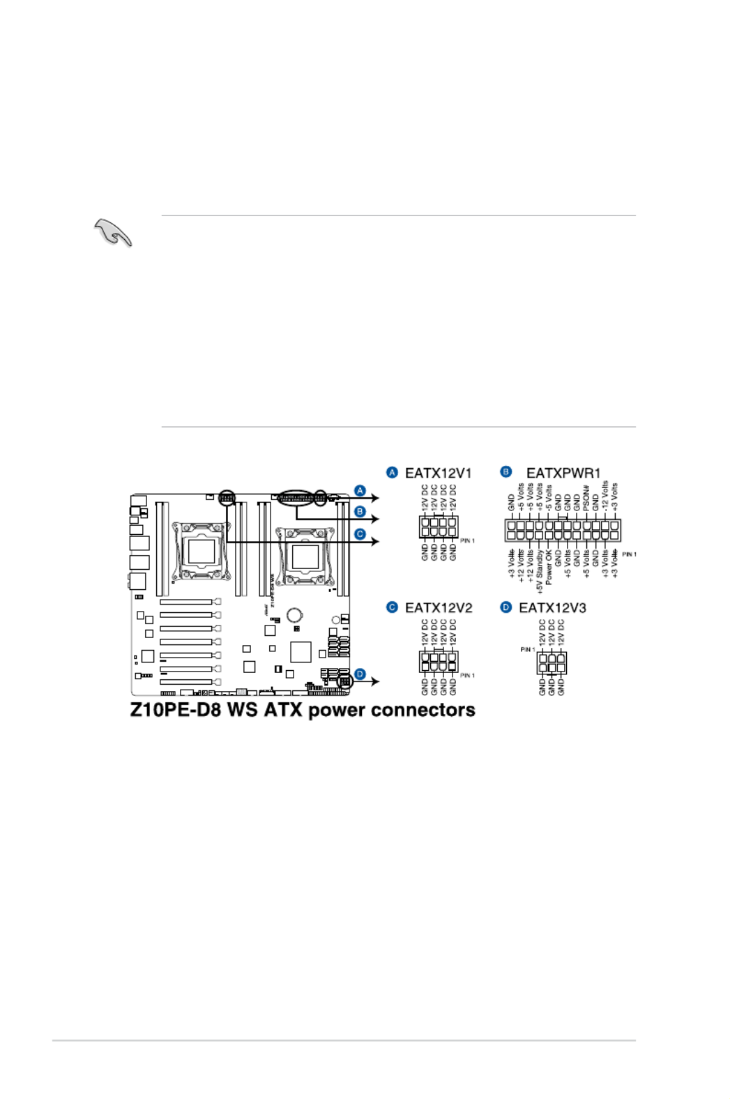
12. EATX power connectors (24-pin EATXPWR1; 8-pin EATX12V1/EATX12V2;
6-pin EATX12V3)
TheseconnectorsareforanEATXpowersupplyplugs.Thepowersupplyplugsare
designedtottheseconnectorsinonlyoneorientation.Findtheproperorientationand
pushdownrmlyuntiltheconnectorscompletelyt.
• DONOTforgettoconnectthe24+8+8-pinpowerplugs;otherwise,thesystemwillnot
boot up.
• Werecommendthatyouconnectthe6-pinEATX12V3powercablewheninstalling
morethantwoGPUorvideographicscard.
• UseofaPSUwithahigherpoweroutputisrecommendedwhenconguringasystem
with more power-consuming devices. The system may become unstable or may not
bootupifthepowerisinadequate.
• ThismotherboardsupportsEATX2.0PSUorlaterversion.
• Ensurethatyourpowersupplyunit(PSU)canprovideatleasttheminimumpower
requiredbyyoursystem.

2-44 Chapter 2: Hardware Information
14. System panel connector (20-1 pin PANEL1)
This connector supports several chassis-mounted functions.
(1) System power LED (3-pin PLED)
This3-pinconnectorisforthesystempowerLED.Connectthechassispower
LEDcabletothisconnector.ThesystempowerLEDlightsupwhenyouturnon
thesystempower,andblinkswhenthesystemisinsleepmode.
(2) Message LED (3-pin PLED)
This2-pinconnectorisforthemessageLEDcablethatconnectstothefront
messageLED.ThemessageLEDiscontrolledbyHardwaremonitortoindicate
an abnormal event occurrence.
(3) System warning speaker (4-pin SPEAKER)
This 4-pin connector is for the chassis-mounted system warning speaker. The
speaker allows you to hear system beeps and warnings.
(4) Hard disk drive activity LED (2-pin +HDLED)
This2-pinconnectorisfortheHDDActivityLED.ConnecttheHDDActivityLED
cabletothisconnector.TheHDDLEDlightsuporasheswhendataisreadfrom
orwrittentotheHDD.
(5) Power button/soft-off button (2-pin PWRSW)
This connector is for the system power button. Pressing the power button turns
thesystemonorputsthesysteminsleeporsoft-offmodedependingontheBIOS
settings. Pressing the power switch for more than four seconds while the system
is ON turns the system OFF.
(6) Reset button (2-pin RESET)
This 2-pin connector is for the chassis-mounted reset button for system reboot
without turning off the system power.
ASUS Z10PE-D8 WS 2-45
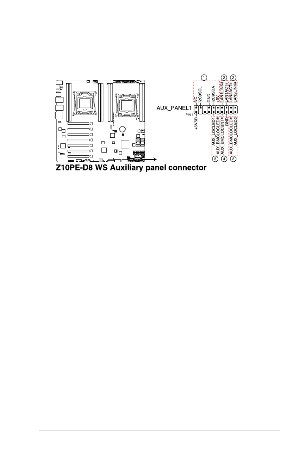
15. Auxiliary panel connector (20-2 pin AUX_PANEL1)
ThisconnectorisforadditionalfrontpanelfeaturesincludingfrontpanelSMB,locator
LEDandswitch,andLANLEDs.
(1) Front panel SMB (6-1 pin FPSMB)
TheseleadsconnectthefrontpanelSMBuscable.
(2) LAN activity LED (2-pin LAN12_LED)
TheseleadsareforGigabitLANactivityLEDsonthefrontpanel.
(3) Locator LED (2-pin LOCATORLED1 and 2-pin LOCATORLED2)
TheseleadsareforthelocatorLED1andLED2onthefrontpanel.Connectthe
LocatorLEDcablestothese2-pinconnector.TheLEDswilllightupwhenthe
Locatorbuttonispressed.
(4) Locator Button/Swich (2-pin LOCATORBTN)
Theseleadsareforthelocatorbuttononthefrontpanel.Thisbuttonqueriesthe
state of the system locator.
ASUS Z10PE-D8 WS 2-47
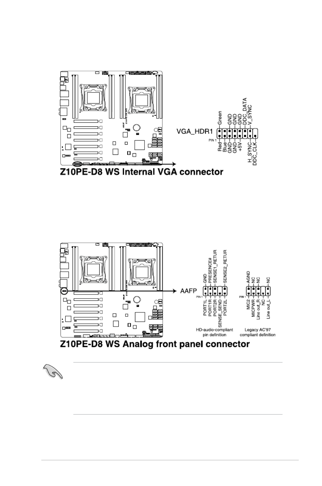
18. VGA connector (VGA_HDR1)
ThisconnectorsupportstheVGAHighDynamic-Rangeinterface.
19. Front panel audio connector (10-1 pin AAFP)
Thisconnectorisforachassis-mountedfrontpanelaudioI/Omodulethatsupports
eitherHDAudioorlegacyAC'97audiostandard.Connectoneendofthefrontpanel
audioI/Omodulecabletothisconnector.
• Werecommendthatyouconnectahigh-denitionfrontpanelaudiomoduletothis
connectortoavailofthemotherboard’shigh-denitionaudiocapability.
• Ifyouwanttoconnectahigh-denitionfrontpanelaudiomoduletothisconnector,set
the Front Panel Type itemintheBIOSsetupto [HD]; ifyouwanttoconnectanAC'97
frontpanelaudiomoduletothisconnector,settheitemto [AC97] .Bydefault,this
connector is set to [HD].

2-48 Chapter 2: Hardware Information

3
Powering Up
This chapter describes the power up sequence, and ways of
shutting down the system.
Chapter 3: Powering Up

3-2 Chapter 3: Powering Up
3.1 Starting up for the first time
1. After making all the connections, replace the system case cover.
2. Be sure that all switches are off.
3. Connect the power cord to the power connector at the back of the system chassis.
4. Connect the power cord to a power outlet that is equipped with a surge protector.
5. Turn on the devices in the following order:
a. Monitor
b. External storage devices (starting with the last device on the chain)
c. System power
6. After applying power, the system power LED on the system front panel case lights up.
For systems with ATX power supplies, the system LED lights up when you press the
ATX power button. If your monitor complies with “green” standards or if it has a “power
standby” feature, the monitor LED may light up or switch between orange and green
after the system LED turns on.
The system then runs the power-on self-test or POST. While the tests are running, the
BIOS beeps or additional messages appear on the screen. If you do not see anything
within 30 seconds from the time you turned on the power, the system may have failed
a power-on test. Check the jumper settings and connections or call your retailer for
assistance.
The following shows the possible beep codes and its corresponding error condition:
BIOS Beep codes
Beep Error condition
1 short Power supply surges detected during the previous power on.
1 short No Keyboard Detected.
1 short, 2 short No DIMM Detected.
1 short, 8 short No VGA Detected.
2 long Chassis Intrusion.
2 long BIOS-image Crash Detected.
7. At power on, hold down the <Del> key to enter the BIOS Setup. Follow the instructions
in Chapter 4.

3-4 Chapter 3: Powering Up

4
BIOS Setup
This chapter tells how to change the system settings through
the BIOS Setup menus. Detailed descriptions of the BIOS
parameters are also provided.
Chapter 4: BIOS Setup

4-2 Chapter 4: BIOS Setup
4.1 Managing and updating your BIOS
The following utilities allow you to manage and update the motherboard Basic Input/Output
System (BIOS) setup:
1. ASUS CrashFree BIOS 3
TorecovertheBIOSusingabootableUSBashdiskdrivewhentheBIOSlefailsor
gets corrupted.
2. ASUS EzFlash
UpdatestheBIOSusingaUSBashdisk.
3. BUPDATER
UpdatestheBIOSinDOSmodeusingabootableUSBashdiskdrive.
Refer to the corresponding sections for details on these utilities.
Recovering the BIOS from a USB flash drive
TorecovertheBIOSfromaUSBashdrive:
1. InserttheUSBashdrivewiththeoriginalorupdatedBIOSletooneUSBportonthe
system.
2. The utility will automatically recover the BIOS. It resets the system when the BIOS
recoverynished.
DO NOT shut down or reset the system while recovering the BIOS! Doing so would cause
system boot failure!
The recovered BIOS may not be the latest BIOS version for this motherboard. Visit the
ASUSwebsiteatwww.asus.comtodownloadthelatestBIOSle.
SaveacopyoftheoriginalmotherboardBIOSletoabootableUSBashdiskdrivein
case you need to restore the BIOS in the future. Copy the original motherboard BIOS using
the BUPDATER utility.
4.1.1 ASUS CrashFree BIOS 3 utility
TheASUSCrashFreeBIOS3isanautorecoverytoolthatallowsyoutorestoretheBIOSle
when it fails or gets corrupted during the updating process. You can update a corrupted BIOS
leusingaUSBashdrivethatcontainstheupdatedBIOSle.
PrepareaUSBashdrivecontainingtheupdatedmotherboardBIOSbeforeusingthis
utility.
4-3
ASUS Z10PE-D8 WS
6. PresstheUp/DownarrowkeystondtheBIOSle,andthenpress<Enter>toperform
the BIOS update process. Reboot the system when the update process is done.
• ThisfunctioncansupportdevicessuchasaUSBashdiskwithFAT32/16formatand
single partition only.
• DONOTshutdownorresetthesystemwhileupdatingtheBIOStopreventsystem
boot failure!
Ensure to load the BIOS default settings to ensure system compatibility and stability. Press
<F5>andselect Yes to load the BIOS default settings.
3. Press<Tab>toswitchtothe eld.Drive
4. PresstheUp/DownarrowkeystondtheUSBashdiskthatcontainsthelatestBIOS,
thenpress<Enter>.
5. Press<Tab>toswitchtothe eld.Folder Info
4.1.2 ASUS EZ Flash Utility
The ASUS EZ Flash Utility feature allows you to update the BIOS without having to use a
DOS-based utility.
Beforeyoustartusingthisutility,downloadthelatestBIOSfromtheASUSwebsiteat
www.asus.com.
To update the BIOS using EZ Flash Utility:
1. InserttheUSBashdiskthatcontainsthelatestBIOSleintotheUSBport.
2. Enter the BIOS setup program. Go to the menu then select Tool ASUS EZ Flash
Utility.Press<Enter>.
Current Platform
Platform : Z10PE-D8 WS
Version : 0215
Build date: 05/13/2014
New Platform
Platform : Z10PE-D8 WS
Version : 0217
Build date: 06/30/2014
ASUS Tek. EzFlash Utility
FS0
FS1
[Up/Down/Left/Right]:Switch [Enter]:Choose [q]:Exit

4-4 Chapter 4: BIOS Setup
4.1.3 BUPDATER utility
The succeeding BIOS screens are for reference only. The actual BIOS screen displays
may not be the same as shown.
TheBUPDATERutilityallowsyoutoupdatetheBIOSleintheDOSenvironmentusinga
bootableUSBashdiskdrivewiththeupdatedBIOSle.
Updating the BIOS file
ToupdatetheBIOSleusingtheBUPDATERutility:
1. VisittheASUSwebsiteatwww.asus.comanddownloadthelatestBIOSleforthe
motherboard.SavetheBIOSletoabootableUSBashdiskdrive.
2. Copy the BUPDATER utility (BUPDATER.exe) from the ASUS support website at
https://www.asus.com/support/tothebootableUSBashdiskdriveyoucreatedearlier.
3. BootthesysteminDOSmode,thenattheprompt,type:
BUPDATER /i[lename].CAP
where[lename]isthelatestortheoriginalBIOSleonthebootableUSBashdisk
drive,thenpress<Enter>.
A:\>BUPDATER /i[le name].CAP

4-5
ASUS Z10PE-D8 WS
4. Theutilityveriesthele,thenstartsupdatingtheBIOSle.
DO NOT shut down or reset the system while updating the BIOS to prevent system boot
failure!
5. TheutilityreturnstotheDOSpromptaftertheBIOSupdateprocessiscompleted.
Rebootthesystemfromtheharddiskdrive.
The BIOS update is nished! Please restart your system.
C:\>
Current Platform
Platform : Z10PE-D8 WS
Version : 0215
Build date: 05/13/2014
New Platform
Platform : Z10PE-D8 WS
Version : 0217
Build date: 06/30/2014
ASUS Tek. EzFlash Utility
Start Programming Flash. DO NOT SHUTDOWN THE SYSTEM!!!
Write
75%

4-6 Chapter 4: BIOS Setup
4.2 BIOS setup program
Thismotherboardsupportsaprogrammablermwarechipthatyoucanupdateusingthe
provided utility described in section 4.1 Managing and updating your BIOS .
UsetheBIOSSetupprogramwhenyouareinstallingamotherboard,reconguringyour
system,orpromptedto“RunSetup.”Thissectionexplainshowtocongureyoursystem
using this utility.
EvenifyouarenotpromptedtousetheSetupprogram,youcanchangethecongurationof
yourcomputerinthefuture.Forexample,youcanenablethesecuritypasswordfeatureor
changethepowermanagementsettings.Thisrequiresyoutorecongureyoursystemusing
the BIOS Setup program so that the computer can recognize these changes and record them
intheCMOSRAMofthermwarechip.
ThermwarechiponthemotherboardstorestheSetuputility.Whenyoustartupthe
computer,thesystemprovidesyouwiththeopportunitytorunthisprogram.Press<Del>
duringthePower-OnSelf-Test(POST)toentertheSetuputility;otherwise,POSTcontinues
with its test routines.
IfyouwishtoenterSetupafterPOST,restartthesystembypressing<Ctrl>+<Alt>+<Del>,
or by pressing the reset button on the system chassis. You can also restart by turning the
systemoffandthenbackon.Dothislastoptiononlyifthersttwofailed.
TheSetupprogramisdesignedtomakeitaseasytouseaspossible.Beingamenu-driven
program,itletsyouscrollthroughthevarioussub-menusandmakeyourselectionsfromthe
availableoptionsusingthenavigationkeys.
• ThedefaultBIOSsettingsforthismotherboardapplyformostconditionstoensure
optimum performance. If the system becomes unstable after changing any BIOS
settings,loadthedefaultsettingstoensuresystemcompatibilityandstability.Press
<F5>andselect Yes to load the BIOS default settings.
• TheBIOSsetupscreensshowninthissectionareforreferencepurposesonly,and
may not exactly match what you see on your screen.
• VisittheASUSwebsite(www.asus.com)todownloadthelatestBIOSleforthis
motherboard.

4-8 Chapter 4: BIOS Setup
4.2.3 Menu items
Thehighlighteditemonthemenubardisplaysthespecicitemsforthatmenu.Forexample,
selecting shows the Main menu items.Main
Theotheritems(EventLogs,Advanced,Monitor,Boot,Tool,andExit)onthemenubarhave
their respective menu items.
4.2.4 Submenu items
A solid triangle before each item on any menu screen means that the item has a submenu.
Todisplaythesubmenu,selecttheitemthenpress<Enter>.
4.2.5 Navigation keys
AtthebottomrightcornerofamenuscreenarethenavigationkeysfortheBIOSsetup
program.Usethenavigationkeystoselectitemsinthemenuandchangethesettings.
4.2.6 General help
At the top right corner of the menu screen is a brief description of the selected item.
4.2.7 Configuration fields
Theseeldsshowthevaluesforthemenuitems.Ifanitemisuser-congurable,youcan
changethevalueoftheeldoppositetheitem.Youcannotselectanitemthatisnotuser-
congurable.
Acongurableeldisenclosedinbrackets,andishighlightedwhenselected.Tochangethe
valueofaeld,selectitandpress<Enter>todisplayalistofoptions.
4.2.8 Pop-up window
Selectamenuitemandpress<Enter>todisplayapop-upwindowwiththeconguration
options for that item.
4.2.9 Scroll bar
Ascrollbarappearsontherightsideofamenuscreenwhenthereareitemsthatdonott
onthescreen.PresstheUp/Downarrowkeysor<PageUp>/<PageDown>keystodisplay
the other items on the screen.

4.5.6 APM
Restore AC Power Loss [Last State]
Power On By PCIE [Disabled]
Power On By Ring [Disabled]
Power On By RTC [Disabled]
RTC Alarm Date (Days)
Hour/Minute/Second
Produkt Specifikationer
| Mærke: | Asus |
| Kategori: | Bundkort |
| Model: | Z10PE-D8 WS |
Har du brug for hjælp?
Hvis du har brug for hjælp til Asus Z10PE-D8 WS stil et spørgsmål nedenfor, og andre brugere vil svare dig
Bundkort Asus Manualer

27 Marts 2025
15 Februar 2025
12 Februar 2025
12 Februar 2025
12 Februar 2025
12 Februar 2025
6 Februar 2025
6 Februar 2025
6 Februar 2025
6 Februar 2025
Bundkort Manualer
- Bundkort Gigabyte
- Bundkort Asrock
- Bundkort MSI
- Bundkort NZXT
- Bundkort ECS
- Bundkort Sapphire
- Bundkort Intel
- Bundkort Sharkoon
- Bundkort Supermicro
- Bundkort Biostar
- Bundkort Evga
- Bundkort Foxconn
- Bundkort Advantech
- Bundkort Elitegroup
- Bundkort EPoX
- Bundkort AOpen
- Bundkort Raspberry Pi
Nyeste Bundkort Manualer

29 Marts 2025
6 Marts 2025

15 Februar 2025
15 Februar 2025
15 Februar 2025
15 Februar 2025
15 Februar 2025
15 Februar 2025
12 Februar 2025
12 Februar 2025