Biostar A620MP-E PRO Manual
Biostar
Stikkontakt
A620MP-E PRO
Læs nedenfor 📖 manual på dansk for Biostar A620MP-E PRO (164 sider) i kategorien Stikkontakt. Denne guide var nyttig for 28 personer og blev bedømt med 4.5 stjerner i gennemsnit af 2 brugere
Side 1/164

FCC Informaon and Copyright
This equipment has been tested and found to comply with the limits of a Class B digital device,
pursuant to Part 15 of the FCC Rules. These limits are designed to provide reasonable protecon
against harmful interference in a residenal installaon. This equipment generates, uses, and can
radiate radio frequency energy and, if not installed and used in accordance with the instrucons,
may cause harmful interference to radio communicaons. There is no guarantee that interference
will not occur in a parcular installaon.
The vendor makes no representaons or warranes with respect to the contents here and
specially disclaims any implied warranes of merchantability or tness for any purpose. Further
the vendor reserves the right to revise this publicaon and to make changes to the contents here
without obligaon to nofy any party beforehand.
Duplicaon of this publicaon, in part or in whole, is not allowed without rst obtaining the
vendor’s approval in wring.
The content of this user’s manual is subject to be changed without noce and we will not be
responsible for any mistakes found in this user’s manual. All the brand and product names are
trademarks of their respecve companies.
Dichiarazione di conformità sintetica
Ai sensi dell’art. 2 comma 3 del D.M. 275
del 30/10/2002
Si dichiara che questo prodotto è
conforme alle normative vigenti e
soddisfa i requisiti essenziali richiesti
dalle direttive
2004/108/CE, 2006/95/CE e 1999/05/CE
quando ad esso applicabili
Short Declaration of conformity
We declare this product is complying
with the laws in force and meeting all
the essential requirements as specied
by the directives
2004/108/CE, 2006/95/CE and 1999/05/
CE
whenever these laws may be applied
The terms HDMI and HDMI High-Denion Mulmedia Interface, and the HDMI Logo are trademarks or
registered trademarks of HDMI Licensing Administrator, Inc. in the United States and other countries.

2 | Table Of Contents
Table Of Contents
FCC Informaon and Copyright ������������������������������������������������������������������������������� 1
Chapter 1: Introducon ������������������������������������������������������������������������������������������� 3
1.1 Before You Start .................................................................................................................. 3
1.2 Package Checklist 3 ................................................................................................................
1.3 Specicaons ...................................................................................................................... 4
1.4 Rear Panel Connectors 6 ........................................................................................................
1.5 Motherboard Layout .......................................................................................................... 7
Chapter 2: Hardware installaon ����������������������������������������������������������������������������� 8
2.1 Install Central Processing Unit (CPU) .................................................................................. 8
2.2 Install a Heatsink 9 .................................................................................................................
2.3 Connect Cooling Fans 11 .......................................................................................................
2.4 Install System Memory ..................................................................................................... 12
2.5 Expansion Slots ................................................................................................................. 14
2.6 Jumper & Switch Seng ................................................................................................... 17
2.7 Headers & Connectors 18 ......................................................................................................
2.8 LEDs .................................................................................................................................. 24
Chapter 3: UEFI BIOS & Soware 25 ���������������������������������������������������������������������������
3.1 UEFI BIOS Setup ................................................................................................................ 25
3.2 BIOS Update ...................................................................................................................... 25
3.3 Motherboard BIOS Update ............................................................................................... 25
3.4 Soware ............................................................................................................................ 31
Chapter 4: Useful help 34�������������������������������������������������������������������������������������������
4.1 Driver Installaon ............................................................................................................. 34
4.2 AMI BIOS Beep Code......................................................................................................... 35
4.3 Troubleshoong ................................................................................................................ 35
4.4 RAID Funcons .................................................................................................................. 36
APPENDIX: Specicaons in Other Languages ������������������������������������������������������� 38
Arabic 38 ......................................................................................................................................
German 40 ...................................................................................................................................
Spanish ................................................................................................................................... 42
Thai 44 ........................................................................................................................................
Japan 46 .......................................................................................................................................

Chapter 1: Introducon | 3
A620MP-E PRO
Chapter 1: Introducon
1�1 Before You Start
Thank you for choosing our product. Before you start installing the motherboard, please make
sure you follow the instrucons below:
• Prepare a dry and stable working environment with sucient lighng.
• Always disconnect the computer from power outlet before operaon.
• Before you take the motherboard out from an-stac bag, ground yourself properly
by touching any safely grounded appliance, or use grounded wrist strap to remove the
stac charge.
• Avoid touching the components on motherboard or the rear side of the board unless
necessary. Hold the board on the edge, do not try to bend or ex the board.
• Do not leave any unfastened small parts inside the case aer installaon. Loose parts
will cause short circuits which may damage the equipment.
• Keep the computer from dangerous area, such as heat source, humid air and water.
• The operang temperatures of the computer should be 0 to 45 degrees Celsius.
• To avoid injury, be careful of:
Sharp pins on headers and connectors
Rough edges and sharp corners on the chassis
Damage to wires that could cause a short circuit
1.2 Package Checklist
• Serial ATA Cable x2
• Rear I/O Panel for ATX Case p3-x1
• WIFI antenna accessories x1
• Quick Installaon Guide x1
• Fully Setup Driver DVD x1
Note
»
»The package contents may be dierent due to the sales region or models in which it was sold. For
more informaon about the standard package in your region, please contact your dealer or sales
representave.
4 | Chapter 1: Introducon
1�3 Specifications
Specicaons
CPU Support
Socket AM5 support AMD® Ryzen™ 7000 series Processors
Support for future AMD Ryzen processors with BIOS update
* Please refer to www.biostar.com.tw for CPU support list.
Chipset AMD A620
Memory
AMD Ryzen 7000 series Processors:
Supports Dual Channel DDR5 4800/ 5200/ 5400(OC)/ 5600(OC)/ 6000+(OC)
4 x DDR5 DIMM Memory Slot, Max. Supports up to 128 GB Memory
Each DIMM supports non-ECC 8/ 16/ 32 GB DDR5 module
* Please refer to www.biostar.com.tw for Memory support list.
Storage
4x SATA III Connector (6Gb/s) : Supports AHCI & RAID 0, 1, 10
Total support 1 x M.2 Socket and 4 x SATA (6Gb/s) ports
1x M.2 (Key M) Socket (M2M_CPU) :
Supports M.2 Type 2242/ 2260/ 2280 SSD module
Supports PCIe 4.0 p4-x4 (64Gb/s) - NVMe SSD
LAN Realtek RTL8125B
10/ 100/ 1000/ 2500 Mb/s auto negoaon, Half / Full duplex capability
Audio Codec ALC897
7.1 Channels, High Denion Audio, Hi-Fi
USB
1x USB 3.2 Gen2 Type-C port ( )1 via internal headers
6x USB 3.2 Gen1 port (4 on rear I/Os and 2 via internal headers)
6x USB 2.0 port (2 on rear I/Os and 4 via internal headers)
Expansion Slots
1x PCIe 4.0 x 16 Slot (x16 mode)
2x PCIe 4.0 x 1 Slot (x1 mode)
1x PCIe 3.0 x 1 Slot (x1 mode)
Rear I/Os
2x WiFi Antenna Port
1x PS/2 Keyboard/ Mouse Port
1x BIOS update Buon
1x HDMI Port (HDMI1.4)
1x DP Port (DP1.2)
4x USB 3.2 (Gen1) Type-A Port
2x USB 2.0 Type-A Port
1x 2.5G LAN port
3x Audio Jack
»
»Connued on Next Page

Chapter 1: Introducon | 5
A620MP-E PRO
Specicaons
Internal I/Os
4x SATA III Connector (6Gb/s)
1x M.2 (E Key) Socket : Supports 2230 type Wi-Fi & Bluetooth module
2x USB 2.0 Header (each header supports 2 USB 2.0 ports)
1x USB 3.2 (Gen1) Header (each header supports 2 USB 3.2 (Gen1) ports)
1x USB 3.2 (Gen2) Type-C Header (each header supports 1 USB 3.2 (Gen2) Type-C ports)
1x 8-Pin Power Connector
1x 24-Pin Power Connector
1x CPU Fan Connector
1x CPU water cooling connector (CPU_OPT)
1x System Fan Connector
1x Front Panel Header
1x Front Audio Header
1x Internal Stereo Speaker Header
1x Clear CMOS Header
1x COM Port Header
1x TPM Header
2x LED Header (5V)
1x LED Header (12V)
* M.2 (E Key) Wi-Fi card is not provided
Form Factor u-ATX Form Factor, 244 mm x 244 mm
OS Support Windows 10(64bit) / Windows 11(64bit)
Biostar reserves the right to add or remove support for any OS with or without noce.

6 | Chapter 1: Introducon
1.4 Rear Panel Connectors
Note
»
»Maximum resoluon
HDMI: 4096 x 2160 @30Hz, compliant with HDMI 1.4.
DP: 4096 x 2160@60Hz, compliant with DP 1.2
»
»When using the front HD audio jack and plug in the headset, the rear sound will be automacally
Disabled.
»
»The WiFi antenna port allows you to connect to the E Key module and use the WiFi & Bluetooth
funcon.

Chapter 1: Introducon | 7
A620MP-E PRO
1.5 Motherboard Layout
Note
»
» represents the 1st pin.
10 | Chapter 2: Hardware installaon
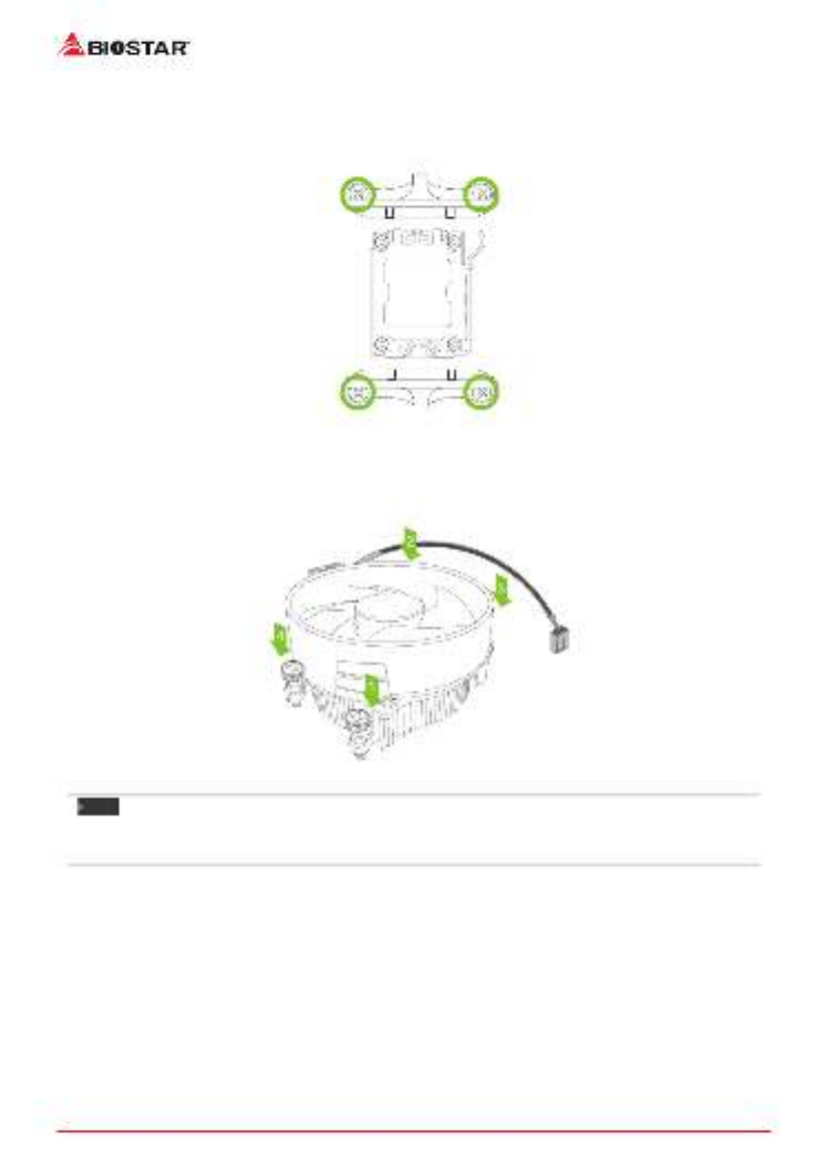
<TypeB>
Step 1: Remove the heatsink and fan assembly bracket on the motherboard and keep the
cooler backplane under the motherboard.
Step 2: Place the heatsink and fan assembly on top of the installed CPU and make sure that the
fan cable is closest to the CPU fan connector. Please refer diagram to the following screw into
the screw hole in the order shown.
Note
»
»Do not forget to connect the CPU fan connector.
»
»For proper installaon, please kindly refer to the installaon manual of your CPU heatsink.
Chapter 2: Hardware installaon | 13
A620MP-E PRO
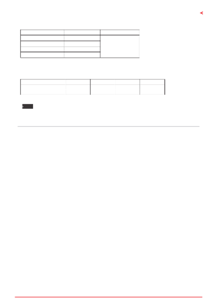
Memory Capacity
DIMM Socket Locaon DDR5 Module Total Memory Size
DDR5_A1 8GB/16GB/32GB
Max is 128GB.
DDR5_A2 8GB/16GB/32GB
DDR5_B1 8GB/16GB/32GB
DDR5_B2 8GB/16GB/32GB
Dual Channel Memory Installaon
Please refer to the following requirements to acvate Dual Channel funcon:
Install memory module of the same density in pairs, shown in the table.
Dual Channel Status DDR5_A1 DDR5_A2 DDR5_B1 DDR5_B2
Enabled X O X O
Enabled O O O O
(O means memory installed, X means memory not installed.)
Note
»
»When installing more than one memory module, we recommend to use the same brand and
capacity memory on this motherboard.
»
»When installing a single memory, we recommend that you install it in the DDR5_B2.
14 | Chapter 2: Hardware installaon
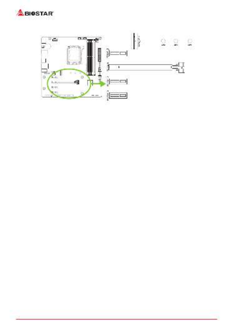
2.5 Expansion Slots
PCIEX16: PCI-Express Gen4 x16 Slots (x16 mode)
• PCI-Express 4.0 compliant.
• The maximum bandwidth of the PCIe slot is 64GB/s in total.
PCIEX1_1/ PCIEX1_2: PCI-Express Gen4 p14-x1 Slots (x1 mode)
• PCI-Express 4.0 compliant.
• The maximum bandwidth of the PCIe slot is 4GB/s in total.
PCIEX1_3: PCI-Express Gen3 p14-x1 Slots (x1 mode)
• PCI-Express 3.0 compliant.
• The maximum bandwidth of the PCIe slot is 2GB/s in total.
M2M_CPU: M.2 (M Key) Socket
• Supports M.2 Type 2242/ 2260/ 2280 SSD module
• Supports PCIe 4.0x 4 (64Gb/s) - NVMe SSD

Chapter 2: Hardware installaon | 15
A620MP-E PRO
M2E-WIFI: M.2 (E Key) Socket (M.2 (E Key) Wi-Fi card is not provided)
• Support M.2 (E Key) socket module.
• Supports WiFi/ Bluetooth module.
16 | Chapter 2: Hardware installaon
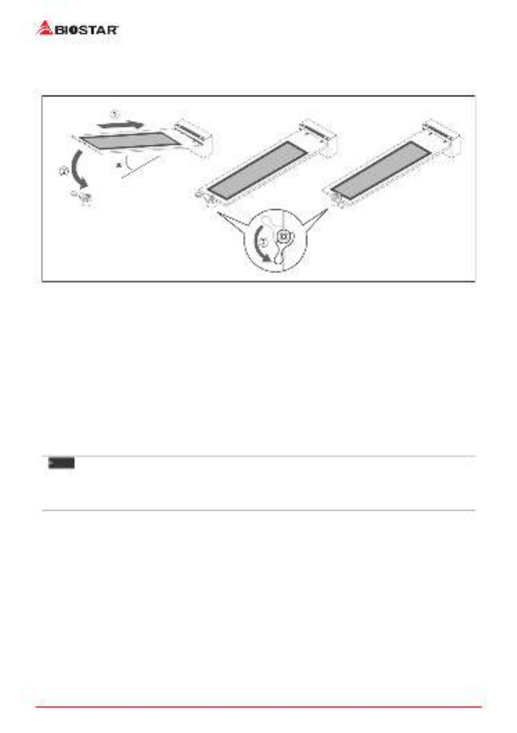
Install M.2 Latch
1. Please insert the M.2 SSD into the M.2 socket at 30 degree angle.
2. Check the M.2 latch and rotate it to x the M.2 SSD.
Install an Expansion Card
You can install your expansion card by following steps:
• Read the related expansion card’s instrucon document before install the expansion
card into the computer.
• Remove your computer’s chassis cover, screws and slot bracket from the computer.
• Place a card in the expansion slot and press down on the card unl it is completely
seated in the slot.
• Secure the card’s metal bracket to the chassis back panel with a screw. (This step is only
for installing a VGA card.).
• Replace your computer’s chassis cover.
• Power on the computer, if necessary, change BIOS sengs for the expansion card.
• Install related driver for the expansion card.
Note
»
»Please be note that you will need to use M2 type screwdriver if you want to install or uninstall the
screw. It is recommended not to use a screwdriver that does not meet the specicaons, otherwise
the screw may be damaged.
22 | Chapter 2: Hardware installaon
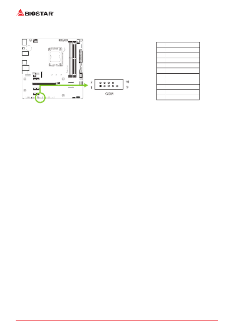
COM: Serial Port Connector
The motherboard has a serial port header for connecng RS-232 Port.
Pin Assignment
1 Carrier detect
2 Received data
3Transmied data
4 Data terminal ready
5Signal ground
6 Data set ready
7 Request to send
8 Clear to send
9 Ring indicator
10 Key
Produkt Specifikationer
| Mærke: | Biostar |
| Kategori: | Stikkontakt |
| Model: | A620MP-E PRO |
Har du brug for hjælp?
Hvis du har brug for hjælp til Biostar A620MP-E PRO stil et spørgsmål nedenfor, og andre brugere vil svare dig
Stikkontakt Biostar Manualer

1 September 2024
30 August 2024
30 August 2024
30 August 2024
30 August 2024
30 August 2024
30 August 2024
30 August 2024
30 August 2024
30 August 2024
Stikkontakt Manualer
- Stikkontakt Ikea
- Stikkontakt Denver
- Stikkontakt CyberPower
- Stikkontakt Hager
- Stikkontakt Silverline
- Stikkontakt Philips
- Stikkontakt Emos
- Stikkontakt Asus
- Stikkontakt Gigabyte
- Stikkontakt Biltema
- Stikkontakt AVM
- Stikkontakt Hama
- Stikkontakt Smartwares
- Stikkontakt Busch-Jaeger
- Stikkontakt Trotec
- Stikkontakt Vivanco
- Stikkontakt Osram
- Stikkontakt Gembird
- Stikkontakt Bose
- Stikkontakt Powerfix
- Stikkontakt Tripp Lite
- Stikkontakt Reer
- Stikkontakt Craftsman
- Stikkontakt Digitus
- Stikkontakt Gamma
- Stikkontakt Niceboy
- Stikkontakt Peerless-AV
- Stikkontakt Schneider
- Stikkontakt Bachmann
- Stikkontakt APC
- Stikkontakt Kathrein
- Stikkontakt Perel
- Stikkontakt JUNG
- Stikkontakt ORNO
- Stikkontakt ECS
- Stikkontakt Brennenstuhl
- Stikkontakt Hazet
- Stikkontakt Manhattan
- Stikkontakt SPC
- Stikkontakt LogiLink
- Stikkontakt Easy Home
- Stikkontakt Kramer
- Stikkontakt Lanberg
- Stikkontakt Anslut
- Stikkontakt Fibaro
- Stikkontakt Panduit
- Stikkontakt Eurolite
- Stikkontakt Vimar
- Stikkontakt Lenoxx
- Stikkontakt InLine
- Stikkontakt Crestron
- Stikkontakt Showtec
- Stikkontakt Kogan
- Stikkontakt Delta
- Stikkontakt Elektrobock
- Stikkontakt Konig & Meyer
- Stikkontakt Neutrik
- Stikkontakt Homematic IP
- Stikkontakt V-TAC
- Stikkontakt Legrand
- Stikkontakt Schwaiger
- Stikkontakt Heitronic
- Stikkontakt Savio
- Stikkontakt PCE
- Stikkontakt Bearware
- Stikkontakt Workzone
- Stikkontakt KlikaanKlikuit
- Stikkontakt Metz
- Stikkontakt AS - Schwabe
- Stikkontakt Duro
- Stikkontakt Gira
- Stikkontakt Peerless
- Stikkontakt Monoprice
- Stikkontakt Berker
- Stikkontakt Extron
- Stikkontakt Leviton
- Stikkontakt Ebode
- Stikkontakt InterBar
- Stikkontakt Pancontrol
- Stikkontakt Phoenix Contact
- Stikkontakt Metz Connect
- Stikkontakt DEHN
- Stikkontakt Omnilux
- Stikkontakt Atlona
- Stikkontakt Hoopzi
- Stikkontakt Hall Research
- Stikkontakt Crydom
- Stikkontakt Adam Hall
- Stikkontakt 360 Electrical
- Stikkontakt PS Audio
- Stikkontakt IOIO
Nyeste Stikkontakt Manualer
12 Januar 2025
10 Januar 2025

10 Januar 2025
3 Januar 2025
30 December 2025
29 December 2024
29 December 2024
29 December 2024
29 December 2024
29 December 2024