Bosch AutoDome VG4161CCE Manual
Bosch
Overvågningskamera
AutoDome VG4161CCE
Læs nedenfor 📖 manual på dansk for Bosch AutoDome VG4161CCE (139 sider) i kategorien Overvågningskamera. Denne guide var nyttig for 21 personer og blev bedømt med 4.5 stjerner i gennemsnit af 2 brugere
Side 1/139

VG4 Modular Camera System
VG4-200 | VG4-300 | VG4-500i
en User’s Manual


VG4 Modular Camera System Table of Contents | en 3
Bosch Security Systems, Inc. User’s Manual F.01U.133.268 | 6.0 | 2010.03
Table of Contents
1 Getting Started 7
1.1 Powering On 7
1.2 Establishing AutoDome Control 7
1.2.1 Basic Keyboard Operation 7
1.2.2 Keyboard Commands 8
1.3 Setting the Camera Address 8
1.3.1 FastAddress 9
1.4 Setting Passwords 9
1.4.1 Special Passwords 9
2 On-Screen Display Menu Navigation 11
2.1 Setup Menu 11
2.2 Camera Setup Menu 12
2.3 Lens Setup 14
2.4 PTZ Setup Menu 16
2.5 Display Setup Menu 17
2.6 Communication Setup Menu 19
2.7 Alarm I/O Setup 20
2.8 Rule Setup Menu 23
2.9 Language Menu 24
2.10 Advanced Feature Setup Menu (available with Series 500i only) 25
2.11 Diagnostics Menu 26
2.11.1 Alarm Status Submenu 28
3 Common AutoDome User Commands (unlocked) 30
3.1 Setting AutoPan Mode 30
3.2 Setting Preset Shots 30
3.3 Specifying a Shot or a Sector Title 30
3.4 Configuring Preposition Tours 31
3.5 Programming the Inactivity Operation 31
3.6 Recording Tours (300 and 500i Series only) 32
4 Alternative Control Protocols 33
4.1 Setting FastAddress with Alternative Protocols 33
4.1.1 Using an American Dynamics Controller 33
4.1.2 Using a Pelco Controller 35
4.2 Pelco Protocol Mode 36
4.2.1 Hardware Configuration 36
4.2.2 Pelco Keyboard Commands 37
4.2.3 Pelco Keyboard Commands 37
4.2.4 Special Preset Commands 38

4en | Table of Contents VG4 Modular Camera System
F.01U.133.268 | 6.0 | 2010.03 User’s Manual Bosch Security Systems, Inc.
5 Pelco On-Screen Menus 39
5.1 Setup Menu 39
5.1.1 Command Lock (locked) 40
5.1.2 Bosch Menu (locked) 40
5.1.3 PTZ Setup (unlocked) 41
5.1.4 Other Menus 42
6 Keyboard Commands by Number 43
7 Advanced Features 46
7.1 Alarm Rules (300 and 500i Series Only) 46
7.1.1 Controlling Alarm Rules 46
7.1.2 Alarm Rule Examples 46
7.2 AutoTrack Operation (500i Series Only) 50
7.2.1 AutoTrack Settings and Recommendations 50
7.2.2 AutoTrack Optimization 51
7.3 Virtual Masking (500i Series Only) 52
7.4 Privacy Masking (300 and 500i Series Only) 52
7.5 Motion Detection with Region of Interest (500i Series Only)
(Preset positions 90 through 99)53
7.6 Image Stabilization (500i Series Only) 53
7.7 Pre-position Tour 53
8 Using the IP AutoDome 55
8.1 Overview of Features 55
8.2 System Requirements 55
8.3 Connecting the IP AutoDome to the PC 56
8.4 Configuring the IP AutoDome Camera 57
8.5 Installing the Required Software 57
8.5.1 Changing the Network Settings 58
8.6 The LIVEPAGE 60
8.6.1 Entering a Keyboard Control Command 62
8.7 Saving Snapshots 64
8.8 Recording Video Sequences 64
8.9 Running Recording Program 64
9 VG4 Audio Connections 65
9.1 Audio Line Input Specifications 65
9.1.1 Wire Specifications 65
9.1.2 Connections 65
9.1.3 Activating Audio Reception 65
9.1.4 Enabling Audio Transmission 66
9.1.5 Configuring Gain (optional) 67

VG4 Modular Camera System Table of Contents | en 5
Bosch Security Systems, Inc. User’s Manual F.01U.133.268 | 6.0 | 2010.03
10 Configuring the IP AutoDome 68
10.1 Basic Mode: Device Access 68
10.2 Basic Mode: Date/Time 69
10.3 Basic Mode: Network 70
10.4 Basic Mode: Encoder Profile 71
10.5 Basic Mode: Audio 71
10.6 Basic Mode: Recording 71
10.7 Basic Mode: System Overview 72
10.8 Advanced Mode: Identification 72
10.9 Advanced Mode: Password 73
10.10 Advanced Mode: Date/Time 73
10.11 Advanced Mode: Display Stamping 74
10.12 Advanced Mode: Appearance 75
10.13 Advanced Mode: LIVEPAGE Functions 76
10.14 Advanced Mode: Logging 77
10.15 Advanced Mode: Picture Settings 77
10.16 Advanced Mode: Encoder Profile 78
10.17 Advanced Mode: Encoder Streams 80
10.18 Advanced Mode: Audio 80
10.19 Advanced Mode: Camera Options 81
10.20 Camera Settings Group 1 81
10.21 Camera Settings Group 2 82
10.22 Camera Settings Group 3 82
10.23 Advanced Mode: Lens 82
10.24 Lens Settings Group 1 82
10.25 Lens Settings Group 2 83
10.26 Advanced Mode: PTZ 83
10.27 PTZ Settings Group 1 83
10.28 PTZ Settings Group 2 84
10.29 Advanced Mode: Display 85
10.30 Display Settings Group 1 85
10.31 Display Settings Group 2 85
10.32 Display Settings Group 3 86
10.33 Advanced Mode: Alarm 86
10.34 Input Options 86
10.35 Output Options 87
10.36 Alarm Rules 88
10.37 Miscellaneous 93
10.38 Logs 94
10.39 Advanced Mode: Storage Management 94
10.40 Advanced Mode: Recording Profiles 95
10.41 Advanced Mode: Retention Time 97
10.42 Advanced Mode: Recording Scheduler 97
10.43 Advanced Mode: Recording Status 98
10.44 Advanced Mode: Alarm Connections 99
10.45 Advanced Mode: VCA 101
10.46 Advanced Mode: VCA Profiles 101
10.47 Advanced Mode: VCA Scheduled 105
10.48 Advanced Mode: VCA Event triggered 106

6en | Table of Contents VG4 Modular Camera System
F.01U.133.268 | 6.0 | 2010.03 User’s Manual Bosch Security Systems, Inc.
10.49 Advanced Mode: Audio Alarm 107
10.50 Advanced Mode: Alarm E-Mail 107
10.51 Advanced Mode: Alarm Task Editor 108
10.52 Advanced Mode: Network 110
10.53 Advanced Mode: Advanced 112
10.54 Advanced Mode: Multicasting 113
10.55 Advanced Mode: JPEG Posting 114
10.56 Advanced Mode: Encryption 115
10.57 Advanced Mode: Maintenance 115
10.58 Advanced Mode: Licenses 116
10.59 Advanced Mode: System Overview 116
11 Troubleshooting Guide 117
11.1 VG4 AutoDome Operation and Control 117
11.2 VG4 IP AutoDome Video and Control 120
11.3 VG4 IP AutoDome Audio 121
12 User Command Table 125
A Appendix: FastAddress Conversions 127
Index 128

VG4 Modular Camera System Getting Started | en 7
Bosch Security Systems, Inc. User’s Manual F.01U.133.268 | 6.0 | 2010.03
1 Getting Started
Install and wire the AutoDome according to the Bosch AutoDome Modular Camera System
Installation Manual. A typical system includes a keyboard, matrix switcher, monitor, and
appropriate wiring connections. Please refer to the individual product manuals for complete
installation and setup instructions for each of the system components.
1.1 Powering On
When you turn the AutoDome power on there is a ten (10) second pause before the dome
starts its homing phase. During the homing phase the camera pans left and right and tilts up
and down. It also adjusts the lens focus. The entire homing phase lasts approximately 40
seconds and ends with a splash screen.
Figure 1.1 Sample VG4 Startup Splash Screen
The splash screen displays the type of AutoDome, the camera installed, the firmware levels for
various files, and the current IP address (if the AutoDome contains the IP Communications
module). The (P) to the right of the AutoDome series indicates that the AutoDome contains
the optional modules for maintaining internal pressure.
1.2 Establishing AutoDome Control
The most common ways to interface with the AutoDome are:
– Using a keyboard and on-screen display (OSD) menus. This method is the most common
and is covered in this manual.
– Using the AutoDome Configuration Tool software running on a PC with Bilinx or the RS-
232/485 communication protocol. Refer to the CTFID User Manual for instructions.
– Using a PC-based graphical user interface (GUI) such as the Bosch DiBos 8 software.
Refer to the DiBos 8 User Guide for instructions.
– Using the Bosch IP Web interface included with the IP Communications Module.
Bosch Security Sys. AutoDome(r)
500 Series(P)
Day/Night 26X
SC Boot
FPGA
Lang. Table
VCA_boot
IP-Panel
IP Address
Subnet Mask
No Heater
FastAddress: Not Set
1.10.00.02/1.07.58.02
2.00.00.00
1.05.00.01
1.13.01.05
1.00.00.01
1.02.00.01
4.10.50.13
10. 25.118.111
255.255.248. 0
8en | Getting Started VG4 Modular Camera System
F.01U.133.268 | 6.0 | 2010.03 User’s Manual Bosch Security Systems, Inc.
1.2.1 Basic Keyboard Operation
The following tables summarize the basic operations for a standard keyboard and the
functions available to control an AutoDome camera.
Table 1.1 Typical Keyboard Functions
Table 1.2 Typical Keyboard Controls for an AutoDome Camera
1.2.2 Keyboard Commands
Keyboard control commands are composed of a sequence of three (3) inputs with the
following convention: 1) a Function key + 2) a Command number key(s) + 3) the Enter key.
– Depending on the type of keyboard, the control function keys are labeled:
ON or AUX ON
OFF or AUX OFF
SET or SET SHOT
SHOT or SHOW SHOT
– Command numbers range from 1 to 999. See Section 6 Keyboard Commands by Number,
page 43 for a complete list of keyboard commands.
– The Enter key can also be labeled with the 8 symbol.
For example, the keyboard command to make the AutoDome pan 360º continuously is:
ON-1-ENTER(press the ON key, then press the number 1 key, and then press ENTER.)
Typical Keyboard
Features
Usage
Function Keys Selects a specific control setting.
Number Keys Inputs a number from 0 to 9.
Camera Key Selects a camera number.
Enter Key Inputs a selection.
Focus Key Sets the lens focus or makes a menu selection in OSD mode.
Iris Key Sets the lens iris setting or makes a menu selection in OSD mode.
Key LEDs Indicates an active key.
LCD Displays the current status.
Joystick Controls a pan/tilt/zoom (PTZ) AutoDome camera.
Dome Operation How to control
To Pan Side to Side Move the joystick left or right.
To Tilt Up and Down Move the joystick forward and back.
To Zoom In Twist the joystick clockwise.
To Zoom Out Twist the joystick counterclockwise.
NOTICE! The convention used for control key commands in this manual is ON, OFF, SET, and
SHOT. Refer to your keyboard manual for the key naming conventions.

VG4 Modular Camera System Getting Started | en 9
Bosch Security Systems, Inc. User’s Manual F.01U.133.268 | 6.0 | 2010.03
1.3 Setting the Camera Address
Once the AutoDome power is turned on and homing is complete, you must set the camera
address. You may also want to assign a password and customize some of the AutoDome
default settings.
1.3.1 FastAddress
FastAddress is an AutoDome feature that allows you to set or change a camera address using
the keyboard and on-screen menus.
There are three (3) FastAddress commands:
–ON-999-ENTER: Displays and programs all cameras without an address in the system.
–ON-998-ENTER: Displays and programs all cameras with or without an address in the
system.
–ON-997-ENTER: Displays the current address status of all cameras in the system
simultaneously.
To set an address for a camera without an address:
1. Select the camera number you want to FastAddress. The system displays the camera
number on the keyboard and the image on the corresponding monitor.
2. Press #-ENTER (where # is the camera number without an address).
3. Press ON-999-ENTER to invoke an on-screen display of cameras on the system without
an address.
4. Follow the on-screen instructions. You receive an on-screen confirmation when the
FastAddress is complete.
To change or clear an address for a camera with an address:
1. Select the camera number you want to FastAddress. The system displays the camera
number on the keyboard and the image on the corresponding monitor.
2. Press #-ENTER (where # is the camera number with an address).
3. Press ON-998-ENTER to invoke an on-screen display of all cameras on the system, with or
without an address.
4. Follow the on screen instructions. You receive an on-screen confirmation when the
FastAddress is complete.
NOTICE! You do not need to set a camera address if using Bilinx or Ethernet communication.
See the AutoDome Modular Camera System Installation Manual to configure an AutoDome for
Bilinx or Ethernet operation.
NOTICE! If a keyboard is set to a camera number that already has an address, that camera
also responds to this command.
NOTICE! FastAddress is stored in nonvolatile memory and does not change if the power is
turned off or if the default settings are restored.

10 en | Getting Started VG4 Modular Camera System
F.01U.133.268 | 6.0 | 2010.03 User’s Manual Bosch Security Systems, Inc.
1.4 Setting Passwords
Passwords are used to control access to locked command menus. Unlocked commands are
available to all users. Passwords are four (4) digits in length.
1.4.1 Special Passwords
To set or change a password (locked command):
1. Press OFF-90-ENTER to turn off the command lock.
2. Press SET-802-ENTER to access the password menu.
3. Tilt the joystick up or down to choose a number. Tilt the joystick right to move to the next
number position.
4. Follow the on-screen instructions and save the password. You receive an on-screen
confirmation.
Password Security Level
0000 (default) Enables security and requires a user to enter the unlock command
OFF-90-ENTER before invoking a locked command.
9999 Disables all security and allows all users to access locked commands.

VG4 Modular Camera System On-Screen Display Menu Navigation | en 11
Bosch Security Systems, Inc. User’s Manual F.01U.133.268 | 6.0 | 2010.03
2 On-Screen Display Menu Navigation
The AutoDome is programmed through the on-screen display (OSD) menus. To access the
OSD menus, you must open the main Setup Menu.
Menu items marked with an asterisk (*) are default settings, unless otherwise noted.
2.1 Setup Menu
The main Setup Menu provides access to all programmable AutoDome settings. It is a locked
menu that requires the user to turn off the command lock.
To open the main Setup Menu (locked command):
1. Press OFF-90-ENTER to turn off the command lock.
2. Press ON-46-ENTER to access the Main Menu.
3. Use the joystick to highlight a menu item.
4. Press Focus/Iris to open a menu.
5. Follow the on-screen instructions.
Setup Menu Choices:
NOTICE! After a period of 4.5 minutes of inactivity, a menu times-out and exits without
warning. Some unsaved settings in the current menu can be lost.
NOTICE! The AutoDome displays only those menus applicable to the AutoDome Series
configuration. Use the joystick to navigate through the menu and the Focus/Iris keys to make
a selection.
Setup Menu
Exit...
Camera Setup
Lens Setup
PTZ Setup
Display Setup
Communication Setup
Alarm Setup
Language
Advanced
Diagnostics
Focus / Iris: Select
Menu Description
Exit Exits the menu.
Camera Setup Accesses adjustable camera settings such as: white balance, gain,
sharpness, sync, line lock, backlight, shutter, and night mode.
Lens Setup Accesses adjustable lens settings such as: focus, iris, zoom speed, and
digital zoom.
PTZ Setup Accesses adjustable pan/tilt/zoom (PTZ) settings such as: Autopan, tours,
PTZ speed, inactivity period, AutoPivot, and tilt limits.

12 en | On-Screen Display Menu Navigation VG4 Modular Camera System
F.01U.133.268 | 6.0 | 2010.03 User’s Manual Bosch Security Systems, Inc.
2.2 Camera Setup Menu
The Camera Setup Menu provides access to camera settings that can be changed or
customized. Menu items marked with an asterisk (*) are the default settings.
Display Setup Accesses adjustable display settings such as: OSD, sector blanking, and
privacy masking.
Communication
Setup
Accesses communication settings such as: AutoBaud and Bilinx.
Alarm Setup Accesses the alarm settings such as: inputs, outputs, and rules (not
available with 200 Series models).
Language Displays the language.
Advanced Accesses the advanced features menu including Stabilization, AutoTrack
Sensitivity, Camera Height, and Virtual Masking (only available on 500i
Series models).
Diagnostics Displays the status of diagnostic events.
Menu Description
NOTICE! To select the Exit Menu item from anywhere in the current menu, use the Zoom
command.
Camera Setup
Exit...
* White Bal: EXT ATW
* Gain Control: AUTO
* Max. Gain Level: 6 (4**)
* Sharpness 12
* Synch Mode: Internal
* Line Lock Delay: 0
* Backlight Comp: OFF
* WDR OFF
* Shutter Mode: Auto SensUP
* Shutter: 1/60
* Auto SensUP Max: 15x
* Night Mode: AUTO
* Night Mode Color: OFF
* Night Mode Threshold: 55
* Pre-Comp 1
Restore Defaults...
* = Factory Setting
** = WDR camera only
Focus / Iris: Select

VG4 Modular Camera System On-Screen Display Menu Navigation | en 13
Bosch Security Systems, Inc. User’s Manual F.01U.133.268 | 6.0 | 2010.03
Camera Setup Menu Choices:
Menu Description Sub-menu / Description Default
Setting
Exit Exits the menu.
White Balance Maintains proper color
reproduction as the
color temperature of a
scene changes. For
example, from daylight
to fluorescent lighting.
Extended ATW: Adjusts camera
color using extended range.
ATW: Adjusts camera color
constantly.
Indoor W.B.: Optimizes camera
color for typical indoor conditions.
Outdoor W.B.: Optimizes camera
color for typical outdoor
conditions.
AWB Hold: Sets the camera's
color settings for the current
scene.
Manual: Allows a user to adjust
the Red and Blue gain.
Sliding scale: – (1 to 100) +
Extended
ATW
Gain Control Electronically brightens
darker scenes which may
cause graininess in low
light scenes.
Auto or OFF AUTO
Max. Gain Level Adjusts the maximum
gain level that the gain
control adjusts to when
set to AUTO.
Sliding scale: – (1 to 6) +
(1=8db, 2=12db, 3=16db, 4=20db,
5=24db, 6=28db)
6
(4 for 36X
camera)
Sharpness Adjusts the sharpness
level of the picture.
Sliding scale: – (1 to 16) + 12
Synch Mode Sets the type of
synchronization mode
for the camera.
INTERNAL: Synchronizes camera
to an internal crystal. This choice
is recommended if there is noise
on the power line.
LINE LOCK: Synchronizes camera
to AC power. This choice
eliminates picture roll in multi-
camera systems.
INTERNAL
Line Lock Delay Optimizes the LINE
LOCK mode to eliminate
picture roll in multiphase
power applications.
Sliding scale: – (0º to 359º) + 0º
Backlight Comp Improves image quality
when the background
illumination level is high.
ON or OFF OFF
WDR Turns the wide dynamic
range feature on or off.
ON or OFF OFF
Shutter Mode: Turns Auto SensUP on or
off.
Auto SensUP or OFF Auto
SensUP

14 en | On-Screen Display Menu Navigation VG4 Modular Camera System
F.01U.133.268 | 6.0 | 2010.03 User’s Manual Bosch Security Systems, Inc.
Shutter Adjusts the electronic
shutter speed (AES).
Sliding scale:
– (60 at extreme left to 1/10000) +
1/60 sec.
(NTSC) or
1/50 sec.
(PAL)
Auto SensUP
Max.
Sets the limit for
sensitivity when the
shutter speed is set to
Auto SensUP.
15x, 7.5x, 4x, or 2x 15x
Night Mode
(Day/Night
models only)
Selects night mode (B/
W) to enhance lighting in
low light scenes.
ON, OFF, or AUTO AUTO
Night Mode
Color
(Day/Night
models only)
Determines if color
processing remains in
effect while in night
mode.
ON or OFF OFF
Night Mode
Threshold
(Day/Night
models only)
Adjusts the level of light
at which the camera
automatically switches
out of night mode (B/W)
operation.
Sliding scale: –(10 to 55)+
(in increments of 5)
10 is earlier, 55 is later
55
Pre-Comp
(not applicable
with IP
AutoDome
models)
Amplifies the video gain
to compensate for long
distance cable runs.
Sliding scale: –(1 to 10)+ 1
Restore
Defaults
Restores all default
settings for this menu
only.
Menu Description Sub-menu / Description Default
Setting

VG4 Modular Camera System On-Screen Display Menu Navigation | en 15
Bosch Security Systems, Inc. User’s Manual F.01U.133.268 | 6.0 | 2010.03
2.3 Lens Setup
The Lens Setup Menu provides access to lens settings that can be changed or customized.
Menu items marked with an asterisk (*) are the default settings.
Lens Setup Menu Choices:
Lens Setup
Exit...
* Auto Focus: SPOT
* Auto Iris: CONSTANT
* Auto Iris Level: 8
* Focus Speed: 2
* Iris Speed: 5
* Max Zoom Speed: FAST
* Digital Zoom: ON
Restore Defaults
* = Factory Setting
Focus / Iris: Select
Menu Description Sub-menu / Description Default
Setting
Exit Saves and exits the
menu.
Auto Focus Automatically
focuses on the
subject in the center
of the screen.
CONSTANT: Auto Focus is always active,
even while the camera is moving.
MANUAL: Auto Focus is inactive; manual
focus must be used.
SPOT: The camera activates Auto Focus
after the camera stops movement. Once
focused, Auto Focus is inactive until the
camera moves again.
SPOT
Auto Iris Automatically adjusts
to varying light
conditions.
MANUAL: Iris must be adjusted manually.
CONSTANT: Auto Iris is constantly active.
CONSTANT
Auto Iris
Level
Reduces the
camera's iris level for
proper exposure.
Sliding scale: – (1 to 15) + 8
Focus
Speed
Adjusts the manual
focus speed.
Sliding scale: – (1 to 8) + 2
Iris Speed Adjusts the manual
iris speed.
Sliding scale: – (1 to 10) + 5
Max. Zoom
Speed
Adjusts the manual
zoom speed.
SLOW, MEDIUM, or FAST FAST

16 en | On-Screen Display Menu Navigation VG4 Modular Camera System
F.01U.133.268 | 6.0 | 2010.03 User’s Manual Bosch Security Systems, Inc.
2.4 PTZ Setup Menu
The PTZ Menu provides access to pan/tilt/zoom settings that can be changed or customized.
Menu items marked with an asterisk (*) are the default settings.
PTZ Menu Choices:
Digital
Zoom (not
available
with 200
Series
models)
Enables digital zoom. OFF or ON ON
Restore
Defaults
Restores all default
settings for this
menu.
Menu Description Sub-menu / Description Default
Setting
PTZ Setup
Exit...
* Autopan: 30 deg/sec
* Tour 1 Period: 5 sec
* Tour 2 Period: 5 sec
* PTZ Fixed Speed: 4
* Inactivity: OFF
* Inact. Period 2 min
* AutoPivot: ON
* AutoDome Orientation NORMAL
* Freeze Frame on Preposition ON
Tilt Up Limit...
Restore Defaults
* = Factory Setting
Focus / Iris: Select
Menu Description Sub-menu / Description Default
Setting
Exit Exits the menu.
AutoPan Adjusts speed of camera
during AutoPan and
AutoScan.
Sliding scale:
– (1º/sec. to 60º/sec.) +
30º/sec.
Tour 1 Period Changes dwell time
between presets during
the tour.
Sliding scale: – (3 sec. to 10 min.)
+
5 sec.
Tour 2 Period
(not available
with 200 Series
models)
Changes dwell time
between presets during
the tour.
Sliding scale: – (3 sec. to 10 min.)
+
5 sec.

VG4 Modular Camera System On-Screen Display Menu Navigation | en 17
Bosch Security Systems, Inc. User’s Manual F.01U.133.268 | 6.0 | 2010.03
PTZ Fixed
Speed
Sets pan and tilt speed
when controlled by a
fixed speed controller.
Sliding scale: – (1 to 15) + 4
Inactivity Selects the mode that an
AutoDome reverts to after
the period of inactivity set
in the inactivity period.
Scene 1: Returns to Preset 1.
Prev Aux: Returns to previous
activity, such as Aux commands 1,
2, 7, 8, 50, or 52.
OFF: Remains on the current scene
indefinitely.
OFF
Inactivity
Period
Sets the time period of
inactivity before the
above action occurs.
Sliding scale:
– (3 sec. to 10 min.) +
2 min.
AutoPivot Automatically rotates the
camera 180º when
following a subject
traveling directly beneath
the camera.
OFF or ON ON
AutoDome
Orientation
(not available
with 18x color
camera)
Automatically rotates the
video 180º.
INVERTED or NORMAL NORMAL
Freeze Frame
On Preposition
(not available
with 18x color
camera)
Holds a preposition video
frame while moving to
another preposition.
OFF or ON ON
Tilt Up Limit... Sets the upper tilt limit of
the camera.
Use joystick to move to a scene.
Restore
Defaults
Restores the default
setting for this menu only.
Menu Description Sub-menu / Description Default
Setting

VG4 Modular Camera System On-Screen Display Menu Navigation | en 19
Bosch Security Systems, Inc. User’s Manual F.01U.133.268 | 6.0 | 2010.03
2.6 Communication Setup Menu
The Communication Setup Menu provides access to baud rate and Bilinx control settings.
Menu items marked with an asterisk (*) are the default settings.
Privacy
Masking
(not
available
with 200
Series
models)
Allows masking of
sensitive areas. Up to 24
privacy masks are
available, with a
maximum limit of eight
(8) to a scene.
Exit: Saves and exits menu.
Mask: 1 to 24 masking areas. Follow the
on-screen instructions to set a mask.
See Section 7.1 Alarm Rules (300 and
500i Series Only), page 46.
Restore Defaults: Restores the default
settings for this menu only.
Edit
Sector
Title
Allows editing existing
Sector (Zone) Titles
Select a sector title to access the
character palette. See
Section 3.3 Specifying a Shot or a Sector
Title, page 30, for instructions.
Edit
Scene
Title
Allows editing existing
Scene (Shot) Titles
Select a scene title, then choose a menu
option:
–Edit Scene Title to access the
character palette. See
Section 3.3 Specifying a Shot or a
Sector Title, page 30, for
instructions.
–Clear Scene to delete the selected
scene title.
Restore
Defaults
Restores the default
setting for this menu only.
Menu Description Sub-menu / Description Default
Setting
Communication Setup
Exit...
* AutoBaud: ON
* Baud Rate 9600
* Bilinx: ON
Restore Defaults...
* = Factory Setting
Focus / Iris: Select

20 en | On-Screen Display Menu Navigation VG4 Modular Camera System
F.01U.133.268 | 6.0 | 2010.03 User’s Manual Bosch Security Systems, Inc.
Communication Setup Menu Choices:
2.7 Alarm I/O Setup
The Alarm Setup Menu provides access to the Alarm I/O Setup Menu to establish the alarm
inputs and outputs and to configure alarm rules.
Menu items marked with the ‡ symbol are available only with VG4 Pressure Domes.
Menu Description Sub-menu / Description Default
Setting
Exit Saves and exits the menu.
AutoBaud Turns AutoBaud detection on. Toggles ON or OFF.
ON automatically accepts baud
rates from 2400 to 57600.
(Note: If stepping from 2400 to
57600 baud, you must first set the
controller to 19200 for AutoBaud
to detect the higher baud rate.)
ON
Baud Rate Manually sets the baud rate when
AutoBaud is set to OFF.
Choices are 2400, 4800, 9600,
19200, 38400, and 57600. Then
follow the OSD to confirm the
selection.
9600
Bilinx Turns on Bilinx control
communication.
(Only available when not
connected to a Bilinx data
interface unit.)
Toggles ON or OFF. ON
NOTICE! Bilinx protocol is not available with IP cameras.
Alarm I/O Setup Inputs Setup
Exit... Exit...
Inputs Setup... 1. Alarm Input 1 N.C.S.
Physical
Input 1-7
Outputs Setup... 2. Alarm Input 2 N.O.S.
Rule Setup... 3. Alarm Input 3 N.O.
Restore Defaults... 4. Alarm Input 4 N.C.
5. Alarm Input 5 N.O.
6. Alarm Input 6 N.C.
7. Alarm Input 7 N.O.
8. Low Pressure‡
9. NONE
Physical
Output 9-12
10. NONE
11. NONE
12. NONE
Focus / Iris: Select Type
Focus / Iris: Select Right / Left: Select Mode

VG4 Modular Camera System On-Screen Display Menu Navigation | en 21
Bosch Security Systems, Inc. User’s Manual F.01U.133.268 | 6.0 | 2010.03
Alarm Setup Menu Choices:
Menu Description Sub-menu / Description Default
Setting
Exit Saves and exits the menu.
Inputs
Setup
Defines physical inputs or
events and commands that can
be used in a rule. There are
twelve (12) alarm inputs
available.
Inputs 1-7 Defines the type of physical
input.
N.O.: Normally open dry contact.
N.C.: Normally closed dry contact.
N.C.S.: Normally closed supervised
contact.
N.O.S.: Normally open supervised
contact.
N.O.
Low
Pressure
A fixed, physical alarm input
that detects a drop in internal
pressure for the VG4 Pressure
Dome.
Inputs 8-12 Defines input commands that
can be used in a rule.
Command inputs can also be
customized by using non-
assigned keyboard command
numbers.
NONE: No command defined.
Aux On: Responds to a standard or
custom keyboard ON (1-99)
command.
Aux Off: Responds to a standard or
custom keyboard OFF (1-99)
command.
Shot: Responds to a Preset shot or
scene from 1-99. (200 Series 1-64).
AutoTrack: Triggers an alarm when
set to ON. (Available with 500i Series
only).
Motion Detection: Triggers an alarm
when set to ON. (Available with 500i
Series only).
NONE
NOTICE! Alarm inputs 1 and 2 provide tamper detection, if programmed as supervised, for
breaks or shorts in an alarm circuit. See the AutoDome Modular Camera System Installation
Manual for wiring instructions.

22 en | On-Screen Display Menu Navigation VG4 Modular Camera System
F.01U.133.268 | 6.0 | 2010.03 User’s Manual Bosch Security Systems, Inc.
Outputs Setup Menu
Outputs Setup Menu Choices
Outputs Setup...
Exit...
1. Alarm Output 1 N.O. 1-4
Physical
2. Alarm Output 2 N.O.
3. Alarm Output 3 N.O. Outputs
4. Alarm Relay N.O.
5. NONE
5-12
Command
Outputs
6. Aux On 1
7. Aux Off 8
8. Shot 99
9. OSD
10. Transmit
11. NONE
12. NONE
Focus / Iris: Select Type
Right / Left: Select Mode
Menu Description Sub-menu / Description Default
Setting
Exit Saves and exits the
menu.
Outputs Setup Defines physical outputs
and keyboard commands
for use in a rule.
Outputs 1-3 Defines a physical
output.
N.O.: Normally open circuit
N.C.: Normally closed circuit
N.O.
Alarm Relay A fixed output available
for use in a rule.
Outputs 5-12 Defines a command
output for use in a rule.
Aux On: A keyboard ON
command.
Aux Off: A keyboard OFF
command.
Shot: Recalls a preset shot.
OSD: An on screen display.
Transmit: Transmits a message
back to the head end (available
with RS-232 serial connections,
Bilinx, and IP AutoDome models).
AutoTrack: Turns AutoTrack on
or off as an output. (Available
with 500i Series only).
NONE: No command defined.
NONE
Outputs 5
and 6 set to
OSD and
Shot 1
VG4 Modular Camera System On-Screen Display Menu Navigation | en 23
Bosch Security Systems, Inc. User’s Manual F.01U.133.268 | 6.0 | 2010.03
2.8 Rule Setup Menu
The Rule Setup Menu shows the status of the rules and lets you add new rules or modify an
existing rule. The default setting is Empty.
Menu items marked with the ‡ symbol are available only with VG4 Pressure Domes.
Rule Setup Menu Choices
Selecting a Rule number provides access to its configuration menu. The Rule # Menu allows
you to configure a rule from previously defined alarm inputs and outputs. Once an alarm is
configured with valid inputs and outputs, it can be turned on or off (enabled or disabled)
through its configuration menu.
NOTICE! You can program a total of twelve rules. You must define the inputs and outputs
before you program a rule. See Section 2.7 Alarm I/O Setup, page 20, to configure alarm inputs
and outputs.
Rule Setup... Rule 1
Exit... Exit...
1. Rule 1 Enabled Enabled YES
2. Rule 2 Disabled Input:
3. Rule 3 Invalid Low Pressure‡
4. Rule 4 Empty NONE
5. Rule 5 Empty NONE
6. Rule 6 Empty NONE
7. Rule 7 Empty Output:
8. Rule 8 Empty OSD
9. Rule 9 Empty Shot 2
10. Rule 10 Empty Alarm Relay 2 sec
11. Rule 11 Empty NONE
12. Rule 12 Empty
4. Rule 4 Empty
Right / Left: Select Period Time
Focus / Iris: Select Focus / Iris: Select Type
Menu Description Sub-menu / Description Default
Setting
Exit Saves and exits the
menu.
Rule 1-12 Displays the status
of a rule on the
right side of the
menu. There are
four (4) possible
rule statuses.
Enabled: The rule inputs and outputs are
properly defined and the rule is turned on.
Disabled: The rule inputs and outputs are
defined but the rule is turned off.
Invalid: The rule has a missing or invalid
input or output.
Empty: The rule has no inputs or outputs
defined.
Empty

24 en | On-Screen Display Menu Navigation VG4 Modular Camera System
F.01U.133.268 | 6.0 | 2010.03 User’s Manual Bosch Security Systems, Inc.
Rule # Choices:
Menu Description Sub-menu / Description Default
Setting
Exit Saves and exits the menu.
Enabled Turns the rule on or off after
its inputs and outputs have
been defined.
YES to enable or NO NO to disable
Input Toggles through a list of valid
inputs set in the Alarm I/O
Setup > Inputs Setup Menu
that define the rule's inputs.
A rule can have up to four (4)
inputs.
Alarm Inputs 1 – 7 and any
additional inputs which were set in
the Inputs Setup Menu, including
Aux On/Off (1-99), Shot, Low
Pressure‡ and NONE.
NONE
Output Toggles through a list of valid
outputs set in the Alarm I/O
Setup > Outputs Setup
Menu that defines a rule's
outputs.
Alarm Outputs 1 – 3 and any
additional outputs set in the
Outputs Setup Menu including:
Alarm Relay, Aux On/Off (1-99),
Shot, OSD, Transmit, and NONE.
Some outputs, such as Alarm
Outputs 1-3, Alarm Relay, and Aux
On/Off can be set to be active for a
specific duration of time as follows:
Seconds: 1-5, 10, 15, or 30
Minutes: 1-5 or 10
Latched: The alarm stays active
until acknowledged.
Follows: The alarm follows the
alarm rule.
NONE
NOTICE! You can include up to four (4) Input and Output events in a single rule. Each input
and output, however, must be true for the alarm's rule to be valid and enabled.

VG4 Modular Camera System On-Screen Display Menu Navigation | en 25
Bosch Security Systems, Inc. User’s Manual F.01U.133.268 | 6.0 | 2010.03
2.9 Language Menu
The Language Menu provides access to a list of languages to display the on-screen menus.
Language Menu Choices:
2.10 Advanced Feature Setup Menu (available with Series 500i only)
The Advanced Menu provides access to the Advanced Features Setup menus such as image
Stabilization, AutoTrack Sensitivity and Virtual Masking. Menu items marked with an asterisk
(*) are the default settings.
Language
Exit...
English
Spanish
French
German
Portuguese
Polish
Italian
Dutch
Focus / Iris: Save and Exit
Menu Description Default
Setting
Exit Saves and exits the menu.
Choose a language Select a language in which the system displays the on-
screen menus.
Advanced Feature Setup
Exit...
* Stabilization OFF
* AutoTrack Sensitivity Auto
AutoTrack TImeout OFF
AutoTrack TImeout Period 5 min
* Camera Height: 12
Virtual Masking...
Restore Defaults...
Focus / Iris: Save and Exit

26 en | On-Screen Display Menu Navigation VG4 Modular Camera System
F.01U.133.268 | 6.0 | 2010.03 User’s Manual Bosch Security Systems, Inc.
Advanced Feature Setup Menu Choices:
Menu Description Sub-menu / Description Default
Setting
Exit Saves and exits the menu.
Stabilization Turns on video stabilization. OFF
AutoTrack
Sensitivity
Sets the sensitivity level of
AutoTrack.
Sliding scale: -(Auto, 1 to 20)+
Where 1 is more sensitive and 20
is less sensitive. Auto varies the
sensitivity level based on various
lighting conditions.
Auto
AutoTrack
Timeout
Toggles the AutoTrack
Timeout feature.
When On, AutoTrack “gives up”
after the Timeout Period if
tracking in a confined area (for
example a tree, a flag, etc).
OFF
AutoTrack
Timeout Period
Enters the AutoTrack
Timeout Period set menu
Sliding scale 30 sec, 1 to 30 min. 5 min
Camera Height Defines the height of the
camera for AutoTrack.
A range from 2.4 m (8 ft) to
30.7 m (100 ft)
3.6 m
(12 ft)
Virtual Masking Enters the Virtual Mask
menu. See Section 7.3 Virtual
Masking (500i Series Only),
page 52.
Allows up to 24 virtual masks
using five anchor points.
Restore
Defaults
Restores the default settings
for this menu.

VG4 Modular Camera System On-Screen Display Menu Navigation | en 27
Bosch Security Systems, Inc. User’s Manual F.01U.133.268 | 6.0 | 2010.03
2.11 Diagnostics Menu
The Diagnostics menu provides access to a list of diagnostic tools and events.
Diagnostic Events
Diagnostics
Exit...
Alarm Status...
BIST...
Internal Temp: Deg F / Deg C
High Temp Events: Deg F / Deg C
Highest Temp Deg F / Deg C
Low Temp Events: Deg F / Deg C
Lowest Temp: Deg F / Deg C
Security Access: 0
CTFID Access: 0
Homing Events: 0
Homing Failed: 0
Loss Home Events 0
Home Position Good YES
Restart Events:
Low Volt Events: 0
Power Up Events: 0
Video Loss Events: 0
ExtComm Error Events 0
Total Time On 0hr 0min
Focus / Iris: Save and Exit
Menu Description Sub-menu / Description
Exit Saves and exits the menu.
Alarm Status Enters the Alarm Status menu
and displays the real time status
of alarm inputs and outputs.
Alarm Inputs 1 to 7, Alarm
Outputs 1 to 3, Pressue‡ and
Alarm Relay
BIST Enters the Perform Built-in Self
Tests menu. If confirmed, the
BIST tests start and the results
are displayed.
YES to start test. NO to exit the
menu.
Typical results displayed as
follows:
BIST
Exit...
Data Flash: PASS
Bilinx: PASS
FPGA: PASS
Digital I/O 1: PASS
Digital I/O2: PASS
VCA: PASS
Homing: PASS
Internal Temp. Displays the current dome
temperature.

28 en | On-Screen Display Menu Navigation VG4 Modular Camera System
F.01U.133.268 | 6.0 | 2010.03 User’s Manual Bosch Security Systems, Inc.
High Temp Events Displays the number of times the
high temperature threshold is
exceeded.
Highest Temp Displays the highest temperature
reached.
Low Temp Events Displays the number of times the
low temperature threshold is
exceeded.
Lowest Temp Displays the lowest temperature
reached.
Security Access Displays the number of times the
locked-command menu is
unlocked.
CTFID Access Displays the number of times the
Configuration Tool is accessed.
Homing Events Displays the number of times the
AutoDome was rebooted.
Homing Failed Displays the number of times the
AutoDome failed to home
properly.
Loss Home Events: Displays the number of times the
AutoDome lost the home
position.
Home Position Good Displays if the current AutoDome
home position is good. Displays
YES if good.
Restart Events Displays the number of restart
events.
Low Volt Events Displays the number of times the
AutoDome dropped below the
acceptable voltage limit.
Power Up Events Displays the number of power up
events.
Video Loss Events Displays the number of time that
video was lost.
ExtComm Error
Events:
(IP comm modules
only.)
Displays the number of times that
the IP communications module
lost internal communication with
the System Controller.
Menu Description Sub-menu / Description

VG4 Modular Camera System On-Screen Display Menu Navigation | en 29
Bosch Security Systems, Inc. User’s Manual F.01U.133.268 | 6.0 | 2010.03
2.11.1 Alarm Status Submenu
This menu displays the status of the alarm inputs, alarm outputs and the pressure alarm.
Menu items marked with the ‡ symbol are available only with VG4 Pressure Domes.
VG4 Pressure Dome Alarm
The OSD displays a blinking low pressure alarm (*** LOW PRESSURE ***) when the internal
pressure of a VG4 Pressure Dome falls below the recommended level. Press OFF-65-ENTER
on the keyboard to acknowledge the alarm. The AutoDome, then, replaces the blinking alarm
message with a static “LP.” The “LP” remains on the OSD until the internal pressure of the
AutoDome is raised above the recommended level.
Alarm Status
Exit...
Alarm Input 1 High
Alarm Input 2 High
Alarm Input 3 Open
Alarm Input 4 Open
Alarm Input 5 Open
Alarm Input 6 Open
Alarm Input 7 Open
Pressure‡ OK
Alarm Output 1 Open
Focus / Iris: Save and Exit
Menu Description Options
Exit Saves and exits the menu.
Alarm Input 1...7 Displays the status of alarm
inputs 1 through 7.
High
Low
Open (Normally Open)
Closed (Normally Closed)
Pressure Displays the status of the
Pressure alarm
OK: The internal pressure inside
the AutoDome is at or above the
recommended level.
Low: The internal pressure
inside the AutoDome is below
the recommended level. Refer to
the AutoDome Modular Camera
System Installation Manual for
instructions on recharging the
pressure.
Alarm Output Displays the status of the alarm
output.

30 en | Common AutoDome User Commands (unlocked) VG4 Modular Camera System
F.01U.133.268 | 6.0 | 2010.03 User’s Manual Bosch Security Systems, Inc.
3 Common AutoDome User Commands (unlocked)
This chapter details the commonly used Bosch keyboard setup commands. See
Section 6 Keyboard Commands by Number, Page 44, for a complete list of commands.
3.1 Setting AutoPan Mode
AutoPan mode pans the AutoDome camera 360º or pans between user defined limits (when
programmed). The AutoDome camera continues to pan until stopped by moving the joystick.
To pan 360º:
1. Press ON-1-ENTER.
2. Move the joystick to stop the pan.
To set left and right pan limits:
1. Move the camera to the starting position and press SET-101-ENTER to set the left limit.
2. Move the camera to the end position and press SET-102-ENTER to set the right limit.
To start AutoPan between limits:
1. Press ON-2-ENTER.
2. Move the joystick to stop the pan.
3.2 Setting Preset Shots
Preset shots are saved camera positions. Shots are saved as scenes, therefore, the terms
SHOT and SCENE are used interchangeably.
To set a Shot:
1. Move the camera to the position you want to save.
2. Press SHOT-#-ENTER where # can be a number from 1 to 99 that identifies the camera
position of the scene. (shots 1-64 for a 200 Series AutoDome.)
3. To specify a title for the shot, see the procedure below.
To view a Shot:
Press SHOT-#-ENTER where # is the number of the scene position you want to view.
To store or clear a Shot:
1. Press SET-100-ENTER to access the Store/Clear Scene Menu.
2. Follow the on-screen instructions.

VG4 Modular Camera System Common AutoDome User Commands (unlocked) | en 31
Bosch Security Systems, Inc. User’s Manual F.01U.133.268 | 6.0 | 2010.03
3.3 Specifying a Shot or a Sector Title
The AutoDome provides an alphanumeric character palette used to specify a title for a shot
(scene) or for a sector (zone).
1. To specify a title:
– for a shot: set a new shot or view a stored shot then press ON-62-ENTER.
– for a scene: move the AutoDome to the scene (zone) then press ON-63-ENTER.
2. Use the joystick to move the cursor to highlight a character.
3. Press Focus/Iris to select the character.
4. Continue to select characters (up to 16) until you have created the title.
5. To clear a character from the title:
a. Use the joystick to highlight the Clear OR Position Character prompt.
b. Move the joystick left or right until the cursor is below the title character you need to
clear.
c. Press Focus/Iris to clear the character.
d. Move the joystick up to bring the cursor back into the character palette.
6. To save the title:
a. Use the joystick to highlight the Exit prompt.
b. Press Focus/Iris to save the title.
3.4 Configuring Preposition Tours
A Preposition Tour automatically moves the camera through a series of preset or saved shots.
The 200 Series has one (1) standard preset tour available, while the 300 and the 500i Series
have two (2) standard preset tours and two (2) customized preset tours. Tour 1 is a standard
tour that moves the camera through a series of shots in the sequence they were set. Tour 2 is
a custom tour that allows you to change the sequence of shots in the tour by inserting and
deleting scenes.
To start Preposition Tour 1: (200, 300, and 500i Series)
1. Set a series of preset shots in the order that you want the AutoDome to cycle through.
2. Press ON-8-ENTER to start the tour. The tour then cycles through the series of shots until
it is stopped.
To stop a Preposition Tour:
Press OFF-8-ENTER or move the joystick to stop either type of tour.
To add or remove scenes to Preposition Tour 1:
1. Press SHOT-900-ENTER to access the Add/Remove Scenes Menu.
2. Use the e selected scene from the tour.Focus/Iris buttons to add or remove th
To start custom Preposition Tour 2: (300 and 500i Series Only)
Press ON-7-ENTER to start a tour. The tour cycles through the series of shots in the order
they were defined until it is stopped.
To edit a custom Preposition Tour 2:
1. Press SET-900-ENTER to access the Add/Remove Menu.
2. Press the Focus/Iris buttons to add or remove the selected scene.
To change the dwell period of a tour:
1. Press ON-15-ENTER to access the Tour Period Menu.
2. Select the tour (Tour 1 or Tour 2) and follow the on-screen instructions.

32 en | Common AutoDome User Commands (unlocked) VG4 Modular Camera System
F.01U.133.268 | 6.0 | 2010.03 User’s Manual Bosch Security Systems, Inc.
3.5 Programming the Inactivity Operation
You can program the AutoDome to automatically change its operating mode after a period of
inactivity.
To access the Inactivity mode (locked command):
1. Press OFF-90-ENTER to turn off the command lock.
2. Press ON-9-ENTER to access the Inactivity Mode Menu.
3. Select one of the following choices:
– Return to Scene 1: Returns the camera position back to the first scene saved in
memory.
– Recall Previous Aux: Returns the camera to the previous operating mode, such as a
Preposition Tour.
3.6 Recording Tours (300 and 500i Series only)
The 300 and 500i Series AutoDome can make up to two (2) recorded tours. A Recorded Tour
saves all manual camera movements made during the recording, including its rate of pan, tilt
and zoom speeds and other lens setting changes.
To Record Tour A:
1. Press ON-100-ENTER to start recording a tour.
2. Press OFF-100-ENTER to stop recording.
To playback Recorded Tour A:
1. Press ON-50-ENTER to begin continuous playback.
2. Press OFF-50-ENTER or move the joystick to stop playback
To Record Tour B:
1. Press ON-101-ENTER to start recording the tour.
2. Press OFF-101-ENTER to stop the tour.
To playback Recorded Tour B:
1. Press ON-52-ENTER to begin continuous playback.
2. Press OFF-52-ENTER or move the joystick to stop playback.

34 en | Alternative Control Protocols VG4 Modular Camera System
F.01U.133.268 | 6.0 | 2010.03 User’s Manual Bosch Security Systems, Inc.
Setting the FastAddress with an AD Manchester or AD Sensormatic RS-422 Keyboard
1. Enter the AutoDome Setup menu using 66-Preset/Shot on most AD/Sensormatic RS-422
keyboards. Note: Based on your keyboard model, it may be necessary to enter the
PROGRAMMING mode prior to entering this command.
2. Move the joystick to highlight the menu. Note: The firsCommand Lock t time the VG4 is
set-up out of the box, the Command Lock feature is set to OFF for the first two (2)
minutes of operation and then reverts to the ON setting.
3. Press the FOCUS or the IRIS button to turn Command Lock to OFF.Move to the
FastAddress menu and press the FOCUS or the IRIS button to open the menu.Use the
joystick to re-enter the 6-digit factory-set Unique Identifier displayed for the VG4
AutoDome. See example as follows:
– Move the joystick up or down to select the individual number.Move the joystick right to
move to the next FastAddress number position.
When completed, the FastAddress number entered must match the Unique Identifier
displayed. See example as follows:
Setup Menu
Exit...
Command Lock: OFF
Bosch Menu
Camera Setup
PTZ Setup
Edit Password
*FastAddress: Not Set
Software Version
Ack and Reset Alarms
Restore All Settings
* = Factory Setting
Focus / Iris: Select
Enter FastAddress
FastAddress: Not Set
Unique Identifier: 200668
000000
r
Continue...
Exit...
Joystick: Match Identifier
Enter FastAddress
FastAddress: Not Set
Unique Identifier: 200668
200668
r
Continue...
Exit...
Joystick: Match Identifier

VG4 Modular Camera System Alternative Control Protocols | en 35
Bosch Security Systems, Inc. User’s Manual F.01U.133.268 | 6.0 | 2010.03
4. Move the joystick right to highlight Continue. Then, press the FOCUS or the IRIS button.
5. The AutoDome automatically reads the correct Address sent by the controller and is
displayed as Save ## as FastAddress (## is based on either 1-64 AD/Manchester or 1-99
AD/Sensormatic RS-422). It is NOT POSSIBLE to change the address that is displayed.
The following options are available:
– Press the FOCUS or the IRIS button to store the FastAddress number.
– Move the joystick to highlight Clear Current FastAddress and then press the FOCUS
or the IRIS button to clear any currently saved Fast Address.
– Move the joystick to highlight Exit Without Change to exit the FastAddress menu
without saving any changes.
NOTICE! If the user does not enter the exact manufacturer Unique Identifer as displayed on-
screen, the FastAddress can not be set and the only option available is to Exit the menu.
Enter FastAddress
FastAddress: Not Set
Unique Identifier: 200668
200668
r
Continue...
Exit...
Joystick: Match Identifier
FastAddress
FastAddress: Not Set
Save “##” as FastAddress
Clear Current FastAddress
Exit Without Change
Focus/Iris: Select

36 en | Alternative Control Protocols VG4 Modular Camera System
F.01U.133.268 | 6.0 | 2010.03 User’s Manual Bosch Security Systems, Inc.
6. The on-screen display menu confirms that the VG4 AutoDome stored the FastAddress
and then returns to the Main menu with the new Fast Address displayed. Move the
joystick to highlight EXIT, and then press FOCUS or IRIS to exit the menus.
4.1.2 Using a Pelco Controller
This section provides instructions to set a FastAddress with a Pelco keyboard or controller.
– An AutoDome with an address set to 0 responds to commands set to any address.
–Pelco-P protocol must use addresses 1 to 32.
–Pelco-D protocol must use addresses 1 to 254.
Setting FastAddress with a Pelco Keyboard
1. Press and hold 95-PRESET for two seconds to open the Pelco Setup menu.
2. Move the joystick to select the Command Lock menu.
3. Press the FOCUS or the IRIS button to turn Command Lock to OFF.
4. Move to the FastAddress menu and press the FOCUS or the IRIS button to open the
menu.
5. Use the joystick to enter the unique identifier for the VG4 AutoDome.
– Move the joystick up or down to select the number.
– Move the joystick right to move to the next number position.
6. Move the joystick right to select Continue. Then, press the FOCUS or the IRIS button.
7. Use the keyboard to enter the FastAddress number. Then, press the Camera button.
Note: You must first clear an assigned FastAddress number to use the number for a
different VG4 AutoDome.
8. Move the joystick down then back up to set the FastAddress number.
9. Press the number.FOCUS or the IRIS button to store the FastAddress
The on-screen display menu confirms that the VG4 AutoDome stored the FastAddress
number.
New Fast Address Saved
Setup Menu
Exit...
Command Lock: OFF
Bosch Menu
Camera Setup
PTZ Setup
Edit Password
*FastAddress: 3
Software Version
Ack and Reset Alarms
Restore All Settings
* = Factory Setting
Focus / Iris: Select
NOTICE! A previously configured AutoDome with an address above 32 (Pelco-P upper limit) or
254 (Pelco-D upper limit) can be used without readdressing the unit. However, no two (2)
addresses can be the same. For example:
Pelco-P addresses above 32 are repeated in multiples of 32 (1, 33, 65, 97 are the same).
Pelco-D addresses above 254 are repeated in multiples of 254 (1, 255, 509, 763 are the
same).

VG4 Modular Camera System Alternative Control Protocols | en 37
Bosch Security Systems, Inc. User’s Manual F.01U.133.268 | 6.0 | 2010.03
4.2 Pelco Protocol Mode
The Pelco Mode features Auto Baud Detection that automatically detects and adjusts the
AutoDome protocol and baud rate to match that of the controller. The AutoDome responds to
Pelco-D or Pelco-P protocol commands.
4.2.1 Hardware Configuration
The AutoDome is configured from the factory for RS-485 operation in Pelco Protocol Mode.
1. Connect the controller's TX terminals to the AutoDome's TxD terminals. See the
AutoDome Modular Camera System Installation Manual for complete wiring instructions.
2. Pan or tilt the keyboard joystick to confirm that control has been established to the
AutoDome (approximately five (5) seconds).
Figure 4.1 RS-232/RS-485 Selection Switch
4.2.2 Pelco Keyboard Commands
Pelco control commands are composed of a sequence of two (2) keyboard inputs with the
following convention: 1) a Command Number and 2) a Function key input.
The AutoDome uses the PRESET command key to save and recall presets (pre-positions) 1
through 99.
NOTICE! The AutoDome supports only the RS-485 protocol while in Pelco mode. It does not
transmit responses back to the controller.
NOTICE! If control is not established, ensure that the RS-232/RS-485 selector switch is
positioned to RS-485 (outward toward the LED lights). This switch is located on the bottom of
the AutoDome CPU board, under the camera head and next to the LED lights. See Figure 4.1.
1 CPU Module
2 Switch Location
3 LEDs
4 RS485
NOTICE! To save a preset, enter the desired number and hold the PRESET key for
approximately two (2) seconds. To recall a preset, enter the desired preset number (or
command) and momentarily press and release the PRESET key.

38 en | Alternative Control Protocols VG4 Modular Camera System
F.01U.133.268 | 6.0 | 2010.03 User’s Manual Bosch Security Systems, Inc.
4.2.3 Pelco Keyboard Commands
4.2.4 Special Preset Commands
Some Pelco mode preset commands have a special meaning and override the normal Pelco
preset function as follows:
Keyboard Command User Action Description
0-Pattern Press Initiates recording continuous playback based upon
current Recording setting (A or B) in the Setup Menu.
Press and hold Initiates recording based upon current Recording
setting (A or B) in the Setup Menu. Press ACK to end
recording.
1-Pattern Press Initiate Recording A continuous playback.
Press and hold Initiate Recording A. Press ACK to end recording.
2-Pattern Press Initiate Recording B continuous playback.
Press and hold Initiate Recording B. Press ACK to end recording.
3-Pattern Press Initiate the AutoDome standard preset tour (Tour 1).
4-Pattern Press Initiate the AutoDome custom preset tour (Tour 2).
1 – Aux On / Aux Off Press Activates / deactivates alarm output 1.
2 – Aux On / Aux Off Press Activates / deactivates alarm output 2.
3 – Aux On / Aux Off Press Activates / deactivates alarm output 3.
4 – Aux On / Aux Off Press Activates / deactivates alarm relay.
91 – Aux On Press Activate Zone Scan (display zone titles).
92 – Aux On Press Deactivate Zone Scan (re-move zone titles)
Preset Command Description
33-PRESET Pans the AutoDome 180° (Flip).
34-PRESET Goes to Zero Pan (original home position).
80-PRESET Toggles the Synchronization Mode between Line Lock and Internal
(Pelco Frame Scan). This command is available if commands are
unlocked using the Main menu.
81-PRESET Initiates Preset Tour 1.
82-PRESET Initiates Preset Tour 2.
92-PRESET Sets the Left pan limit for an AutoScan with Limit Stops enabled.
93-PRESET Sets the Right pan limit for an AutoScan with Limit Stops enabled.
94-PRESET Initiates a Preset Tour.
95-PRESET Enables or disables Limit Stops in the Setup Menu for AutoScan.
Invokes the Pelco main Setup Menu when pressed for 2 seconds.
96-PRESET Stops a scan.
97-PRESET Initiates FastAddress (Pelco Random Scan).
98-PRESET Toggles the Synch. Mode between Line Lock and Internal (Pelco Frame
Scan). This command is available only for two (2) minutes after the
power is applied and then reverts to normal preset functionality.
99-PRESET Starts an AutoScan
NOTICE! Some Pelco controllers do not support all the preset command numbers. Consult
the specific Pelco controller's documentation for supported preset commands.
VG4 Modular Camera System Pelco On-Screen Menus | en 39
Bosch Security Systems, Inc. User’s Manual F.01U.133.268 | 6.0 | 2010.03
5 Pelco On-Screen Menus
You can program the AutoDome through the Pelco on-screen display (OSD) menus. To access
the Pelco menus, you must configure the AutoDome for Pelco Mode and invoke the Pelco
main Setup Menu.
5.1 Setup Menu
The Pelco main Setup Menu provides access to the programmable AutoDome settings. Some
menu items are locked and require a system password to use. Menu items marked with an *
are the default settings.
To open the Pelco main Setup Menu (locked commands):
1. Press 95-PRESET (press the PRESET button for approximately 2 seconds to open).
2. Use the joystick to highlight a menu item.
3. Press either the Focus or the Iris key to open a menu item.
4. Follow the on-screen instructions at the bottom of the screen.
Setup Menu
Exit...
Command Lock: OFF
Bosch Menu
Camera Setup
PTZ Setup
Edit Password
*FastAddress: Not Set
Advanced
Software Version
Ack and Reset Alarms
Restore All Settings
Reset All Memory
* = Factory Setting
Focus / Iris: Select
NOTICE! Use Zoom to select the Exit item from anywhere in a menu.
Menu Description
Exit Exits the menu.
Command Lock
(locked)
Allows or prohibits accessing locked commands. (If password is
set, you are prompted to enter the password.
Bosch Menu (locked) Accesses the full AutoDome configuration menu and all AutoDome
settings.
Camera Setup Accesses the White Balance and Night Mode camera settings.
PTZ Setup Accesses the tours, tour periods, scan speed, edit presets, limit
stops, recording, and AutoPivot settings.
Edit Password
(locked)
Changes the password.
FastAddress (locked) Sets or changes a camera address.

40 en | Pelco On-Screen Menus VG4 Modular Camera System
F.01U.133.268 | 6.0 | 2010.03 User’s Manual Bosch Security Systems, Inc.
5.1.1 Command Lock (locked)
The Pelco Command Lock Menu allows or prohibits the use of locked commands. The default
setting is ON.
5.1.2 Bosch Menu (locked)
The Bosch Menu allows full access to the AutoDome main Setup Menu and all AutoDome
configuration settings.
Refer to Section 2: On-Screen Display Menu Navigation for a complete description of Bosch
menus and configuration settings.
Software Version Displays the current software versions.
Ack and Reset Alarms Acknowledges and resets active alarms.
Restore All Settings
(locked)
Restores all settings to their original default setting.
Reset All Memory
(locked)
Clears all settings, including scene shots, tours, and recordings
stored in the AutoDome memory.
Menu Description
Exit Exits the menu.
NOTICE! After a period of 4.5 minutes of inactivity, the OSD menu times-out and exits without
warning. Some unsaved settings can be lost!
NOTICE! If the Command Lock is set to ON and you press Focus or Iris on a locked command,
the AutoDome displays the on-screen message: "Command is Locked."
Pelco menu Bosch menu
Setup Menu Setup Menu
Exit...
Command Lock: OFF Exit...
Bosch Menu Camera Setup
Camera Setup Lens Setup
PTZ Setup PTZ Setup
Edit Password Display Setup
*FastAddress: Not Set Communication Setup
Advanced Alarm Setup
Software Version Language
Ack and Reset Alarms Advanced
Restore All Settings Diagnostics
Reset All Memory
* = Factory Setting
Focus / Iris: Select Focus / Iris: Select

VG4 Modular Camera System Pelco On-Screen Menus | en 41
Bosch Security Systems, Inc. User’s Manual F.01U.133.268 | 6.0 | 2010.03
Camera Setup (unlocked)
The Pelco Camera Setup Menu provides access to camera settings.
Camera Setup Menu Choices:
5.1.3 PTZ Setup (unlocked)
The Pelco PTZ Setup Menu provides access to the PTZ settings such as tours, scan speed,
presets, limit stops, recording, and AutoPivot.
Camera Setup
Exit...
* White Bal: OUTDOOR
* Night Mode: AUTO
* = Factory Setting
Focus / Iris: Select
Menu Description Sub-menu / Description Default
Setting
Exit Exits the menu.
White
Balance
Sets a default value in
case the Pelco
controller disables the
white balance.
OUTDOOR: Sets a default setting if
the controller disables white
balance.
INDOOR: Sets a default setting if the
controller disables white balance.
OUTDOOR
Night Mode Switches from color to
monochrome.
ON: Sets Night Mode on.
OFF: Sets Night Mode off.
AUTO: Sets Night Mode to Auto set.
ON (Day/Night
models only)
PTZ Setup
Exit...
* Edit Tour 1...
* Edit Tour 2...
* Tour 1 Period: 5 sec
* Tour 2 Period: 5 sec
* Scan Speed 30 deg/sec
Edit Presets...
* Limit Stops: OFF
* Recording: "A"
* Autopivot: ON
* = Factory Setting
Focus / Iris: Select

42 en | Pelco On-Screen Menus VG4 Modular Camera System
F.01U.133.268 | 6.0 | 2010.03 User’s Manual Bosch Security Systems, Inc.
PTZ Setup Menu Choices:
5.1.4 Other Menus
Menu Description Sub-menu / Description Default
Setting
Exit Exits the menu.
Edit Tour 1
(300 and 500i
Series)
Accesses the Add /
Remove Scenes On
Standard Tour 1 Menu.
Exit: Exits the menu.
Scene (1 - 5): Adds or removes
scenes from the Standard Tour.
Edit Tour 2
(300 and 500i
Series)
Accesses the Edit Custom
Tour Menu.
Exit: Exits the menu.
Scene (1 - 5): Adds or removes
scenes from the Custom Tour.
Tour 1 Period Changes the length of
waiting time between
presets.
Sliding scale: – (3 sec. to 10 min.) + 5 sec.
Tour 2 Period Changes the length of
waiting time between
presets.
Sliding scale: – (3 sec. to 10 min.) + 5 sec.
Scan Speed Changes the Autopan and
AutoScan speeds.
Sliding scale: – (1°/sec to 60°/sec)
+
30°/
sec.
Edit Presets Modifies preset scenes. 1-99 scenes
Limit Stops Toggles the Limit Stops for
AutoScan.
ON or OFF OFF
Recordings
(300 and 500i
Series)
Selects record Pattern 1 or
2, if normal pattern
command does not
respond.
“ ”A” or “B “A”
AutoPivot Follows a subject while
beneath the camera,
without inverting the
picture.
ON or OFF ON
Menu Description Default
Setting
Edit Password (locked,
300 and 500i Series)
Sets or displays the password. See Section 1.4 Setting
Passwords, page 10.
FastAddress (locked) Sets or changes the AutoDome address. Not Set
Software Version
(unlocked)
Displays the camera software version.
Ack and Reset Alarms
(unlocked, 300 and 500i
series)
Acknowledges and resets alarms. If there is no active
alarm input, the OSD displays the following message:
“No Active Alarms.”
Restore All Settings
(locked)
Restores all settings to their original factory default
settings.
Reset All Memory
(locked)
Restores all settings to their original factory default
settings and clears all user programmed settings such
as preset scenes and recordings.

VG4 Modular Camera System Keyboard Commands by Number | en 43
Bosch Security Systems, Inc. User’s Manual F.01U.133.268 | 6.0 | 2010.03
6 Keyboard Commands by Number
Locked Function
Key
Comm
No.
Command Description Series
200
Series
300
Series
500i
On/Off 1 Scan 360° Autopan without limits * * *
On/Off 2 Autopan Autopan between limits * * *
* On/Off 3 Iris Control Enters menu (auto, manual) * * *
* On/Off 4 Focus Control Enters menu (spot, auto,
manual)
* * *
On/Off 7 Play Custom Pre-position
Tour
Activate/Deactivate * *
On/Off 8 Play Pre-position Tour Activate/Deactivate * * *
* On/Off 9 Inactivity Mode Enters menu (Off, Return to
Scene 1, Recall Previous PTZ
Command)
* * *
* On/Off 11 Auto Iris Level adjust Enters Iris Level Adjustment
menu
* * *
On/Off 14 Set Autopan and Scan
Speed
Enters speed adjustment slide
bar
* * *
On/Off 15 Set Pre-position Tour
Period (dwell)
Enters dwell adjustment slide
bar
* * *
* On/Off 18 AutoPivot Enable Enables/disables AutoPivot * * *
On/Off 20 Backlight Comp Backlight Compensation * * *
* On/Off 23 Electronic Shutter Enters Shutter Speed slide bar * * *
On/Off 24 Stabilization Electronic Stabilization *
On/Off 26 Wide Dynamic Range
(WDR camera only)
Activate/Deactivate * *
* On/Off 35 White Balance Mode Enters White Balance menu * * *
* On 40 Restore Camera Settings Restores all setting to their
original defaults
* * *
* On/Off 41 Line Lock Phase Adjust Enters delay adjustment slide
bar
* * *
* On/Off 42 Sync Mode On–Line Lock
Off–Internal
* * *
* On/Off 43 Auto Gain Control AGC–On, Auto, Off * * *
* On/Off 44 Sharpness Enters Sharpness menu * * *
* On 46 Advanced menu Enters Main Setup menu * * *
On 47 View Factory Settings View all menu default settings * * *
On/Off 50 Playback A, continuous Activate/Deactivate * *
On/Off 51 Playback A, single Activate/Deactivate * *
On/Off 52 Playback B, continuous Activate/Deactivate * *
On/Off 53 Playback B, single Activate/Deactivate * *
On/Off 56 Night Mode menu On, Off, Auto (Day/Night only) * * *
On/Off 57 Night Mode setting Enables/disables Night Mode
(Day/Night only)
* * *

44 en | Keyboard Commands by Number VG4 Modular Camera System
F.01U.133.268 | 6.0 | 2010.03 User’s Manual Bosch Security Systems, Inc.
* On/Off 58 Day/Night Threshold On–menu (Day/Night only) * * *
On/Off 59 Night Mode Priority Motion–Activates Night Mode
before slow shutter, preserving
full-frame integration as light is
reduced.
Color–Activates slow shutter
before Night Mode, preserving
color longer as light is reduced.
* On/Off 60 On Screen Display On–enable
Off–disable
* * *
* On 61 Display Adjust Adjust On-screen Display * * *
On 62 Pre-position Title menu Enters Pre-position Title menu.
Refer to Section 3.3 Specifying a
Shot or a Sector Title, page 30.
* * *
* On 63 Zone Title menu Enters Zone Title menu. Refer to
Section 3.3 Specifying a Shot or a
Sector Title, page 30.
* * *
On 64 Alarm Status Enters Alarm Status menu * *
Off 65 Alarm Acknowledge Acknowledge alarm or deactivate
physical outputs
* *
On 66 Display software version Displays software version
number
* * *
* On/Off 69 Alarm rule activation/
deactivation
On–Enables all alarm rules
Off–Disables all alarm rules
* *
On 72 Re-initialize camera Performs camera/lens re-
initialization functions
* * *
On/Off 78 AutoTrack Turns AutoTrack on or off *
* On 79 Camera Height Enters the Camera Height menu *
* On/Off 80 Digital Zoom Lock Turns digital zoom on and off * *
On/Off 81 Alarm Output 1
Open Collector
On–activates output
Off–deactivates output
* *
On/Off 82 Alarm Output 2
Open Collector
On–activates output
Off–deactivates output
* *
On/Off 83 Alarm Output 3]
Open Collector
On–activates output
Off–deactivates output
* *
On/Off 84 Alarm Output 4
Relay
On–activates output
Off–deactivates output
* *
* On/Off 86 Sector Blanking Enters Sector Blanking menu * *
* On/Off 87 Privacy Masking Enters Privacy Masking menu * *
On/Off 90 Command Lock/Unlock On–lock on
Off–lock off
* * *
* On/Off 91 Lens Polarity menu On–reverse
Off–normal
* * *
Locked Function
Key
Comm
No.
Command Description Series
200
Series
300
Series
500i

46 en | Advanced Features VG4 Modular Camera System
F.01U.133.268 | 6.0 | 2010.03 User’s Manual Bosch Security Systems, Inc.
7 Advanced Features
This chapter details the advanced features of the AutoDome Modular Camera System.
7.1 Alarm Rules (300 and 500i Series Only)
The 300 and 500i Series AutoDomes feature a powerful alarm rule engine. In its simplest form,
an alarm rule defines those inputs that activate specific outputs. In its more complex form, a
rule can be programmed to take any combination of inputs and keyboard commands to
perform a dome function. There are numerous combinations of alarm inputs and outputs that
can be programmed into twelve alarm rules.
7.1.1 Controlling Alarm Rules
The AUX 69 command allows a user to enable or disable all alarm rules. By default, alarm rules
are enabled until the OFF-69-ENTER command is issued from a keyboard (there is no
corresponding menu item for this command). Disabling alarms rules does not erase the rule,
the AutoDome preserves the user-defined settings and the rule data is restored when the ON-
69-ENTER command is issued.
The OFF-69-ENTER command performs the following actions:
– Disables all alarm rules
– Displays the message “Ack and Reset Alarms” if an alarm-rule triggered alarm is active
when the AutoDome receives the disable command. You must acknowledge the alarm
before the rule is disabled.
– Prevents the modification of an alarm rule while disabled.
7.1.2 Alarm Rule Examples
Following are three examples for setting up alarm rules. The first example is a basic alarm
rule, and the second and third examples are more complex.
Example 1: Basic Alarm Rule
Scenario: We want a door alarm contact to:
1. Flash an OSD message (***ALARM 1***) on the display when the alarm is triggered.
2. Move the AutoDome camera to a saved position. (For this example Shot 7.)
3. Transmit a Bilinx signal over the coax cable to the headend system, such as an Allegiant,
to trigger an alarm response.
The sequence to program the above alarm rule example is as follows:
1. Wire the door contact to Input 1 in the AutoDome. This circuit is normally open.
2. Define the Alarm Input(s)
– From the Inputs Setup menu, ensure that Alarm Input 1 is set to N.O. (This is the
default setting for Input 1.)
NOTICE! For instruction on wiring alarm and relay connections, see the AutoDome Modular
Camera System Installation Manual.

VG4 Modular Camera System Advanced Features | en 49
Bosch Security Systems, Inc. User’s Manual F.01U.133.268 | 6.0 | 2010.03
2. Click the Online Config button and then expand Alarm.
Figure 7.2 Expanded Alarm Group
3. Expand Output Options; then click Output Option 5.
4. Select Tracking from the Type drop-down list.
5. Click Output Option 6.
6. Select Shot from the Type drop-down list.
7. Type the number 1 or use the slide bar to specify shot number 1. (Shot numbers must be
set prior to configuring an alarm rule. See Section 3.2 Setting Preset Shots, page 30, for
instructions).
The AutoDome moves to this preposition when the alarm rule is true.
Figure 7.3 Output Option 6 Configuration
8. Expand Alarm Rule; then click Alarm Rule 1.
9. Click the Yes radio button to enable the rule.
10. Type the number 1 1 or use the slider bar to select for the Input option.
11. Select Alarm Input 1 from the Input Option drop-down list.
12. Ensure that the Output number is set to 1.

VG4 Modular Camera System Advanced Features | en 51
Bosch Security Systems, Inc. User’s Manual F.01U.133.268 | 6.0 | 2010.03
7.2.1 AutoTrack Settings and Recommendations
AutoTrack operates by recognizing an individual in motion and zooms-in to approximately 50%
of the field of view for an average target height of six feet. In addition to the camera height,
other factors may interfere with AutoTrack operation.
Setting the Camera Height
To ensure smooth tracking set the Camera Height accurately. Bosch recommends a minimum
camera height of 3.6 m (12 ft).
1. Press OFF-90-ENTER to turn off the command lock.
2. Press ON-46-ENTER to access the Main Menu.
3. Use the joystick to highlight the Advanced menu.
4. Press Focus/Iris to open the menu.
5. Highlight the Camera Height option and press the Focus/Iris button.
6. Enter a value between 3.6 m (12 ft) and 100 m (328.1 ft).
7. Press Focus/Iris again to accept the camera height value.
8. Exit the Advanced menu; then exit the Main menu.
Ensuring Smooth AutoTrack Operation
Factors such as the viewing angle and unwanted motion (from trees, for example) may
interfere with AutoTrack operation. Use the following recommendations to ensure smooth
AutoTrack operation:
–Mount/Mounting Surface Stability
– Mount the camera in the most stable position. Avoid locations affected by vibrations,
such as those caused by a roof-top air conditioner. These vibrations may cause
complications when the camera zooms-in on a target.
– Use the pendant arm mount, if possible. This mount option provides the most
stability for the camera.
– Use guy wires to protect against strong winds if using the parapet mount.
–Field of View
– Select a location and viewing angle that allows the flow of people to move across
the camera’s field of view.
– Avoid motion that moves directly towards the camera.
– Avoid locations that attract large numbers of people, such as retail stores or
intersections.
–Unwanted Motion
– Use the Virtual Masking feature (see Section 7.3 Virtual Masking (500i Series Only),
page 52) to mask unwanted motion from trees or cars.
Bosch recommends that you draw the virtual mask 10% larger than the object to be
masked.
– Avoid neon lights, flashing lights, night time lights, and reflected light (from a
window or mirror, for example). The flickering of these lights can affect the
AutoTrack operation. Use a Virtual Mask to hide these type of lights if they cannot be
avoided.
– Check the virtual mask periodically to ensure that it still covers the entire object to
be masked. Adjust the mask if necessary.
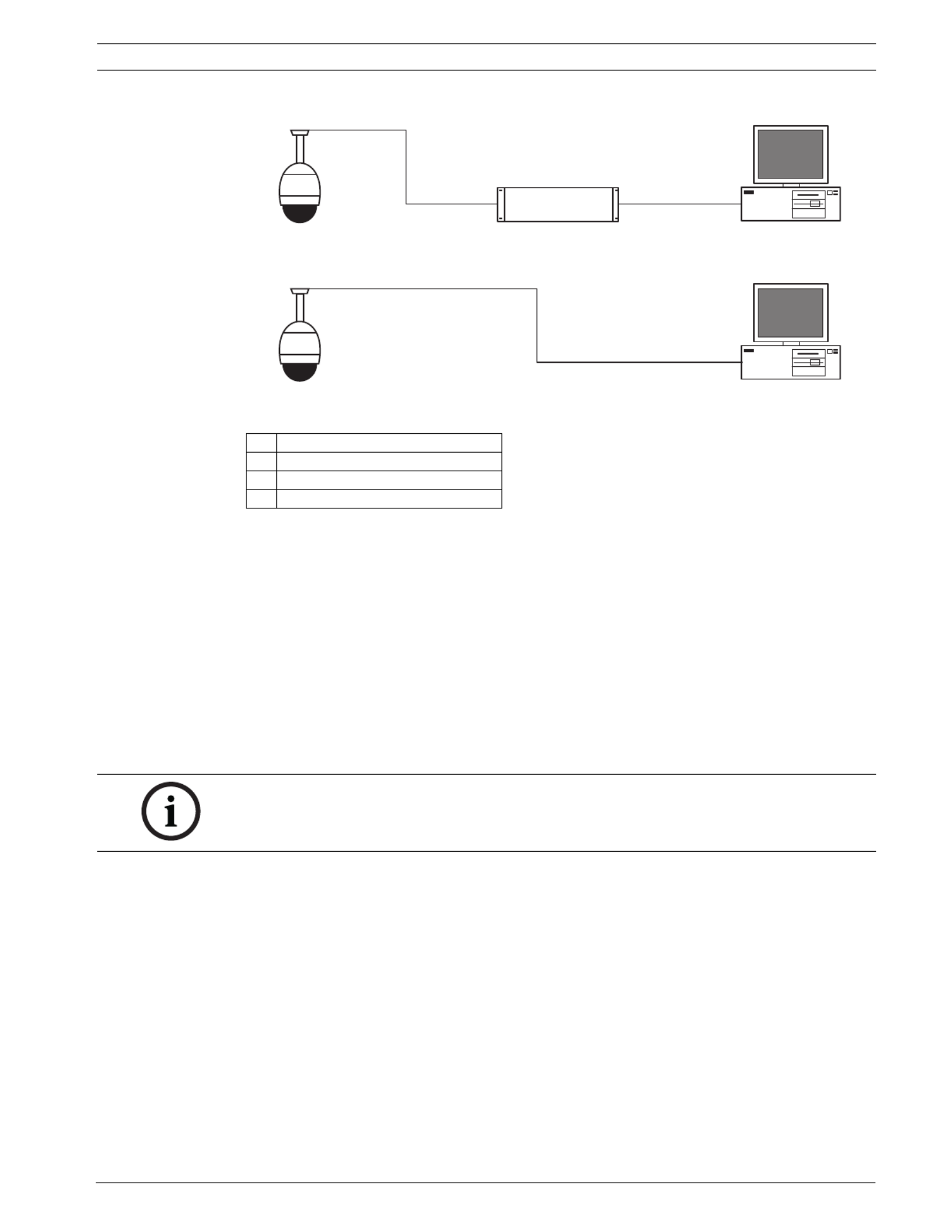
VG4 Modular Camera System Using the IP AutoDome | en 57
Bosch Security Systems, Inc. User’s Manual F.01U.133.268 | 6.0 | 2010.03
Figure 8.1 IP AutoDome System Configuration
8.4 Configuring the IP AutoDome Camera
To operate the camera in your network you must assign it a valid network IP address. The
default IP address is 192.168.0.1, but you may have to change this address if it conflicts with
another device on your network.
To properly configure the camera for your network, you need the following information:
– Unit IP address: An identifier for the camera on a TCP/IP network. For example,
140.10.2.110 is a valid syntax for an IP address.
– Subnet mask: A mask used to determine what subnet an IP address belongs to.
– Gateway IP address: A node on a network that serves as an entrance to another network.
– Port: An endpoint to a logical connection in TCP/IP and UDP networks. The port number
identifies the use of the port for use through a firewall connection.
The IP AutoDome defaults are as follows:
– IP Address: 192.168.0.1
– Subnet Mask: 255.255.255.0
– Gateway IP Address: 0.0.0.0
The following sections provide instructions about installing the software necessary to view
images over an IP connection, configuring the IP network settings and accessing the IP
AutoDome images from a Web browser.
1 AutoDome
2 IP Connection
3 Network Switch
4 Computer
1
2
34
1
2
2
4
NOTICE!
Ensure that the network parameters of your cameras are available before you begin
configuration.

58 en | Using the IP AutoDome VG4 Modular Camera System
F.01U.133.268 | 6.0 | 2010.03 User’s Manual Bosch Security Systems, Inc.
8.5 Installing the Required Software
To view live video, you must install Bosch MPEG ActiveX, DirectX, and Java Virtual Machine.
To view live video from an IP-enabled VG4 AutoDome in Microsoft Internet Explorer or to
change VG4 AutoDome configurations, you must install the following software in this order:
1. Sun Java
2. Microsoft .NET
3. Microsoft DirectX
4. MPEG-ActiveX
5. Bosch Configuration Manager
You can find the latest versions of the required software on the Bosch Security Systems, Inc.
Web site. To locate the software, follow these directions:
1. Launch a Web browser and navigate to one of the following URLs:
– For customers in the United States: http://www.boschsecurity.us
– For customers outside of the United States: http://www.boschsecurity.com, then
click your region and finally click the link for your country (if available).
2. Click the CCTV or Products link (depending on the country Web site) in the left pane of
the Web page.
3. Click the link under the Download LibrSoftware ary section in the left pane.
4. Click OK to agree to the Bosch Software License Agreement.
5. Click the CCTV link under the Software heading in the center frame.
6. Click the Cameras, PTZ link to access the software for Bosch PTZ cameras.
After you click re Download page for VG4 Cameras, PTZ the browser opens the Softwa
and VEZ AutoDomes.
7. Scroll down the page to the AutoDome TCP/IP Communications Module heading.
8. Right-click the appropriate language selection and choose Save Target As from the pop-
up menu for these software packages:
– Sun Java
– Microsoft .NET
– Microsoft DirectX
– MPEG-ActiveX
– ConfigManager
9. Save each software package to the computer that contains the Microsoft Internet
Explorer you will use to view the live video images from an IP-enabled VG4 AutoDome.
You should now have the following software packages stored on the computer:
–MPEG-ActiveXXX_enUS_E3366678923.zip (MPEG-ActiveX)
–DirectXXXX_enUS_E2352554507.zip (DirectX)
–dotnetfx_enUS_T5007298827.exe (.NET)
–jre-XXXX-windows-i586-p-s_xxXX_XXXXXXXXX.exe (Java)
–SetupConfigManagerXXXXXXXXX_enUS_F4155139595.exe (ConfigManager)
Note: The XXX denotes the software version number. This number changes as updates
are made to the software packages.

60 en | Using the IP AutoDome VG4 Modular Camera System
F.01U.133.268 | 6.0 | 2010.03 User’s Manual Bosch Security Systems, Inc.
Using the IP AutoDome Web Server
The IP AutoDome incorporates a network video server in the IP module.
To configure the camera using the IP AutoDome Web server, do the following:
1. Set the IP address on the PC to 192.168.0.10 to ensure that the PC and the IP
AutoDome are on the same Subnet.
2. Launch Microsoft Internet Explorer and navigate to the following URL: http://192.168.0.1
The Web browser opens the LivePage for the IP AutoDome; a security warning message is
displayed.
3. Check the Always Trust box, then click YES.
4. Click the Settings link, located at the top of the LivePage.
5. Click the Service Settings link, located in the left pane of the Settings window.
6. Click the Network link to open the Network Settings page.
Figure 8.2 Network Settings Page
7. Configure the settings on this page based on the addresses provided by your local
network administrator.
8. Click the Set button to save the settings.
9. Launch another instance of Microsoft Internet Explorer.
10. Type the original IP address followed by /reset (for example, http://192.168.0.1/reset) in
the address bar and click Go to restart the IP AutoDome. Once you restart the IP
AutoDome, use the new IP Address to access the LivePage.
11. Disconnect the IP AutoDome Ethernet cable from the dedicated network switch and
reconnect the Ethernet cable to the local area network (LAN).
NOTICE!
Click the Help on this page? link if you need more information.
Produkt Specifikationer
| Mærke: | Bosch |
| Kategori: | Overvågningskamera |
| Model: | AutoDome VG4161CCE |
Har du brug for hjælp?
Hvis du har brug for hjælp til Bosch AutoDome VG4161CCE stil et spørgsmål nedenfor, og andre brugere vil svare dig
Overvågningskamera Bosch Manualer

20 Februar 2025
3 Februar 2025
3 Februar 2025
8 December 2024
5 September 2024
5 September 2024
1 September 2024
28 August 2024
28 August 2024
28 August 2024
Overvågningskamera Manualer
- Overvågningskamera Denver
- Overvågningskamera Sony
- Overvågningskamera Canon
- Overvågningskamera Netis
- Overvågningskamera Samsung
- Overvågningskamera Panasonic
- Overvågningskamera Extech
- Overvågningskamera Moog
- Overvågningskamera TP-Link
- Overvågningskamera Philips
- Overvågningskamera Vitek
- Overvågningskamera Gigaset
- Overvågningskamera Pioneer
- Overvågningskamera Mitsubishi
- Overvågningskamera Braun
- Overvågningskamera Logitech
- Overvågningskamera Emos
- Overvågningskamera Google
- Overvågningskamera Technaxx
- Overvågningskamera HP
- Overvågningskamera Waeco
- Overvågningskamera Garmin
- Overvågningskamera Sanyo
- Overvågningskamera Grundig
- Overvågningskamera D-Link
- Overvågningskamera Arlo
- Overvågningskamera Motorola
- Overvågningskamera Asus
- Overvågningskamera Toshiba
- Overvågningskamera Pyle
- Overvågningskamera Kodak
- Overvågningskamera Furrion
- Overvågningskamera InFocus
- Overvågningskamera Nedis
- Overvågningskamera Friedland
- Overvågningskamera Abus
- Overvågningskamera Planet
- Overvågningskamera Adj
- Overvågningskamera Hama
- Overvågningskamera Creative
- Overvågningskamera Thomson
- Overvågningskamera Belkin
- Overvågningskamera Edimax
- Overvågningskamera Burg Wächter
- Overvågningskamera Clas Ohlson
- Overvågningskamera DataVideo
- Overvågningskamera Strong
- Overvågningskamera TRENDnet
- Overvågningskamera Smartwares
- Overvågningskamera Trevi
- Overvågningskamera Trust
- Overvågningskamera Laserliner
- Overvågningskamera Blaupunkt
- Overvågningskamera JVC
- Overvågningskamera Honeywell
- Overvågningskamera Uniden
- Overvågningskamera Buffalo
- Overvågningskamera Linksys
- Overvågningskamera Megasat
- Overvågningskamera Cisco
- Overvågningskamera EZVIZ
- Overvågningskamera König
- Overvågningskamera Elro
- Overvågningskamera Gembird
- Overvågningskamera Powerfix
- Overvågningskamera Alpine
- Overvågningskamera Netgear
- Overvågningskamera Maginon
- Overvågningskamera Yale
- Overvågningskamera Withings
- Overvågningskamera Nest
- Overvågningskamera Kerbl
- Overvågningskamera Vtech
- Overvågningskamera Exibel
- Overvågningskamera Genie
- Overvågningskamera Vaddio
- Overvågningskamera Bresser
- Overvågningskamera Western Digital
- Overvågningskamera Anker
- Overvågningskamera Digitus
- Overvågningskamera Zebra
- Overvågningskamera Jensen
- Overvågningskamera Alecto
- Overvågningskamera Flamingo
- Overvågningskamera Rollei
- Overvågningskamera Olympia
- Overvågningskamera Xiaomi
- Overvågningskamera Niceboy
- Overvågningskamera Aiptek
- Overvågningskamera Schneider
- Overvågningskamera B/R/K
- Overvågningskamera Marmitek
- Overvågningskamera Tesla
- Overvågningskamera Imou
- Overvågningskamera Ricoh
- Overvågningskamera Nexxt
- Overvågningskamera Aida
- Overvågningskamera APC
- Overvågningskamera Foscam
- Overvågningskamera Lorex
- Overvågningskamera Ikan
- Overvågningskamera Velleman
- Overvågningskamera LevelOne
- Overvågningskamera Marshall
- Overvågningskamera FLIR
- Overvågningskamera Perel
- Overvågningskamera Swann
- Overvågningskamera Vivotek
- Overvågningskamera Joblotron
- Overvågningskamera JUNG
- Overvågningskamera ORNO
- Overvågningskamera Binatone
- Overvågningskamera ZyXEL
- Overvågningskamera Fortinet
- Overvågningskamera Netatmo
- Overvågningskamera Tenda
- Overvågningskamera Eufy
- Overvågningskamera Ring
- Overvågningskamera M-e
- Overvågningskamera Overmax
- Overvågningskamera Somfy
- Overvågningskamera Y-cam
- Overvågningskamera Hikvision
- Overvågningskamera Monacor
- Overvågningskamera ION
- Overvågningskamera Raymarine
- Overvågningskamera Ubiquiti Networks
- Overvågningskamera AVerMedia
- Overvågningskamera EnGenius
- Overvågningskamera Reolink
- Overvågningskamera Grandstream
- Overvågningskamera Trebs
- Overvågningskamera EVE
- Overvågningskamera Renkforce
- Overvågningskamera Marshall Electronics
- Overvågningskamera Manhattan
- Overvågningskamera SPC
- Overvågningskamera Caliber
- Overvågningskamera Pentatech
- Overvågningskamera Switel
- Overvågningskamera AVtech
- Overvågningskamera LogiLink
- Overvågningskamera Orion
- Overvågningskamera Eminent
- Overvågningskamera Kramer
- Overvågningskamera QSC
- Overvågningskamera Hanwha
- Overvågningskamera Brilliant
- Overvågningskamera Lanberg
- Overvågningskamera Hive
- Overvågningskamera Siedle
- Overvågningskamera BirdDog
- Overvågningskamera Evolveo
- Overvågningskamera Genius
- Overvågningskamera KJB Security Products
- Overvågningskamera Valueline
- Overvågningskamera Provision-ISR
- Overvågningskamera Quantum
- Overvågningskamera Axis
- Overvågningskamera ACTi
- Overvågningskamera CRUX
- Overvågningskamera Avanti
- Overvågningskamera Vimar
- Overvågningskamera Aluratek
- Overvågningskamera Dahua Technology
- Overvågningskamera Chacon
- Overvågningskamera SereneLife
- Overvågningskamera ZKTeco
- Overvågningskamera AG Neovo
- Overvågningskamera Stabo
- Overvågningskamera EtiamPro
- Overvågningskamera First Alert
- Overvågningskamera Speco Technologies
- Overvågningskamera Boss
- Overvågningskamera Broan
- Overvågningskamera Conceptronic
- Overvågningskamera Avidsen
- Overvågningskamera Crestron
- Overvågningskamera Lindy
- Overvågningskamera Kogan
- Overvågningskamera AVMATRIX
- Overvågningskamera Delta Dore
- Overvågningskamera Promise Technology
- Overvågningskamera Sitecom
- Overvågningskamera DiO
- Overvågningskamera Minox
- Overvågningskamera Intellinet
- Overvågningskamera V-TAC
- Overvågningskamera Qian
- Overvågningskamera August
- Overvågningskamera IDIS
- Overvågningskamera Geovision
- Overvågningskamera Schwaiger
- Overvågningskamera Steren
- Overvågningskamera Elmo
- Overvågningskamera AViPAS
- Overvågningskamera UniView
- Overvågningskamera Equip
- Overvågningskamera Alfatron
- Overvågningskamera REVO
- Overvågningskamera Aqara
- Overvågningskamera Ernitec
- Overvågningskamera Setti+
- Overvågningskamera BZBGear
- Overvågningskamera PTZ Optics
- Overvågningskamera AVer
- Overvågningskamera Ferguson
- Overvågningskamera Moxa
- Overvågningskamera Inovonics
- Overvågningskamera Bea-fon
- Overvågningskamera Profile
- Overvågningskamera WyreStorm
- Overvågningskamera Allnet
- Overvågningskamera Aldi
- Overvågningskamera Airlive
- Overvågningskamera Aritech
- Overvågningskamera ACME
- Overvågningskamera KlikaanKlikuit
- Overvågningskamera Marquant
- Overvågningskamera Ednet
- Overvågningskamera Lumens
- Overvågningskamera Hombli
- Overvågningskamera Naxa
- Overvågningskamera Miniland
- Overvågningskamera Xavax
- Overvågningskamera Gira
- Overvågningskamera Interlogix
- Overvågningskamera DSC
- Overvågningskamera Boyo
- Overvågningskamera Iget
- Overvågningskamera EverFocus
- Overvågningskamera Adesso
- Overvågningskamera Satel
- Overvågningskamera Notifier
- Overvågningskamera Monoprice
- Overvågningskamera Beafon
- Overvågningskamera Chuango
- Overvågningskamera MicroView
- Overvågningskamera ETiger
- Overvågningskamera Videcon
- Overvågningskamera INSTAR
- Overvågningskamera Advantech
- Overvågningskamera Digital Watchdog
- Overvågningskamera Moen
- Overvågningskamera Ganz
- Overvågningskamera MEE Audio
- Overvågningskamera Mobotix
- Overvågningskamera Kwikset
- Overvågningskamera Ikegami
- Overvågningskamera Leviton
- Overvågningskamera Pelco
- Overvågningskamera Approx
- Overvågningskamera ClearOne
- Overvågningskamera Ebode
- Overvågningskamera Oplink
- Overvågningskamera Dorr
- Overvågningskamera Sonic Alert
- Overvågningskamera Linear PRO Access
- Overvågningskamera Summer Infant
- Overvågningskamera SMC
- Overvågningskamera Topica
- Overvågningskamera Iiquu
- Overvågningskamera Verint
- Overvågningskamera Brinno
- Overvågningskamera Rostra
- Overvågningskamera Caddx
- Overvågningskamera Spyclops
- Overvågningskamera EKO
- Overvågningskamera Kguard
- Overvågningskamera Woonveilig
- Overvågningskamera Accsoon
- Overvågningskamera Mobi
- Overvågningskamera Surveon
- Overvågningskamera Hollyland
- Overvågningskamera Epcom
- Overvågningskamera Indexa
- Overvågningskamera Lutec
- Overvågningskamera Whistler
- Overvågningskamera ClearView
- Overvågningskamera VideoComm
- Overvågningskamera IMILAB
- Overvågningskamera 3xLOGIC
- Overvågningskamera Inkovideo
- Overvågningskamera Weldex
- Overvågningskamera SecurityMan
- Overvågningskamera Mach Power
- Overvågningskamera Canyon
- Overvågningskamera CNB Technology
- Overvågningskamera Tapo
- Overvågningskamera Aigis
- Overvågningskamera Exacq
- Overvågningskamera Brickcom
- Overvågningskamera Laxihub
- Overvågningskamera Securetech
- Overvågningskamera EFB Elektronik
- Overvågningskamera NetMedia
- Overvågningskamera Videotec
- Overvågningskamera Illustra
- Overvågningskamera Atlona
- Overvågningskamera Nivian
- Overvågningskamera Arenti
- Overvågningskamera E-bench
- Overvågningskamera Blow
- Overvågningskamera Syscom
- Overvågningskamera Tecno
- Overvågningskamera Night Owl
- Overvågningskamera Guardzilla
- Overvågningskamera Astak
- Overvågningskamera Blink
- Overvågningskamera Milestone Systems
- Overvågningskamera Zavio
- Overvågningskamera Campark
- Overvågningskamera IPX
- Overvågningskamera Dedicated Micros
- Overvågningskamera Hamlet
- Overvågningskamera Annke
- Overvågningskamera Qoltec
- Overvågningskamera Digimerge
- Overvågningskamera Feelworld
- Overvågningskamera Wisenet
- Overvågningskamera Infortrend
- Overvågningskamera Epiphan
- Overvågningskamera HiLook
- Overvågningskamera Compro
- Overvågningskamera Vimtag
- Overvågningskamera Sonoff
- Overvågningskamera Gewiss
- Overvågningskamera Alula
- Overvågningskamera Insteon
- Overvågningskamera Costar
- Overvågningskamera ALC
- Overvågningskamera Security Labs
- Overvågningskamera Comtrend
- Overvågningskamera Seneca
- Overvågningskamera Avigilon
- Overvågningskamera American Dynamics
- Overvågningskamera Vosker
- Overvågningskamera Sentry360
- Overvågningskamera Owltron
- Overvågningskamera Petcube
- Overvågningskamera Enabot
- Overvågningskamera Luis Energy
- Overvågningskamera Sir Gawain
- Overvågningskamera VisorTech
- Overvågningskamera Atlantis Land
- Overvågningskamera B & S Technology
- Overvågningskamera I3International
- Overvågningskamera Ecobee
- Overvågningskamera Turing
- Overvågningskamera Wasserstein
- Overvågningskamera Qolsys
- Overvågningskamera Control4
- Overvågningskamera Milesight
- Overvågningskamera GVI Security
- Overvågningskamera Conbrov
- Overvågningskamera HuddleCamHD
- Overvågningskamera Defender
- Overvågningskamera IOIO
- Overvågningskamera BIRDFY
- Overvågningskamera I-PRO
- Overvågningskamera DVDO
- Overvågningskamera TCP
- Overvågningskamera Bolin Technology
- Overvågningskamera Nextech
- Overvågningskamera Tuya
- Overvågningskamera Bolide
- Overvågningskamera Telycam
- Overvågningskamera Arecont Vision
- Overvågningskamera Schlage
Nyeste Overvågningskamera Manualer

7 April 2025
7 April 2025
6 April 2025
29 Marts 2025
28 Marts 2025
20 Marts 2025
20 Marts 2025
20 Marts 2025
13 Marts 2025
8 Marts 2025