Candy fp 319 x Manual
Læs nedenfor 📖 manual på dansk for Candy fp 319 x (366 sider) i kategorien Ovn. Denne guide var nyttig for 38 personer og blev bedømt med 4.5 stjerner i gennemsnit af 2 brugere
Side 1/366
613-001490 Rev A
AT-GS950/24
Gigabit Ethernet Smart Switch
AT-GS950/24 Web Users Guide
AT-S109 Version 1.1.0 [1.00.043]
Copyright © 2011 Allied Telesis, Inc.
All rights reserved. No part of this publication may be reproduced without prior written permission from Allied Telesis,
Inc.
Allied Telesis and the Allied Telesis logo are trademarks of Allied Telesis, Incorporated. All other product names,
company names, logos or other designations mentioned herein are trademarks or registered trademarks of their respective
owners.
Allied Telesis, Inc. reserves the right to make changes in specifications and other information contained in this document
without prior written notice. The information provided herein is subject to change without notice. In no event shall Allied
Telesis, Inc. be liable for any incidental, special, indirect, or consequential damages whatsoever, including but not limited
to lost profits, arising out of or related to this manual or the information contained herein, even if Allied Telesis, Inc. has
been advised of, known, or should have known, the possibility of such damages.

3
Contents
List of Figures .................................................................................................................................................. 9
List of Tables ................................................................................................................................................. 13
Preface ............................................................................................................................................................ 15
Where to Find Web-based Product Information......................................................................................... 16
Contacting Allied Telesis............................................................................................................................ 17
Online Support..................................................................................................................................... 17
Email and Telephone Support ............................................................................................................. 17
Warranty .............................................................................................................................................. 17
Returning Products.............................................................................................................................. 17
Sales or Corporate Information ........................................................................................................... 17
Management Software Updates .......................................................................................................... 17
Chapter 1: Starting a Web Browser Session ................................................................................................ 19
Establishing a Remote Connection to the Web Browser Interface ............................................................ 20
Web Browser Tools.................................................................................................................................... 23
Quitting a Web Browser Management Session ......................................................................................... 24
Chapter 2: Basic Switch Configuration ......................................................................................................... 25
Configuration of IP Address, Subnet Mask and Gateway Address............................................................ 26
IP Access List Configuration ...................................................................................................................... 28
Create an IP Access List ..................................................................................................................... 28
Delete an IP Address List Entry........................................................................................................... 30
System Time .............................................................................................................................................. 31
Manually Setting System Time ............................................................................................................ 31
Setting SNTP....................................................................................................................................... 32
Setting Daylight Savings Parameters .................................................................................................. 33
DHCP and ATI Web Discovery Tool .......................................................................................................... 34
DHCP Client Configuration ........................................................................................................................ 35
DHCP Auto Configuration .......................................................................................................................... 37
System Management Information .............................................................................................................. 38
User Name and Password Configuration................................................................................................... 40
Add New User Name and Password ................................................................................................... 40
Modify User Name and Password ....................................................................................................... 41
Delete User Name and Password ....................................................................................................... 42
User Interface Configuration ...................................................................................................................... 43
SNMP Interface ................................................................................................................................... 43
User Interface Timeout ........................................................................................................................ 44
System Information Display ....................................................................................................................... 45
Switch Reboot ............................................................................................................................................ 47
Password Protection of Factory Reset ................................................................................................ 47
Switch Reboot ..................................................................................................................................... 48
Configure Factory Default Values........................................................................................................ 49
Disabling Factory Default Reset Feature............................................................................................. 51
Enabling Factory Default Reset........................................................................................................... 52
Pinging a Remote System.......................................................................................................................... 54
Contents
4
SSL Settings............................................................................................................................................... 56
Configuring SSL ...................................................................................................................................56
System Log Configuration ..........................................................................................................................58
Chapter 3: Port Configuration ........................................................................................................................ 61
Overview..................................................................................................................................................... 62
Display and Configure Ports.......................................................................................................................63
Chapter 4: Port Mirroring ............................................................................................................................... 69
Overview..................................................................................................................................................... 70
Port Mirroring Configuration ....................................................................................................................... 71
Disable Port Mirroring................................................................................................................................. 73
Chapter 5: Virtual LANs .................................................................................................................................75
VLAN Overview ..........................................................................................................................................76
Port-based VLAN Overview .................................................................................................................77
Tagged VLAN Overview.......................................................................................................................78
Assign Ports to a VLAN Mode ....................................................................................................................81
Tagged VLAN Configuration....................................................................................................................... 83
Create a Tagged VLAN........................................................................................................................83
Modify a Tagged VLAN........................................................................................................................ 84
Delete a Tagged VLAN ........................................................................................................................87
Tagged VLAN Port Settings ....................................................................................................................... 89
Port-Based VLAN Configuration.................................................................................................................91
Create a Port-Based VLAN .................................................................................................................. 91
Modify a Port-Based VLAN ..................................................................................................................92
Delete a Port-Based VLAN ..................................................................................................................92
Chapter 6: GVRP .......................................................................................................................................... 95
Overview and Guidelines............................................................................................................................96
General Configuration ................................................................................................................................97
Port Settings ............................................................................................................................................... 98
Time Settings............................................................................................................................................100
Chapter 7: Voice VLAN ...............................................................................................................................103
Overview...................................................................................................................................................104
CoS with Voice VLAN ........................................................................................................................104
Organization Unique Identifier (OUI)..................................................................................................104
Dynamic Auto-Detection vs Static Ports ............................................................................................105
General Guidelines...................................................................................................................................107
Configuration ............................................................................................................................................ 108
OUI Setting ...............................................................................................................................................111
Create OUI Setting.............................................................................................................................111
Modify OUI Setting .............................................................................................................................112
Delete OUI Setting .............................................................................................................................112
Chapter 8: STP and RSTP .......................................................................................................................... 113
Overview...................................................................................................................................................114
Bridge Priority and the Root Bridge....................................................................................................115
Forwarding Delay and Topology Changes.........................................................................................117
Mixed STP and RSTP Networks ........................................................................................................119
Spanning Tree and VLANs ................................................................................................................120
Basic STP and RSTP Configuration.........................................................................................................123
Configure RSTP Port Settings..................................................................................................................126
Configure the Basic RSTP Port Settings............................................................................................126
Configure the Advanced RSTP Port Settings ....................................................................................128
Spanning Tree Topology ..........................................................................................................................131
AT-GS950/24 Web Interface User Guide
5
Chapter 9: Multiple Spanning Tree Protocol ............................................................................................... 133
Multiple Spanning Tree Configuration...................................................................................................... 134
Head2 ................................................................................................................................................ 134
VLAN Mapping ......................................................................................................................................... 137
Open MSTP VLAN Mapping Page .................................................................................................... 137
Create VLAN Mapping to MST Instance ........................................................................................... 137
Modify MST Instance......................................................................................................................... 138
Delete MST Instance ......................................................................................................................... 138
Port Configuration .................................................................................................................................... 139
Port Settings............................................................................................................................................. 142
Topology Information ............................................................................................................................... 144
Chapter 10: Static Port Trunking ................................................................................................................ 147
Overview .................................................................................................................................................. 148
Create a Port Trunk.................................................................................................................................. 151
Modify a Port Trunk.................................................................................................................................. 153
Disable a Port Trunk ................................................................................................................................ 155
Chapter 11: LACP Port Trunks ................................................................................................................... 157
Overview .................................................................................................................................................. 158
System Priority ......................................................................................................................................... 159
Port Priority Value .................................................................................................................................... 159
General Guidelines .................................................................................................................................. 161
Group Status ............................................................................................................................................ 163
Configuration Example ...................................................................................................................... 164
Port Priority Configuration ........................................................................................................................ 166
Chapter 12: Quality of Service (CoS) ......................................................................................................... 167
Overview .................................................................................................................................................. 168
Packet Priority ................................................................................................................................... 168
Egress Queue vs Packet Priority Mapping ........................................................................................ 169
Prioritizing Untagged Packets ........................................................................................................... 170
Scheduling......................................................................................................................................... 170
Mapping CoS Priorities to Egress Queues............................................................................................... 173
Associate Ports to CoS Priorities ............................................................................................................. 175
Associate DSCP Classes to Egress Queues ........................................................................................... 176
Queue Scheduling Algorithm ................................................................................................................... 177
Chapter 13: Access Control Configuration ................................................................................................. 179
Classifier .................................................................................................................................................. 180
Create Classifier ................................................................................................................................ 180
Modify Classifier ................................................................................................................................ 182
Delete Classifier ................................................................................................................................ 183
Profile Action ............................................................................................................................................ 185
Create Profile Action.......................................................................................................................... 185
Modify Profile Action.......................................................................................................................... 186
Delete Profile Action .......................................................................................................................... 187
In-Profile Action........................................................................................................................................ 189
Create In-Profile Action ..................................................................................................................... 189
Modify In-Profile Action...................................................................................................................... 191
Delete In-Profile Action...................................................................................................................... 192
Out-Profile Action ..................................................................................................................................... 193
Create Out-Profile Action................................................................................................................... 193
Modify Out-Profile Action................................................................................................................... 195
Delete Out-Profile Action ................................................................................................................... 196
Contents
6
Port List ....................................................................................................................................................197
Create Port List .................................................................................................................................. 197
Modify Port List ..................................................................................................................................198
Delete Port List...................................................................................................................................199
Policy ........................................................................................................................................................200
Create Policy......................................................................................................................................200
Modify Policy ......................................................................................................................................202
Delete Policy ......................................................................................................................................203
Policy Sequence.......................................................................................................................................205
Chapter 14: Storm Control ..........................................................................................................................207
Overview...................................................................................................................................................208
Ingress Rate Limiting .........................................................................................................................209
Egress Rate Limiting ..........................................................................................................................209
Configuration ............................................................................................................................................ 210
Ingress Rate Limiting................................................................................................................................ 212
Egress Rate Limiting ................................................................................................................................214
Chapter 15: MAC Address Table ................................................................................................................215
Overview...................................................................................................................................................216
Static Unicast MAC Address Configuration ..............................................................................................218
Modify Static Unicast Address..................................................................................................................220
Delete Static Unicast Address ..................................................................................................................221
Static Multicast Address Configuration.....................................................................................................222
Modify Static Multicast Address................................................................................................................224
Delete Static Multicast Address................................................................................................................225
Chapter 16: DHCP Snooping ......................................................................................................................227
Overview...................................................................................................................................................228
Trusted Ports...................................................................................................................................... 228
Untrusted Ports .................................................................................................................................. 228
Unauthorized DHCP Servers .............................................................................................................228
DHCP with Option 82 .........................................................................................................................229
General Guidelines...................................................................................................................................230
General Configuration ..............................................................................................................................231
VLAN Setting ............................................................................................................................................233
Create VLAN Setting.......................................................................................................................... 233
Modify VLAN Setting ..........................................................................................................................234
Delete VLAN Setting ..........................................................................................................................234
Trusted and Untrusted Port Configuration................................................................................................235
Binding Database ..................................................................................................................................... 236
Static IP Addresses............................................................................................................................236
Viewing...............................................................................................................................................237
Chapter 17: IGMP Snooping .......................................................................................................................239
Overview...................................................................................................................................................240
IGMP Snooping Configuration..................................................................................................................242
Chapter 18: Security ...................................................................................................................................245
Port Access Control.................................................................................................................................. 246
Overview ............................................................................................................................................246
Port Access Control Configuration .....................................................................................................247
RADIUS Client..........................................................................................................................................251
Overview ............................................................................................................................................251
General Guidelines ............................................................................................................................251
Radius Client Configuration ...............................................................................................................252
AT-GS950/24 Web Interface User Guide
7
Dial-in User - Local Authentication........................................................................................................... 254
Overview............................................................................................................................................ 254
Dial-in User Configuration ................................................................................................................. 254
Destination MAC Filter ............................................................................................................................. 257
Overview............................................................................................................................................ 257
Destination MAC Filter Configuration ................................................................................................ 257
Delete Destination MAC Filter ........................................................................................................... 258
Chapter 19: LLDP ....................................................................................................................................... 259
Overview .................................................................................................................................................. 260
Global Configuration ................................................................................................................................ 261
Enable/Disable LLDP ........................................................................................................................ 261
System Information............................................................................................................................ 262
Port States......................................................................................................................................... 263
Neighbors Information.............................................................................................................................. 264
Chapter 20: Simple Network Management Protocol SNMPv1 and v2c ...................................................... 265
SNMPv1 and SNMPv2c Overview ........................................................................................................... 266
Trap Receiver Attributes .......................................................................................................................... 267
Activate SNMP Interface .......................................................................................................................... 268
SNMPv1/v2 User and Group Names ....................................................................................................... 269
Create SNMP v1/v2 User and Group Names.................................................................................... 269
Modify SNMPv1/v2 User and Group Names ..................................................................................... 270
Delete SNMPv1/v2 User and Group Names ..................................................................................... 270
SNMPv1/v2 Community Strings............................................................................................................... 271
Create SNMPv1/v2 Community Strings ............................................................................................ 271
Modify SNMPv1/v2 Community Strings............................................................................................. 272
Delete SNMPv1/v2 Community Strings............................................................................................. 272
SNMP Traps............................................................................................................................................. 273
Create Trap Host Table Entry............................................................................................................ 273
Modify Trap Host Table Entry............................................................................................................ 274
Delete Trap Host Table Entry ............................................................................................................ 274
Chapter 21: Simple Network Management Protocol SNMPv3 ................................................................... 275
SNMPv3 Overview ................................................................................................................................... 276
SNMPv3 Authentication Protocols..................................................................................................... 276
SNMPv3 Privacy Protocol ................................................................................................................. 277
SNMPv3 MIB Views .......................................................................................................................... 277
SNMPv3 Configuration Process ........................................................................................................ 278
SNMPv3 User and Group Names ............................................................................................................ 280
Create SNMPv3 User and Group Names.......................................................................................... 280
Modify SNMPv3 User and Group Names .......................................................................................... 281
Delete SNMPv3 User and Group Names .......................................................................................... 281
SNMPv3 View Names.............................................................................................................................. 282
Create SNMPv3 View Names ........................................................................................................... 282
Modify SNMPv3 View Names............................................................................................................ 283
Delete SNMPv3 View Names............................................................................................................ 283
View Table ............................................................................................................................................... 285
Create SNMPv3 View Table Entries.................................................................................................. 285
Modify SNMPv3 View Table Entries.................................................................................................. 286
Delete SNMPv3 View Table Entries .................................................................................................. 286
SNMPv3 Traps......................................................................................................................................... 287
Contents
8
Chapter 22: RMON .....................................................................................................................................289
Overview...................................................................................................................................................290
Enable and Disable RMON ...................................................................................................................... 291
Port Statistics............................................................................................................................................292
Histories....................................................................................................................................................293
Events.......................................................................................................................................................295
Alarms ......................................................................................................................................................297
Chapter 23: Network Statistics ....................................................................................................................301
Overview...................................................................................................................................................302
Traffic Comparison Statistics.................................................................................................................... 303
Error Group Statistics ...............................................................................................................................306
Historical Status Charts ............................................................................................................................308
Chapter 24: Management Software Updates ..............................................................................................311
Overview...................................................................................................................................................312
Upgrade Firmware Image via HTTP.........................................................................................................313
Upgrade Firmware Image via TFTP .........................................................................................................315
Download or Upload a Configuration File via HTTP.................................................................................317
Configuration File Upload...................................................................................................................318
Configuration File Download ..............................................................................................................318
Download or Upload a Configuration File via TFTP .................................................................................320
Configuration File Upload...................................................................................................................320
Configuration File Download ..............................................................................................................321
Chapter 25: Loopback Protection ................................................................................................................323
Configuration ............................................................................................................................................ 324
Status .......................................................................................................................................................326
Chapter 26: Cable Diagnostics ...................................................................................................................327
Appendix A: MSTP Overview .......................................................................................................................329
Overview...................................................................................................................................................330
Multiple Spanning Tree Instance (MSTI) ..................................................................................................332
Resolving VLAN Fragmentation.........................................................................................................332
Multiple VLANS Assigned to an MSTI................................................................................................333
General Guidelines...................................................................................................................................335
VLAN and MSTI Associations .................................................................................................................. 336
Ports in Multiple MSTIs.............................................................................................................................337
Multiple Spanning Tree Regions ..............................................................................................................338
MST Region Guidelines .....................................................................................................................340
Common and Internal Spanning Tree (CIST) ....................................................................................342
MSTP with STP and RSTP ................................................................................................................342
Associating VLANs to MSTIs....................................................................................................................343
VLANs Across Different Regions..............................................................................................................345
Summary of Guidelines ............................................................................................................................347
Appendix A: AT-GS950/24 Default Parameters ...........................................................................................349

9
Figure 1. Entering a Switch’s IP Address in the URL Field................................................................................................ 20
Figure 2. Management Login Dialog Box .......................................................................................................................... 20
Figure 3. AT-GS950/24 Switch Information Page.............................................................................................................. 21
Figure 4. AT-GS950/24 Front Panel Page......................................................................................................................... 22
Figure 5. IP Setup Page .................................................................................................................................................... 26
Figure 6. IP Access List Page ........................................................................................................................................... 28
Figure 7. System Time Page ............................................................................................................................................. 31
Figure 8. DHCP Auto Configuration Settings Page ........................................................................................................... 37
Figure 9. AT-GS950/24 Management Page ...................................................................................................................... 38
Figure 10. Administration Page ......................................................................................................................................... 40
Figure 11. Modify Administration Page.............................................................................................................................. 41
Figure 12. User Interface Page ......................................................................................................................................... 43
Figure 13. AT-GS950/24 Switch Information Page............................................................................................................ 45
Figure 14. Factory Default Reset/Reboot Page................................................................................................................. 49
Figure 15. Factory Default Reset/Reboot Page with Password Entry ............................................................................... 51
Figure 16. Factory Default Reset Disabled Page .............................................................................................................. 52
Figure 17. Factory Default Reset/Reboot Page with Password Entry ............................................................................... 53
Figure 18. Ping Test Configuration Page........................................................................................................................... 54
Figure 19. Ping Test Results Page.................................................................................................................................... 55
Figure 20. SSL Settings Page ........................................................................................................................................... 56
Figure 21. System Log Configuration Page....................................................................................................................... 58
Figure 22. AT-GS950/24 Physical Interface Page............................................................................................................. 63
Figure 23. AT-GS950/24 Mirroring Page........................................................................................................................... 71
Figure 24. AT-GS950/24 VLAN Mode Page...................................................................................................................... 81
Figure 25. AT-GS950/24 Tagged VLAN Page................................................................................................................... 83
Figure 26. Example of AT-GS950/24 Tagged VLAN Page................................................................................................ 85
Figure 27. AT-GS950/24 Modify VLAN Page .................................................................................................................... 85
Figure 28. AT-GS950/24 VLAN Port Setting Page ............................................................................................................ 89
Figure 29. Port-Based VLAN Page.................................................................................................................................... 91
Figure 30. AT-GS950/24 Modify Port-based VLAN ........................................................................................................... 92
Figure 31. GVRP Global Configuration Page .................................................................................................................... 97
Figure 32. AT-GS950/24 Port Settings Page..................................................................................................................... 98
Figure 33. AT-GS950/24 GVRP Time Setting Page........................................................................................................ 100
Figure 34. AT-GS950/24 Voice VLAN Setting Page........................................................................................................ 108
Figure 35. Voice VLAN OUI Setting Page. ...................................................................................................................... 111
Figure 36. Point-to-Point Ports ........................................................................................................................................ 119
Figure 37. Edge Port ....................................................................................................................................................... 119
Figure 38. STP and VLAN Fragmentation with Untagged Ports...................................................................................... 121
Figure 39. STP and VLAN Compatibility with Tagged Ports............................................................................................ 122
Figure 40. Rapid Spanning Tree Configuration Page...................................................................................................... 123
Figure 41. AT-GS950/24 RSTP Basic Port Configuration Page...................................................................................... 126
Figure 42. AT-GS950/24 RSTP Advanced Port Configuration Page............................................................................... 129
Figure 43. AT-GS950/24 Designated Topology Information Page .................................................................................. 131
Figure 44. Multiple Spanning Tree Configuration Page................................................................................................... 134
Figure 45. MSTP VLAN Mapping Page ........................................................................................................................... 137
Figure 46. AT-GS950/24 MSTP Port Configuration Page ............................................................................................... 139
Figure 47. MSTP Port Settings Page............................................................................................................................... 142
Figure 48. AT-GS950/24 Topology Information Page ..................................................................................................... 144
Figure 49. Static Port Trunk Example.............................................................................................................................. 148
Figure 50. Trunking Page ................................................................................................................................................ 151
List of Figures
Figures
10
Figure 51. LACP Group Status Page............................................................................................................................... 163
Figure 52. LACP Group Status Page with No Cables Connected ................................................................................... 164
Figure 53. LACP Group Status Page with Three Cables Connected .............................................................................. 165
Figure 54. AT-GS950/24 Port Priority Page..................................................................................................................... 166
Figure 55. CoS Page ....................................................................................................................................................... 173
Figure 56. AT-GS950/24 Port Priority Page..................................................................................................................... 175
Figure 57. DSCP Class Mapping Page............................................................................................................................ 176
Figure 58. Scheduling Algorithm Page ............................................................................................................................ 177
Figure 59. Create Classifier Page.................................................................................................................................... 180
Figure 60. Example of a Classifier Entry.......................................................................................................................... 182
Figure 61. Modify Classifier Page.................................................................................................................................... 183
Figure 62. Create Profile Action Page ............................................................................................................................. 185
Figure 63. Example of Profile Action Entry ...................................................................................................................... 186
Figure 64. Modify Profile Action Page.............................................................................................................................. 187
Figure 65. Create In-Profile Action Page ......................................................................................................................... 189
Figure 66. Example of In-Profile Action Entry .................................................................................................................. 190
Figure 67. Modify In-Profile Action Page ......................................................................................................................... 191
Figure 68. Create Out-Profile Action Page ...................................................................................................................... 193
Figure 69. Example of Out-Profile Action Entry ............................................................................................................... 194
Figure 70. Modify Out-Profile Action Page....................................................................................................................... 195
Figure 71. Create Port List Page ..................................................................................................................................... 197
Figure 72. Example of Port List Entry .............................................................................................................................. 198
Figure 73. Modify Port List Page...................................................................................................................................... 199
Figure 74. Create Policy Page......................................................................................................................................... 200
Figure 75. Example of Policy Entry.................................................................................................................................. 202
Figure 76. Modify Policy Page ......................................................................................................................................... 203
Figure 77. Policy Sequence Page.................................................................................................................................... 205
Figure 78. AT-GS950/24 Storm Control Page ................................................................................................................. 210
Figure 79. AT-GS950/24 Ingress Rate Limiting Page...................................................................................................... 212
Figure 80. AT-GS950/24 Egress Rate Limiting Page ...................................................................................................... 214
Figure 81. AT-GS950/24 Static Unicast Address Table Page ......................................................................................... 218
Figure 82. AT-GS950/24 Static Multicast Address Table Page ....................................................................................... 222
Figure 83. General Settings Page.................................................................................................................................... 231
Figure 84. DHCP Snooping VLAN Settings Page............................................................................................................ 233
Figure 85. AT-GS950/24 Trusted Interfaces Page .......................................................................................................... 235
Figure 86. AT-GS950/24 Binding Database Page........................................................................................................... 236
Figure 87. IGMP Snooping Page..................................................................................................................................... 242
Figure 88. IGMP Snooping Page with MAC Address ...................................................................................................... 243
Figure 89. Port Access Control Configuration Page ........................................................................................................ 247
Figure 90. RADIUS Page................................................................................................................................................. 252
Figure 91. Dial-In User Page ........................................................................................................................................... 255
Figure 92. Destination MAC Filter Page .......................................................................................................................... 258
Figure 93. AT-GS950/24 LLDP Global Settings Page ..................................................................................................... 261
Figure 94. LLDP Neighbors Information Page................................................................................................................. 264
Figure 95. User/Group Page............................................................................................................................................ 269
Figure 96. Community Table Page .................................................................................................................................. 271
Figure 97. Trap Management Page................................................................................................................................. 273
Figure 98. MIB Tree......................................................................................................................................................... 278
Figure 99. SNMP V3 Table Relationships ....................................................................................................................... 279
Figure 100. SNMP Group Access Table.......................................................................................................................... 282
Figure 101. SNMP View Table......................................................................................................................................... 285
Figure 102. RMON Basic Settings Page.......................................................................................................................... 291
Figure 103. Ethernet Statistics Configuration Page ......................................................................................................... 292
Figure 104. History Control Configuration Page .............................................................................................................. 293
Figure 105. RMON Event Configuration Page................................................................................................................. 295
Figure 106. RMON Alarm Configuration Page................................................................................................................. 298
Figure 107. Traffic Comparison Page.............................................................................................................................. 303
Figure 108. Error Group Chart Page................................................................................................................................ 306
Figure 109. Historical Status Chart Page......................................................................................................................... 308
Figure 110. Firmware Upgrade via HTTP Page............................................................................................................... 314
AT-GS950/24 Web Interface User Guide
11
Figure 111. Firmware Upgrade via TFTP Page............................................................................................................... 316
Figure 112. Configuration Upload/Download via HTTP Page ......................................................................................... 317
Figure 113. File Download with HTTP............................................................................................................................. 318
Figure 114. Result Page.................................................................................................................................................. 319
Figure 115. Configuration Upload/Download via TFTP Page.......................................................................................... 320
Figure 116. AT-GS950/24 Loopback Detection Page ..................................................................................................... 324
Figure 117. Cable Diagnostics Page ............................................................................................................................... 327
Figure 118. VLAN Fragmentation with STP or RSTP...................................................................................................... 332
Figure 119. MSTP Example of Two Spanning Tree Instances ....................................................................................... 333
Figure 120. Multiple VLANs in a MSTI............................................................................................................................. 334
Figure 121. Multiple Spanning Tree Region .................................................................................................................... 339
Figure 122. CIST and VLAN Guideline - Example 1........................................................................................................ 343
Figure 123. CIST and VLAN Guideline - Example 2........................................................................................................ 344
Figure 124. Spanning Regions - Example 1 .................................................................................................................... 345
Figure 125. Spanning Regions without Blocking ............................................................................................................. 346
Figures
12

13
List of Tables
Table 1. Bridge Priority Value Increments .................................................................................... 115
Table 2. Valid Port Priority Values ................................................................................................ 117
Table 3. Default Mappings Priority Levels to Priority Queues ...................................................... 169
Table 4. Customized Mappings Priority Levels to Priority Queues ............................................... 169
Table 5. Example of Weighted Round Robin Priority .................................................................... 172
Table 6. Traffic Comparison Options ............................................................................................ 304
Table 7. Historical Status Options ................................................................................................. 309
Table 8. Regional Bridge Priority Value Increments ..................................................................... 340
Table 9. AT-S109 Version 1.1.0 Management Software Default Settings ................................... 349
List of Tables
14

15
Preface
This guide contains instructions on how to use the AT-S109 Version 1.1.0
Management software to manage and monitor the AT-GS950/24 Gigabit
Ethernet Smart Switch.
The AT-S109 Version 1.1.0 Management software has a web browser
interface that you can access from any management workstation on your
network that has a web browser application.
This preface contains the following sections:
“Where to Find Web-based Product Information” on page 16
“Contacting Allied Telesis” on page 17

Preface
16
Where to Find Web-based Product Information
The product guides are available for all Allied Telesis products in portable
document format (PDF) on our web site. Management software updates
are also available. Go to www.alliedtelesis.com/support.

AT-GS950/24 Web Interface User Guide
17
Contacting Allied Telesis
This section provides Allied Telesis contact information for technical
support as well as sales and corporate information.
Online Support You can request technical support online by accessing the Allied Telesis
Knowledge Base: www.alliedtelesis.com/supportcenter. You can use
the Knowledge Base to submit questions to our technical support staff and
review answers to previously asked questions.
Email and
Telephone
Support
For Technical Support via email or telephone, refer to the Support &
Services section of the Allied Telesis web site at
www.alliedtelesis.com/support. Select your country from the list
displayed on the website. then select the appropriate menu tab.
Warranty For hardware warranty information, refer to the Allied Telesis web site at
www.alliedtelesis.com/support/warranty.
Returning
Products
Products for return or repair must first be assigned a return materials
authorization (RMA) number. A product sent to Allied Telesis without an
RMA number will be returned to the sender at the sender’s expense. To
obtain an RMA number, contact the Allied Telesis Technical Support
group at our web site: www.alliedtelesis.com/support/rma Select your
country from the list displayed on the website. Then select the appropriate
menu tab.
Sales or
Corporate
Information
You can contact Allied Telesis for sales or corporate information through
our web site: www.alliedtelesis.com/purchase/direct.
To find an office near you, select www.alliedtelesis.com/office.
Management
Software Updates
New releases of management software for our managed products are
available on our Allied Telesis web site at
www.alliedtelesis.com/support/software
Preface
18

19
Chapter 1
Starting a Web Browser Session
This chapter contains the procedures for starting, using, and quitting a web
browser management session on the AT-GS950/24 switch. This chapter
includes the following sections:
“Establishing a Remote Connection to the Web Browser Interface” on
page 20
“Web Browser Tools” on page 23
“Quitting a Web Browser Management Session” on page 24

Chapter 1: Starting a Web Browser Session
20
Establishing a Remote Connection to the Web Browser Interface
The AT-GS950/24 switch is shipped with a pre-assigned IP address of
192.168.1.1.
After your initial login, Allied Telesis suggests that you assign a new IP
address to your switch. To manually assign an IP address to the switch,
refer to “Configuration of IP Address, Subnet Mask and Gateway Address”
on page 26. To configure the switch to obtain its IP configuration from a
DHCP server, refer to “DHCP Client Configuration” on page 35.
Whether you use the pre-assigned IP address or assign a new one, you
must set your local PC to the same subnet as the switch.
To start a web browser management session, perform the following
procedure:
1. Start your web browser.
2. In the URL field of the browser, enter 192.168.1.1. This is the default
IP address of the switch. See Figure 1.
Figure 1. Entering a Switch’s IP Address in the URL Field
The AT-S109 Version 1.1.0 Management Software displays the login
dialog box. See Figure 2.
Figure 2. Management Login Dialog Box
Switch’s IP Address

AT-GS950/24 Web Interface User Guide
21
3. Enter the AT-S109 Version 1.1.0 management login user name and
password.
The default user name is “manager” and the default password is
“friend.” The login name and password are case-sensitive.
4. Press OK.
The AT-GS950/24 Switch Information page is displayed. See Figure 3.
Note
To change the user name and password, refer to “User Name and
Password Configuration” on page 40.
Figure 3. AT-GS950/24 Switch Information Page
The main menu appears on the left side and is common for all of the
management pages discussed in this manual. It consists of the following
folders and web pages:
Switch Info.
Front Panel
System
Physical Interface
Bridge
SNMP
Access Control

Chapter 1: Starting a Web Browser Session
22
RMON
Voice VLAN
Security
LLDP
Statistics Chart
Tools
Save Configuration
5. To see the front panel of the switch, select Front Panel from the main
menu on the left side of the page.
The AT-S109 Version 1.1.0 Management software displays the front of
the switch. Ports are green that have a link to an end node. Ports
without a link are grey. The AT-GS950/24 switch front panel page is
shown in
Figure 4.
Figure 4. AT-GS950/24 Front Panel Page
A web browser management session remains active even if you link to
other sites. You can return to the management web pages anytime as long
as you do not quit your browser session or the management session does
not time out. The default time-out is 10 minutes.

AT-GS950/24 Web Interface User Guide
23
Web Browser Tools
You can use the web browser tools to move around the management
pages. Selecting Back on your browser’s toolbar returns you to the
previous display. You can also use the browser’s Bookmark feature to
save the link to the switch.

Chapter 1: Starting a Web Browser Session
24
Quitting a Web Browser Management Session
To exit a web browser management session, close the web browser.

25
Chapter 2
Basic Switch Configuration
This chapter provides procedures to configuring basic system parameters
for the AT-GS950/24 switch and contains information for the following
sections:
“Configuration of IP Address, Subnet Mask and Gateway Address” on
page 26
“IP Access List Configuration” on page 28
“System Time” on page 31
“DHCP and ATI Web Discovery Tool” on page 34
“DHCP Client Configuration” on page 35
“DHCP Auto Configuration” on page 37
“System Management Information” on page 38
“User Name and Password Configuration” on page 40
“User Interface Configuration” on page 43
“System Information Display” on page 45
“Switch Reboot” on page 47
“Pinging a Remote System” on page 54
“SSL Settings” on page 56
“System Log Configuration” on page 58
Note
To permanently save your new settings or any changes to the
configuration file, select Save Configuration to Flash from the main
menu on the left side of the page.

Chapter 2: Basic Switch Configuration
26
Configuration of IP Address, Subnet Mask and Gateway Address
This procedure explains how to change the IP address, subnet mask, and
gateway address of the switch. Before performing the procedure, note the
following:
A gateway address is only required if you want to remotely
manage the device from a management station that is separated
from the switch by a router.
To configure the switch to automatically obtain its IP configuration
from a DHCP server on your network, go to “DHCP Client
Configuration” on page 35.
To change the switch’s IP configuration, perform the following procedure:
1. From the main menu on the left side of the page, click the System
folder.
The System folder expands.
2. From the System folder, select IP Setup.
The IP Setup Page is displayed. See Figure 5.
Figure 5. IP Setup Page
3. Change the IP configuration parameters by observing or entering new
information in the following fields:
System MAC Address - This parameter displays the MAC
address of the switch. You cannot change this parameter.
System IP Address - Displays the current IP address of the
switch. To change the IP address, enter a new IP address.
When DHCP is enabled, you cannot change this parameter.
System Subnet Mask - Displays the current subnet mask of the
switch. To change the subnet mask, enter a new subnet mask.
When DHCP is enabled, you cannot change this parameter.

AT-GS950/24 Web Interface User Guide
27
System Default Gateway - Displays the default gateway of the
switch. To change the default gateway, enter a new gateway.
When DHCP is enabled, you cannot change this parameter.
DHCP Mode - For information about setting this parameter, refer to
“DHCP Client Configuration” on page 35.
4. Click Apply.
Note
Changing the IP address ends your management session. To
resume managing the device, enter the new IP address of the switch
in the web browser’s URL field, as shown in Figure 1 on page 20.
5. After you log on to the switch with the new IP address, select Save
Configuration to Flash from the main menu on the left side of the
page to save the new IP address to memory.
Caution
If you do not select Save Configuration to Flash, the IP address
will revert to its original setting when you power cycle or reboot the
switch.
Chapter 2: Basic Switch Configuration
28
IP Access List Configuration
When the IP Access List feature is enabled, remote access to the
AT-S109 Version 1.1.0 management software is restricted to the IP
addresses entered into the IP Access List.
The procedures in this section describe how to enable or disable the IP
Access List feature and how to add or remove IP addresses from the list.
See the following sections:
“Create an IP Access List” on page 28
“Delete an IP Address List Entry” on page 30
Note
To modify IP address that has already been created, it must first be
deleted and them re-created using the following procedures.
Create an IP
Access List
To create a list of accessible IP addresses, perform the following
procedure:
1. From the main menu on the left side of the page, click the System
folder.
The System folder expands.
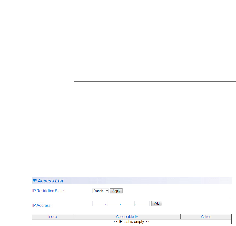
2. From the System folder, select IP Access List. The IP Access List
Page is displayed. See Figure 6.
.
Figure 6. IP Access List Page
3. Enter an IP address in the IP Address field using a xxx.xxx.xxx.xxx
format.
4. Click Add.
The IP address is added to the IP Access List table in the Accessible
IP column.

AT-GS950/24 Web Interface User Guide
29
Note
You can add up to 10 IP address to the IP Access List table.
Chapter 2: Basic Switch Configuration
30
5. From the IP Restriction Status field, select one of the following
choices from the pull-down menu:
Enable - This selection restricts the access to the AT-S109
Version 1.1.0 management software to the IP addresses in the
table listed under Accessible IP.
Disable - This selection allows unrestricted access to the AT-S109
Version 1.1.0 management software.
6. Click Apply.
Access to the management software is now restricted to those IP
addresses listed in the IP Access List table.
7. From the main menu on the left side of the page, select Save
Configuration to Flash to permanently save your changes.
Delete an IP
Address List
Entry
To delete an IP address from the IP Access List, perform the following
procedure:
1. From the main menu on the left side of the page, click the System
folder.
The System folder expands.
2. From the System folder, select IP Access List.
The IP Access List Page is displayed. See Figure 6 on page 28.
3. Select Delete next to the IP address that you want to remove.
The IP address is removed from the IP Access List table. If you
remove the last IP address from the table, the IP Restriction Status
field is set to Disable.
4. From the main menu on the left side of the page, select Save
Configuration to Flash to permanently save your changes.

AT-GS950/24 Web Interface User Guide
31
System Time
The procedures in this section describe how to configure the system time
by manually entering the time or through SNTP and how to configure the
daylight savings time feature. See the following sections:
“Manually Setting System Time” on page 31
“Setting SNTP” on page 32
“Setting Daylight Savings Parameters” on page 33
Manually Setting
System Time
To set the system time manually, perform the following procedure:
1. From the main menu on the left side of the page, click the System
folder.
The System folder expands.
2. From the System folder, select System Time.
The System Time Page is displayed. See Figure 7.
Figure 7. System Time Page
Chapter 2: Basic Switch Configuration
32
3. Use the pull down menu to set the Clock Mode parameter to
Local time.
4. In the Local Time Settings section, set the Date Setting
(YYYY:MM:DD) to the current date in the YYYY:MM:DD format.
5. In the Local Time Settings section, set the Time Settings
(HH:MM:SS) to the current time in the HH:MM:SS format.
6. Click the Apply button at the bottom of the page.
The time will take effect immediately.
7. Save your new settings or any changes to the configuration file by
selecting Save Configuration to Flash from the main menu on the left
side of the page.
Setting SNTP To configure SNTP, perform the following procedure:
1. From the main menu on the left side of the page, click the System
folder.
The System folder expands.
2. From the System folder, select System Time.
The System Time Page is displayed. See Figure 7 on page 31.
3. Use the pull down menu to set the Clock Mode parameter to SNTP.
4. Enter the IP address of the SNTP Primary Server. The format is
xxx.xxx.xxx.xxx.
5. Enter the IP address of the SNTP Secondary Server. The format is
xxx.xxx.xxx.xxx.
6. Enter the SNTP Poll Interval. The range is 1 - 60 minutes.
7. Enter the local Time Zone from the pull down menu.
8. Click the Apply button at the bottom of the page.
The switch will immediately start polling the SNTP primary server for
time information.
9. Save your new settings or any changes to the configuration file by
selecting Save Configuration to Flash from the main menu on the left
side of the page.
AT-GS950/24 Web Interface User Guide
33
Setting Daylight
Savings
Parameters
If you want to configure the switch for daylight savings time, perform the
following procedure:
1. From the main menu on the left side of the page, click the System
folder.
The System folder expands.
2. From the System folder, select System Time.
The System Time Page is displayed. See Figure 7 on page 31.
3. In the Daylight Savings Time Status field, select Enabled.
4. Specify the Month, Day, Hour and Minute when Daylight Savings will
take effect in the From time fields.
5. Specify the Month, Day, Hour and Minute when Daylight Savings will
end in the To time fields.
6. Using the pull down menu, specify the Daylight Savings offset in the
DST Offset field. You can select either 1 hr or 1/2 hr.
7. Save your new settings or any changes to the configuration file by
selecting Save Configuration to Flash from the main menu on the left
side of the page.

Chapter 2: Basic Switch Configuration
34
DHCP and ATI Web Discovery Tool
The AT-GS950/24 Gigabit Ethernet Smart switch is managed through a
web browser interface only. The factory default IP address is 192.168.1.1.
The switch does not have a local console connector, which means that
you cannot learn what the switch’s management IP address is on a web
browser without first knowing what the address is. Once the IP address is
known, you can enter it in the browser.
When the DHCP feature is enabled, a DHCP server automatically assigns
an IP address which is not advertised over the network. As a
consequence, you do not know what IP address has been assigned to the
switch.
Note
The new IP address assignment from the DHCP server may take
one to two minutes before the process is completed.
Fortunately, there is an ATI Web Discovery Tool available that resolves
this issue. It detects the MAC address, IP address and other information of
the AT-GS950 series switches that are present on your local area
network.
Note
The ATI Web Discovery Tool is available for download on the
AT-GS950/24 product page at alliedtelesis.com.

AT-GS950/24 Web Interface User Guide
35
DHCP Client Configuration
This procedure explains how to activate and deactivate the DHCP client
on the AT-GS950/24 switch. When the client is activated, the switch
obtains its IP configuration including an IP address and subnet mask from
a DHCP server on your network. Before performing the procedure, note
the following:
By default, the DHCP client is disabled on the switch.
The DHCP client supports DHCP Auto Configuration Settings or
BOOTP. See “DHCP Auto Configuration” on page 37 for more
information.
After you enable DHCP, your current management session ends
because a different IP address is assigned to the switch by the
DHCP server. The new IP address can be discovered using the
ATI Discovery Tool. See “DHCP and ATI Web Discovery Tool” on
page 34 for more information.
To activate or deactivate the DHCP client on the switch, perform the
following procedure:
1. From the main menu on the left side of the page, click the System
folder.
The System folder expands.
2. From the System folder, select IP Setup.
The IP Setup Page is shown in Figure 5 on page 26.
3. From the pull-down menu next to the DHCP Mode field, select Enable
or Disable.
4. Click Apply.
When the DHCP client is Enabled, the web server connection to the
switch is lost because a different IP address is assigned to the switch
by the DHCP server.
Caution
Enabling DHCP may end your current management session.
5. Use the ATI Web Discovery Tool to find the new IP address assigned
to the switch by the DHCP server. See “DHCP and ATI Web Discovery
Tool” on page 34 for more information.

Chapter 2: Basic Switch Configuration
36
Note
The ATI Web Discovery Tool is available for download on the
AT-GS950/24 product page at alliedtelesis.com.
6. Follow the procedure to log on with the new IP address provided by
the DHCP Server as described in “Establishing a Remote Connection
to the Web Browser Interface” on page 20.
7. Save your new settings or any changes to the configuration file by
selecting Save Configuration to Flash from the main menu on the left
side of the page.
If you do not save the new configuration when DHCP is enabled, the
software reverts to the previously saved IP address value when the
switch is power cycled or rebooted. If no IP address has been
previously saved, the IP address value reverts to 192.168.1.1.
If you enable DHCP and then save your configuration, you are saving
the DHCP setting (Enabled). The next time the switch boots up, it will
use the DHCP process to establish the IP address used to manage the
AT-GS950/24 switch.
If you enter a new IP address after disabling DHCP and save your
configuration, the DHCP setting (Disabled) and the new IP address on
the switch is saved. The next time the switch boots up, it will respond
to the IP address that you entered when you re-establish contact with
the AT-S109 Version 1.1.0 Management software.

AT-GS950/24 Web Interface User Guide
37
DHCP Auto Configuration
If you need to automatically update the switch’s configuration files via a
remote server, the DHCP Auto Configuration feature is available for this
purpose via the DHCP server.
Note
You must enable the DHCP client so that this feature can operate
with the DHCP server. See “DHCP Client Configuration” on page 35
for more information.
To configure this feature on the switch, perform the following procedure:
1. From the main menu on the left side of the page, click the System
folder.
The System folder expands.
2. From the System folder, select System.
The DHCP Auto Configuration Settings Page is shown in Figure 8.
Figure 8. DHCP Auto Configuration Settings Page
3. From the Auto Configuration State field, select one of the following
choices from the pull-down menu:
Enable - The DHCP Auto Configuration feature is active.
Note
You must enable the DHCP client so that this feature can operate
with the DHCP server. See “DHCP Client Configuration” on page 35
for more information.
Disable - The DHCP Auto Configuration feature is inactive.
4. Click Apply.
The DHCP Auto Configuration setting that you have selected is now
active.
5. From the main menu on the left side of the page, select Save
Configuration to Flash to permanently save your changes.

Chapter 2: Basic Switch Configuration
38
System Management Information
This section explains how to assign a name, location, and contact
information for the AT-GS950/24 switch. This information helps in
identifying each specific AT-GS950/24 switch among other switches in the
same local area network. Entering this information is optional.
Note
Allied Telesis recommends that you assign a name to the switch.
Naming each switch can help you identify the specific switch you
want to manage among others. It can also help to avoid performing
a configuration procedure on the wrong switch.
To set a switch’s administration information, perform the following
procedure:
1. From the main menu on the left side of the page, click the System
folder.
The System folder expands.
2. From the System folder, select Management.
The Management Page is displayed. See Figure 9 for the
AT-GS950/24 Management Page.
Figure 9. AT-GS950/24 Management Page
3. Configure the following parameters as necessary:
System Description - Specifies the Allied Telesis switch model.
You cannot change this parameter.
System Object ID - Indicates the unique SNMP MIB object
identifier that identifies the switch model. You cannot change this
parameter.
AT-GS950/24 Web Interface User Guide
39
System Name - Specifies a name for the switch, for example,
Sales. The name is optional and may contain up to 15 characters.
System Location - Specifies the location of the switch. The
location is optional and may contain up to 30 characters.
System Contact - Specifies the name of the network administrator
responsible for managing the switch. This contact name is optional
and may contain up to 30 characters.
4. Click Apply.
5. From the main menu on the left side of the page, click on Switch Info.
The Switch Information page is displayed. See “AT-GS950/24 Switch
Information Page” on page 21 for more information.
6. From the main menu on the left side of the page, select Save
Configuration to Flash to permanently save your changes.

Chapter 2: Basic Switch Configuration
40
User Name and Password Configuration
Password protection is always enabled for access to the AT-S109 Version
1.1.0 Management software. This section explains how to create new
users names and passwords and how to modify or delete existing users
for the web interface. See the following sections:
“Add New User Name and Password” on page 40
“Modify User Name and Password” on page 41
“Delete User Name and Password” on page 42
Add New User
Name and
Password
The default User Name and Password is “manager” and “friend” - both
without the quotes. To configure new User Name and Password
information, perform the following procedure:
1. From the main menu on the left side of the page, click the System
folder.
The System folder expands.
2. From the System folder, select Administration.
The Administration Page is displayed. See Figure 10.
Figure 10. Administration Page
3. To create a user name, enter a user name in the box next to the User
Name field.
You can enter a value of up to 12 alphanumeric characters. The User
Name field is case sensitive.

AT-GS950/24 Web Interface User Guide
41
4. To add a password that corresponds to the user name entered in
step 3, enter a password of up to 12 alphanumeric characters in the
box next to the Password field. The Password field is case sensitive.
5. To confirm the password entry, retype the password in the box next to
the Confirm Password field.
6. Click Add to activate your changes on the switch.
7. From the main menu on the left side of the page, select Save
Configuration to Flash to permanently save your changes.
Modify User
Name and
Password
To modify the a user name password, perform the following procedure:
1. From the main menu on the left side of the page, click the System
folder.
The System folder expands.
2. From the System folder, select Administration.
The Administration Page is shown in Figure 10 on page 40.
3. Identify the user name that you want to change and click Modify in the
Action column.
The Modify Administration Page is displayed. See Figure 11.
Note
The default user name cannot be modified or deleted. The default
password can be modified.
Figure 11. Modify Administration Page
4. To change a password, enter a password of up to 12 alphanumeric
characters in the box next to the Password field.
5. To confirm the above password, retype the password in the box next to
the Confirm Password field.
6. Click Apply to activate your changes on the switch.
7. From the main menu on the left side of the page, select Save
Configuration to Flash to permanently save your changes.

Chapter 2: Basic Switch Configuration
42
Delete User Name
and Password
To delete a user name that you have previously added, perform the
following procedure.
1. From the main menu on the left side of the page, click the System
folder.
The System folder expands.
2. From the System folder, select Administration.
The Administration Page is shown in Figure 10 on page 40.
3. Identify the user name that you want to delete and click Delete.
The user name is removed from the Administration table.
Note
The default user name cannot be modified or deleted. The default
password can be modified.
4. From the main menu on the left side of the page, select Save
Configuration to Flash to permanently save your changes.

AT-GS950/24 Web Interface User Guide
43
User Interface Configuration
This procedure explains how to enable and disable the user interfaces on
the switch. With this procedure you can enable or disable the AT-GS950/
24 SNMP Agent. For more information about SNMP, go to Chapter 20,
“Simple Network Management Protocol SNMPv1 and v2c” on page 265
and Chapter 21, “Simple Network Management Protocol SNMPv3” on
page 275.
Note
The Web Server Status is displayed as Enabled for your
information only. The Web Server cannot be disabled.
SNMP Interface To enable or disable the AT-GS950/24 SNMP interface, perform the
following procedure:
1. From the main menu on the left side of the page, click the System
folder.
The System folder expands.
2. From the System folder, select User Interface.
The User Interface Page is displayed. See Figure 12.
Figure 12. User Interface Page
3. Choose Enable or Disable from the pull down list for the SNMP Agent
parameter.
Enabled - When you enable this parameter, the SNMP agent is
active. You can manage the AT-GS950/24 switch with Network
Management Software and the switch’s private MIB.
Disabled - When you enable this parameter, the SNMP agent is
inactive.

Chapter 2: Basic Switch Configuration
44
Note
See Chapter 20, “Simple Network Management Protocol SNMPv1
and v2c” on page 265 and Chapter 21, “Simple Network
Management Protocol SNMPv3” on page 275 to configure the
remaining SNMP parameters.
4. Click Apply located under the Web Server Status Enable/Disable
field.
5. From the main menu on the left side of the page, select Save
Configuration to Flash to permanently save your changes.
User Interface
Timeout
To set the Web Idle Timeout, perform the following procedure:
1. From the main menu on the left side of the page, click the System
folder.
The System folder expands.
2. From the System folder, select User Interface.
The User Interface Page is displayed. See Figure 12 on page 43.
3. Refer to the bottom portion of the web page. Enter the Web Idle
Timeout parameter. The range is from 3 to 60 minutes.
4. From the main menu on the left side of the page, select Save
Configuration to Flash to permanently save your changes.

AT-GS950/24 Web Interface User Guide
45
System Information Display
The Switch Information page is initially displayed when you first log into
the AT-GS950/24 switch. It provides general information about the switch.
To view this information, perform the following procedure:
1. From the main menu on the left side of the page, select Switch Info.
The Switch Information Page is displayed. See Figure 13.
Figure 13. AT-GS950/24 Switch Information Page
The Switch Information Page displays the following information:
System Up For - The number of days, hours, and minutes that the
switch has been running since it was last rebooted.
Runtime Image - The version number of the runtime firmware.
Boot Loader - The version number of the bootloader firmware.
Hardware Information Section:
Version - The hardware version number.
DRAM Size - The size of the DRAM, in megabytes.
Flash Size - The size of the flash memory, in megabytes.
Chapter 2: Basic Switch Configuration
46
Administration Information Section:
Switch Name - This parameter displays the name assigned to the
switch. To assign the switch a name, refer to “System
Management Information” on page 38.
Switch Location - This parameter displays the location of the
switch. To assign the location, refer to “System Management
Information” on page 38.
Switch Contact - This parameter displays the contact person
responsible for managing the switch. To assign the name of a
contact, refer to “System Management Information” on page 38.
System MAC Address, IP Address, Subnet Mask, and Gateway
Section:
MAC Address - This parameter displays the MAC address of the
switch.
IP Address - This parameter displays the system IP address.
Refer to “Configuration of IP Address, Subnet Mask and Gateway
Address” on page 26 to manually assign an IP address or “DHCP
Client Configuration” on page 35 to activate the DHCP client.
Subnet Mask - This parameter displays the subnet mask for the
switch. Refer to “Configuration of IP Address, Subnet Mask and
Gateway Address” on page 26 to manually assign a subnet mask
or “DHCP Client Configuration” on page 35 to activate the DHCP
client.
Default Gateway - This parameter displays the default gateway IP
address. Refer to “Configuration of IP Address, Subnet Mask and
Gateway Address” on page 26 to manually assign a gateway
address or “DHCP Client Configuration” on page 35 to activate the
DHCP client.
Automatic Network Features Section:
DHCP Mode - This parameter displays the status of the DHCP
client on the switch. For information about setting this parameter,
refer to “DHCP Client Configuration” on page 35.

AT-GS950/24 Web Interface User Guide
47
Switch Reboot
You can reboot the AT-GS950/24 switch by either pressing the front panel
eco-friendly switch between 5 to 9 seconds or by using the Normal reboot
function provided in the AT-S109 Version 1.1.0 management software.
In addition to rebooting the switch, you have the option to reset the
AT-GS950/24 switch configuration parameters to the original factory
default settings. There are two ways to accomplish this:
Press the front panel ecofriendly button for more than 10 seconds
and release it.
Reboot the switch in the AT-S109 Version 1.1.0 management
software and follow the procedures to reset to factory defaults. See
“Switch Reboot” on page 48 and “Configure Factory Default
Values” on page 49 for more information.
Note
Refer to the AT-GS950 Installation guide for more information about
how to use the eco-friendly button to reboot or reset the switch.
Note
The AT-S109 Version 1.1.0 Management software default values
are listed in “AT-GS950/24 Default Parameters” on page 349.
Password
Protection of
Factory Reset
If your switch is located in a controlled environment such as a locked
switching closet or limited access equipment room, it may be desirable to
have the ability to easily reset the switch to factory defaults at any time by
using either the front panel ecofriendly switch or the AT-S109 Version
1.1.0 management software.
However, if your switch is installed in an uncontrolled environment, you
may want to protect the switch’s configuration from unwanted or accidental
resets. The AT-S109 Version 1.1.0 management software allows you to
disable the factory default reset feature and lock it with your own
password. When this is done, two areas are affected:
The reset and factory default reset features on the front panel
ecofriendly switch are disabled.
The factory default reset feature in the AT-S109 Version 1.1.0
management software is disabled. However, you can still reset the
switch via the management software without affecting the switch’s
configuration.
The factory default reset can be enabled again by using the password that
you initially defined when disabling this function.

Chapter 2: Basic Switch Configuration
48
Caution
Since you define this password as part of the process of disabling
this function, Allied Telesis has no knowledge of it. You are
responsible for keeping the password in a safe place. If it is lost,
Allied Telesis does not have a way to help you recover it.
See “Disabling Factory Default Reset Feature” on page 51 for information
about how to disable the factory default reset feature.
Switch Reboot The following procedure outlines how to reboot your AT-GS950/24 switch.
Caution
This procedure reboots the switch and reloads the AT-S109 Version
1.1.0 Management software configuration from flash memory.
Insure that your current configuration is saved before rebooting the
switch by selecting Save Configuration to Flash from the main
menu on the left side of the page to permanently save your changes.
All configuration parameters that have not been previously saved
are lost. After the switch is reboots, they are reset to the values
stored in the flash memory.
Caution
This procedure causes the switch to reboot. The switch does not
forward network traffic during the reboot process. Some network
traffic may be lost.
1. From the main menu on the left side of the page, select the Tools
folder.
The Tools folder expands.
2. From the Tools folder, select Reboot.
The Factory Default Reset/Reboot Page is displayed. See Figure 14.
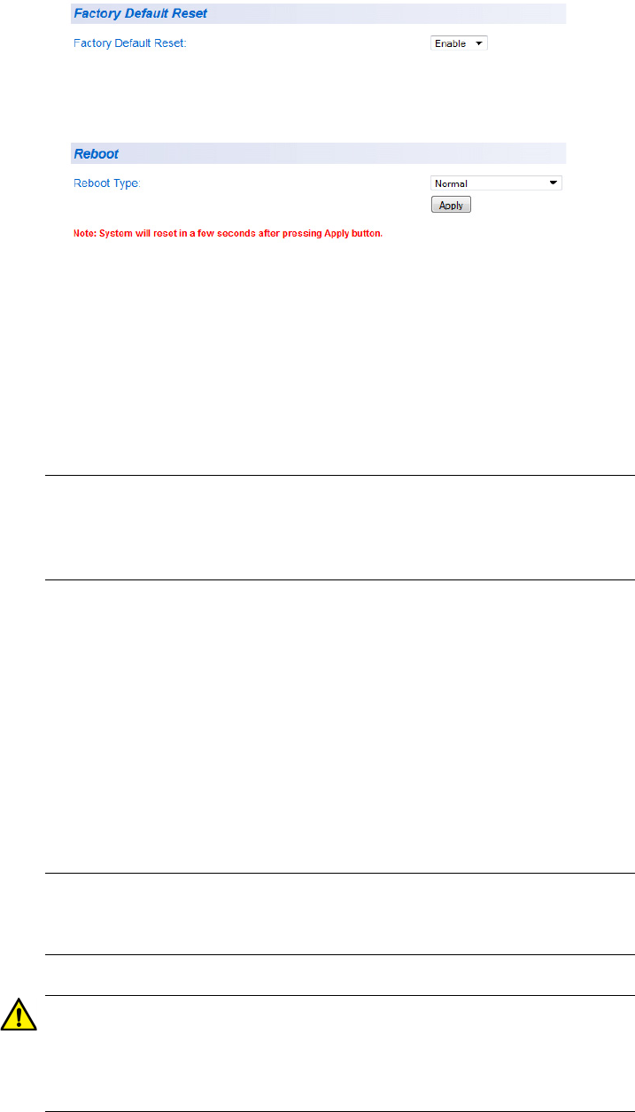
AT-GS950/24 Web Interface User Guide
49
Figure 14. Factory Default Reset/Reboot Page
3. Go to the lower part of the page to the Reboot section.
4. In the Reboot Type field, select Normal from the pull-down menu.
When the switch is rebooted with this selection, all configuration
parameters that are saved in flash memory are loaded into the switch’s
active memory.
Note
Two additional options are available in the Reboot Type field. The
procedures for these options are described in "Configure Factory
Default Values".
5. Click Apply.
The switch immediately begins to reload the AT-S109 Version 1.1.0
Management software and configuration parameters. This process
takes approximately two minutes to complete. You can not manage the
device during the reboot. After the reboot is finished, you can log in
again if you want to continue to manage the switch.
Configure
Factory Default
Values
This procedure returns all AT-S109 Version 1.1.0 Management software
parameters to their factory default values and deletes all tagged and port-
based VLANs on the switch.
Note
The AT-S109 Version 1.1.0 Management software factory default
values are listed in “AT-GS950/24 Default Parameters” on page 349.
Caution
This procedure causes the switch to reboot. The switch does not
forward network traffic during the reboot process. Some network
traffic may be lost.

Chapter 2: Basic Switch Configuration
50
To return the AT-S109 Version 1.1.0 Management software to the default
settings, perform the following procedure:
Note
See “AT-GS950/24 Default Parameters” on page 349 for the specific
factory default values.
1. From the main menu on the left side of the page, select the Tools
folder.
The Tools folder expands.
2. From the Tools folder, select Reboot.
The Reboot Page is displayed. See Figure 14 on page 49.
3. Go to the lower part of the page to the Reboot section.
4. In the Reboot Type field, use the pull-down menu to select one of the
following options:
Normal - This setting reloads all configuration parameters that are
saved in flash memory. See “Switch Reboot” on page 48 for more
information when using this selection.
Factory Default - Resets all switch parameters to the factory
default settings, including the IP address, subnet mask, and
gateway address.
Caution
This setting will cause the IP address to be reset to 192.168.1.1.
You will loose connectivity with the switch management software
after the reboot is completed and you can login again with this IP
address.
Factory Default Except IP Address - Resets all switch parameters to
the factory default settings, but retains the current IP address, subnet
mask, and gateway settings saved in flash memory. If the DHCP client
is enabled, it remains enabled after this reset and assignment of the IP
address, subnet mask, and gateway settings are managed by the
DHCP server.
5. Click Apply.
The switch begins the reboot process. You must wait approximately
two minutes for the switch to complete the reboot process before you
can re-establish your management session and network traffic begins
flowing normally again.
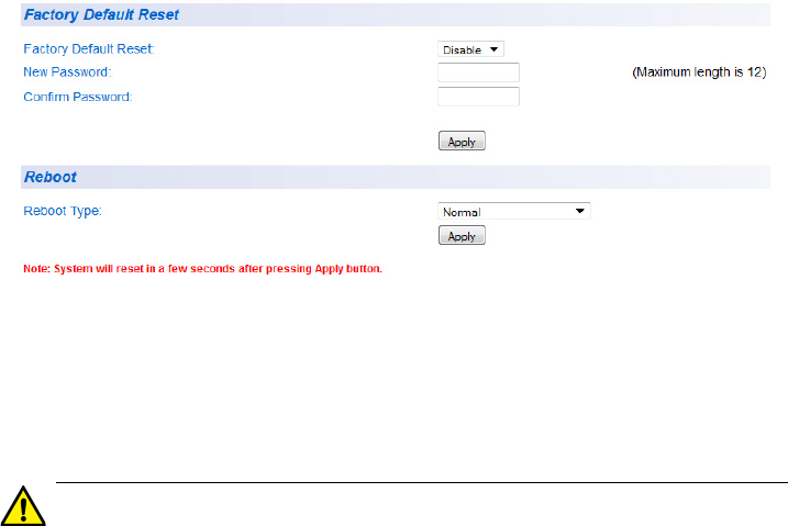
AT-GS950/24 Web Interface User Guide
51
Disabling Factory
Default Reset
Feature
The factory default reset feature allows anyone to reset the switch to the
factory default configuration. You may disable this feature. More details
are available concerning “Password Protection of Factory Reset” on
page 47.
To disable the factory default reset feature, perform the following
procedure:
1. From the main menu on the left side of the page, select the Tools
folder.
The Tools folder expands.
2. From the Tools folder, select Reboot.
The Factory Default Reset/Reboot Page is displayed. See Figure 14
on page 49.
3. Go to the Factory Default Reset section on the upper part of the page.
You will find a field called Factory Default Reset. This selection
allows you to reset the switch configuration to the factory default
settings given in “MSTP Overview” on page 329 by using the Reboot
procedures outlined in “Configure Factory Default Values” on page 49.
4. To disable the factory default reset feature, select Disable on the pull-
down menu of the Factory Default Reset field.
The Factory Default Reset/Reboot Page changes to include fields for
entering a password. See Figure 15.
Figure 15. Factory Default Reset/Reboot Page with Password Entry
5. In the New Password field, enter a password of up to 12 characters in
length. It is case-sensitive. There is not a default password for this
field.
Caution
Since you define this password as part of the process of disabling
this function, Allied Telesis has no knowledge of it. You are

Chapter 2: Basic Switch Configuration
52
responsible for keeping the password in a safe place. If it is lost,
Allied Telesis does not have a way to help you recover it.
6. Re-enter the same password in the Confirm Password field.
7. Click Apply.
The following message is displayed:
By clicking on Accept, the Factory Default Reset function will be
Disabled on both the switch management software and the
physical front panel ecoFriendly button. If you loose this password,
ATI cannot recover it for you.
By Clicking on Cancel, the “Factory Default Reset” function will
remain Enabled on both the switch management software and the
physical front panel ecoFriendly button.
8. Click Accept.on the message.
The Factory Default Reset page changes and displays the Factory
Default Reset feature as Disabled. See Figure 16.
Figure 16. Factory Default Reset Disabled Page
9. From the main menu on the left side of the page, select Save
Configuration to Flash to permanently save your changes.
Enabling Factory
Default Reset
If the Factory Default Reset feature is disabled and you choose to
Enable it, perform the following procedure:
1. From the main menu on the left side of the page, select the Tools
folder.
The Tools folder expands.
2. From the Tools folder, select Reboot.
The Factory Default Reset/Reboot Page is displayed. See Figure 16.
3. Go to the Factory Default Reset section on the upper part of the page.
The Factory Default Reset field should be set to Disable.

AT-GS950/24 Web Interface User Guide
53
Note
If the Factory Default Reset field is already set to Enable, you do
not need to continue with this procedure.
4. To enable the factory default reset feature, select Enable on the pull-
down menu of the Factory Default Reset field.
The Factory Default Reset/Reboot Page changes to include a
Password field for entering a password. See Figure 17 on page 53.
Figure 17. Factory Default Reset/Reboot Page with Password Entry
5. Enter the same password that you defined when you previously set the
Factory Default Reset field to Disable.
6. Click Apply.
The initial Factory Default Reset/Reboot Page is displayed with the
Factory Default Reset field Enabled. See Figure 14 on page 49.
In the Reboot section, the Reboot Type field now includes the options
presented in its pull down menu for returning the switch configuration
to the factory default values. See “Configure Factory Default Values”
on page 49 for more information.
7. From the main menu on the left side of the page, select Save
Configuration to Flash to permanently save your changes.

Chapter 2: Basic Switch Configuration
54
Pinging a Remote System
This procedure instructs the AT-GS950/24 switch to ping a node on your
network. This procedure is useful in determining whether an active link
exists between the switch and another network device.
Note
The device you are pinging must be a member of the Default VLAN
and within the same local area network as your switch. In other
words, the port on the switch through which the node is
communicating with the switch must be an untagged or tagged
member of the Default VLAN.
To ping a network device, perform the following procedure:
1. From the main menu on the left side of the page, select the Tools
folder.
The Tools folder expands.
2. From the Tools folder, select Ping.
The Ping Test Configuration Page is displayed. See Figure 18.
Figure 18. Ping Test Configuration Page
3. Configure the following parameters:
Destination IP Address - The IP address of the node you want to
ping in the xxx.xxx.xxx.xxx format.
Timeout Value - Specifies the length of time, in seconds, the
switch waits for a response before assuming that a ping has failed.
Number of Ping Requests - Specifies the number of ping
requests you want the switch to perform.
4. Click Start.

AT-GS950/24 Web Interface User Guide
55
5. To view the ping results, click Show Ping Results.
A sample Ping Test Results Page is displayed. See Figure 19.
Figure 19. Ping Test Results Page
The following information is displayed:
Destination IP Address - Indicates the IP address of the unit that
receives the ping.
Pass - Indicates the percentage of times the ping passed.
Average Time - Indicates the time, in milliseconds, the ping was
received.
6. Click Back to Ping Test to return to the Ping Test Configuration Page.

Chapter 2: Basic Switch Configuration
56
SSL Settings
The AT-GS950/24 switch has a web browser server for remote
management of the unit with a web browser application from management
workstations on your network. By default, the server operates in a
non-secure HTTP mode and can be configured to communicate in a
secure HTTPS mode with SSL protocol.
In many situations, the communication with the switch will be in a
controlled environment and it is acceptable to communicate with the
management software in the HTTP mode.
However, you may find that your management communications are
subject to outside security risks and web sessions conducted in the non-
secure HTTP mode are vulnerable to security issues because the packets
are sent in clear text. Web browser management sessions that use the
secure HTTPS mode with SSL protocol are protected against snooping
because the packets exchanged between the switch and your
management workstations are encrypted. When operating in this mode,
only the AT-GS950/24 switch and the web browser are able to decipher
the packets sent and received between them.
Configuring SSL To enable or disable the SSL protocol feature, perform the following
procedure:
1. From the main menu on the left side of the page, click the System
folder.
The System folder expands.
2. From the System folder, select SSL Settings.
The SSL Settings Page is displayed. See Figure 20.
Figure 20. SSL Settings Page
3. From the SSL Settings field, select one of the following choices from
the pull-down menu:
Enable - The secure SSL mode is active. You must log in to the
switch’s management using the HTTPS mode on your browser.
Disable - The secure SSL mode is inactive. You must log in to the
switch’s management using the HTTP mode on your browser.
AT-GS950/24 Web Interface User Guide
57
4. Click Apply.
The SSL setting that you have selected is now active.
5. From the main menu on the left side of the page, select Save
Configuration to Flash to permanently save your changes.

Chapter 2: Basic Switch Configuration
58
System Log Configuration
The System log is designed to monitor the operation the AT-GS950/24
switch by recording the event messages it generates during normal
operation. These events may provide vital information about system
activity that can help in the identification and solutions of system
problems.
To configure the System log, perform the following procedure:
1. From the main menu on the left side of the page, click the System
folder.
The System folder expands.
2. From the System folder, select System Log Configuration.
The System Log Configuration Page is displayed. See Figure 21.
Figure 21. System Log Configuration Page
AT-GS950/24 Web Interface User Guide
59
3. From the Syslog Status field, select one of the following choices from
the pull-down menu:
Enable - The System log is active.
Disable - The System log is inactive.
4. From the Time Stamp field, select one of the following choices from the
pull-down menu:
Enable - Each event message recorded in the log will have a time
stamp recorded with it.
Disable - No time stamp will be recorded with the event messages.
5. Enter the Messages Buffer Size.The range is between 1 and 200.
6. Enter the Syslog Server IP Address. The format is xxx.xxx.xxx.xxx. If
the address is left at the default setting of 0.0.0.0, no server is
specified.
7. In the Facility field, enter the Facility local from the pull-down menu.
The choices range from local0 through local7.
8. Select the Logging Level. This parameter specifies what level of
event messages will be logged into the System log. Your choices are
as follows:
0 Emergency - The system is unusable.
1 Alert - Action must be taken immediately.
2 Critical - Critical conditions are displayed.
3 Error - Error conditions are displayed.
4 Warning - Warning conditions are displayed.
5 Notice - Normal but significant conditions are displayed.
6 Informational - Informational messages are displayed
7 Debug - Debug-level messages are displayed.
9. Click Apply.
The System log is now active.
10. From the main menu on the left side of the page, select Save
Configuration to Flash to permanently save your changes.
Chapter 2: Basic Switch Configuration
60

61
Chapter 3
Port Configuration
This chapter provides a description of the physical characteristics of the
ports and a procedure that explains how to view and change the port
settings. This chapter includes the following sections:
“Overview” on page 62
“Display and Configure Ports” on page 63
Note
To permanently save your new settings or any changes to the
configuration file, select Save Configuration to Flash from the main
menu on the left side of the page.

Chapter 3: Port Configuration
62
Overview
This chapter describes how to display and modify the physical
characteristics of an AT-GS950/24 switch. You can display and modify the
settings of all the ports on one web page. The port characteristics that are
displayed are:
Trunk Group Number
Port type
Link Status
Admin Status
Duplex Mode
Jumbo frame
Flow control
EAP Pass
BPDU frame
These characteristics are described in the next section.
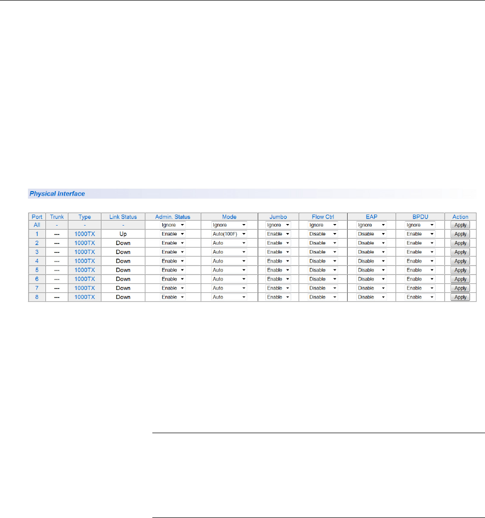
AT-GS950/24 Web Interface User Guide
63
Display and Configure Ports
This procedure explains how to configure the ports on the
AT-GS950/24 switch using the Port Configuration Page. This page allows
you to view and configure the parameter settings of individual or all the
switch ports at one time.
To configure the ports, perform the following procedure:
1. From the main menu on the left side of the page, select Physical
Interface.
A partial view of the AT-GS950/24 Physical Interface Page is displayed
in Figure 22.
Figure 22. AT-GS950/24 Physical Interface Page
2. Adjust the port settings as needed. Not all parameters are adjustable.
The parameters are defined as follows:
Port - Specifies the port number. The All value indicates ports 1
through 24 on the AT-GS950/24 switch. You cannot change this
parameter.
Note
You can use the All row value in the Port column to set the Admin.
Status, Mode, Jumbo, Flow Ctrl, EAP Pass, and BPDU fields to
the same values for all ports at the same time. In the All row when
you select Ignore, Enable or Disable in one of these columns, it
applies to all of the AT-GS950/24 switch ports.
Trunk - This parameter indicates the trunk group number. A
number in this column indicates that the port has been added to a
trunk. This parameter can not be configured on this page,
However, for information about configuring a trunk, refer to Chapter
10, “Static Port Trunking” on page 147.
Type - Indicates the port type. On the AT-GS950/24, the port type
Chapter 3: Port Configuration
64
is 1000TX for 10/100/1000Base-T twisted-pair ports (1 through 20,
21R through 24R) and 100FX or 1000TX for the SFP ports (21
through 24) for copper or fiber SFP type.
Link Status - This parameter indicates the status of the link
between the port and the end node connected to the port. The
possible values are:
Up -This parameter i Indicates a valid link exists between the
port and the end node.
Down -This parameter i Indicates the port and the end node
have not established a valid link.
Admin. Status -This parameter indicates the operating status of
the port. You can use this parameter to enable or disable a port.
You may want to disable a port and prevent packets from being
forwarded if a problem occurs with the node or cable connected to
the port. You can enable the port to resume normal operation after
the problem has been fixed. You can also disable an unused port
to secure it from unauthorized connections. The possible values
are:
Ignore -This parameter applies to the All row only and i
Indicates that the Admin. Status field must be set individually
for each port.
Enabled - This parameter indicates the port is able to send and
receive Ethernet frames.
Disabled - This parameter indicates the port is not able to send
and receive Ethernet frames.
Jumbo -This parameter i Indicates whether or not jumbo frames
can be accepted by the switch. You may want to activate jumbo
frames when your switch will transmit video and audio files. The
possible values are:
Ignore -This parameter i Indicates that the All setting does not
apply to the Jumbo field. In other words, each port is set
individually.
Enabled -This parameter i Indicates the port is permitted to
accept jumbo frames.
Disabled -This parameter i Indicates the port is not permitted to
accept jumbo frames.

Chapter 3: Port Configuration
66
Mode -This parameter i Indicates the speed and duplex mode
settings for the port. You can use this parameter to set the speed
and duplex mode of a port. The possible settings are:
Ignore -This parameter i Indicates that the All setting does not
apply to the Mode field. In other words, each port is set
individually.
Auto -This parameter i Indicates the port is using Auto-
Negotiation to set the operating speed and duplex mode. The
actual operating speed and duplex mode of the port are
displayed in parentheses (for example, “1000F” for 1000 Mbps
full duplex mode) after a port establishes a link with an end
node.
Auto (1000F) -This parameter i Indicates the port is configured
for 1000Mbps operation in Auto-Negotiation mode.
1000/Full -This parameter i Indicates the port is configured for
1000Mbps operation in full-duplex mode.
100/Full -This parameter i Indicates the port is configured for
100Mbps operation in full-duplex mode.
10/Full -This parameter i Indicates the port is configured for
10Mbps operation in full-duplex mode.
1000/Half -This parameter i Indicates the port is configured for
1000Mbps operation in half-duplex mode.
100/Half -This parameter i Indicates the port is configured for
100Mbps operation in half-duplex mode.
10/Half -This parameter i Indicates the port is configured for
10Mbps operation in half-duplex mode.
When selecting a Mode setting, the following points apply:
When a twisted-pair port is set to Auto-Negotiation, the end node
should also be set to Auto-Negotiation to prevent a duplex mode
mismatch. A switch port using Auto-Negotiation defaults to half-
duplex if it detects that the end node is not using Auto-Negotiation.
This can result in a mismatch if the end node is operating at a fixed
duplex mode of full-duplex. To avoid this problem when connecting
an end node with a fixed duplex mode of full-duplex to a switch
port, disable Auto-Negotiation on the port and set the port’s speed
and duplex mode manually.
The only valid setting for the SFP ports is Auto-Negotiation.
Flow Control - This parameter reflects the current flow control
setting on the port. The switch uses a special pause packet to
notify the end node to stop transmitting for a specified period of
time. The possible values are:
AT-GS950/24 Web Interface User Guide
67
Ignore - This parameter indicates that the All setting does not
apply to the Flow Control field. In other words, each port is set
individually.
Enabled - This parameter indicates that the port is permitted to
use flow control.
Disabled - This parameter indicates that the port is not
permitted to use flow control.
EAP Pass - This parameter reflects the current Extensible
Authentication Protocol (EAP) setting on the port. The possible
values are:
Ignore - This parameter indicates that the All setting does not
apply to the EAP Pass field. In other words, each port is set
individually.
Enabled - This parameter indicates that the port is able to send
and receive EAP packets.
Disabled - This parameter indicates that the port is disabled and
is not able to send or receive EAP packets.
BPDU - This parameter reflects the current BPDU setting on the
port.The possible values are:
Ignore - This parameter indicates that the All setting does not
apply to the BPDU field. In other words, each port is set
individually.
Enabled - This parameter indicates that the switch will pass
BPDU frames through the switch and broadcast them through all
other ports.
Disabled - This parameter indicates that the switch will not pass
BPDU frames through the switch, With RSTP or STP enabled,
the switch will receive BPDU frames and process them
according to the spanning tree protocol.
3. From the main menu on the left side of the page, select Save
Configuration to Flash to permanently save your changes.
Chapter 3: Port Configuration
68

69
Chapter 4
Port Mirroring
This chapter describes the Port Mirroring feature and the procedure for
setting up port mirroring. Port mirroring allows you to unobtrusively monitor
the ingress and egress traffic on a port by having the traffic copied to
another port. This chapter contains the following sections:
“Overview” on page 70
“Port Mirroring Configuration” on page 71
“Disable Port Mirroring” on page 73
Note
To permanently save your new settings or any changes to the
configuration file, select Save Configuration to Flash from the main
menu on the left side of the page.

Chapter 4: Port Mirroring
70
Overview
The port mirroring feature allows you to unobtrusively monitor the traffic
received and transmitted on one or more ports by copying the traffic to
another switch port. You can connect a data analyzer to the port where the
traffic is copied and monitor the traffic on the other ports without impacting
network performance or speed.
A port mirror has two component ports. The port or ports whose traffic you
want to mirror is called the source port(s). The port where the traffic will be
copied to is called the mirroring port.
Observe the following guidelines when you create a port mirror:
You can select more than one source port at a time. However, the
more ports you mirror, the less likely the mirroring port is able to
handle all the traffic. For example, if you mirror the traffic of six
heavily active ports, the destination port is likely to drop packets,
meaning that it does not provide an accurate mirror of the traffic of
the six source ports.
The source and mirror ports must be located on the same switch.
You can mirror the ingress or egress traffic of the source ports or
both.
While the Mirroring feature is enabled, the mirroring port is
dedicated to monitoring the traffic from the source ports and
cannot used for regular network operations.

AT-GS950/24 Web Interface User Guide
71
Port Mirroring Configuration
To configure Port Mirroring, perform the following procedure:
1. Select the Bridge folder.
The Bridge folder expands.
2. From the Bridge folder, select Mirroring.
The Mirroring Page is displayed. See Figure 23.
Figure 23. AT-GS950/24 Mirroring Page
3. Click the pull-down menu on the Status field and select one of the
following choices:
Enable - This parameter activates the Port Mirroring feature and
the rest of the configuration parameters become active on the
page.
Disable - This parameter de-activates the Port Mirroring feature
and the rest of the configuration parameters become inactive on
the page.
4. Click Mirroring Port and from the pull-down menu, select the port.
5. For the source port, select the port(s) whose ingress, egress, or both
ingress and egress traffic you want to monitor.
A check in a box indicates the Ingress or Egress traffic for a port has
been selected.
6. Click Apply on the right-hand side of the page.
The Port Mirroring configuration is implemented immediately on the
AT-GS950/24 switch.
You can connect a data analyzer to the mirroring port to monitor the
Ethernet traffic on the source port(s).
Chapter 4: Port Mirroring
72
7. From the main menu on the left side of the page, select Save
Configuration to Flash to permanently save your changes.

AT-GS950/24 Web Interface User Guide
73
Disable Port Mirroring
To disable Port Mirroring, perform the following procedure:
1. Select the Bridge folder.
The Bridge folder expands.
2. From the Bridge folder, select Mirroring.
The Mirroring page is shown in Figure 23 on page 71.
3. From the Status field, select Disable and click Apply.
Port mirroring is immediately disabled on the switch and the
parameters on the web page become inactive. You can now use the
mirroring port for regular network operations.
4. From the main menu on the left side of the page, select Save
Configuration to Flash to permanently save your changes.
Chapter 4: Port Mirroring
74

75
Chapter 5
Virtual LANs
This chapter contains a description of Virtual Local Area Networks
(VLANs) and the procedures for creating, modifying, and deleting both
port-based and tagged VLANs. This chapter contains the following
sections:
“VLAN Overview” on page 76
“Assign Ports to a VLAN Mode” on page 81
“Tagged VLAN Configuration” on page 83
“Port-Based VLAN Configuration” on page 91
“Modify a Port-Based VLAN” on page 92
“Delete a Port-Based VLAN” on page 92
Note
The Voice VLAN feature is not covered in this section. For more
information, see “Voice VLAN” on page 103.
Note
To permanently save your new settings or any changes to the
configuration file, select Save Configuration to Flash from the main
menu on the left side of the page.

Chapter 5: Virtual LANs
76
VLAN Overview
A virtual LAN or VLAN is a group of ports on an Ethernet switch that form
a logical Ethernet segment via the AT-S109 Version 1.1.0 Management
software. The ports of a VLAN form an independent traffic domain where
the traffic generated by the nodes of a VLAN remains within the VLAN.
With VLANs, you can segment your local area network using the AT-S109
Version 1.1.0 ’s Management software and group nodes with related
functions into their own separate, logical, VLAN segments. These VLAN
groupings can be based on similar data needs or security requirements.
For example, you can create separate VLANs for each department in your
company, such as Sales, Accounting and Engineering.
VLANs offer several important benefits:
Improved network performance
Network performance often suffers as networks grow in size and as
data traffic increases. The more nodes on each LAN segment vying for
bandwidth, the greater the likelihood overall network performance
decreases.
VLANs improve network performance because traffic stays within the
separate, logical LAN segment of the VLAN. The nodes of a VLAN
receive traffic only from nodes of the same VLAN. This reduces the
need for nodes to handle traffic that is not destined for them. It also
frees up bandwidth within all the logical workgroups.
In addition, because each VLAN constitutes a separate broadcast
domain, broadcast traffic remains within the VLAN and is not shared
with other ports of the switch that are not members of that VLAN.
Because the broadcast traffic is not shared with ports outside of the
VLAN, those non-member ports experience an overall network
performance improvement.
Increased security
Because data traffic generated by a node in a VLAN is restricted only
to the other nodes of the same VLAN, you can use VLANs to control
the flow of packets in your network and prevent packets from being
shared with unauthorized end nodes.
Simplified network management
VLANs can simplify network management. Before VLANs became a
layer 2 feature, physical changes to the network often had to been
made at the switches in the wiring closets. For example, if an
employee changed departments, changing the employee’s LAN
segment assignment might require a change to the cabling of the
switches.
AT-GS950/24 Web Interface User Guide
77
With VLANS, you can reconfigure the LAN segment assignment of an
end node connected to the AT-GS950/24 switch’s management
software. Also, you can change the VLAN memberships without
moving the workstations physically or change group memberships
without moving cables from one port to another.
In addition, a virtual LAN can span more than one switch. This means
that the end nodes of a VLAN do not need to be connected to the
same switch and so are not restricted to being in the same physical
location.
The AT-GS950/24 Gigabit Ethernet Smart Switch supports the following
types of VLANs:
Port-based VLANs
Tagged VLANs
Both types of VLANs are described in the following sections.
Port-based
VLAN Overview
As explained in the “VLAN Overview” on page 76, a VLAN consists of a
group of ports on an Ethernet switch that form an independent traffic
domain. This type of VLAN is independent of the header information
including VLAN tags in a frame. Traffic generated by the end nodes of a
VLAN remains within the VLAN and does not cross over to the end nodes
of other VLANs unless there is an interconnection device, such as a router
or Layer 3 switch.
A port-based VLAN is a group of ports on the switch that form a logical
Ethernet segment. A port-based VLAN can have as many or as few ports
as needed. The VLAN can consist of all the ports on an Ethernet switch, or
just a few ports.
There are two components of a port-based VLAN in the
AT-S109 Version 1.1.0 Management software:
VLAN Name
VLAN Index
VLAN Name
To create a port-based VLAN, you must give it a unique name. This name
can reflect the function of the network devices that are VLAN members,
such as Sales, Production, and Engineering.
VLAN Index
You must assign a unique number to each VLAN in a network. This
number is called the Port-Based VLAN Index. This number uniquely
identifies a VLAN in the AT-GS950/24 switch and across the network.
Chapter 5: Virtual LANs
78
Each port of a port-based VLAN can belong to as many VLANs as
needed. Therefore, traffic can be forwarded to the members of the groups
to which the port is assigned. For example, port 1 and port 2 are members
of group 1 and ports 1 and 3 are members of group 2. In this case, traffic
from port 1 is forwarded to ports 2 and 3, traffic from port 2 is forwarded
only to port 1, and traffic from port 3 is forwarded only to port 1.
General Rules for Creating a Port-based VLAN
Here is a summary of general rules to observe when creating a port-based
VLAN:
Assign a unique name to each port-based VLAN.
Assign a unique VLAN Index to each port-based VLAN. If a
particular port-based VLAN spans multiple switches, each part of
the VLAN on the different switches must be assigned the same
VLAN ind ex.
Create up to 52 port-based VLANs.
Tagged VLAN
Overview
The second type of VLAN supported by the AT-S109 Version 1.1.0
Management software is the tagged VLAN. In this type of VLAN,
membership is determined by tag information within the frames that are
received on a port and the VLAN configuration of each port.
The VLAN information within an Ethernet frame is referred to as a tag and
is contained in a tagged header for the frame. A tag, which follows the
source and destination addresses in a frame, contains the VLAN ID of the
VLAN to which the frame belongs (IEEE 802.3ac standard). This number
uniquely identifies each VLAN in a network.
When a switch receives a frame with a VLAN tag, referred to as a tagged
frame, the switch forwards the frame only to those ports whose VLAN ID
equals the VLAN tag.
A port that receives or transmits tagged frames is referred to as a tagged
port. Any network device connected to a tagged port must be IEEE
802.1Q-compliant. This is the standard that outlines the requirements and
standards for VLAN tagging. The device must be able to process the
tagged information on received frames and add tagged information to
transmitted frames.
A tagged VLAN consists of the following:
VLAN Index
You must assign a unique number to each tagged VLAN in a network.
This number is called the tagged VLAN ID. This number uniquely identifies
a tagged VLAN in the AT-GS950/24 switch and across the network.

AT-GS950/24 Web Interface User Guide
79
VLAN Name
To create a tagged VLAN, you must give it a unique name. This name can
reflect the function of the network devices that are VLAN members, such
as Sales, Production, and Engineering.
Tagged and Untagged Ports
When you specify that a port is a member of a tagged VLAN, you need to
specify that it is tagged or untagged. By definition, the port is a static
member of a tagged VLAN when it is configured as either a tagged or
untagged port. You can have a combination of tagged and untagged ports
in the same VLAN.
Note
A port can also be dynamically assigned to a tagged VLAN within a
voice VLAN configuration which is a special configuration of a
tagged VLAN. For more information concerning static and dynamic
membership in a tagged VLAN, see the Overview section for “Voice
VLAN” on page 103.
Packet transmission from a tagged port differs from packet transmission
from an untagged port. When a packet is transmitted from a tagged port,
the tagged information within the packet is maintained when it is
transmitted to the next network device. If the packet is transmitted from an
untagged port, the VLAN tag information is removed from the packet
before it is transmitted to the next network device.
The IEEE 802.1Q standard describes how tagging information within a
packet is used to forward or discard traffic throughout the switch. If the
incoming packet has a VLAN tag that matches one of the Group IDs of
which the port is a member, the packet is accepted and forwarded to the
appropriate port(s) within that VLAN. If the incoming packet’s VLAN tag
does not match one of the Group IDs assigned to the port, the packet is
discarded.
Port VLAN Identifier (PVID
When an untagged packet is received on a port in a tagged VLAN, it is
assigned to one of the VLANs of which that port is a member. The
deciding factor in this process is the Port VLAN Identifier (PVID). Both
tagged and untagged ports in a tagged VLAN must have a PVID assigned
to them. The default value of the PVID for each port is 1. The switch
associates a received untagged packet to the VLAN ID that matches the
PVID assigned to the port and the packet is only forwarded to those ports
that are members.
Chapter 5: Virtual LANs
80
General Rules for Creating a Tagged VLAN
Here is a summary of the rules to observe when you create a tagged
VLAN:
Assign a unique name to each tagged VLAN.
Each tagged VLAN must be assigned a unique VLAN ID. If a
particular VLAN spans multiple switches, each part of the VLAN on
the different switches must be assigned the same VLAN ID.
A tagged port can be a member of multiple VLANs.
The AT-GS950/24 Gigabit Ethernet Smart Switch can support up
to 255 tagged VLANs per switch.
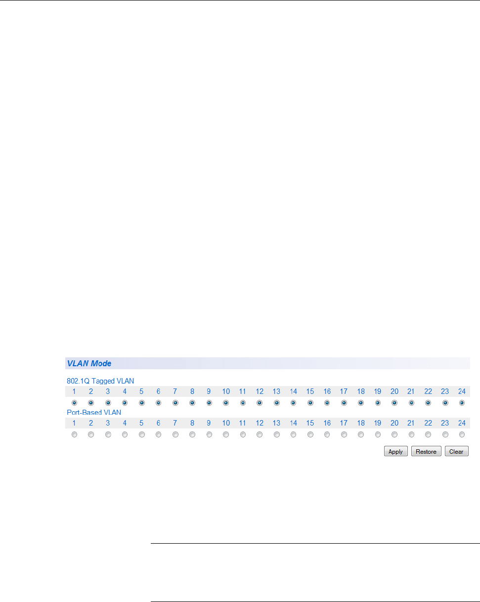
AT-GS950/24 Web Interface User Guide
81
Assign Ports to a VLAN Mode
The procedure described in this section allows you to assign ports to
tagged or a port-based VLAN. In addition, it permits you to display the
current VLAN assignment of ports.
However, you can assign ports to a port-based VLAN only after you have
created a port-based VLAN with the procedure described in “Port-Based
VLAN Configuration” on page 91.
By default, all of the ports on the switch are assigned as untagged
members to the default tagged VLAN with a VLAN ID of 1. The default
VLAN is permanent and must have at least one untagged port assigned to
it at any time.
To assign ports to a 802.1Q Tagged VLAN or Port-Based VLAN, perform
the following procedure:
1. From the main menu on the left side of the page, select Bridge.
The Bridge folder expands.
2. From the Bridge folder, select VLAN.
The VLAN folder expands.
3. From the VLAN folder, select VLAN Mode.
The VLAN Mode Page is displayed. See Figure 24.
Figure 24. AT-GS950/24 VLAN Mode Page
4. To add ports to a 802.1Q Tagged VLAN or Port-Based VLAN, select
the ports accordingly on the VLAN Mode page.
Note
Before you assign a port as a member of a Port-Base VLAN, you
must create the Port-Base VLAN by following the steps defined in
“Port-Based VLAN Configuration” on page 91

Chapter 5: Virtual LANs
82
5. Click Apply.
6. If you want to restore the port assignment before saving the
configuration, click Restore.
Note
Once the VLAN assignment has been saved by clicking first on the
Apply button and then saving the configuration, the Restore button
will not be active for those port assignments.
7. From the main menu on the left side of the page, select Save
Configuration to Flash to permanently save your changes.

AT-GS950/24 Web Interface User Guide
83
Tagged VLAN Configuration
On a port, the tag information within a frame is examined when it is
received to determine if the frame is qualified as a member of a specific
tagged VLAN. If it is, it is eligible to be switched to other member ports of
the same VLAN. If it is determined that the frame’s tag does not conform to
the tagged VLAN, the frame is discarded.
You can create and delete tagged VLANs by following the procedures in
the following sections:
“Create a Tagged VLAN”
“Modify a Tagged VLAN” on page 84
“Delete a Tagged VLAN” on page 87
Create a Tagged
VLAN
To create a tagged VLAN, perform the following procedure:
1. From the main menu on the left side of the page, select Bridge.
The Bridge folder expands.
2. From the Bridge folder, select VLAN.
The VLAN folder expands.
3. From the VLAN folder, select Tagged VLAN.
The AT-GS950/24 Tagged VLAN Page is displayed. See Figure 25.
Figure 25. AT-GS950/24 Tagged VLAN Page

Chapter 5: Virtual LANs
84
4. To assign a VLAN ID, type a VLAN ID in the VLAN ID field.
The range for this field is 2 to 4,000. You can create a maximum of 255
tagged VLANs.
5. To assign a name to the VLAN, type a unique name in the VLAN
Name field.
Enter a value of up to 32 characters. For more information about this
field, refer to “VLAN Name” on page 77.
6. Set the Management VLAN to one of the following choices from the
pull-down menu:
Enable - This parameter enables management access on this
VLAN.
Note
- If you enable management on a VLAN other than 1, you can
access management only through a tagged port of that VLAN.
- You can access management through the tagged port of all VLANs
on which you have enabled management.
- You can still access management through a port that is only an
untagged member of VLAN 1 and not a tagged member of another
VLAN.
Disable - This parameter disables Management VLAN on this
VLAN. If you change this parameter from Enable to Disable, the
Management VLAN is still enabled on the DefaultVLAN.
Note
The Management VLAN is always Enabled on the untagged ports of
the DefaultVLAN. It cannot be disabled on the DefaultVLAN.
7. To assign ports to the VLAN, click on the port numbers labeled either
Static Tagged or Static Untagged.
By default, all the ports are assigned to the Not Member category
when a specific VLAN is created. The Not Member ports are part of
the DefaultVLAN (VLAN ID=1).
8. Click Apply.
9. From the main menu on the left side of the page, select Save
Configuration to Flash to permanently save your changes.
Modify a Tagged
VLAN
To modify the name or port assignments of a tagged VLAN, perform the
following procedure:
1. From the main menu on the left side of the page, select Bridge.
The Bridge folder expands.
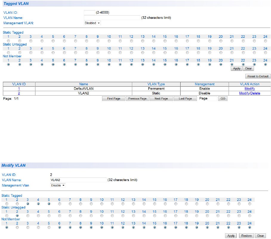
AT-GS950/24 Web Interface User Guide
85
2. From the Bridge folder, select VLAN.
The VLAN folder expands.
3. From the VLAN folder, select Tagged VLAN.
An example of a tagged VLAN (VLAN2) is shown in the table at the
bottom of Figure 26 on page 85.
Figure 26. Example of AT-GS950/24 Tagged VLAN Page
4. In the VLAN Action column, click Modify in the row of the VLAN that
you want to change.
The Modify VLAN Page is displayed, see Figure 27.
Figure 27. AT-GS950/24 Modify VLAN Page
5. You cannot modify the VLAN ID on this web page. If you want to delete
the VLAN ID, go to “Delete a Tagged VLAN” on page 87 for more
information.
Chapter 5: Virtual LANs
86
6. To change the VLAN Name, type a new VLAN Name in the VLAN
Name field.
For more information about this field, refer to “VLAN Name” on
page 77.

AT-GS950/24 Web Interface User Guide
87
7. To change the Management VLAN assignment, select one of the
following choices from the pull-down menu:
Enable - This parameter enables Management VLAN on this
VLAN. The Management VLAN will be disabled on all other
VLANs and only be operational on this VLAN.
Caution
If you Enable the Management VLAN on this VLAN and you are
connected to a Tagged Member port, you may loose your
connection to the AT-S109 Version 1.1.0 Management software.
Disable - This parameter disables Management VLAN on this
VLAN. If you change this parameter from Enable to Disable, the
Management VLAN will be enabled on the DefaultVLAN
automatically.
Note
The Management VLAN is always Enabled on the DefaultVLAN and
cannot be disabled.
8. To change the port selections, click on the port numbers labeled either
Static Tagged or Static Untagged.
9. Click Apply.
10. From the main menu on the left side of the page, select Save
Configuration to Flash to permanently save your changes.
Delete a Tagged
VLAN
To delete a tagged VLAN, perform the following procedure:
1. From the main menu on the left side of the page, select Bridge.
The Bridge folder expands.
2. From the Bridge folder, select VLAN.
The VLAN folder expands.
3. From the VLAN folder, select Tagged VLAN.
An example of the Tagged VLAN Page is shown in Figure 27 on page
85.
4. In the VLAN Action column, click delete next to the VLAN that you
want to delete.
A confirmation prompt is displayed.
5. Click OK to delete the VLAN or Cancel to cancel the deletion.

Chapter 5: Virtual LANs
88
Note
You cannot delete the Default VLAN which has a VID of 1.
6. From the main menu on the left side of the page, select Save
Configuration to Flash to permanently save your changes.

AT-GS950/24 Web Interface User Guide
89
Tagged VLAN Port Settings
To configure a VLAN port that is a member of a Tagged VLAN, perform
the following procedure:
1. From the main menu on the left side of the page, select Bridge.
The Bridge folder expands.
2. From the Bridge folder, select Port Settings.
The VLAN folder expands.
From the VLAN folder, select Port Settings.
A partial view of the AT-GS950/24 VLAN Port Settings is displayed. See
Figure 28.
Figure 28. AT-GS950/24 VLAN Port Setting Page
3. For a selected port, set the PVID field to an existing VLAN ID. For an
explanation of the PVID parameter, see the Port VLAN Identifier
section in “VLAN Overview” on page 76.
4. Set the Acceptable Frame Type to one of the following choices from
the pull-down menu:
All - This selection allows all incoming ingress frames presented to
the port to enter the switch.
Tagged - This selection allows only tagged frames presented to
the port to enter the switch. Untagged frames are discarded at
ingress.
Untagged and Priority Tagged - This selection allows only
untagged frames and frames with a priority tag that are presented
to the port to enter the switch. Tagged frames are discarded at
ingress.
5. From the Ingress Filtering parameter, select one of the following
choices from the pull-down menu:
Enable - This enables Ingress Filtering at the selected port.
Chapter 5: Virtual LANs
90
Disable - This disables Ingress Filtering at the selected port.
6. Click Apply.
The port configuration becomes effective.
7. If you need to configure other ports of the switch for the VLAN Port
Settings, repeat steps 4 through 7.
8. From the main menu on the left side of the page, select Save
Configuration to Flash to permanently save your changes.

AT-GS950/24 Web Interface User Guide
91
Port-Based VLAN Configuration
A port-based VLAN is a group of ports on the switch that form a logical
Ethernet segment. This type of VLAN is independent of the header
information including VLAN tags in a frame.
You can create and delete Port-Based VLANs by following the procedures
in the following sections:
“Create a Port-Based VLAN”
“Modify a Port-Based VLAN” on page 92
“Delete a Port-Based VLAN” on page 92
Create a Port-
Based VLAN
To create a port-based VLAN, perform the following procedure:
1. From the main menu on the left side of the page, select Bridge.
The Bridge folder expands.
2. From the Bridge folder, select VLAN.
The VLAN folder expands.
3. From the VLAN folder, select Port-Based VLAN.
The Port-Based VLAN Page is displayed. See Figure 29.
Figure 29. Port-Based VLAN Page
4. To assign a VLAN Index, type a VLAN ID in the VLAN Index field.
Choose a value between 1 and 64.
5. To assign a name to a VLAN, type a name in the VLAN Name field.
Enter a value of up to 32 characters. For more information about this
field, refer to “VLAN Name” on page 77.
6. To assign ports to the VLAN, click on the port numbers labeled Group
Member.

Chapter 5: Virtual LANs
92
7. Click Apply.
8. From the main menu on the left side of the page, select Save
Configuration to Flash to permanently save your changes.
Modify a Port-
Based VLAN
To modify the name or port assignments of a port-based VLAN, perform
the following procedure:
1. From the main menu on the left side of the page, select Bridge.
The Bridge folder expands.
2. From the Bridge folder, select VLAN.
The VLAN folder expands.
3. From the VLAN folder, select Port-Based VLAN.
The Port-Based VLAN Page is shown in Figure 29 on page 91.
4. In the VLAN Action column, click Modify next to the VLAN that you
want to change.
The Modify Port-based VLAN Page is displayed. See Figure 30.
Figure 30. AT-GS950/24 Modify Port-based VLAN
5. To change the name of the VLAN, type a new name in the VLAN
Name field.
Enter a value of up to 32 characters. For more information about this
field, refer to “VLAN Name” on page 77.
6. To assign ports to the VLAN, click on the port numbers labeled either
Group Member or Not Member.
7. Click Apply.
8. From the main menu on the left side of the page, select Save
Configuration to Flash to permanently save your changes.
Delete a Port-
Based VLAN
To delete a port-based VLAN, perform the following procedure:
1. From the main menu on the left side of the page, select Bridge.

AT-GS950/24 Web Interface User Guide
93
The Bridge folder expands.
2. From the Bridge folder, select VLAN.
The VLAN folder expands.
3. From the VLAN folder, select Port-Based VLAN.
The Port-Based VLAN Page is shown in Figure 29 on page 91.
4. In the VLAN Action column, click Delete next to the VLAN that you
want to delete.
A confirmation prompt is displayed.
5. Click OK to delete the VLAN or Cancel to cancel the deletion.
Note
You cannot delete the Default VLAN which has a VID of 1.
6. From the main menu on the left side of the page, select Save
Configuration to Flash to permanently save your changes.
Chapter 5: Virtual LANs
94


Chapter 6: GVRP
96
Overview and Guidelines
The GARP VLAN Registration Protocol (GVRP) allows network devices to
share VLAN information and to use the information to modify existing
VLANs or create new VLANs, automatically. This makes it easier to
manage VLANs that span more than one switch. Without GVRP, you have
to manually configure your switches to ensure that the various parts of the
VLANs can communicate with each other across the different switches.
With GVRP, which is an application of the Generic Attribute Registration
Protocol (GARP), this is done for you automatically.
Here are the guidelines for GVRP:
GVRP is supported with STP or RSTP or without spanning tree.
Both ports the constitute a network link between the switch and the
other device must be running GVRP.
You cannot modify or delete dynamic GVRP VLANs.
You cannot remove dynamic GVRP ports from static or dynamic
VLANs.
To be detected by GVRP, a VLAN must have at least one active
node or have at least one port with a valid link to an end node.
GVRP cannot detect a VLAN that does not have any active nodes
or valid port links.
Resetting the switch erases all dynamic GVRP VLANs and
dynamic GVRP port assignments. The dynamic assignments are
relearned by the switch as PDUs arrive on the ports from other
switches.
GVRP has three timers: join timer, leave timer, and leave all timer.
The values for these timers must be identically configured on all
switches running GVRP. Timers with different values on different
switches can result in GVRP compatibility problems.
You can convert dynamic GVRP VLANs and dynamic GVRP port
assignments to static VLANs and static port assignments.
The default port setting on the switch for GVRP is active, meaning
that the ports participate in GVRP. Allied Telesis recommends
disabling GVRP on those ports that are connected to GVRP-
inactive devices, meaning devices that do not feature GVRP.
PDUs are transmitted from only those switch ports where GVRP is
enabled.
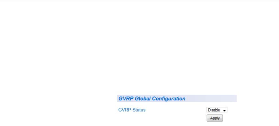
AT-GS950/24 Web Interface User Guide
97
General Configuration
Perform the following procedure to enable or disable GVRP:
1. From the main menu on the left side of the page, select Bridge.
The Bridge folder expands.
2. From the Bridge folder, select GVRP.
The GVRP folder expands.
3. From the GVRP folder, select GVRP Global Configuration.
The GVRP Global Configuration Page is displayed. See Figure 31.
Figure 31. GVRP Global Configuration Page
4. From the GVRP Status field, select one of the following choices from
the pull-down menu:
Enable - The GVRP feature is active.
Disable - The GVRP feature is inactive.
5. Click Apply.
The GVRP setting that you have selected is now active.
6. From the main menu on the left side of the page, select Save
Configuration to Flash to permanently save your changes.

Chapter 6: GVRP
98
Port Settings
Perform the following procedure to configure the GVRP port settings:
1. From the main menu on the left side of the page, select Bridge.
The Bridge folder expands.
2. From the Bridge folder, select GVRP.
The GVRP folder expands.
3. From the GVRP folder, select Port Settings.
A partial view of the AT-GS950/24 Port Settings Page is displayed.
See Figure 32.
Figure 32. AT-GS950/24 Port Settings Page
4. The following fields are listed for each port:
Port - This parameter displays the ports on the switch.
Dynamic Vlan Status - This parameter defines the GVRP status
of the port. From the Dynamic Vlan Status field, select one of the
following choices from the pull-down menu:
Ignore - This parameter indicates that the setting in the All row
does not apply to the Dynamic Vlan Status field. In other
words, each port is set individually.
Enable - The Dynamic Vlan is activated for the port row
selected.
Disable - The Dynamic Vlan is de-active for the port row
selected.
Restricted VLAN Registration - This parameter controls if the
VLAN registration on the port is restricted or not.
Ignore - This parameter indicates that the setting in the All row
does not apply to the Restricted VLAN Registration field. In
other words, each port is set individually.
Enable - The Restricted VLAN Registration is active for the
AT-GS950/24 Web Interface User Guide
99
port row selected.
Disable - The Restricted VLAN Registration is de-active for
the port row selected.
5. Once you have configured the parameters, click Apply for the affected
port.
6. If you want to configure GVRP for other ports, repeat steps 4 and 5.
7. From the main menu on the left side of the page, select Save
Configuration to Flash to permanently save your changes.

Chapter 6: GVRP
100
Time Settings
Perform the following procedure to configure the GVRP port settings:
1. From the main menu on the left side of the page, select Bridge.
The Bridge folder expands.
2. From the Bridge folder, select GVRP.
The GVRP folder expands.
3. From the GVRP folder, select GVRP Time Setting.
A partial view of the AT-GS950/24 GVRP Time Setting Page is
displayed. See Figure 33.
Figure 33. AT-GS950/24 GVRP Time Setting Page
GARPLeaveTimer must be greater than (GARPJoinTimer x2 + 10).
GARPLeaveAllTimer must be greater than (GARPLeaveTimer + 10).
The acceptable input values are multiples of 10. If you try to enter a
value that is not a multiple of 10, the value will be rounded down.
4. The following fields are listed for each port:
Port - This parameter displays the ports on the switch.
GarpJoinTime - This parameter is the GARP Join Timer. Its range
is 10 - 1073741810 milli-seconds.
GarpLeaveTime - This parameter is the GARP Leave Timer. Its
range is 30 - 2147483630 milli-seconds. This timer must be set in
relation to the GVRP Join Timer according to the following
equation:
GARPLeaveTimer >= (GARPJoinTimer X 2) + 10
GarpLeaveAllTime - This parameter is the GARP Leave Timer.Its
range si 30 - 2147483630 milli-seconds. This timer must be set in
relation to the GVRP Leave Timer according to the following

AT-GS950/24 Web Interface User Guide
101
equation:
GARPLeaveAllTimer > (GARPLeaveTimer + 10)
Note
To ensure compatibility between network devices, you need
to configure the same values for the GARP Join Timer, GARP Leave
Timer, and GARP Leave All Timer on all participating GVRP devices
in your network.
5. Once you have configured the parameters, click Apply for the affected
port.
6. If you want to configure the GVRP timers for other ports, repeat
steps 4 and 5.
7. From the main menu on the left side of the page, select Save
Configuration to Flash to permanently save your changes.
Chapter 6: GVRP
102

103
Chapter 7
Voice VLAN
This chapter contains a description of the AT-GS950/24 switch’s Voice
VLAN feature and the procedures to create, modify, and delete a voice
VLAN configuration. This chapter contains the following sections:
“Overview” on page 104
“General Guidelines” on page 107
“Configuration” on page 108
“OUI Setting” on page 111
Note
To permanently save your new settings or any changes to the
configuration file, select Save Configuration to Flash from the main
menu on the left side of the page.

Chapter 7: Voice VLAN
104
Overview
The AT-GS950/24 Voice VLAN feature is specifically designed to maintain
high quality, uninterrupted voice traffic through the switch. When talking on
a voice over IP phone, a user expects to have no interruptions in the
conversation and excellent voice quality. The Voice VLAN feature can be
configured to meet these requirements.
CoS with Voice
VLAN
The Voice VLAN CoS parameter maintains the voice quality between the
ingress and egress ports of the AT-GS950/24 switch. CoS must be
enabled for the Voice VLAN CoS priority to take effect. The CoS priority
level that you configure is applied to voice traffic on all ports of the voice
VLAN.
Normally, most (non-Voice) Ethernet traffic transverses the AT-GS950/24
switch through lower order egress queues. To avoid delays and
interruptions in the voice data flow, the CoS priority level assigned to the
voice VLAN should be mapped to a higher order queue and the
scheduling algorithm should be set to Strict Priority. These settings
ensure that the voice data packets are processed before other types of
data so that the voice quality is maintained as the voice data passes
through the AT-GS950/24 switch.
Note
For more information about how to configure these CoS parameters,
see “Mapping CoS Priorities to Egress Queues” on page 173 and
“Queue Scheduling Algorithm” on page 177.
Organization
Unique Identifier
(OUI)
Each IP phone manufacturer can be identified by one or more
Organization Unique Identifiers (OUIs). An OUI is three bytes long and is
usually expressed in hexadecimal format. It is imbedded into the first part
of each MAC address of an Ethernet network device. You can find the OUI
of an IP phone in the first three complete bytes of its MAC address.
Typically, you will find that all of the IP phones you are installing have the
same OUI in common.
The AT-GS950/24 switch identifies a voice data packet by comparing the
OUI information in the packet’s source MAC address with an OUI table
that you configure when you initially set up the voice VLAN. This is
important when the Auto-Detection feature for a port and is a dynamic
voice VLAN port.
Note
See “Dynamic Auto-Detection vs Static Ports” on page 105 for more
information about the Auto-Detection feature.

Chapter 7: Voice VLAN
106
One or more ports in your voice VLAN must be configured as Static
tagged or untagged members. Static VLAN members are permanent
member ports of the voice VLAN and there is no dependency on the
configuration of the devices connected to the ports. These ports might be
connected to other voice VLAN network nodes such as other Ethernet
switches, a telephone switch, and/or a DHCP server. The voice VLAN
Auto-Detection feature cannot be enabled on Static tagged or tagged
ports.
Note
Any Static tagged members of the voice VLAN are required to have
the port VLAN ID (PVID) configured to be the same as the voice
VLAN ID. This will insure that all untagged packets entering the port
are switched within the voice VLAN as the voice data passes
through the AT-GS950/24 switch.
If the IP phone(s) that you are installing cannot be configured with a VLAN
ID, then the switch ports should be configured as Static tagged ports
within the voice VLAN.
Note
Link Layer Discovery Protocol for Media Endpoint Devices
(LLDP- MED) is not supported on the AT-GS950/24 switch. Each IP
phone that is VLAN aware should be manually configured for the
VLAN ID that matches your AT-GS950/24 voice VLAN ID. Each of
the AT-GS950/24 voice VLAN ports connected to an IP phone
should be configured as “Not Member” ports of the tagged VLAN.
Note
Power over Ethernet (PoE) is not supported on the AT-GS950/24
switch.
Chapter 7: Voice VLAN
112
Modify OUI
Setting
To modify or delete an OUI, it must be first be deleted and then re-entered
by following the procedure in “Create OUI Setting” on page 111.
Delete OUI
Setting
To delete an OUI, perform the following procedure:
1. From the main menu on the left side of the page, select Bridge.
The Bridge folder expands.
2. From the Bridge folder, select Voice VLAN.
The Voice VLAN folder expands.
3. From the Voice VLAN folder, select Voice VLAN OUI Setting.
The Voice VLAN OUI Setting Page is displayed. See Figure 35 on
page 111.
4. To delete a specific OUI that had already been entered in the table at
the bottom of the page, click on Delete in the Action column of the
table. The specific OUI will be deleted from the table.
5. From the main menu on the left side of the page, select Save
Configuration to Flash to permanently save your changes.

113
Chapter 8
STP and RSTP
This chapter provides background information about the Spanning Tree
Protocol (STP) and the Rapid Spanning Tree Protocol (RSTP). In addition,
there are procedures to configure STP and RSTP. The sections in the
chapter include:
“Overview” on page 114
“Bridge Priority and the Root Bridge” on page 115
“Forwarding Delay and Topology Changes” on page 117
“Mixed STP and RSTP Networks” on page 119
“Spanning Tree and VLANs” on page 120
“Basic STP and RSTP Configuration” on page 123
“Configure RSTP Port Settings” on page 126
“Spanning Tree Topology” on page 131
For detailed information about STP, refer to IEEE Std 802.1D. For detailed
information about RSTP, refer to IEEE Std 802.1w.
Note
To permanently save your new settings or any changes to the
configuration file, select Save Configuration to Flash from the main
menu on the left side of the page.

AlliedWare Plus Version 2.1.2 Management Software Web Browser User’s Guide
123
Basic STP and RSTP Configuration
To configure the basic STP and RSTP settings, perform the following
procedure:
1. From the main menu on the left side of the page, select Bridge.
The Bridge folder expands.
2. From the Bridge folder, select the Spanning Tree folder.
The Spanning Tree folder expands.
3. From the Spanning Tree folder, select the RSTP folder.
The RSTP folder expands.
4. Form the RSTP folder, select RSTP.
The Rapid Spanning Tree Configuration Page is displayed. See Figure
40.
Figure 40. Rapid Spanning Tree Configuration Page

Chapter 8: STP and RSTP
124
The RSTP Configuration page allows you to configure basic STP
(STP-Compatible) or RSTP protocols as well as to view current
settings of the feature.
In the upper portion of the page, you can set the following
parameters:
Global RSTP Status - Set this field to activate or de-activate the
RSTP feature on the switch. From the Global RSTP Status field
at the top of the page, select one of the following choices from the
pull-down menu:
Enable - The RSTP feature is active. The other parameter fields
on the web page become active and are eligible for data to be
entered.
Disable - The RSTP feature is inactive. The other parameter
fields on the web page become inactive and are greyed out so
that data cannot be entered.
Protocol Version - Set this field to activate RSTP or STP on the
switch. To activate this field, select RSTP or STP-compatible and
then click Apply at the top of the page.
In the middle section of the page, the following fields are listed:
Note
You cannot change these fields.
Root Port - The active port on the switch that is communicating
with the root bridge. If the switch is the root bridge for the LAN,
then there is no root port and the root port parameter is set to 0.
Root Path Cost - The sum of all the root port costs of all the
bridges between the switch’s root port and the root bridge including
the switch’s root port cost.
Time Since Topology Change - The time in seconds since the
last topology change took place. When RSTP detects a change to
the LAN’s topology or when the switch is rebooted, this parameter
is reset to 0 seconds and begins incrementing until the next
topology change is detected.
Note
To update the Time Since Topology Change parameter, you must
refresh your browser.
Topology Change Count - An integer that reflects the number of
times RSTP has detected a topology change on the LAN since the
switch was initially powered on or rebooted.
AlliedWare Plus Version 2.1.2 Management Software Web Browser User’s Guide
125
The following parameters refer to the designated root bridge. You
cannot change these fields.
Designated Root - This parameter includes two fields: the root
bridge priority and the MAC address of the root bridge. For
example, 1000 00C08F1211BB shows the root bridge priority as
1000, and 00C08F1211BB as the MAC address.
Hello Time - This parameter is the Hello Me. See “Hello Time and
Bridge Protocol Data Units (BPDU)” on page 118. This parameter
affects only the root bridge.
Maximum Age - The parameter displays the maximum amount of
time that BPDU’s are stored before being deleted on the root
bridge.
Forward Delay - The parameter displays the time interval between
generating and sending configuration messages by the root bridge.
The bottom section of the web page provides information about the
bridge. The following parameters appear in the bottom third of the
web page:
Bridge ID - The Bridge ID is the MAC address of the bridge. The
bridge identifier is used as a tie breaker in the selection of the root
bridge when two or more bridges have the same bridge priority.
You cannot change this parameter.
Bridge Priority - The priority number for the bridge, in
hexadecimal format. This number is used to determine the root
bridge for RSTP. The bridge with the lowest priority number is
selected as the root bridge. If two or more bridges have the same
priority value, that is, the lowest value of all the other bridges, then
the bridge with the numerically lowest MAC address becomes the
root bridge. When a root bridge goes offline, the bridge with the
lowest priority number automatically takes over as the root bridge.
This parameter can be from 0X0000 to 0XF000, with 0XF000 being
the highest priority.
Bridge Hello Time - This is the time interval between generating
and sending configuration messages by the bridge. This parameter
is active only when the switch is the root bridge.
Bridge Maximum Age - The length of time after which stored
bridge protocol data units (BPDU’s) are deleted by the bridge.
Bridge Forward Delay - This is the time interval between
generating and sending configuration messages by the bridge.
5. Once you have configured the parameters, click Apply.
6. From the main menu on the left side of the page, select Save
Configuration to Flash to permanently save your changes.

Chapter 8: STP and RSTP
126
Configure RSTP Port Settings
This section contains the following topics:
“Configure the Basic RSTP Port Settings”
“Configure the Advanced RSTP Port Settings” on page 128
Configure the
Basic RSTP Port
Settings
To configure the basic RSTP port settings, perform the following
procedure:
1. From the main menu on the left side of the page, select Bridge.
The Bridge folder expands.
2. From the Bridge folder, select the Spanning Tree folder.
The Spanning Tree folder expands.
3. From the Spanning Tree folder, select the RSTP folder.
The RSTP folder expands.
4. From the RSTP folder, select the RSTP Basic Port.
A partial view of the AT-GS950/24 RSTP Basic Port Configuration
Page is displayed. See Figure 41.
Figure 41. AT-GS950/24 RSTP Basic Port Configuration Page
This page displays the following information about the ports:
Port - Indicates ports 1 through 24 on the AT-GS950/24 switch.
Use the All row to apply the same settings for the STP Status,
Priority, and Path Cost fields to your switch.
Trunk - Indicates the trunk assignment of a port.
Link Status - Indicates if the port link status is active (Up) or
inactive (Down).
Port State - Indicates one of the following port states:
Blocking - A blocking state does not allow network traffic to be
AlliedWare Plus Version 2.1.2 Management Software Web Browser User’s Guide
127
sent or received on a the port except for BPDU data. A port with
a higher path cost to the root bridge than another on the switch
will cause a switching loop and is placed in the blocking state by
the Spanning Tree algorithm. The port’s state may change to the
forwarding state if the other links in use fail and the Spanning
Tree algorithm determines the port may transition to the
forwarding state.
Listening - This state occurs on a port during the convergence
process. The port in the listening state processes BPDUs and
awaits new information that would cause the port to return to the
blocking state.
Learning - While the port does not yet forward frames (packets)
in this state, the port does learn source addresses from frames
received and adds them to the filtering (switching) database.
Forwarding - A port that both receives and sends data. This
indicates normal operation. STP continues to monitor the port
for incoming BPDUs that indicate the port should return to the
blocking state to prevent a loop.
Disabled - This state is not strictly part of STP. However, a
network administrator can manually disable a port.
Role - Indicates one of the following port roles:
Disabled - The Disabled Port role is assigned if the port is not
operational or is excluded from the active topology by
management or it is a network access port (IEEE Std 802.1X)
and it is Unauthorized, or its Administrative Bridge Port state is
Disabled.
Root - If the least cost path to the root is through this port, then it
becomes the root port for this bridge.
Designated - If this is the designated bridge for the LAN and if
the root path cost information received on this port is greater
than the root port's path cost and less than any other port's
received information, then this port becomes the designated
port.
Backup - Any operational Bridge Port that is not a Root or
Designated Port is a Backup Port if the Bridge is the Designated
Bridge for the attached LAN.
Alternate - Any operational Bridge Port that is not a Root or
a Designated Port is an Alternate Port if that Bridge is not the
Designated Bridge for the attached LAN.

133
Chapter 9
Multiple Spanning Tree Protocol
This chapter provides the procedures for configuring Multiple Spanning
Tree Protocol (MSTP). You can find an overview and configuration
guidelines for this feature in “MSTP Overview” on page 329.
When you configure MSTP, the information should be entered in order on
the following web pages:
“Multiple Spanning Tree Configuration” on page 134
“VLAN Mapping” on page 137
“Port Configuration” on page 139
“Port Settings” on page 142
“Topology Information” on page 144

Chapter 9: Multiple Spanning Tree Protocol
134
Multiple Spanning Tree Configuration
Head2 Head3
To configure the MSTP settings, perform the following procedure:
1. From the main menu on the left side of the page, select Bridge.
The Bridge folder expands.
2. From the Bridge folder, select the Spanning Tree folder.
The Spanning Tree folder expands.
3. From the Spanning Tree folder, select the MSTP folder.
The MSTP folder expands.
4. From the MSTP folder, select MSTP.
The Multiple Spanning Tree Configuration Page is displayed. See
Figure 44 on page 134.
Figure 44. Multiple Spanning Tree Configuration Page
The MSTP Configuration page allows you to configure the MSTP
parameters as well as to view current settings of the feature.
In the upper portion of the page, you can set the following
parameters:

AT-GS950/24 Web Interface User Guide
135
Global MSTP Status - Set this field to Enable or Disable the
MSTP feature on the switch. The Global MSTP Status must be set
to Enable before the other MSTP configuration parameters can be
set.
Note
Both RSTP and BPDU Passthrough must be disabled before you
enable MSTP.
Caution
Enabling or disabling MSTP causes the switch to temporarily stop
switching Ethernet network traffic.
Maximum MST Instances - This specifies the maximum number
of Multiple Spanning Tree Instances (MSTIs) that can be
configured. The range is 1 - 31.
Bridge Priority - This parameter specifies the priority used in
determining the regional root for a particular MSTI. For more
information about Bridge Priority, see Table 8 on page 340.
Region Name - This parameter specifies the region’s name where
the bridge is a member. This name must be identical to the
regional names specified on other switches in the same MSTP
region. See “Multiple Spanning Tree Regions” on page 338 for
more information.
Region Revision - The parameter indicates the region’s revision
and must be identical to the regional names specified on other
switches in the same MSTP region. See “Multiple Spanning Tree
Regions” on page 338 for more information.
Dynamic Path Cost Calculation - This parameter is either True or
False. When set to True, the path cost of each port on the bridge is
dynamically calculated based on the port speed. If the parameter is
set to False, the path cost of the bridge is based on the initial value
of the port speed.
In the middle section of the page, the status of the MSTP bridge
parameters are shown. The bottom section of the page is where
you can adjust the values of these parameters. The following fields
are listed:
Maximum Age - The Maximum Age defines the amount of time a
port will wait for STP/RSTP information. MSTP uses this parameter
when interacting with STP/RSTP domains on the boundary ports.
Its range is 6 - 40 seconds.
Forward Delay - The Forward Delay defines the time that the
Chapter 9: Multiple Spanning Tree Protocol
136
bridge spends in the listening and learning states. Its range is
4 - 30 seconds.
Maximum Hop Count - The Maximum Hop Count is a parameter
set in a BPDU packet when it originates. It is decremented by 1
each time it is retransmitted by the next bridge. When the Hop
Count value reaches zero, the bridge drops the BPDU packet. Its
range is 6 - 40 hops.
Transmit Hold Count - The Transmit Hold Count specifies the
maximum number of BPDUs that the bridge can send per second.
Its range is 1 - 10.
5. Once you have configured the parameters, click Apply.
6. From the main menu on the left side of the page, select Save
Configuration to Flash to permanently save your changes.
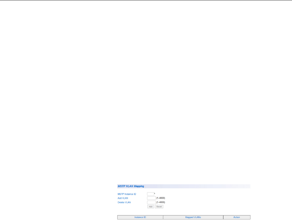
AT-GS950/24 Web Interface User Guide
137
VLAN Mapping
You can create, modify and delete MSTP settings with the procedures in
the following sections:
”Open MSTP VLAN Mapping Page”
”Create VLAN Mapping to MST Instance”.
“Modify MST Instance” on page 138.
“Delete MST Instance” on page 138.
Open MSTP
VLAN Mapping
Page
1. From the main menu on the left side of the page, select Bridge.
The Bridge folder expands.
2. From the Bridge folder, select the Spanning Tree folder.
The Spanning Tree folder expands.
3. From the Spanning Tree folder, select the MSTP folder.
The MSTP folder expands.
4. From the MSTP folder, select MSTP VLAN Mapping.
The MSTP VLAN Mapping Page is displayed. See Figure 45.
Figure 45. MSTP VLAN Mapping Page
Create VLAN
Mapping to MST
Instance
1. Enter the MSTP Instance ID. You can enter any number of MSTP IDs
up to the maximum MSTP ID. See “Multiple Spanning Tree
Configuration” on page 134 for more information.
2. Enter an existing VLAN ID in the ADD VLAN field that you want to
associate with the MSTI ID entered in step 4.
3. Click Add.
The Instance ID and the Mapped VLAN will be displayed in the table
on the page.
4. You may add as many VLANs to one MST Instance by repeating steps
4 through 6.
5. From the main menu on the left side of the page, select Save
Configuration to Flash to permanently save your changes.
Chapter 9: Multiple Spanning Tree Protocol
138
Modify MST
Instance
If you wish to modify a MST Instance, you must first delete the instance
and then redefine it. Refer to “Create VLAN Mapping to MST Instance” on
page 137 for more information.
Delete MST
Instance
1. In the Action column of the table, click on Delete for the MST Instance
that want to delete.
The instance is deleted along with the mapped associations to the
VLANs that are listed.
2. From the main menu on the left side of the page, select Save
Configuration to Flash to permanently save your changes.

AT-GS950/24 Web Interface User Guide
139
Port Configuration
To configure the MSTP parameters for each of the ports, perform the
following procedure:
1. From the main menu on the left side of the page, select Bridge.
The Bridge folder expands.
2. From the Bridge folder, select the Spanning Tree folder.
The Spanning Tree folder expands.
3. From the Spanning Tree folder, select the MSTP folder.
The MSTP folder expands.
4. From the MSTP folder, select MSTP Port Configuration.
A partial view of the AT-GS950/24 MSTP Port Configuration Page is
displayed. See Figure 46.
Figure 46. AT-GS950/24 MSTP Port Configuration Page
You may choose a port and configure its MSTP parameters on this
page. The following information is displayed:
Port - Indicates ports 1 through 24 on the AT-GS950/24 switch.
Use the All row to apply the same settings for the Point-to-Point
Status, Edge Port, MSTP Status, Protocol Migration, AutoEdge
Status, Restricted Role, Restricted TCN fields to all the ports on
your switch.
Path Cost - Specifies the cost of a port to the root.
Priority - Specifies the spanning tree port priority.
PointToPoint Status - Indicates if the port is connected to another
network device (point-to-point) in the network topology. See “Point-
to-Point and Edge Ports” on page 118 for more information.
ForcedTrue - The port is connected to a network device in the
Chapter 9: Multiple Spanning Tree Protocol
140
network topology.
ForcedFalse - The port is not connected to a network device in
the network topology.
Auto - The switch will automatically determine the port type.
Edge Port - Indicates if a port is connected to an edge device in
the network topology or not. See “Point-to-Point and Edge Ports”
on page 118 for more information.
True - The port is connected to an edge device and the port will
always be in a forwarding state.
False - The port is not connected to an edge device.
MSTP Status - Indicates if MSTP is Enabled or Disabled.
Enabled - MSTP is active on the port.
Disabled - MSTP is inactive on the port.
Protocol Migration - A switch running MSTP supports a built-in
protocol migration mechanism that enables it to inter-operate with
legacy 802.1D switches.
True - The switch is able to inter-operate with 802.1D BPDU
packets.
False - This switch can only operate with RSTP and MSTP
packets.
Hello Time - The Hello Time is frequency with which the root
bridge sends out a BPDU. See “Hello Time and Bridge Protocol
Data Units (BPDU)” on page 118 for more information.
AutoEdge Status - This parameter allows the switch to detect if
the port functioning as an edge port.
Restricted Role - This parameter prevents the port from becoming
a root port.
True - The port is prevented from being a root port or a port that
is used to communicate with the root bridge.
False - This switch can only operate with RSTP and MSTP
packets.
The net effect of setting all ports on the switch to True is that it
forces the switch into the role of the root bridge regardless of other
path costs in the network.
Restricted TCN - The Restricted TCN parameter does not allow
Topology Change Notification (TCN) BPDUs to be processed on
the port.
AT-GS950/24 Web Interface User Guide
143
6. If you choose to change the MSTP port settings for other ports, repeat
steps 4 and 5.
7. From the main menu on the left side of the page, select Save
Configuration to Flash to permanently save your changes.

Chapter 9: Multiple Spanning Tree Protocol
144
Topology Information
To configure the MSTP port settings, perform the following procedure:
1. From the main menu on the left side of the page, select Bridge.
The Bridge folder expands.
2. From the Bridge folder, select the Spanning Tree folder.
The Spanning Tree folder expands.
3. From the Spanning Tree folder, select the MSTP folder.
The MSTP folder expands.
4. From the MSTP folder, select MSTP Port Settings.
A partial view of the AT-GS950/24 Topology Information Page is
displayed. See Figure 48.
Figure 48. AT-GS950/24 Topology Information Page
The following information displayed on this page shows the current
status of MSTP for each port:
Port - Indicates ports 1 through 24 on the AT-GS950/24 switch.
Designated Root - The designated root bridge to which the
switch’s root port is actively connected.
Root Priority - This parameter specifies the priority used in
determining the regional root for a particular MSTI. For more
information, see Table 8 on page 340.
Designated Bridge - The bridge providing the least cost path to
the root bridge from a network segment.
Designated Port - The port providing the least cost path to the
root bridge from a network segment.
Designated Cost - The cost from the designated bridge to the root
bridge.
Regional Root - The root bridge of the MST instance.
Chapter 9: Multiple Spanning Tree Protocol
146

147
Chapter 10
Static Port Trunking
This chapter contains a description of port trunking and the procedures for
creating, modifying, and deleting a static port trunk. The following topics
are discussed:
“Overview” on page 148
“Create a Port Trunk” on page 151
“Modify a Port Trunk” on page 153
“Disable a Port Trunk” on page 155
Note
For information about Link Aggregation Control Protocol (LACP) port
trunking, see Chapter 11, “LACP Port Trunks” on page 157.
Note
To permanently save your new settings or any changes to the
configuration file, select Save Configuration to Flash from the main
menu on the left side of the page.

AT-GS950/24 Web Interface User Guide
149
Network equipment vendors tend to employ different techniques to
implement static trunks. Consequently, a static trunk on one device may
be incompatible with the same feature on a device from a different
manufacturer. For this reason static trunks are typically employed only
between devices from the same vendor. That is not to say that an Allied
Telesis Layer 2 managed switch cannot form a static trunk with a device
from another manufacturer; however, the implementations of static
trunking on the two devices may be incompatible.
Also, note that a static trunk does not provide for redundancy or link
backup. If a port in a static trunk loses its link, the trunk’s total bandwidth is
diminished. Although the traffic carried by the lost link is shifted to one of
the remaining ports in the trunk, the bandwidth remains reduced until the
lost link is re-established or you reconfigure the trunk by adding another
port to it.
General Guidelines
Following are the guidelines for creating a static trunk:
Allied Telesis recommends setting static port trunks between Allied
Telesis networking devices to ensure compatibility.
A static trunk can contain up to eight ports.
The ports of a static trunk must be of the same medium type. They
can be all twisted-pair ports or all fiber optic ports, but not a
combination of the two.
The ports of a trunk can be either consecutive (for example, Ports
2 through 4) or nonconsecutive (for example, ports 3, 5, and 7).
Before creating a port trunk, verify that the settings are the same
for all ports in the trunk including speed (1000/Full), duplex mode,
flow control, back pressure settings and VLAN membership. If
these settings are not the same, then the switch does not allow you
to create the trunk.
Note
When a trunk group is formed with only combo ports as members, all
port members are configured to the forced port mode at 1000/Full.
The trunk ports on the connecting network switch should also be
configured for 1000/Full to insure speed and duplex compatibility
between the switches.
After you have created a port trunk, a change to the speed, duplex
mode, flow control, or back pressure of any port in the trunk
automatically implements the same change on all the other
member ports.
A port can belong to only one static trunk at a time.
The ports of a static trunk can be configured to be members of
Chapter 10: Static Port Trunking
154
9. Configure the port trunk on the other switch with the same parameters.
10. Connect the Ethernet cables between trunk ports on the AT-GS950/24
switch and the trunk ports on the other switch.

AT-GS950/24 Web Interface User Guide
155
Disable a Port Trunk
This procedure explains how to disable a port trunk.
Caution
Before you disable or modify a port trunk, disconnect all of the
cables from the ports of the trunk. Leaving the cables connected
during the reconfiguration of a trunk can create loops in your
network topology. Loops can result in broadcast storms which can
severely limited the effective bandwidth of your network.
To disable a port trunk, perform the following procedure:
1. Disconnect all of the Ethernet cables from the ports of the trunk.
2. Select the Bridge folder.
The Bridge folder expands.
3. From the Bridge folder, select the Trunk Config folder.
The Trunk Config folder expands.
4. From the Trunk Config folder, select Trunking.
The Trunking Page is shown in Figure 50 on page 151.
5. To disable a port trunk, select Disable from the pull-down menu next
to the trunk that you want to disable.
6. Click Apply.
7. From the main menu on the left side of the page, select Save
Configuration to Flash to permanently save your changes.
8. Modify the port trunk configuration in the same way on the other
switch.

AT-GS950/24 Web Interface User Guide
157
Chapter 11
LACP Port Trunks
This chapter contains overview information about LACP port trunks and
the procedures for setting this feature. This chapter contains the following
sections:
“System Priority” on page 159
“Port Priority Value” on page 159
“General Guidelines” on page 161
“Group Status” on page 163
“Port Priority Configuration” on page 166
Note
For information about port trunking, see Chapter 10, “Static Port
Trunking” on page 147.
Note
To permanently save your new settings or any changes to the
configuration file, select Save Configuration to Flash from the
main menu on the left side of the page.

AT-GS950/24 Web Interface User Guide
159
System Priority
It is possible for two devices interconnected by an aggregate trunk to
encounter a conflict when they form the trunk. For example, the two
devices might not support the same number of active ports in an
aggregate trunk or might not agree on which ports are active and which
are in standby mode.
If a conflict does occur, the two devices need a mechanism for resolving
the problem and deciding whose LACP settings take precedence. This is
the function of the system LACP priority value. This value is used
whenever the devices encounter a conflict creating a trunk - the lower the
number, the higher the priority. As a result, the settings on the device with
the higher priority take precedence over the settings on the other device. If
both devices have the same system LACP priority value, the settings on
the switch with the lowest MAC address take precedence. In the AT-S109
Version 1.1.0 Management software, the MAC address is called the
System ID.
The LACP System Priority is pre-assigned and you cannot alter this
parameter.
Port Priority Value
The switch uses a port’s LACP priority to determine which ports are active
and which are in the standby mode in situations where the number of ports
in the aggregate trunk exceeds the highest allowed number of active ports.
This parameter is a value in a range of 1 to 255, based on the port
number. For instance, the priority values for ports 2 and 11 are 002 and
011, respectively. The lower the number, the higher the priority. Ports with
the highest priorities are designated as the active ports in an aggregate
trunk.
For example, if both 802.3ad-compliant devices support up to six active
ports and there are a total of eight ports in the trunk, the six ports with the
highest priorities (lowest priority values) are designated as the active
ports, and the others are placed in the standby mode. If an active link goes
down on a active port, the standby port with the next highest priority is
automatically activated to take its place.
The selection of the active links in an aggregate trunk is dynamic and
changes as links are added, removed, lost, or reestablished. For example,
if an active port loses its link and is replaced by another port in the standby
mode, the re-establishment of the link on the originally active port causes
the port to return to the active state by virtue of having a higher priority
value than the replacement port, which returns to the standby mode.

AT-GS950/24 Web Interface User Guide
165
Figure 53. LACP Group Status Page with Three Cables Connected
You can now see that each port has been grouped under a single
aggregator since the ports are now in a Link-Up status.

Chapter 11: LACP Port Trunks
166
Port Priority Configuration
To select a priority for an LACP port, perform the following procedure:
1. Select the Bridge folder.
The Bridge folder expands.
2. From the Bridge folder, select the Trunk Config folder.
The Trunk Config folder expands.
3. From the Trunk Config folder, select Port Priority.
A partial view of the AT-GS950/24 Port Priority Page is displayed. See
Figure 54.
Figure 54. AT-GS950/24 Port Priority Page
The System Priority is a preassigned value that you cannot alter. This
value applies to the switch. See “System Priority” on page 159.
The System ID is a MAC address value assigned to the switch. You
cannot change this value.
4. To set the port priority, select a value from 0 to 255 in the Priority
column for the port you want to alter. For more information, see “Port
Priority Value” on page 159
5. Select Apply.
6. From the main menu on the left side of the page, select Save
Configuration to Flash to permanently save your changes.

AT-GS950/24 Web Interface User Guide
173
Mapping CoS Priorities to Egress Queues
Before mapping the CoS priorities and the egress queues, you must
disable the Jumbo frame parameter on each port. See the Jumbo
parameter definition in “Display and Configure Ports” on page 63.
Note
When Jumbo frames are enabled, COS can not be enabled.
To configure CoS mapping, perform the following procedure:
1. From the main menu on the left side of the page, select Bridge.
The Bridge folder expands.
2. From the Bridge folder, select QoS.
The QoS folder expands.
3. From the QoS folder, select CoS.
The CoS Page is displayed. See Figure 55.
Figure 55. CoS Page
Chapter 12: Quality of Service (CoS)
174
4. For each Traffic Class whose queue you want to change, click on the
Queue (0, 1, 2, or 3) radio button that applies to your configuration.
5. After you have completed this mapping process, select Enable in the
QoS Status field,
6. Click Apply.
7. From the main menu on the left side of the page, select Save
Configuration to Flash to permanently save your changes.

AT-GS950/24 Web Interface User Guide
175
Associate Ports to CoS Priorities
The Port Priority values is assigned to an untagged frame at ingress for
internal processing in the switch. This procedure explains how to change
the default mappings of port priorities to the User Priority. This is set at the
switch level. You cannot set this at the per-port level.
To change the port priority mappings, perform the following procedure.
1. From the main menu on the left side of the page, select Bridge.
The Bridge folder expands.
2. From the Bridge folder, select QoS.
The QoS folder expands.
3. From the QoS folder, select Port Priority.
A partial view of the AT-GS950/24 Port Priority Page page is shown in
Figure 56.
Figure 56. AT-GS950/24 Port Priority Page
4. For each port whose priority you want to change, select a priority (0-7)
in the User Priority column.
5. Click Apply for each port.
6. From the main menu on the left side of the page, select Save
Configuration to Flash to permanently save your changes.

Chapter 12: Quality of Service (CoS)
176
Associate DSCP Classes to Egress Queues
If you choose to use the DSCP tags in your Access Control policy
configuration, each DSCP value (0-63) that is relevant to
your configuration needs to be mapped to one of the four egress queues
(0-3). The default queue for all DSCP values is 0.To assign the queue
mappings to the DSCP values, perform the following procedure.
1. From the main menu on the left side of the page, select Bridge.
The Bridge folder expands.
2. From the Bridge folder, select QoS.
The QoS folder expands.
3. From the QoS folder, select DSCP.
The DSCP Class Mapping Page page is shown in Figure 57.
Figure 57. DSCP Class Mapping Page
4. For each DSCP In value that is relevant to your configuration, select a
queue (0-3) in the Queue column.
5. After you have completed this mapping process, click Apply.
6. From the main menu on the left side of the page, select Save
Configuration to Flash to permanently save your changes.
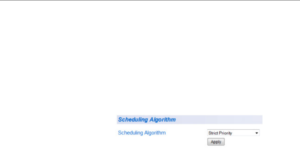
AT-GS950/24 Web Interface User Guide
177
Queue Scheduling Algorithm
To change the scheduling algorithm for the egress queues, perform the
following procedure.
1. From the main menu on the left side of the page, select Bridge.
The Bridge folder expands.
2. From the Bridge folder, select QoS.
The QoS folder expands.
3. From the QoS folder, select Scheduling Algorithm.
The Scheduling Algorithm Page page is shown in Figure 58.
Figure 58. Scheduling Algorithm Page
4. In the Scheduling Algorithm list, select the algorithm, one of the
following:
Strict Priority - The port transmits all packets out of higher priority
queues before transmitting any from the lower priority queues.
WRR (Weighted RoundRobin) - The port transmits a set number
of packets from each queue, in a round robin fashion, so that each
has a chance to transmit traffic. See Table 5 on page 172 for
number of packets versus the port egress queue.
5. Click Apply.
6. From the main menu on the left side of the page, select Save
Configuration to Flash to permanently save your changes.
Chapter 12: Quality of Service (CoS)
178

179
Chapter 13
Access Control Configuration
Access Control configuration allows you to control different aspects of the
Ethernet traffic as it enters the switch ports and is process through the
switch. You can specify what traffic is permitted or denied to flow through
the switch by setting up specific filter criteria at an ingress port. You can
also manage the switching priority of ethernet packets. All of this is done
by specifying policies that define the filtering and priority behavior.
Note
Before you specify the Access Control policies, be sure to configure
the QoS parameters. The QoS entries may have a direct affect on
each policy’s behavior. For more information, see Chapter 12,
“Quality of Service (CoS)” on page 167.
Before a policy can be defined, you need to specify certain ACL
configuration information. This information must be entered sequentially
on the following web pages:
“Classifier” on page 180
“Profile Action” on page 185
“In-Profile Action” on page 189
“Out-Profile Action” on page 193
“Port List” on page 197
With the unique index number from each of these web pages, you can
configure a “Policy” on page 200
If you define multiple policies for different ports, you can go to “Policy
Sequence” on page 205 to display the order that policies are applied to
each port.

Chapter 13: Access Control Configuration
180
Classifier
The Create Classifier page allows you to specify packet settings for
filtering Ethernet traffic.
You can create, modify or delete a Classifier by following the procedures
in the following sections:
“Create Classifier,” next
“Modify Classifier” on page 182
“Delete Classifier” on page 183
Create Classifier To create a classifier, perform the following procedure:
1. From the main menu on the left side of the page, select the Access
Control Config folder.
The Access Control Config folder expands.
2. From the Access Control Config folder, select Classifier.
The Create Classifier page is displayed in Figure 59.
Figure 59. Create Classifier Page
Chapter 13: Access Control Configuration
188
4. Click on the OK button.
The profile action entry is deleted from the profile action table.
5. From the main menu on the left side of the page, select Save
Configuration to Flash to permanently save your changes.

AT-GS950/24 Web Interface User Guide
189
In-Profile Action
The Create In-Profile Action page allows you to specify a Profile Action’s
Permit or Deny privilege for packets in the ingress queue.
Note
A Profile Action Index is required to create an In-Profile Action.
See “Create Profile Action” on page 185 for more information.
You can create, modify or delete an In-Profile Action by following the
procedures in the following sections:
“Create In-Profile Action,” next
“Modify In-Profile Action” on page 191
“Delete In-Profile Action” on page 192
Create In-Profile
Action
To create an in-profile action, perform the following procedure:
1. From the main menu on the left side of the page, select the Access
Control Config folder.
The Access Control Config folder expands.
2. From the Access Control Config folder, select In-Profile Action.
The Create In-Profile Action page is displayed in Figure 65.
Figure 65. Create In-Profile Action Page
3. Enter a number in the In-Profile Action Index field. The Index must be
a unique number within the range of 1 - 65535. This field is mandatory.
Note
The In-Profile Action Index is a required parameter when you create
a Policy. See “Create Policy” on page 200 for more information.

Chapter 13: Access Control Configuration
190
4. Enter a number in the Profile Action ID field ranging from 0 to 72.
This field is mandatory.
Note
This field must be pre-defined on the Create Profile page - see
“Create Profile Action” on page 185 for more information.
5. In the Deny/Permit field, use the pull down menu to select one of the
following parameters:
Deny - This selection drops ingress packets that conform to the
specified Profile Action ID.
Permit - This selection allows ingress packets that conform to the
specified Profile Action ID to be processed by the switch.
Note
You must enter a selection for Deny/Permit field even if the Profile
Action ID that you have entered ignores both the Policed-DSCP and
Policed-CoS fields.
6. Click Add.
The In-Profile Action entry is added to the status table. If you do not
see you new entry, you may need to navigate to another page of the
table with the First Page, Previous Page, Next Page, and Last Page
buttons located below the table. An example of a In-Profile Action table
entry is displayed in Figure 66.
Figure 66. Example of In-Profile Action Entry
7. From the main menu on the left side of the page, select Save
Configuration to Flash to permanently save your changes.

AT-GS950/24 Web Interface User Guide
191
Modify In-Profile
Action
To modify a In-Profile action entry, perform the following procedure:
Note
You must first enter a In-Profile action before you can modify it. See
“Create In-Profile Action” on page 189 for more information.
1. From the main menu on the left side of the page, select the Access
Control Config folder.
The Access Control Config folder expands.
2. From the Access Control Config folder, select In-Profile Action.
An example of the Create In-Profile Action page with a In-Profile Action
table entry is shown in Figure 66 on page 190.
3. Select the table entry that you want to modify and click the modify link
in the Action column.
The Modify In-Profile Action page will be displayed. See Figure 67 on
page 191.
Figure 67. Modify In-Profile Action Page
4. Change the parameters as required.
Note
See “Create In-Profile Action” on page 189 for the definitions of each
parameters.
5. Click Apply.
The modified In-Profile action entry is displayed in the table at the
bottom of the page of the Create In-Profile Action page.
6. From the main menu on the left side of the page, select Save
Configuration to Flash to permanently save your changes.
Chapter 13: Access Control Configuration
192
Delete In-Profile
Action
To delete a In-Profile action entry, perform the following procedure:
1. From the main menu on the left side of the page, select the Access
Control Config folder.
The Access Control Config folder expands.
2. From the Access Control Config folder, select In-Profile Action.
An example of the Create In-Profile Action page with a In-Profile
Action table entry is shown in Figure 66.
3. From the Create In-Profile Action page, identify which In-Profile action
table entry that want to delete and click the Delete button in the Action
column.
You will be prompted with a message saying, “Do you want to delete
In-Profile Action xx?” (where xx is the classifier index).
4. Click on the OK button.
The In-Profile action entry is deleted from the In-Profile action table.
5. From the main menu on the left side of the page, select Save
Configuration to Flash to permanently save your changes.
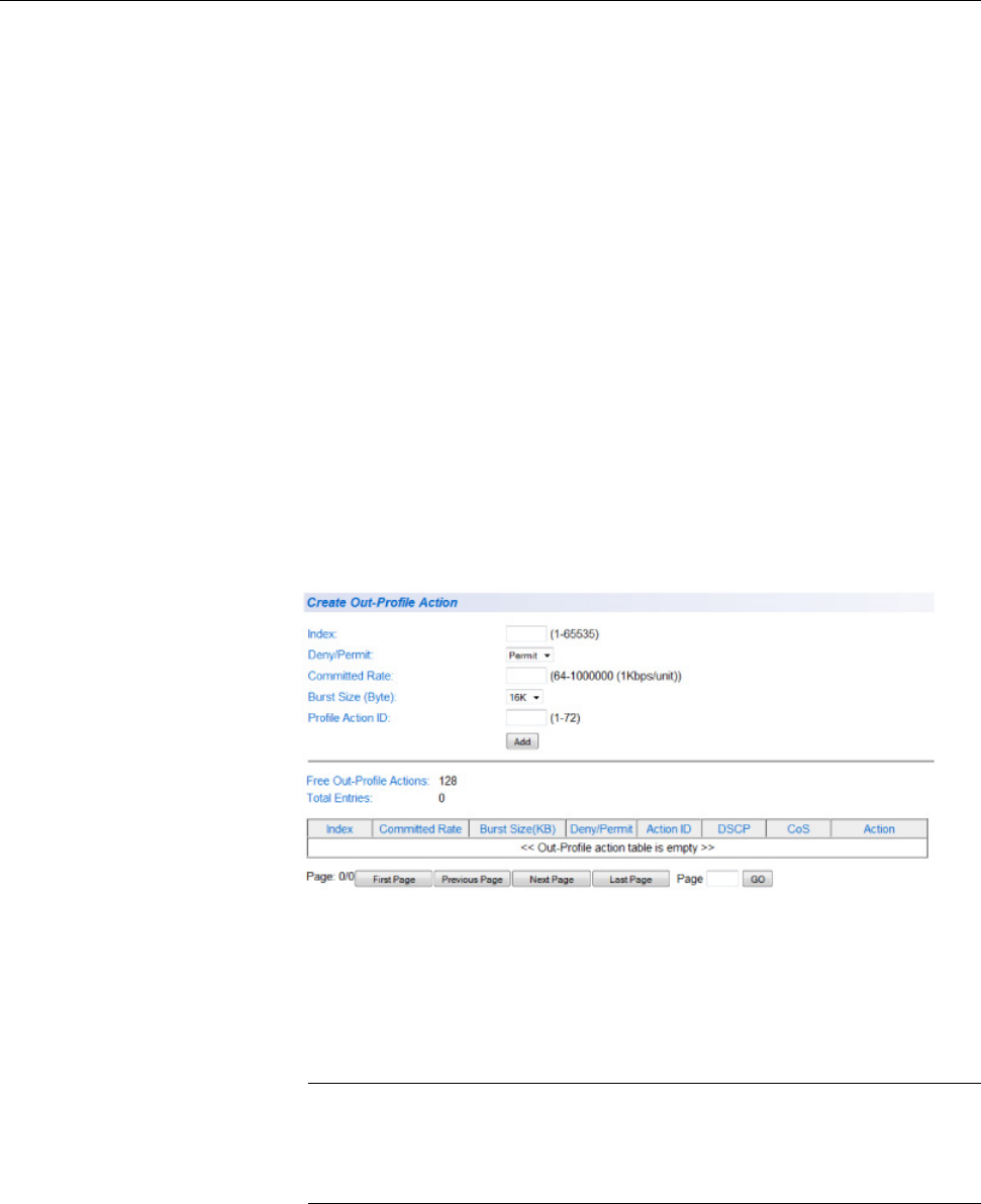
AT-GS950/24 Web Interface User Guide
193
Out-Profile Action
The Create Out-Profile Action page allows you to specify a Profile Action’s
Permit or Deny privilege and bandwidth restrictions for packets in the
egress queue.
You can create, modify or delete an Out-Profile Action by following the
procedures in the following sections:
“Create Out-Profile Action,” next
“Modify Out-Profile Action” on page 195
“Delete In-Profile Action” on page 192
Create Out-
Profile Action
To create a Out-Profile Action, perform the following procedure:
1. From the main menu on the left side of the page, select the Access
Control Config folder.
The Access Control Config folder expands.
2. From the Access Control Config folder, select Out-Profile Action.
The Create Out-Profile Action page is displayed in Figure 68.
Figure 68. Create Out-Profile Action Page
3. Enter a number in the Out-Profile Action Index field.
The Index must be a unique number within the range of 1 - 65535. This
field is mandatory.
Note
The Out-Profile Action Index is a required parameter when you
create a Policy. See “Create Policy” on page 200 for more
information.

Chapter 13: Access Control Configuration
194
4. Enter a number in the Profile Action ID field ranging from 0 to 72.
This field is mandatory.
Note
This field must be pre-defined on the Create Profile page - see
“Create Profile Action” on page 185 for more information.
5. In the Deny/Permit field, use the pull down menu to select one of the
following parameters:
Deny - This selection drops ingress packets that conform to the
specified Profile Action ID.
Permit - This selection allows ingress packets that conform to the
specified Profile Action ID to be processed by the switch.
Note
You must enter a selection for Deny/Permit field even if the Profile
Action ID that you have entered ignores both the Policed-DSCP and
Policed-CoS fields.
6. Click Add.
The Out-Profile Action entry is added to the status table. If the Page
field located below the table displays a page number and you do not
see your new entry, then there are multiple pages of the table that you
can navigate. This is done by clicking on the First Page, Previous
Page, Next Page, and Last Page buttons located below the table. An
example of a Out-Profile Action table entry is displayed in Figure 69.
Figure 69. Example of Out-Profile Action Entry
7. From the main menu on the left side of the page, select Save
Configuration to Flash to permanently save your changes.
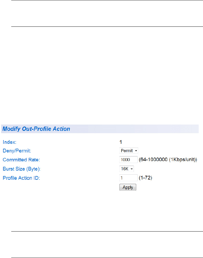
AT-GS950/24 Web Interface User Guide
195
Modify Out-
Profile Action
To modify a Out-Profile action entry, perform the following procedure:
Note
Before you can modify an entry, you must first enter a Out-Profile
action - see “Create In-Profile Action” on page 189.
1. From the main menu on the left side of the page, select the Access
Control Config folder.
The Access Control Config folder expands.
2. From the Access Control Config folder, select Out-Profile Action.
An example of the Create Out-Profile Action page with a Out-Profile
Action table entry is shown in Figure 69 on page 194.
3. Select the table entry that you want to modify and click the modify link
in the Action column.
The Modify Out-Profile Action page will be displayed. See Figure 70.
Figure 70. Modify Out-Profile Action Page
4. Change the parameters as required.
Note
See “Create In-Profile Action” on page 189 for the definitions of each
parameters.
5. Click Apply.
The modified Out-Profile action entry is displayed in the table at the
bottom of the page of the Create Out-Profile Action page.
6. From the main menu on the left side of the page, select Save
Configuration to Flash to permanently save your changes.
Chapter 13: Access Control Configuration
196
Delete Out-
Profile Action
To delete a Out-Profile action entry, perform the following procedure:
1. From the main menu on the left side of the page, select the Access
Control Config folder.
The Access Control Config folder expands.
2. From the Access Control Config folder, select Out-Profile Action.
An example of the Create Out-Profile Action page with a Out-Profile
Action table entry is shown in Figure 69 on page 194.
3. From the Create Out-Profile Action page, identify which Out-Profile
action table entry that want to delete and click the Delete button in the
Action column.
You will be prompted with a message saying, “Do you want to delete
Out-Profile Action xx?” (where xx is the classifier index).
4. Click on the OK button.
The Out-Profile action entry is deleted from the Out-Profile action
table.
5. From the main menu on the left side of the page, select Save
Configuration to Flash to permanently save your changes.

AT-GS950/24 Web Interface User Guide
199
Figure 73. Modify Port List Page
4. Change the parameters as required.
Note
See “Create Port List” on page 197 for the definitions of each
parameters.
5. Click Apply.
The modified Port List entry is displayed in the table at the bottom of
the page of the Create Port List page.
6. From the main menu on the left side of the page, select Save
Configuration to Flash to permanently save your changes.
Delete Port List To delete a Port List entry, perform the following procedure:
1. From the main menu on the left side of the page, select the Access
Control Config folder.
The Access Control Config folder expands.
2. From the Access Control Config folder, select Port List.
An example of the Create Port List page with a Port List table entry is
shown in Figure 72 on page 198.
3. From the Create Port List page, identify which Port List table entry that
want to delete and click the Delete button in the Action column.
You will be prompted with a message saying, “Do you want to delete
Port List xxxxx?” (where xxxxx is the classifier index).
4. Click on the OK button.
The Port List entry is deleted from the Port List table.
5. From the main menu on the left side of the page, select Save
Configuration to Flash to permanently save your changes.
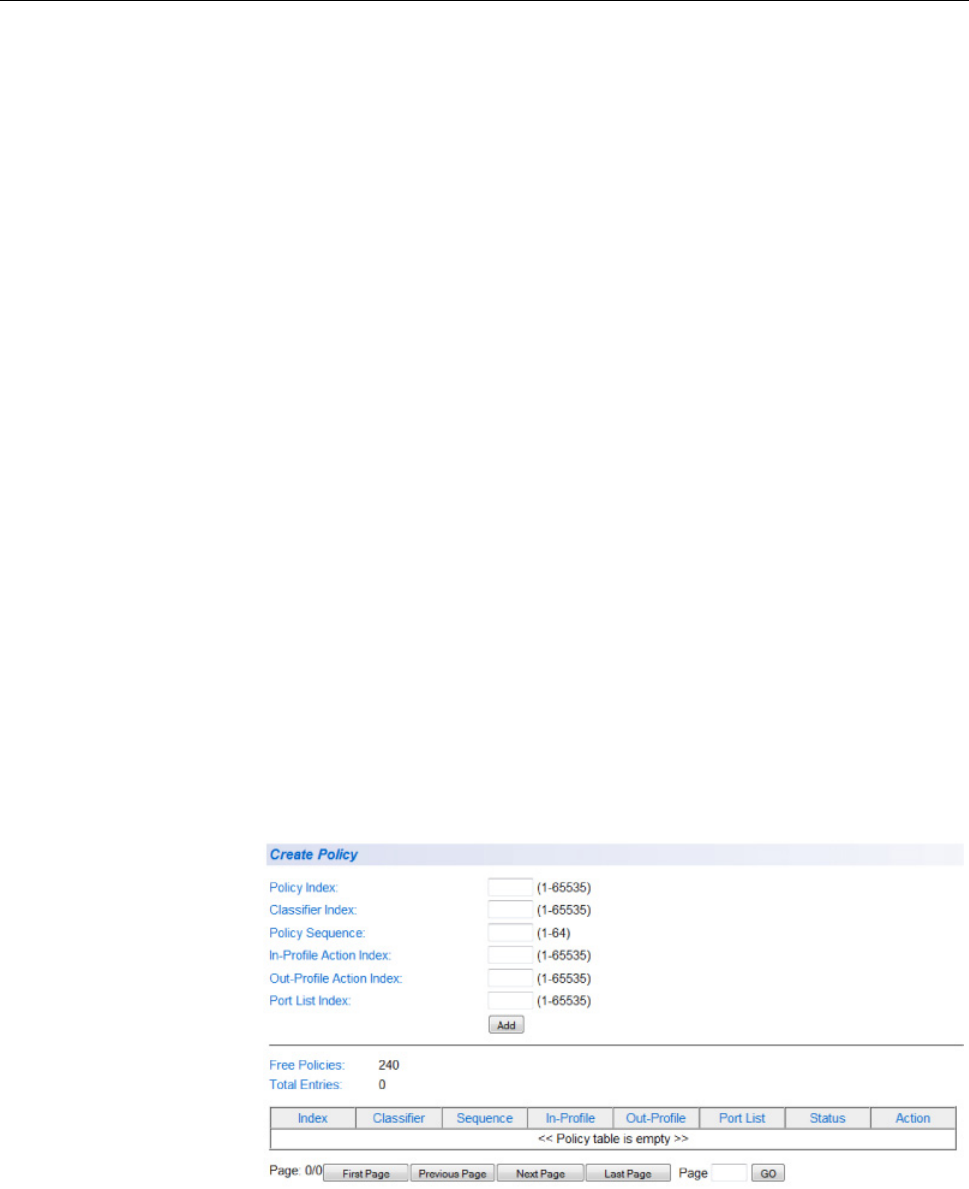
Chapter 13: Access Control Configuration
200
Policy
The Create Policy page allows you to specify the filtering criteria for one
policy. Before creating a policy, you must pre-define the following indexes:
Classifier Index - See “Create Classifier” on page 180 for more
information.
In-Profile Action Index - See “Create In-Profile Action” on
page 189 for more information.
Out-Profile Action Index - See “Create Out-Profile Action” on
page 193 for more information.
Port List Index - See “Create Port List” on page 197 for more
information.
You can create, modify or delete a Policy by following the procedures in
the following sections:
“Create Policy,” next
“Modify Policy” on page 202
“Delete Policy” on page 203
Create Policy To create an Policy, perform the following procedure:
1. From the main menu on the left side of the page, select the Access
Control Config folder.
The Access Control Config folder expands.
2. From the Access Control Config folder, select Policy.
The Create Policy page is displayed in Figure 74.
Figure 74. Create Policy Page
AT-GS950/24 Web Interface User Guide
201
3. Enter a number in the Policy Index field.
The Policy Index is a unique number within the range of 1 - 65535
which identifies the policy. This field is mandatory.
4. Enter data in the remaining parameters. All parameters listed below
must be entered to form the policy:
Classifier Index - The Classifier Index is a unique number within
the range of 1 - 65535. This field is mandatory and must match
a Classifier Index that you previously entered on the Create
Classifier page. See the Classifier table described in
“Create Classifier” on page 180 for more information.
Policy Sequence - The Policy Sequence field is a unique number
within the range of 1 - 64. It identifies the when a specific policy is
executed relative to the other policies. This field is mandatory. See
for more information
In-Profile Action Index - The In-Profile Action Index is a unique
number within the range of 1 - 65535. This field is mandatory and
must match a In-Profile Action Index that has been previously
entered on the Create In-Profile Action page. See the In-Profile
Action table described in “Create In-Profile Action” on page 189 for
more information.
Out-Profile Action Index - The Out-Profile Action Index is a
unique number within the range of 1 - 65535. This field is
mandatory and must match a Out-Profile Action Index that has
been previously entered on the Out-Profile Action page. See the
Out-Profile Action table in “Create Out-Profile Action” on page 193
for more information.
Port List Index - The Port List Index is a unique number within the
range of 1 - 65535. This field is mandatory and must match a Port
List Index that has been previously entered on the Create Port List
page. See the Port List table “Create Port List” on page 197 for
more information.
5. Click Add.
The Policy entry is added to the status table. If you do not see you new
entry, you may need to navigate to another page of the table with the
First Page, Previous Page, Next Page, and Last Page buttons
located below the table. An example of a Policy table entry is displayed
in Figure 75 on page 202.
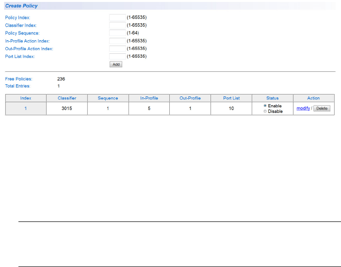
Chapter 13: Access Control Configuration
202
Figure 75. Example of Policy Entry
6. From the main menu on the left side of the page, select Save
Configuration to Flash to permanently save your changes.
Modify Policy To modify a Policy entry, perform the following procedure:
Note
Before you can modify an entry, you must first enter a Policy - see
“Create Policy” on page 200.
1. From the main menu on the left side of the page, select the Access
Control Config folder.
The Access Control Config folder expands.
2. From the Access Control Config folder, select Policy.
An example of the Create Policy page with a Policy table entry is
shown in Figure 75.
3. Select the table entry that you want to modify and click the modify link
in the Action column.
The Modify Policy page will be displayed. See Figure 76 on page 203.
Chapter 13: Access Control Configuration
204
2. From the Access Control Config folder, select Policy.
An example of the Create Policy page with a Policy table entry is
shown in Figure 75 on page 202.
3. From the Create Policy page, identify which Policy table entry that
want to delete and click the Delete button in the Action column.
You will be prompted with a message saying, “Do you want to delete
Policy xxxxx?” (where xxxxx is the classifier index).
4. Click on the OK button.
The Policy entry is deleted from the Policy table.
5. From the main menu on the left side of the page, select Save
Configuration to Flash to permanently save your changes.
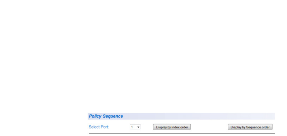
AT-GS950/24 Web Interface User Guide
205
Policy Sequence
The Policy Sequence page displays the order that policies are applied to
each port. You can order the display by Policy Index or by Policy
Sequence number.
To display the policy sequence, perform the following procedure:
1. From the main menu on the left side of the page, select the Access
Control Config folder.
The Access Control Config folder expands.
2. From the Access Control Config folder, select Policy Sequence.
The Policy Sequence page is displayed in Figure 77.
Figure 77. Policy Sequence Page
3. Select the switch port from the Select Port pull down menu that you
want to view.
4. Click either the Display by Index order or Display by Sequence
order button to view the Policy Sequence.
Chapter 13: Access Control Configuration
206

207
Chapter 14
Storm Control
This chapter contains a description and configuration procedures for the
Storm Control (bandwidth) feature. The following topics are discussed:
“Overview” on page 208
“Configuration” on page 210
“Ingress Rate Limiting” on page 212
“Egress Rate Limiting” on page 214
Note
To permanently save your new settings or any changes to the
configuration file, select Save Configuration to Flash from the main
menu on the left side of the page.
AT-GS950/24 Web Interface User Guide
209
Ingress Rate
Limiting
The Ingress Rate Limiting feature restricts the traffic to a pre-configured
data rate that can flow into a port. This data rate limit can be configured in
64 Kbps increments within a range from 64 Kbps to 1000 Mbps. The
formula for calculating the bandwidth limit is as follows:
Bandwidth = 64Kbps x rate limit
The rate limit parameter is an integer ranging from 1 to 15625.
Egress Rate
Limiting
The Egress Rate Limiting feature restricts the traffic to a pre-configured
data rate that can flow out of a port. This data rate limit can be configured
in 64 Kbps increments within a range from 64 Kbps to 1000 Mbps. The
formula for calculating the bandwidth limit for the 10/100/1000Base-T ports
is as follows:
Bandwidth = 64Kbps x rate limit
The rate limit parameter is an integer ranging from 1 to 15625.

Chapter 14: Storm Control
210
Configuration
This procedure explains how to set DLF, broadcast, multicast, and
threshold levels for each port on the AT-GS950/24 switch.
To change the settings of the storm control feature, perform the following
procedure:
1. From the main menu on the left side of the page, select the Bridge
folder.
2. From the Bridge folder, select Bandwidth Control.
The Bandwidth Control folder expands.
3. From the Bandwidth Control folder, select Storm Control.
A partial view of the AT-GS950/24 Storm Control page is displayed.
See Figure 78.
Figure 78. AT-GS950/24 Storm Control Page
4. To enable or disable the DLF field, select Enable or Disable from the
DLF pull-down menu next to the port that you want to change.
You can select the ALL row to set all of the ports to the same setting.
Note
For more information about the Destination Lookup Failure (DLF)
setting, see “Overview” on page 208.
5. Click Apply.
6. To enable or disable ingress and egress Broadcast packets, select
Enable or Disable from the Broadcast pull-down menu next to the
port that you want to change.
You can select the ALL row to set all of the ports to the same setting.

AT-GS950/24 Web Interface User Guide
211
Note
For more information, see the Broadcast setting definition
in“Overview” on page 208.
7. Click Apply.
8. To enable or disable ingress and egress Multicast packets, select
Enable or Disable from the Multicast pull-down menu next to the port
that you want to change.
You can select the ALL row to set all of the ports to the same setting.
Note
For more information, see the Multicast setting definition in
“Overview” on page 208.
9. Click Apply.
10. To set the Threshold field, use the pull-down menu next to the port
that you want to change. Select Low, Medium, or High which
correspond to the following values:
Low - Specifies 450 to 550 packets per second.
Medium - Specifies 880 to 1,000 packets per second.
High - Specifies 2,200 to 2,500 packets per second.
11. You can select the ALL row to set all of the ports to the same setting.
Note
For more information, see the Threshold setting definition in
“Overview” on page 208.
12. Click Apply.
13. From the main menu on the left side of the page, select Save
Configuration to Flash to permanently save your changes.
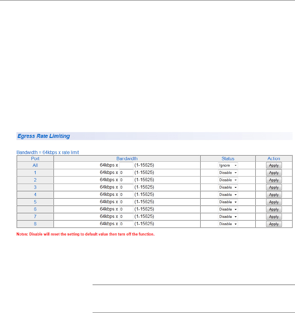
Chapter 14: Storm Control
212
Ingress Rate Limiting
This procedure explains how to set Bandwidth levels and Status for
Ingress Rate Limiting on each port of the AT-GS950/24 switch.
To change the settings of the ingress rate limiting feature, perform the
following procedure:
1. From the main menu on the left side of the page, select the Bridge
folder
2. From the Bridge folder, select Bandwidth Control.
The Bandwidth Control folder expands.
3. From the Bandwidth Control folder, select Ingress Rate Filtering.
A partial view of the AT-GS950/24 Ingress Rate Limiting page is
displayed. See Figure 79.
.
Figure 79. AT-GS950/24 Ingress Rate Limiting Page
4. To set the Bandwidth field on the AT-GS950/24 switch, enter a
number in the range of 1 - 15625.
Note
See “Ingress Rate Limiting” on page 209 for calculating the
bandwidth limit set by the Bandwidth field.
You can select the ALL row to set all of the ports to the same setting.
5. To enable or disable ingress rate filter, select Enable or Disable from
the Status pull-down menu next to the port that you want to change.
You can select the ALL row to set all of the ports to the same setting.
6. Click Apply.

215
Chapter 15
MAC Address Table
This chapter contains a description of the static multicast MAC address
feature and the procedure for configuring it. This chapter includes the
following sections:
“Overview” on page 216
“Static Unicast MAC Address Configuration” on page 218
“Static Multicast Address Configuration” on page 222
“Modify Static Multicast Address” on page 224
“Delete Static Multicast Address” on page 225
Note
To permanently save your new settings or any changes to the
configuration file, select Save Configuration to Flash from the main
menu on the left side of the page.

Chapter 15: MAC Address Table
216
Overview
The AT-GS950/24 switch has a MAC address table with a storage
capacity of up to 8,000 entries. The table stores the MAC addresses of the
network nodes connected to its ports and the port number where each
address is learned.
There are two types of MAC addresses - dynamic and static.
Dynamic MAC addresses are addresses that the switch learns
automatically by examining the source MAC addresses of the frames
received by the ports. This type of MAC address is not stored indefinitely
in the MAC address table. The switch deletes a dynamic MAC address
from the table if it does not receive any frames from the node after a
specified period of time. The switch assumes that the node is no longer
active and that its MAC address can be purged from the table. This
prevents the MAC address table from becoming filled with addresses of
nodes that are no longer active.
The MAC address table can also store a static MAC address which is a
MAC address of an end node that you assign to a switch port manually. A
static MAC address remains in the table indefinitely and is never deleted
by the switch, even when the end node is inactive. You can only delete a
static MAC address by manually configuring the switch with the AT-S109
Version 1.1.0 Management software.
There are two reasons to enter static MAC addresses. You may want to
enter end nodes the switch does not learn in its normal dynamic learning
process. Or, you want a MAC address to remain permanently in the table,
even when the end node is inactive.
Static multicast addresses are a subset of the static MAC addresses. With
the Static Multicast Address feature, you can add static multicast
addresses to the MAC address table. You can then assign the static
MAC address to a port or ports which are called Group Members in the
AT-S109 Version 1.1.0 interface. Each port has a maximum limit of 256
static multicast addresses.
In some network environments that are confined to one LAN (such as an
industrial application with a server, a switch and many controllers), there
may be various multicast streams that need to be distributed to some
network nodes, but not others. If the data sent in these streams is time-
sensitive and cannot be delayed because of the configuration time
associated with the IGMP Snooping feature, then static multicast
addresses may be the solution.
If a multicast address and its associated ports of the switch are predefined
within the network design and they will not change over time, then they
can be manually entered as static entries into the MAC address table. This
AT-GS950/24 Web Interface User Guide
217
allows the multicast stream to be forwarded immediately to those
predefined ports entered in the MAC table without any configuration
delays or loss of data.

Chapter 15: MAC Address Table
222
Static Multicast Address Configuration
This procedure explains how to set the static multicast feature for each
port on the AT-GS950/24 switch.
To add a static MAC address to the switch, perform the following
procedure:
1. From the main menu on the left side of the page, select the Bridge
folder.
The Bridge folder expands.
2. From the Bridge folder, select Static Multicast.
The Static Multicast Address Table Page is displayed. See Figure 82.
Figure 82. AT-GS950/24 Static Multicast Address Table Page
Before continuing, you must create an 802.1Q VLAN ID(s) or a Port-
Based VLAN Index(s). For information about defining these
parameters, go to:
“Tagged VLAN Configuration” on page 83 regarding the 802.1Q
VLAN ID parameter.
“Port-Based VLAN Configuration” on page 91 regarding the Port-
Based VLAN Index parameter.
3. Select either the 802.1Q VLAN ID or Port-Based VLAN Index radio
button and enter the respective VLAN ID (1-4000) or VLAN Index (1 -
52).
Note
An error message is generated when you enter a VLAN ID or VLAN
Index which is not been defined or when you enter a
VLAN ID or VLAN Index without also clicking on the respective
radio button.

AT-GS950/24 Web Interface User Guide
223
4. In the Group MAC Address field, enter a multicast MAC address.
The range is from 01:00:5E:00:01:00 to 01:00:5E:7F:FF:FF.
5. Assign the MAC address a Group Member (or members) by selecting
the check box beside each port number.
Note
You can assign a maximum limit of 256 static multicast addresses
on the switch.
6. Click Add.
The Static Multicast Address Table is updated with the new MAC
Address.
Note
The Group MAC Address values that you enter on the Static
Multicast Address Table Page are also displayed on the IGMP
Snooping Page. For more information, see “IGMP Snooping
Configuration” on page 242.
7. From the main menu on the left side of the page, select Save
Configuration to Flash to permanently save your changes.

Chapter 15: MAC Address Table
224
Modify Static Multicast Address
To modify the port assignment of a multicast MAC address in the MAC
address table, perform the following procedure:
1. From the main menu on the left side of the page, select the Bridge
folder.
2. From the Bridge folder, select Static Multicast.
The Static Multicast Address Table Page is displayed. See Figure 82
on page 222.
3. Select Modify next to the static MAC address that you want to change.
The Modify Static Multicast Address Page is displayed (not shown).
4. In the Group Member row, select the check boxes for the ports that
you want to include or remove in the Group Member area.
5. Selected ports are indicated with a check mark.
Note
To restore the original group member ports, click Restore.
6. Click Apply.
7. From the main menu on the left side of the page, select Save
Configuration to Flash to permanently save your changes.

AT-GS950/24 Web Interface User Guide
225
Delete Static Multicast Address
To delete a multicast MAC address from the MAC address table, perform
the following procedure:
1. From the main menu on the left side of the page, select the Bridge
folder.
1. From the Bridge folder, select Static Multicast.
The Static Multicast Address Table Page is displayed. See Figure 82
on page 222.
2. Select delete next to the static multicast address that you want to
remove.
The static multicast address is removed from the Static Multicast
Address Table Page.
3. From the main menu on the left side of the page, select Save
Configuration to Flash to permanently save your changes.
Chapter 15: MAC Address Table
226

227
Chapter 16
DHCP Snooping
This chapter contains a description of the AT-GS950/24 switch’s DHCP
Snooping feature and the procedures for creating, modifying, and deleting
the DHCP Snooping configuration. This chapter contains the following
sections:
“Overview” on page 228
“Trusted Ports” on page 228
“Untrusted Ports” on page 228
“Unauthorized DHCP Servers” on page 228
“DHCP with Option 82” on page 229
“General Guidelines” on page 230
“General Configuration” on page 231
“VLAN Setting” on page 233
“Trusted and Untrusted Port Configuration” on page 235
“Binding Database” on page 236
Note
To permanently save your new settings or any changes to the
configuration file, select Save Configuration to Flash from the main
menu on the left side of the page.
AT-GS950/24 Web Interface User Guide
229
first DHCPOFFER packet from the server that it receives. This packet
contains the DHCP server’s IP address and mask. If the unauthorized
DHCP server responds first, then the network device will use the
information from the unintended DHCP server for the default gateway or
DNS server.
Untrusted ports are connected to the DHCP clients and to traffic that
originated outside the LAN. By definition, untrusted ports do not accept
DHCP packets originating form a DHCP server and immediately drop
them when they are detected. The DHCP packets types that are not
accepted are DHCPOFFER and DHCPACK.
However, untrusted ports do accept both DHCP DISCOVER and
DHCPREQUEST packets sent from DHCP clients. This behavior
allows DHCP clients to respond to a trusted DHCP server and not respond
to a DHCP server that is untrusted.
DHCP with
Option 82
You can configure the AT-GS950/24 to pass DHCP packets containing
Option 82 information through the switch without altering the information
within the packet. You can also configure the AT-GS950/24 switch to
insert DHCP Option 82 information directly into the DHCP packets as they
pass through the switch.

AT-GS950/24 Web Interface User Guide
235
Trusted and Untrusted Port Configuration
The following procedure describes how to configure the DHCP Snooping
trusted interfaces on the AT-GS950/24 switch:
1. From the main menu on the left side of the page, select DHCP
Snooping.
The DHCP Snooping folder expands.
2. From the DHCP Snooping folder, select Trusted Interfaces.
A partial view of the AT-GS950/24 Trusted Interfaces page is
displayed. See Figure 85.
Figure 85. AT-GS950/24 Trusted Interfaces Page
3. From the Trust column, select one of the following choices from the
pull-down menu:
Disable - This parameter defines the port as untrusted for the
DHCP Snooping feature.
Enable - This parameter defines the port as trusted for the DHCP
Snooping feature.
4. Click Apply for the port.
The port is now configured for you selection.
5. If you choose to configure other switch ports as trusted or untrusted,
repeat steps 3 and 4.
6. From the main menu on the left side of the page, select Save
Configuration to Flash to permanently save your changes.

Chapter 16: DHCP Snooping
236
Binding Database
The Binding Database displays learned and statically assigned MAC
Address and IP Address information for each host on the local area
network. Dynamically assigned IP addresses from the DHCP server will
automatically populate the table on the Binding Database page as they
are assigned by the server. Statically assigned IP addresses are entered
manually by entering the host’s address information and clicking on the
Add button.
The following procedure describes how to configure the DHCP Snooping
Binding Database on the AT-GS950/24 switch for static IP addresses and
how to view the MAC Address and IP Address information for all of the
hosts on your local area network:
1. From the main menu on the left side of the page, select DHCP
Snooping.
The DHCP Snooping folder expands.
2. From the DHCP Snooping folder, select Binding Database.
A partial view of the AT-GS950/24 Binding Database page is
displayed. See Figure 86.
Figure 86. AT-GS950/24 Binding Database Page
Static IP
Addresses
To enter a statically assigned IP address for a host, perform the following
procedure:
1. Enter the host information into the following fields:
MAC Address - Enter the host’s MAC Address.
IP Address - Enter the static IP Address assigned to the host.
VLAN - Enter the host’s VLAN ID.
Port - Enter the port number where the host is connected.
AT-GS950/24 Web Interface User Guide
237
Type - Because the IP Address being entered is static, you must
select Static.
Lease Time - Enter the time that IP address assignment is valid. The
range is 10 to 4294967295 seconds.
2. Click Add.
The static address information is entered into the Binding Database.
Viewing Dynamically assigned IP address from the DHCP server will automatically
populate the table on the Binding Database page. You must enter
statically assigned IP Addresses and their corresponding fields at the top
of the web page. See “Static IP Addresses” on page 236 for more
information.
The Binding Database table at the bottom of the web page displays the
following information:
MAC Address - This parameter shows the host’s MAC Address.
VLAN ID - This parameter shows the host’s VLAN ID of which the
DHCP client is a member.
IP Address - This parameter is the IP Address assigned by the
DHCP server to the DHCP client.
Port - This parameter is the port number where the DHCP client is
connected.
Type - This parameter indicates the following:
Learned - The host IP Address is dynamically assigned by the
DHCP server.
Static - The host IP Address is statically assigned. See “Static
IP Addresses” on page 236 for more information.
Lease Time - This parameter is the time that IP address
assignment by the DHCP server is valid.
3. If the Page field located below the table displays a page number, then
there are multiple pages of the table that you can navigate. This is
done by clicking on the First Page, Previous Page, Next Page, and
Last Page buttons located below the table.
Chapter 16: DHCP Snooping
238

239
Chapter 17
IGMP Snooping
This chapter contains a description of the IGMP Snooping procedure as
well as procedures for working with IGMP Snooping in the web interface.
The following topics are discussed:
“Overview” on page 240
“IGMP Snooping Configuration” on page 242
Note
To permanently save your new settings or any changes to the
configuration file, select Save Configuration to Flash from the main
menu on the left side of the page.

AT-GS950/24 Web Interface User Guide
247
Port Access
Control
Configuration
To configure port-based access control, perform the following procedure:
1. Select the Security folder from the main menu on the left side of the
page.
The Security folder expands.
2. From the Security folder, select Port Access Control. The Port
Access Control Configuration Page is displayed. See Figure 89.
Figure 89. Port Access Control Configuration Page
3. Configure the following parameters as required:
NAS ID - This parameter assigns an 802.1x identifier to the switch
that applies to all ports. The NAS ID can be up to sixteen
characters. Valid characters are 0 to 9, a to z, and A to Z. Spaces
are allowed. Specifying an NAS ID is optional.
Port Access Control - This parameter enables or disables Port
Access Control. Select one of the following choices from the pull-
down menu:
Enable - The Port Access Control feature is activated.
Disable - The Port Access Control feature is de-activated.
Authentication Method - This parameter indicates the
authentication method used by the switch. Select one of the
following choices:
RADIUS - This parameter configures port security for remote
authentication. After completing steps 4 - 6, you must configure
the “RADIUS Client” on page 251.
Local - This parameter configures port security for local
authentication.After completing steps 4 - 6, you must configure
the parameters for “Dial-in User - Local Authentication” on
page 254.
When you are finished configuring the parameters, click Apply.
4. Click Settings to configure advanced configuration parameters.
Configure the following parameters as required:
AT-GS950/24 Web Interface User Guide
249
Supplicant Mode - This parameter specifies if one or more
supplicants can be authenticated on a port.
Single - The port is set to permit only one supplicant to log on
and forwards only the traffic of that supplicant. After one
supplicant has logged on, the port discards packets from any
other supplicant.
Multiple - The port is set to permit multiple clients on an
authenticator port. An authenticator mode forwards packets from
all clients once one client has successfully logged on.
Piggyback Mode - This mode is used in conjunction with the
Multiple Supplicant Mode. This mode is typically used in situations
where you want to add 802.1x port-based network access control
to a switch port that is supporting multiple clients, but do not want
to create individual accounts for all the clients on the RADIUS
server. After one client has successfully logged, the port permits
the other clients to piggy-back onto the initial client’s log on, so that
they can forward packets through the port without being
authentication.
Enabled - The Piggyback Mode is Enabled.
Disabled - The Piggyback Mode is Disabled.
VLAN Assignment - This parameter allows:
Enabled - The VLAN Assignment is Enabled.
Disabled - The VLAN Assignment is Disabled.
Secure VLAN - This field is inactive
Guest VLAN ID - This parameter specifies the VLAN ID that is
designated as a Guest VLAN. The range is 0 to 4000 where 0 is
disabled.
When a supplicant account is created on the RADIUS server, a
VLAN identifier must be entered along with a username and
password combination or MAC address information. If the switch
receives a valid VLAN ID or VLAN name from the RADIUS server,
it moves the authenticator port to the designated Guest VLAN and
changes the port to the authorized state.
Transmission Period - Sets the switch-to-client retransmission
time for EAPrequest frames. The range is 1 to 65535 seconds.
Quiet Period - Sets the number of seconds that authenticator
ports wait after a failed authentication before accepting
authentication requests again. The range is 1 to 65535 seconds.
Supplicant Timeout - Sets the switch-to-client retransmission time
for EAPrequest frames. The range is 1 to 65535 seconds.
Chapter 18: Security
250
Maximum Request - Specifies the maximum number of times
authenticator ports transmit EAP Request packets to clients before
timing out authentication sessions. The range is 1 to 10.
Re-authentication Period - Specifies the time interval for
reauthentication of clients on an authenticator port. The range is 1
to 65535 seconds
Server Timeout - Sets the length of time the switch waits for a
response from the authentication server. The range is 1 to 65535
seconds.
5. From the main menu on the left side of the page, select Save
Configuration to Flash to permanently save your changes.

Chapter 18: Security
252
You need to specify the user name and password combinations when
configuring the RADIUS server software on the authentication server.
Note
This manual does not explain how to configure RADIUS server
software. Refer to the documentation that comes with the RADIUS
server software for instructions.
You must activate the RADIUS client software on the switch using the
AT-S109 Version 1.1.0 Management software and configure the
settings. This is explained in “Port Access Control Configuration” on
page 247 and “Radius Client Configuration”.
For more information about the RADIUS authentication protocol, refer
to the RFC 2865 standard.
Radius Client
Configuration
To configure the RADIUS client, perform the following procedure:
1. From the main menu on the left side of the page, select the Security
folder.
The Security folder expands.
2. From the Security folder, select RADIUS.
The RADIUS Page is displayed. See Figure 90.
Figure 90. RADIUS Page
3. To enter the RADIUS server’s IP address, enter the address in the
Server IP Address field in the format xxx.xxx.xxx.xxx.
4. Type the port number in the Server Port field that you want to assign
to UDP.
You may only assign one port number to this parameter.
5. Type the port number in the Accounting Port field that you want to
assign to UDP.
You may only assign one port number to this parameter.
6. To specify the server’s encryption key, enter the encryption key in the
Shared Secret field.
AT-GS950/24 Web Interface User Guide
253
7. Click Apply to save your changes.
8. From the main menu on the left side of the page, select Save
Configuration to Flash to permanently save your changes.

Chapter 18: Security
254
Dial-in User - Local Authentication
Dial-in User feature provides the local authentication server for port
security when a remote (RADIUS) server is not available. This section
includes the following:
“Overview” on page 254
“Dial-in User Configuration” on page 254
Note
To permanently save your new settings or any changes to the
configuration file, select Save Configuration to Flash from the
main menu on the left side of the page.
Overview The Dial-in User (local) authentication method allows you to set up 802.1x
authentication parameters internally in the switch. In this case, the user
name and password combinations are entered with an optional VLAN
when they are defined. Based on these entries, the authentication process
of a supplicant is done locally by the AT-S109 Version 1.1.0 Management
software using a standard EAPOL (EAP over LAN) transaction.
Dial-in User
Configuration
The procedures in this section describe how to create, delete, and modify
dial-in users. See the following procedures:
“Add a Dial-in User” on page 254
“Modify a Dial-in User” on page 255
“Delete a Dial-in User” on page 256
Add a Dial-in User
To set up a user’s dial-in access, perform the following procedure:
1. From the main menu on the left side of the page, select the Security
folder.
The Security folder expands.
2. From the Security folder, select Dial-in User.
The Dial-in User page is displayed. See Figure 91 on page 255.
Produkt Specifikationer
| Mærke: | Candy |
| Kategori: | Ovn |
| Model: | fp 319 x |
Har du brug for hjælp?
Hvis du har brug for hjælp til Candy fp 319 x stil et spørgsmål nedenfor, og andre brugere vil svare dig
Ovn Candy Manualer

28 Marts 2025
5 Februar 2025
15 Januar 2025
15 Januar 2025
14 Januar 2025
10 Januar 2025
10 Januar 2025
9 Januar 2025
22 December 2024
22 December 2024
Ovn Manualer
- Ovn DeLonghi
- Ovn Sinbo
- Ovn Ikea
- Ovn Bosch
- Ovn SilverCrest
- Ovn PKM
- Ovn Gram
- Ovn Sencor
- Ovn Krups
- Ovn Maxxmee
- Ovn Wolkenstein
- Ovn Siemens
- Ovn Day
- Ovn Samsung
- Ovn Scandomestic
- Ovn GE
- Ovn Breville
- Ovn Zanussi
- Ovn Cylinda
- Ovn Panasonic
- Ovn Fisher & Paykel
- Ovn Gorenje
- Ovn AENO
- Ovn Husqvarna
- Ovn VOX
- Ovn Miele
- Ovn Ninja
- Ovn Silverline
- Ovn Blomberg
- Ovn Philips
- Ovn Caso
- Ovn Concept
- Ovn Gastroback
- Ovn Steba
- Ovn Teka
- Ovn Rommelsbacher
- Ovn OK
- Ovn LG
- Ovn AEG
- Ovn Electrolux
- Ovn Thetford
- Ovn Bauknecht
- Ovn Elica
- Ovn Whirlpool
- Ovn Vestfrost
- Ovn Mitsubishi
- Ovn Sharp
- Ovn Hotpoint
- Ovn Dacor
- Ovn Melissa
- Ovn Atag
- Ovn Kenwood
- Ovn Sage
- Ovn Omega
- Ovn Qlima
- Ovn Hoover
- Ovn Daewoo
- Ovn Korona
- Ovn Arçelik
- Ovn Junker
- Ovn JennAir
- Ovn Sanyo
- Ovn Grundig
- Ovn Falmec
- Ovn Progress
- Ovn Presto
- Ovn De Dietrich
- Ovn Witt
- Ovn Indesit
- Ovn GYS
- Ovn Hotpoint Ariston
- Ovn Livoo
- Ovn Toshiba
- Ovn Klarstein
- Ovn Tracer
- Ovn Brother
- Ovn Ardo
- Ovn Furrion
- Ovn Etna
- Ovn Tefal
- Ovn Infiniton
- Ovn Trisa
- Ovn Princess
- Ovn Matsui
- Ovn Biltema
- Ovn Emerio
- Ovn Severin
- Ovn Scholtès
- Ovn Hansa
- Ovn Logik
- Ovn Hendi
- Ovn Bartscher
- Ovn Moulinex
- Ovn Sunbeam
- Ovn Sauber
- Ovn Westinghouse
- Ovn Ilve
- Ovn Eico
- Ovn Element
- Ovn Thomson
- Ovn Constructa
- Ovn Hyundai
- Ovn Proctor Silex
- Ovn Hisense
- Ovn TriStar
- Ovn Clas Ohlson
- Ovn Weber
- Ovn Brandt
- Ovn Airforce
- Ovn Adler
- Ovn Black And Decker
- Ovn Campingaz
- Ovn Camry
- Ovn Dometic
- Ovn Mestic
- Ovn Barbecook
- Ovn Eurom
- Ovn Blaupunkt
- Ovn Tomado
- Ovn Ariston
- Ovn Asko
- Ovn Atlas
- Ovn Becken
- Ovn BEKO
- Ovn Gaggenau
- Ovn Helkama
- Ovn Hoover-Helkama
- Ovn Iberna
- Ovn Ignis
- Ovn Küppersbusch
- Ovn Leonard
- Ovn Neff
- Ovn Privileg
- Ovn Smeg
- Ovn Viva
- Ovn Alpina
- Ovn Clatronic
- Ovn Mesko
- Ovn Quigg
- Ovn SEB
- Ovn Hitachi
- Ovn Buffalo
- Ovn Proficook
- Ovn Rowenta
- Ovn Dualit
- Ovn Medion
- Ovn Liebherr
- Ovn Ariston Thermo
- Ovn Fagor
- Ovn Haier
- Ovn König
- Ovn Cramer
- Ovn AFK
- Ovn Bifinett
- Ovn Bomann
- Ovn Morphy Richards
- Ovn Redmond
- Ovn Russell Hobbs
- Ovn WMF
- Ovn Ariete
- Ovn Innoliving
- Ovn KitchenAid
- Ovn Zelmer
- Ovn Luxor
- Ovn Rosieres
- Ovn Boretti
- Ovn FIAP
- Ovn Vivax
- Ovn Mora
- Ovn Thermex
- Ovn Crosley
- Ovn UPO
- Ovn Zanker
- Ovn George Foreman
- Ovn Galanz
- Ovn Maginon
- Ovn Amana
- Ovn Amica
- Ovn Arthur Martin-Electrolux
- Ovn Euromaid
- Ovn Merrychef
- Ovn KKT Kolbe
- Ovn Comfee
- Ovn Wolf
- Ovn Dimplex
- Ovn Finlux
- Ovn Telefunken
- Ovn Micromaxx
- Ovn Kernau
- Ovn Bertazzoni
- Ovn Caple
- Ovn SIBIR
- Ovn Zerowatt
- Ovn Thane
- Ovn Cuisinart
- Ovn Tiger
- Ovn Primo
- Ovn Orbegozo
- Ovn AGA
- Ovn Viking
- Ovn Emax
- Ovn CaterChef
- Ovn Franke
- Ovn Optimum
- Ovn Cadac
- Ovn Char-Broil
- Ovn Jamie Oliver
- Ovn Koenig
- Ovn Landmann
- Ovn OutdoorChef
- Ovn Rösle
- Ovn Taurus
- Ovn Veripart
- Ovn Zenith
- Ovn Faber
- Ovn Westfalia
- Ovn Balay
- Ovn Cata
- Ovn Exquisit
- Ovn Falcon
- Ovn Pelgrim
- Ovn Elba
- Ovn Elektra Bregenz
- Ovn ELIN
- Ovn Faure
- Ovn Juno
- Ovn Nodor
- Ovn Pyramis
- Ovn Respekta
- Ovn Rommer
- Ovn Stoves
- Ovn Schneider
- Ovn MPM
- Ovn Profilo
- Ovn Tesla
- Ovn Hanseatic
- Ovn G3 Ferrari
- Ovn Thor
- Ovn V-Zug
- Ovn Diplomat
- Ovn Maytag
- Ovn Gourmetmaxx
- Ovn Domo
- Ovn Mellerware
- Ovn BEEM
- Ovn Xblitz
- Ovn Atlantic
- Ovn Saro
- Ovn Thomas
- Ovn Bush
- Ovn Hamilton Beach
- Ovn Ambiano
- Ovn Binatone
- Ovn Unold
- Ovn Aspes
- Ovn Bellini
- Ovn Unox
- Ovn Scancool
- Ovn Nevir
- Ovn Imperial
- Ovn Techwood
- Ovn Inventum
- Ovn Edilkamin
- Ovn Swan
- Ovn Khind
- Ovn Midea
- Ovn Napoleon
- Ovn CDA
- Ovn Laica
- Ovn Frigidaire
- Ovn Frilec
- Ovn Bimar
- Ovn Ardes
- Ovn Suntec
- Ovn Esatto
- Ovn SVAN
- Ovn Everglades
- Ovn Danby
- Ovn Sogo
- Ovn RCA
- Ovn Koenic
- Ovn Scarlett
- Ovn Izzy
- Ovn Currys Essentials
- Ovn Cotech
- Ovn Lofra
- Ovn ECG
- Ovn Nova
- Ovn Saturn
- Ovn Eurochef
- Ovn Trebs
- Ovn Wamsler
- Ovn Fritel
- Ovn General Electric
- Ovn Eldom
- Ovn Navitel
- Ovn H.Koenig
- Ovn Proline
- Ovn Termozeta
- Ovn Hobart
- Ovn Stirling
- Ovn RGV
- Ovn Eta
- Ovn Bella
- Ovn Lynx
- Ovn Kalorik
- Ovn ILive
- Ovn Gemini
- Ovn Cecotec
- Ovn Berg
- Ovn Cosori
- Ovn Rinnai
- Ovn Solac
- Ovn Roadstar
- Ovn Royal Catering
- Ovn Friac
- Ovn Technika
- Ovn Efbe-Schott
- Ovn Seiki
- Ovn Baumatic
- Ovn Sirius
- Ovn Frifri
- Ovn Barazza
- Ovn Palson
- Ovn Chefman
- Ovn Traeger
- Ovn Meireles
- Ovn Steinberg
- Ovn Axis
- Ovn PowerXL
- Ovn Emeril Lagasse
- Ovn Tower
- Ovn Team
- Ovn Kenmore
- Ovn Brentwood
- Ovn Avanti
- Ovn Vestel
- Ovn Continental Edison
- Ovn Cookology
- Ovn Corbero
- Ovn Artusi
- Ovn Aurora
- Ovn La Germania
- Ovn Orima
- Ovn Lenoxx
- Ovn Magic Chef
- Ovn Duronic
- Ovn Lamona
- Ovn Bestron
- Ovn Philco
- Ovn Zanussi-Electrolux
- Ovn Waring Commercial
- Ovn Benavent
- Ovn Sôlt
- Ovn Novy
- Ovn Rex
- Ovn Classique
- Ovn TurboTronic
- Ovn Kunft
- Ovn Euro Appliances
- Ovn Summit
- Ovn Kogan
- Ovn LERAN
- Ovn DCG
- Ovn Coyote
- Ovn New Pol
- Ovn Delta
- Ovn Ravanson
- Ovn Matrix
- Ovn Fulgor Milano
- Ovn BLANCO
- Ovn Airlux
- Ovn Foster
- Ovn Sam Cook
- Ovn Oster
- Ovn Mach
- Ovn Consul
- Ovn Jocel
- Ovn Heller
- Ovn Kayoba
- Ovn Bourgini
- Ovn Signature
- Ovn Ufesa
- Ovn InAlto
- Ovn Manta
- Ovn Dash
- Ovn Tepro
- Ovn Vitrokitchen
- Ovn Comelec
- Ovn Orava
- Ovn Kaiser
- Ovn IFB
- Ovn Esperanza
- Ovn Arctic Cooling
- Ovn Haeger
- Ovn Linarie
- Ovn DPM
- Ovn Create
- Ovn Nutrichef
- Ovn Mistral
- Ovn Glem Gas
- Ovn Flama
- Ovn ARC
- Ovn Chef
- Ovn Thermador
- Ovn Kambrook
- Ovn Atosa
- Ovn Hestan
- Ovn Acec
- Ovn Kluge
- Ovn Leisure
- Ovn AYA
- Ovn Vedette
- Ovn Aroma
- Ovn Salton
- Ovn Arthur Martin
- Ovn Jata
- Ovn BlueStar
- Ovn Mabe
- Ovn Monogram
- Ovn Valberg
- Ovn Castor
- Ovn Heinner
- Ovn Nabo
- Ovn Guzzanti
- Ovn Defy
- Ovn Premium
- Ovn Blokker
- Ovn First Austria
- Ovn Nordmende
- Ovn Rangemaster
- Ovn Drew & Cole
- Ovn Kubo
- Ovn WLA
- Ovn Kelvinator
- Ovn Steel Cucine
- Ovn Jenn-Air
- Ovn Limit
- Ovn Freggia
- Ovn Listo
- Ovn Edesa
- Ovn Milectric
- Ovn EAS Electric
- Ovn Zavor
- Ovn New World
- Ovn Bompani
- Ovn Porter & Charles
- Ovn M-System
- Ovn Koblenz
- Ovn German Pool
- Ovn Creda
- Ovn Godrej
- Ovn Ices
- Ovn Belling
- Ovn Conrad
- Ovn Mx Onda
- Ovn Igenix
- Ovn Kleenmaid
- Ovn Essentiel B
- Ovn Montiss
- Ovn Schock
- Ovn Edy
- Ovn Altus
- Ovn Parmco
- Ovn Zephir
- Ovn Eurotech
- Ovn Café
- Ovn Equator
- Ovn Brixton
- Ovn Superior
- Ovn Smev
- Ovn ZLine
- Ovn Grunkel
- Ovn Belion
- Ovn Nesco
- Ovn Coline
- Ovn White And Brown
- Ovn Home Electric
- Ovn Bora
- Ovn Imarflex
- Ovn Sauter
- Ovn Flavel
- Ovn Bluesky
- Ovn Instant
- Ovn Tecnolux
- Ovn Fratelli Onofri
- Ovn Ronco
- Ovn Premier
- Ovn Marynen
- Ovn Therma
- Ovn Luxell
- Ovn Krefft
- Ovn Girmi
- Ovn Mayer
- Ovn Solitaire
- Ovn Oranier
- Ovn Leventi
- Ovn James
- Ovn Roadeyes
- Ovn Globe
- Ovn Esmaltec
- Ovn Riviera And Bar
- Ovn Apelson
- Ovn Dominox
- Ovn Thermomate
- Ovn Melchioni
- Ovn Tisira
- Ovn Fine Dine
- Ovn Venga
- Ovn Everdure
- Ovn OBU
- Ovn Rival
- Ovn Eudora
- Ovn Hiberg
- Ovn Steelmatic
- Ovn Wells
- Ovn Kucht
- Ovn Avantco
- Ovn Mibrasa
- Ovn Bizerba
- Ovn Vulcan
- Ovn Romo
- Ovn Lacanche
- Ovn Verona
- Ovn Riviera Bar
- Ovn LotusGrill
- Ovn APW Wyott
- Ovn SPT
- Ovn Pit Boss
- Ovn Hatco
- Ovn High One
- Ovn Capital
- Ovn WestBend
- Ovn Companion
- Ovn XO
- Ovn NU-VU
- Ovn Curtiss
- Ovn Blodgett
- Ovn Nemco
- Ovn K&H
- Ovn Winia
- Ovn Bakers Pride
- Ovn Alto-Shaam
- Ovn TurboChef
- Ovn Simfer
- Ovn Firefriend
- Ovn Robinhood
- Ovn LAFE
- Ovn Promis
- Ovn Inno-Hit
- Ovn Fisher Paykel
- Ovn Brock
- Ovn Cosmo
- Ovn Arda
- Ovn Casselin
- Ovn Ferrari
- Ovn Americana
- Ovn Petromax
- Ovn YUNA
- Ovn Spring USA
- Ovn BioChef
- Ovn Forge Adour
- Ovn Blow
- Ovn Chef-Master
- Ovn UGo
- Ovn Eltac
- Ovn Kitchenware
- Ovn Novamatic
- Ovn Emilia
- Ovn VENINI
- Ovn Buschbeck
- Ovn Blackstone
- Ovn Beautiful
- Ovn BSK
- Ovn New.Up!
- Ovn Roller Grill
- Ovn Germanica
- Ovn Studio
- Ovn Adora
- Ovn Sunpentown
- Ovn Backyard Pro
- Ovn Brastemp
- Ovn Ribimex
- Ovn BAXTER
- Ovn Longvie
- Ovn Gasmate
- Ovn Triomph
- Ovn PITT
- Ovn KB Elements
- Ovn TZS First Austria
- Ovn Electroline
- Ovn Pando
- Ovn Wiggo
- Ovn Nestor Martin-Electrolux
- Ovn Thermarest
- Ovn HomeCraft
- Ovn La Cornue
- Ovn Master Kitchen
- Ovn Goldbrunn
- Ovn PITSOS
- Ovn Yamazen
- Ovn St George
- Ovn Fratelli
- Ovn Bröhn
- Ovn Platypus
- Ovn Sheffield
Nyeste Ovn Manualer

9 April 2025

6 April 2025
6 April 2025
6 April 2025
6 April 2025
6 April 2025
6 April 2025
6 April 2025
5 April 2025

5 April 2025