Dell XPS 14z Manual
Læs nedenfor 📖 manual på dansk for Dell XPS 14z (102 sider) i kategorien Laptop. Denne guide var nyttig for 13 personer og blev bedømt med 4.5 stjerner i gennemsnit af 2 brugere
Side 1/102

FILE LOCA
FILE LOCA
FILE LOCA
FILE LOCAFILE LOCATION:
TION:
TION:
TION:TION: C:\Users\v_kumaran\Desktop\Edoc\Shakira\English
Source\Root\Shakira\SM\A00\EN\Source\title.fm
D E L L C O NFI D E N T I A L – P R E L I M I N A R Y 4 / 2 7/ 1 2 – F O R P R O O F O N LY
Template Last Updated -03/06/2010
Dell Inspiron 14z-N411z
Owner’s Manual
Regulatory Model: P23G
Regulatory Type: P23G001

FILE LOCA
FILE LOCA
FILE LOCA
FILE LOCAFILE LOCATION:
TION:
TION:
TION:TION: C:\Users\v_kumaran\Desktop\Edoc\Shakira\English Source\Root\Sha-
kira\SM\A00\EN\Source\title.fm
Notes, Cautions, and Warnings
NOTE: A NOTE indicates important information that helps you make better use of
your product.
CAUTION: A CAUTION indicates potential damage to hardware or loss of data if
instructions are not followed.
WARNING: A WARNING indicates a potential for property damage, personal
injury, or death.
Information in this document is subject to change without notice.
© 2011 Dell Inc. All rights reserved.
Reproduction of these materials in any manner whatsoever without the written permission of Dell Inc.
is strictly forbidden.
Trademarks used in this text: Dell™, the DELL logo, and Inspiron™ are trademarks of Dell Inc; Intel
®
and SpeedStep™ are trademarks or registered trademarks of Intel Corporation in the U.S. and other
countries; Microsoft® and the Windows start button logo are either trademarks or registered
trademarks of Microsoft Corporation in the United States and/or other countries.
Other trademarks and trade names may be used in this document to refer to either the entities claiming
the marks and names or their products. Dell Inc. disclaims any proprietary interest in trademarks and
trade names other than its own.
Regulatory model: P23G
Regulatory type: P23G001
2011-07 Rev. A00

Contents 3
Contents
1 Before You Begin . . . . . . . . . . . . . . . . . . . . 9
Recommended Tools. . . . . . . . . . . . . . . . . . . . 9
Turning Off Your Computer . . . . . . . . . . . . . . . . . 9
Before Working Inside Your Computer . . . . . . . . . 10
2 Battery . . . . . . . . . . . . . . . . . . . . . . . . . . . 13
Removing the Battery . . . . . . . . . . . . . . . . . . 13
Replacing the Battery . . . . . . . . . . . . . . . . . . 14
3 Module Cover . . . . . . . . . . . . . . . . . . . . . 15
Removing the Module Cover. . . . . . . . . . . . . . . 15
Replacing the Module Cover . . . . . . . . . . . . . . 16
4 Coin-Cell Battery . . . . . . . . . . . . . . . . . . . 17
Removing the Coin-Cell Battery . . . . . . . . . . . . . 17
Replacing the Coin-Cell Battery. . . . . . . . . . . . . 18
5 Hard-Drive Assembly . . . . . . . . . . . . . . . 19
Removing the Hard-Drive Assembly. . . . . . . . . . . 19

4Contents
Replacing the Hard-Drive Assembly . . . . . . . . . . 21
6 Optical Drive . . . . . . . . . . . . . . . . . . . . . 23
Removing the Optical Drive . . . . . . . . . . . . . . . 23
Replacing the Optical Drive . . . . . . . . . . . . . . . 25
7 Memory Module(s). . . . . . . . . . . . . . . . . 27
Upgrading System Memory . . . . . . . . . . . . . . . 27
Removing the Memory Module(s) . . . . . . . . . . . . 27
Replacing the Memory Module(s) . . . . . . . . . . . . 28
8 Keyboard . . . . . . . . . . . . . . . . . . . . . . . . 31
Removing the Keyboard . . . . . . . . . . . . . . . . . 31
Replacing the Keyboard . . . . . . . . . . . . . . . . . 33
9 Palm-Rest Assembly . . . . . . . . . . . . . . . 35
Removing the Palm-Rest Assembly . . . . . . . . . . . 35
Replacing the Palm-Rest Assembly . . . . . . . . . . . 38
10 Wireless Mini-Card . . . . . . . . . . . . . . . . 41
Removing the Mini-Card . . . . . . . . . . . . . . . . . 41
Replacing the Mini-Card. . . . . . . . . . . . . . . . . 42

Contents 5
11 Display . . . . . . . . . . . . . . . . . . . . . . . . . . . 45
Display Assembly . . . . . . . . . . . . . . . . . . . . 45
Removing the Display Assembly . . . . . . . . . . 45
Replacing the Display Assembly . . . . . . . . . . 47
Hinge Cover . . . . . . . . . . . . . . . . . . . . . . . 48
Removing the Hinge Cover . . . . . . . . . . . . . 48
Replacing the Hinge Cover . . . . . . . . . . . . . 49
Display Bezel . . . . . . . . . . . . . . . . . . . . . . 50
Removing the Display Bezel . . . . . . . . . . . . 50
Replacing the Display Bezel . . . . . . . . . . . . 51
Display Panel . . . . . . . . . . . . . . . . . . . . . . 51
Removing the Display Panel . . . . . . . . . . . . 51
Replacing the Display Panel . . . . . . . . . . . . 53
Hinge Assembly . . . . . . . . . . . . . . . . . . . . . 54
Removing the Hinge Assembly . . . . . . . . . . . 54
Replacing the Hinge Assembly . . . . . . . . . . . 54
12 DC-in Connector Assembly . . . . . . . . . . . 57
Removing the DC-in Connector Assembly . . . . . . . 57
Replacing the DC-in Connector Assembly . . . . . . . 58
13 USB Board . . . . . . . . . . . . . . . . . . . . . . . . 61
Removing the USB Board . . . . . . . . . . . . . . . . 61
Replacing the USB Board . . . . . . . . . . . . . . . . 63

6Contents
14 Camera Module . . . . . . . . . . . . . . . . . . . 65
Removing the Camera Module. . . . . . . . . . . . . . 65
Replacing the Camera Module . . . . . . . . . . . . . 67
15 Thermal Fan . . . . . . . . . . . . . . . . . . . . . . 69
Removing the Thermal Fan. . . . . . . . . . . . . . . . 69
Replacing the Thermal Fan . . . . . . . . . . . . . . . 70
16 System Board . . . . . . . . . . . . . . . . . . . . . 73
Removing the System Board . . . . . . . . . . . . . . . 73
Replacing the System Board. . . . . . . . . . . . . . . 75
Entering the Service Tag in the BIOS . . . . . . . . . . 77
17 Heat-Sink Assembly. . . . . . . . . . . . . . . . 79
Removing the Heat-Sink Assembly . . . . . . . . . . . 79
Replacing the Heat-Sink Assembly . . . . . . . . . . . 80
18 Media-Card Reader Board. . . . . . . . . . . 83
Removing the Media-Card Reader Board . . . . . . . . 83
Replacing the Media-Card Reader Board . . . . . . . . 84

Contents 7
19 Speakers . . . . . . . . . . . . . . . . . . . . . . . . . 87
Removing the Speakers . . . . . . . . . . . . . . . . . 87
Replacing the Speakers . . . . . . . . . . . . . . . . . 88
20 System Setup . . . . . . . . . . . . . . . . . . . . . . 91
Entering System Setup . . . . . . . . . . . . . . . . . . 91
System Setup Options . . . . . . . . . . . . . . . . . . 92
Boot Sequence. . . . . . . . . . . . . . . . . . . . . . 96
Boot Options . . . . . . . . . . . . . . . . . . . . 96
Changing Boot Sequence for the Current Boot . . 97
Changing Boot Sequence for Future Boots . . . . 97
21 Flashing the BIOS . . . . . . . . . . . . . . . . . 101

8Contents

Before You Begin 9
1
Before You Begin
Recommended Tools
Turning Off Your Computer
CAUTION: To avoid losing data, save and close all open files and exit all open
programs before you turn off your computer.
1
2
3

10 Before You Begin
Before Working Inside Your Computer
WARNING: Before working inside your computer, read the safety information
that shipped with your computer. For additional safety best practices information,
see the Regulatory Compliance Homepage at dell.com/regulatory_compliance.
CAUTION: Only a certified service technician should perform repairs on your
computer. Damage due to servicing that is not authorized by Dell is not covered by
your warranty.
CAUTION: To avoid electrostatic discharge, ground yourself by using a wrist
grounding strap or by periodically touching an unpainted metal surface (such as a
connector on your computer).
CAUTION: Handle components and cards with care. Do not touch the components
or contacts on a card. Hold a card by its edges or by its metal mounting bracket.
Hold a component by its edges, not by its pins.
CAUTION: When you disconnect a cable, pull on its connector or on its pull-tab,
not on the cable itself. Some cables have connectors with locking tabs; if you are
disconnecting this type of cable, press in on the locking tabs before you
disconnect the cable. As you pull connectors apart, keep them evenly aligned to
avoid bending any connector pins. Also, before you connect a cable, ensure that
both connectors are correctly oriented and aligned.
CAUTION: To avoid damaging the computer, perform the following steps before
you begin working inside the computer.
1
2
CAUTION: To disconnect a network cable, first unplug the cable from your
computer and then unplug the cable from the network device.
3
4
5
6

Before You Begin 11
CAUTION: To help prevent damage to the system board, remove the main battery
(see "Removing the Battery" on page 13) before working inside the computer.
7
8

12 Before You Begin
Battery 13
2
Battery
WARNING: Before working inside your computer, read the safety information
that shipped with your computer. For additional safety best practices information,
see the Regulatory Compliance Homepage at dell.com/regulatory_compliance.
CAUTION: Only a certified service technician should perform repairs on your
computer. Damage due to servicing that is not authorized by Dell is not covered by
your warranty.
CAUTION: To avoid electrostatic discharge, ground yourself by using a wrist
grounding strap or by periodically touching an unpainted metal surface (such as a
connector on your computer).
CAUTION: To avoid damage to the computer, use only the battery designed for
this particular Dell computer. Do not use batteries designed for other Dell
computers.
Removing the Battery
1
2
3
4
NOTE: After you remove the battery, ensure that the battery-release latches are in
the locked position.

14 Battery
Replacing the Battery
1
2
3
1 battery 2 battery-release latches (2)
2
1

Module Cover 15
3
Module Cover
WARNING: Before working inside your computer, read the safety information
that shipped with your computer. For additional safety best practices information,
see the Regulatory Compliance Homepage at dell.com/regulatory_compliance.
CAUTION: Only a certified service technician should perform repairs on your
computer. Damage due to servicing that is not authorized by Dell is not covered by
your warranty.
CAUTION: To avoid electrostatic discharge, ground yourself by using a wrist
grounding strap or by periodically touching an unpainted metal surface (such as a
connector on your computer).
Removing the Module Cover
1
2
3
4
5

16 Module Cover
Replacing the Module Cover
1
2
3
4
1 module cover 2 captive screw
3 tabs 4 computer base
4
3
1
2

Coin-Cell Battery 17
4
Coin-Cell Battery
WARNING: Before working inside your computer, read the safety information
that shipped with your computer. For additional safety best practices information,
see the Regulatory Compliance Homepage at dell.com/regulatory_compliance.
CAUTION: Only a certified service technician should perform repairs on your
computer. Damage due to servicing that is not authorized by Dell is not covered by
your warranty.
CAUTION: To avoid electrostatic discharge, ground yourself by using a wrist
grounding strap or by periodically touching an unpainted metal surface (such as a
connector on your computer).
CAUTION: To help prevent damage to the system board, remove the main battery
(see "Removing the Battery" on page 13) before working inside the computer.
Removing the Coin-Cell Battery
1
2
3
4

18 Coin-Cell Battery
Replacing the Coin-Cell Battery
1
2
3
4
CAUTION: Before turning on the computer, replace all screws and ensure that no
stray screws remain inside the computer. Failure to do so may result in damage to
the computer.
1 plastic scribe 2 coin-cell battery
2
1

Hard-Drive Assembly 19
5
Hard-Drive Assembly
WARNING: Before working inside your computer, read the safety information
that shipped with your computer. For additional safety best practices information,
see the Regulatory Compliance Homepage at dell.com/regulatory_compliance.
WARNING: If you remove the hard drive from the computer when the drive is hot,
do not touch
the metal housing of the hard drive.
CAUTION: Only a certified service technician should perform repairs on your
computer. Damage due to servicing that is not authorized by Dell is not covered by
your warranty.
CAUTION: To avoid electrostatic discharge, ground yourself by using a wrist
grounding strap or by periodically touching an unpainted metal surface (such as a
connector on your computer).
CAUTION: To prevent data loss, turn off your computer (see "Turning Off Your
Computer" on page 9) before removing the hard drive. Do not remove the hard drive
while the computer is On or in Sleep state.
CAUTION: To help prevent damage to the system board, remove the main battery
(see "Removing the Battery" on page 13) before working inside the computer.
CAUTION: Hard drives are extremely fragile. Exercise care when handling the
hard drive.
NOTE: Dell does not guarantee compatibility or provide support for hard drives
from sources other than Dell.
NOTE: If you are installing a hard drive from a source other than Dell, you must
install an operating system, drivers, and utilities on the new hard drive. See Me and
My Dell.
Removing the Hard-Drive Assembly
1
2
3
4

20 Hard-Drive Assembly
5
6
7
8
1 screws (4) 2 pull tab
3 hard-drive assembly
2
3
1

Hard-Drive Assembly 21
Replacing the Hard-Drive Assembly
1
2
3
4
5
6
7
8
1 hard drive 2 hard-drive bracket
3 screws (4)
3
2
1

22 Hard-Drive Assembly
9
CAUTION: Before turning on the computer, replace all screws and ensure that no
stray screws remain inside the computer. Failure to do so may result in damage to
the computer.
10
11
12
NOTE: For more information on installing the operating system, drivers, and utilities
for your computer, see Me and My Dell at supp
supp
supp
suppsupport.dell.com\manuals
ort.dell.com\manuals
ort.dell.com\manuals
ort.dell.com\manualsort.dell.com\manuals.

Optical Drive 23
6
Optical Drive
WARNING: Before working inside your computer, read the safety information
that shipped with your computer. For additional safety best practices information,
see the Regulatory Compliance Homepage at dell.com/regulatory_compliance.
CAUTION: Only a certified service technician should perform repairs on your
computer. Damage due to servicing that is not authorized by Dell is not covered by
your warranty.
CAUTION: To avoid electrostatic discharge, ground yourself by using a wrist
grounding strap or by periodically touching an unpainted metal surface (such as a
connector on your computer).
Removing the Optical Drive
1
2
3
4
5

24 Optical Drive
6
7
8
1 optical-drive assembly 2 computer base
3 screw
1
2
3

26 Optical Drive
8
CAUTION: Before turning on the computer, replace all screws and ensure that no
stray screws remain inside the computer. Failure to do so may result in damage to
the computer.

Memory 27
7
Memory Module(s)
WARNING: Before working inside your computer, read the safety information
that shipped with your computer. For additional safety best practices information,
see the Regulatory Compliance Homepage at dell.com/regulatory_compliance.
CAUTION: Only a certified service technician should perform repairs on your
computer. Damage due to servicing that is not authorized by Dell is not covered by
your warranty.
CAUTION: To avoid electrostatic discharge, ground yourself by using a wrist
grounding strap or by periodically touching an unpainted metal surface (such as a
connector on your computer).
CAUTION: To help prevent damage to the system board, remove the main battery
(see "Removing the Battery" on page 13) before working inside the computer.
Upgrading System Memory
NOTE: Memory modules purchased from Dell are covered under your
computer warranty.
NOTE: If you ordered one memory module with your system, it is installed in the
DIMM A connector.
Removing the Memory Module(s)
1
2
3

28 Memory
CAUTION: To prevent damage to the memory-module connector, do not use tools
to spread the memory module securing clips.
4
a
b
5
6
Replacing the Memory Module(s)
1
1 securing clips (2) 2 memory-module connector
3 memory module
2
1
3

Memory 29
2
3
NOTE: If the memory module is not installed properly, the computer may not boot.
4
5
a
b
6
7
1 tab 2 notch
12
30 Memory

Keyboard 31
8
Keyboard
WARNING: Before working inside your computer, read the safety information
that shipped with your computer. For additional safety best practices information,
see the Regulatory Compliance Homepage at dell.com/regulatory_compliance.
CAUTION: Only a certified service technician should perform repairs on your
computer. Damage due to servicing that is not authorized by Dell is not covered by
your warranty.
CAUTION: To avoid electrostatic discharge, ground yourself by using a wrist
grounding strap or by periodically touching an unpainted metal surface (such as a
connector on your computer).
CAUTION: To help prevent damage to the system board, remove the main battery
(see "Removing the Battery" on page 13) before working inside the computer.
CAUTION: The keycaps on the keyboard are fragile, easily dislodged, and time-
consuming to replace. Be careful when removing and handling the keyboard.
CAUTION: Be extremely careful when removing and handling the keyboard.
Failure to do so could result in scratching the display panel.
Removing the Keyboard
1
2
3
4
5
32 Keyboard
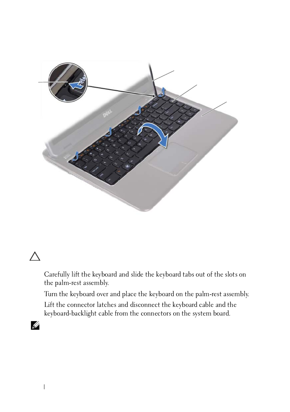
CAUTION: Exercise caution while lifting up the keyboard to avoid pulling the
keyboard connector from the system board forcefully.
6
7
8
NOTE: The keyboard-backlight cable is available only if you purchased a back-lit
keyboard.
1 tabs (4) 2 plastic scribe
3 keyboard 4 palm-rest assembly
1
2
4
3

Keyboard 33
9
Replacing the Keyboard
1
2
3
4
5
1 keyboard-cable connector 2 keyboard-backlight cable connector
3 keyboard
2
1
3

34 Keyboard

Palm-Rest Assembly 35
9
Palm-Rest Assembly
WARNING: Before working inside your computer, read the safety information
that shipped with your computer. For additional safety best practices information,
see the Regulatory Compliance Homepage at dell.com/regulatory_compliance.
CAUTION: To avoid electrostatic discharge, ground yourself by using a wrist
grounding strap or by periodically touching an unpainted metal surface (such as a
connector on your computer).
CAUTION: Only a certified service technician should perform repairs on your
computer. Damage due to servicing that is not authorized by Dell is not covered by
your warranty.
CAUTION: To help prevent damage to the system board, remove the main battery
(see "Removing the Battery" on page 13) before working inside the computer.
Removing the Palm-Rest Assembly
1
Follow the instructions in "Before You Begin" on page 9.
2
Remove the battery. See "Removing the Battery" on page 13.
3
Remove the module cover. See "Removing the Module Cover" on page 15.
4
Follow the instructions from step 4 to step 5 in "Removing the Optical
Drive" on page 23.
5
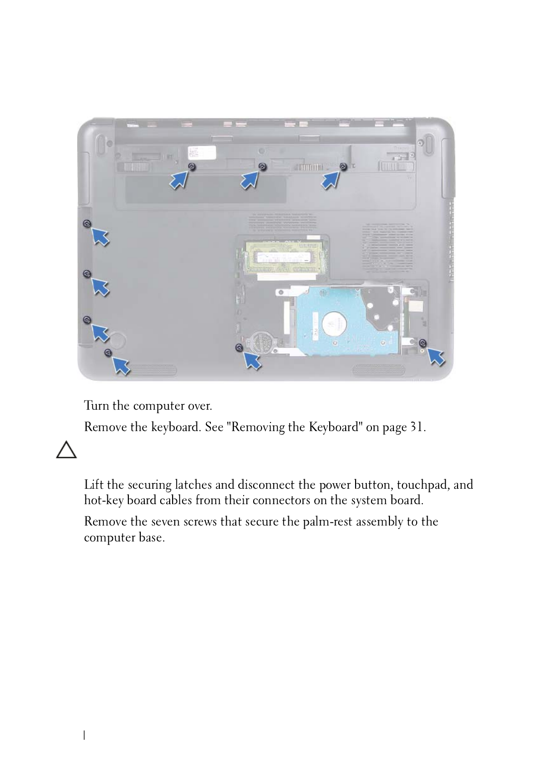
Remove the nine screws that secure the palm-rest assembly to the
computer base.
36 Palm-Rest Assembly
6
7
CAUTION: Pull on the plastic tab on top of the connectors to avoid damaging the
connectors.
8
9

Palm-Rest Assembly 37
CAUTION: Separate the palm-rest assembly from the computer base carefully to
avoid damage to the palm-rest assembly and the display.
10
Lift the palm-rest assembly off the computer base.
1 screws (7) 2 power-button cable connector
3 hot-key board cable connector 4 touchpad-cable connector
5 palm-rest assembly
3
1
4
2
5

38 Palm-Rest Assembly
Replacing the Palm-Rest Assembly
1
2
3
4
5
6
7
8
1 palm-rest assembly
1

Palm-Rest Assembly 39
9
CAUTION: Before turning on the computer, replace all screws and ensure that no
stray screws remain inside the computer. Failure to do so may result in damage to
the computer.

40 Palm-Rest Assembly

Wireless Mini-Card 41
10
Wireless Mini-Card
WARNING: Before working inside your computer, read the safety information
that shipped with your computer. For additional safety best practices information,
see the Regulatory Compliance Homepage at dell.com/regulatory_compliance.
CAUTION: Only a certified service technician should perform repairs on your
computer. Damage due to servicing that is not authorized by Dell is not covered by
your warranty.
CAUTION: To avoid electrostatic discharge, ground yourself by using a wrist
grounding strap or by periodically touching an unpainted metal surface, such as a
connector on your computer.
CAUTION: To help prevent damage to the system board, remove the main battery
(see "Removing the Battery" on page 13) before working inside the computer.
CAUTION: When the mini-card is not in the computer, store it in protective
antistatic packaging. See "Protecting Against Electrostatic Discharge" in the
safety instructions that shipped with your computer.
NOTE: Dell does not guarantee compatibility or provide support for mini-cards from
sources other than Dell.
NOTE: If you ordered a wireless mini-card with your computer, the card is already
installed.
Removing the Mini-Card
1
2
3
4
5

42 Wireless Mini-Card
6
7
8
9
10
Replacing the Mini-Card
1
NOTE: Your computer can support either one Wi-Fi+WiMax mini-card or one
Wi-Fi+Bluetooth combo card at a time.
2
1 mini-card 2 screw
2
1

Wireless Mini-Card 43
CAUTION: Use firm and even pressure to slide the mini-card into place. If you use
excessive force, you may damage the connector.
CAUTION: The connectors are keyed to ensure correct insertion. If you feel
resistance, check the connectors on the mini-card and on the system board, and
realign the mini-card.
CAUTION: To avoid damage to the mini-card, never place cables under the mini-
card.
3
4
5
6
7
8
9
10
11
12
13

44 Wireless Mini-Card

Display 45
11
Display
WARNING: Before working inside your computer, read the safety information
that shipped with your computer. For additional safety best practices information,
see the Regulatory Compliance Homepage at dell.com/regulatory_compliance.
CAUTION: Only a certified service technician should perform repairs on your
computer. Damage due to servicing that is not authorized by Dell is not covered by
your warranty.
CAUTION: To avoid electrostatic discharge, ground yourself by using a wrist
grounding strap or by periodically touching an unpainted metal surface (such as a
connector on your computer).
CAUTION: To help prevent damage to the system board, remove the main battery
(see "Removing the Battery" on page 13) before working inside the computer.
Display Assembly
Removing the Display Assembly
1
2
3
4
5

Display 47
15
Replacing the Display Assembly
1
2
NOTE: Ensure that no cables are caught between the display assembly and
the computer base.
3
1 screws (2) 2 display assembly
3 mini-card antenna cables 4 camera-cable connector
5 display-cable connector
2
1
5
4
3

48 Display
4
5
6
7
8
9
10
11
12
13
CAUTION: Before turning on the computer, replace all screws and ensure that no
stray screws remain inside the computer. Failure to do so may result in damage to
the computer.
Hinge Cover
Removing the Hinge Cover
CAUTION: The hinge caps are extremely fragile. Be careful when removing the
hinge caps to prevent damaging them.
1
2
3
4
5

Display 49
6
7
8
9
Replacing the Hinge Cover
1
2
3
1 screws (2) 2 tabs (6)
2
1
50 Display
4
5
6
7
8
9
CAUTION: Before turning on the computer, replace all screws and ensure that no
stray screws remain inside the computer. Failure to do so may result in damage to
the computer.
Display Bezel
Removing the Display Bezel
1
2
CAUTION: The display bezel is extremely fragile. Be careful when removing the
bezel to prevent damage.
3
4
Display 51
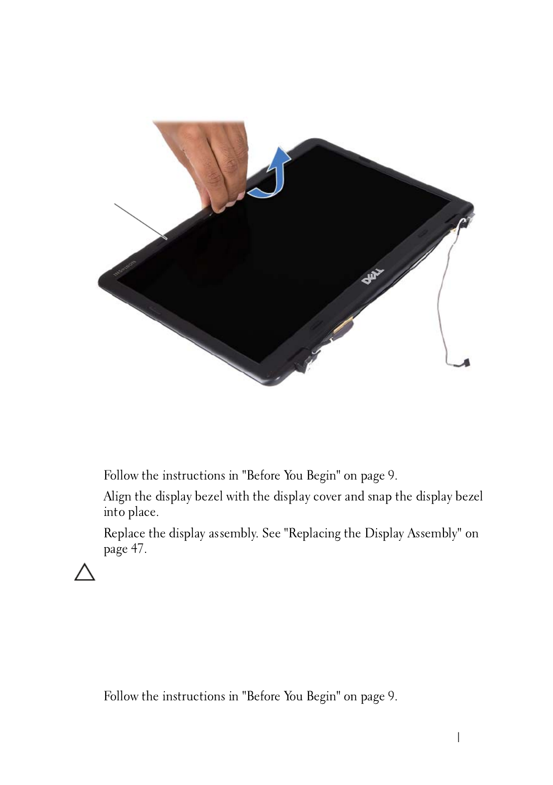
Replacing the Display Bezel
1
2
3
CAUTION: Before turning on the computer, replace all screws and ensure that no
stray screws remain inside the computer. Failure to do so may result in damage to
the computer.
Display Panel
Removing the Display Panel
1
1 display bezel
1

52 Display
2
3
4
5
6
7
1 screws (4) 2 display panel
1
2
Display 53
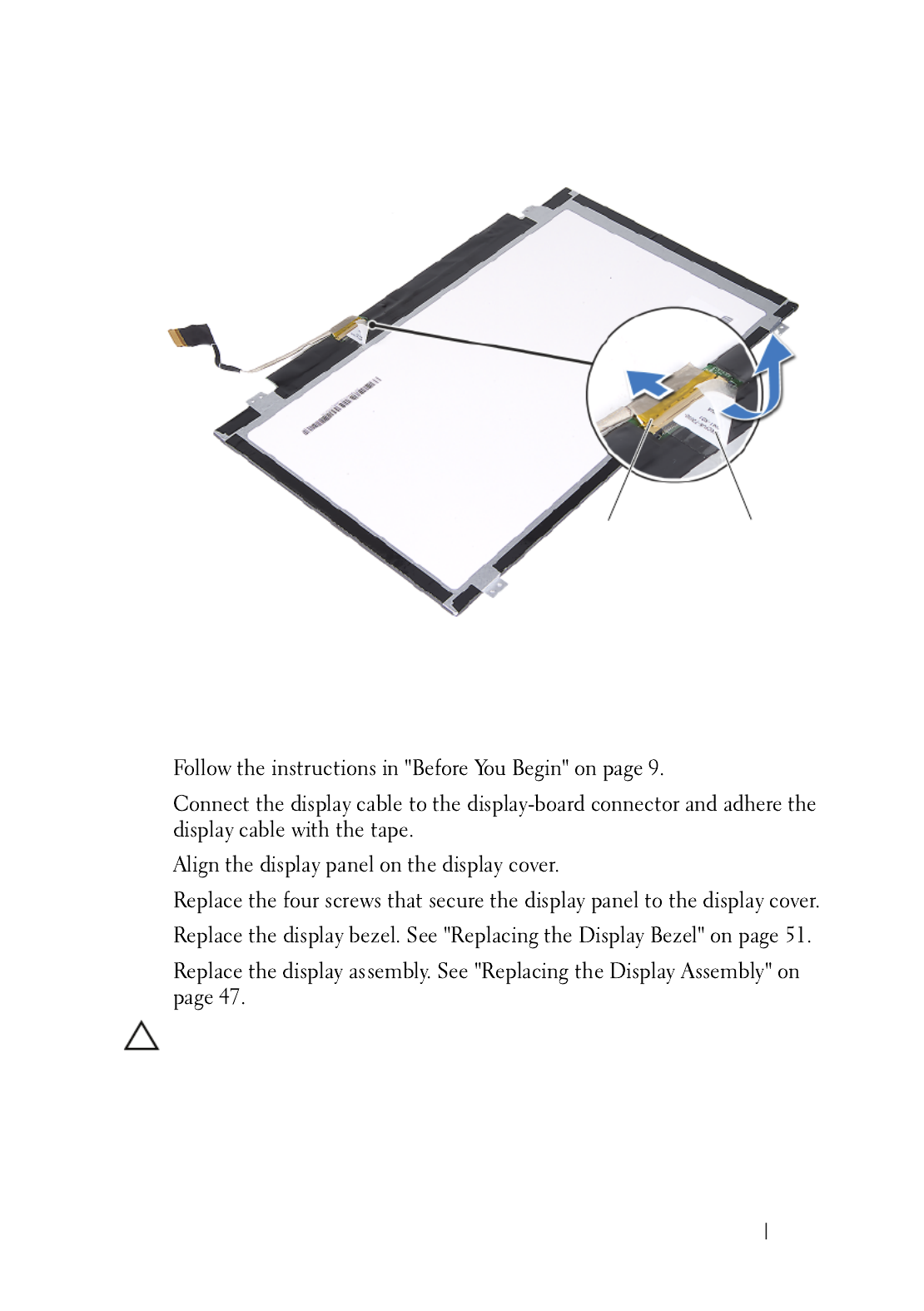
Replacing the Display Panel
1
2
3
4
5
6
CAUTION: Before turning on the computer, replace all screws and ensure that no
stray screws remain inside the computer. Failure to do so may result in damage to
the computer.
1 display-cable connector 2 tape
1 2

54 Display
Hinge Assembly
Removing the Hinge Assembly
1
2
3
4
5
6
Replacing the Hinge Assembly
1
1 screws (6) 2 hinge assembly
2
1

Display 55
2
3
4
5
6
CAUTION: Before turning on the computer, replace all screws and ensure that no
stray screws remain inside the computer. Failure to do so may result in damage to
the computer.
Produkt Specifikationer
| Mærke: | Dell |
| Kategori: | Laptop |
| Model: | XPS 14z |
Har du brug for hjælp?
Hvis du har brug for hjælp til Dell XPS 14z stil et spørgsmål nedenfor, og andre brugere vil svare dig
Laptop Dell Manualer

10 Januar 2025
30 December 2025
8 December 2024
8 December 2024
8 December 2024
8 December 2024
8 December 2024
9 Oktober 2024
5 Oktober 2024
22 September 2024
Laptop Manualer
- Laptop Acer
- Laptop Sony
- Laptop Samsung
- Laptop Panasonic
- Laptop LG
- Laptop Apple
- Laptop HP
- Laptop Asus
- Laptop Gigabyte
- Laptop Toshiba
- Laptop Lenovo
- Laptop Thomson
- Laptop Hannspree
- Laptop Razer
- Laptop Medion
- Laptop Haier
- Laptop Huawei
- Laptop Tripp Lite
- Laptop Packard Bell
- Laptop Microsoft
- Laptop Fellowes
- Laptop Xiaomi
- Laptop Viewsonic
- Laptop Fujitsu
- Laptop MSI
- Laptop Honor
- Laptop ECS
- Laptop Prixton
- Laptop SPC
- Laptop GoClever
- Laptop VIZIO
- Laptop Atdec
- Laptop Hercules
- Laptop Airis
- Laptop EMachines
- Laptop Oregon Scientific
- Laptop Lexibook
- Laptop Kogan
- Laptop ADATA
- Laptop Micromax
- Laptop TechBite
- Laptop Alienware
- Laptop Sylvania
- Laptop Coby
- Laptop Evga
- Laptop Mpman
- Laptop Targa
- Laptop Peaq
- Laptop Ematic
- Laptop XPG
- Laptop Inovia
- Laptop Aplic
- Laptop Odys
- Laptop Ibm
- Laptop Compaq
- Laptop SIIG
- Laptop Getac
- Laptop Jay-tech
- Laptop Vulcan
- Laptop System76
- Laptop General Dynamics Itronix
- Laptop CTL
- Laptop Everex
- Laptop Olidata
- Laptop Dynabook
- Laptop Hamilton Buhl
- Laptop AORUS
- Laptop Humanscale
- Laptop Schenker
Nyeste Laptop Manualer

5 Februar 2025

12 Januar 2025
12 Januar 2025

12 Januar 2025

12 Januar 2025
12 Januar 2025
11 Januar 2025
11 Januar 2025
11 Januar 2025
10 Januar 2025