Festo P.BE-CMMP-SC-SW-IT Manual
Festo
Ikke kategoriseret
P.BE-CMMP-SC-SW-IT
Læs nedenfor 📖 manual på dansk for Festo P.BE-CMMP-SC-SW-IT (126 sider) i kategorien Ikke kategoriseret. Denne guide var nyttig for 13 personer og blev bedømt med 4.5 stjerner i gennemsnit af 2 brugere
Side 1/126
SERCOS for Motor Controller
CMMP…
Manual
SERCOS
CMMP…
Manual
557 362
en 0708NH
[723 778]


P.BE-CMMP- - - - 0708NH 3 AS SC SW EN
Edition __________________________________________________ 0708NH en
Designation __________________________________ P.BE-CMMP- - - - AS SC SW EN
Order no. ___________________________________________________ 557 362
( 2008)Festo SE & Co KG., D-73726 Esslingen,
Internet: http://www.festo.com
E-mail: service_international@festo.com
The copying, distribution and utilization of this document as well as the communication of
its contents to others without expressed authorization is prohibited. Offenders will be held
liable for the payment of damages. All rights reserved in particular the right to register
patents, utility models and designs.

4 P.BE-CMMP- - - - 0708NHAS SC SW EN
Record of changes
Authors
Festo SE & Co KG
Manual name:
P.BE-CMMP- - - -AS SC SW EN
File name:
File location:
Ser. no.
Approval for distribution
Versions index
Date of change
1
Creation
0708NH
11.03.2008
Trademarks
Microsoft and Windows are registered trademarks or trademarks of the Microsoft
Corporation in the USA and/or others countries.

P.BE-CMMP- - - - 0708NH 5 AS SC SW EN
Tab Contents le of
Copyrights
Festo SE Rights & Co KG. All Reserved.
T informatio an dat documen have bee pu toge base ou best he n d a in this t n t ther d on r
knowledge Bu differences betwee the documen an produc cann b completely . t n t d t ot e
exclud F guarantees the devices an rela softwar versied. esto d ted e in the on issued to
customers wh u accordanc w contr an u documentation. I case en sed in e ith the act d the ser n
of serious deviations fro user documentatim the on, Fest entitle an obligated to make o is d d
repairs unle woul resu unreasonab cost liabili results fr defects ss this d lt in le s. No ty om
aris fr u und cond intended for dev describ user ing om se er itions not the ice as ed in the
documentation.
Fest do guarante produ requiremen an purp the o es not e that the cts suit the ts d oses of
buye they wil w toge wi othe produ selecte b th buyer Festo r or that l ork ther th r cts d y e .
accep liabili f damag resu from u its produ togeth wi other ts no ty or es lting se of cts er th
products or of or from improper handling the devices systems.
Festo SE & Co the the KG reserves right to change, improve supplement or document or
product without prior notice.
T documen who part may not b reproduced tran i another natural his t, in le or in , e , slated nto
or machine-legib language, or transferrle ed ont electroni mechanical optic any o c, , al or
other typ d medi withou expr approv author. e of ata a t the ess al of the
Trademarks
Produ nam documen may b register trademark T solct es in this t e ed s. he e purp of ose
trademark documen is to identif correspond products. s this in t y the ing
SE interface is a regist tradem interest group association RCOS ® ered ark of the
Interessengemei SE interf E.V. nschaft RCOS ace

Table of Contents
6 P.BE-CMMP- - - - 0708NH AS SC SW EN
Table of Contents
1. General information .............................................................................................. 9
1.1 Documentation .................................................................................................... 9
1.2 Serial realtime communication system (SErial Realtime COmmunication System) 10
2. Safety instructions for electrical drives and controllers ...................................... 11
2.1 Symbols used .................................................................................................... 11
2.1.1 Other symbols .................................................................................... 11
2.2 General information ........................................................................................... 12
2.2.1 Trained and qualified personnel ......................................................... 12
2.3 Hazards due to improper use ............................................................................. 13
2.4 Safety instructions ............................................................................................. 14
2.4.1 General safety information ................................................................. 14
2.4.2 Safety instructions for installation and maintenance .......................... 16
2.4.3 Protection against touching electrical parts ........................................ 17
2.4.4 Protection from electric shock through protective extra-low voltage with
secure separation (PELV) .................................................................... 19
2.4.5 Protection against touching electrical parts ........................................ 20
2.4.6 Protection during handling and installation ........................................ 20
3. Cabling and pin assignment ................................................................................ 21
4. Activation of SERCOS .......................................................................................... 23
4.1 Overview ........................................................................................................... 23
5. Overview ............................................................................................................. 25
5.1 Overview communication ................................................................................... 25
5.2 Axis telegram (AT) .............................................................................................. 26
5.3 Master data telegram (MDT) .............................................................................. 27
5.4 Service channel (SC) .......................................................................................... 27
5.5 Telegram types .................................................................................................. 28
5.5.1 Standard telegrams ............................................................................ 28
5.5.2 Application telegram .......................................................................... 29
5.6 Initialisation (phase change) .............................................................................. 30
5.6.1 Communication Phase 0: Closing the ring ........................................... 30
5.6.2 Communication Phase 1: Identification of the drives .......................... 30
5.6.3 Communication Phase 2: Loading the communication parameters ..... 30
5.6.4 Communication Phase 3: Loading the communication parameters ..... 31
5.6.5 Communication Phase 4: Cycle operation ........................................... 31

Table of Contents
P.BE-CMMP- - - - 0708NH 7 AS SC SW EN
6. SERCOS cycletime ............................................................................................... 32
7. Operation modes ................................................................................................. 33
7.1 Torque control ................................................................................................... 34
7.2 Velocity control .................................................................................................. 34
7.3 Position control ................................................................................................. 34
7.4 Drive-internal interpolation ................................................................................ 34
8. Scaling of data .................................................................................................... 35
8.1 Position data ..................................................................................................... 35
8.1.1 Overview ............................................................................................ 35
8.1.2 Unscaled ............................................................................................ 36
8.1.3 Translatory scaling ............................................................................. 36
8.1.4 Rotatory scaling ................................................................................. 36
8.2 Velocity data ...................................................................................................... 37
8.2.1 Overview ............................................................................................ 37
8.2.2 Unscaled ............................................................................................ 38
8.2.3 Translatory scaling ............................................................................. 38
8.2.4 Rotatory scaling ................................................................................. 38
8.3 Acceleration data ............................................................................................... 39
8.3.1 Overview ............................................................................................ 39
8.3.2 Unscaled ............................................................................................ 40
8.3.3 Translatory scaling ............................................................................. 40
8.3.4 Rotatory scaling ................................................................................. 40
8.4 Torque data ....................................................................................................... 40
8.5 Temperature data .............................................................................................. 40
9. Control word/status word ................................................................................... 41
10. 44 Error management ..............................................................................................
11. I/O functions ....................................................................................................... 45
12. Special commands .............................................................................................. 46
12.1 Drive-controlled homing .................................................................................... 46
12.2 Spindle positioning ............................................................................................ 48
12.3 Probing (measurement) ..................................................................................... 49
12.4 Automatic motor identification .......................................................................... 50
13. Parameters .......................................................................................................... 52
13.1 Overview ........................................................................................................... 52
13.1.1 Communication parameters ............................................................... 52

Table of Contents
8 P.BE-CMMP- - - - 0708NH AS SC SW EN
13.2 Telegram configuration ...................................................................................... 59
13.3 IDN lists/phase switching commands ................................................................ 62
13.4 Operation modes ............................................................................................... 66
13.5 Scaling parameter ............................................................................................. 67
13.6 Command/feedback values ............................................................................... 73
13.7 Limitation/monitoring ....................................................................................... 75
13.8 Signal status word/realtime bits ........................................................................ 81
13.9 Status bits ......................................................................................................... 85
13.10 Automatic identification ..................................................................................... 91
13.11 Error management ............................................................................................. 92
13.12 I/O functions ..................................................................................................... 93
13.13 Drive-controlled homing .................................................................................... 96
13.14 Drive-internal interpolation ................................................................................ 99
13.15 Probes ............................................................................................................. 101
13.16 Spindle positioning .......................................................................................... 103
13.17 Other accessories ............................................................................................ 105
13.18 Information ...................................................................................................... 108
13.19 Diagnosis classes ............................................................................................ 112
13.19.1 Diagnosis class 1 (condition class 1) ................................................ 112
13.19.2 Manufacturer diagnosis class 1 ........................................................ 113
13.19.3 IDN S-0-0095: Diagnostic message ................................................... 113
13.19.4 Diagnosis class 2 (condition class 2) ................................................ 114
13.19.5 Diagnosis class 3 (condition class 3) ................................................ 115
13.19.6 Manufacturer diagnosis class 3 (condition class 3) ........................... 116
13.19.7 IDN S-0-0014: "Interface status" ...................................................... 116
13.19.8 Diagnosis masks .............................................................................. 118
14. SERCOS error codes .......................................................................................... 119
A. Appendix ........................................................................................................... 121
B. Index ................................................................................................................. 122

1 General information .
P.BE-CMMP-AS- - - 0708NH 9 SC SW EN
1. General information
1.1 Documentation
This manual describes the field bus connection of CMMP-AS servo positioning SERCOS
controllers under SERCOS. It briefly describes the protocol itself, activation of SERCOS
communication and the parameters available under SERCOS.
It is directed at people who are already familiar with servo positioning controllers and the
SERCOS protocol.
It contains safety instructions that must be followed.
For additional information, please consult the following handbooks for products of the
series CMMP-AS:
Product manual “Servo Positioning Controllers AS” P.BE-CMMP- :
Description of the technical specification and function of the device as well as
information on installation and operation of the servo positioning controller
P.BE-CMMP- -...-3A for 1-phase servo positioning controllers. AS
Product manual “Servo Positioning Controllers AS” P.BE-CMMP- :
Description of the technical data and function of the device with information on
installation and operation of the P.BE-CMMP- -...-11A for 3-phase servo positioning AS
controllers.
CANopen - manual “Servo Positioning Controllers CMMP AS”:
Description of the implemented CANopen protocol in accordance with DSP402:
P.BE-CMMP-CO- SW
PROFIBUS manual “Servo Positioning Controllers CMMP AS”- :
Description of the implemented PROFIBUS-DP protocol: P.BE-CMMP-FHPP- - PB SW
Product manual "Ethernet Technology Module":
Description of the technical data and function of the device with information on
installation and operation of the Ethernet technology module: P.BE-CMMP- - ET SW

1 General information .
10 P.BE-CMMP- - - - 0708NH AS SC SW EN
1.2 Serial realtime communication system
(SErial Realtime COmmunication System)
SERCOS interface, the unique, worldwide standardised (IEC 61491 and EN 61491) digital
interface for communication between control systems and drives. It was the first field bus
system that permitted achievement of numerically controlled high-performance
applications in machine tooling.
A glass-fibre ring is used as transmission medium. The transfer rate is 2, 4, 8 or 16 Mbit/s.
With this interface, essentially three types of communication can be achieved between
CNC and digital drive-control elements:
Transmission of the nominal position value
Transmission of the nominal speed
Transmission of the nominal torque
Transmission of the nominal position value proved to be the best solution for rapid and
highly precise applications. In a fibre-optic cable ring, up to six axes can be provided with
new position command values (setpoint positions)cyclically and parallel every 0.5 ms.
The SERCOS interface permits display of all drive-internal data, parameters and diagnostic
information as well as their input using a SERCOS-compatible CNC.
2 Safety instructions for electrical drives and controllers .
P.BE-CMMP-AS- - - 0708NH SC SW EN 11
2. Safety instructions for electrical drives and
controllers
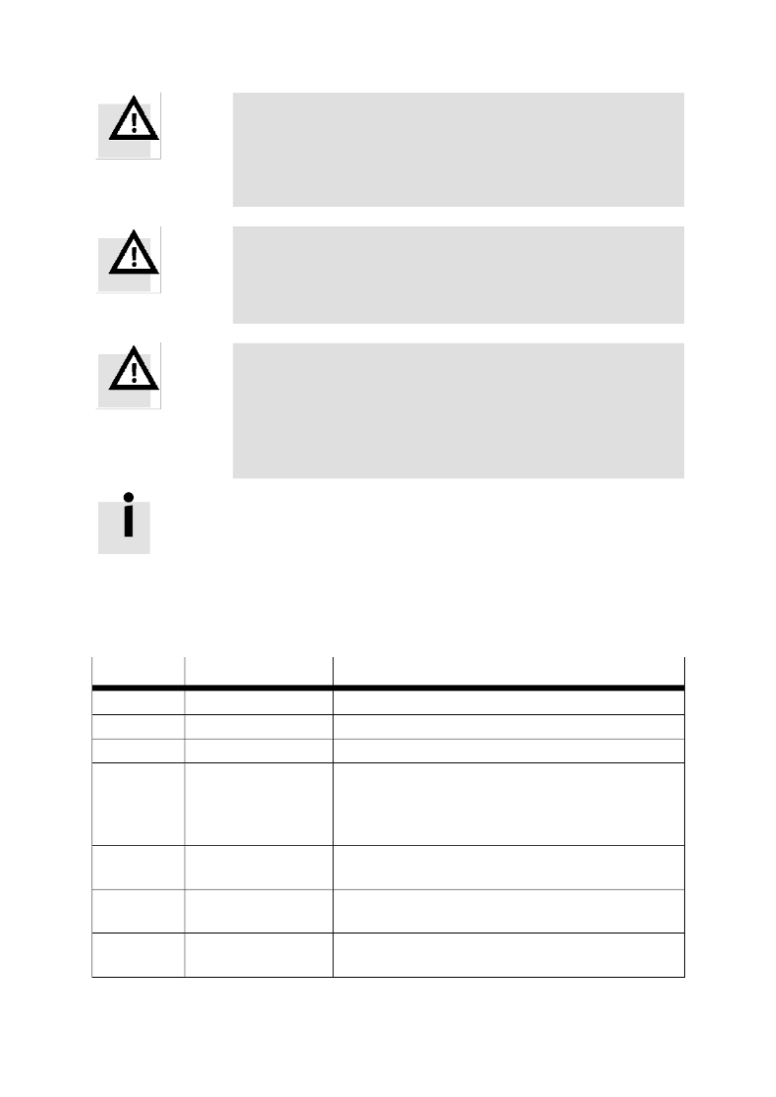
2.1 Symbols used
Information
Important information and remarks.
Careful!
Failure to comply can result in severe property damage.
DANGER!
Failure to comply can result in property damage and personal
injury.
Careful! Deadly voltage levels.
The safety instructions point out potentially deadly voltage levels.
Accessory
Environment
2.1.1 Other symbols
Diskette
symbol
All the following steps affect the settings in the Festo
ServoCommanderTM parameterisation program.
Plug symbol
All of the following steps affect the hardware, i.e. the CMMP-AS servo
positioning controller.

2 Safety instructions for electrical drives and controllers .
12 P.BE-CMMP- - - - 0708NH AS SC SW EN
2.2 General information
Festo accepts no liability for damage due to failure to comply with the safety instructions
in this manual.
Before placing into operation, read the chapter "Safety instructions
for electrical drives and controllers", starting from page 11.
If you do not exactly understand the documentation in this language, please contact and
inform your supplier.
The defect-free and secure operation of the servo positioning controller requires proper
and correct transport, proper and correct storage, mounting and installation as well as
proper operation and maintenance. Only trained and qualified personnel should use
electrical devices.
2.2.1 Trained and qualified personnel
as defined by this product manual or the safety instructions on the product itself are
people who are sufficiently familiar with the set-up, mounting, start-up and operation of
the product as well as with all warnings and precautionary measures in accordance with
the instructions in this manual and who are sufficiently qualified in their field.
Training and instruction or authorisation to switch the devices/systems on and off and
earth them in accordance with safety technology standardsand to mark them in
accordance with work requirements.
Training and instruction in accordance with safety technology standards regarding
maintenance and use of appropriate safety equipment.
Training in first aid.
The following instructions must be read before initial start-up of the system to prevent
personal injury and/or property damage.
Safety instructions must always be followed.
Do not attempt to install the servo positioning controller or place it
into operation until you have carefully read all safety instructions
for electrical drives and controllers in this document. These safety
instructions and all otheruser instructions must be read prior to any
work with the servo positioning controller.
If you do not have user instructions for the servo positioning
controller, please contact your sales agent. Demand that these
documents be sent immediately to the person responsible for safe
operation of the servo positioning controller.
2 Safety instructions for electrical drives and controllers .
P.BE-CMMP-AS- - - 0708NH SC SW EN 13
If you sell the device, lend it or make it available to third parties in
some other way, they must also receive these safety instructions.
For safety and warranty reasons, the user must never open the
servo positioning controller.
A proper project planning of the control process is a prerequisite
for correct functioning of the servo positioning controller!
DANGER!
Improper handling of the servo positioning controller and failure to
follow the warning instructions as well as improper tampering with
the safety equipment can result in property damage, personal in-
jury, electric shock or, in extreme cases, even in death.
2.3 Hazards due to improper use
DANGER!
High electric voltage and high load current!
Danger of death or severe personal injury due to electric shock!
DANGER!
High electric voltage from incorrect connections!
Danger of death or severe personal injury due to electric shock!
DANGER!
Surface of the device housing can be hot!
DANGER!
Dangerous movements!
Mortal danger, severe personal injury or property damage due to
unintended motor movements!
2 Safety instructions for electrical drives and controllers .
14 P.BE-CMMP- - - - 0708NH AS SC SW EN
2.4 Safety instructions
2.4.1 General safety information
The servo positioning controller equals protection class IP20 as
well as degree contamination 1. Make sure that the environment
corresponds to this protection class and degree of contamination.
Use only replacement parts and accessories approved by the
manufacturer.
In accordance with the EN standards, the devices should be con-
nected to the power network so that they can be separated from
the network with appropriate switches (e.g. main switch, contactor,
circuit breaker).
The servo positioning controller can be protected with a 300 mA
all-current-sensitive ground fault circuit interruptor
(RCD = residual current protection device).
Gold-plated contacts or contacts with high contact pressure should
be used for switching the control contacts.
For switchboards precautionary error-clearing measures should be
taken, such as wiring of fuses and relays with RC members or
diodes.
The safety regulations and stipulations of the country in which the
device is used must be followed.
The environmental conditions specified in the product documenta-
tion must be followed. Safety-critical applications are not permitted
unless expressly approved by the manufacturer.
The information for an EMC-suitable installation should be taken
from the product manual of the CMMP-AS family. Compliance with
the limit values required by national regulations is the responsi-
bility of the manufacturer of the device or system.

2 Safety instructions for electrical drives and controllers .
P.BE-CMMP-AS- - - 0708NH SC SW EN 15
The technical data and connection and installation conditions for
the servo positioning controller must be taken from this product
manual and complied with.
DANGER!
The general erection and safety regulations for work on high
voltage systems (e.g. DIN, VDE, EN, IEC or other national and
international regulations) must be followed.
Failure to comply can result in personal injury or major property
damage.
The following precautionary measures also apply without claim to
completeness:
VDE 0100 Specifications for installation of high voltage devices
(up to 1000 V),
EN 60204 Electrical Equipment of Machines,
EN 50178 Electronic Equipment for Use in Power Installations.
2 Safety instructions for electrical drives and controllers .
16 P.BE-CMMP- - - - 0708NH AS SC SW EN
2.4.2 Safety instructions for installation and maintenance
The corresponding DIN, VDE, EN and IEC instructions as well as all national and local safety
and accident protection regulations apply for the installation and maintenance of the
system. The operating engineer or user is responsible for compliance with these
regulations.
Operation, maintenance and/or repairs on the servo positioning
controller may only be performed by personnel who have been
trained and qualified for work on or with electrical devices.
Avoidance of accidents, injuries and/or damage:
The motor-stop brake delivered standard, or an external motor-stop
brake actuated only by the drive control device, is not suited for
protecting personnel.
Also secure vertical axes against falling or dropping after the
motor has been shut off, such as by:
mechanical locking of the vertical axis,
external brake, catch or clamping device, or
sufficient balancing of the axis.
The external or internal brake resistance results in danagerous
direct voltage during operation of the servo positioning controller
and up to 5 minutes afterward. Contact can result in death or
severe personal injury.
Switch off power to the electrical equipment using the main switch
and secure it against being switched back on until the direct
current circuit is discharged during:
servicing and preventive maintenance,
cleaning work,
long standstill times.
Before performing maintenance work, make sure that the power
supply has been switched off and locked and that the direct current
circuit has been discharged.
Be careful during installation. During installation and later, when
the drive is operated, make sure that no drill shavings, metal dust
or mounting parts (screws, nuts, cable sections) fall into the device.
Make sure that the external poser supply for the controller (24 V) is
switched off.
2 Safety instructions for electrical drives and controllers .
P.BE-CMMP-AS- - - 0708NH SC SW EN 17
The direct current circuit or power supply must always be shut off
before switching off the 24 V-controller power supply.
Work in the machine area may only be performed when the alter-
nating and/or direct current supply is shut off. Switched-off output
stages or controller enables are not suitable locking means. In case
of malfunction, the drive can be activated by mistake.
Initial start-up should be performed with motors running at idle to
prevent mechanical damage, e.g. due to incorrect rotation
direction.
Electronic devices are never fail-safe. The user is responsible for
ensuring that the system is brought into a safe condition if there is
a disturbance in an electrical device.
The servo positioning controller and, in particular, the brake
resistance, external or internal, can reach high temperatures, which
can cause serious burns.
2.4.3 Protection against touching electrical parts
This section refers only to devices and drive components with voltages above 50 V.
Touching parts with voltages above 50 V can be dangerous for people and trigger an
electric shock. During operation of electric devices, some parts of these devices
unavoidably have dangerous voltages.
DANGER!
Hohe voltage!
Mortal danger, danger of an electric shock or serious personal
injury!
2 Safety instructions for electrical drives and controllers .
18 P.BE-CMMP- - - - 0708NH AS SC SW EN
The corresponding DIN, VDE, EN and IEC instructions as well as all national and local safety
and accident protection regulations apply for the installation and maintenance of the
system. The operating engineer or user is responsible for compliance with these
regulations:
Before switching on the device, install the corresponding covers
and safety guards for protection against accidental contact.
Installed devices must be protected against accidental touching
through a housing, such as an electrical cabinet. The regulation
VBG4 must be followed!
Maintain the minimum copper diameter for the earth wire over its
entire length in accordance with EN 60617!
Always connect the earthed conductor of all electrical devices
before initial start-up, even for brief measurement or test purposes,
in accordance with the connection plan or connect it to the earthing
conductor. Otherwise, the housing can carry high voltages, which
can cause an electric shock.
Do not touch the electrical connections of the components when
they are switched on.
Separate the device from the mains or power supply before
accessing electrical parts with voltages above 50 V.
Secure it against being switched back on.
The level of the direct voltage must be considered for the installa-
tion, in particular with regard to insulation and safety measures.
Make sure there is correct earthing, conductor dimensions and
appropriate short-circuit protection.
DANGER!
The device has a fast discharge switch for the direct current circuit
in accordance with EN 60204, Section 6.2.4. But the fast discharge
may be ineffective in specific device arrangements, especially when
several servo drive controllers are switched in parallel in the direct
current circuit or when a brake resistance is not connected.
The servo drive controllers can remain under voltage for up to
5 minutes after they are switched off (residual condensor charge).

2 Safety instructions for electrical drives and controllers .
P.BE-CMMP-AS- - - 0708NH SC SW EN 19
2.4.4 Protection from electric shock through protective
extra-low voltage with secure separation (PELV)
All connections and terminals with voltages between 5 and 50 V on the servo positioning
controller are safety extra-low voltages, which are designed as touch-secure in accordance
with the following standards:
- International: IEC 60364-4- 41,
- European countries within the EU: EN 50178/1998, Section 5.2.8.1.
DANGER!
High electric voltage due to incorrect connections!
Mortal danger, danger of injury from electric shock.
Only devices, electrical components and lines with protective extra-low voltage with secure
separation (PELV = Protective Extra Low Voltage) can be connected to connections and
terminals with voltages between 0 and 50 V.
Connect only to voltages and current circuits with protection against dangerous voltages.
This protection can be achieved with the help of isolating transformers, secure optical
couplers or battery operation.
Protection against dangerous movements
Dangerous movements can be caused by faulty control of connected motors, which can
have various reasons:
incorrect or faulty wiring or cabling,
errors in operation of components,
errors in sensors or measuring transformers,
defects or non-EMC-appropriate components,
errors in the software in the higher-level control system.
These errors can occur directly after the device is switched on or after an unspecified
duration of operation.
The monitoring devices of the drive components largely exclude improper functions of the
connected drives. One cannot rely exclusively on this with regard to protection of persons,
in particular against injuries and/or property damage. Until the installed monitoring
devices become effective, defective drive movements must be expected, the extent of
which depends on the type of control and operating condition.
DANGER!
Dangerous movements!
Mortal danger, injury, serious personal or property damage!
2 Safety instructions for electrical drives and controllers .
20 P.BE-CMMP- - - - 0708NH AS SC SW EN
For the above reasons, protection of persons must be ensured with the help of monitoring
or higher-level measures for the device. These are set up in agreement with the specific
data of the system and a hazard and error analysis of the manufacturer. The safety
regulations applicable for the system are also taken into account. Accidental movements
or other malfunctions can be caused by switching off the safety devices, bypassing them or
not activating them.
2.4.5 Protection against touching electrical parts
DANGER!
Housing surfaces can be hot!
Danger of injury! Danger of burns!
Danger of burns!
Do not touch any housing surfaces in the proximity of heat
sources! Danger of burns!
After switching them off, let the devices cool off for 10 minutes
before touching.
Touching hot equipment parts which contain cooling elements
and resistances, such as the housing, can cause burns!
2.4.6 Protection during handling and installation
Handling and installation of specific parts and components in an inappropriate way can
result in burns.
DANGER!
Risk of injury due to incorrect handling!
Personal injury due to squeezing, shearing, cutting, hitting!
The following general safety instructions apply:
Follow the general set-up and safety regulations on handling
and installation.
Use suitable installation and transport device s.
Prevent pinching and squeezing with suitable safety measures.
Use only suitable tools. When specified, use special tools.
Use hoists and tools properly.
Use suitable protective equipment, when necessary
(e.g. safety goggles, work gloves, protective gloves).
Do not stand below suspended loads.
Immediately remove liquids from the floor to prevent slipping.
3 Cabling and pin assignment .
P.BE-CMMP-AS- - - 0708NH SC SW EN 21
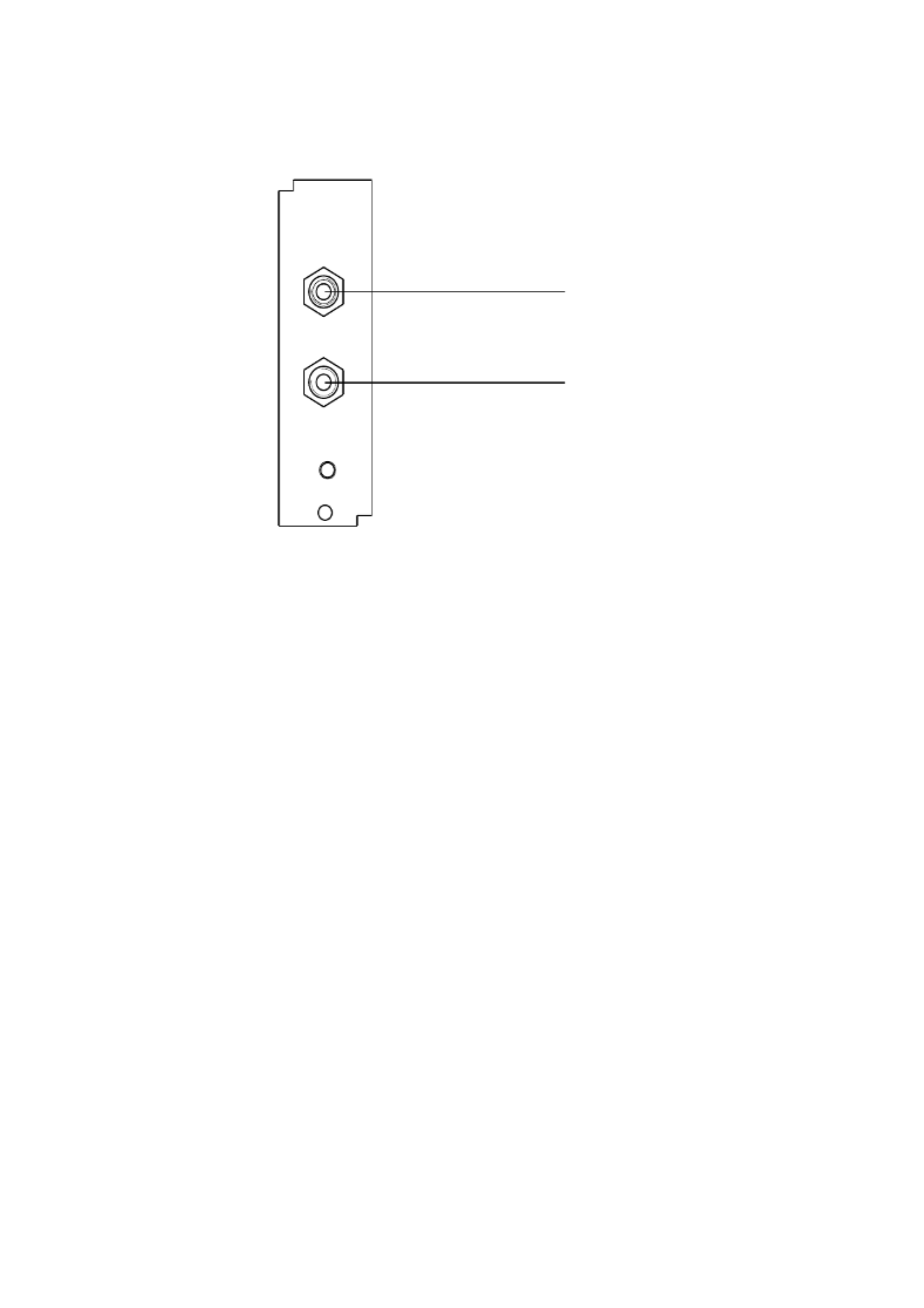
3. Cabling and pin assignment
1 Receiver
2 Transmitter
Fig. 3.1: Connection allocation
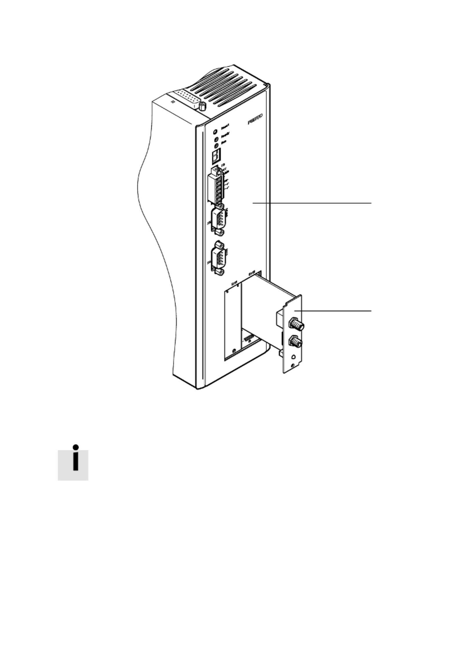
In the product assortment CMMP-AS, the SERCOS interface was implemented in the form
of an optional plug-in module. Due to special hardware requirements, it can only be used
on the Ext2 plug-in position.
In agreement with the SERCOS specification, the transmitter HFE 7000-210
(plastic housing) and the receiver HFD 7000-402 (metal housing) are accessible at the
front panel.
1
2
3 Cabling and pin assignment .
22 P.BE-CMMP- - - - 0708NH AS SC SW EN
1 CMMP- AS
2 CAMC- SC
Fig. 3.2: Plug position for CMMP- AS
Please follow the recommendations of the Interessengemeinschaft
SERCOS interface for setting up a SERCOS network.
1
2
4 Activation of SERCOS .
P.BE-CMMP-AS- - - 0708NH SC SW EN 23
4. Activation of SERCOS
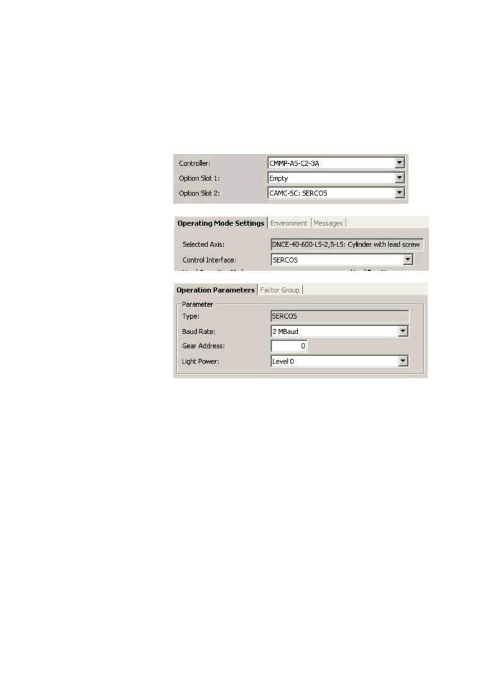
4.1 Overview
Activation of SERCOS is carried out once using the serial interface (RS232) of the servo
controller. To activate the SERCOS protocol, several settings must be made in the start-up
program.
1. In the
"Configuration" window
2. In the
"Application data"
window
3. In the
"Fieldbus" window
Before the SERCOS communication can be activated, three different parameters must be set:
Gear address
For unambiguous identification, every slave in the network must have a unique slave
address. As devices of the CMMP-AS series, they have only one driver per slave; the gear
address is identical to the slave address.
Baud rate
This parameter sets the baud rate used in MBaud. The possible baud rate depends on the
glass-fibre cable used and the capability of the numeric control used. If SERCOS is not
active yet, the chosen baud rate can deviate from the baud rate actually used. Therefore,
the "actual baud rate" is also shown.
Light power
Depending on the glass-fibre cable and the cable length, it may be necessary to adjust the
performance of the transmitter diodes to avoid overloading. For further information on this
parameter, please see chapter . 14
SERCOS communication can finally be activated. Please remember that the above-
mentioned parameters can only be changed if the protocol is deactivated. All parameters
are only valid if the SERCOS communication is deactivated and then reactivated.

4 Activation of SERCOS .
24 P.BE-CMMP- - - - 0708NH AS SC SW EN
Please remember that activation of the SERCOS communication
after a reset is only available if the parameter set has been stored.
Available baud rates
The following baud rates are available:
2 Mbaud
4 Mbaud
8 Mbaud
16 Mbaud
5 Overview .
P.BE-CMMP-AS- - - 0708NH SC SW EN 25
5. Overview
5.1 Overview communication
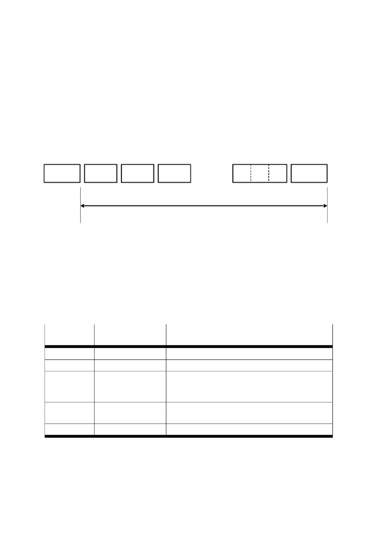
SERCOS is a Master-slave field bus system with one Master and several serially connected
slaves. The communication takes place cyclically and starts with the so-called Master
synchronisation telegram (MST). The time between two MSTs is called SERCOS cycle time
(tSCYC).
The axis telegram (AT) from each drive follows the MST. The AT contains feedback
information of the drive, e.g. position information (actual position value).
The Master data telegram (MDT) follows the ATs. The MDT contains a data record of each
slave with operating data for the drives, e.g. nominal position values.
MST
SERCOS cycle time
MSTAT1 AT2 AT3 MDT
Fig. 5.1: Cyclic exchange of data
MDT and AT are configurable, that is, the number and type of parameters that can be
cyclically exchanged can be determined by the user. In addition, data that is not time
critical can be exchanged by using the service channel. For this, a separate data container
is reserved within the MDT and AT. Transmission through the service channel takes place
in a segmented way. The service channel is also used for processing procedure commands,
such as "Drive controlled homing".
To set up a SERCOS network properly , the timing of all slaves must be configured and the
times for sending the MDTs and ATs determined. For this, initialization of the SERCOS
communication is divided into five main communication phases (CP):
Communication
phases
Purpose
Task
0
Closing the ring
The Master tests whether all slaves repeat the Master signal.
1
Identification of the axes
The Master identifies the slaves based on their gear address.
2
Loading the
communication
parameters
The Master queries the timing abilities of each drive and sets
the timing of the rings according to the timing parameters of
the drives.
3
Loading the application
parameters
Transmission of all parameters for cyclic communication,
e.g. scaling of the position values.
4
Cycle operation
Slaves operate cyclically.
Tab. 5.1: Communication phases
5 Overview .
26 P.BE-CMMP- - - - 0708NH AS SC SW EN
SERCOS defines a number of parameters for communication purposes as well as
application purposes. A unique identification number (IDN) is assigned to a parameter to
identify it. Besides the operating data, it is also possible to read off name, attribute, unit,
minimum and maximum value for each implemented IDN.
The parameters defined by the SERCOS specification are marked by an "S"‚ as in
S-0-0001. Producer-specific parameters start with a "P".
The next chapter describes the design of the SERCOS telegrams, such as AT and MDT.
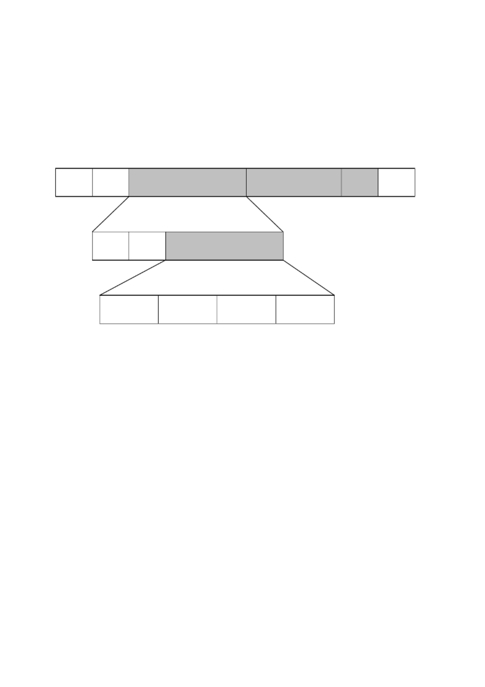
5.2 Axis telegram (AT)
The axis telegram contains the operating data of the drive. Each slave sends its own AT
with its specific gear address in the Adr field. The operating data can be configured by the
user according to the specific application; for example, the actual position value and the
actual velocityvalue can be jointly embedded.
Fig. 5.2: Axis telegram (AT)
Through a special parameter (IDN list of the configurable data in the AT), one can find out
which IDNs may be recorded in the AT.
Besides the operating data, the AT contains data of the service channel (drive service info)
and the status word with status information of the drive.
For detailed information regarding configuration of the MDT, please consult your NC
manual.
Data record
Status
Drive
service
info
Operating data
Operation data
IDN xxxx
Operation data
IDN xxxx
Operation data
IDN xxxx
Operation data
IDN xxxx
WI
5 Overview .
P.BE-CMMP-AS- - - 0708NH SC SW EN 27
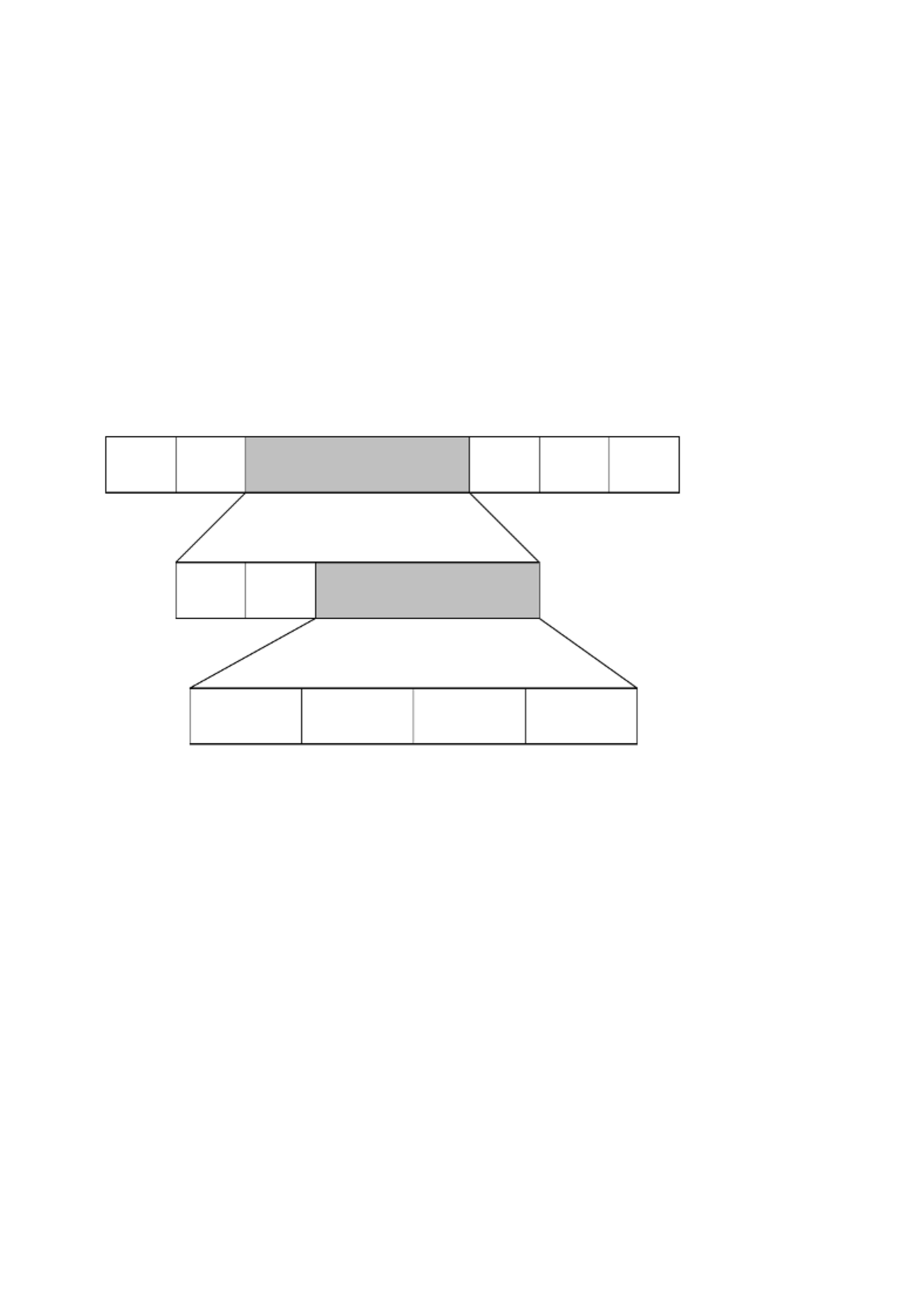
5.3 Master data telegram (MDT)
The Master data telegram contains the command values for the drives. The Master sends
only a Master data telegram with specific data records for each drive. The operating data
for the drives can be configured; for example, the position command value and the torque
limit can be jointly embedded.
Through a special parameter (IDN list of the configurable data in the MDT), one can find
out which IDNs may be recorded in the MDT.
Fig. 5.3: Master data telegram (MDT)
Similar to the design of the AT, the MDT contains service channel data (Master service info)
and the control word to control the drive.
For detailed information regarding configuration of the MDT, please consult your
NC manual.
5.4 Service channel (SC)
In addition to the cyclical data exchange, data that is not time critical can be exchanged via
the service channel. Since only 2 bytes are reserved for the service channel in the AT and
MDT, the data must be transmitted in a segmented way. A special handshake mechanism
is implemented for transmission of the data. Please refer to the SERCOS specifications for
additional information regarding the service channel mechanism.
The service channel is used frequently by NCs to display all available parameters (name,
value, etc.) and permit the user to edit them. Whether the service channel function is
available depends on your NC. For information regardin this, please consult your g
NC manual.
Addr
ess
Control
Master
service
info
Operating data
Operation data
IDN xxxx
Operation data
IDN xxxx
Operation data
IDN xxxx
Operation data
IDN xxxx
Data record 1
Data record 2
. . . .

5 Overview .
28 P.BE-CMMP- - - - 0708NH AS SC SW EN
The service channel is also used to set up the drive during initialization (phase conversion),
in order to send timing parameters to the drive and initiate switchover into the next phase
through a procedure command. A procedure command is a special type of non-cyclical data
which, when sent through the service channel, calls up established functional processes, e.g.
starting of the homing procedure. These processes can take some time. However, the service
channel is immediately available again for transmission of non-cyclical data, since the
procedure command only initiates the start of a functional process. The status of the
command is transmitted by the service channel, so the Master is able to check whether the
started command has been correctly carried out or whether it must still be carried out. As a
parameter, each procedure command is assigned a unique IDN.
5.5 Telegram types
The telegram content of the configurable data records is established by the Telegram type
parameter (S-0-0015). Either a predefined standard telegram can be selected or an
application-specific telegram used. The telegram type must be configured in phase 2.
5.5.1 Standard telegrams
Standard telegram 0
No cyclical data are being exchanged. Data can only be exchanged via the service channel.
Standard telegram 1
The standard telegram 1 can be used for the torque regulation operation mode:
Data record in the MDT
Data record in the AT
Data field 0
Data field 1
Torque command value
(S-0-0080) 2 Bytes
No data
0 Bytes
Standard telegram 3
The standard telegram 3 can be used for the velocity control operation mode:
Data record in the MDT
Data record in the AT
Data field 0
Data field 1
Data field 0
Data field 1
Velocity command value
(S-0-0036) 4 Bytes
Position feedback value
(S-0-0051) 4 Bytes
Standard telegram 4
The standard telegram 4 can be used for the position control operation mode:
Data record in the MDT
Data record in the AT
Data field 0
Data field 1
Data field 0
Data field 1
Position command value
(S-0-0047) 4 Bytes
Position feedback value
(S-0-0051) 4 Bytes

5 Overview .
P.BE-CMMP-AS- - - 0708NH SC SW EN 29
5.5.2 Application telegram
In addition to the standard telegrams, it is possible to use one's own freely configured
telegram. MDT and AT can be configured independently of each other.
The IDNs used in the MDT must be set up in S-0-0024 (Configuration list MDT). The
available parameters can be read off the IDN S-0-0188 (IDN list of all configurable data in
the MDT). The maximum permissible length in bytes can be output by S-0-0186
(IDN Length of the configurable data record in the MDT ).
The following IDNs can be used for configuration of the AT:
S-0-0016 (Configuration list AT)
S-0-0187 (IDN liste of all configurable data data in the AT)
S-0-0185 (Length of configurable data record in the AT).
It must be considered that only a limited number of data can be cyclically exchanged if low
SERCOS cycle times are used. The maximum number of cyclically transmitted IDNs is
limited to 4.
For detailed information regarding configuration of the application telegrams, please
consult your NC manual.
The following values are permitted for S-0-0015 (Telegram type ):
Bit
Description
Value
0 … 2
Standard telegrams
000b: Not permitted
001b: Standard telegram 1
010b: Not permitted
011b: Standard telegram 3
100b: Standard telegram 4
101b: Not permitted
110b: Not permitted
111b: Application telegram
Tab. 5.2: Values for S-0-0015
5 Overview .
30 P.BE-CMMP- - - - 0708NH AS SC SW EN
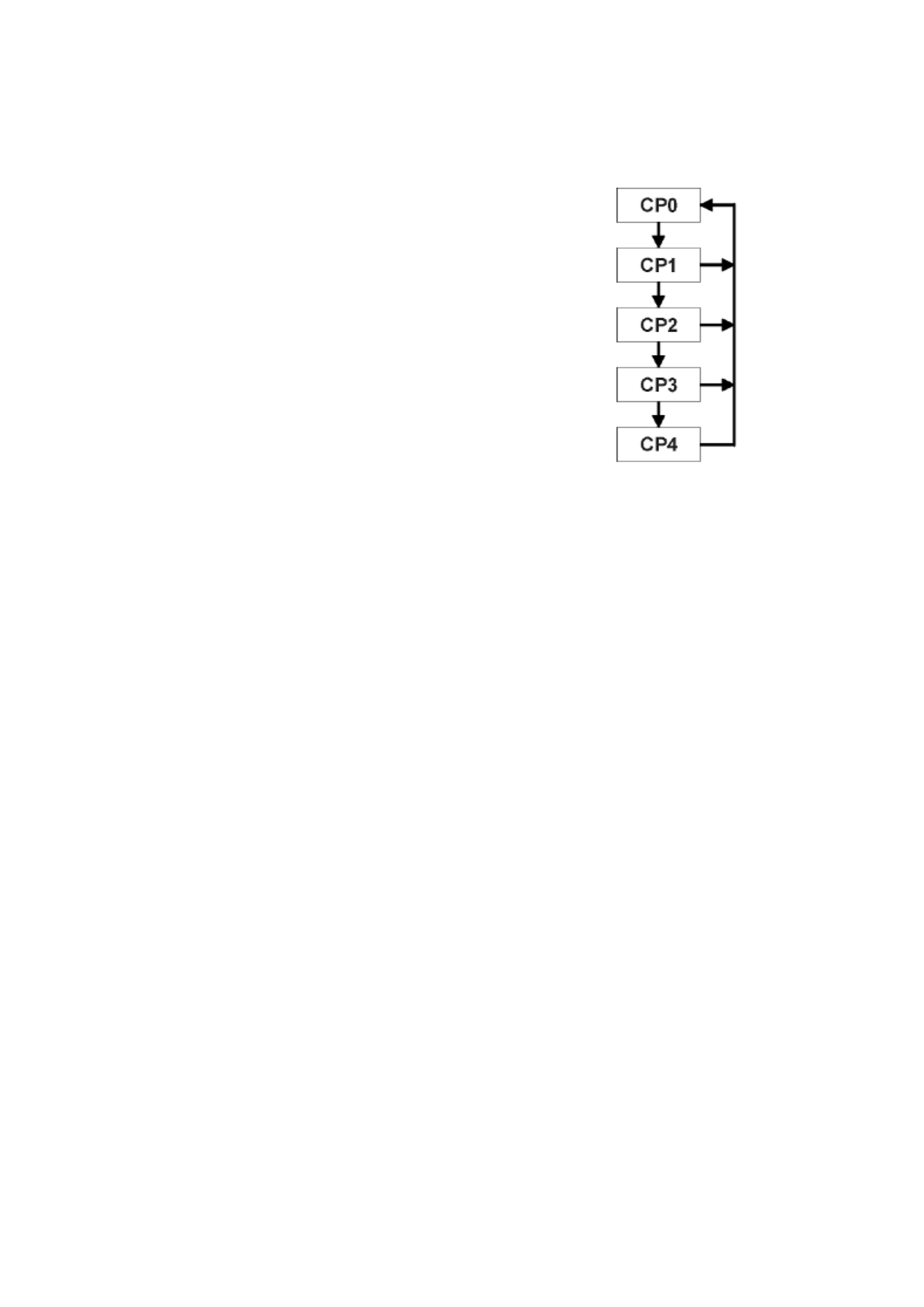
5.6 Initialisation (phase change)
To set up a SERCOS network, it is necessary to know the special
timing abilities of the connected drives in order to establish the
times for sending and receiving. In addition, the Master must
synchronise all slaves before the cyclical communication can
begin. For that, five phases are defined.
On the right side, the status diagram of SERCOS is depicted.
Normally, the next phase can only be reached through the
previous phase. Only Phase 0 can be reached from all phases,
in order to start a new initialization.
The Master determines the respective phase in the Master
synchronisation telegram (MST). To reach Phase 3 and Phase 4,
a procedure command must also be performed (see also
chapter 13.3).
Fig. 5.4: Phase change
5.6.1 Communication Phase 0: Closing the ring
In Phase 0, the Master tries to receive its own test signal to find out whether the SERCOS
ring is closed. All SERCOS slaves simply repeat the Master signal, so the Master can
recognise that the ring is closed. In case of a communication error, the slave can fall back
into Phase 0 by itself.
5.6.2 Communication Phase 1: Identification of the drives
Communication Phase 1 is used for recognising the drives connected to the ring. To do
this, the Master specially contacts each drive with its gear address to confirm that all
drives are present.
5.6.3 Communication P se 2: Loading the communication ha
parameters
In Communication Phase 2, the complete function of the service channel is available, and
non-cyclical data can be exchanged.
At a minimum, the following parameters must be transmitted:
1. Sending times and time slots
2. Parameters for specification of the content and length of the AT
3. Parameters for specification of the content and length of the MDT
Before the Master can change the phase in the MST to Communication Phase 3, the drive
must check the timing parameters sent by the Master. For that, a procedure command
must be carried out by the Master before it is permitted to switch to Phase 3. This
procedure command is called Communication phase 3 transition check (S-0- ). It is 0127
described in chapter 13.3. At a minimum, the parameters in the IDN list of operation data
for Communication Phase 2 (S-0-0018) must be transmitted without error in
Communication Phase 2.

5 Overview .
P.BE-CMMP-AS- - - 0708NH SC SW EN 31
For checking the validity of the parameters, the slave can only refer to general criteria
(e.g. minimum, maximum). The slave cannot recognise whether all parameters sent by the
Master regarding control data and the overall installation are correct. This means that,
even if the drive positively ‘confirms 'Preparation to Switch to Phase 3', incorrect
communication parameters may be present with regard to the overall installation, which
can result in interruption of cyclical communication.
Switching to Communication Phase 3 starts synchronisation of the drive with the
MST cycle.
5.6.4 Communication P se 3: Loading the communication ha
parameters
In Communication Phase 3, data exchange takes place over the telegrams defined for cycle
operation. The time slots for cycle operation are also used. The cycle operation data are
not relevant, that is, they are not used by the drive. But the telegram design must already
correspond to that of Communication Phase 4. In this phase, the drive can be adapted to
the specific application, e.g. by changing the scaling parameters for position, velocityand
acceleration.
To switch to Communication Phase 4, the drive must check the validity of the transmitted
parameters and also check whether it is synchronised. For that, a procedure command
must be carried out by the Master before it is permitted to switch to Phase 4.
This procedure command is called Communication Phase 4 transition check (S-0-0128).
It is described in chapter 13.3. At a minimum, the parameters in the IDN list of operation
data for Communication Phase 3 (S-0-0019) must be transmitted without error in
Communication Phase 3.
5.6.5 Communication Phase 4: Cycle operation
In this phase, initialisation is ended and cyclical data are exchanged. Now, power
connection of the drive is possible using the control word embedded in the MDT.
The drive status is displayed through the status word embedded in the AT.

6 SERCOS cycletime .
32 P.BE-CMMP- - - - 0708NH AS SC SW EN
6. SERCOS cycletime
Normally, the SERCOS cycletime can be determined by the parameter IDN S-0-0002 .
To achieve the best behaviour, all controllers within the CMMP- -SC (current controller, AS
velocitycontroller and position controller) must be synchronised with the MST.
Name
Factor
Cycle time
ti (current controller)
2
125 µs
tn (speed controller)
2
250 µs
tx (position controller)
2
500 µs
tp (interpolation calculation IPO) –
2
1000 µs
Tab. 6.1: SERCOS cycletime
7 Operation modes .
P.BE-CMMP-AS- - - 0708NH SC SW EN 33
7. Operation modes
The operation mode of the drive is determined by the control word in the MDT (see
chapter 9). You can choose between a primary operation mode and three secondary
operation modes. The respective operation mode can be read off using the status word.
The meaning of the primary and secondary operation modes must be determined by the
Master in Communication Phase 3. For this, the following IDNs must be used:
S-0-0032 Primary operation mode
S-0-0033 Secondary operation mode 1
S-0-0034 Secondary operation mode 2
S-0-0035 Secondary operation mode 3
The following values are permitted:
Values
Description
0x0000
Operation mode not defined
0x0001
Torque control
0x0002
Velocity control
0x000B
Position control using the "commutation encoder", drag-free, interpolation
0x000C
Position control using the "position feedback value encoder", drag-free, interpolation
0x002B
Drive-controlled interpolation using the "commutation encoder"
Tab. 7.1: Values
To choose between operation modes, you must have command values in the MDT for each
operation mode used.
The Master must ensure that command values in the MDT are
available for each operation mode use d.
Otherwise, the command value can be indefined when switching
into another operation mode, which can result in uncontrolled
behaviour of the drive.
As specified above, the change of operation mode is initiated by writing in the control
word. Since the change of operation mode takes some time, the momentary operation
mode can be read off using the status word. During the change to the new operation
mode, the command values for both operation modes must be valid. When the drive
signals the new operation mode in the status word, the command values for the old
operation mode no longer need to be valid.
The change into a non-initialised operation mode results in an error (37-5), which is
reported in the interface status (S-0-0014). See chapter 13.19.7.

7 Operation modes .
34 P.BE-CMMP- - - - 0708NH AS SC SW EN
7.1 Torque control
In the 'Torque control ' operation mode, a new command value (Torque command value
S-0-0080) must be available in the time grid of the SERCOS cycle time. This value is the
input value for the torque controller. The actual torque can be read off using the torque
feedback value (S-0-0084). It is the user's responsibility to ensure that the torque
command value is embedded in the MDT before switching into this operation mode.
7.2 Velocity control
In the 'Velocity control ' operation mode, a new command value (Velocity command value
S-0-0036) must be available in the time grid of the SERCOS cycletime. This value is the
input value for the torque controller, which generates the command value for the torque
controller. The actual velocitycan be read off using the Velocity feedback value 1
(S-0-0040). It is the user's responsibility to ensure that the velocity command value is
embedded in the MDT before switching into this operation mode.
7.3 Position control
In the 'Position control ' operation mode, a new command value (Position command value
S-0-0047) must be available in the time grid of the SERCOS cycletime. This value is the
input value for the internal interpolator. The interpolator creates position command values
in the time grid of the velocitycontroller (for example, four times faster than the SERCOS
cycle time) and also feed forward velocityvalues. Here, the position and velocitycontroller
receive new command values with a higher cycle time than the SERCOS cycle time.
Therefore, the drive follows the SERCOS position command values (command values)
drag-free (without lag error). The actual position can be read off either via the Position
feedback value 1 (S-0-0051) or Position feedback value 2 (S-0-0053). The first returns the
actual position value of the motor encoder, the second the feedback value of an optional
external encoder. They are alternately valid when the operation mode involved is active.
Otherwise, the feedback value 0 is returned. Switching back and forth online between the
internal and external feedback value is not permitted. When one operation mode IDN
(S-0-0032, S-0-0033, S-0-0034, S-0-0035) has been set to 0x000B, it is not allowed to set
another one to 0x000C, and vice versa. It is the user's responsibility to ensure that the
position command value is embedded in the MDT before switching into this operation
mode.
7.4 Drive-internal interpolation
In this operation mode, the drive receives a new target position from the Master and
moves on its own to this position while maintaining the specified positioning speed
(S-0-0259), positioning acceleration (S-0-0260) and positioning deceleration (S-0-0359).
The target position does not have to be cyclically specified; it can also be sent via the
service channel. A new positioning movement begins each time a new target position
(S-0-0258) is written.
8 Scaling of data .
P.BE-CMMP-AS- - - 0708NH SC SW EN 35
8. Scaling of data
Operating data can have different scalings in order to adapt the drives to the application.
SERCOS differentiates between unweighted operating data and application-specific,
weighted data.
In application-specific scaling, reference is made to the data in dependence on rotatory or
translatory load movements.
Several predefined scalings are available for position, speed, torque and acceleration data.
8.1 Position data
8.1.1 Overview
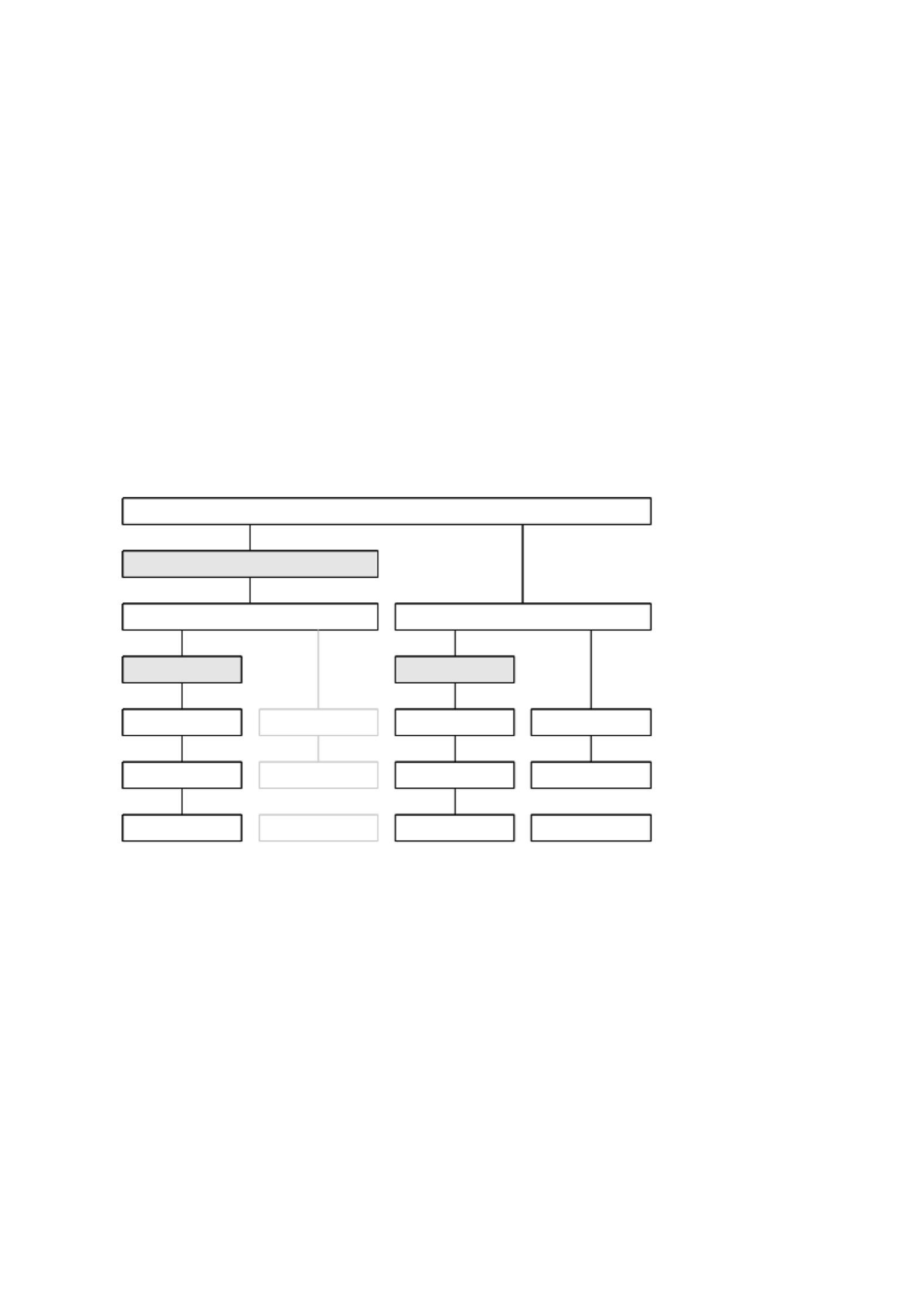
The scaling can be set bit for bit in IDN S-0-0076. The following diagram gives an overview
of the available scalings (the translatory scaling on the motor shaft has not yet been
available):
Position data scaling type S-0-0076
S-0-0123
S-0-0121 / 122
S-0-0076, Bit 0...2
S-0-0076, Bit 5
= 1 Bit
S-0-0076, Bit 6
Rotational
feed constant
Linear
Motor
meter
Motor
degree
Load
Gear ratio
meter
0,1 µm 0,0001 ° 0,0001 °
0,1 µm
Gear ratio
degree
Load
Fig. 8.1: Scaling of the position data

8 Scaling of data .
36 P.BE-CMMP- - - - 0708NH AS SC SW EN
The following values apply for IDN S-0-0076:
BIT
Description
Value
0 2 ...
Scaling type
00b: Unscaled (incremental)
01b: Translatory scaling
01b: Rotatory scaling
3
Preference scaling
0b: Preference scaling
1b: Not permitted
4
Unit for translatory/
rotatory scaling
0b: Metre/angle degree
1b: Not permitted
5
Reserved
6
Data reference
0b: On the motor shaft
1b: On the load
7
Processing format
0b: Absolute format
1b: Modulo format (see IDN S-0-0103)
8 ... 15
Reserved
Tab. 8.1: Values apply for IDN S-0-0076
8.1.2 Unscaled
If no scaling is chosen, all position data are sent with the internal scaling of the position
data (232 steps = 1 revolution). Since the position date defined by SERCOS are 4-byte
values, this scaling does not make sense in general for applications. For that reason,
"Unweighted" cannot be selected.
8.1.3 Translatory scaling
If a linear motor or linear drive is used, it is practical to use linear position values. The
scaling by the translatory position data scaling factor (S-0-0077) and by the translatory
position data scaling exponent (S-0-0078) is thereby defined using the following formula:
LSB = S-0-0077 * 10 S-0-0078
With 1 for the factor and -7 for the exponent, this results in a resolution of 0.1 µm per bit.
The ratio between revolutions of the motor and translatory movement is determined by the
feed constant (S-0-0123 If the translatory scaling is also applied to the load, the gear ).
transmission ratio (S-0-0121 -0-0122) must be set accordingly. /S
8.1.4 Rotatory scaling
If rotatory is selected, the rotational position resolution is specified by the parameter
S-0-0079, which defines the steps per revolutions.
A rotation position resolution of 3 600 000 results in a scaling of 0.0001° per bit.
If the rotatory scaling is also applied to the load, the gear transmission ratio
(S-0-0121 -0-0122) must be set accordingly. /S
8 Scaling of data .
P.BE-CMMP-AS- - - 0708NH SC SW EN 37
8.2 Velocity data
8.2.1 Overview
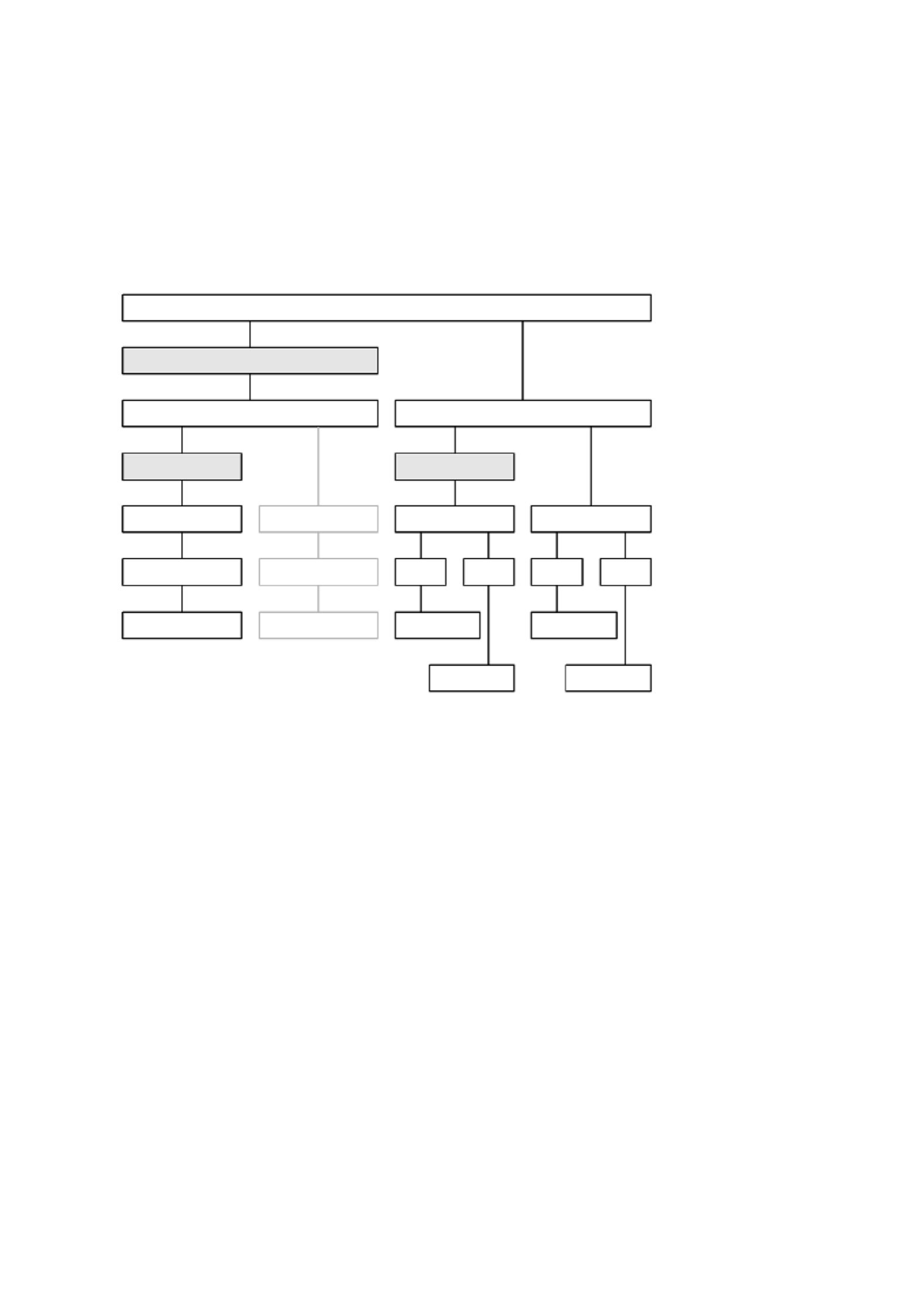
The scaling can be set bit for bit in IDN S-0-0044. The following diagram gives an overview
of the available scalings (the translatory scaling on the motor shaft has not yet been
available):
10 m / min
-6 10 m / min
-6 10 min
-4 -1 10 min
-4 -1
10-6 -1
s 10 s
-6 -1
min min
Velocity data scaling type S-0-0044
S-0-0123
S-0-0121 / 122
S-0-0044, Bit 0...2
S-0-0044, Bit 5
= 1 Bit
= 1 Bit
S-0-0044, Bit 6
Rotational
feed constant
Linear
Motor MotorLoad
Gear ratio Gear ratio
min mins s
Load
Fig. 8.2: Scaling of the velocity data

8 Scaling of data .
38 P.BE-CMMP- - - - 0708NH AS SC SW EN
The following values apply for IDN S-0-0044:
Bit
Description
Value
0 2 ...
Scaling type
00b: Unscaled (incremental)
01b: Translatory scaling
01b: Rotatory scaling
3
Preference scaling
0b: Preference scaling
1b: Not permitted
4
Unit for translatory/rotatory scaling
0b: Metres/revolutions
1b: Not permitted
5
Time units
0b: Minutes
1b: Seconds
6
Data reference
0b: On the motor shaft
1b: On the load
7 ... 15
Reserved
Tab. 8.2: Values apply for IDN S-0-0044
8.2.2 Unscaled
"Unscaled" has not been selectable.
8.2.3 Translatory scaling
For the translatory scaling of the velocity data, the scaling is defined by the Velocity data
scaling factor (S-0-0045) and the Velocity data scaling exponent (S-0-0046) using the
following formula:
LSB = S-0- * 10 0045 S-0-0046
With 1 for the factor and -6 for the exponent, this results in a resolution of 0.001 mm/min
per bit.
The ratio between revolutions of the motor shaft and translatory movement is determined
by the feed constant (S-0-0123 Since only scaling with a load reference can be selected, ).
the gear transmission ratio (S-0-0121 -0-0122) must be set accordingly. /S
8.2.4 Rotatory scaling
For the rotatory scaling of the velocity, the scaling is likewise defined by the Velocity data
scaling factor (S-0-0045) and the Velocity data scaling exponent (S-0-0046) using the
following formula:
LSB = S-0-0045 * 10 S-0-0046
For rotatory scaling, the time unit (min/s) can also be selected. For minutes, the scaling
exponent is -4, for seconds -6. With 1 for the factor, this results in a resolution of
0.0001 min-1 per bit or 0.000 001 s-1 per bit.
If the scaling is also applied to the load, the gear transmission ratio (S-0-0121/S-0-0122)
must be set accordingly.
8 Scaling of data .
P.BE-CMMP-AS- - - 0708NH SC SW EN 39
8.3 Acceleration data
8.3.1 Overview
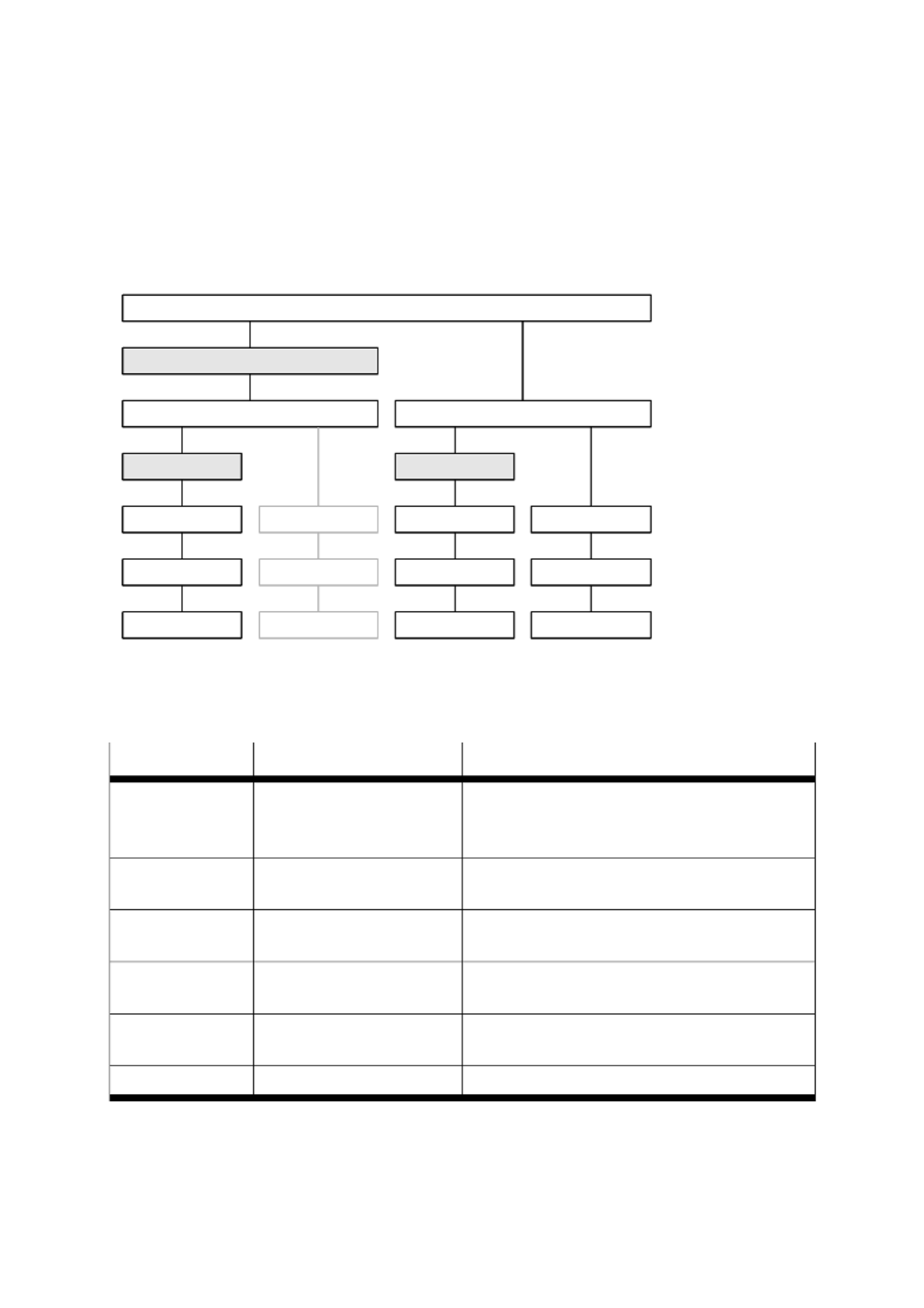
The scaling can be set bit for bit in IDN S-0-0160. The following diagram gives an overview
of the available scalings (the translatory scaling on the motor shaft has not yet been
available):
10 m / s
-6 2 10 rad / s
-3 2 10 rad / s
-3 2
10 m / min
-6 -1
s2s2s2s2
Acceleration data scaling type S-0-0160
S-0-0123
S-0-0121 / 122
S-0-0160, Bit 0...2
S-0-0160, Bit 5
= 1 Bit
S-0-0160, Bit 6
Rotational
feed constant
Linear
Motor MotorLoad
Gear ratio Gear ratio
Load
Fig. 8.3: Scaling of the acceleration data
The following values apply for IDN S-0-0160:
Bit
Description
Value
0 2 ...
Scaling type
00b: Unscaled (incremental)
01b: Translatory scaling
01b: Rotatory scaling
3
Preference scaling
0b: Preference scaling
1b: Not permitted
4
Unit for translatory/
rotatory scaling
0b: Metre/radians
1b: Not permitted
5
Time units
0b: Minutes
1b: Reserved
6
Data reference
0b: On the motor shaft
1b: On the load
7 ... 15
Reserved
Tab. 8.3: Values apply for IDN S-0-0160

8 Scaling of data .
40 P.BE-CMMP- - - - 0708NH AS SC SW EN
8.3.2 Unscaled
"Unscaled" has not been selectable.
8.3.3 Translatory scaling
For the translatory scaling of the acceleration data, the scaling is defined by the
Acceleration data scaling factor (S-0-0161) and the Acceleration data scaling exponent
(S-0-0162) using the following formula:
LSB = S-0-0161 * 10 S-0-0162
With 1 for the factor and -6 for the exponent, this results in a resolution of 0.000 001 m/s 2
per bit. The ratio between revolutions of the motor and translatory movement is
determined by the feed constant (S-0-0123). Since only scaling with a load reference can
be selected, the gear transmission ratio (S-0-0121 -0-0122) must be set accordingly. /S
8.3.4 Rotatory scaling
For the rotatory scaling of the acceleration, the scaling is likewise defined by the
Acceleration data scaling factor (S-0-0161) and the Acceleration data scaling exponent
(S-0-0162) using the following formula:
LSB = S-0-0161 * 10 S-0-0162
With 1 for the factor and -3 for the exponent, this results in a resolution of 0.001 rad/s 2
per bit. If the scaling is also applied to the load, the gear transmission ratio
(S-0-0121 -0-0122) must be set accordingly. /S
8.4 Torque data
Torque data are always specified in NM with regard to the motor. Since torque data are
weighted in NM, the torque constant (P-0-0100) is set accordingly.
8.5 Temperature data
Temperature data can be selected in °C and F through the Temperature data scaling type
(S-0-0208). Therefore, the following values apply for IDN S-0-0208:
Bit
Description
Value
0
Temperature unit
00b: 0.1 °C
01b: 0.1 F
1 ... 15
Reserved
Tab. 8.4: Temperature data

9 Control word/status word .
P.BE-CMMP-AS- - - 0708NH SC SW EN 41
9. Control word/status word
The drive can be controlled with the control word (sent in the MDT), and the status of the
drive can be read in the status word (sent in the AT).
In addition, some handshake bits for the service channel communication are embedded;
the operation mode can be selected (bit 8 ... 9); and the drive can be activated/deactivated
by the control word (bit 13 ... 15). Two configurable bits (realtime bits) can control
processes within the servo (see chapter 13.8). For debug purposes, the control word and
the status word can be read from "normal" IDNs: S-0-0134 d S-0-0135. an
Bit
Description
Value
0 2 ...
Service channel
Transport handshake of the service channel
3 5 ...
Data block element
000b: Service channel not active
001b: IDN
010b: Name
011b: Attribute
100b: Unit
101b: Minimum
110b: Maximum
111b: Operating data
6
Real-time control bit 1
7
Real-time control bit 2
8 9 …
Operation mode
00b: Primary operation mode
01b: Secondary operation mode 1
10b: Secondary operation mode 2
11b: Secondary operation mode 3
10 12 ...
Reserved
1 -> 0: If the drive performs a drive controlled homing the drive
is stopped with the homing acceleration. The homing is
not interrupted. It can be continued through a new setting
of the stop bit. In other cases, the stop bit is without effect!
0 -> 1: Continue the uninterrupted homing procedure.
13
Stop/new start
1 -> 0: The power stage is switched off immediately; the motor can
turn freely (if there is no motor brake).
The power stage is activated. The controller can be switched 1:
on by setting Bit 15.
14
Activate drive
(power stage)
1 -> 0: The motor is braked corresponding to the "quick-stop
parameter/ safety deceleration‚ (ServoCommander™:
parameter/deceleration quick stop). After braking, the –
power stage is switched off.
0 -> 1: If bit 14 is set, the power stage is activated and the motor is
controlled according to the actual baud rate.
15
Drive on
Tab. 9.1: Control word/status word
9 Control word/status word .
42 P.BE-CMMP- - - - 0708NH AS SC SW EN
Power stage deactivated
This means that the transistors are no longer actuated. If this con-
dition occurs with a rotating motor, it runs in idle without braking if
no mechanical brake is present. A motor brake is locked without
delay.
Careful: This does not ensure that current is shut off to the motor.
Power stage activated
This means that the motor is controlled according to the chosen
operation mode. If a motor brake is present, it is triggered. An
incorrect parameter setting or a defect can result in uncontrolled
behaviour by the motor.
Before switching on the power stage for the first time, make sure
that the servo controller contains the appropriate parameters for
the desired application (operation mode, telegram type, motor
current, etc.).
An incorrect parameter setting can cause uncontrolled behaviour
by the drive and thus result in personal injury and property
damage.
Check S-0-0092 (Bipolar torque limit value) before you activate the
drive.
If S-0-0092 is not set to a suitable value in Communication Phase 2,
no torque is placed on the motor. As a result, the motor will not
move.
The following bits of the status word can be read off. Like the real-time control bits, two
status bits (bit 6 and 7) can be configured in an application-specific way.
Bit
Descripti on
Value
0 … 5
Service channel
Transport handshake of the service channel
6
Realtime status bit 1
7
Realtime status bit 2
8 9 ...
Actual operation mode
00b: Primary operation mode
01b: Secondary operation mode 1
10b: Secondary operation mode 2
11b: Secondary operation mode 3
11
Change bit C3D
0b: Not changed
1b: Changed
12
Change bit C2D
0b: Not changed
1b: Changed
13
Change bit Condition
class 1
0b: No shut-down
1b: Shut-down due to error in condition class 1

9 Control word/status word .
P.BE-CMMP-AS- - - 0708NH SC SW EN 43
Bit
Descripti on
Value
14 … 15
Ready for operation
00b: Drive not ready for switching on
01b: Drive ready for switching on the power supply
10b: Drive ready and power supply on
11b: Drive ready for operation, power stage is active
Tab. 9.2: Status word
Linear axes must normally identify their initial position each time the drive is activated for
the first time. The identification process begins with a rising edge from bit 15 of the control
word and can take some time. Only when the identification process has been successfully
ended are bits 14 and 15 of the status word reduced to 11 b. To avoid timeouts in the
Master, the necessity of this identification procedure can be checked by reading off
S-0-0182.

10. Error management
44 P.BE-CMMP- - - - 0708NH AS SC SW EN
10. Error management
The servo controllers of the series CMMP-AS offer the possibility to change the error
reaction of individual events, e.g. the occurence of a lag error. As a result, the controller
reacts differently when a certain event occurs. Depending on the settings from
Error_management: Error_reaction (P-0-0041), if the drive can be braked, the power stage
is immediately deactivated or a warning message is shown on the display.
For each event, a manufacturer-specific minimal error reaction is defined, which cannot be
fallen below. In this way, "critical" faults, such as 06 0 short-circuit, might not be
parameterised , since immediate deactivation is necessary to protect the servo controller
from damage.
If an error reaction is set to a reaction that falls below the minimum permissible reaction
for this error, it is automatically set to the minimum permissible error reaction.
To change the error reaction, the parameter Error_Management: Error_ number (P-0-0040)
must be set. A list with all error codes can be found in the manual "Servo positioning
controller CMMP-AS".
The following parameters are possible for P-0-0041:
Value
Meaning
0
No action
1
Entry in the buffer
3
Warning on the 7-segment display
5
Deactivate controller
7
Braking with maximum current
8
Power stage deactivated
Tab. .1: P-0-0041 10

11. I/O functions
P.BE-CMMP-AS- - - 0708NH SC SW EN 45
11. I/O functions
The servo controller CMMP-AS permits the user access to all digital inputs (DIN) via an IDN
of the SERCOS interface. For that reason, the status of the DINs in P-0-0125 is read off
while the polarity of the DIN can be changed with P-0-0126.
Since some DINs are logical inputs displayed by status bits in the CMMP-AS, you can
assign variable hardware DINs. For example, the "measurement probe" (logical status)
hardware DIN8 of DIN9 is assigned. All others DINs, except for the "measurement probe",
"start input", "Reference switch" and the "Limit switches" are hardware DINs, which
directly show the voltage level on the corresponding pin.
For this reason, only the polarity of the "reference switch" and the "Limit switch" in
P-0-0126 are changed.
In addition, the digital outputs can be modified by writing in P-0-0110, whereby it is
possible to assign several status bits of a digital output, that is, when the status bit is set,
the outcome is likewise set. The arrangement can be made in P-0-0113 for DOUT1,
P-0-0114 for DOUT2 and P-0-0115 for DOUT3.
The following status bits are available:
Value
Description
Value
Description
0
DOUTx through P-0-0110 direct modification
9
Undervoltage intermediate circuit
1
Position XACT = XDEST
10
Enable brake
2
Position XACT = XDEST
11
Power stage enabled
3
Reserved
12
No function (ON)
4
Trigger remaining distance
13
Reserved
5
Homing procedure active
14
Reserved
6
Target velocity reached
15
Linear motor identified
7
I²t-limit active
16
Homing position valid
8
Lag error
Tab. .1: Status bits 11
12. Special commands
46 P.BE-CMMP- - - - 0708NH AS SC SW EN
12. Special commands
12.1 Drive-controlled homing
If the Master sets and activates the procedure command Drive controlled homing
(S-0-0148), the drive automatically activates the drive-internal position control and
accelerates the Homing velocity (S-0-0041), taking into account the Homing parameter
(S-0-0147) and the Homing acceleration (IDN S-0-0042). In addition, the drive resets the
Position feedback value status (S-0-0403) bit. All changes of the cyclical command values
are ignored as long as the procedure command is activated. After recognition of the
reference impulse, the drive brakes to stop, taking into account the homing acceleration.
The procedure command Drive controlled homing is successfully completed when the drive
is stopped and the Position command value (S-0-0047) is set to the machine's reference
point. The drive specifies this by setting the Position feedback value status (S-0-0403) bit.
After that, the controller must read the drive's position command value via the service
channel and reset its position command value system to this position command value.
After the procedure command has been reset through the controller, the drive again
follows the command values of the controller.
An interruption of this procedure command results in the actual position value not being
homed to the reference mark. The actual position value status bit is not set.
If an error of condition class 1 occurs, the procedure command is cancelled with an error.
Two parameters are considered in calculating the reference point:
Reference 1 (S-0-0052) and Reference offset 1 (S-0-0150). The Reference offset 1
determines the distance between the reference mark (e.g. the falling edge of the reference
switch) and reference point. The Reference 1 determines the position (in the coordinate
system after the homing procedure) at this point. It is normally 0.
The following illustration provides an overview of the reference point.
Reference pointDrive zero point
Reference distance
Reference offset
Homing switch
Fig. .1: Reference point 12

12. Special commands
P.BE-CMMP-AS- - - 0708NH SC SW EN 47
For details regarding the homing procedure, please consult the "Servo Positioning
Controller CMMP-AS" software manual.
The following options are possible for the Homing parameter (S-0-0147):
Bit
Description
Value
0
Homing direction
0b: Positive direction
1b: Negative direction
1
Reserved
2
Homing switch
0b: Not permitted/available
1b: Connected to the drive
3
Feedback
0b: Use of motor feedback
1b: Use of external feedback
4
Reserved
5
Evaluation of the homing switch
0b: Reference switch is evaluated
1b: Not permitted/available
6
Evaluation of actual position marker impulse
0b: Not permitted/available
1b: Marker impulse is not evaluated
7
Position after drive controlled homing
0b: Drive is in any position
1b: Not permitted/available
8
Drive controlled homing with homing distance
0b: Not permitted/available
1b: Homing distance is not selected
9 ... 15
Reserved
Tab. .1: Options 12
In contrast to the SERCOS specification, there is no reference offset for external feedback
values. IDN S-0-0150 (Reference offset 1) is used in both cases (internal and external
position feedback evaluation) to define the reference offset for the procedure command
Drive controlled homing.
The drive controlled homing procedure can only be performed in a
position control operation mode.
To be compatible with the SERCOS standard, not all possible homing methods can be set
via the Homing parameter (S-0-0147). A manufacturer-specific IDN must therefore be
implemented: Homing method (P-0-0045). Both parameters are independent of each
other, so the last written IDN determines the homing behaviour.
The following options are possible for the Homing parameter (P-0-0047 ):

12. Special commands
48 P.BE-CMMP- - - - 0708NH AS SC SW EN
Value
Direction
Objective
Reference point for zero point
- 18
Positive
End stop
End stop
- 17
Negative
End stop
End stop
-2
Positive
End stop
Zero pulse
-1
Negative
End stop
Zero pulse
1
Negative
Limit switches
Zero pulse
2
Positive
Limit switches
Zero pulse
7
Positive
Homing switch
Zero pulse
11
Negative
Homing switch
Zero pulse
17
Negative
Limit switches
Limit switches
18
Positive
Limit switches
Limit switches
23
Positive
Homing switch
Homing switch
27
Negative
Homing switch
Homing switch
33
Negative
Zero pulse
Zero pulse
34
Positive
Zero pulse
Zero pulse
35
-
Actual position
Tab. .2: Options 12
12.2 Spindle positioning
The Position spindle procedure command (S-0-0152) is used to position a motor at an
absolute angle position or rotate it to a relative offset.
When setting and activating the command, the drive starts to move into the desired
position, which was specified by the Spindle angle position (S-0-0153) or through the
relative offset (S-0-0180 ).
The IDN S-0-0154 (Spindle positioning parameter) determines the direction and command
value for positioning.
Until the command is activated, every command value written in S-0-0153 or S-0-0180
causes the drive to immediately start a new positioning. The maximum spindle positioning
speed (S-0-0222) is used for positioning.
If the interpolator of the drive reaches the selected command value, the drive sets the
Status "In position" (S-0-0336 ).
If the control unit cancels this command, the drive switches into operation mode set in the
control word. It is the user's responsibility to ensure that the command values at this time
are correct.
The following values can be used for IDN S-0-0154 (Spindle positioning parameter):

12. Special commands
P.BE-CMMP-AS- - - 0708NH SC SW EN 49
Bit
Description
Value
0 … 1
Direction
00b: Positive direction
01b: Negative direction
10b: Reserved
11b: Reserved
2
Type of positioning
0b: Absolute via spindle angle position (IDN S-0-0153)1
b:
Relative via relative offset (IDN S-0-0180)
3 … 15
Reserved
Tab. .3: IDN S-0-0154 12
All changes in this IDN become effective with the start of a new positioning. An already
active positioning is not influenced.
12.3 Probing (measurement)
Setting and activating the Probing cycle procedure command (S-0-0170) permits probing
of the position feedback values. The Probe control parameter (S-0-0169) can be used to
select whether the rising or falling edge is used. Probing is activated by Probe 1 enable
(S-0-0405).
When the selected edge appears at the digital input, the drive saves the position feedback
value in the parameters S-0-0130 to S-0-0133 and sets the related bit in the Probe status
(S-0-0179) and in Probe 1 positive latched (S-0-0409) or Probe 1 negative latched
(S-0-0410 ).
When an active edge appears, the operation is deactivated until Activate probe x is reset.
The measurement is reactivated with the following setting. See also chapter 13.15 and
13.9.
The following values can be used for IDN S-0-0169 (Probe control parameter):
Bit
Description
Value
0
Probe 1 positive edge
0b: Positive edge not active
1b: Positive edge active
1
Probe 1 negative edge
0b: Positive edge not active
1b: Positive edge active
Tab. .4: S-0-0169 12

12. Special commands
50 P.BE-CMMP- - - - 0708NH AS SC SW EN
12.4 Automatic motor identification
This function of the CMMP-AS servo controller allows the user to identify automatically the
correct settings for an unknown motor, such as the "number of pins", the "encoder offset
angle" and the current controller settings. For that reason, there are two procedure
commands for starting the automatic motor identification (P-0-0101 and P-0-0102). The
success of automatic motor identification can be read through P-0-0103.
Automatic motor identification is started by executing the corresponding command. If the
identification is successful, the command is ended normally; otherwise, the command is
ended with an error. In this case, reading of P-0-0103 provides information on the problem.
It is divided into two parts: Bit 0 ... 15 returns faults during the execution of P-0-0101, and
bit 16 … 31 returns faults during the execution of P-0-0102. Bit 0 or bit 16 are always set
when an error has occurred.
Error bits for P-0- Error bits for P-0- 0101 (0 … 15) 0102 (16 … 31)
Bit
Description
Bit
Description
0
Error in P-0-0101
16
Error in P-0-0102
1
Controller activates when starting
17
Controller activates when starting
2
Power stage deactivated during
execution
18
Power stage deactivated during
execution
3
Insufficient voltage level in the DC bus
19
Unknown angle encoder
4
Invalid control time pulse
20
Index pulse not found
5
Reserved
21
Invalid hall sensor signals
6
Reserved
22
Commutation to hall sensor not possible
7
Reserved
23
No segment change after 90°
8
Reserved
24
Invalid segment distance
9
Reserved
25
Motor could not rotate
10
Reserved
26
Invalid number of poles determined
11
Reserved
27
Reserved
12
Reserved
28
Reserved
13
Reserved
29
Reserved
14
Reserved
30
Reserved
15
Confirmed parameters are limited
31
Reserved
Tab. .5: Error bits 12
If the automatic identification function fails, please check the DC bus voltage, the encoder
connection and the status of DIN4: They must be set during the identification function.

12. Special commands
P.BE-CMMP-AS- - - 0708NH SC SW EN 51
D 4 must be set to activte the power stage for carrying out the IN
identification function.
Starting the automatic identification function causes the motor to
begin moving on its own! Therefore, the motor must be freely
rotating!

13. Parameters
52 P.BE-CMMP- - - - 0708NH AS SC SW EN
13. Parameters
13.1 Overview
A unique IDN is assigned to all data for reading and writing the information. The data type
can be read via the "attribute", which is available for every IDN. Besides "normal" signed
and unsigned data types, "text" and "IDN list" are also available. For detailed information
regarding the data types, please consult the SERCOS specification.
This chapter briefly describes all parameters that are implemented in the CMMP-AS series.
13.1.1 Communication parameters
IDN
Description
S-0-0001
NC cycletime (tNcyc)
S-0-0002
SERCOS cycletime (tScyc)
S-0-0003
Shortest AT transmission starting time (t1min)
S-0-0004
Transmit/receive transmission time (tATMT)
S-0-0005
Minimum feedback processing time (t5)
S-0-0006
AT transmission starting time (t 1)
S-0-0007
Feedback acquisition time (t4)
S-0-0008
Command value valid time (t3)
S-0-0009
Position of data record in MDT
S-0-0010
Length of master data telegram
S-0-0087
Transmission to transmission recovery time (tATAT)
S-0-0088
Receive to receive recovery time (tMTSY)
S-0-0089
MDT transmission starting time (t 2)
S-0-0090
Command value proceeding time (tMTSG)
S-0-0096
Slave arrangement (SLKN)
S-0-0127
CP3 transition check (CP = Communication Phase)
S-0-0128
CP4 transition check
S-0-0028
MST error counter
S-0-0029
MDT error counter
Tab. .1: Communication parameters 13

13. Parameters
P.BE-CMMP-AS- - - 0708NH SC SW EN 53
IDN
S-0-0001
Name
NC cycletime (tNcyc)
Description
The NC cycletime determines the cyclical time intervals in which the numeric control
makes available new new command values. The NC cycletime is transmitted from
Master to slave during Comm. Phase 2 and becomes active in Comm. Phase 3.
The NC cycletime must agree with the SERCOS cycletime tNcyc = tScyc
Bytes
2
Min.
S-0-0002
Max.
S-0-0002
Unit
1 µs
IDN
S-0-0002
Name
SERCOS cycletime (tScyc)
Description
The communication cycletime of the interface determines in which time intervals the
cyclical data are transmitted. The SERCOS cycletime is set at 500 µs, 1 ms and up to
10 ms in steps of 1 ms. The SERCOS cycletime is transmitted from Master to slave
during Comm. Phase 2 and becomes active in Comm. Phase 3 in both the Master and
the slave. See also chapter 6!
Bytes
2
Min.
500 (see also chapter 6)
Max.
10 000 (see also chapter 6)
Unit
1 µs
IDN
S-0-0003
Name
Shortest AT transmission starting time (t1min)
Description
Specifies the time requirement of the slaves between the end of the received Master
synchronisation telegram and transmission start of the axis telegram. This time interval,
required by the slave, depends on the telegram type selected. The time t1min is read by
the Master in Communication Phase 2 to calculate the transmission starting time of the
AT t1 (IDN S-0-0006).
Bytes
2
Min.
-
Max.
-
Unit
1 µs

13. Parameters
54 P.BE-CMMP- - - - 0708NH AS SC SW EN
IDN
S-0-0004
Name
Transmit/receive transmission time (tATMT)
Description
The time required by the slave to switch over to receiving the Master data telegram after
transmitting the axis telegram. The Transmit/receive transmission time is read by the
Master in Comm. Phase 2 to correctly calculate the transmission starting time of the
Master data telegram t2 (IDN S-0089).
Bytes
2
Min.
-
Max.
-
Unit
1 µs
IDN
S-0-0005
Name
Minimum feedback processing time (t5)
Description
Time requirement of a drive between the start of the feedback processing time and the
end of the next Master synchronisation telegram. This value is specified by the drive in
such a way that the feedback values are transmitted to the numeric control in the next
axis telegram. The Master reads this value in Communication Phase 2 to appropriately
synchronise the Feedback acquisition time t4 (IDN S-0-0007) for all drives.
Bytes
2
Min.
-
Max.
-
Unit
1 µs
IDN
S-0-0006
Name
AT transmission starting time (t1)
Description
The AT transmission starting time determines when the slave, after the end of the
Master synchronisation telegram, transmits its axis telegram in Communication Phase 3
and 4. This parameter is transmitted in Communication Phase 2 from the Master to the
slave. The AT transmission starting time must be set greater than or equal to the
Shortest AT transmission starting time (IDN S-0-0003). t1 = t1min.
Bytes
2
Min.
t1min (S-0-0003)
Max.
tScyc (S-0-0002)
Unit
1 µs

13. Parameters
P.BE-CMMP-AS- - - 0708NH SC SW EN 55
IDN
S-0-0007
Name
Feedback acquisition time (t4)
Description
The Feedback acquisition time is set by the Master after the end of the Master
synchronisation telegram. Thus, the Master specifies a predetermined feedback
acquisition time for all drives that work together in a coordinated manner. This ensures
synchronisation of the feedback processing time. The feedback acquisition time cannot
be adjusted in the CMMP- -SC. It is implicitly determined by t3. AS
Bytes
2
Min.
0
Max.
tScyc (S-0-0002)
Unit
1 µs
IDN
S-0-0008
Name
Command value valid time (t3)
Description
T3 determines at which time the drive may access the new command values after
completion of a Master synchronisation telegram. The Master thus specifies the same
"Command value valid time" for all drives that work together in a coordinated manner.
The drive activates den "Command value valid time" in Communication Phase 3.
Bytes
2
Min.
0
Max.
tScyc (S-0-0002)
Unit
1 µs
IDN
S-0-0009
Name
Position of data record in MDT
Description
The position of data record of the drive in a Master data telegram, expressed as a byte
position. They start with 1 for the first data byte after the address field in the MDT.
The positon of the data record in the MDT is passed on by the Master to each drive in
Communication Phase 2. The position of a data record in Length of MDT, expressed in
bytes, contains data records for all drives. In Communication Phase 2, the Master
informs each drive about the length of the MDT. It becomes active in the Master and the
slave during Communication Phase 3.
Bytes
2
Min.
1
Max.
65531
Unit
--

13. Parameters
56 P.BE-CMMP- - - - 0708NH AS SC SW EN
IDN
S-0-0010
Name
Length of master data telegram
Description
The Length of the Master data telegram, expressed in bytes, contains data records for
all drives. In Communication Phase 2, the Master informs each drive about the length of
the MDT.
It becomes active in the Master and the slave during Communication Phase 3.
Bytes
2
Min.
4 (a drive)
Max.
65534
Unit
--
IDN
S-0-0087
Name
Transmission to transmission recovery time (tATAT)
Description
The time required between two axis telegrams if transmitted by the same slave.
This parameter is not used for slaves with a single drive.
Bytes
2
Min.
--
Max.
--
Unit
1 µs
IDN
S-0-0088
Name
Receive to receive recovery time (tMTSY)
Description
Recovery time of the slave after receiving a Master data telegram in order to switch over
to receive the next Master synchronisation telegram. The Master reads this time in
Communication Phase 2 to ensure that the interval between the end of the Master data
telegram and the start of the Master synchronisation telegram is sufficient.
Bytes
2
Min.
--
Max.
--
Unit
1 µs

13. Parameters
P.BE-CMMP-AS- - - 0708NH SC SW EN 57
IDN
S-0-0089
Name
MDT transmission starting time (t2)
Description
The MDT transmission starting time determines when the Master, after the Master
synchronisation telegram, transmits its Master data telegram in Communication Phase 3
and 4. This parameter is transmitted in Communication Phase 2 from the Master to the
slave and becomes active in Communication Phase 3.
Bytes
2
Min.
0
Max.
tSCYC (IDN S-0-0002)
Unit
1 µs
IDN
S-0-0090
Name
Command value proceeding time (tMTSG)
Description
The time required by the slave to provide the command values for a drive after receiving
a Master data telegram. This time is read by the Master in Comm. Phase 2 to correctly
calculate the "Command value valid time" t3 (IDN S-0-0008). The command value
proceeding time depends on the telegram type.
Bytes
2
Min.
--
Max.
--
Unit
1 µs
IDN
S-0-0028
Name
MST error counter
Description
The MST error counter counts all invalid Master synchronisation telegrams in the
Communication Phases 3 and 4. If more than two successive MSTs are invalid,
additional invalid MSTs are not counted.
The MST error counter counts up to a maximum of 216 - 1. This means, if a value of
65535 is set in the counter, a strongly disturbed transmission must have taken place for
a longer period of time.
Bytes
2
Min.
--
Max.
--
Unit
--

13. Parameters
58 P.BE-CMMP- - - - 0708NH AS SC SW EN
IDN
S-0-0029
Name
MDT error counter
Description
The MST error counter counts all invalid Master synchronisation telegrams in the
Communication Phases 3 and 4. If more than two successive MSTs are invalid,
additional invalid MSTs are not counted.
The MST error counter counts up to a maximum of 216 - 1. This means, if a value of
65535 is set in the counter, a strongly disturbed transmission must have taken place for
a longer period of time.
Bytes
2
Min.
--
Max.
--
Unit
--

13. Parameters
P.BE-CMMP-AS- - - 0708NH SC SW EN 59
13.2 Telegram configuration
IDN
Description
S-0-0015
Telegram type
S-0-0016
Configuration list AT
S-0-0024
Configuration list MDT
S-0-0185
Length of configurable data record in the AT
S-0-0186
Length of configurable data record in the MDT
S-0-0187
IDN list of all configurable data in the AT
S-0-0188
IDN list of all configurable data in the MDT
Tab. .2: Telegram configuration 13
IDN
S-0-0015
Name
Telegram type
Description
The parameter Telegram type permits selection between standard telegrams and
application telegrams (Bits 0 2). See also chapter 5.5. …
Bytes
2
Min.
00000000 00000000b
Max.
00000000 00000111b
Unit
--
IDN
S-0-0016
Name
Configuration list AT
Description
The IDN list contains the IDNs whose operating data are cyclically transmitted into an
application telegram in the axis telegram.
Permitted as cyclical data are only those listed in the "IDN list of all configurable data in
the AT" (IDN S-0-0187). See also chapter 5.5.2.
Bytes
IDN list
Min.
0 IDNs
Max.
4 IDNs
Unit
IDN list

13. Parameters
60 P.BE-CMMP- - - - 0708NH AS SC SW EN
IDN
S-0-0024
Name
Configuration list MDT
Description
The IDN list contains the IDNs whose operating data are cyclically transmitted into an
application telegram in the Master data telegram.
Permitted as cyclical data are only those listed in the "IDN list of all configurable data in
the MDT" (IDN S-0-0188 See also chapter 5.5.2. ).
Bytes
IDN list
Min.
0 IDNs
Max.
4 IDNs
Unit
IDN list
IDN
S-0-0185
Name
Length of configurable data record in the AT
Description
In the operating data of this IDN, the drive specifies the maximum length in bytes that it
can process in the configurable data record of the axis telegram.
With regard to performance, a maximum length of 64 bytes (4 * 32 bit variables) can be
transmitted via the axis telegram, but only a maximum of 4 IDNs can be configured in
the Configuration list AT (S-0-0016 ).
Bytes
2
Min.
-
Max.
-
Unit
1
IDN
S-0-0186
Name
Length of configurable data record in the MDT
Description
In the operating data of this IDN, the drive specifies the maximum length in bytes that it
can process in the configurable data record of the Master data telegram.
With regard to performance, a maximum length of 64 bytes (4 * 32 bit variables) can be
transmitted via the Master data telegram, but only a maximum of 4 IDNs can be
configured in the Configuration list MDT (S-0-0024 ).
Bytes
2
Min.
-
Max.
-
Unit
1

13. Parameters
P.BE-CMMP-AS- - - 0708NH SC SW EN 61
IDN
S-0-0187
Name
IDN list of all configurable data in the AT
Description
This list contains all IDNs of the operating data that can be cyclically processed by the
drive as feedback values in the axis telegram.
The user should only configure IDNs from this list as cyclical data for the axis telegram
in the "Configuration list AT" (S-0-0016 ).
Bytes
IDN list
Min.
-
Max.
-
Unit
IDN list
IDN
S-0-0188
Name
IDN list of all configurable data in the MDT
Description
This list contains all IDNs of the operating data that can be cyclically processed by the
drive as command values in the Master data telegram.
The user should only configure IDNs from this list as cyclical data for the Master data
telegram in the "Configuration list MDT" (S-0-0024 ).
Bytes
IDN list
Min.
-
Max.
-
Unit
IDN list

13. Parameters
62 P.BE-CMMP- - - - 0708NH AS SC SW EN
13.3 IDN lists/phase switching commands
IDN
Description
S-0-0017
IDN list of all operation data
S-0-0018
IDN list of operation data for CP2
S-0-0019
IDN list of operation data for CP3
S-0-0020
IDN list of operation data for CP4
S-0-0021
IDN list of invalid operation data for CP2
S-0-0022
IDN list of invalid operation data for CP3
S-0-0023
IDN list of invalid operation data for CP4
S-0-0025
IDN list of all commands
S-0-0127
CP3 transition check (procedure command)
S-0-0128
CP4 transition check (procedure command)
Tab. .3: Phase switching commands 13
IDN
S-0-0017
Name
IDN list of all operation data
Description
All IDNs of all operation data can be read in this IDN list
Bytes
IDN list
Min.
--
Max.
--
Unit
IDN list
IDN
S-0-0018
Name
IDN list of operation data for CP2
Description
In this IDN list are stored the IDNs of all operation data that are needed for
Communication Phase 2 and that must be transmitted during Communication Phase 2.
Error-free writing of all these IDNs is necessary before switching into Communication
Phase 3.
Bytes
IDN list
Min.
--
Max.
--
Unit
IDN list

13. Parameters
P.BE-CMMP-AS- - - 0708NH SC SW EN 63
IDN
S-0-0019
Name
IDN list of operation data for CP3
Description
In this IDN list are stored the IDNs of all operation data that are needed for
Communication Phase 3 and that must be transmitted during Communication Phase 3.
Error-free writing of all these IDNs is necessary before switching into Communication
Phase 4.
Bytes
IDN list
Min.
--
Max.
--
Unit
IDN list
IDN
S-0-0020
Name
IDN list of operation data for CP4
Description
In this IDN list are stored all operation data that can be changed during Communication
Phase 4.
Bytes
IDN list
Min.
--
Max.
--
Unit
IDN list
IDN
S-0-0021
Name
IDN list of invalid operation data for CP2
Description
In this IDN list are stored the IDNs found in the "IDN list of operation data for CP 2"
(IDN S-0-0018) and considered invalid by the drive before switching from
Communication Phase 2 to Communication Phase 3 (see IDN S-0-0127 ).
Case 1: Command IDN S-0-0127 is correctly executed; the IDN list (IDN S-0-0021)
contains no IDNs.
Case 2: Command IDN S-0-0127 is correctly executed; the IDN list (IDN S-0-0021)
contains all IDNs of invalid operation data.
Bytes
IDN list
Min.
--
Max.
--
Unit
IDN list

13. Paramete rs
64 P.BE-CMMP- - - - 0708NH AS SC SW EN
IDN
S-0-0022
Name
IDN list of invalid operation data for CP3
Description
In this IDN list are stored the IDNs found in the "IDN list of operation data for CP 3"
(IDN S-0-0019) and considered invalid by the drive before switching from
Communication Phase 3 to Communication Phase 4 (see IDN S-0-0128 ).
Case 1: Command IDN S-0-0128 is correctly executed; the IDN list (IDN S-0-0021)
contains no IDNs.
Case 2: Command IDN S-0-0127 is correctly executed; the IDN list (IDN S-0-0021)
contains all IDNs of invalid operation data.
Bytes
IDN list
Min.
--
Max.
--
Unit
IDN list
IDN
S-0-0023
Name
IDN list of invalid operation data for CP4
Description
In this IDN list are stored the IDNs of all drive data that are considered invalid by the
drive after switching to Communication Phase 4.
Bytes
IDN list
Min.
--
Max.
--
Unit
IDN list
IDN
S-0-0025
Name
IDN list of all commands
Description
In this IDN list are stored the IDNs of all procedure commands supported by the drive.
Bytes
IDN list
Min.
--
Max.
--
Unit
IDN list

13. Parameters
P.BE-CMMP-AS- - - 0708NH SC SW EN 65
IDN
S-0-0127
Name
CP-3 transition check (procedure command)
Description
With this command, the Master tells the slave to check that all required parameters for
Communication Phase 3 have been transmitted. Otherwise, this command results in an
error (see IDN S-0-0021 ).
After correct execution of the command, the controller must interrupt the command.
The controller can then activate Communication Phase 3 in the Master synchronisation
telegram.
Bytes
2
Min.
-
Max.
-
Unit
-
IDN
S-0-0128
Name
CP-4 transition check (procedure command)
Description
With this command, the Master tells the slave to check that all required parameters for
Communication Phase 4 have been transmitted. Otherwise, this command results in an
error, (see IDN S-0-0022).
After correct execution of the command, the controller must interrupt the command.
The controller can then activate Communication Phase 4 in the Master synchronisation
telegram.
Bytes
2
Min.
-
Max.
-
Unit
-

13. Parameters
66 P.BE-CMMP- - - - 0708NH AS SC SW EN
13.4 Operation modes
IDN
Description
S-0-0032
Primary operation mode
S-0-0033
Secondary operation mode 1
S-0-0034
Secondary operation mode 2
S-0-0035
Secondary operation mode 3
Tab. .4: Operation modes 13
IDN
S-0-0032
Name
Primary operation mode
Description
The primary operation mode is defined in this IDN. The Master can switch the operation
mode by setting bits in the control word. See also chapter 7 and 9.
Bytes
Min.
Max.
Unit
IDN
S-0-0033
Name
Secondary operation mode 1
Description
The Secondary operation mode 1 is defined in this IDN. The Master can switch the
operation mode by setting bits in the control word. See also chapter 7 and 9.
Bytes
Min.
Max.
Unit
IDN
S-0-0034
Name
Secondary operation mode 2
Description
The Secondary operation mode 2 is defined in this IDN. The Master can switch the
operation mode by setting bits in the control word. See also chapter 7 and 9.
Bytes
Min.
Max.
Unit

13. Parameters
P.BE-CMMP-AS- - - 0708NH SC SW EN 67
IDN
S-0-0035
Name
Secondary operation mode 3
Description
The Secondary operation mode 3 is defined in this IDN. The Master can switch the
operation mode by setting bits in the control word. See also chapter 7 and 9.
Bytes
Min.
Max.
Unit
13.5 Scaling parameter
IDN
Description
S-0-0086
Scaling type for torque
S-0-0093
Torque scaling factor
S-0-0094
Torque scaling exponent
S-0-0044
Velocity data scaling type
S-0-0045
Velocity data scaling factor
S-0-0046
Velocity data scaling exponent
S-0-0076
Position data scaling type
S-0-0077
Position data scaling factor
S-0-0078
Position data scaling exponent
S-0-0079
Rotational position resolution
S-0-0103
Modulo value
S-0-0160
Acceleration scaling type
S-0-0161
Acceleration scaling factor
S-0-0162
Acceleration scaling exponent
S-0-0208
Temperature data scaling type
S-0-0121
Input revolutions of load gear
S-0-0122
Output revolutions of load gear
S-0-0123
Feed constant
Tab. .5: Scaling parameter 13

13. Parameters
68 P.BE-CMMP- - - - 0708NH AS SC SW EN
IDN
S-0-0086
Name
Torque scaling type
Description
In this stage of SERCOS implementation, only the rotatory scaling in Nm with reference
to the motor shaft is permitted for torque data. See also chapter 8.4.
Bytes
2
Min.
00000000 00000010b
Max.
00000000 00000010b
Unit
--
IDN
S-0-0093
Name
Torque scaling factor
Description
This parameter determines the scaling factor for all torque/power data in the drive.
It can only be read. See also chapter 8.4.
Bytes
2
Min.
1
Max.
+216 - 1
Unit
1
IDN
S-0-0094
Name
Torque scaling exponent
Description
This parameter determines the scaling exponent for all torque/power data in the drive.
It can only be read. See also chapter 8.4.
Bytes
2
Min.
-215
Max.
+215 - 1
Unit
1
IDN
S-0-0044
Name
Velocity data scaling type
Description
Various scaling types can be selected with the scaling type parameter. See also cha p.
8.2.
Bytes
4
Min.
00000000 00000000b
Max.
00000000 01110011b

13. Parameters
P.BE-CMMP-AS- - - 0708NH SC SW EN 69
Unit
--
IDN
S-0-0045
Name
Velocity data scaling factor
Description
This parameter determines the scaling factor for all velocity data. It can only be read.
See also chapter 8.2.
Bytes
2
Min.
1
Max.
+216 - 1
Unit
--
IDN
S-0-0046
Name
Velocity data scaling exponent
Description
This parameter determines the scaling exponent for all velocity data. It can only be read.
See also chapter 8.2.
Bytes
2
Min.
-215
Max.
+215 - 1
Unit
--
IDN
S-0-0076
Name
Position data scaling type
Description
Various scaling types for position data can be selected with this scaling type parameter.
See also chapter 8.1.
Bytes
2
Min.
See chapter 8.1.
Max.
See chapter 8.1.
Unit
--
IDN
S-0-0077
Name
Position data scaling factor
Description
This parameter determines the scaling factor for all position data in a drive. It can only
be read. See also chapter 8.1.
Bytes
2
Min.
1

13. Parameters
70 P.BE-CMMP- - - - 0708NH AS SC SW EN
Max.
+216 - 1
Unit
--
IDN
S-0-0078
Name
Position data scaling exponent
Description
This parameter determines the scaling exponent for all position data in a drive.
It can only be read. See also chapter 8.1.
Bytes
2
Min.
-215
Max.
+215 - 1
Unit
--
IDN
S-0-0079
Name
Rotational position resolution
Description
This parameter determines the rotational position resolution for all position data in a
drive. It can only be read. See also chapter 8.1.
Bytes
4
Min.
1
Max.
+232 - 1
Unit
--
IDN
S-0-0103
Name
Modulo value
Description
If bit 7 (modulo format) is set in S-0-0076, the position data are specified in the range
0 S-0-0103. The maximum difference between two consecutive position command …
values must not exceed IDN S-0-0103/2! See also chapter 8.1.
Bytes
4
Min.
0
Max.
+231 - 1
Unit
Corresponding to position data scaling type (IDN S-0-0076)
IDN
S-0-0160
Name
Acceleration scaling type
Description
Various scaling types can be selected with the acceleration scaling type parameter.
See chapter 8.3.

13. Parameters
P.BE-CMMP-AS- - - 0708NH SC SW EN 71
Bytes
2
Min.
See chapter 8.3.
Max.
See chapter 8.3.
Unit
--
IDN
S-0-0161
Name
Acceleration scaling factor
Description
This parameter determines the scaling factor for all position data in a drive.
It can only be read. See chapter 8.3.
Bytes
2
Min.
1
Max.
+216 - 1
Unit
1
IDN
S-0-0162
Name
Acceleration scaling exponent
Description
This parameter determines the scaling exponent for all position data in a drive.
It can only be read. See chapter 3. 8.
Bytes
2
Min.
-215
Max.
+215 - 1
Unit
1
IDN
S-0-0208
Name
Temperature data scaling type
Description
This scaling type parameter determines whether degrees Celsius [°C] or Fahrenheit [F]
are used as the unit for all temperature data in the drive. The data length of all
temperature data is set at two bytes. See chapter 8.5.
Bytes
2
Min.
00000000 00000000b
Max.
00000000 00000001b
Unit
--

13. Parameters
72 P.BE-CMMP- - - - 0708NH AS SC SW EN
IDN
S-0-0121
Name
Input revolutions of load gear
Description
When a scaling type with load reference is selected, the gear output format is calculated
with the conversion factors. The input revolutions must be entered as whole numbers in
this IDN.
Bytes
4
Min.
1
Max.
+232 - 1
Unit
1
IDN
S-0-0122
Name
Output revolutions of load ge ar
Description
When a scaling type with load reference is selected, the gear output format is calculated
with the conversion factors. The output revolutions must be entered as whole numbers
in this IDN.
Bytes
4
Min.
1
Max.
+232 - 1
Unit
1
IDN
S-0-0123
Name
Feed constant
Description
The feed constant describes the machine element that converts a rotatory movement
into a translatory one. The feed constant describes the linear section during a revolution
of the feed spindle. It is used for all translatory data scalings.
Bytes
4
Min.
1
Max.
+232 - 1
Unit
1 µm/revolution

13. Parameters
P.BE-CMMP-AS- - - 0708NH SC SW EN 73
13.6 Command/feedback values
IDN
Description
S-0-0047
Position command value
S-0-0051
Position feedback value 1
S-0-0053
Position feedback value 2
S-0-0036
Speed setpoint
S-0-0040
Velocity feedback value 1
S-0-0080
Torque command value
S-0-0083
Torque feedback value 1
Tab. .6: Command/feedback values 13
IDN
S-0-0047
Name
Position command value
Description
In the Position control operation mode, position command values from the numeric
control are transmitted to the drive according to the time grid of the NC cycle.
Bytes
4
Min.
-231
Max.
+231 - 1
Unit
Corresponding to position data scaling type (IDN S-0-0076)
IDN
S-0-0051
Name
Position feedback value 1 (motor feedback value)
Description
The position feedback value 1 is transmitted from the drive to the controller, so that the
controller can monitor and display the position information. The position feedback value
1 refers to the motor encoder
(ServoCommander™: operation mode/encoder selection/commutation encoder)
Important: If the Position feedback value 2 (external encoder) is selected,
the value of this IDN is 0.
Bytes
4
Min.
-231
Max.
+231 - 1
Unit
Corresponding to position data scaling type (IDN S-0-0076)

13. Parameters
74 P.BE-CMMP- - - - 0708NH AS SC SW EN
IDN
S-0-0053
Name
Position feedback value 2 (external encoder)
Description
Position feedback value 2 contains the position feedback value of an optional external
encoder.
Important: If the position control of Position feedback value 1 (motor encoder)
is selected as the operation mode, the value of this IDN is 0.
Bytes
4
Min.
-231
Max.
+231 - 1
Unit
Corresponding to position data scaling type (IDN S-0-0076)
IDN
S-0-0036
Name
Speed setpoint
Description
In the drive's velocity control operation mode, the controller transmits the velocity
command values to the drive in the time grid of the NC cycletime.
Bytes
4
Min.
--
Max.
--
Unit
Corresponding to the Velocity data scaling type (IDN S-0-0044)
IDN
S-0-0040
Name
Velocity feedback value 1
Description
The velocity feedback value 1 is transmitted from the drive to the controller so that the
controller can periodically display the velocity. The Velocity feedback value 1 always
refers to the motor encoder.
(ServoCommander™: operation mode/encoder selection/commutation encoder)
Bytes
4
Min.
--
Max.
--
Unit
Corresponding to the velocity data scaling type (IDN S-0-0044)
IDN
S-0-0080
Name
Torque command value

13. Parameters
P.BE-CMMP-AS- - - 0708NH SC SW EN 75
Description
In the drive's torque control operation mode, the controller transmits the torque
command values to the drive.
Bytes
2
Min.
-215
Max.
+215 - 1
Unit
Corresponding to Torque scaling type (IDN S-0-0086)
IDN
S-0-0084
Name
Torque feedback value
Description
The torque feedback value is transmitted from the drive to the controller in the torque
control operation mode.
Bytes
2
Min.
-215
Max.
+215 - 1
Unit
Corresponding to torque scaling type (IDN S-0-0086)
13.7 Limitation/monitoring
IDN
Description
S-0-0091
Bipolar velocity limit value
S-0-0092
Bipolar torque limit value
S-0-0049
Positive position limit value
S-0-0050
Negative position limit value
S-0-0114
Load limit of motor
S-0-0057
Positioning window
S-0-0125
Velocity threshold (nx)
S-0-0157
Velocity window
S-0-0124
Standstill window
S-0-0159
Monitoring window
S-0-0189
Following distance
S-0-0200
Amplifier warning temperature
S-0-0201
Motor warning temperature
S-0-0206
Drive on delay
S-0-0207
Drive off delay
Tab. .7: Limitation/monitoring 13

13. Parameters
76 P.BE-CMMP- - - - 0708NH AS SC SW EN
IDN
S-0-0091
Name
Bipolar velocity limit value
Description
If the Bipolar velocity limit value is exceeded, the drive reacts by setting the status in
condition class 3 to "nCmd > nLim " (see IDN S-0-0013 ).
Bytes
4
Min.
0
Max.
+231 - 1
Unit
Corresponding to the Velocity data scaling type (IDN S-0-0044)
IDN
S-0-0092
Name
Bipolar torque limit value
Description
The torque command value is limited to this value in all operation modes except for
torque control.
Important: The status bit "(Torque) > Tlimit" in condition class 3 (IDN S-0-0013 )
is not supported yet.
Bytes
2
Min.
0
Max.
+215 - 1
Unit
Corresponding to Torque scaling type ( S-0-0086)
IDN
S-0-0049
Name
Positive position limit value
Description
The Positive position limit value describes the maximum permissible section in a positive
direction. The Positive position limit value is only activated if all position data are based on
the machine zero point. If the positive position limit value is exceeded, the drive sets an
error bit in condition class 1 (IDN S-0-0011 ).
Important: The Positive position limit value is active only in the "Drive-internal
interpolation" operation mode.
Bytes
4
Min.
-231
Max.
+231 - 1
Unit
Corresponding to position data scaling type (IDN S-0-0076)

13. Parameters
P.BE-CMMP-AS- - - 0708NH SC SW EN 77
IDN
S-0-0050
Name
Negative position limit value
Description
The negative position limit value describes the maximum permissible section in a negative
direction. The Negative position limit value is only activated if all position data are based on
the machine zero point.
Important: The Position limit value is active only in the "Drive-internal interpolation"
operation mode.
Bytes
4
Min.
-231
Max.
+231 1 –
Unit
Corresponding to position data scaling type (IDN S-0-0076)
IDN
S-0-0114
Name
Load limit of motor
Description
The motor can be overloaded for a certain period of time. This IDN displays how long the
motor can take the maximum current. After this period of time, power is automatically
reduced to the rated current to protect the motor. In this case, the drive sets the overload
warning bit in condition class 2 (see IDN S-0-0310).
Bytes
2
Min.
10
Max.
2000
Unit
ms
IDN
S-0-0057
Name
Positioning window
Description
If the difference between the accumulated position command value and the position
feedback value lies within the range of the position window, the drive sets the status to
"In Position" (IDN S-0-0336).
The status "In Position" can be assigned to a real-time status bit (status word)
(see IDN S-0-0305 ).
Bytes
4
Min.
0
Max.
+231 - 1
Unit
Corresponding to position data scaling type (IDN S-0-0076)

13. Parameters
78 P.BE-CMMP- - - - 0708NH AS SC SW EN
IDN
S-0-0125
Name
Velocity threshold (nx)
Description
Description If the velocity feedback value falls below the velocity threshold nx, the drive
sets the status: “nIst < nx” (IDN S-0-0332) in condition class 3.
Bytes
4
Min.
-231 - 1
Max.
+231 - 1
Unit
Corresponding to the Velocity data scaling type (IDN S-0-0044)
IDN
S-0-0157
Name
Velocity window
Description
The Velocity window assigns the current velocity to the velocity command value
(IDN S-0-0036). If the current velocity feedback value is in the range of the velocity
command value plus or minus the velocity window, the drive sets the status to:
"nFeedback = nCommand" (IDN S-0-0330 ).
Bytes
4
Min.
0
Max.
+231 - 1
Unit
Corresponding to the Velocity data scaling type (IDN S-0-0044)
IDN
S-0-0124
Name
Standstill window
Description
The Standstill window describes the amount of the velocity deviation from 0. If the velocity
feedback value is within the standstill window, the drive sets the status to:
"nFeedback = 0" (IDN S-0-0331) in condition class 3.
Bytes
4
Min.
0
Max.
+231 - 1
Unit
Corresponding to the velocity data scaling type (IDN S-0-0044)

13. Parameters
P.BE-CMMP-AS- - - 0708NH SC SW EN 79
IDN
S-0-0159
Name
Monitoring window
Description
With the help of the Monitoring window, the maximum position deviation for the position
feedback value can be defined for the active position feedback value. If the value for the
position error (lag error) exceeds the maximum value of the monitoring window, the drive
sets an error for excessive position deviation in condition class 1 (IDN S-0-0011).
Bytes
4
Min.
0
Max.
+231 - 1
Unit
Corresponding to position data scaling type (IDN S-0-0076)
IDN
S-0-0189
Name
Following distance
Description
The drive uses the operation data of this IDN to store the distance between the position
command value and the corresponding position feedback value (1 or 2).
Following distance = Position command value - Position feedback value (1 or 2)
S-0-0189 = S-0-0047 - S-0-0051 or S-0-0053
Bytes
4
Min.
-231 - 1
Max.
+231 - 1
Unit
Corresponding to position data scaling type (S-0-0076)
IDN
S-0-0200
Name
Amplifier warning temperature
Description
If the amplifier temperature exceeds the value for the Amplifier warning temperature, the
drive shuts off with an error (condition class 1). This IDN is read-only.
Bytes
2
Min.
--
Max.
--
Unit
Corresponding to Temperature data scaling type (S-0-0208)

13. Parameters
80 P.BE-CMMP- - - - 0708NH AS SC SW EN
IDN
S-0-0201
Name
Motor warning temperature
Description
If the motor temperature exceeds the value for the Motor warning temperature, the drive
shuts off with an error (condition class 1).
Bytes
2
Min.
20 °C
Max.
300 °C
Unit
Corresponding to Temperature data scaling type (S-0-0208)
IDN
S-0-0206
Name
Drive on delay
Description
This IDN describes the delay between activation of torque via the bits "drive on" and
"drive enable" (bits 14 and 15) in the Master control word (S-0-0134) and the actual start
of movement. This delay is necessary if the connected motor uses a stop brake, in order to
release the brake before the start of movement.
Bytes
2
Min.
0
Max.
5785.6
Unit
ms
IDN
S-0-0207
Name
Drive off delay
Description
When the Master resets the bit "drive off" (bit 15) of the Master controlword (S-0-0134),
the drive brakes to nmin. After that, locking of the stop brake is initiated. The torque
remains activated in the drive until the Drive off delay has passed.
Bytes
2
Min.
0
Max.
5785.6
Unit
ms

13. Parameters
P.BE-CMMP-AS- - - 0708NH SC SW EN 81
13.8 Signal status word/realtime bits
IDN
Description
S-0-0144
Signal statusword
S-0-0026
Configuration list for signal statusword
S-0-0300
Real-time control bit 1
S-0-0302
Real-time control bit 2
S-0- 1 030
Allocation of realtime control bit 1
S-0-0303
Allocation of realtime control bit 2
Tab. .8: Signal status word/realtime bits 13
IDN
S-0-0144
Name
Signal statusword
Description
Signals can be transmitted from the drives to the controller using the statusword in
realtime. For this purpose, the statusword must be integrated into the axis telegram as
cyclical data. Bits in the signal statusword can be defined using the Configuration list for
signal statusword (see IDN S-0-0026 ).
Important: Only status bits such as IDN S-0-0401 (Probe 1) may be transmitted via the
signal statusword. Configuration of the signal status word with certain bits
complex IDNs is not permitted. of
Bytes
2
Min.
--
Max.
--
Unit
--
IDN
S-0-0026
Name
Configuration list for signal statusword
Description
This is the configuration list for all status bits specified in the signal statusword (S-0-0144).
The sequence of IDNs in the configuration list determines the bit numbering system in
S-0-0144, starting with the LSB in the signal statusword.
The first IDN of the configuration list defines bit 0.
The last IDN of the configuration list defines bit 15 of the signal statusword.
Important: Not all IDNs may be transmitted via the signal statusword.
The configured IDNs must be status bits (e.g. IDN S-0-0401 "Probe 1"). –
The configuration of IDN list S-0-0026 is checked over the service channel
every time it is written. Invalid IDNs are deleted from the list.
Bytes
IDN list

13. Parameters
82 P.BE-CMMP- - - - 0708NH AS SC SW EN
Min.
0 ID Ns
Max.
16 IDNs
Unit
IDN list
IDN
S-0-0300
Name
Real-time control bit 1
Description
With this IDN, the value of the "Realtime control bit 1" can be accessed, which is also
transmitted via bit 6 of the "Master controlword" (S-0-0134 ).
Bytes
2
Min.
00000000 00000000b
Max.
00000000 00000001b
Unit
--
IDN
S-0-0302
Name
Real-time control bit 2
Description
With this IDN, the value of the "Realtime control bit 2" can be accessed, which is also
transmitted via bit 7 of the "Master controlword" (S-0-0134).
Bytes
2
Min.
00000000 00000000b
Max.
00000000 00000001b
Unit
--
IDN
S-0-0301
Name
Allocation of realtime control bit 1
Description
To allocate a signal to the "Realtime control bit 1" (S-0-0300) and bit 6 of the "Master
controlword" (S-0-0134), the IDN of the signal is written in the operation data of S-0-0301.
Only IDN S-0-0405 (Probe 1 enable) may be configured as a realtime control bit in
S-0-0301. If "Realtime control bit 1" is not used, the value of IDN S-0-0301 should be set to
"S-0-0000". In this case, "Realtime control bit 1" has no function.
Bytes
2
Min.
S-0-0000 (no signal defined)
Max.
S-0-0405
Unit
--

13. Parameters
P.BE-CMMP-AS- - - 0708NH SC SW EN 83
IDN
S-0-0303
Name
Allocation of realtime control bit 2
Description
To allocate a signal to the "Realtime control bit 2" (S-0-0302) and bit 7 of the "Master
controlword" (S-0-0134), the IDN of the signal is written in the operation data of S-0-0303.
Only IDN S-0-0405 (Probe 1 enable) may be configured as a realtime control bit in
S-0-0303. If "Realtime control bit 2" is not used, the value of IDN S-0-0303 should be set to
"S-0-0000". In this case, "Realtime control bit 2" has no function.
Bytes
2
Min.
S-0-0000 (no signal defined)
Max.
S-0-0405
Unit
--
IDN
S-0-0304
Name
Realtime status bit 1
Description
With this IDN, the value of the "Realtime status bit 1" can be read, which is also
transmitted via bit 6 of the "Drive statusword" (S-0-0135).
Bytes
2
Min.
--
Max.
--
Unit
--
IDN
S-0-0306
Name
Realtime status bit 2
Description
With this IDN, the value of the "Realtime status bit 2" can be read, which is also
transmitted via bit 7 of the "Drive statusword" (S-0-0135 ).
Bytes
2
Min.
--
Max.
--
Unit
--

13. Parameters
84 P.BE-CMMP- - - - 0708NH AS SC SW EN
IDN
S-0-0305
Name
Allocation of realtime status bit 1
Description
To allocate a signal to the "Realtime status bit 1" (S-0-0304) and bit 6 of the "Drive
statusword" (S-0-0135), the IDN of the signal is written in the operation data of S-0-0305.
Not all IDNs may be transmitted as "realtime status bit".
A list of all configurable IDNs is shown below.
Bytes
2
Min.
S-0-0000 (no signal defined)
Max.
S-x-xxxx (see list)
Unit
--
I DN
S-0-0307
Name
Allocation of realtime status bit 2
Description
To allocate a signal to the "Realtime status bit 2" (S-0-0306) and bit 7 of the "Drive
statusword" (S-0-0135), the IDN of the signal is written in the operation data of S-0-0307.
Not all IDNs may be transmitted as "realtime status bit". A list of all configurable IDNs is
shown below:
Bytes
2
Min.
S-0-0000 (no signal defined)
Max.
S-x-xxxx (see list)
Unit
--
IDN
Description
IDN
Description
S-0-0310
"Overload" warning "
S-0-0336
Status "In Position"
S-0-0311
Amplifier overtemperature warning
(status)
S-0-0400
Homing switch
S-0-0312
Motor overtemperature warning
S-0-0401
Probe 1
S-0-0330
Status "nFeedback = nCommand"
S-0-0403
Position feedback value status
S-0-0331
Status "nFeedback = 0"
S-0-0409
Probe 1 positive latched
S-0-0332
Status "nFeedback < nx"
S-0-0410
Probe 1 negative latched

13. Parameters
P.BE-CMMP-AS- - - 0708NH SC SW EN 85
13.9 Status bits
IDN
Description
S-0-0310
Signal statusword
S-0-0311
Amplifier overtemperature warning (status)
S-0-0312
Motor overtemperature warning (status)
S-0-0330
Status "nFeedback = nCommand"
S-0-0331
Status "nFeedback = 0"
S-0-0332
Status "nFeedback < nx"
S-0-0336
Status "In Position"
S-0-0400
Home switch (status)
S-0-0401
Probe 1
S-0-0403
Position feedback value status
S-0-0405
Probe 1 enable
S-0-0409
Probe 1 positive latched
S-0-0410
Probe 1 negative latched
Tab. .9: Status bits 13
IDN
S-0-0310
Name
Overload warning (status)
Description
This parameter is used to define an IDN for the "Overload warning". This makes it possible
to allocate the "Overload warning", for example to a realtime status bit (see IDN S-0-0305 ).
The "Overload warning" is also defined as a bit of condition class 2 (IDN S-0-0012) and is
set according to the "Overload limit value" (see IDN S-0-0114 ).
Bytes
2
Min.
--
Max.
--
Unit
Status bit (bit 0)
IDN
S-0-0311
Name
Amplifier overtemperature warning (status)
Description
This parameter is used to define an IDN for the "Amplifier overtemperature warning". This
makes it possible to allocate the "Amplifier overtemperature warning", for example to a
realtime status bit (see IDN S-0-0305). The "Motor overtemperature warning" is also
defined as a bit of condition class 2 (IDN S-0-0012) and is set according to the "Motor
warning temperature" (see IDN S-0-0201).

13. Parameters
86 P.BE-CMMP- - - - 0708NH AS SC SW EN
Bytes
2
Min.
--
Max.
--
Unit
Status bit (bit 0)
IDN
S-0-0312
Name
Motor overtemperature warning (status)
Description
This parameter is used to define an IDN for the "Motor overtemperature warning". This
makes it possible to allocate the "Motor overtemperature warning", for example to a
realtime status bit (see IDN S-0-0305). The "Amplifier overtemperature warning" is also
defined as a bit of condition class 2 (IDN S-0-0012) and is set according to the "Amplifier
warning temperature" (see IDN S-0-0201).
Bytes
2
Min.
--
Max.
--
Unit
Status bit (bit 0)
IDN
S-0-0330
Name
Status "nFeedback = nCommand"
Description
This parameter is used to define an IDN for the status "nFeedback = nCommand".
This makes it possible to allocate the status "nFeedback = nCommand" to a realtime status
bit (see IDN S-0-0305). The status "nFeedback = nCommand" is also defined as a bit of
condition class 3 (IDN S-0-0013) and is set when the velocity feedback value (IDN S-0-0040)
is inside the programmed velocity window (IDN S-0-0157).
Bytes
2
Min.
--
Max.
--
Unit
Status bit (bit 0)
IDN
S-0-0331
Name
Status "nFeedback = 0"
Description
This parameter is used to define an IDN for the status "nFeedback = 0".
This makes it possible to allocate the status "nFeedback = 0" to a realtime status bit
(see IDN S-0-0305). The status "nFeedback = 0" is also defined as a bit of condition class 0
(IDN S-3-0013) and is set when the velocity feedback value (IDN S-0-0040) is inside the
programmed standstill window (IDN S-0-0124).

13. Parameters
P.BE-CMMP-AS- - - 0708NH SC SW EN 87
Bytes
2
Min.
--
Max.
--
Unit
Status bit (bit 0)
IDN
S-0-0332
Name
Status "nFeedback < nx"
Description
This parameter is used to define an IDN for the status "nFeedback < nx".
This makes it possible to allocate the status "nFeedback < nx" to a realtime status bit
(see IDN S-0-0305). The status "nFeedback < nx" is also defined as a bit of condition class 3
(IDN S-0-0013) and is set when the velocity feedback value (IDN S-0-0040) is less than the
velocity threshold (IDN S-0-0125 ).
Bytes
2
Min.
--
Max.
--
Unit
Status bit (bit 0)
IDN
S-0-0336
Name
Status "In Position"
Description
This parameter is used to define an IDN for the "in Position" status in order to allocate it to
a realtime status bit (see IDN S-0-0305).
The status "In Position" is defined as a bit of condition class 3 (IDN S-0-0013) and is set
when the position feedback value is inside the position window (see IDN S-0-0057) relative
to the position command value.
Important: This bit is only evaluated in drive-controlled operation modes, such as
"Drive-internal interpolation" or the the procedure command "Position
spindle" -0-0152). (S
It has no function in the normal operation modes for position control.
Bytes
2
Min.
--
Max.
--
Unit
Status bit (bit 0)

13. Parameters
88 P.BE-CMMP- - - - 0708NH AS SC SW EN
IDN
S-0-0400
Name
Home switch (status)
Description
This parameter is used to allocate an IDN to the homing switch (external signal). The homing
switch can thus be assigned to a realtime status bit (see IDN S-0-0305). The homing switch
is an active high signal.
Bytes
2
Min.
--
Max.
--
Unit
Status bit (bit 0)
IDN
S-0-0401
Name
Probe 1
Description
This parameter is used to allocate an IDN to Probe 1 (external signal). Probe 1 can thus be
assigned to a realtime status bit (see IDN S-0-0305). Probe 1 is an active high signal.
This IDN always shows the actual value of the probe, even when the "Probing cycle
procedure" command is not active in the drive.
Bytes
2
Min.
--
Max.
--
Unit
Status bit (bit 0)
IDN
S-0-0403
Name
Position feedback value status
Description
If the drive is referenced to the coordinates compared to the machine zero point, the drive
sets bit 0 of this parameter to inform the controller that all position feedback values are
based on the machine zero point.
Bit 0 is reset when either the procedure command "Drive controlled homing" (IDN S-0-0148)
or "Cancel reference point" (IDN S-0-0191) is started, or when the drive loses its reference
to the machine zero point, such as through a system error with the feedback values.
The position feedback value status can be assigned to a realtime status bit and therefore
permanently signaled to the controller in the drive status word (see IDN S-0-0305 ).
Bytes
2
Min.
--
Max.
--
Unit
Status bit (bit 0)

13. Parameters
P.BE-CMMP-AS- - - 0708NH SC SW EN 89
IDN
S-0-0405
Name
Probe 1 enable
Description
This parameter is used to allocate an IDN to "Probe 1 enable". The bit "Probe 1 enable" can
thus be assigned to a realtime control bit (see IDN S-0-0301).
"Probe 1 enable" is checked by the drive only as long as the procedure command "Probing
cycle procedure" (IDN S-0-0170) is active. For a new probing cycle procedure with the same
edge of probe 1, the controller must reset "Probe 1 enable" to "0" and again to "1".
See also chapter 12.3 and 13.8.
Bytes
2
Min.
--
Max.
--
Unit
Status bit (bit 0)
IDN
S-0-0409
Name
Probe 1 positive latched
Description
This parameter is used to allocate an IDN to "Probe 1 positive latched". This makes it
possible to allocate the status "Probe 1 positive latched" to a realtime status bit
(see IDN S-0-0305).
Bit 0 of this parameter is only set by the drive when the procedure command "Probing cycle
procedure" (IDN S-0-0170) is active, the signal "Probe 1 enable" (IDN S-0-0405) is set to 1
and the positive edge of "Probe 1" (IDN S-0-0401) is registered.
Simultaneously, the drive saves the position feedback value in "Probe value 1 positive
edge" (IDN S-0-0130).
This IDN is not set to 0 by the drive if the procedure command "Probing cycle procedure" is
not active, but shows the last value it had when the procedure command was not yet active.
See also chapter 12.3.
Bytes
2
Min.
--
Max.
--
Unit
Status bit (bit 0)

13. Parameters
90 P.BE-CMMP- - - - 0708NH AS SC SW EN
IDN
S-0-0410
Name
Probe 1 negative latched
Description
This parameter is used to allocate an IDN to "Probe 1 negative latched". This makes it
possible to allocate the status "Probe 1 negative latched" to a realtime status bit
(see IDN S-0-0305).
Bit 0 of this parameter is only set by the drive when the procedure command "Probing cycle
procedure" (IDN S-0-0170) is active, the signal "Probe 1 enable" (IDN S-0-0405) is set to 1
and the negative edge of "Probe 1" (IDN S-0-0401) is registered.
Simultaneously, the drive saves the position feedback value in "Probe value 1 negative
edge" (IDN S-0-0131).
This IDN is not set to 0 by the drive if the procedure command "Probing cycle procedure" is
not active, but shows the last value it had when the procedure command was not yet active.
See also chapter 12.3.
Bytes
2
Min.
--
Max.
--
Unit
Status bit (bit 0)

13. Parameters
P.BE-CMMP-AS- - - 0708NH SC SW EN 91
13.10 Automatic identification
IDN
Description
P-0-0101
Motor identification current controller
P-0-0102
Motor identification angle encoder
P-0-0103
Motor identification status
Tab. . : Automatic identification 13 10
IDN
P-0-0101
Name
Motor identification current controller
Description
All settings of the current controller can automatically be determined via this procedure
command. Automatically recognised settings are:
Current controller amplification
Current controller time constant
During processing of P-0-0101, additional information can be read in P-0-0103.
Note that the power stage must be activated (DIN4), but the controller deactivated
(DIN5) for proper execution of P-0-0101. In addition, there must be no errors in
condition class 1 and the motor must be able to turn without any load.
Bytes
2
Min.
0
Max.
Unit
--
IDN
P-0-0102
Name
Motor identification angle encoder
Description
All settings of the angle encoder can automatically be determined via this procedure
command. Automatically recognised settings are:
Number of pins
Encoder offset angle
Phase sequence
During processing of P-0-0102, additional information can be read in P-0-0103.
Note that the power stage must be activated (DIN4), but the controller deactivated
(DIN5) for proper execution of P-0-0102. In addition, there must be no errors in
condition class 1 and the motor must be able to turn without any load.
Bytes
2
Min.
0
Max.
Unit
--

13. Parameters
92 P.BE-CMMP- - - - 0708NH AS SC SW EN
IDN
P-0-0103
Name
Motor identification status
Description
Additional status information of the automatic motor identification is displayed in this
IDN. They should be read by the user if a problem occurs during processing of the
procedure commands P-0-0101 and P-0-0102.
Note that, even in the case of correct execution of P-0-0101, established parameters
can be limited or invalid. Therefore, P-0-0103 should be evaluated by the user each
time that P-0-0101 is executed.
For additional details, see chapter 12.4.
Bytes
4
Min.
0
Max.
Unit
--
13.11 Error management
IDN
P-0-0040
Name
Error_management: Error_number
Description
The IDN Error_number contains the primary error code whose reaction should be
changed. The primary error code is normally displayed before the hyphen,
e.g. error 08-2, primary error code 8.
Bytes
4
Min.
0
Max.
96
Unit
IDN
P-0-0041
Name
Error_management: Error_reaction
Description
The reaction to the error can be changed with this IDN. If the minimum reaction of the
manufacturer is less than this reaction, it is limited to the minimum reaction.
The currently set reaction can be learned by reading the IDN.
Bytes
4
Min.
0
Max.
8
Unit

13. Parameters
P.BE-CMMP-AS- - - 0708NH SC SW EN 93
Value
Meaning
0
No action
1
Entry in the buffer
3
Warning on the 7-segment display
5
Deactivate controller
7
Braking with maximum current
8
Power stage deactivated
13.12 I/O functions
IDN
Description
P-0-0110
Digital outputs
P-0-0113
Function DOUT1
P-0-0114
Function DOUT2
P-0-0115
Function DOUT3
P-0-0125
Digital inputs
P-0-0126
Polarity of digital inputs
Tab. . : I/O functions 13 11
IDN
P-0-0110
Name
Digital outputs
Description
Set digital outputs and read the status of the outputs. To permit writing of an output,
the function of the corresponding output must be set to 0.
Bytes
4
Min.
0
Max.
Unit
--
Bit
Description
Value
0
DOUT0
Drive ready
1
DOUT1
0b: Off, 1b: On
2
DOUT2
0b: Off, 1b: On
3
DOUT3
0b: Off, 1b: On
4 … 31
Reserved

13. Parameters
94 P.BE-CMMP- - - - 0708NH AS SC SW EN
IDN
P-0-0113
Name
Function DOUT1
Description
Assign a status to the digital output or allow the modification through IDN P-0-0110.
Bytes
2
Min.
0
Max.
16
Unit
see table
IDN
P-0-0114
Name
Function DOUT2
Description
Assign a status to the digital output or allow the modification through IDN P-0-0110.
Bytes
2
Min.
0
Max.
16
Unit
see table
IDN
P-0-0115
Name
Function DOUT3
Description
Assign a status to the digital output or allow the modification through IDN P-0-0110.
Bytes
2
Min.
0
Max.
16
Unit
see table
Value
Description
Value
Description
0
DOUT3 through P-0-0110 direct modification
9
Undervoltage intermediate circuit
1
Position XACT = XDEST
10
Enable brake
2
Position XACT = XDEST
11
Power stage enabled
3
Reserved
12
No function (ON)
4
Trigger remaining distance
13
Reserved
5
Homing procedure active
14
Reserved
6
Target velocity reached
15
Linear motor identified
7
I²t-limit active
16
Homing position valid
8
Lag error

13. Parameters
P.BE-CMMP-AS- - - 0708NH SC SW EN 95
IDN
P-0-0125
Name
Digital inputs
Description
The status of all digital inputs can be read via this IDN. Since the polarity of most of
them cannot be changed, the status of the DIN refers directly to the voltage level at the
corresponding DIN.
Bytes
4
Min.
0
Max.
Unit
--
Bit
Name
Description
0
DIN0
Set by default to "Bit 0 of the position selector"
1
DIN1
Set by default to "Bit 1 of the position selector"
2
DIN2
Set by default to "Bit 2 of the position selector"
3
DIN3
Set by default to "Bit 3 of the position selector"
4
DIN4
Enable power stage
5
DIN5
Enable controller
6
DIN6
Limit switch left (logical status)
7
DIN7
Limit switch right (logical status)
8
DIN8
Set by default to "Start" (voltage level at DIN8)
9
DIN9
Set by default to "Probe" (voltage level at DIN9)
10
DIN10
Double occupancy with DOUT2
11
DIN11
Double occupancy with DOUT3
12
DIN/AIN 1
Double occupancy with AIN1
13
DIN/AIN 2
Double occupancy with AIN2
14
Reserved
Reserved
15
Reserved
Reserved
16
Reserved
Reserved
17
Reserved
Reserved
18
Reserved
Reserved
19
Reserved
Reserved
20
Reserved
Reserved
21
Reserved
Reserved
22
Reserved
Reserved
23
Reserved
Reserved

13. Parameters
96 P.BE-CMMP- - - - 0708NH AS SC SW EN
Bit
Name
Description
24
Homing switch
Logical status corresponding to occupancy of the DIN and polarity
25
Probe
Logical status corresponding to occupancy of the DIN and polarity
26
Start
Logical status corresponding to occupancy of the DIN and polarity
27 … 31
Reserved
Reserved
IDN
P-0-0126
Name
Polarity of digital inputs
Description
The polarity of the digital inputs can be changed via this IDN. Since only the limit switch
and the probe can have a logical status that is different from the voltage level of the
assigned DIN, only the polarity of these DINs can be changed.
The bit assignment is the same as with IDN P-0-0125.
Bytes
4
Min.
0
Max.
Unit
--
13.13 Drive-controlled homing
IDN
Description
S-0-0041
Homing velocity
S-0-0042
Homing acceleration
S-0-0147
Homing parameter
S-0-0148
Drive-controlled homing procedure command
S-0-0150
Reference offset 1
S-0-0191
Cancel reference point (procedure command)
P-0-0047
Homing method
Tab. . : Dri -controlled homing 13 12 ve
IDN
S-0-0041
Name
Homing velocity
Description
The homing velocity is used during the procedure command "Drive controlled homing"
(IDN S-0-0148).
Bytes
4

13. Parameters
P.BE-CMMP-AS- - - 0708NH SC SW EN 97
Min.
--
Max.
--
Unit
Corresponding to the velocity data scaling type (IDN S-0-0044)
IDN
S-0-0042
Name
Homing acceleration
Description
The homing acceleration is needed by the drive when the procedure command
"Drive controlled homing" (IDN S-0-0148) is activated.
Bytes
4
Min.
--
Max.
--
Unit
Corresponding to the Acceleration scaling type (S-0-0160)
IDN
S-0-0147
Name
Homing parameter
Description
With this parameter, several options can be set for Drive controlled homing.
See also chapter 12.1.
Bytes
2
Min.
00000001 0001x100b
Max.
00000001 0001x10xb
Unit
--
IDN
S-0-0148
Name
Drive-controlled homing procedure command
Description
Drive controlled homing is started with this procedure command. See also chapter 12.1.
Bytes
2
Min.
--
Max.
--
Unit
--

13. Parameters
98 P.BE-CMMP- - - - 0708NH AS SC SW EN
IDN
S-0-0150
Name
Reference offset 1
Description
This parameter describes the distance between the reference marker pulse of position
feedback values and the reference point.
In contrast to the SERCOS specification, there is no reference offset for external feedback
values. This IDN is used in both cases (internal and external position feedback evaluation)
to define the reference offset for the procedure command Drive controlled homing.
See also chapter 12.1.
Bytes
4
Min.
-231
Max.
+231 - 1
Unit
Corresponding to position data scaling type (IDN S-0-0076)
IDN
S-0-0191
Name
Cancel reference point (procedure command)
Description
When the Master sets and activates the procedure command "Cancel reference point",
the drive resets the bit "Position feedback value status" (IDN S-0-0403 ).
The procedure command is successfully completed by thd drive as soon as the bit
"Position feedback value status" is reset to 0.
Bytes
2
Min.
--
Max.
--
Unit
--
IDN
P-0-0045
Name
Homing method
Description
Manufacturer-specific IDN for determination of the homing method. See chapter 12.1.
Bytes
2
Min.
Max.
Unit
--

13. Parameters
P.BE-CMMP-AS- - - 0708NH SC SW EN 99
13.14 Drive-internal interpolation
IDN
Description
S-0-0258
Target position
S-0-0259
Positioning speed
S-0-0260
Positioning acceleration
S-0-0359
Positioning deceleration
Tab. . : Drive-internal interpolation 13 13
IDN
S-0-0258
Name
Target position
Description
If "Drive-internal interpolation" is selected as operation mode, this IDN is used by the
Master to determine the absolute target position. The drive moves to the target position,
taking into account the "Positioning speed" (IDN S-0- ), the "Positioning acceleration" 0259
(IDN S-0-0260) and the "Positioning deceleration" (IDN S-0-0359 ).
Bytes
4
Min.
-231
Max.
+231 - 1
Unit
Corresponding to position data scaling type (IDN S-0-0076)
IDN
S-0-0259
Name
Positioning speed
Description
The "Positioning speed" is used in the "Drive-internal interpolation" operation mode as
the speed for movement to the "Target position" (IDN S-0-0258). When the positioning
acceleration (S-0-0260) or deceleration (S-0-0359) is set to a small value, or the distance
from the position feedback value (S-0-0051 or S-0-0053) to the target position (S-0-0258) is
too short, it may be that the positioning speed is not reached.
Bytes
4
Min.
-231
Max.
+231 - 1
Unit
Corresponding to the velocity data scaling type (IDN S-0-0044)

13. Parameters
100 P.BE-CMMP- - - - 0708NH AS SC SW EN
IDN
S-0-0260
Name
Positioning acceleration
Description
The "Positioning acceleration" is used in the "Drive-internal interpolation" operation mode
as the acceleration for all movements of the drive.
Bytes
4
Min.
-231
Max.
+231 - 1
Unit
Corresponding to Acceleration scaling type (IDN S-0-0160)
IDN
S-0-0359
Name
Positioning deceleration
Description
The "Positioning deceleration" is used in the "Drive-internal interpolation" operation mode
as the deceleration for all movements of the drive.
Bytes
4
Min.
-231
Max.
+231 - 1
Unit
Corresponding to Acceleration scaling type (IDN S-0-0160)

13. Parameters
P.BE-CMMP-AS- - - 0708NH SC SW EN 101
13.15 Probes
DIN
Description
S-0-0130
Probe value 1 positive edge
S-0-0131
Probe value 1 negative edge
S-0-0169
Probe control parameter
S-0-0170
Probing cycle procedure command
S-0-0179
Probe status
Tab. . : Probes 13 14
IDN
S-0-0130
Name
Probe value 1 positive edge
Description
With a positive edge of probe 1 (IDN S-0- ), the actual position feedback value is stored 0401
in this IDN.
If the position control using Position feedback value 1 is the operation mode, the actual
position feedback value is stored in this IDN.
If the position control using Position feedback value 2 is the operation mode, the current
Position feedback value 2 is stored in this IDN.
This IDN is only supported if the drive is operated in an operation mode for position control.
See also chapter 12.3.
Bytes
4
Min.
-231
Max.
+231 - 1
Unit
Corresponding to position data scaling type (IDN S-0-0076)
IDN
S-0-0131
Name
Probe value 1 negative edge
Description
With a negative edge of probe 1 (IDN S-0-0402), the actual position feedback value is
stored in this IDN.
If the position control using Position feedback value 1 is the operation mode, the actual
position feedback value is stored in this IDN.
If the position control using Position feedback value 2 is the operation mode, the current
Position feedback value 2 is stored in this IDN.
This IDN is only supported if the drive is operated in an operation mode for position control.
See also chapter 12.3.
Bytes
4
Min.
-231

13. Parameters
102 P.BE-CMMP- - - - 0708NH AS SC SW EN
Max.
+231 - 1
Unit
Corresponding to position data scaling type (IDN S-0-0076)
IDN
S-0-0169
Name
Probe control parameter
Description
This parameter determines which probe and which edges are activated for the probing
cycle procedure command. See also chapter 12.3.
Bytes
2
Min.
00000000 00000000b
Max.
00000000 000000xxb
Unit
--
IDN
S-0-0170
Name
Probing cycle procedure command
Description
When the Master sets and activates the Probing cycle procedure command, the drive reacts
to the following parameters:
"Probe 1 enable" (IDN S-0-0405) and "Probe 1" (IDN S-0-0401) programmed as in
"Probe control parameter" (IDN S-0-0169 ).
While the procedure command is activated, the controller can start several measurements.
If the controller does not desire any more measurements, it cancels the procedure
command.
Bytes
2
Min.
--
Max.
--
Unit
--
IDN
S-0-0179
Name
Probe status
Description
If the drive sets one or more probe values while the "Probing cycle procedure command"
(IDN S-0-0170) is activated, it simultaneously sets the allocated bit in the probe status.
If "Probe 1 enable " (IDN S-0-0405) is reset by the controller, the drive resets bit 0 and bit 1
of the probe status.
If "Probe 2 enable " (IDN S-0-0406) is reset by the controller, the drive resets bit 2 and bit 3
of the probe status.
Important: In contrast to the SERCOS specification, the bits in th probe value status are e
not reset if the edges in S-0-016 are not activated and measurement 9
events have already taken place.

13. Parameters
P.BE-CMMP-AS- - - 0708NH SC SW EN 103
Bytes
2
Min.
--
Max.
--
Unit
--
13.16 Spindle positioning
IDN
Description
S-0-0153
Spindle angle position
S-0-0180
Spindle relative offset
S-0-0154
Spindle positioning parameter
S-0-0222
Spindle positioning speed
S-0-0152
Position spindle procedure command
Tab. . : Spindle positioning 13 15
IDN
S-0-0153
Name
Spindle angle position
Description
This parameter describes the absolute spindle angle position with regard to the reference
point. The parameter is activated only in combination with the "Position spindle"
procedure command (see IDN S-0-0152).
Bytes
4
Min.
-231
Max.
+231 - 1
Unit
Corresponding to position data scaling type (IDN S-0-0076)
IDN
S-0-0180
Name
Spindle relative offset
Description
The parameter is activated only in combination with the "Position spindle" procedure
command (see IDN S-0-0152 ).
The spindle relative offset is added to the absolute position value during processing.
The parameter is used to drive the spindle for a certain number of revolutions.
Bytes
4
Min.
-231
Max.
+231 - 1
Unit
Corresponding to position data scaling type (IDN S-0-0076)

13. Parameters
104 P.BE-CMMP- - - - 0708NH AS SC SW EN
IDN
S-0-0154
Name
Spindle positioning parameter
Description
This IDN determines the type of positioning via the "Position spindle" procedure command.
One can differentiate between an absolute and a relative positioning. In addition, the
direction of rotation can be changed from positive to negative. See also chapter 12.2.
Bytes
2
Min.
00000000 00000000b
Max.
00000000 00000x0xb
Unit
--
IDN
S-0-0222
Name
Spindle positioning speed
Description
When the "Position spindle" procedure command (see IDN S-0-0152) is activated in the
drive, the drive accelerates or decelerates depending on the actual speed on the spindle
positioning speed and positions the drive in the absolute spindle angle position (S-0-0153)
or relative to the actual position (S-0-0180) depending on the Spindle positioning
parameter (S-0-0154).
The entire positioning via the S-0-0152 procedure command is carried out with the spindle
positioning speed (S-0-0222). If the S-0-0152 procedure command is cancelled, this IDN
has no effect.
Important: Changing the spindle positioning speed does not effect an ongoing
positioning procedure. The changed speed is not used until the next
positioning procedure.
Bytes
4
Min.
0
Max.
231 - 1
Unit
Corresponding to velocity data scaling type (S-0-0044)

13. Parameters
P.BE-CMMP-AS- - - 0708NH SC SW EN 105
IDN
S-0-0152
Name
Position spindle procedure command
Description
This procedure command switches the drive automatically into the internal position control
loop below the spindle positioning speed (IDN S-0-0222).
As long as this command is activated, all changes of the cyclical command values are
ignored.
In addition, the drive positions the spindle in the programmed angle position
(IDN S-0-0153) absolutely or turns the spindle relatively (stepwise) (IDN S0-0180),
depending on the "Spindle positioning parameter" (IDN S-0-0154).
If the interpolator of the drive reaches the selected command value, the drive sets the
status ‘"Target position reached" (S-0-0342).
As long as this procedure command is activated, the drive carries out the position control
and adapts to each new command value (IDN S-0-0153 or S-0-0180), which is transmitted
through the service channel. If the control unit cancels this command, the drive switches
into operation mode set in the control word. See also chapter 12.2.
Bytes
2
Min.
--
Max.
--
Unit
--
13.17 Other accessories
IDN
Description
S-0-0104
Position loop Kv factor
S-0-0108
Feedrate override
S-0-0265
Language changeover
Tab. . : Other accessories 13 16
IDN
S-0-0104
Name
Position loop Kv factor
Description
This IDN sets the amplification of the position control loop.
Bytes
2
Min.
0
Max.
15
Unit
0.001 (metre/min)/millimeter

13. Parameters
106 P.BE-CMMP- - - - 0708NH AS SC SW EN
IDN
S-0-0108
Name
Feedrate override
Description
The feedrate override is activated only by drive-controlled procedure commands. In such
cases, the velocity command value is calculated internally by the drive. The feedrate
override has multiplicative effect on the velocity command value.
Bytes
2
Min.
0
Max.
200
Unit
0.001 %
IDN
P-0-0100
Name
Torque constant
Description
The torque constant is needed to convert all torque data transmitted in Nm over the
SERCOS bus into drive-internal values in amperes. Therefore, the conversion factor in
Nm/A can be entered in this IDN.
Bytes
2
Min.
0.01
Max.
100. 00
Unit
Nm/A
IDN
S-0-0265
Name
Language changeover
Description
This IDN selects the language in which all ASCII strings are sent to the Master.
Two languages can be selected.
0: German
1: English
Bytes
2
Min.
0
Max.
1
Unit
--
Produkt Specifikationer
| Mærke: | Festo |
| Kategori: | Ikke kategoriseret |
| Model: | P.BE-CMMP-SC-SW-IT |
Har du brug for hjælp?
Hvis du har brug for hjælp til Festo P.BE-CMMP-SC-SW-IT stil et spørgsmål nedenfor, og andre brugere vil svare dig
Ikke kategoriseret Festo Manualer

10 Januar 2025
10 Januar 2025
7 Januar 2025
7 Januar 2025
6 Januar 2025
6 Januar 2025
6 Januar 2025
21 December 2024
21 December 2024
17 November 2024
Ikke kategoriseret Manualer
- Ikke kategoriseret DeLonghi
- Ikke kategoriseret Scheppach
- Ikke kategoriseret QNAP
- Ikke kategoriseret Nilox
- Ikke kategoriseret Sinbo
- Ikke kategoriseret Ikea
- Ikke kategoriseret Bosch
- Ikke kategoriseret SilverCrest
- Ikke kategoriseret Acer
- Ikke kategoriseret Honda
- Ikke kategoriseret BMW
- Ikke kategoriseret OBH Nordica
- Ikke kategoriseret Ozito
- Ikke kategoriseret PKM
- Ikke kategoriseret Gram
- Ikke kategoriseret Denver
- Ikke kategoriseret Sencor
- Ikke kategoriseret TCL
- Ikke kategoriseret Sony
- Ikke kategoriseret EasyMaxx
- Ikke kategoriseret Canon
- Ikke kategoriseret Aruba
- Ikke kategoriseret Singer
- Ikke kategoriseret Suunto
- Ikke kategoriseret Juki
- Ikke kategoriseret Krups
- Ikke kategoriseret Maxxmee
- Ikke kategoriseret Zibro
- Ikke kategoriseret Siemens
- Ikke kategoriseret Netis
- Ikke kategoriseret Samsung
- Ikke kategoriseret Scandomestic
- Ikke kategoriseret Stiga
- Ikke kategoriseret Wilfa
- Ikke kategoriseret GE
- Ikke kategoriseret Beurer
- Ikke kategoriseret Breville
- Ikke kategoriseret Daikin
- Ikke kategoriseret Zanussi
- Ikke kategoriseret Cylinda
- Ikke kategoriseret CyberPower
- Ikke kategoriseret Metro Therm
- Ikke kategoriseret Panasonic
- Ikke kategoriseret HyperJuice
- Ikke kategoriseret Hager
- Ikke kategoriseret Candy
- Ikke kategoriseret Owon
- Ikke kategoriseret Fisher & Paykel
- Ikke kategoriseret Metabo
- Ikke kategoriseret Gorenje
- Ikke kategoriseret Martha Stewart
- Ikke kategoriseret DeWalt
- Ikke kategoriseret Extech
- Ikke kategoriseret AENO
- Ikke kategoriseret Moog
- Ikke kategoriseret Husqvarna
- Ikke kategoriseret VOX
- Ikke kategoriseret Pro-Ject
- Ikke kategoriseret TP-Link
- Ikke kategoriseret RYOBI
- Ikke kategoriseret Miele
- Ikke kategoriseret Volkswagen
- Ikke kategoriseret Ninja
- Ikke kategoriseret Ei Electronics
- Ikke kategoriseret Silverline
- Ikke kategoriseret Blomberg
- Ikke kategoriseret Philips
- Ikke kategoriseret Lenco
- Ikke kategoriseret Aukey
- Ikke kategoriseret Caso
- Ikke kategoriseret Concept
- Ikke kategoriseret Skil
- Ikke kategoriseret Gastroback
- Ikke kategoriseret Steba
- Ikke kategoriseret G-LAB
- Ikke kategoriseret Teka
- Ikke kategoriseret Aprilia
- Ikke kategoriseret Vitek
- Ikke kategoriseret Medisana
- Ikke kategoriseret Nintendo
- Ikke kategoriseret Rommelsbacher
- Ikke kategoriseret IFM
- Ikke kategoriseret Mafell
- Ikke kategoriseret OK
- Ikke kategoriseret LG
- Ikke kategoriseret AEG
- Ikke kategoriseret Happy Plugs
- Ikke kategoriseret Musway
- Ikke kategoriseret Victron Energy
- Ikke kategoriseret Audio-Technica
- Ikke kategoriseret Doro
- Ikke kategoriseret Electrolux
- Ikke kategoriseret VitalMaxx
- Ikke kategoriseret Peavey
- Ikke kategoriseret Thetford
- Ikke kategoriseret Bauknecht
- Ikke kategoriseret Gigaset
- Ikke kategoriseret Pioneer
- Ikke kategoriseret Finder
- Ikke kategoriseret TOA
- Ikke kategoriseret Shark
- Ikke kategoriseret Elica
- Ikke kategoriseret Hifonics
- Ikke kategoriseret Whirlpool
- Ikke kategoriseret Vestfrost
- Ikke kategoriseret Mitsubishi
- Ikke kategoriseret Master
- Ikke kategoriseret Braun
- Ikke kategoriseret Apple
- Ikke kategoriseret Senco
- Ikke kategoriseret Sharp
- Ikke kategoriseret Tanita
- Ikke kategoriseret Roxio
- Ikke kategoriseret Ferplast
- Ikke kategoriseret Hotpoint
- Ikke kategoriseret Dacor
- Ikke kategoriseret Melissa
- Ikke kategoriseret Nautilus
- Ikke kategoriseret Dynacord
- Ikke kategoriseret Logitech
- Ikke kategoriseret Behringer
- Ikke kategoriseret Atag
- Ikke kategoriseret Emos
- Ikke kategoriseret Lexmark
- Ikke kategoriseret Kenwood
- Ikke kategoriseret Gardena
- Ikke kategoriseret Mobicool
- Ikke kategoriseret Epson
- Ikke kategoriseret Google
- Ikke kategoriseret Neumann
- Ikke kategoriseret Sage
- Ikke kategoriseret AL-KO
- Ikke kategoriseret Metrix
- Ikke kategoriseret Omega
- Ikke kategoriseret Hoover
- Ikke kategoriseret Zipper
- Ikke kategoriseret Amazfit
- Ikke kategoriseret Daewoo
- Ikke kategoriseret Technaxx
- Ikke kategoriseret Lowrance
- Ikke kategoriseret Korona
- Ikke kategoriseret Pfaff
- Ikke kategoriseret MB Quart
- Ikke kategoriseret Arçelik
- Ikke kategoriseret Stihl
- Ikke kategoriseret IRobot
- Ikke kategoriseret Smart
- Ikke kategoriseret HP
- Ikke kategoriseret UTEPO
- Ikke kategoriseret ProfiCare
- Ikke kategoriseret TFA
- Ikke kategoriseret JennAir
- Ikke kategoriseret Sennheiser
- Ikke kategoriseret Soler & Palau
- Ikke kategoriseret Gustavsberg
- Ikke kategoriseret BaByliss
- Ikke kategoriseret Harman Kardon
- Ikke kategoriseret Waeco
- Ikke kategoriseret Aduro
- Ikke kategoriseret AOC
- Ikke kategoriseret Emporia
- Ikke kategoriseret OpenVox
- Ikke kategoriseret McCulloch
- Ikke kategoriseret Garmin
- Ikke kategoriseret Sanyo
- Ikke kategoriseret Baxi
- Ikke kategoriseret Thinkware
- Ikke kategoriseret Nilfisk
- Ikke kategoriseret Carel
- Ikke kategoriseret Easypix
- Ikke kategoriseret Grundig
- Ikke kategoriseret Makita
- Ikke kategoriseret Akuvox
- Ikke kategoriseret Leitz
- Ikke kategoriseret Nikkei
- Ikke kategoriseret Worx
- Ikke kategoriseret JLab
- Ikke kategoriseret De Buyer
- Ikke kategoriseret Nimble
- Ikke kategoriseret D-Link
- Ikke kategoriseret Dolmar
- Ikke kategoriseret Falmec
- Ikke kategoriseret Progress
- Ikke kategoriseret Volvo
- Ikke kategoriseret Thule
- Ikke kategoriseret Motorola
- Ikke kategoriseret MTM
- Ikke kategoriseret Witt
- Ikke kategoriseret Roland
- Ikke kategoriseret Asus
- Ikke kategoriseret Bushnell
- Ikke kategoriseret Indesit
- Ikke kategoriseret GYS
- Ikke kategoriseret Golden Age Project
- Ikke kategoriseret SKS
- Ikke kategoriseret Gigabyte
- Ikke kategoriseret Hotpoint Ariston
- Ikke kategoriseret Ernesto
- Ikke kategoriseret Livoo
- Ikke kategoriseret Lego
- Ikke kategoriseret GIMA
- Ikke kategoriseret Toshiba
- Ikke kategoriseret Pyle
- Ikke kategoriseret Fujifilm
- Ikke kategoriseret Argon
- Ikke kategoriseret Klarstein
- Ikke kategoriseret Nikon
- Ikke kategoriseret Kodak
- Ikke kategoriseret Güde
- Ikke kategoriseret ABB
- Ikke kategoriseret Tracer
- Ikke kategoriseret Eheim
- Ikke kategoriseret Brother
- Ikke kategoriseret Bodum
- Ikke kategoriseret Furrion
- Ikke kategoriseret Etna
- Ikke kategoriseret Denon
- Ikke kategoriseret Tefal
- Ikke kategoriseret InFocus
- Ikke kategoriseret One For All
- Ikke kategoriseret Lenovo
- Ikke kategoriseret Asrock
- Ikke kategoriseret Yamaha
- Ikke kategoriseret Infiniton
- Ikke kategoriseret OnePlus
- Ikke kategoriseret Trisa
- Ikke kategoriseret Princess
- Ikke kategoriseret Olympus
- Ikke kategoriseret Bowers & Wilkins
- Ikke kategoriseret Matsui
- Ikke kategoriseret Biltema
- Ikke kategoriseret AVM
- Ikke kategoriseret Nedis
- Ikke kategoriseret Emerio
- Ikke kategoriseret Severin
- Ikke kategoriseret Dymo
- Ikke kategoriseret Kubota
- Ikke kategoriseret American DJ
- Ikke kategoriseret Friedland
- Ikke kategoriseret Humminbird
- Ikke kategoriseret Silver Cross
- Ikke kategoriseret Baby Jogger
- Ikke kategoriseret Buzz Rack
- Ikke kategoriseret Logik
- Ikke kategoriseret Abus
- Ikke kategoriseret Jonsered
- Ikke kategoriseret Butler
- Ikke kategoriseret Kicker
- Ikke kategoriseret Hendi
- Ikke kategoriseret Bartscher
- Ikke kategoriseret Polar
- Ikke kategoriseret Planet
- Ikke kategoriseret Adj
- Ikke kategoriseret Optoma
- Ikke kategoriseret Be Quiet!
- Ikke kategoriseret Renegade
- Ikke kategoriseret Vonroc
- Ikke kategoriseret Moulinex
- Ikke kategoriseret Sunbeam
- Ikke kategoriseret LD Systems
- Ikke kategoriseret Sauber
- Ikke kategoriseret Da-Lite
- Ikke kategoriseret Westinghouse
- Ikke kategoriseret Hama
- Ikke kategoriseret Auna
- Ikke kategoriseret Bowflex
- Ikke kategoriseret Muse
- Ikke kategoriseret Ilve
- Ikke kategoriseret Eico
- Ikke kategoriseret Creative
- Ikke kategoriseret Thomson
- Ikke kategoriseret Constructa
- Ikke kategoriseret Hyundai
- Ikke kategoriseret Aiwa
- Ikke kategoriseret Perfecta
- Ikke kategoriseret Milwaukee
- Ikke kategoriseret Nokia
- Ikke kategoriseret Aqua Joe
- Ikke kategoriseret Rega
- Ikke kategoriseret Azden
- Ikke kategoriseret Yorkville
- Ikke kategoriseret Selec
- Ikke kategoriseret Sena
- Ikke kategoriseret Proctor Silex
- Ikke kategoriseret Belkin
- Ikke kategoriseret BENNING
- Ikke kategoriseret Pyle Pro
- Ikke kategoriseret Jura
- Ikke kategoriseret Edimax
- Ikke kategoriseret Theben
- Ikke kategoriseret Dyson
- Ikke kategoriseret Casio
- Ikke kategoriseret Burg Wächter
- Ikke kategoriseret Palm
- Ikke kategoriseret Kettler
- Ikke kategoriseret JBL
- Ikke kategoriseret Black Box
- Ikke kategoriseret Imetec
- Ikke kategoriseret AKAI
- Ikke kategoriseret Wago
- Ikke kategoriseret Hisense
- Ikke kategoriseret TriStar
- Ikke kategoriseret Teufel
- Ikke kategoriseret Clas Ohlson
- Ikke kategoriseret DataVideo
- Ikke kategoriseret Strong
- Ikke kategoriseret Audio Pro
- Ikke kategoriseret RCF
- Ikke kategoriseret Maxell
- Ikke kategoriseret TRENDnet
- Ikke kategoriseret Weber
- Ikke kategoriseret Sanitas
- Ikke kategoriseret Brandt
- Ikke kategoriseret Metrel
- Ikke kategoriseret Pure
- Ikke kategoriseret Optex
- Ikke kategoriseret Smartwares
- Ikke kategoriseret Skullcandy
- Ikke kategoriseret Chef's Choice
- Ikke kategoriseret Zaor
- Ikke kategoriseret Chandler
- Ikke kategoriseret Peugeot
- Ikke kategoriseret Kyoritsu
- Ikke kategoriseret Trevi
- Ikke kategoriseret Hansgrohe
- Ikke kategoriseret Trust
- Ikke kategoriseret Fysic
- Ikke kategoriseret Microlife
- Ikke kategoriseret Omron
- Ikke kategoriseret Topcom
- Ikke kategoriseret Flex
- Ikke kategoriseret Laserliner
- Ikke kategoriseret Parkside
- Ikke kategoriseret Trimble
- Ikke kategoriseret Florabest
- Ikke kategoriseret Adler
- Ikke kategoriseret Black And Decker
- Ikke kategoriseret Camry
- Ikke kategoriseret Crivit
- Ikke kategoriseret Dometic
- Ikke kategoriseret Mestic
- Ikke kategoriseret Outwell
- Ikke kategoriseret Rocktrail
- Ikke kategoriseret Habitat
- Ikke kategoriseret JYSK
- Ikke kategoriseret Leen Bakker
- Ikke kategoriseret Livarno
- Ikke kategoriseret Mio
- Ikke kategoriseret Parisot
- Ikke kategoriseret Busch-Jaeger
- Ikke kategoriseret FERM
- Ikke kategoriseret Power Craft
- Ikke kategoriseret Wagner
- Ikke kategoriseret Eurom
- Ikke kategoriseret Trotec
- Ikke kategoriseret Blaupunkt
- Ikke kategoriseret JVC
- Ikke kategoriseret Silva
- Ikke kategoriseret Einhell
- Ikke kategoriseret Asko
- Ikke kategoriseret Atlas
- Ikke kategoriseret Becken
- Ikke kategoriseret BEKO
- Ikke kategoriseret Gaggenau
- Ikke kategoriseret Küppersbusch
- Ikke kategoriseret Neff
- Ikke kategoriseret Privileg
- Ikke kategoriseret Sandstrøm
- Ikke kategoriseret Smeg
- Ikke kategoriseret Ordex
- Ikke kategoriseret Proxxon
- Ikke kategoriseret Leica
- Ikke kategoriseret Stanley
- Ikke kategoriseret Honeywell
- Ikke kategoriseret Woonexpress
- Ikke kategoriseret Uniden
- Ikke kategoriseret Alpina
- Ikke kategoriseret Champion
- Ikke kategoriseret Clatronic
- Ikke kategoriseret Mesko
- Ikke kategoriseret Quigg
- Ikke kategoriseret Hikoki
- Ikke kategoriseret Hilti
- Ikke kategoriseret Hitachi
- Ikke kategoriseret Buffalo
- Ikke kategoriseret FoodSaver
- Ikke kategoriseret Crunch
- Ikke kategoriseret Proficook
- Ikke kategoriseret United Office
- Ikke kategoriseret Elite
- Ikke kategoriseret Rowenta
- Ikke kategoriseret Miomare
- Ikke kategoriseret Noveen
- Ikke kategoriseret Alpha Tools
- Ikke kategoriseret Bavaria
- Ikke kategoriseret Greenworks
- Ikke kategoriseret Kress
- Ikke kategoriseret Razer
- Ikke kategoriseret Remington
- Ikke kategoriseret Silk'n
- Ikke kategoriseret Zoofari
- Ikke kategoriseret Dualit
- Ikke kategoriseret Graef
- Ikke kategoriseret Melitta
- Ikke kategoriseret Dentalux
- Ikke kategoriseret Nevadent
- Ikke kategoriseret T'nB
- Ikke kategoriseret Handicare
- Ikke kategoriseret Medion
- Ikke kategoriseret Sweex
- Ikke kategoriseret Vivanco
- Ikke kategoriseret Playtive Junior
- Ikke kategoriseret Liebherr
- Ikke kategoriseret Olivetti
- Ikke kategoriseret Texas Instruments
- Ikke kategoriseret Linksys
- Ikke kategoriseret Intex
- Ikke kategoriseret Meradiso
- Ikke kategoriseret Megasat
- Ikke kategoriseret Festool
- Ikke kategoriseret Soehnle
- Ikke kategoriseret Fagor
- Ikke kategoriseret Haier
- Ikke kategoriseret Cambridge
- Ikke kategoriseret Cisco
- Ikke kategoriseret EZVIZ
- Ikke kategoriseret Huawei
- Ikke kategoriseret König
- Ikke kategoriseret Technicolor
- Ikke kategoriseret TechniSat
- Ikke kategoriseret Atika
- Ikke kategoriseret Cramer
- Ikke kategoriseret Echo
- Ikke kategoriseret EGO
- Ikke kategoriseret Solo
- Ikke kategoriseret Texas
- Ikke kategoriseret LiftMaster
- Ikke kategoriseret Truma
- Ikke kategoriseret FireAngel
- Ikke kategoriseret Reebok
- Ikke kategoriseret AFK
- Ikke kategoriseret Bifinett
- Ikke kategoriseret Bomann
- Ikke kategoriseret Morphy Richards
- Ikke kategoriseret Redmond
- Ikke kategoriseret Russell Hobbs
- Ikke kategoriseret WMF
- Ikke kategoriseret Ariete
- Ikke kategoriseret Elro
- Ikke kategoriseret Innoliving
- Ikke kategoriseret Lucide
- Ikke kategoriseret Maul
- Ikke kategoriseret Max
- Ikke kategoriseret Nordlux
- Ikke kategoriseret Osram
- Ikke kategoriseret Ranex
- Ikke kategoriseret KitchenAid
- Ikke kategoriseret Steinel
- Ikke kategoriseret Zelmer
- Ikke kategoriseret REV
- Ikke kategoriseret Tivoli Audio
- Ikke kategoriseret Melinera
- Ikke kategoriseret Hapro
- Ikke kategoriseret AquaPur
- Ikke kategoriseret Leifheit
- Ikke kategoriseret Tanaka
- Ikke kategoriseret Wolf Garten
- Ikke kategoriseret Seagate
- Ikke kategoriseret Invacare
- Ikke kategoriseret Gembird
- Ikke kategoriseret Targus
- Ikke kategoriseret TranzX
- Ikke kategoriseret B-Tech
- Ikke kategoriseret Barkan
- Ikke kategoriseret Deltaco
- Ikke kategoriseret NewStar
- Ikke kategoriseret Sanus
- Ikke kategoriseret Exit
- Ikke kategoriseret Salta
- Ikke kategoriseret Bang And Olufsen
- Ikke kategoriseret Luxor
- Ikke kategoriseret Brabantia
- Ikke kategoriseret Weihrauch Sport
- Ikke kategoriseret Bose
- Ikke kategoriseret Geemarc
- Ikke kategoriseret Jabra
- Ikke kategoriseret Dremel
- Ikke kategoriseret Klipsch
- Ikke kategoriseret Rosieres
- Ikke kategoriseret Soundcore
- Ikke kategoriseret Kohler
- Ikke kategoriseret Fein
- Ikke kategoriseret Leatherman
- Ikke kategoriseret Rapid
- Ikke kategoriseret Topcraft
- Ikke kategoriseret FIAP
- Ikke kategoriseret Oase
- Ikke kategoriseret Pontec
- Ikke kategoriseret Krinner
- Ikke kategoriseret Vivax
- Ikke kategoriseret Auriol
- Ikke kategoriseret Cottons
- Ikke kategoriseret Ultimate Speed
- Ikke kategoriseret Ventus
- Ikke kategoriseret Thermex
- Ikke kategoriseret Suzuki
- Ikke kategoriseret Loewe
- Ikke kategoriseret Beretta
- Ikke kategoriseret Vaillant
- Ikke kategoriseret GFI System
- Ikke kategoriseret Bionaire
- Ikke kategoriseret EWT
- Ikke kategoriseret JML
- Ikke kategoriseret Stadler Form
- Ikke kategoriseret PetSafe
- Ikke kategoriseret Powerfix
- Ikke kategoriseret Crosley
- Ikke kategoriseret Hayward
- Ikke kategoriseret Alpine
- Ikke kategoriseret Netgear
- Ikke kategoriseret Vipack
- Ikke kategoriseret Babymoov
- Ikke kategoriseret Easy Camp
- Ikke kategoriseret Ventura
- Ikke kategoriseret George Foreman
- Ikke kategoriseret Lansinoh
- Ikke kategoriseret Medela
- Ikke kategoriseret Galanz
- Ikke kategoriseret EnVivo
- Ikke kategoriseret Woox
- Ikke kategoriseret Maginon
- Ikke kategoriseret Navman
- Ikke kategoriseret Avaya
- Ikke kategoriseret Parrot
- Ikke kategoriseret Tetra
- Ikke kategoriseret Amana
- Ikke kategoriseret Amica
- Ikke kategoriseret Euromaid
- Ikke kategoriseret C3
- Ikke kategoriseret Master Lock
- Ikke kategoriseret Yale
- Ikke kategoriseret Hozelock
- Ikke kategoriseret Kärcher
- Ikke kategoriseret Michelin
- Ikke kategoriseret Ford
- Ikke kategoriseret Gaggia
- Ikke kategoriseret Calor
- Ikke kategoriseret RADEMACHER
- Ikke kategoriseret Coleman
- Ikke kategoriseret Skandika
- Ikke kategoriseret Vango
- Ikke kategoriseret KKT Kolbe
- Ikke kategoriseret Vroomshoop
- Ikke kategoriseret 3M
- Ikke kategoriseret Tamron
- Ikke kategoriseret Carrier
- Ikke kategoriseret Comfee
- Ikke kategoriseret Gree
- Ikke kategoriseret Wood's
- Ikke kategoriseret Seiko
- Ikke kategoriseret Danfoss
- Ikke kategoriseret Nilan
- Ikke kategoriseret Tesy
- Ikke kategoriseret AXI
- Ikke kategoriseret Little Tikes
- Ikke kategoriseret Smoby
- Ikke kategoriseret Sunny
- Ikke kategoriseret Revitive
- Ikke kategoriseret Balance
- Ikke kategoriseret Terraillon
- Ikke kategoriseret Croozer
- Ikke kategoriseret Wolf
- Ikke kategoriseret Zuiver
- Ikke kategoriseret Totolink
- Ikke kategoriseret Dimplex
- Ikke kategoriseret Eberle
- Ikke kategoriseret Grässlin
- Ikke kategoriseret Junkers
- Ikke kategoriseret Salus
- Ikke kategoriseret Weishaupt
- Ikke kategoriseret Shoprider
- Ikke kategoriseret GA.MA
- Ikke kategoriseret Wacom
- Ikke kategoriseret Telefunken
- Ikke kategoriseret Kerbl
- Ikke kategoriseret SureFlap
- Ikke kategoriseret CaterCool
- Ikke kategoriseret Triax
- Ikke kategoriseret Vitamix
- Ikke kategoriseret Kernau
- Ikke kategoriseret Carena
- Ikke kategoriseret Kidsmill
- Ikke kategoriseret Fisher-Price
- Ikke kategoriseret Graco
- Ikke kategoriseret Vtech
- Ikke kategoriseret BlueBuilt
- Ikke kategoriseret Tronic
- Ikke kategoriseret Tripp Lite
- Ikke kategoriseret BenQ
- Ikke kategoriseret Bertazzoni
- Ikke kategoriseret Caple
- Ikke kategoriseret Bébé Confort
- Ikke kategoriseret Chicco
- Ikke kategoriseret Hauck
- Ikke kategoriseret Cuisinart
- Ikke kategoriseret Maxi-Cosi
- Ikke kategoriseret Schütte
- Ikke kategoriseret Tiger
- Ikke kategoriseret Cherry
- Ikke kategoriseret Contour
- Ikke kategoriseret Exibel
- Ikke kategoriseret Microsoft
- Ikke kategoriseret Penclic
- Ikke kategoriseret Rapoo
- Ikke kategoriseret Cadel
- Ikke kategoriseret CLINIC
- Ikke kategoriseret Herkules
- Ikke kategoriseret Mercury
- Ikke kategoriseret Dahle
- Ikke kategoriseret Fellowes
- Ikke kategoriseret Genie
- Ikke kategoriseret Peach
- Ikke kategoriseret Primo
- Ikke kategoriseret Rexel
- Ikke kategoriseret GBC
- Ikke kategoriseret Lervia
- Ikke kategoriseret Orbegozo
- Ikke kategoriseret BabyDan
- Ikke kategoriseret Geuther
- Ikke kategoriseret Lindam
- Ikke kategoriseret Munchkin
- Ikke kategoriseret Reer
- Ikke kategoriseret Ankarsrum
- Ikke kategoriseret Vaddio
- Ikke kategoriseret MySoda
- Ikke kategoriseret SodaStream
- Ikke kategoriseret Ambrogio
- Ikke kategoriseret Craftsman
- Ikke kategoriseret Fiskars
- Ikke kategoriseret Gtech
- Ikke kategoriseret Hurricane
- Ikke kategoriseret Powerplus
- Ikke kategoriseret Viking
- Ikke kategoriseret Gazelle
- Ikke kategoriseret Bresser
- Ikke kategoriseret Davis
- Ikke kategoriseret Jacob Jensen
- Ikke kategoriseret National Geographic
- Ikke kategoriseret Alcatel
- Ikke kategoriseret BeamZ
- Ikke kategoriseret Goobay
- Ikke kategoriseret Malmbergs
- Ikke kategoriseret Berner
- Ikke kategoriseret Würth
- Ikke kategoriseret Babybjörn
- Ikke kategoriseret Britax-Römer
- Ikke kategoriseret Ergobaby
- Ikke kategoriseret Joie
- Ikke kategoriseret Stokke
- Ikke kategoriseret Nûby
- Ikke kategoriseret Tommee Tippee
- Ikke kategoriseret Sensiplast
- Ikke kategoriseret CaterChef
- Ikke kategoriseret Rusta
- Ikke kategoriseret Western Digital
- Ikke kategoriseret Zeiss Ikon
- Ikke kategoriseret Franke
- Ikke kategoriseret Optimum
- Ikke kategoriseret Anker
- Ikke kategoriseret Dali
- Ikke kategoriseret Enermax
- Ikke kategoriseret KEF
- Ikke kategoriseret Streetz
- Ikke kategoriseret Technics
- Ikke kategoriseret Digitus
- Ikke kategoriseret Summit Audio
- Ikke kategoriseret Sigma
- Ikke kategoriseret Spanninga
- Ikke kategoriseret Zebra
- Ikke kategoriseret Cadac
- Ikke kategoriseret Char-Broil
- Ikke kategoriseret Jensen
- Ikke kategoriseret Koenig
- Ikke kategoriseret Landmann
- Ikke kategoriseret OutdoorChef
- Ikke kategoriseret Rösle
- Ikke kategoriseret BeSafe
- Ikke kategoriseret BRIO
- Ikke kategoriseret Britax
- Ikke kategoriseret Cybex
- Ikke kategoriseret Jane
- Ikke kategoriseret Nuna
- Ikke kategoriseret Osann
- Ikke kategoriseret Peg-Pérego
- Ikke kategoriseret Recaro
- Ikke kategoriseret Allibert
- Ikke kategoriseret Gamma
- Ikke kategoriseret Trigano
- Ikke kategoriseret Alecto
- Ikke kategoriseret Icom
- Ikke kategoriseret Krontaler
- Ikke kategoriseret Brita
- Ikke kategoriseret Lufe
- Ikke kategoriseret BBB
- Ikke kategoriseret Bryton
- Ikke kategoriseret Cateye
- Ikke kategoriseret Echowell
- Ikke kategoriseret Topmove
- Ikke kategoriseret Bugaboo
- Ikke kategoriseret Juwel
- Ikke kategoriseret Salter
- Ikke kategoriseret Taurus
- Ikke kategoriseret Pentax
- Ikke kategoriseret Rollei
- Ikke kategoriseret KidKraft
- Ikke kategoriseret Plum
- Ikke kategoriseret Catit
- Ikke kategoriseret Sencys
- Ikke kategoriseret Olympia
- Ikke kategoriseret Astro
- Ikke kategoriseret Cabstone
- Ikke kategoriseret Plantronics
- Ikke kategoriseret SteelSeries
- Ikke kategoriseret Thrustmaster
- Ikke kategoriseret Ansmann
- Ikke kategoriseret Dymond
- Ikke kategoriseret GP
- Ikke kategoriseret Varta
- Ikke kategoriseret Veripart
- Ikke kategoriseret Xiaomi
- Ikke kategoriseret Moultrie
- Ikke kategoriseret IMC Toys
- Ikke kategoriseret Babyzen
- Ikke kategoriseret Cosatto
- Ikke kategoriseret Emmaljunga
- Ikke kategoriseret Joovy
- Ikke kategoriseret Maclaren
- Ikke kategoriseret Faber
- Ikke kategoriseret Hecht
- Ikke kategoriseret Ninebot
- Ikke kategoriseret Pro User
- Ikke kategoriseret Westfalia
- Ikke kategoriseret Hobby
- Ikke kategoriseret Opus
- Ikke kategoriseret Balay
- Ikke kategoriseret Cata
- Ikke kategoriseret Exquisit
- Ikke kategoriseret Boneco
- Ikke kategoriseret HQ
- Ikke kategoriseret Kraftwerk
- Ikke kategoriseret Cougar
- Ikke kategoriseret Genesis
- Ikke kategoriseret Niceboy
- Ikke kategoriseret Serano
- Ikke kategoriseret Techly
- Ikke kategoriseret Pelgrim
- Ikke kategoriseret Youin
- Ikke kategoriseret Peerless-AV
- Ikke kategoriseret Elba
- Ikke kategoriseret Nodor
- Ikke kategoriseret Rommer
- Ikke kategoriseret Housegard
- Ikke kategoriseret Aiptek
- Ikke kategoriseret Homedics
- Ikke kategoriseret Tork
- Ikke kategoriseret Krüger&Matz
- Ikke kategoriseret Viewsonic
- Ikke kategoriseret Hamax
- Ikke kategoriseret Reich
- Ikke kategoriseret Rotho
- Ikke kategoriseret Dell
- Ikke kategoriseret RugGear
- Ikke kategoriseret Cruz
- Ikke kategoriseret G3
- Ikke kategoriseret Karibu
- Ikke kategoriseret Foppapedretti
- Ikke kategoriseret Roba
- Ikke kategoriseret Zenec
- Ikke kategoriseret EnerGenie
- Ikke kategoriseret Vema
- Ikke kategoriseret Schneider
- Ikke kategoriseret Vicks
- Ikke kategoriseret Pattfield
- Ikke kategoriseret ELO
- Ikke kategoriseret Novo Nordisk
- Ikke kategoriseret Vivitek
- Ikke kategoriseret Nibe
- Ikke kategoriseret Fujitsu
- Ikke kategoriseret MPM
- Ikke kategoriseret DJI
- Ikke kategoriseret Mustang
- Ikke kategoriseret Bissell
- Ikke kategoriseret Dirt Devil
- Ikke kategoriseret Primus
- Ikke kategoriseret Profilo
- Ikke kategoriseret Tornado
- Ikke kategoriseret Vax
- Ikke kategoriseret Marmitek
- Ikke kategoriseret Damixa
- Ikke kategoriseret Oras
- Ikke kategoriseret Basetech
- Ikke kategoriseret Toyotomi
- Ikke kategoriseret Venta
- Ikke kategoriseret Oppo
- Ikke kategoriseret Maxxter
- Ikke kategoriseret NGS
- Ikke kategoriseret Roccat
- Ikke kategoriseret Radionette
- Ikke kategoriseret Mamas & Papas
- Ikke kategoriseret AZZA
- Ikke kategoriseret Cooler Master
- Ikke kategoriseret Zalman
- Ikke kategoriseret PreSonus
- Ikke kategoriseret Tesla
- Ikke kategoriseret Kopul
- Ikke kategoriseret Linea
- Ikke kategoriseret Paidi
- Ikke kategoriseret Pinolino
- Ikke kategoriseret Cardiostrong
- Ikke kategoriseret Toorx
- Ikke kategoriseret Tunturi
- Ikke kategoriseret Keter
- Ikke kategoriseret Boso
- Ikke kategoriseret Lanaform
- Ikke kategoriseret Grohe
- Ikke kategoriseret MSI
- Ikke kategoriseret Voltcraft
- Ikke kategoriseret Hanseatic
- Ikke kategoriseret Debel
- Ikke kategoriseret Polaroid
- Ikke kategoriseret Ricoh
- Ikke kategoriseret ASSA ABLOY
- Ikke kategoriseret Dorma
- Ikke kategoriseret GEZE
- Ikke kategoriseret Ice Watch
- Ikke kategoriseret Concept2
- Ikke kategoriseret UX
- Ikke kategoriseret Crosscall
- Ikke kategoriseret Aerotec
- Ikke kategoriseret Lyman
- Ikke kategoriseret NEC
- Ikke kategoriseret G3 Ferrari
- Ikke kategoriseret Artec
- Ikke kategoriseret Trixie
- Ikke kategoriseret Godox
- Ikke kategoriseret Zeiss
- Ikke kategoriseret Stairville
- Ikke kategoriseret GEV
- Ikke kategoriseret Adidas
- Ikke kategoriseret TomTom
- Ikke kategoriseret Bruynzeel
- Ikke kategoriseret Unilux
- Ikke kategoriseret Soundmaster
- Ikke kategoriseret SABO
- Ikke kategoriseret Nexxt
- Ikke kategoriseret Thor
- Ikke kategoriseret Gardol
- Ikke kategoriseret Vogue
- Ikke kategoriseret V-Zug
- Ikke kategoriseret Aida
- Ikke kategoriseret Konica-Minolta
- Ikke kategoriseret OKI
- Ikke kategoriseret APC
- Ikke kategoriseret Maytag
- Ikke kategoriseret Foscam
- Ikke kategoriseret Gourmetmaxx
- Ikke kategoriseret Kathrein
- Ikke kategoriseret Domo
- Ikke kategoriseret CTOUCH
- Ikke kategoriseret Mellerware
- Ikke kategoriseret Mutec
- Ikke kategoriseret Auto Joe
- Ikke kategoriseret Kyocera
- Ikke kategoriseret Fieldmann
- Ikke kategoriseret GoPro
- Ikke kategoriseret Victrola
- Ikke kategoriseret BEEM
- Ikke kategoriseret Sonos
- Ikke kategoriseret Joranalogue
- Ikke kategoriseret Jøtul
- Ikke kategoriseret Fluval
- Ikke kategoriseret Velda
- Ikke kategoriseret NAD
- Ikke kategoriseret ESI
- Ikke kategoriseret Ferroli
- Ikke kategoriseret Lorex
- Ikke kategoriseret Testboy
- Ikke kategoriseret Ikan
- Ikke kategoriseret AJA
- Ikke kategoriseret GlobalTronics
- Ikke kategoriseret Puky
- Ikke kategoriseret Reflecta
- Ikke kategoriseret Irritrol
- Ikke kategoriseret Elation
- Ikke kategoriseret Rain Bird
- Ikke kategoriseret Tascam
- Ikke kategoriseret Datalogic
- Ikke kategoriseret Cobra
- Ikke kategoriseret Xblitz
- Ikke kategoriseret DPA
- Ikke kategoriseret Bogen
- Ikke kategoriseret Spear & Jackson
- Ikke kategoriseret Omnitronic
- Ikke kategoriseret Velleman
- Ikke kategoriseret LevelOne
- Ikke kategoriseret Marshall
- Ikke kategoriseret FLIR
- Ikke kategoriseret Atlantic
- Ikke kategoriseret Corsair
- Ikke kategoriseret Energy Sistem
- Ikke kategoriseret Perel
- Ikke kategoriseret Walkstool
- Ikke kategoriseret Sonance
- Ikke kategoriseret Telestar
- Ikke kategoriseret Saro
- Ikke kategoriseret Swann
- Ikke kategoriseret Dynamic
- Ikke kategoriseret Vivotek
- Ikke kategoriseret Baby Lock
- Ikke kategoriseret Mercusys
- Ikke kategoriseret Zoom
- Ikke kategoriseret TC Helicon
- Ikke kategoriseret Plant Craft
- Ikke kategoriseret Geneva
- Ikke kategoriseret Capital Sports
- Ikke kategoriseret Thomas
- Ikke kategoriseret Bravilor Bonamat
- Ikke kategoriseret Porter-Cable
- Ikke kategoriseret Blue Sky
- Ikke kategoriseret Bush
- Ikke kategoriseret Zodiac
- Ikke kategoriseret JUNG
- Ikke kategoriseret Iseki
- Ikke kategoriseret Fostex
- Ikke kategoriseret Levoit
- Ikke kategoriseret Creality3D
- Ikke kategoriseret Heylo
- Ikke kategoriseret Byron
- Ikke kategoriseret Vemer
- Ikke kategoriseret Baumr-AG
- Ikke kategoriseret ORNO
- Ikke kategoriseret Hamilton Beach
- Ikke kategoriseret Ambiano
- Ikke kategoriseret Binatone
- Ikke kategoriseret Olimpia Splendid
- Ikke kategoriseret GLP
- Ikke kategoriseret Honor
- Ikke kategoriseret Apogee
- Ikke kategoriseret Fitbit
- Ikke kategoriseret Bixolon
- Ikke kategoriseret Unold
- Ikke kategoriseret Dual
- Ikke kategoriseret Aspes
- Ikke kategoriseret ZyXEL
- Ikke kategoriseret Tiptel
- Ikke kategoriseret Stelton
- Ikke kategoriseret Electro-Voice
- Ikke kategoriseret HQ Power
- Ikke kategoriseret Federal Signal
- Ikke kategoriseret Bellini
- Ikke kategoriseret Korg
- Ikke kategoriseret Arturia
- Ikke kategoriseret Fredenstein
- Ikke kategoriseret Bestway
- Ikke kategoriseret Genaray
- Ikke kategoriseret Carmen
- Ikke kategoriseret Telex
- Ikke kategoriseret RME
- Ikke kategoriseret Salora
- Ikke kategoriseret Sagem
- Ikke kategoriseret Smith & Wesson
- Ikke kategoriseret Fortinet
- Ikke kategoriseret Onkyo
- Ikke kategoriseret Scancool
- Ikke kategoriseret Powerblade
- Ikke kategoriseret Focal
- Ikke kategoriseret AIC
- Ikke kategoriseret Nevir
- Ikke kategoriseret Amprobe
- Ikke kategoriseret Line 6
- Ikke kategoriseret HK Audio
- Ikke kategoriseret Teac
- Ikke kategoriseret Mousetrapper
- Ikke kategoriseret Imperial
- Ikke kategoriseret Autotek
- Ikke kategoriseret Eurochron
- Ikke kategoriseret TrekStor
- Ikke kategoriseret Alfi
- Ikke kategoriseret HPI Racing
- Ikke kategoriseret Nextbase
- Ikke kategoriseret Eden
- Ikke kategoriseret Tenda
- Ikke kategoriseret Magnat
- Ikke kategoriseret Vivo
- Ikke kategoriseret Ursus Trotter
- Ikke kategoriseret Saramonic
- Ikke kategoriseret Harvia
- Ikke kategoriseret Eureka
- Ikke kategoriseret Blumfeldt
- Ikke kategoriseret Inventum
- Ikke kategoriseret Koala
- Ikke kategoriseret Carson
- Ikke kategoriseret Edilkamin
- Ikke kategoriseret Thorens
- Ikke kategoriseret Eaton
- Ikke kategoriseret Eufy
- Ikke kategoriseret Marantz
- Ikke kategoriseret Anchor Audio
- Ikke kategoriseret Autel
- Ikke kategoriseret Ambient Recording
- Ikke kategoriseret Technoline
- Ikke kategoriseret Grillmeister
- Ikke kategoriseret SuperFish
- Ikke kategoriseret IBasso
- Ikke kategoriseret Oceanic
- Ikke kategoriseret JAYS
- Ikke kategoriseret Celestron
- Ikke kategoriseret ELAC
- Ikke kategoriseret Cleanmaxx
- Ikke kategoriseret Hartke
- Ikke kategoriseret Genelec
- Ikke kategoriseret Sven
- Ikke kategoriseret Soundcraft
- Ikke kategoriseret BabyGO
- Ikke kategoriseret AudioQuest
- Ikke kategoriseret Ring
- Ikke kategoriseret The Box Pro
- Ikke kategoriseret Vogel's
- Ikke kategoriseret Gre
- Ikke kategoriseret KRK
- Ikke kategoriseret Nivona
- Ikke kategoriseret Nvidia
- Ikke kategoriseret Fakir
- Ikke kategoriseret Weller
- Ikke kategoriseret McIntosh
- Ikke kategoriseret Simplified MFG
- Ikke kategoriseret Accu-Chek
- Ikke kategoriseret Wacker Neuson
- Ikke kategoriseret NZXT
- Ikke kategoriseret Swan
- Ikke kategoriseret IDance
- Ikke kategoriseret Fluke
- Ikke kategoriseret Hertz
- Ikke kategoriseret Lamax
- Ikke kategoriseret American Audio
- Ikke kategoriseret M-e
- Ikke kategoriseret Overmax
- Ikke kategoriseret Somfy
- Ikke kategoriseret Dreadbox
- Ikke kategoriseret Dantherm
- Ikke kategoriseret Khind
- Ikke kategoriseret EQ3
- Ikke kategoriseret Thermaltake
- Ikke kategoriseret Midea
- Ikke kategoriseret Stabila
- Ikke kategoriseret Synology
- Ikke kategoriseret Albrecht
- Ikke kategoriseret Napoleon
- Ikke kategoriseret Shimano
- Ikke kategoriseret Pardini
- Ikke kategoriseret CDA
- Ikke kategoriseret Laica
- Ikke kategoriseret Scott
- Ikke kategoriseret SBS
- Ikke kategoriseret Frigidaire
- Ikke kategoriseret Frilec
- Ikke kategoriseret Veho
- Ikke kategoriseret ART
- Ikke kategoriseret Bluesound
- Ikke kategoriseret Newland
- Ikke kategoriseret Yaesu
- Ikke kategoriseret Bimar
- Ikke kategoriseret Newline
- Ikke kategoriseret Zhiyun
- Ikke kategoriseret La Crosse Technology
- Ikke kategoriseret Lotus
- Ikke kategoriseret Techno Line
- Ikke kategoriseret Ridgid
- Ikke kategoriseret Rode
- Ikke kategoriseret Polk
- Ikke kategoriseret Midland
- Ikke kategoriseret Hikvision
- Ikke kategoriseret Ardes
- Ikke kategoriseret Husky
- Ikke kategoriseret Suntec
- Ikke kategoriseret ECS
- Ikke kategoriseret Archos
- Ikke kategoriseret Monacor
- Ikke kategoriseret Sun Joe
- Ikke kategoriseret Samson
- Ikke kategoriseret Sandisk
- Ikke kategoriseret ION
- Ikke kategoriseret Esatto
- Ikke kategoriseret Ctek
- Ikke kategoriseret Yealink
- Ikke kategoriseret JL Audio
- Ikke kategoriseret SVAN
- Ikke kategoriseret Paladin
- Ikke kategoriseret Spektrum
- Ikke kategoriseret Raymarine
- Ikke kategoriseret Petzl
- Ikke kategoriseret Black Diamond
- Ikke kategoriseret Dinstar
- Ikke kategoriseret Mobeye
- Ikke kategoriseret Vileda
- Ikke kategoriseret ADE
- Ikke kategoriseret Danby
- Ikke kategoriseret Brennenstuhl
- Ikke kategoriseret Sogo
- Ikke kategoriseret Alba
- Ikke kategoriseret RCA
- Ikke kategoriseret Koenic
- Ikke kategoriseret Scarlett
- Ikke kategoriseret Studiologic
- Ikke kategoriseret Rupert Neve Designs
- Ikke kategoriseret Cellular Line
- Ikke kategoriseret Ubiquiti Networks
- Ikke kategoriseret Izzy
- Ikke kategoriseret AVerMedia
- Ikke kategoriseret Cotech
- Ikke kategoriseret BlueWalker
- Ikke kategoriseret Aeon Labs
- Ikke kategoriseret Focus Electrics
- Ikke kategoriseret NOCO
- Ikke kategoriseret Keith MCmillen
- Ikke kategoriseret MTD
- Ikke kategoriseret ECG
- Ikke kategoriseret Traxxas
- Ikke kategoriseret Allen & Heath
- Ikke kategoriseret Jamo
- Ikke kategoriseret Playmobil
- Ikke kategoriseret Chamberlain
- Ikke kategoriseret Intergas
- Ikke kategoriseret Projecta
- Ikke kategoriseret GAO
- Ikke kategoriseret EnGenius
- Ikke kategoriseret AV:link
- Ikke kategoriseret FiiO
- Ikke kategoriseret Countryman
- Ikke kategoriseret Reolink
- Ikke kategoriseret DBX
- Ikke kategoriseret 4ms
- Ikke kategoriseret Snow Joe
- Ikke kategoriseret Warm Audio
- Ikke kategoriseret Devolo
- Ikke kategoriseret Solis
- Ikke kategoriseret Draper
- Ikke kategoriseret Saturn
- Ikke kategoriseret Grandstream
- Ikke kategoriseret Elgato
- Ikke kategoriseret Aerial
- Ikke kategoriseret TC Electronic
- Ikke kategoriseret Digigram
- Ikke kategoriseret Bialetti
- Ikke kategoriseret Trebs
- Ikke kategoriseret TeachLogic
- Ikke kategoriseret Endorphin.es
- Ikke kategoriseret EVE
- Ikke kategoriseret Wamsler
- Ikke kategoriseret Prixton
- Ikke kategoriseret Simrad
- Ikke kategoriseret EOTech
- Ikke kategoriseret MaxCom
- Ikke kategoriseret Horizon Fitness
- Ikke kategoriseret Radial Engineering
- Ikke kategoriseret Gossen
- Ikke kategoriseret Fritel
- Ikke kategoriseret Patton
- Ikke kategoriseret ColorKey
- Ikke kategoriseret Jumbo
- Ikke kategoriseret Galaxy Audio
- Ikke kategoriseret Alesis
- Ikke kategoriseret Renkforce
- Ikke kategoriseret Marshall Electronics
- Ikke kategoriseret Axxent
- Ikke kategoriseret Furuno
- Ikke kategoriseret Chord
- Ikke kategoriseret Eldom
- Ikke kategoriseret Navitel
- Ikke kategoriseret Cardo
- Ikke kategoriseret H.Koenig
- Ikke kategoriseret Hazet
- Ikke kategoriseret Alto
- Ikke kategoriseret Maxview
- Ikke kategoriseret Shape
- Ikke kategoriseret ThinkFun
- Ikke kategoriseret Shokz
- Ikke kategoriseret GVM
- Ikke kategoriseret Transcend
- Ikke kategoriseret Sachtler
- Ikke kategoriseret Ventev
- Ikke kategoriseret Sonnenkönig
- Ikke kategoriseret Manhattan
- Ikke kategoriseret SPC
- Ikke kategoriseret Aquatic AV
- Ikke kategoriseret Proline
- Ikke kategoriseret Xtorm
- Ikke kategoriseret BodyCraft
- Ikke kategoriseret Hunter
- Ikke kategoriseret Caliber
- Ikke kategoriseret ZTE
- Ikke kategoriseret Pentatech
- Ikke kategoriseret Waves
- Ikke kategoriseret Termozeta
- Ikke kategoriseret Dormakaba
- Ikke kategoriseret Waldbeck
- Ikke kategoriseret Calligaris .com
- Ikke kategoriseret Park Tool
- Ikke kategoriseret OneConcept
- Ikke kategoriseret Hobart
- Ikke kategoriseret Native Instruments
- Ikke kategoriseret Audiolab
- Ikke kategoriseret I3-Technologies
- Ikke kategoriseret Mikrotik
- Ikke kategoriseret Viessmann
- Ikke kategoriseret Crock-Pot
- Ikke kategoriseret Segway
- Ikke kategoriseret Blaser
- Ikke kategoriseret ProTeam
- Ikke kategoriseret Switel
- Ikke kategoriseret Deaf Bonce
- Ikke kategoriseret Stirling
- Ikke kategoriseret Electro Harmonix
- Ikke kategoriseret EcoFlow
- Ikke kategoriseret WAGAN
- Ikke kategoriseret A4Tech
- Ikke kategoriseret AVtech
- Ikke kategoriseret Arkon
- Ikke kategoriseret APart
- Ikke kategoriseret Mophie
- Ikke kategoriseret Laurastar
- Ikke kategoriseret Trio Lighting
- Ikke kategoriseret Mattel
- Ikke kategoriseret LogiLink
- Ikke kategoriseret Vortex
- Ikke kategoriseret Michigan
- Ikke kategoriseret Eberspacher
- Ikke kategoriseret Easy Home
- Ikke kategoriseret Testo
- Ikke kategoriseret Ergotron
- Ikke kategoriseret Be Cool
- Ikke kategoriseret Nobo
- Ikke kategoriseret Gladiator
- Ikke kategoriseret Polti
- Ikke kategoriseret Barska
- Ikke kategoriseret Portech
- Ikke kategoriseret GW Instek
- Ikke kategoriseret Brandson
- Ikke kategoriseret Simplecom
- Ikke kategoriseret Tandberg Data
- Ikke kategoriseret Ecoteck
- Ikke kategoriseret IK Multimedia
- Ikke kategoriseret Ravensburger
- Ikke kategoriseret Dreame
- Ikke kategoriseret Saitek
- Ikke kategoriseret Audeze
- Ikke kategoriseret Lasko
- Ikke kategoriseret RGV
- Ikke kategoriseret Eta
- Ikke kategoriseret Asaklitt
- Ikke kategoriseret Bullet
- Ikke kategoriseret Inglesina
- Ikke kategoriseret Turmix
- Ikke kategoriseret Viper
- Ikke kategoriseret Amazon
- Ikke kategoriseret Orbis
- Ikke kategoriseret HTC
- Ikke kategoriseret Bella
- Ikke kategoriseret Lynx
- Ikke kategoriseret Antec
- Ikke kategoriseret GoClever
- Ikke kategoriseret Yeastar
- Ikke kategoriseret Lupilu
- Ikke kategoriseret Qualcast
- Ikke kategoriseret DeLOCK
- Ikke kategoriseret Crucial
- Ikke kategoriseret DoorBird
- Ikke kategoriseret Navionics
- Ikke kategoriseret Max Pro
- Ikke kategoriseret Timbersled
- Ikke kategoriseret Orion
- Ikke kategoriseret Duux
- Ikke kategoriseret Eminent
- Ikke kategoriseret Brevi
- Ikke kategoriseret Kramer
- Ikke kategoriseret Antari
- Ikke kategoriseret Stiebel Eltron
- Ikke kategoriseret NutriBullet
- Ikke kategoriseret Rotel
- Ikke kategoriseret Metra
- Ikke kategoriseret QSC
- Ikke kategoriseret Kalorik
- Ikke kategoriseret Connect IT
- Ikke kategoriseret Martin
- Ikke kategoriseret Snazzy FX
- Ikke kategoriseret Bretford
- Ikke kategoriseret Hanwha
- Ikke kategoriseret MagTek
- Ikke kategoriseret Vacmaster
- Ikke kategoriseret ILive
- Ikke kategoriseret Reginox
- Ikke kategoriseret LaCie
- Ikke kategoriseret Vermeiren
- Ikke kategoriseret Gemini
- Ikke kategoriseret Intenso
- Ikke kategoriseret Black Lion Audio
- Ikke kategoriseret Naim
- Ikke kategoriseret Solid State Logic
- Ikke kategoriseret Tiptop Audio
- Ikke kategoriseret Paradigm
- Ikke kategoriseret Citronic
- Ikke kategoriseret Generac
- Ikke kategoriseret Thomann
- Ikke kategoriseret SuperTooth
- Ikke kategoriseret Etymotic
- Ikke kategoriseret Fantec
- Ikke kategoriseret Hasbro
- Ikke kategoriseret Tamiya
- Ikke kategoriseret Cecotec
- Ikke kategoriseret Escene
- Ikke kategoriseret ARRI
- Ikke kategoriseret Berg
- Ikke kategoriseret Cosori
- Ikke kategoriseret Hähnel
- Ikke kategoriseret Cinderella
- Ikke kategoriseret Rinnai
- Ikke kategoriseret Brydge
- Ikke kategoriseret Strymon
- Ikke kategoriseret Motu
- Ikke kategoriseret NOCH
- Ikke kategoriseret Grothe
- Ikke kategoriseret Rotho Babydesign
- Ikke kategoriseret Truper
- Ikke kategoriseret Jurox
- Ikke kategoriseret RDL
- Ikke kategoriseret Baby Brezza
- Ikke kategoriseret Lanberg
- Ikke kategoriseret Hive
- Ikke kategoriseret Noise Engineering
- Ikke kategoriseret BOHLT
- Ikke kategoriseret NAV-TV
- Ikke kategoriseret Senal
- Ikke kategoriseret Siedle
- Ikke kategoriseret BirdDog
- Ikke kategoriseret Mean Well
- Ikke kategoriseret Solac
- Ikke kategoriseret Osprey
- Ikke kategoriseret Evolveo
- Ikke kategoriseret Edision
- Ikke kategoriseret Audioline
- Ikke kategoriseret Roadstar
- Ikke kategoriseret BT
- Ikke kategoriseret VIZIO
- Ikke kategoriseret Clarion
- Ikke kategoriseret Royal Catering
- Ikke kategoriseret After Later Audio
- Ikke kategoriseret Sole Fitness
- Ikke kategoriseret Genius
- Ikke kategoriseret Watson
- Ikke kategoriseret Kipor
- Ikke kategoriseret IHome
- Ikke kategoriseret Rittal
- Ikke kategoriseret Atdec
- Ikke kategoriseret Cablexpert
- Ikke kategoriseret Yard Force
- Ikke kategoriseret Lazer
- Ikke kategoriseret EarthQuaker Devices
- Ikke kategoriseret Sound Devices
- Ikke kategoriseret Metabolic Devices
- Ikke kategoriseret Alright Devices
- Ikke kategoriseret Wharfedale
- Ikke kategoriseret Technika
- Ikke kategoriseret Anslut
- Ikke kategoriseret Zagg
- Ikke kategoriseret BakkerElkhuizen
- Ikke kategoriseret Quadro
- Ikke kategoriseret MSR
- Ikke kategoriseret Universal Audio
- Ikke kategoriseret Hercules
- Ikke kategoriseret Clingo
- Ikke kategoriseret Hexaglot
- Ikke kategoriseret Kopp
- Ikke kategoriseret Prowise
- Ikke kategoriseret Ravelli
- Ikke kategoriseret Efbe-Schott
- Ikke kategoriseret KJB Security Products
- Ikke kategoriseret Valueline
- Ikke kategoriseret Neumärker
- Ikke kategoriseret Seiki
- Ikke kategoriseret Siku
- Ikke kategoriseret GLORIA
- Ikke kategoriseret Ozone
- Ikke kategoriseret M-Audio
- Ikke kategoriseret Eton
- Ikke kategoriseret Monster
- Ikke kategoriseret Bauhn
- Ikke kategoriseret Rossmax
- Ikke kategoriseret PVI
- Ikke kategoriseret V7
- Ikke kategoriseret Fender
- Ikke kategoriseret Ideal
- Ikke kategoriseret Duke Fitness
- Ikke kategoriseret GPO
- Ikke kategoriseret Sirius
- Ikke kategoriseret 3B
- Ikke kategoriseret Vision
- Ikke kategoriseret Vantec
- Ikke kategoriseret MaxSMART
- Ikke kategoriseret Vorago
- Ikke kategoriseret Austrian Audio
- Ikke kategoriseret Wiko
- Ikke kategoriseret Barazza
- Ikke kategoriseret Ruger
- Ikke kategoriseret Primera
- Ikke kategoriseret Enduro
- Ikke kategoriseret Star Micronics
- Ikke kategoriseret Atomos
- Ikke kategoriseret BRA
- Ikke kategoriseret Majestic
- Ikke kategoriseret ESTAR
- Ikke kategoriseret Lorelli
- Ikke kategoriseret BWT
- Ikke kategoriseret Audiovox
- Ikke kategoriseret Analog Way
- Ikke kategoriseret Quantum
- Ikke kategoriseret Palson
- Ikke kategoriseret Electrosmith
- Ikke kategoriseret MuxLab
- Ikke kategoriseret Forza
- Ikke kategoriseret Fibaro
- Ikke kategoriseret Panduit
- Ikke kategoriseret Multimetrix
- Ikke kategoriseret Bentley
- Ikke kategoriseret Nanlite
- Ikke kategoriseret Umidigi
- Ikke kategoriseret Cool Head
- Ikke kategoriseret SAMAC
- Ikke kategoriseret Morel
- Ikke kategoriseret Traeger
- Ikke kategoriseret Beper
- Ikke kategoriseret Meireles
- Ikke kategoriseret Crofton
- Ikke kategoriseret Cricut
- Ikke kategoriseret Nostalgia
- Ikke kategoriseret Yukon
- Ikke kategoriseret Jabsco
- Ikke kategoriseret Blade
- Ikke kategoriseret Telstra
- Ikke kategoriseret Akasa
- Ikke kategoriseret Manitowoc
- Ikke kategoriseret Steinberg
- Ikke kategoriseret Arris
- Ikke kategoriseret Axis
- Ikke kategoriseret PellX
- Ikke kategoriseret N8WERK
- Ikke kategoriseret Spypoint
- Ikke kategoriseret Marvel
- Ikke kategoriseret Eurolite
- Ikke kategoriseret Stageworx
- Ikke kategoriseret ASA
- Ikke kategoriseret Dr. Brown's
- Ikke kategoriseret Vivitar
- Ikke kategoriseret Snom
- Ikke kategoriseret Eventide
- Ikke kategoriseret Eltako
- Ikke kategoriseret Mackie
- Ikke kategoriseret ACTi
- Ikke kategoriseret Polaris
- Ikke kategoriseret PowerXL
- Ikke kategoriseret Commercial Chef
- Ikke kategoriseret Emeril Lagasse
- Ikke kategoriseret CRUX
- Ikke kategoriseret Riccar
- Ikke kategoriseret Tower
- Ikke kategoriseret Milan
- Ikke kategoriseret Lionelo
- Ikke kategoriseret Avalon
- Ikke kategoriseret Wavtech
- Ikke kategoriseret Xantech
- Ikke kategoriseret Faytech
- Ikke kategoriseret Walrus Audio
- Ikke kategoriseret Reloop
- Ikke kategoriseret AudioThing
- Ikke kategoriseret Mebus
- Ikke kategoriseret Krom
- Ikke kategoriseret Team
- Ikke kategoriseret Schuberth
- Ikke kategoriseret Contour Design
- Ikke kategoriseret Purpleline
- Ikke kategoriseret Morley
- Ikke kategoriseret X-Sense
- Ikke kategoriseret Palram
- Ikke kategoriseret EMG
- Ikke kategoriseret Kunath
- Ikke kategoriseret Endress
- Ikke kategoriseret Kessler
- Ikke kategoriseret Tecnoinox
- Ikke kategoriseret Morris
- Ikke kategoriseret Meec Tools
- Ikke kategoriseret Akrobat
- Ikke kategoriseret Brüder Mannesmann
- Ikke kategoriseret Avantone Pro
- Ikke kategoriseret Noma
- Ikke kategoriseret Crest Audio
- Ikke kategoriseret Needit
- Ikke kategoriseret Hario
- Ikke kategoriseret Ansco
- Ikke kategoriseret Kasda
- Ikke kategoriseret XGIMI
- Ikke kategoriseret Bright Spark
- Ikke kategoriseret SIG Sauer
- Ikke kategoriseret Charge Amps
- Ikke kategoriseret Split
- Ikke kategoriseret Maze
- Ikke kategoriseret Dubatti
- Ikke kategoriseret Norton Clipper
- Ikke kategoriseret Goliath
- Ikke kategoriseret Ergotech
- Ikke kategoriseret Lindell Audio
- Ikke kategoriseret Xplora
- Ikke kategoriseret Coolabah Outdoor
- Ikke kategoriseret Thronmax
- Ikke kategoriseret Valeton
- Ikke kategoriseret Ledlenser
- Ikke kategoriseret EQ-3
- Ikke kategoriseret Iogear
- Ikke kategoriseret Clean Air Optima
- Ikke kategoriseret Chauvet
- Ikke kategoriseret Kenmore
- Ikke kategoriseret Brentwood
- Ikke kategoriseret Avanti
- Ikke kategoriseret EVOline
- Ikke kategoriseret JANDY
- Ikke kategoriseret XP-PEN
- Ikke kategoriseret Digi
- Ikke kategoriseret ATen
- Ikke kategoriseret Vestel
- Ikke kategoriseret U-Line
- Ikke kategoriseret Shure
- Ikke kategoriseret Sangean
- Ikke kategoriseret Vimar
- Ikke kategoriseret Power Dynamics
- Ikke kategoriseret Continental Edison
- Ikke kategoriseret Dynaudio
- Ikke kategoriseret Empress Effects
- Ikke kategoriseret Oricom
- Ikke kategoriseret Plustek
- Ikke kategoriseret Rockford Fosgate
- Ikke kategoriseret Proaim
- Ikke kategoriseret Klein Tools
- Ikke kategoriseret Perixx
- Ikke kategoriseret Oregon Scientific
- Ikke kategoriseret Iiyama
- Ikke kategoriseret Grace Design
- Ikke kategoriseret Aluratek
- Ikke kategoriseret PeakTech
- Ikke kategoriseret Keurig
- Ikke kategoriseret Smart-AVI
- Ikke kategoriseret GPX
- Ikke kategoriseret Schwinn
- Ikke kategoriseret VS Sassoon
- Ikke kategoriseret Martin Logan
- Ikke kategoriseret Arendo
- Ikke kategoriseret Corbero
- Ikke kategoriseret Zephyr
- Ikke kategoriseret Troy-Bilt
- Ikke kategoriseret Microchip
- Ikke kategoriseret MBM
- Ikke kategoriseret JIMMY
- Ikke kategoriseret Rigol
- Ikke kategoriseret Chief
- Ikke kategoriseret Dahua Technology
- Ikke kategoriseret Artusi
- Ikke kategoriseret Chacon
- Ikke kategoriseret Fosi Audio
- Ikke kategoriseret BrightSign
- Ikke kategoriseret Uni-T
- Ikke kategoriseret Orima
- Ikke kategoriseret Manfrotto
- Ikke kategoriseret Lenoxx
- Ikke kategoriseret Speed-Link
- Ikke kategoriseret SereneLife
- Ikke kategoriseret Terratec
- Ikke kategoriseret Kospel
- Ikke kategoriseret ZKTeco
- Ikke kategoriseret Lexibook
- Ikke kategoriseret Remko
- Ikke kategoriseret Vivolink
- Ikke kategoriseret My Wall
- Ikke kategoriseret Intel
- Ikke kategoriseret AG Neovo
- Ikke kategoriseret Scotsman
- Ikke kategoriseret Music Hero
- Ikke kategoriseret Phoenix Gold
- Ikke kategoriseret Stabo
- Ikke kategoriseret Magic Chef
- Ikke kategoriseret Sharkoon
- Ikke kategoriseret Memphis Audio
- Ikke kategoriseret Duronic
- Ikke kategoriseret Vonyx
- Ikke kategoriseret EtiamPro
- Ikke kategoriseret First Alert
- Ikke kategoriseret Spin Master
- Ikke kategoriseret Scosche
- Ikke kategoriseret Speco Technologies
- Ikke kategoriseret Prestigio
- Ikke kategoriseret Bavaria By Einhell
- Ikke kategoriseret Joy-It
- Ikke kategoriseret Boss
- Ikke kategoriseret Ruark Audio
- Ikke kategoriseret Spelsberg
- Ikke kategoriseret Nexa
- Ikke kategoriseret Klark Teknik
- Ikke kategoriseret 8BitDo
- Ikke kategoriseret Supermicro
- Ikke kategoriseret Fresh 'n Rebel
- Ikke kategoriseret MyPhone
- Ikke kategoriseret Broan
- Ikke kategoriseret True
- Ikke kategoriseret StarTech.com
- Ikke kategoriseret Draytek
- Ikke kategoriseret Conceptronic
- Ikke kategoriseret Realme
- Ikke kategoriseret Noctua
- Ikke kategoriseret Rocstor
- Ikke kategoriseret Wiha
- Ikke kategoriseret Bluetti
- Ikke kategoriseret Duracell
- Ikke kategoriseret S.M.S.L
- Ikke kategoriseret Bestron
- Ikke kategoriseret Philco
- Ikke kategoriseret Livarno Lux
- Ikke kategoriseret Waring Commercial
- Ikke kategoriseret HT Instruments
- Ikke kategoriseret Teltonika
- Ikke kategoriseret Turbosound
- Ikke kategoriseret Benavent
- Ikke kategoriseret FBT
- Ikke kategoriseret Doepke
- Ikke kategoriseret TrueLife
- Ikke kategoriseret Pulsar
- Ikke kategoriseret InLine
- Ikke kategoriseret Kern
- Ikke kategoriseret Sôlt
- Ikke kategoriseret Novy
- Ikke kategoriseret Focusrite
- Ikke kategoriseret AcuRite
- Ikke kategoriseret Bunn
- Ikke kategoriseret Adder
- Ikke kategoriseret IStarUSA
- Ikke kategoriseret Ciclo
- Ikke kategoriseret Toolcraft
- Ikke kategoriseret Avidsen
- Ikke kategoriseret Chauvin Arnoux
- Ikke kategoriseret Cameo
- Ikke kategoriseret Blackstar
- Ikke kategoriseret Blackmagic Design
- Ikke kategoriseret BDI
- Ikke kategoriseret Crestron
- Ikke kategoriseret DAP-Audio
- Ikke kategoriseret PATLITE
- Ikke kategoriseret Kunft
- Ikke kategoriseret Nitecore
- Ikke kategoriseret Revel
- Ikke kategoriseret Taylor
- Ikke kategoriseret American International
- Ikke kategoriseret SPL
- Ikke kategoriseret Ground Zero
- Ikke kategoriseret Simpson
- Ikke kategoriseret Domyos
- Ikke kategoriseret Vincent
- Ikke kategoriseret EZ Dupe
- Ikke kategoriseret Salewa
- Ikke kategoriseret Crimson
- Ikke kategoriseret Showtec
- Ikke kategoriseret Subaru
- Ikke kategoriseret Kelty
- Ikke kategoriseret Lindy
- Ikke kategoriseret Ortofon
- Ikke kategoriseret Fuxtec
- Ikke kategoriseret Tineco
- Ikke kategoriseret Summit
- Ikke kategoriseret GoGen
- Ikke kategoriseret Kogan
- Ikke kategoriseret Russound
- Ikke kategoriseret LERAN
- Ikke kategoriseret Audison
- Ikke kategoriseret Best Service
- Ikke kategoriseret ComNet
- Ikke kategoriseret Crown
- Ikke kategoriseret AVMATRIX
- Ikke kategoriseret BH Fitness
- Ikke kategoriseret Joby
- Ikke kategoriseret Levenhuk
- Ikke kategoriseret Megger
- Ikke kategoriseret President
- Ikke kategoriseret Barco
- Ikke kategoriseret Healthy Choice
- Ikke kategoriseret Sungrow
- Ikke kategoriseret DCG
- Ikke kategoriseret Coyote
- Ikke kategoriseret New Pol
- Ikke kategoriseret AGM
- Ikke kategoriseret Kanto
- Ikke kategoriseret Oliveri
- Ikke kategoriseret Hammond
- Ikke kategoriseret Gravity
- Ikke kategoriseret ADATA
- Ikke kategoriseret Shindaiwa
- Ikke kategoriseret Ixxat
- Ikke kategoriseret Delta
- Ikke kategoriseret SMART Technologies
- Ikke kategoriseret Scala
- Ikke kategoriseret Emerson
- Ikke kategoriseret Lumantek
- Ikke kategoriseret Elektrobock
- Ikke kategoriseret Lancom
- Ikke kategoriseret Ravanson
- Ikke kategoriseret Rolls
- Ikke kategoriseret Kugoo
- Ikke kategoriseret Waterpik
- Ikke kategoriseret Geomag
- Ikke kategoriseret MooreCo
- Ikke kategoriseret Conair
- Ikke kategoriseret Esylux
- Ikke kategoriseret Proviel
- Ikke kategoriseret Magnus
- Ikke kategoriseret Fulgor Milano
- Ikke kategoriseret Hoshizaki
- Ikke kategoriseret BLANCO
- Ikke kategoriseret Cyrus
- Ikke kategoriseret Phonak
- Ikke kategoriseret Airlux
- Ikke kategoriseret Solplanet
- Ikke kategoriseret Ambient Weather
- Ikke kategoriseret Kindercraft
- Ikke kategoriseret Foster
- Ikke kategoriseret BLUEPALM
- Ikke kategoriseret NEO Tools
- Ikke kategoriseret Energizer
- Ikke kategoriseret RIKON
- Ikke kategoriseret Werma
- Ikke kategoriseret Gerni
- Ikke kategoriseret Fusion
- Ikke kategoriseret Definitive Technology
- Ikke kategoriseret Kemo
- Ikke kategoriseret Hacienda
- Ikke kategoriseret Numatic
- Ikke kategoriseret Delta Dore
- Ikke kategoriseret Insignia
- Ikke kategoriseret Adastra
- Ikke kategoriseret SIME
- Ikke kategoriseret Lectrosonics
- Ikke kategoriseret Smith-Victor
- Ikke kategoriseret Sunding
- Ikke kategoriseret AstralPool
- Ikke kategoriseret Veritas
- Ikke kategoriseret Natec
- Ikke kategoriseret Audac
- Ikke kategoriseret JETI
- Ikke kategoriseret Konig & Meyer
- Ikke kategoriseret Promise Technology
- Ikke kategoriseret Oster
- Ikke kategoriseret Neutrik
- Ikke kategoriseret CYP
- Ikke kategoriseret RAVPower
- Ikke kategoriseret Sitecom
- Ikke kategoriseret LC-Power
- Ikke kategoriseret TDE Instruments
- Ikke kategoriseret Atlas Sound
- Ikke kategoriseret Consul
- Ikke kategoriseret Jocel
- Ikke kategoriseret Olight
- Ikke kategoriseret Biostar
- Ikke kategoriseret Broil King
- Ikke kategoriseret Beyerdynamic
- Ikke kategoriseret Heller
- Ikke kategoriseret Finnlo
- Ikke kategoriseret Kayoba
- Ikke kategoriseret AKG
- Ikke kategoriseret AEA
- Ikke kategoriseret Millenium
- Ikke kategoriseret Signature
- Ikke kategoriseret DiO
- Ikke kategoriseret AMX
- Ikke kategoriseret Waterco
- Ikke kategoriseret Minox
- Ikke kategoriseret Jack Wolfskin
- Ikke kategoriseret Ufesa
- Ikke kategoriseret ADDAC System
- Ikke kategoriseret Harley Benton
- Ikke kategoriseret Tannoy
- Ikke kategoriseret Homematic IP
- Ikke kategoriseret InAlto
- Ikke kategoriseret Keystone
- Ikke kategoriseret Ultimate
- Ikke kategoriseret H-Tronic
- Ikke kategoriseret MXL
- Ikke kategoriseret Intellinet
- Ikke kategoriseret Satechi
- Ikke kategoriseret DreamGEAR
- Ikke kategoriseret V-TAC
- Ikke kategoriseret Iomega
- Ikke kategoriseret Corel
- Ikke kategoriseret August
- Ikke kategoriseret Xoro
- Ikke kategoriseret AudioControl
- Ikke kategoriseret JILONG
- Ikke kategoriseret DeepCool
- Ikke kategoriseret RCBS
- Ikke kategoriseret Manta
- Ikke kategoriseret Whale
- Ikke kategoriseret Vornado
- Ikke kategoriseret Heritage Audio
- Ikke kategoriseret Holzmann
- Ikke kategoriseret Godex
- Ikke kategoriseret Burris
- Ikke kategoriseret HyperX
- Ikke kategoriseret Losi
- Ikke kategoriseret MARTOR
- Ikke kategoriseret ResMed
- Ikke kategoriseret Hamron
- Ikke kategoriseret Enphase
- Ikke kategoriseret Mooer
- Ikke kategoriseret Audiotec Fischer
- Ikke kategoriseret Growatt
- Ikke kategoriseret Maglite
- Ikke kategoriseret Dash
- Ikke kategoriseret Bugera
- Ikke kategoriseret IDIS
- Ikke kategoriseret Lofrans
- Ikke kategoriseret Legrand
- Ikke kategoriseret Kingston
- Ikke kategoriseret Compex
- Ikke kategoriseret OM SYSTEM
- Ikke kategoriseret CTA Digital
- Ikke kategoriseret Lincoln Electric
- Ikke kategoriseret Tepro
- Ikke kategoriseret EMSA
- Ikke kategoriseret Silverstone
- Ikke kategoriseret Impact
- Ikke kategoriseret Shelly
- Ikke kategoriseret TVLogic
- Ikke kategoriseret SkyRC
- Ikke kategoriseret Aim TTi
- Ikke kategoriseret InfaSecure
- Ikke kategoriseret SunBriteTV
- Ikke kategoriseret Audix
- Ikke kategoriseret Märklin
- Ikke kategoriseret Kidde
- Ikke kategoriseret Geovision
- Ikke kategoriseret Schwaiger
- Ikke kategoriseret ClimeMET
- Ikke kategoriseret Yamato
- Ikke kategoriseret Ibiza Sound
- Ikke kategoriseret Postium
- Ikke kategoriseret Sound Machines
- Ikke kategoriseret Wilson
- Ikke kategoriseret Lite-On
- Ikke kategoriseret GAM
- Ikke kategoriseret Campart
- Ikke kategoriseret Steren
- Ikke kategoriseret Ghibli
- Ikke kategoriseret Razor
- Ikke kategoriseret Evenflo
- Ikke kategoriseret Jinbei
- Ikke kategoriseret Gossen Metrawatt
- Ikke kategoriseret Multibrackets
- Ikke kategoriseret LifeSpan
- Ikke kategoriseret Christmas Time
- Ikke kategoriseret Neewer
- Ikke kategoriseret Heitronic
- Ikke kategoriseret Lund
- Ikke kategoriseret Ocean Matrix
- Ikke kategoriseret MAK
- Ikke kategoriseret Comprehensive
- Ikke kategoriseret Dobot
- Ikke kategoriseret Toro
- Ikke kategoriseret Orava
- Ikke kategoriseret PowerBass
- Ikke kategoriseret Ocean Way Audio
- Ikke kategoriseret Elmo
- Ikke kategoriseret Yato
- Ikke kategoriseret Gastronoma
- Ikke kategoriseret Reflexion
- Ikke kategoriseret SurgeX
- Ikke kategoriseret T.I.P.
- Ikke kategoriseret Bolt
- Ikke kategoriseret Digitalinx
- Ikke kategoriseret Dot Line
- Ikke kategoriseret Easyrig
- Ikke kategoriseret Xvive
- Ikke kategoriseret Anton/Bauer
- Ikke kategoriseret QOMO
- Ikke kategoriseret Kaiser
- Ikke kategoriseret Anybus
- Ikke kategoriseret Equip
- Ikke kategoriseret WHD
- Ikke kategoriseret Match
- Ikke kategoriseret Alfatron
- Ikke kategoriseret APA
- Ikke kategoriseret HiFi ROSE
- Ikke kategoriseret Govee
- Ikke kategoriseret SoundMagic
- Ikke kategoriseret Beha-Amprobe
- Ikke kategoriseret Sumiko
- Ikke kategoriseret Savio
- Ikke kategoriseret Graphite
- Ikke kategoriseret XQ-lite
- Ikke kategoriseret Diforo
- Ikke kategoriseret Nord
- Ikke kategoriseret Indiana Line
- Ikke kategoriseret Extralink
- Ikke kategoriseret Esperanza
- Ikke kategoriseret Cocraft
- Ikke kategoriseret Emko
- Ikke kategoriseret Sebo
- Ikke kategoriseret Arctic Cooling
- Ikke kategoriseret Topeak
- Ikke kategoriseret Maestro
- Ikke kategoriseret Salicru
- Ikke kategoriseret Haeger
- Ikke kategoriseret TechBite
- Ikke kategoriseret Lupine
- Ikke kategoriseret Ugreen
- Ikke kategoriseret Classé
- Ikke kategoriseret EAT
- Ikke kategoriseret TensCare
- Ikke kategoriseret Hikmicro
- Ikke kategoriseret REVO
- Ikke kategoriseret Maytronics
- Ikke kategoriseret DPM
- Ikke kategoriseret Create
- Ikke kategoriseret Inverx
- Ikke kategoriseret Audioengine
- Ikke kategoriseret PCE
- Ikke kategoriseret Beautifly
- Ikke kategoriseret Nutrichef
- Ikke kategoriseret Musical Fidelity
- Ikke kategoriseret Advance Acoustic
- Ikke kategoriseret NuPrime
- Ikke kategoriseret REL Acoustics
- Ikke kategoriseret Mistral
- Ikke kategoriseret Adventuridge
- Ikke kategoriseret Casa Deco
- Ikke kategoriseret Gamdias
- Ikke kategoriseret Ketron
- Ikke kategoriseret Aqara
- Ikke kategoriseret Blackburn
- Ikke kategoriseret HMS Premium
- Ikke kategoriseret Ernitec
- Ikke kategoriseret Knog
- Ikke kategoriseret Zotac
- Ikke kategoriseret PRIME3
- Ikke kategoriseret Media-Tech
- Ikke kategoriseret Glem Gas
- Ikke kategoriseret IBEAM
- Ikke kategoriseret XCell
- Ikke kategoriseret Bearware
- Ikke kategoriseret I.safe Mobile
- Ikke kategoriseret Artsound
- Ikke kategoriseret Tecnoware
- Ikke kategoriseret Yellow Garden Line
- Ikke kategoriseret Oreck
- Ikke kategoriseret Microair
- Ikke kategoriseret Flama
- Ikke kategoriseret Sevenoak
- Ikke kategoriseret Perfect Christmas
- Ikke kategoriseret Core SWX
- Ikke kategoriseret BSS Audio
- Ikke kategoriseret Anywhere Cart
- Ikke kategoriseret Glide Gear
- Ikke kategoriseret Hosa
- Ikke kategoriseret Gen Energy
- Ikke kategoriseret Fiilex
- Ikke kategoriseret Sonel
- Ikke kategoriseret BZBGear
- Ikke kategoriseret CEDAR
- Ikke kategoriseret Intellijel
- Ikke kategoriseret Key Digital
- Ikke kategoriseret Murideo
- Ikke kategoriseret Lewitt
- Ikke kategoriseret KanexPro
- Ikke kategoriseret Sonifex
- Ikke kategoriseret ChyTV
- Ikke kategoriseret K&M
- Ikke kategoriseret Erica Synths
- Ikke kategoriseret Gefen
- Ikke kategoriseret Drake
- Ikke kategoriseret Explore Scientific
- Ikke kategoriseret Trijicon
- Ikke kategoriseret Lemair
- Ikke kategoriseret Wimberley
- Ikke kategoriseret Vertex
- Ikke kategoriseret Sky-Watcher
- Ikke kategoriseret Serpent
- Ikke kategoriseret Platinum Tools
- Ikke kategoriseret ARC
- Ikke kategoriseret Pawa
- Ikke kategoriseret Soundsphere
- Ikke kategoriseret Cranborne Audio
- Ikke kategoriseret Lian Li
- Ikke kategoriseret Panamax
- Ikke kategoriseret Kahayan
- Ikke kategoriseret TV One
- Ikke kategoriseret Sescom
- Ikke kategoriseret PTZ Optics
- Ikke kategoriseret OWC
- Ikke kategoriseret Whirlwind
- Ikke kategoriseret Apantac
- Ikke kategoriseret SmallRig
- Ikke kategoriseret Robus
- Ikke kategoriseret RGBlink
- Ikke kategoriseret ToughTested
- Ikke kategoriseret Stamina
- Ikke kategoriseret Rosco
- Ikke kategoriseret Ewbank
- Ikke kategoriseret Beverage-Air
- Ikke kategoriseret AVer
- Ikke kategoriseret KiddyGuard
- Ikke kategoriseret Daitsu
- Ikke kategoriseret Ferguson
- Ikke kategoriseret Moxa
- Ikke kategoriseret Wolfcraft
- Ikke kategoriseret Seaward
- Ikke kategoriseret Thermador
- Ikke kategoriseret SRS
- Ikke kategoriseret Budda
- Ikke kategoriseret Mac Tools
- Ikke kategoriseret Kambrook
- Ikke kategoriseret Goodis
- Ikke kategoriseret Acefast
- Ikke kategoriseret Mad Dog
- Ikke kategoriseret Revlon
- Ikke kategoriseret Oromed
- Ikke kategoriseret Xmusic
- Ikke kategoriseret Xomax
- Ikke kategoriseret Marbo Sport
- Ikke kategoriseret Grixx
- Ikke kategoriseret Bea-fon
- Ikke kategoriseret Atosa
- Ikke kategoriseret Waterdrop
- Ikke kategoriseret Profile
- Ikke kategoriseret Hestan
- Ikke kategoriseret Aconatic
- Ikke kategoriseret Blustream
- Ikke kategoriseret C2G
- Ikke kategoriseret WyreStorm
- Ikke kategoriseret Artecta
- Ikke kategoriseret Agfa
- Ikke kategoriseret Dangerous Music
- Ikke kategoriseret Advance
- Ikke kategoriseret A.O. Smith
- Ikke kategoriseret Allnet
- Ikke kategoriseret Aligator
- Ikke kategoriseret Alphatronics
- Ikke kategoriseret Allied Telesis
- Ikke kategoriseret Alienware
- Ikke kategoriseret Amfra
- Ikke kategoriseret The Box
- Ikke kategoriseret Kluge
- Ikke kategoriseret Roidmi
- Ikke kategoriseret KDK
- Ikke kategoriseret IFi Audio
- Ikke kategoriseret Cabasse
- Ikke kategoriseret Eufab
- Ikke kategoriseret Twelve South
- Ikke kategoriseret Klavis
- Ikke kategoriseret Patching Panda
- Ikke kategoriseret Xaoc
- Ikke kategoriseret AYA
- Ikke kategoriseret Alcon
- Ikke kategoriseret Airlive
- Ikke kategoriseret Ampeg
- Ikke kategoriseret Amplicom
- Ikke kategoriseret Amiko
- Ikke kategoriseret Aeris
- Ikke kategoriseret Ascom
- Ikke kategoriseret Act
- Ikke kategoriseret Alpen Kreuzer
- Ikke kategoriseret Royal Sovereign
- Ikke kategoriseret ACME
- Ikke kategoriseret Dreamland
- Ikke kategoriseret Argus
- Ikke kategoriseret ATN
- Ikke kategoriseret Ziggo
- Ikke kategoriseret Intermatic
- Ikke kategoriseret Toolland
- Ikke kategoriseret Icy Box
- Ikke kategoriseret MJX
- Ikke kategoriseret Hirschmann
- Ikke kategoriseret Kruidvat
- Ikke kategoriseret Absima
- Ikke kategoriseret GMB Gaming
- Ikke kategoriseret Sanitaire
- Ikke kategoriseret Aputure
- Ikke kategoriseret Workzone
- Ikke kategoriseret Salton
- Ikke kategoriseret Proteca
- Ikke kategoriseret Body Solid
- Ikke kategoriseret Tryton
- Ikke kategoriseret Arthur Martin
- Ikke kategoriseret Tevion
- Ikke kategoriseret Proscan
- Ikke kategoriseret Kichler
- Ikke kategoriseret Jata
- Ikke kategoriseret VirtuFit
- Ikke kategoriseret Itho
- Ikke kategoriseret Q-CONNECT
- Ikke kategoriseret Sicce
- Ikke kategoriseret Monogram
- Ikke kategoriseret Maxdata
- Ikke kategoriseret Hard Head
- Ikke kategoriseret Orbit
- Ikke kategoriseret Valore
- Ikke kategoriseret Accucold
- Ikke kategoriseret Teesa
- Ikke kategoriseret KlikaanKlikuit
- Ikke kategoriseret Stinger
- Ikke kategoriseret Heinner
- Ikke kategoriseret Kensington
- Ikke kategoriseret Cresta
- Ikke kategoriseret Brigmton
- Ikke kategoriseret Sunstech
- Ikke kategoriseret Nabo
- Ikke kategoriseret Guzzanti
- Ikke kategoriseret Defy
- Ikke kategoriseret Sylvania
- Ikke kategoriseret Campomatic
- Ikke kategoriseret Igloo
- Ikke kategoriseret Swissvoice
- Ikke kategoriseret Vaude
- Ikke kategoriseret Marquant
- Ikke kategoriseret First Austria
- Ikke kategoriseret Ednet
- Ikke kategoriseret Visage
- Ikke kategoriseret Matrox
- Ikke kategoriseret Rangemaster
- Ikke kategoriseret Chipolino
- Ikke kategoriseret Nero
- Ikke kategoriseret Lumens
- Ikke kategoriseret Kubo
- Ikke kategoriseret Exagerate
- Ikke kategoriseret Air King
- Ikke kategoriseret Coby
- Ikke kategoriseret King
- Ikke kategoriseret Mac Audio
- Ikke kategoriseret TOTO
- Ikke kategoriseret Metz
- Ikke kategoriseret Kelvinator
- Ikke kategoriseret Life Fitness
- Ikke kategoriseret Belgacom
- Ikke kategoriseret Phoenix
- Ikke kategoriseret Prenatal
- Ikke kategoriseret TacTic
- Ikke kategoriseret Lescha
- Ikke kategoriseret Vello
- Ikke kategoriseret Jenn-Air
- Ikke kategoriseret R-Vent
- Ikke kategoriseret Carpigiani
- Ikke kategoriseret ICU
- Ikke kategoriseret Nacon
- Ikke kategoriseret Edesa
- Ikke kategoriseret Farberware
- Ikke kategoriseret CasaFan
- Ikke kategoriseret Milectric
- Ikke kategoriseret Macally
- Ikke kategoriseret Profoon
- Ikke kategoriseret Cilio
- Ikke kategoriseret Itho-Daalderop
- Ikke kategoriseret BabyOno
- Ikke kategoriseret SMA
- Ikke kategoriseret Kayser
- Ikke kategoriseret Safety 1st
- Ikke kategoriseret Evga
- Ikke kategoriseret AS - Schwabe
- Ikke kategoriseret Fissler
- Ikke kategoriseret Inkbird
- Ikke kategoriseret Valcom
- Ikke kategoriseret Hammer
- Ikke kategoriseret Challenge
- Ikke kategoriseret Bigben
- Ikke kategoriseret Naish
- Ikke kategoriseret Blaze
- Ikke kategoriseret Hombli
- Ikke kategoriseret Lümme
- Ikke kategoriseret Springfree
- Ikke kategoriseret Goodram
- Ikke kategoriseret Sygonix
- Ikke kategoriseret Body Sculpture
- Ikke kategoriseret Yongnuo
- Ikke kategoriseret Rocketfish
- Ikke kategoriseret Laser
- Ikke kategoriseret Creda
- Ikke kategoriseret Baninni
- Ikke kategoriseret Naxa
- Ikke kategoriseret Nemef
- Ikke kategoriseret Luvion
- Ikke kategoriseret Godrej
- Ikke kategoriseret Innovaphone
- Ikke kategoriseret Mamiya
- Ikke kategoriseret Active Era
- Ikke kategoriseret LEX
- Ikke kategoriseret Busch And Müller
- Ikke kategoriseret Cello
- Ikke kategoriseret Vakoss
- Ikke kategoriseret Zehnder
- Ikke kategoriseret Mx Onda
- Ikke kategoriseret Zenit
- Ikke kategoriseret Xterra
- Ikke kategoriseret Nanni
- Ikke kategoriseret Fuji
- Ikke kategoriseret Swissonic
- Ikke kategoriseret Elkay
- Ikke kategoriseret IHealth
- Ikke kategoriseret Logicom
- Ikke kategoriseret Alfen
- Ikke kategoriseret Nelson
- Ikke kategoriseret Havsö
- Ikke kategoriseret Aviom
- Ikke kategoriseret UPM
- Ikke kategoriseret BABY Born
- Ikke kategoriseret Miniland
- Ikke kategoriseret Ematic
- Ikke kategoriseret Winix
- Ikke kategoriseret Xavax
- Ikke kategoriseret Fantini Cosmi
- Ikke kategoriseret X4-Tech
- Ikke kategoriseret Sekonic
- Ikke kategoriseret Minolta
- Ikke kategoriseret Victor
- Ikke kategoriseret Edgestar
- Ikke kategoriseret ACE
- Ikke kategoriseret Maxicool
- Ikke kategoriseret For_Q
- Ikke kategoriseret Schaudt
- Ikke kategoriseret Avocor
- Ikke kategoriseret Lanzar
- Ikke kategoriseret McGregor
- Ikke kategoriseret Humax
- Ikke kategoriseret Swarovski Optik
- Ikke kategoriseret Gira
- Ikke kategoriseret Huion
- Ikke kategoriseret Blue
- Ikke kategoriseret Brinsea
- Ikke kategoriseret Genexis
- Ikke kategoriseret Inspire
- Ikke kategoriseret 4moms
- Ikke kategoriseret Interlogix
- Ikke kategoriseret Dnt
- Ikke kategoriseret Eizo
- Ikke kategoriseret Etekcity
- Ikke kategoriseret Café
- Ikke kategoriseret Arovec
- Ikke kategoriseret Vankyo
- Ikke kategoriseret TDK-Lambda
- Ikke kategoriseret Murr Elektronik
- Ikke kategoriseret Equator
- Ikke kategoriseret Phil And Teds
- Ikke kategoriseret Mr Handsfree
- Ikke kategoriseret Sommer
- Ikke kategoriseret DAS Audio
- Ikke kategoriseret DSC
- Ikke kategoriseret OSO
- Ikke kategoriseret Fito
- Ikke kategoriseret Ewent
- Ikke kategoriseret Shuttle
- Ikke kategoriseret Clage
- Ikke kategoriseret Cre8audio
- Ikke kategoriseret Kupper
- Ikke kategoriseret Ledger
- Ikke kategoriseret Expobar
- Ikke kategoriseret Boyo
- Ikke kategoriseret IKRA
- Ikke kategoriseret IOttie
- Ikke kategoriseret Profoto
- Ikke kategoriseret BOYA
- Ikke kategoriseret Verizon
- Ikke kategoriseret XPG
- Ikke kategoriseret Valco Baby
- Ikke kategoriseret Argoclima
- Ikke kategoriseret Integra
- Ikke kategoriseret Rio
- Ikke kategoriseret Ipevo
- Ikke kategoriseret Princeton Tec
- Ikke kategoriseret Iget
- Ikke kategoriseret Revox
- Ikke kategoriseret Emtec
- Ikke kategoriseret Kioxia
- Ikke kategoriseret ISDT
- Ikke kategoriseret Abac
- Ikke kategoriseret Stannah
- Ikke kategoriseret Comelit
- Ikke kategoriseret Baja Mobility
- Ikke kategoriseret SecureSafe
- Ikke kategoriseret Xline
- Ikke kategoriseret Omnires
- Ikke kategoriseret Furman
- Ikke kategoriseret Unicol
- Ikke kategoriseret Aiphone
- Ikke kategoriseret Chrome-Q
- Ikke kategoriseret Lowell
- Ikke kategoriseret Libec
- Ikke kategoriseret Thermalright
- Ikke kategoriseret Celly
- Ikke kategoriseret Kindermann
- Ikke kategoriseret Comica
- Ikke kategoriseret Globo
- Ikke kategoriseret ZLine
- Ikke kategoriseret EverFocus
- Ikke kategoriseret Audient
- Ikke kategoriseret Adesso
- Ikke kategoriseret Hegel
- Ikke kategoriseret Infantino
- Ikke kategoriseret Natuzzi
- Ikke kategoriseret Grunkel
- Ikke kategoriseret Satel
- Ikke kategoriseret Bazooka
- Ikke kategoriseret PAX
- Ikke kategoriseret K&K Sound
- Ikke kategoriseret Dutchbone
- Ikke kategoriseret Fanvil
- Ikke kategoriseret PAC
- Ikke kategoriseret Wentronic
- Ikke kategoriseret Peerless
- Ikke kategoriseret Hooker
- Ikke kategoriseret Luxman
- Ikke kategoriseret Gitzo
- Ikke kategoriseret SeaLife
- Ikke kategoriseret Infinity
- Ikke kategoriseret Nesco
- Ikke kategoriseret Karlik
- Ikke kategoriseret Comark
- Ikke kategoriseret Coline
- Ikke kategoriseret Petri
- Ikke kategoriseret Masport
- Ikke kategoriseret Grizzly
- Ikke kategoriseret 4smarts
- Ikke kategoriseret Qute
- Ikke kategoriseret Syma
- Ikke kategoriseret Interstuhl
- Ikke kategoriseret Home Electric
- Ikke kategoriseret Bora
- Ikke kategoriseret Magic Care
- Ikke kategoriseret Raclet
- Ikke kategoriseret Glock
- Ikke kategoriseret Linn
- Ikke kategoriseret Swift
- Ikke kategoriseret Elta
- Ikke kategoriseret Iluv
- Ikke kategoriseret Monitor Audio
- Ikke kategoriseret Monoprice
- Ikke kategoriseret Aplic
- Ikke kategoriseret G-Technology
- Ikke kategoriseret Imarflex
- Ikke kategoriseret Wëasy
- Ikke kategoriseret Sauter
- Ikke kategoriseret Promethean
- Ikke kategoriseret HyperIce
- Ikke kategoriseret Home Easy
- Ikke kategoriseret Basil
- Ikke kategoriseret Nxg
- Ikke kategoriseret Autodesk
- Ikke kategoriseret Diana
- Ikke kategoriseret Viridian
- Ikke kategoriseret Areca
- Ikke kategoriseret SKROSS
- Ikke kategoriseret Sikkens
- Ikke kategoriseret DEXP
- Ikke kategoriseret GolfBuddy
- Ikke kategoriseret Proel
- Ikke kategoriseret Thermor
- Ikke kategoriseret Edge
- Ikke kategoriseret Deutz
- Ikke kategoriseret FIMI
- Ikke kategoriseret Flavel
- Ikke kategoriseret Bracketron
- Ikke kategoriseret Springlane
- Ikke kategoriseret DB Technologies
- Ikke kategoriseret IPGARD
- Ikke kategoriseret Pointer
- Ikke kategoriseret XYZprinting
- Ikke kategoriseret Computherm
- Ikke kategoriseret Metapace
- Ikke kategoriseret Neets
- Ikke kategoriseret Wooden Camera
- Ikke kategoriseret AdHoc
- Ikke kategoriseret SEH
- Ikke kategoriseret Hayter
- Ikke kategoriseret OSD Audio
- Ikke kategoriseret WMD
- Ikke kategoriseret Andover
- Ikke kategoriseret Simpark
- Ikke kategoriseret Beafon
- Ikke kategoriseret Maruyama
- Ikke kategoriseret Zepter
- Ikke kategoriseret Giordani
- Ikke kategoriseret Petmate
- Ikke kategoriseret Havis
- Ikke kategoriseret Nite Ize
- Ikke kategoriseret Cowon
- Ikke kategoriseret Soundstream
- Ikke kategoriseret Crayola
- Ikke kategoriseret Fischer
- Ikke kategoriseret Medel
- Ikke kategoriseret Livington
- Ikke kategoriseret Instant
- Ikke kategoriseret Gabor
- Ikke kategoriseret Meister Craft
- Ikke kategoriseret Meade
- Ikke kategoriseret Unify
- Ikke kategoriseret Sagemcom
- Ikke kategoriseret Laserworld
- Ikke kategoriseret Billow
- Ikke kategoriseret Chuango
- Ikke kategoriseret West Elm
- Ikke kategoriseret Block
- Ikke kategoriseret Lelit
- Ikke kategoriseret Hori
- Ikke kategoriseret Bikemate
- Ikke kategoriseret Garden Lights
- Ikke kategoriseret ETiger
- Ikke kategoriseret Bison
- Ikke kategoriseret Foxconn
- Ikke kategoriseret Icy Dock
- Ikke kategoriseret Make Noise
- Ikke kategoriseret Ronco
- Ikke kategoriseret Lumag
- Ikke kategoriseret Berker
- Ikke kategoriseret Premier
- Ikke kategoriseret Ibm
- Ikke kategoriseret META
- Ikke kategoriseret TEF
- Ikke kategoriseret Datacard
- Ikke kategoriseret ZYCOO
- Ikke kategoriseret Macrom
- Ikke kategoriseret Kontakt Chemie
- Ikke kategoriseret Purell
- Ikke kategoriseret Contax
- Ikke kategoriseret Batavia
- Ikke kategoriseret Klarfit
- Ikke kategoriseret Gutfels
- Ikke kategoriseret Mega Bloks
- Ikke kategoriseret Gardenline
- Ikke kategoriseret MSpa
- Ikke kategoriseret View Quest
- Ikke kategoriseret Drayton
- Ikke kategoriseret Crane
- Ikke kategoriseret Formuler
- Ikke kategoriseret Maximum
- Ikke kategoriseret Sonnet
- Ikke kategoriseret Oertli
- Ikke kategoriseret Nerf
- Ikke kategoriseret X4-LIFE
- Ikke kategoriseret Auray
- Ikke kategoriseret WilTec
- Ikke kategoriseret Girmi
- Ikke kategoriseret Welby
- Ikke kategoriseret Gamesir
- Ikke kategoriseret Geneinno
- Ikke kategoriseret Backyard Discovery
- Ikke kategoriseret Solid
- Ikke kategoriseret NUK
- Ikke kategoriseret Baby Annabell
- Ikke kategoriseret Axkid
- Ikke kategoriseret SVS
- Ikke kategoriseret Heatit
- Ikke kategoriseret ProForm
- Ikke kategoriseret Think Tank
- Ikke kategoriseret Lec
- Ikke kategoriseret LTC
- Ikke kategoriseret Drawmer
- Ikke kategoriseret Dunlop
- Ikke kategoriseret Valeo
- Ikke kategoriseret Noxon
- Ikke kategoriseret Velbus
- Ikke kategoriseret IQAir
- Ikke kategoriseret Sanus Systems
- Ikke kategoriseret Tormatic
- Ikke kategoriseret Berkel
- Ikke kategoriseret Idec
- Ikke kategoriseret Verbatim
- Ikke kategoriseret 2hp
- Ikke kategoriseret IXS
- Ikke kategoriseret Samlex
- Ikke kategoriseret AirTurn
- Ikke kategoriseret Turbo Air
- Ikke kategoriseret Zega
- Ikke kategoriseret CreativeWorKs
- Ikke kategoriseret Horizon
- Ikke kategoriseret Plugwise
- Ikke kategoriseret Tektronix
- Ikke kategoriseret Tempmate
- Ikke kategoriseret Suevia
- Ikke kategoriseret Ultimate Support
- Ikke kategoriseret Interphone
- Ikke kategoriseret Prince
- Ikke kategoriseret Inter-Tech
- Ikke kategoriseret James
- Ikke kategoriseret Bicker Elektronik
- Ikke kategoriseret Iadea
- Ikke kategoriseret Blizzard
- Ikke kategoriseret SIIG
- Ikke kategoriseret BIOS Medical
- Ikke kategoriseret Advantech
- Ikke kategoriseret PSSO
- Ikke kategoriseret Wise
- Ikke kategoriseret Stalco
- Ikke kategoriseret Merkel
- Ikke kategoriseret Biohort
- Ikke kategoriseret Globe
- Ikke kategoriseret Rossi
- Ikke kategoriseret Heckler Design
- Ikke kategoriseret Propellerhead
- Ikke kategoriseret Nanuk
- Ikke kategoriseret Digital Watchdog
- Ikke kategoriseret Riviera And Bar
- Ikke kategoriseret Apelson
- Ikke kategoriseret Kreiling
- Ikke kategoriseret Scanstrut
- Ikke kategoriseret Marker
- Ikke kategoriseret Safco
- Ikke kategoriseret Xunzel
- Ikke kategoriseret Oklahoma Sound
- Ikke kategoriseret Thames & Kosmos
- Ikke kategoriseret Kali Audio
- Ikke kategoriseret Betso
- Ikke kategoriseret Fortia
- Ikke kategoriseret Moen
- Ikke kategoriseret Babysense
- Ikke kategoriseret Namco Bandai Games
- Ikke kategoriseret Sealy
- Ikke kategoriseret Wet Sounds
- Ikke kategoriseret CRU
- Ikke kategoriseret MoFi
- Ikke kategoriseret Umarex
- Ikke kategoriseret Televés
- Ikke kategoriseret AbleNet
- Ikke kategoriseret Exalux
- Ikke kategoriseret Leap Frog
- Ikke kategoriseret Sightmark
- Ikke kategoriseret Eissound
- Ikke kategoriseret Ganz
- Ikke kategoriseret MTX Audio
- Ikke kategoriseret Astell&Kern
- Ikke kategoriseret SAVS
- Ikke kategoriseret Carlsbro
- Ikke kategoriseret Grundfos
- Ikke kategoriseret Sport-Tronic
- Ikke kategoriseret Xlyne
- Ikke kategoriseret Hughes & Kettner
- Ikke kategoriseret Manley
- Ikke kategoriseret Micro Matic
- Ikke kategoriseret MEE Audio
- Ikke kategoriseret Thermomate
- Ikke kategoriseret Steiner
- Ikke kategoriseret Acard
- Ikke kategoriseret NordicTrack
- Ikke kategoriseret Burigotto
- Ikke kategoriseret Itechworld
- Ikke kategoriseret Orbsmart
- Ikke kategoriseret Triton
- Ikke kategoriseret STANDIVARIUS
- Ikke kategoriseret Mobotix
- Ikke kategoriseret Extron
- Ikke kategoriseret Avocent
- Ikke kategoriseret Q Acoustics
- Ikke kategoriseret PureLink
- Ikke kategoriseret Ltech
- Ikke kategoriseret UNYKAch
- Ikke kategoriseret DCS
- Ikke kategoriseret Getac
- Ikke kategoriseret Franklin
- Ikke kategoriseret RTS
- Ikke kategoriseret Ontech
- Ikke kategoriseret Koss
- Ikke kategoriseret Swingline
- Ikke kategoriseret Kwikset
- Ikke kategoriseret Infomir
- Ikke kategoriseret RaySafe
- Ikke kategoriseret Di4
- Ikke kategoriseret Hohner
- Ikke kategoriseret Ashly
- Ikke kategoriseret Sanli
- Ikke kategoriseret HEOS
- Ikke kategoriseret Philos
- Ikke kategoriseret Legamaster
- Ikke kategoriseret SteelBody
- Ikke kategoriseret Siemon
- Ikke kategoriseret Block & Block
- Ikke kategoriseret Brondell
- Ikke kategoriseret Four Hands
- Ikke kategoriseret Oben
- Ikke kategoriseret Avteq
- Ikke kategoriseret Perlick
- Ikke kategoriseret DAB
- Ikke kategoriseret SLV
- Ikke kategoriseret Wasp
- Ikke kategoriseret Gamewright
- Ikke kategoriseret VAVA
- Ikke kategoriseret EarFun
- Ikke kategoriseret Premier Mounts
- Ikke kategoriseret Botex
- Ikke kategoriseret Moza
- Ikke kategoriseret Escort
- Ikke kategoriseret EK Water Blocks
- Ikke kategoriseret Claypaky
- Ikke kategoriseret Rothenberger
- Ikke kategoriseret Integral LED
- Ikke kategoriseret Leviton
- Ikke kategoriseret VAIS Technology
- Ikke kategoriseret Tru Components
- Ikke kategoriseret HomePilot
- Ikke kategoriseret Pelco
- Ikke kategoriseret Approx
- Ikke kategoriseret Mammut
- Ikke kategoriseret Lunt Solar Systems
- Ikke kategoriseret ChargeHub
- Ikke kategoriseret Gymform
- Ikke kategoriseret Modbap Modular
- Ikke kategoriseret Maxsa
- Ikke kategoriseret Tripp
- Ikke kategoriseret TRIUS
- Ikke kategoriseret Fine Dine
- Ikke kategoriseret ClearOne
- Ikke kategoriseret Source Audio
- Ikke kategoriseret Industrial Music Electronics
- Ikke kategoriseret Bluestork
- Ikke kategoriseret Caretero
- Ikke kategoriseret Digitech
- Ikke kategoriseret Everdure
- Ikke kategoriseret Heidemann
- Ikke kategoriseret Medeli
- Ikke kategoriseret Superrollo
- Ikke kategoriseret Goldtouch
- Ikke kategoriseret Braun Phototechnik
- Ikke kategoriseret Black Decker
- Ikke kategoriseret Muller
- Ikke kategoriseret SXT
- Ikke kategoriseret Essenza
- Ikke kategoriseret Seecode
- Ikke kategoriseret Rugged Geek
- Ikke kategoriseret Nubert
- Ikke kategoriseret Dave Smith
- Ikke kategoriseret Skymaster
- Ikke kategoriseret Palmer
- Ikke kategoriseret CGV
- Ikke kategoriseret Dorr
- Ikke kategoriseret Minn Kota
- Ikke kategoriseret Vocopro
- Ikke kategoriseret ICarsoft
- Ikke kategoriseret Helix
- Ikke kategoriseret TFA Dostmann
- Ikke kategoriseret Durable
- Ikke kategoriseret Zenza Bronica
- Ikke kategoriseret Greisinger
- Ikke kategoriseret Suprema
- Ikke kategoriseret Ziehl
- Ikke kategoriseret VAIS
- Ikke kategoriseret Perma
- Ikke kategoriseret Scandes
- Ikke kategoriseret Glorious
- Ikke kategoriseret Vicoustic
- Ikke kategoriseret Enovate
- Ikke kategoriseret Winegard
- Ikke kategoriseret Pigtronix
- Ikke kategoriseret Wagner SprayTech
- Ikke kategoriseret KWC
- Ikke kategoriseret Soul
- Ikke kategoriseret Laney
- Ikke kategoriseret Theragun
- Ikke kategoriseret Weil
- Ikke kategoriseret Plantiflor
- Ikke kategoriseret LAS
- Ikke kategoriseret Rosseto
- Ikke kategoriseret Redrock Micro
- Ikke kategoriseret Kata
- Ikke kategoriseret Minix
- Ikke kategoriseret The Grainfather
- Ikke kategoriseret Emga
- Ikke kategoriseret Devialet
- Ikke kategoriseret Briggs & Stratton
- Ikke kategoriseret USAopoly
- Ikke kategoriseret Gami
- Ikke kategoriseret Igloohome
- Ikke kategoriseret Doffler
- Ikke kategoriseret Kenko
- Ikke kategoriseret Zennio
- Ikke kategoriseret Vixen
- Ikke kategoriseret Sram
- Ikke kategoriseret Praktica
- Ikke kategoriseret Elinchrom
- Ikke kategoriseret Boori
- Ikke kategoriseret CamRanger
- Ikke kategoriseret Hasselblad
- Ikke kategoriseret Madrix
- Ikke kategoriseret Spacedec
- Ikke kategoriseret Bontempi
- Ikke kategoriseret Summer Infant
- Ikke kategoriseret Cooper & Quint
- Ikke kategoriseret Deltex
- Ikke kategoriseret Adax
- Ikke kategoriseret Adam
- Ikke kategoriseret Eonon
- Ikke kategoriseret SMC
- Ikke kategoriseret INOGENI
- Ikke kategoriseret GMB Audio
- Ikke kategoriseret Middle Atlantic
- Ikke kategoriseret OBSBOT
- Ikke kategoriseret Ibico
- Ikke kategoriseret OXO Good Grips
- Ikke kategoriseret Exit Toys
- Ikke kategoriseret Profizelt24
- Ikke kategoriseret Helios Preisser
- Ikke kategoriseret YSI
- Ikke kategoriseret Yeyian
- Ikke kategoriseret Paulmann
- Ikke kategoriseret Nitek
- Ikke kategoriseret Snoes
- Ikke kategoriseret Alpatronix
- Ikke kategoriseret TK Audio
- Ikke kategoriseret Nearity
- Ikke kategoriseret GVision
- Ikke kategoriseret Carry-on
- Ikke kategoriseret Best
- Ikke kategoriseret Labelmate
- Ikke kategoriseret Playtive
- Ikke kategoriseret Martin Audio
- Ikke kategoriseret Schertler
- Ikke kategoriseret Teradek
- Ikke kategoriseret Sissel
- Ikke kategoriseret SolarEdge
- Ikke kategoriseret GOgroove
- Ikke kategoriseret ViewCast
- Ikke kategoriseret Tennsco
- Ikke kategoriseret FireKing
- Ikke kategoriseret RAM Mounts
- Ikke kategoriseret Novus
- Ikke kategoriseret Dedra
- Ikke kategoriseret Arebos
- Ikke kategoriseret Kreg
- Ikke kategoriseret Morningstar
- Ikke kategoriseret DMax
- Ikke kategoriseret Cambium Networks
- Ikke kategoriseret POGS
- Ikke kategoriseret Minuteman
- Ikke kategoriseret Brady
- Ikke kategoriseret RéVive
- Ikke kategoriseret Mega
- Ikke kategoriseret Woodland Scenics
- Ikke kategoriseret Chapin
- Ikke kategoriseret J. Rockett Audio Designs
- Ikke kategoriseret Pancontrol
- Ikke kategoriseret Satisfyer
- Ikke kategoriseret Hämmerli
- Ikke kategoriseret Verto
- Ikke kategoriseret Soma
- Ikke kategoriseret Posiflex
- Ikke kategoriseret Point 65
- Ikke kategoriseret ReTrak
- Ikke kategoriseret Avantree
- Ikke kategoriseret LYYT
- Ikke kategoriseret Jay-tech
- Ikke kategoriseret Old Blood Noise
- Ikke kategoriseret Vulcan
- Ikke kategoriseret CradlePoint
- Ikke kategoriseret Rovo Kids
- Ikke kategoriseret Catalyst
- Ikke kategoriseret Antelope Audio
- Ikke kategoriseret Brinno
- Ikke kategoriseret Venom
- Ikke kategoriseret CE Labs
- Ikke kategoriseret Z CAM
- Ikke kategoriseret Digium
- Ikke kategoriseret Giardino
- Ikke kategoriseret Mulex
- Ikke kategoriseret Novation
- Ikke kategoriseret Socomec
- Ikke kategoriseret System Sensor
- Ikke kategoriseret San Jamar
- Ikke kategoriseret IPort
- Ikke kategoriseret X-Rite
- Ikke kategoriseret Wetelux
- Ikke kategoriseret Talkaphone
- Ikke kategoriseret Merax
- Ikke kategoriseret GermGuardian
- Ikke kategoriseret R-Go Tools
- Ikke kategoriseret Urbanista
- Ikke kategoriseret Sagitter
- Ikke kategoriseret Rainbow
- Ikke kategoriseret Riello
- Ikke kategoriseret Gagato
- Ikke kategoriseret General
- Ikke kategoriseret Ooni
- Ikke kategoriseret ECTIVE
- Ikke kategoriseret Ebro
- Ikke kategoriseret Tzumi
- Ikke kategoriseret BERTSCHAT
- Ikke kategoriseret Schumacher
- Ikke kategoriseret Michael Todd Beauty
- Ikke kategoriseret Cygnett
- Ikke kategoriseret Germania
- Ikke kategoriseret Victorio
- Ikke kategoriseret Platinum
- Ikke kategoriseret Foreo
- Ikke kategoriseret Intertechno
- Ikke kategoriseret Parklands
- Ikke kategoriseret Avid
- Ikke kategoriseret ModeCom
- Ikke kategoriseret ENTES
- Ikke kategoriseret Anova
- Ikke kategoriseret ZILR
- Ikke kategoriseret Koolatron
- Ikke kategoriseret Black Hydra
- Ikke kategoriseret D-Jix
- Ikke kategoriseret Coca-Cola
- Ikke kategoriseret X Rocker
- Ikke kategoriseret RetroSound
- Ikke kategoriseret GoldenEar
- Ikke kategoriseret Prompter People
- Ikke kategoriseret APsystems
- Ikke kategoriseret Helios
- Ikke kategoriseret EKO
- Ikke kategoriseret BIG
- Ikke kategoriseret SureFire
- Ikke kategoriseret Graflex
- Ikke kategoriseret Coolaroo
- Ikke kategoriseret Insta360
- Ikke kategoriseret Gioteck
- Ikke kategoriseret Kenton
- Ikke kategoriseret Cypress
- Ikke kategoriseret Foliatec
- Ikke kategoriseret Mauser
- Ikke kategoriseret Silhouette
- Ikke kategoriseret South Shore
- Ikke kategoriseret Discovery
- Ikke kategoriseret T4E
- Ikke kategoriseret Speck
- Ikke kategoriseret Roku
- Ikke kategoriseret Generation
- Ikke kategoriseret Ecler
- Ikke kategoriseret Phase One
- Ikke kategoriseret Little Giant
- Ikke kategoriseret Röhm
- Ikke kategoriseret Ulanzi
- Ikke kategoriseret Accsoon
- Ikke kategoriseret Viscount
- Ikke kategoriseret Anex
- Ikke kategoriseret Majella
- Ikke kategoriseret Ashdown Engineering
- Ikke kategoriseret Century
- Ikke kategoriseret Unger
- Ikke kategoriseret Inverto
- Ikke kategoriseret Special-T
- Ikke kategoriseret Ygnis
- Ikke kategoriseret Esotec
- Ikke kategoriseret True & Tidy
- Ikke kategoriseret NovaStar
- Ikke kategoriseret Petkit
- Ikke kategoriseret Icon
- Ikke kategoriseret Fuzzix
- Ikke kategoriseret Kitchen Brains
- Ikke kategoriseret Schellenberg
- Ikke kategoriseret Challenge Xtreme
- Ikke kategoriseret Flycam
- Ikke kategoriseret NetAlly
- Ikke kategoriseret Peltor
- Ikke kategoriseret JAR Systems
- Ikke kategoriseret Global
- Ikke kategoriseret Moleskine
- Ikke kategoriseret Beghelli
- Ikke kategoriseret Nanoleaf
- Ikke kategoriseret Bytecc
- Ikke kategoriseret Strex
- Ikke kategoriseret One Stop Systems
- Ikke kategoriseret Cool Maker
- Ikke kategoriseret Neo
- Ikke kategoriseret DoughXpress
- Ikke kategoriseret Parasound
- Ikke kategoriseret SPT
- Ikke kategoriseret Promate
- Ikke kategoriseret Berger & Schröter
- Ikke kategoriseret Step2
- Ikke kategoriseret Dension
- Ikke kategoriseret Crystal Quest
- Ikke kategoriseret Pit Boss
- Ikke kategoriseret MiPow
- Ikke kategoriseret GoldenEar Technology
- Ikke kategoriseret Colt
- Ikke kategoriseret Elite Screens
- Ikke kategoriseret Ultron
- Ikke kategoriseret Choice
- Ikke kategoriseret Roswell
- Ikke kategoriseret King Craft
- Ikke kategoriseret FOX ESS
- Ikke kategoriseret Airman
- Ikke kategoriseret Cascade Audio Engineering
- Ikke kategoriseret B-Speech
- Ikke kategoriseret Nimbus
- Ikke kategoriseret Vanish
- Ikke kategoriseret Grosfillex
- Ikke kategoriseret Beemoo
- Ikke kategoriseret Hollyland
- Ikke kategoriseret Platinet
- Ikke kategoriseret Santos
- Ikke kategoriseret Evoc
- Ikke kategoriseret Versare
- Ikke kategoriseret Tractive
- Ikke kategoriseret SpeakerCraft
- Ikke kategoriseret Celexon
- Ikke kategoriseret Epcom
- Ikke kategoriseret ZeeVee
- Ikke kategoriseret Viatek
- Ikke kategoriseret Simplicity
- Ikke kategoriseret Doomoo
- Ikke kategoriseret MBZ
- Ikke kategoriseret Davey
- Ikke kategoriseret Mettler
- Ikke kategoriseret Metalux
- Ikke kategoriseret Heitech
- Ikke kategoriseret Potenza
- Ikke kategoriseret LOQED
- Ikke kategoriseret Hatco
- Ikke kategoriseret KONFTEL
- Ikke kategoriseret Canicom
- Ikke kategoriseret Mitsai
- Ikke kategoriseret Selfsat
- Ikke kategoriseret Leef
- Ikke kategoriseret Tusa
- Ikke kategoriseret Hovicon
- Ikke kategoriseret Starlyf
- Ikke kategoriseret American BioTech Supply
- Ikke kategoriseret Lagrange
- Ikke kategoriseret Noris
- Ikke kategoriseret KS Tools
- Ikke kategoriseret Koliber
- Ikke kategoriseret Schmidt & Bender
- Ikke kategoriseret Mesa Boogie
- Ikke kategoriseret Improv
- Ikke kategoriseret LandRoller
- Ikke kategoriseret Wegman
- Ikke kategoriseret Lockncharge
- Ikke kategoriseret Merlin
- Ikke kategoriseret Standard Horizon
- Ikke kategoriseret Goal Zero
- Ikke kategoriseret HealthPostures
- Ikke kategoriseret Heaven Fresh
- Ikke kategoriseret Lutec
- Ikke kategoriseret Champion Sports
- Ikke kategoriseret Molotow
- Ikke kategoriseret Herlag
- Ikke kategoriseret Dux
- Ikke kategoriseret FALLER
- Ikke kategoriseret Miditech
- Ikke kategoriseret SE Electronics
- Ikke kategoriseret TTM
- Ikke kategoriseret Paw Patrol
- Ikke kategoriseret ISi
- Ikke kategoriseret LELO
- Ikke kategoriseret Apricorn
- Ikke kategoriseret Mermade
- Ikke kategoriseret MXR
- Ikke kategoriseret SKLZ
- Ikke kategoriseret Herma
- Ikke kategoriseret Syrp
- Ikke kategoriseret Ugolini
- Ikke kategoriseret Cosina
- Ikke kategoriseret Heckler & Koch
- Ikke kategoriseret Whistler
- Ikke kategoriseret Twisper
- Ikke kategoriseret ESX
- Ikke kategoriseret J5create
- Ikke kategoriseret Hushmat
- Ikke kategoriseret Xigmatek
- Ikke kategoriseret Tema
- Ikke kategoriseret ALM
- Ikke kategoriseret Topaz
- Ikke kategoriseret Toddy
- Ikke kategoriseret Aicon
- Ikke kategoriseret Doepfer
- Ikke kategoriseret Fun Generation
- Ikke kategoriseret Karma
- Ikke kategoriseret Hugo Muller
- Ikke kategoriseret Vinci
- Ikke kategoriseret Jordan
- Ikke kategoriseret Duromax
- Ikke kategoriseret DataComm
- Ikke kategoriseret Powercube
- Ikke kategoriseret Kasp
- Ikke kategoriseret Dimavery
- Ikke kategoriseret WestBend
- Ikke kategoriseret Mr Coffee
- Ikke kategoriseret Sherlock
- Ikke kategoriseret SEA-PRO
- Ikke kategoriseret Cavius
- Ikke kategoriseret Omiindustriies
- Ikke kategoriseret Weltevree
- Ikke kategoriseret Phoenix Contact
- Ikke kategoriseret AMS Neve
- Ikke kategoriseret LVSUN
- Ikke kategoriseret Aston Microphones
- Ikke kategoriseret Netsys
- Ikke kategoriseret Polarlite
- Ikke kategoriseret Companion
- Ikke kategoriseret Mr. Beams
- Ikke kategoriseret Morphor
- Ikke kategoriseret Lapp
- Ikke kategoriseret XO
- Ikke kategoriseret PcDuino
- Ikke kategoriseret LECO
- Ikke kategoriseret Maretron
- Ikke kategoriseret Hortus
- Ikke kategoriseret Razorri
- Ikke kategoriseret Fetch
- Ikke kategoriseret Zoetis
- Ikke kategoriseret Prem-i-air
- Ikke kategoriseret NWS
- Ikke kategoriseret Scale Computing
- Ikke kategoriseret Naturn Living
- Ikke kategoriseret Aeotec
- Ikke kategoriseret Catlink
- Ikke kategoriseret FitterFirst
- Ikke kategoriseret Raveland
- Ikke kategoriseret Mr. Heater
- Ikke kategoriseret Welltech
- Ikke kategoriseret Trumeter
- Ikke kategoriseret Seidio
- Ikke kategoriseret Sincreative
- Ikke kategoriseret JDC
- Ikke kategoriseret HammerSmith
- Ikke kategoriseret Yeaz
- Ikke kategoriseret Hidrate
- Ikke kategoriseret Sonicware
- Ikke kategoriseret Nexibo
- Ikke kategoriseret Jolin
- Ikke kategoriseret MoTip
- Ikke kategoriseret Stenda
- Ikke kategoriseret Pro-Lift
- Ikke kategoriseret HIOAZO
- Ikke kategoriseret Malstrom
- Ikke kategoriseret Laserluchs
- Ikke kategoriseret Powersoft
- Ikke kategoriseret Casetastic
- Ikke kategoriseret UClear
- Ikke kategoriseret BikeLogger
- Ikke kategoriseret Tor Rey
- Ikke kategoriseret Momo Design
- Ikke kategoriseret Esdec
- Ikke kategoriseret AJH Synth
- Ikke kategoriseret LifeStraw
- Ikke kategoriseret Magnavox
- Ikke kategoriseret Toolit
- Ikke kategoriseret Egnater
- Ikke kategoriseret DutchOne
- Ikke kategoriseret Feitian
- Ikke kategoriseret Ergie
- Ikke kategoriseret Reltech
- Ikke kategoriseret Armcross
- Ikke kategoriseret Huntleigh
- Ikke kategoriseret Beeletix
- Ikke kategoriseret Gehmann
- Ikke kategoriseret Batronix
- Ikke kategoriseret Franzis
- Ikke kategoriseret Gridbyt
- Ikke kategoriseret LONQ
- Ikke kategoriseret Em-Trak
- Ikke kategoriseret Wonky Monkey
- Ikke kategoriseret Dresden Elektronik
- Ikke kategoriseret Atmel
- Ikke kategoriseret Flavour Blaster
- Ikke kategoriseret Esoteric
- Ikke kategoriseret SmartAVI
- Ikke kategoriseret EPH Elektronik
- Ikke kategoriseret InfiRay
- Ikke kategoriseret Markbass
- Ikke kategoriseret IMG Stage Line
- Ikke kategoriseret IMAC
- Ikke kategoriseret Metz Connect
- Ikke kategoriseret MGL Avionics
- Ikke kategoriseret Eikon
- Ikke kategoriseret Casablanca
- Ikke kategoriseret Nemco
- Ikke kategoriseret Wireless Solution
- Ikke kategoriseret Sparco
- Ikke kategoriseret Barber Tech
- Ikke kategoriseret Estella
- Ikke kategoriseret Oehlbach
- Ikke kategoriseret Minkels
- Ikke kategoriseret Lenmar
- Ikke kategoriseret Arduino
- Ikke kategoriseret Ave Six
- Ikke kategoriseret Bestar
- Ikke kategoriseret Gardigo
- Ikke kategoriseret Nothing
- Ikke kategoriseret Highpoint
- Ikke kategoriseret Puls Dimension
- Ikke kategoriseret Fischer Amps
- Ikke kategoriseret CHINT
- Ikke kategoriseret Sirus
- Ikke kategoriseret Gretsch
- Ikke kategoriseret Pentacon
- Ikke kategoriseret Winia
- Ikke kategoriseret Bolsey
- Ikke kategoriseret Louis Tellier
- Ikke kategoriseret Simeo
- Ikke kategoriseret Baracuda
- Ikke kategoriseret Kstar
- Ikke kategoriseret Air Guard
- Ikke kategoriseret MediaMatrix
- Ikke kategoriseret Tuur
- Ikke kategoriseret ONE Smart Control
- Ikke kategoriseret Edelkrone
- Ikke kategoriseret InSinkErator
- Ikke kategoriseret AREXX
- Ikke kategoriseret IVT
- Ikke kategoriseret Elite Force
- Ikke kategoriseret JK Audio
- Ikke kategoriseret DEHN
- Ikke kategoriseret Piko
- Ikke kategoriseret Lifan
- Ikke kategoriseret Jomox
- Ikke kategoriseret Burley
- Ikke kategoriseret Lexicon
- Ikke kategoriseret Icarus Blue
- Ikke kategoriseret Command
- Ikke kategoriseret IRIS
- Ikke kategoriseret Neno
- Ikke kategoriseret Starburst
- Ikke kategoriseret Futurelight
- Ikke kategoriseret AVPro Edge
- Ikke kategoriseret Cactus
- Ikke kategoriseret Dragonshock
- Ikke kategoriseret Fluance
- Ikke kategoriseret PCE Instruments
- Ikke kategoriseret Garden Place
- Ikke kategoriseret Moldex
- Ikke kategoriseret Cudy
- Ikke kategoriseret MaximaVida
- Ikke kategoriseret Firefriend
- Ikke kategoriseret DOD
- Ikke kategoriseret LightZone
- Ikke kategoriseret Robinhood
- Ikke kategoriseret Bliss Outdoors
- Ikke kategoriseret Fontiso
- Ikke kategoriseret Varytec
- Ikke kategoriseret Altra
- Ikke kategoriseret Omnilux
- Ikke kategoriseret Socket Mobile
- Ikke kategoriseret Quartet
- Ikke kategoriseret Shadow
- Ikke kategoriseret IP-COM
- Ikke kategoriseret Comtek
- Ikke kategoriseret Fishman
- Ikke kategoriseret Tams Elektronik
- Ikke kategoriseret Digital Juice
- Ikke kategoriseret Eschenbach
- Ikke kategoriseret ASM
- Ikke kategoriseret Elektron
- Ikke kategoriseret Kiev
- Ikke kategoriseret Caroline
- Ikke kategoriseret Zomo
- Ikke kategoriseret Synco
- Ikke kategoriseret Buchla & TipTop Audio
- Ikke kategoriseret Tiny Audio
- Ikke kategoriseret Kiloview
- Ikke kategoriseret Pyramid
- Ikke kategoriseret Maico
- Ikke kategoriseret SHX
- Ikke kategoriseret LEA
- Ikke kategoriseret On-Q
- Ikke kategoriseret SetonixSynth
- Ikke kategoriseret Horex
- Ikke kategoriseret Inno-Hit
- Ikke kategoriseret AvaValley
- Ikke kategoriseret INTIMINA
- Ikke kategoriseret Monzana
- Ikke kategoriseret FCC BBQ
- Ikke kategoriseret Auto XS
- Ikke kategoriseret Toomax
- Ikke kategoriseret Aqua Marina
- Ikke kategoriseret Hameg
- Ikke kategoriseret Greemotion
- Ikke kategoriseret Winter Modular
- Ikke kategoriseret FED
- Ikke kategoriseret Synamodec
- Ikke kategoriseret Grotime
- Ikke kategoriseret Pico Macom
- Ikke kategoriseret RadonTec
- Ikke kategoriseret Katrin
- Ikke kategoriseret Kendau
- Ikke kategoriseret Kisag
- Ikke kategoriseret NUX
- Ikke kategoriseret Coxreels
- Ikke kategoriseret Nous
- Ikke kategoriseret Overade
- Ikke kategoriseret Liemke
- Ikke kategoriseret Copco
- Ikke kategoriseret Reber
- Ikke kategoriseret Acros
- Ikke kategoriseret Mach Power
- Ikke kategoriseret Vent-A-Hood
- Ikke kategoriseret Adventure Kings
- Ikke kategoriseret Testec
- Ikke kategoriseret Vanson
- Ikke kategoriseret Canyon
- Ikke kategoriseret Carcomm
- Ikke kategoriseret Style Me Up
- Ikke kategoriseret Swedish Posture
- Ikke kategoriseret Melnor
- Ikke kategoriseret CDVI
- Ikke kategoriseret Excalibur
- Ikke kategoriseret Holman
- Ikke kategoriseret Leaptel
- Ikke kategoriseret Lifenaxx
- Ikke kategoriseret Powertec
- Ikke kategoriseret Waterbird
- Ikke kategoriseret Dreambaby
- Ikke kategoriseret AOpen
- Ikke kategoriseret Angler
- Ikke kategoriseret Casaria
- Ikke kategoriseret Selleys
- Ikke kategoriseret WindFall
- Ikke kategoriseret Ameristep
- Ikke kategoriseret KM-fit
- Ikke kategoriseret Mircom
- Ikke kategoriseret ESUN
- Ikke kategoriseret TSC
- Ikke kategoriseret Durex
- Ikke kategoriseret Wachendorff
- Ikke kategoriseret AeroCool
- Ikke kategoriseret Vantage Point
- Ikke kategoriseret Jokari
- Ikke kategoriseret BeeSecure
- Ikke kategoriseret MantelMount
- Ikke kategoriseret Fisher Paykel
- Ikke kategoriseret Lasita Maja
- Ikke kategoriseret Meccano
- Ikke kategoriseret Parallels
- Ikke kategoriseret Oatey
- Ikke kategoriseret QUIO
- Ikke kategoriseret Fisher
- Ikke kategoriseret Gretsch Guitars
- Ikke kategoriseret Banoch
- Ikke kategoriseret Atmotube
- Ikke kategoriseret Sun Pumps
- Ikke kategoriseret Electrify
- Ikke kategoriseret Leatt
- Ikke kategoriseret Bleep Labs
- Ikke kategoriseret FontaFit
- Ikke kategoriseret Gossmann
- Ikke kategoriseret Comatec
- Ikke kategoriseret Jonard Tools
- Ikke kategoriseret HMD
- Ikke kategoriseret WEG
- Ikke kategoriseret Atech Flash Technology
- Ikke kategoriseret AutoParkTime
- Ikke kategoriseret Hudora
- Ikke kategoriseret Facal
- Ikke kategoriseret Planet Audio
- Ikke kategoriseret Datacolor
- Ikke kategoriseret Silicon Power
- Ikke kategoriseret Sabrent
- Ikke kategoriseret JAXY
- Ikke kategoriseret WARN
- Ikke kategoriseret TikkTokk
- Ikke kategoriseret Roco
- Ikke kategoriseret Flexson
- Ikke kategoriseret Camec
- Ikke kategoriseret Wibrain
- Ikke kategoriseret Rolly Toys
- Ikke kategoriseret Deditec
- Ikke kategoriseret Level Mount
- Ikke kategoriseret Teenage Engineering
- Ikke kategoriseret Elipson
- Ikke kategoriseret CommScope
- Ikke kategoriseret Videotec
- Ikke kategoriseret Orange
- Ikke kategoriseret Extralife Instruments
- Ikke kategoriseret GoXtreme
- Ikke kategoriseret Huslog
- Ikke kategoriseret Genki Instruments
- Ikke kategoriseret Mauser Sitzkultur
- Ikke kategoriseret Accezz
- Ikke kategoriseret A4 Tech
- Ikke kategoriseret Full Boar
- Ikke kategoriseret Zedar
- Ikke kategoriseret Yli Electronic
- Ikke kategoriseret Dals
- Ikke kategoriseret Bulman
- Ikke kategoriseret TOOLMATE
- Ikke kategoriseret SleepPro
- Ikke kategoriseret Muama
- Ikke kategoriseret Lepu Medical
- Ikke kategoriseret Beringer
- Ikke kategoriseret Revamp
- Ikke kategoriseret Phonic
- Ikke kategoriseret ZCover
- Ikke kategoriseret Vasagle
- Ikke kategoriseret Aquatica
- Ikke kategoriseret Goaliath
- Ikke kategoriseret 909 Outdoor
- Ikke kategoriseret Viomi
- Ikke kategoriseret Empirical Labs
- Ikke kategoriseret Grimm Audio
- Ikke kategoriseret Ciarra
- Ikke kategoriseret Global Water
- Ikke kategoriseret Deye
- Ikke kategoriseret IOptron
- Ikke kategoriseret Götze & Jensen
- Ikke kategoriseret Weston
- Ikke kategoriseret STI
- Ikke kategoriseret Better Life
- Ikke kategoriseret Dayclocks
- Ikke kategoriseret Phidgets
- Ikke kategoriseret Hawk-Woods
- Ikke kategoriseret Novo
- Ikke kategoriseret Novis
- Ikke kategoriseret Dexibell
- Ikke kategoriseret IsoAcoustics
- Ikke kategoriseret Memphis
- Ikke kategoriseret Engel
- Ikke kategoriseret Clifford
- Ikke kategoriseret Atlona
- Ikke kategoriseret Cambo
- Ikke kategoriseret Hedbox
- Ikke kategoriseret Adviti
- Ikke kategoriseret Maclean
- Ikke kategoriseret 9.solutions
- Ikke kategoriseret Hotone
- Ikke kategoriseret WEN
- Ikke kategoriseret Trace Elliot
- Ikke kategoriseret Lockwood
- Ikke kategoriseret Nexera
- Ikke kategoriseret Goodway
- Ikke kategoriseret BlueDri
- Ikke kategoriseret Seenergy
- Ikke kategoriseret Meinl
- Ikke kategoriseret Analogis
- Ikke kategoriseret BBQ Premium
- Ikke kategoriseret Stäubli
- Ikke kategoriseret RAB
- Ikke kategoriseret Schabus
- Ikke kategoriseret Eoslift
- Ikke kategoriseret Bron-Coucke
- Ikke kategoriseret Steelton
- Ikke kategoriseret FeinTech
- Ikke kategoriseret BioChef
- Ikke kategoriseret Masterbuilt
- Ikke kategoriseret T-Rex
- Ikke kategoriseret Euro Cuisine
- Ikke kategoriseret GFM
- Ikke kategoriseret Tot Tutors
- Ikke kategoriseret Tonar
- Ikke kategoriseret Peterson
- Ikke kategoriseret CFH
- Ikke kategoriseret Emeril Everyday
- Ikke kategoriseret Kostal
- Ikke kategoriseret Waterstone
- Ikke kategoriseret Best Fitness
- Ikke kategoriseret WarmlyYours
- Ikke kategoriseret Könner & Söhnen
- Ikke kategoriseret Rockboard
- Ikke kategoriseret Nivian
- Ikke kategoriseret L.R.Baggs
- Ikke kategoriseret Millennia
- Ikke kategoriseret Vermona Modular
- Ikke kategoriseret Drive Medical
- Ikke kategoriseret Hitron
- Ikke kategoriseret Bliss Hammocks
- Ikke kategoriseret Fortis
- Ikke kategoriseret Singular Sound
- Ikke kategoriseret Maneco Labs
- Ikke kategoriseret BISWIND
- Ikke kategoriseret ABE Arnhold
- Ikke kategoriseret Mermade Hair
- Ikke kategoriseret Hover-1
- Ikke kategoriseret VCM
- Ikke kategoriseret Auer Signal
- Ikke kategoriseret HELGI
- Ikke kategoriseret Forge Adour
- Ikke kategoriseret Eliminator Lighting
- Ikke kategoriseret Darkglass
- Ikke kategoriseret Blow
- Ikke kategoriseret Paasche
- Ikke kategoriseret Vistus
- Ikke kategoriseret GMW
- Ikke kategoriseret AER
- Ikke kategoriseret Dynavox
- Ikke kategoriseret Columbus
- Ikke kategoriseret IWH
- Ikke kategoriseret UGo
- Ikke kategoriseret Code Mercenaries
- Ikke kategoriseret Diamex
- Ikke kategoriseret Sunset
- Ikke kategoriseret Avital
- Ikke kategoriseret Ondis24
- Ikke kategoriseret D'Addario
- Ikke kategoriseret BBE
- Ikke kategoriseret Warwick
- Ikke kategoriseret MyAVR
- Ikke kategoriseret EBS
- Ikke kategoriseret WEICON
- Ikke kategoriseret Rotronic
- Ikke kategoriseret Edsyn
- Ikke kategoriseret Urban Glide
- Ikke kategoriseret EISL
- Ikke kategoriseret RCS
- Ikke kategoriseret Nicai Systems
- Ikke kategoriseret IDENTsmart
- Ikke kategoriseret Sharper Image
- Ikke kategoriseret Altrad
- Ikke kategoriseret Revier Manager
- Ikke kategoriseret Homak
- Ikke kategoriseret Statron
- Ikke kategoriseret Tycon Systems
- Ikke kategoriseret Selve
- Ikke kategoriseret Lumel
- Ikke kategoriseret Paingone
- Ikke kategoriseret Howard Leight
- Ikke kategoriseret Martens
- Ikke kategoriseret Palmako
- Ikke kategoriseret Desview
- Ikke kategoriseret ActiveJet
- Ikke kategoriseret Allsee
- Ikke kategoriseret Softing
- Ikke kategoriseret Pulse ShowerSpas
- Ikke kategoriseret Alogic
- Ikke kategoriseret GFB
- Ikke kategoriseret Sonicsmith
- Ikke kategoriseret Toraiz
- Ikke kategoriseret Ergodyne
- Ikke kategoriseret Maturmeat
- Ikke kategoriseret Eowave
- Ikke kategoriseret Imperia
- Ikke kategoriseret Autocue
- Ikke kategoriseret Nature2
- Ikke kategoriseret Baby Trend
- Ikke kategoriseret AMERRY
- Ikke kategoriseret Walther
- Ikke kategoriseret ShelterLogic
- Ikke kategoriseret Varad
- Ikke kategoriseret UDG Gear
- Ikke kategoriseret KMA Machines
- Ikke kategoriseret Motus
- Ikke kategoriseret Elcom
- Ikke kategoriseret AtomoSynth
- Ikke kategoriseret Innr
- Ikke kategoriseret Benidub
- Ikke kategoriseret Protector
- Ikke kategoriseret Winston
- Ikke kategoriseret Solidsteel
- Ikke kategoriseret Dracast
- Ikke kategoriseret Dream
- Ikke kategoriseret Malouf
- Ikke kategoriseret PureTools
- Ikke kategoriseret SiriusXM
- Ikke kategoriseret Earthwise
- Ikke kategoriseret DoubleSight
- Ikke kategoriseret Raya
- Ikke kategoriseret NANO Modules
- Ikke kategoriseret Artex
- Ikke kategoriseret Bobrick
- Ikke kategoriseret Verbos Electronics
- Ikke kategoriseret Ark
- Ikke kategoriseret DLO
- Ikke kategoriseret ENS
- Ikke kategoriseret Listen
- Ikke kategoriseret Pentair
- Ikke kategoriseret Oscium
- Ikke kategoriseret Benchmark USA
- Ikke kategoriseret Python
- Ikke kategoriseret Littelfuse
- Ikke kategoriseret Game Factor
- Ikke kategoriseret NComputing
- Ikke kategoriseret Brändi
- Ikke kategoriseret Mode Machines
- Ikke kategoriseret Legends
- Ikke kategoriseret AS Synthesizers
- Ikke kategoriseret Nexcom
- Ikke kategoriseret Janitza
- Ikke kategoriseret SatKing
- Ikke kategoriseret Fulltone
- Ikke kategoriseret Advantix
- Ikke kategoriseret Wampler
- Ikke kategoriseret VAEMI
- Ikke kategoriseret Aguilar
- Ikke kategoriseret Narva
- Ikke kategoriseret DOK
- Ikke kategoriseret OzCharge
- Ikke kategoriseret MIYO
- Ikke kategoriseret Cioks
- Ikke kategoriseret Neopower
- Ikke kategoriseret AvMap
- Ikke kategoriseret Arlec
- Ikke kategoriseret Sanwa
- Ikke kategoriseret REDARC
- Ikke kategoriseret Guardian
- Ikke kategoriseret Radio Flyer
- Ikke kategoriseret Gaslock
- Ikke kategoriseret Gaffgun
- Ikke kategoriseret Mazzer
- Ikke kategoriseret AquaMAX
- Ikke kategoriseret DigitSole
- Ikke kategoriseret Portsmith
- Ikke kategoriseret Flame
- Ikke kategoriseret Rome
- Ikke kategoriseret DW
- Ikke kategoriseret BEA
- Ikke kategoriseret Disty
- Ikke kategoriseret OXI Instruments
- Ikke kategoriseret AvaTime
- Ikke kategoriseret Xhose
- Ikke kategoriseret MYVU
- Ikke kategoriseret Kopykake
- Ikke kategoriseret Konstant Lab
- Ikke kategoriseret Turbo Scrub
- Ikke kategoriseret Tenderfoot Electronics
- Ikke kategoriseret Kask
- Ikke kategoriseret Callpod
- Ikke kategoriseret Dorman
- Ikke kategoriseret 2box
- Ikke kategoriseret Enlight
- Ikke kategoriseret Franken
- Ikke kategoriseret RUBI
- Ikke kategoriseret Europa Leisure
- Ikke kategoriseret GAMO
- Ikke kategoriseret Musser
- Ikke kategoriseret Edge Products
- Ikke kategoriseret IClever
- Ikke kategoriseret HN-Power
- Ikke kategoriseret BIONIK
- Ikke kategoriseret King Canopy
- Ikke kategoriseret HeadRush
- Ikke kategoriseret Flover
- Ikke kategoriseret Milestone Systems
- Ikke kategoriseret Micsig
- Ikke kategoriseret Dodow
- Ikke kategoriseret Spring
- Ikke kategoriseret Red Panda
- Ikke kategoriseret OJ ELECTRONICS
- Ikke kategoriseret Aquasure
- Ikke kategoriseret Banana Pi
- Ikke kategoriseret Ilford
- Ikke kategoriseret Crazy Tube Circuits
- Ikke kategoriseret J.P. Instruments
- Ikke kategoriseret Proclip
- Ikke kategoriseret SainSmart
- Ikke kategoriseret Kaona
- Ikke kategoriseret DPW Design
- Ikke kategoriseret SinuPulse
- Ikke kategoriseret The T.bone
- Ikke kategoriseret DIEZEL
- Ikke kategoriseret VMB
- Ikke kategoriseret Z.Vex
- Ikke kategoriseret Seymour Duncan
- Ikke kategoriseret BluGuitar
- Ikke kategoriseret Lehle
- Ikke kategoriseret Bricasti Design
- Ikke kategoriseret T.akustik
- Ikke kategoriseret Dwarf Connection
- Ikke kategoriseret JL Cooper
- Ikke kategoriseret StrikeMaster
- Ikke kategoriseret ProUser
- Ikke kategoriseret Bēm Wireless
- Ikke kategoriseret Aqua-Vu
- Ikke kategoriseret Millecroquettes
- Ikke kategoriseret GR Bass
- Ikke kategoriseret Sure-Fi
- Ikke kategoriseret Copernicus
- Ikke kategoriseret Gumdrop
- Ikke kategoriseret Tellur
- Ikke kategoriseret Gallien-Krueger
- Ikke kategoriseret Jetway
- Ikke kategoriseret Texsport
- Ikke kategoriseret SSV Works
- Ikke kategoriseret Terre
- Ikke kategoriseret Sanitec
- Ikke kategoriseret Pangea Audio
- Ikke kategoriseret Hogue
- Ikke kategoriseret ATP
- Ikke kategoriseret Pfannenberg
- Ikke kategoriseret Scytek
- Ikke kategoriseret MotorScrubber
- Ikke kategoriseret Krone
- Ikke kategoriseret Kraftmax
- Ikke kategoriseret Steelplay
- Ikke kategoriseret PCTV Systems
- Ikke kategoriseret Cooper Lighting
- Ikke kategoriseret Code Corporation
- Ikke kategoriseret Now TV
- Ikke kategoriseret Beautiful
- Ikke kategoriseret Voodoo Lab
- Ikke kategoriseret Insect Lore
- Ikke kategoriseret Kitronik
- Ikke kategoriseret Hamlet
- Ikke kategoriseret SumUp
- Ikke kategoriseret Microlab
- Ikke kategoriseret Rotolight
- Ikke kategoriseret Mr Gardener
- Ikke kategoriseret Lumu
- Ikke kategoriseret WAYDOO
- Ikke kategoriseret Fimer
- Ikke kategoriseret ASIWO
- Ikke kategoriseret 2N
- Ikke kategoriseret Lexar
- Ikke kategoriseret Vent-Axia
- Ikke kategoriseret Firefield
- Ikke kategoriseret E-Power
- Ikke kategoriseret RectorSeal
- Ikke kategoriseret Red Digital Cinema
- Ikke kategoriseret Marathon
- Ikke kategoriseret Cartrend
- Ikke kategoriseret Kaiser Nienhaus
- Ikke kategoriseret Freeplay
- Ikke kategoriseret Roller Grill
- Ikke kategoriseret Cleco
- Ikke kategoriseret Dataflex
- Ikke kategoriseret Handy Lux
- Ikke kategoriseret Rossum Electro-Music
- Ikke kategoriseret Panta
- Ikke kategoriseret Pentel
- Ikke kategoriseret Wallas
- Ikke kategoriseret MagnaPool
- Ikke kategoriseret Aquadon
- Ikke kategoriseret Raidsonic
- Ikke kategoriseret Neunaber
- Ikke kategoriseret Leotec
- Ikke kategoriseret VOREL
- Ikke kategoriseret POWEREX
- Ikke kategoriseret DayStar Filters
- Ikke kategoriseret Flexispot
- Ikke kategoriseret OP/TECH
- Ikke kategoriseret A-NeuVideo
- Ikke kategoriseret Bellari
- Ikke kategoriseret ETC
- Ikke kategoriseret Nuki
- Ikke kategoriseret SWIT
- Ikke kategoriseret Aspen
- Ikke kategoriseret CAD Audio
- Ikke kategoriseret Frequency Central
- Ikke kategoriseret Sacrament
- Ikke kategoriseret Feelworld
- Ikke kategoriseret Trident
- Ikke kategoriseret Schoeps
- Ikke kategoriseret COLBOR
- Ikke kategoriseret Favini
- Ikke kategoriseret Dnipro
- Ikke kategoriseret Polsen
- Ikke kategoriseret IFootage
- Ikke kategoriseret Sonuus
- Ikke kategoriseret Saint Algue
- Ikke kategoriseret Oecolux
- Ikke kategoriseret SoundLAB
- Ikke kategoriseret ACL
- Ikke kategoriseret Mars Gaming
- Ikke kategoriseret Radiant
- Ikke kategoriseret G.Skill
- Ikke kategoriseret Edbak
- Ikke kategoriseret Integral
- Ikke kategoriseret Roline
- Ikke kategoriseret Virax
- Ikke kategoriseret MSW
- Ikke kategoriseret Amaran
- Ikke kategoriseret Gill
- Ikke kategoriseret AMC
- Ikke kategoriseret Triangle
- Ikke kategoriseret I-Tec
- Ikke kategoriseret Anthro
- Ikke kategoriseret DreamLine
- Ikke kategoriseret Tumbleweed
- Ikke kategoriseret Alutruss
- Ikke kategoriseret Sunpentown
- Ikke kategoriseret OKAY
- Ikke kategoriseret Bitspower
- Ikke kategoriseret NEP
- Ikke kategoriseret Lexivon
- Ikke kategoriseret Envertech
- Ikke kategoriseret Lauten Audio
- Ikke kategoriseret Avenview
- Ikke kategoriseret Grendel
- Ikke kategoriseret Coravin
- Ikke kategoriseret Catler
- Ikke kategoriseret Weidmüller
- Ikke kategoriseret O&O Software
- Ikke kategoriseret Warmup
- Ikke kategoriseret Brastemp
- Ikke kategoriseret Satco
- Ikke kategoriseret AMT
- Ikke kategoriseret Artrom
- Ikke kategoriseret Adonit
- Ikke kategoriseret Point Source Audio
- Ikke kategoriseret ANDYCINE
- Ikke kategoriseret AmpliVox
- Ikke kategoriseret Pippi
- Ikke kategoriseret Casalux
- Ikke kategoriseret CyberData Systems
- Ikke kategoriseret Omnitron Systems
- Ikke kategoriseret Stewart Systems
- Ikke kategoriseret SwitchBot
- Ikke kategoriseret Qubino
- Ikke kategoriseret Eurosound
- Ikke kategoriseret Williams Sound
- Ikke kategoriseret Magewell
- Ikke kategoriseret Globalo
- Ikke kategoriseret Adam Hall
- Ikke kategoriseret SoundTube
- Ikke kategoriseret Flaem
- Ikke kategoriseret Therabody
- Ikke kategoriseret Infortrend
- Ikke kategoriseret Kohersen
- Ikke kategoriseret Rug Doctor
- Ikke kategoriseret Raspberry Pi
- Ikke kategoriseret Bals
- Ikke kategoriseret Balt
- Ikke kategoriseret AJ.BA
- Ikke kategoriseret ESKA
- Ikke kategoriseret Lascar Electronics
- Ikke kategoriseret EWON
- Ikke kategoriseret Frient
- Ikke kategoriseret AXESS
- Ikke kategoriseret Glemm
- Ikke kategoriseret Ridem
- Ikke kategoriseret Alga
- Ikke kategoriseret WesAudio
- Ikke kategoriseret Musicmate
- Ikke kategoriseret Robust
- Ikke kategoriseret Quik Lok
- Ikke kategoriseret Tsakalis AudioWorks
- Ikke kategoriseret Jupiter
- Ikke kategoriseret Sony Optiarc
- Ikke kategoriseret Colortone
- Ikke kategoriseret Lowel
- Ikke kategoriseret Super Rod
- Ikke kategoriseret Carnielli
- Ikke kategoriseret Luminex
- Ikke kategoriseret Epiphan
- Ikke kategoriseret HiLook
- Ikke kategoriseret Deltaco Gaming
- Ikke kategoriseret P3 International
- Ikke kategoriseret Beckmann & Egle
- Ikke kategoriseret Seek Thermal
- Ikke kategoriseret VintageView
- Ikke kategoriseret Alfresco
- Ikke kategoriseret Bintec-elmeg
- Ikke kategoriseret Crane Song
- Ikke kategoriseret W'eau
- Ikke kategoriseret Belena
- Ikke kategoriseret Fanox
- Ikke kategoriseret Crouzet
- Ikke kategoriseret Megarevo
- Ikke kategoriseret Tech 21
- Ikke kategoriseret BlendMount
- Ikke kategoriseret Sedona
- Ikke kategoriseret CaterRacks
- Ikke kategoriseret Besco
- Ikke kategoriseret Prologue
- Ikke kategoriseret Soltection
- Ikke kategoriseret Kool-It
- Ikke kategoriseret KeepOut
- Ikke kategoriseret LawnMaster
- Ikke kategoriseret Deltronic
- Ikke kategoriseret Eligent
- Ikke kategoriseret Meris
- Ikke kategoriseret Procare
- Ikke kategoriseret AmerBox
- Ikke kategoriseret Qu-Bit
- Ikke kategoriseret Blue Lantern
- Ikke kategoriseret StarIink
- Ikke kategoriseret DivKid
- Ikke kategoriseret Uniross
- Ikke kategoriseret FaseLunare
- Ikke kategoriseret (Recovery)
- Ikke kategoriseret Twinkly
- Ikke kategoriseret Squarp Instruments
- Ikke kategoriseret EtherWAN
- Ikke kategoriseret Econ Connect
- Ikke kategoriseret Shimbol
- Ikke kategoriseret GC Audio
- Ikke kategoriseret Einhell Bavaria
- Ikke kategoriseret Motrona
- Ikke kategoriseret Thalheimer
- Ikke kategoriseret Ergotools Pattfield
- Ikke kategoriseret FeiYu-Tech
- Ikke kategoriseret VisionTek
- Ikke kategoriseret FeiyuTech
- Ikke kategoriseret Bessey
- Ikke kategoriseret A3
- Ikke kategoriseret Serge
- Ikke kategoriseret Mobli
- Ikke kategoriseret Sonoff
- Ikke kategoriseret Caroma
- Ikke kategoriseret Sungale
- Ikke kategoriseret Befaco
- Ikke kategoriseret Waltec
- Ikke kategoriseret Eartec
- Ikke kategoriseret Elvid
- Ikke kategoriseret Portkeys
- Ikke kategoriseret Westcott
- Ikke kategoriseret Tempo
- Ikke kategoriseret EXSYS
- Ikke kategoriseret Digiquest
- Ikke kategoriseret Gewiss
- Ikke kategoriseret Hagor
- Ikke kategoriseret Glyph
- Ikke kategoriseret Seco-Larm
- Ikke kategoriseret Camille Bauer
- Ikke kategoriseret Massoth
- Ikke kategoriseret Envitec
- Ikke kategoriseret Mimo Monitors
- Ikke kategoriseret Alula
- Ikke kategoriseret Blebox
- Ikke kategoriseret Redsbaby
- Ikke kategoriseret Algo
- Ikke kategoriseret Peloton
- Ikke kategoriseret Gentrax
- Ikke kategoriseret Gamber-Johnson
- Ikke kategoriseret Brocade
- Ikke kategoriseret ICC
- Ikke kategoriseret Insteon
- Ikke kategoriseret Amer
- Ikke kategoriseret Altronix
- Ikke kategoriseret ELTA Music
- Ikke kategoriseret Juniper
- Ikke kategoriseret Longvie
- Ikke kategoriseret Warner Bros
- Ikke kategoriseret Vinotemp
- Ikke kategoriseret Silent Knight
- Ikke kategoriseret Mosconi
- Ikke kategoriseret Ditek
- Ikke kategoriseret Kingston Technology
- Ikke kategoriseret Axxess
- Ikke kategoriseret Goki
- Ikke kategoriseret My Arcade
- Ikke kategoriseret Enttec
- Ikke kategoriseret Tescoma
- Ikke kategoriseret RF Elements
- Ikke kategoriseret ALC
- Ikke kategoriseret Ikelite
- Ikke kategoriseret Holland Electronics
- Ikke kategoriseret Arista
- Ikke kategoriseret Chenbro Micom
- Ikke kategoriseret Triumph Sports
- Ikke kategoriseret Gasmate
- Ikke kategoriseret Crelando
- Ikke kategoriseret Ionmax
- Ikke kategoriseret Seville Classics
- Ikke kategoriseret TechLogix Networx
- Ikke kategoriseret NuTone
- Ikke kategoriseret Meross
- Ikke kategoriseret EchoMaster
- Ikke kategoriseret Bxterra
- Ikke kategoriseret Renogy
- Ikke kategoriseret Babylonia
- Ikke kategoriseret HeartSine
- Ikke kategoriseret Joseph Joseph
- Ikke kategoriseret Morrison
- Ikke kategoriseret Ordo
- Ikke kategoriseret Alphacool
- Ikke kategoriseret Asetek
- Ikke kategoriseret Audibax
- Ikke kategoriseret TechN
- Ikke kategoriseret Eversolo
- Ikke kategoriseret Davita
- Ikke kategoriseret Giga Copper
- Ikke kategoriseret Elsner
- Ikke kategoriseret Séura
- Ikke kategoriseret Cube Controls
- Ikke kategoriseret Meridian
- Ikke kategoriseret Donexon
- Ikke kategoriseret Eve Audio
- Ikke kategoriseret Axagon
- Ikke kategoriseret Linq
- Ikke kategoriseret Wortmann AG
- Ikke kategoriseret DiGiGrid
- Ikke kategoriseret Sanofi
- Ikke kategoriseret Mitzu
- Ikke kategoriseret Omega Altise
- Ikke kategoriseret Fizzics
- Ikke kategoriseret XFX
- Ikke kategoriseret Leynew
- Ikke kategoriseret Cropico
- Ikke kategoriseret Sunwoda
- Ikke kategoriseret Schleich
- Ikke kategoriseret Unitech
- Ikke kategoriseret FXLab
- Ikke kategoriseret Kincrome
- Ikke kategoriseret BC Acoustique
- Ikke kategoriseret Brockhaus HEUER
- Ikke kategoriseret Reishunger
- Ikke kategoriseret Ergotec
- Ikke kategoriseret Dupla
- Ikke kategoriseret IODD
- Ikke kategoriseret BYD
- Ikke kategoriseret Aqua Medic
- Ikke kategoriseret Gold Note
- Ikke kategoriseret Pylontech
- Ikke kategoriseret Fire Sense
- Ikke kategoriseret Grüniq
- Ikke kategoriseret Goodwe
- Ikke kategoriseret Moki
- Ikke kategoriseret Enertex
- Ikke kategoriseret IOTAVX
- Ikke kategoriseret Creality
- Ikke kategoriseret Ovation
- Ikke kategoriseret MDT
- Ikke kategoriseret Enviroswim
- Ikke kategoriseret Dobar
- Ikke kategoriseret Vevor
- Ikke kategoriseret Ovente
- Ikke kategoriseret PowerColor
- Ikke kategoriseret ISpring
- Ikke kategoriseret WeFix
- Ikke kategoriseret BCA
- Ikke kategoriseret Saki
- Ikke kategoriseret Smart365
- Ikke kategoriseret PUR
- Ikke kategoriseret Eldat
- Ikke kategoriseret SoundSwitch
- Ikke kategoriseret Sera
- Ikke kategoriseret Dostmann Electronic
- Ikke kategoriseret JBC
- Ikke kategoriseret DV Mark
- Ikke kategoriseret MOON
- Ikke kategoriseret Shinybow
- Ikke kategoriseret Cuggl
- Ikke kategoriseret HABAU
- Ikke kategoriseret CVW
- Ikke kategoriseret Majority
- Ikke kategoriseret Earbreeze
- Ikke kategoriseret Möhlenhoff
- Ikke kategoriseret Taqua
- Ikke kategoriseret NightStick
- Ikke kategoriseret Brainstorm
- Ikke kategoriseret Colonial Elegance
- Ikke kategoriseret Overtone Labs
- Ikke kategoriseret Bühnen
- Ikke kategoriseret Blukac
- Ikke kategoriseret BendixKing
- Ikke kategoriseret Tube-Tech
- Ikke kategoriseret TCW Technologies
- Ikke kategoriseret UNITEK
- Ikke kategoriseret CoolerMaster
- Ikke kategoriseret Rexing
- Ikke kategoriseret The T.mix
- Ikke kategoriseret Regula-Werk King
- Ikke kategoriseret Inter-M
- Ikke kategoriseret MIDI Solutions
- Ikke kategoriseret Positive Grid
- Ikke kategoriseret Amgrow
- Ikke kategoriseret Xaphoon
- Ikke kategoriseret Winchester
- Ikke kategoriseret Lampa
- Ikke kategoriseret Sinus Live
- Ikke kategoriseret Sureguard
- Ikke kategoriseret QuickCool
- Ikke kategoriseret Smit Visual
- Ikke kategoriseret NZR
- Ikke kategoriseret Toparc
- Ikke kategoriseret Oro-Med
- Ikke kategoriseret Hex
- Ikke kategoriseret Baby Cakes
- Ikke kategoriseret Deflecto
- Ikke kategoriseret ELMEKO
- Ikke kategoriseret Tesseract Modular
- Ikke kategoriseret Sport Dog
- Ikke kategoriseret Nowsonic
- Ikke kategoriseret On Air
- Ikke kategoriseret Acoustic Solutions
- Ikke kategoriseret E-ast
- Ikke kategoriseret Hubble Connected
- Ikke kategoriseret We-Vibe
- Ikke kategoriseret Electronics International
- Ikke kategoriseret Lamar
- Ikke kategoriseret Atlantis Land
- Ikke kategoriseret White Lightning
- Ikke kategoriseret Kaiser Fototechnik
- Ikke kategoriseret Hoymiles
- Ikke kategoriseret Vishay
- Ikke kategoriseret Sonorous
- Ikke kategoriseret Rooboost
- Ikke kategoriseret JMAZ Lighting
- Ikke kategoriseret Comar
- Ikke kategoriseret Freedor
- Ikke kategoriseret Start International
- Ikke kategoriseret AXITEC
- Ikke kategoriseret Lingg & Janke
- Ikke kategoriseret Auralex
- Ikke kategoriseret Pieps
- Ikke kategoriseret Innovative
- Ikke kategoriseret Lynx Technik
- Ikke kategoriseret Yuede
- Ikke kategoriseret Pliant Technologies
- Ikke kategoriseret Astropet
- Ikke kategoriseret Busch + Müller
- Ikke kategoriseret Canopia
- Ikke kategoriseret Wabeco
- Ikke kategoriseret Swingline GBC
- Ikke kategoriseret Staudte-Hirsch
- Ikke kategoriseret Universal Remote Control
- Ikke kategoriseret Lantronix
- Ikke kategoriseret Kino Flo
- Ikke kategoriseret Aqua Computer
- Ikke kategoriseret HEDD
- Ikke kategoriseret Vinpower Digital
- Ikke kategoriseret Magivaac
- Ikke kategoriseret Lindemann
- Ikke kategoriseret Silent Angel
- Ikke kategoriseret Prowork
- Ikke kategoriseret Creamsource
- Ikke kategoriseret ZWO
- Ikke kategoriseret Bbf
- Ikke kategoriseret Club 3D
- Ikke kategoriseret Sprolink
- Ikke kategoriseret Thermionic Culture
- Ikke kategoriseret Watercool
- Ikke kategoriseret Skaarhoj
- Ikke kategoriseret Microboards
- Ikke kategoriseret Whitestone
- Ikke kategoriseret BMB
- Ikke kategoriseret Arylic
- Ikke kategoriseret Gem Toys
- Ikke kategoriseret Mount-It!
- Ikke kategoriseret Cloud
- Ikke kategoriseret Sandia Aerospace
- Ikke kategoriseret Lamptron
- Ikke kategoriseret PS Audio
- Ikke kategoriseret Gudsen
- Ikke kategoriseret Zendure
- Ikke kategoriseret Phanteks
- Ikke kategoriseret Prism Sound
- Ikke kategoriseret Gosund
- Ikke kategoriseret ID-Tech
- Ikke kategoriseret DMT
- Ikke kategoriseret FSP/Fortron
- Ikke kategoriseret CM Storm
- Ikke kategoriseret Meopta
- Ikke kategoriseret SEADA
- Ikke kategoriseret Honey-Can-Do
- Ikke kategoriseret Deity
- Ikke kategoriseret Patriot
- Ikke kategoriseret Taga Harmony
- Ikke kategoriseret B.E.G.
- Ikke kategoriseret Fixpoint
- Ikke kategoriseret Enerdrive
- Ikke kategoriseret Respironics
- Ikke kategoriseret ChamSys
- Ikke kategoriseret TESLA Electronics
- Ikke kategoriseret Intesis
- Ikke kategoriseret Nethix
- Ikke kategoriseret Pluto
- Ikke kategoriseret Laine
- Ikke kategoriseret 3Doodler
- Ikke kategoriseret Soundskins
- Ikke kategoriseret Middle Atlantic Products
- Ikke kategoriseret Datapath
- Ikke kategoriseret Loctite
- Ikke kategoriseret Antelope
- Ikke kategoriseret Vertiv
- Ikke kategoriseret Astera
- Ikke kategoriseret Polyend
- Ikke kategoriseret BASSBOSS
- Ikke kategoriseret Sabco
- Ikke kategoriseret Sensative
- Ikke kategoriseret Magmatic
- Ikke kategoriseret Plasma Cloud
- Ikke kategoriseret Flo
- Ikke kategoriseret Sheeran Looper
- Ikke kategoriseret Applico
- Ikke kategoriseret Jungle Gym
- Ikke kategoriseret Smart Media
- Ikke kategoriseret TOGU
- Ikke kategoriseret Roadinger
- Ikke kategoriseret Christmaxx
- Ikke kategoriseret Code
- Ikke kategoriseret Mivar
- Ikke kategoriseret SolaX Power
- Ikke kategoriseret AURALiC
- Ikke kategoriseret AkYtec
- Ikke kategoriseret Absco
- Ikke kategoriseret Schatten Design
- Ikke kategoriseret LEDs-ON
- Ikke kategoriseret Bestgreen
- Ikke kategoriseret MyPOS
- Ikke kategoriseret Truetone
- Ikke kategoriseret Stages
- Ikke kategoriseret Starlink
- Ikke kategoriseret HDFury
- Ikke kategoriseret Favero
- Ikke kategoriseret Durvet
- Ikke kategoriseret KNEKT
- Ikke kategoriseret Gator Frameworks
- Ikke kategoriseret Teia
- Ikke kategoriseret The Joy Factory
- Ikke kategoriseret Yuer
- Ikke kategoriseret OSEE
- Ikke kategoriseret OLLO
- Ikke kategoriseret Axor
- Ikke kategoriseret Gustard
- Ikke kategoriseret Enhance
- Ikke kategoriseret MEPROLIGHT
- Ikke kategoriseret Tactical Fiber Systems
- Ikke kategoriseret Veber
- Ikke kategoriseret PurAthletics
- Ikke kategoriseret SMS
- Ikke kategoriseret Carlo Gavazzi
- Ikke kategoriseret Richgro
- Ikke kategoriseret Varaluz
- Ikke kategoriseret Milesight
- Ikke kategoriseret Dehner
- Ikke kategoriseret Edwards
- Ikke kategoriseret Victor Technology
- Ikke kategoriseret Lastolite
- Ikke kategoriseret Lowepro
- Ikke kategoriseret MIOPS
- Ikke kategoriseret WiiM
- Ikke kategoriseret Bluebird
- Ikke kategoriseret Cotek
- Ikke kategoriseret EA Elektro Automatik
- Ikke kategoriseret CMI
- Ikke kategoriseret Grand Effects
- Ikke kategoriseret SunPower
- Ikke kategoriseret Hensel
- Ikke kategoriseret Westland
- Ikke kategoriseret Bahr
- Ikke kategoriseret Black Line
- Ikke kategoriseret Sodapop
- Ikke kategoriseret Enbrighten
- Ikke kategoriseret Albert Heijn
- Ikke kategoriseret Yphix
- Ikke kategoriseret TAURUS Titanium
- Ikke kategoriseret Magliner
- Ikke kategoriseret Comfortisse
- Ikke kategoriseret Cayin
- Ikke kategoriseret Videotel Digital
- Ikke kategoriseret Zylight
- Ikke kategoriseret HuddleCamHD
- Ikke kategoriseret Technical Pro
- Ikke kategoriseret BIOS Living
- Ikke kategoriseret Connection
- Ikke kategoriseret Blind Spot
- Ikke kategoriseret Badiona
- Ikke kategoriseret VMV
- Ikke kategoriseret Expressive E
- Ikke kategoriseret Merging
- Ikke kategoriseret CSL
- Ikke kategoriseret Altman
- Ikke kategoriseret EXO
- Ikke kategoriseret Hawke
- Ikke kategoriseret Defender
- Ikke kategoriseret Betty Bossi
- Ikke kategoriseret FoxFury
- Ikke kategoriseret Eller
- Ikke kategoriseret Rotatrim
- Ikke kategoriseret Peak Design
- Ikke kategoriseret Uniropa
- Ikke kategoriseret Eura
- Ikke kategoriseret ESE
- Ikke kategoriseret Meriden
- Ikke kategoriseret Hecate
- Ikke kategoriseret Gra-Vue
- Ikke kategoriseret On-Stage
- Ikke kategoriseret Primewire
- Ikke kategoriseret Titanwolf
- Ikke kategoriseret Uplink
- Ikke kategoriseret Mybeo
- Ikke kategoriseret Medicinalis
- Ikke kategoriseret Liam&Daan
- Ikke kategoriseret Traco Power
- Ikke kategoriseret Bebob
- Ikke kategoriseret Xcellon
- Ikke kategoriseret CAME-TV
- Ikke kategoriseret Nureva
- Ikke kategoriseret Revic
- Ikke kategoriseret Galcon
- Ikke kategoriseret Telmax
- Ikke kategoriseret Apollo Design
- Ikke kategoriseret DEERSYNC
- Ikke kategoriseret JoeCo
- Ikke kategoriseret Holosun
- Ikke kategoriseret CubuSynth
- Ikke kategoriseret Exelpet
- Ikke kategoriseret Noyafa
- Ikke kategoriseret AddLiving
- Ikke kategoriseret IOIO
- Ikke kategoriseret City Theatrical
- Ikke kategoriseret Redback Technologies
- Ikke kategoriseret Bome
- Ikke kategoriseret One Control
- Ikke kategoriseret EQ Acoustics
- Ikke kategoriseret AV Tool
- Ikke kategoriseret Aquael
- Ikke kategoriseret NEXTO DI
- Ikke kategoriseret Thermarest
- Ikke kategoriseret Fortinge
- Ikke kategoriseret RF-Links
- Ikke kategoriseret LiveU
- Ikke kategoriseret Austral
- Ikke kategoriseret Luxul
- Ikke kategoriseret Cherub
- Ikke kategoriseret ProLights
- Ikke kategoriseret Xinfrared
- Ikke kategoriseret Brizo
- Ikke kategoriseret I-PRO
- Ikke kategoriseret Europalms
- Ikke kategoriseret DuroStar
- Ikke kategoriseret Mr Steam
- Ikke kategoriseret Sensei
- Ikke kategoriseret DVDO
- Ikke kategoriseret A-Designs
- Ikke kategoriseret Henry Engineering
- Ikke kategoriseret Primacoustic
- Ikke kategoriseret HomeCraft
- Ikke kategoriseret Heusinkveld
- Ikke kategoriseret EnOcean
- Ikke kategoriseret Storcube
- Ikke kategoriseret Varia
- Ikke kategoriseret Gurari
- Ikke kategoriseret Fezz
- Ikke kategoriseret ASI
- Ikke kategoriseret Swiss Eye
- Ikke kategoriseret Cane Creek
- Ikke kategoriseret EPEVER
- Ikke kategoriseret KED
- Ikke kategoriseret Caberg
- Ikke kategoriseret Exped
- Ikke kategoriseret Lawn Star
- Ikke kategoriseret Edouard Rousseau
- Ikke kategoriseret GameDay
- Ikke kategoriseret Sparkle
- Ikke kategoriseret Söll
- Ikke kategoriseret X-Lite
- Ikke kategoriseret Røde
- Ikke kategoriseret Envertec
- Ikke kategoriseret Nordic Winter
- Ikke kategoriseret Volcano
- Ikke kategoriseret XS Power
- Ikke kategoriseret Noritz
- Ikke kategoriseret Aimpoint
- Ikke kategoriseret Wire Technologies
- Ikke kategoriseret Taco Tuesday
- Ikke kategoriseret CEEM
- Ikke kategoriseret IMM Photonics
- Ikke kategoriseret Field Optics
- Ikke kategoriseret Signature Hardware
- Ikke kategoriseret UAvionix
- Ikke kategoriseret Roesle
- Ikke kategoriseret Robern
- Ikke kategoriseret GRAUGEAR
- Ikke kategoriseret Livall
- Ikke kategoriseret Sure Petcare
- Ikke kategoriseret Beaphar
- Ikke kategoriseret Van Der Valk
- Ikke kategoriseret Sortimo
- Ikke kategoriseret Primus WindPower
- Ikke kategoriseret AtomStack
- Ikke kategoriseret Mr. Beam
- Ikke kategoriseret Rixen&Kaul
- Ikke kategoriseret Mebby
- Ikke kategoriseret TONI&GUY
- Ikke kategoriseret Balam Rush
- Ikke kategoriseret Oreg
- Ikke kategoriseret Karran
- Ikke kategoriseret Topex
- Ikke kategoriseret OOONO
- Ikke kategoriseret CaviLock
- Ikke kategoriseret Origin Storage
- Ikke kategoriseret Saphe
- Ikke kategoriseret Stamos
- Ikke kategoriseret Ulsonix
- Ikke kategoriseret Stamony
- Ikke kategoriseret Uniprodo
- Ikke kategoriseret Pro Tuning
- Ikke kategoriseret PITSOS
- Ikke kategoriseret Physa
- Ikke kategoriseret Yamazen
- Ikke kategoriseret Sharkbite
- Ikke kategoriseret Netter Vibration
- Ikke kategoriseret YA-MAN
- Ikke kategoriseret Cressi
- Ikke kategoriseret Stelzner
- Ikke kategoriseret Belulu
- Ikke kategoriseret CRAFT + MAIN
- Ikke kategoriseret Hellberg
- Ikke kategoriseret V-Tone
- Ikke kategoriseret ORCA
- Ikke kategoriseret Symmons
- Ikke kategoriseret LARQ
- Ikke kategoriseret Corona
- Ikke kategoriseret Uvex
- Ikke kategoriseret Dynon Avionics
- Ikke kategoriseret Rocada
- Ikke kategoriseret IMC Networks
- Ikke kategoriseret Matterport
- Ikke kategoriseret Nicols
- Ikke kategoriseret Vitec
- Ikke kategoriseret Burgwachter
- Ikke kategoriseret Das Keyboard
- Ikke kategoriseret Schaffner
- Ikke kategoriseret Avinity
- Ikke kategoriseret NeoMounts
- Ikke kategoriseret Jacuzzi
- Ikke kategoriseret Noordi
- Ikke kategoriseret Freewell
- Ikke kategoriseret Sea&Sea
- Ikke kategoriseret Contours
- Ikke kategoriseret Kolcraft
- Ikke kategoriseret Bulgin
- Ikke kategoriseret Pure 100
- Ikke kategoriseret Triplett
- Ikke kategoriseret RC Allen
- Ikke kategoriseret STANDARD
- Ikke kategoriseret BigBlue
- Ikke kategoriseret Plastkon
- Ikke kategoriseret Wiesenfield
- Ikke kategoriseret Tele Vue
- Ikke kategoriseret Pyrex
- Ikke kategoriseret Vigitron
- Ikke kategoriseret Icron
- Ikke kategoriseret AstrHori
- Ikke kategoriseret Studio Titan
- Ikke kategoriseret Platypus
- Ikke kategoriseret Tilta
- Ikke kategoriseret Luxli
- Ikke kategoriseret Decimator
- Ikke kategoriseret Ferrofish
- Ikke kategoriseret Chimera
- Ikke kategoriseret Blonder Tongue
- Ikke kategoriseret Crystal Video
- Ikke kategoriseret ButtKicker
- Ikke kategoriseret PAG
- Ikke kategoriseret Really Right Stuff
- Ikke kategoriseret HPRC
- Ikke kategoriseret Petite Chérie
- Ikke kategoriseret Njoy
- Ikke kategoriseret Contemporary Research
- Ikke kategoriseret VCDS
- Ikke kategoriseret ProFlo
- Ikke kategoriseret Trezor
- Ikke kategoriseret Senseca
- Ikke kategoriseret Western Co.
- Ikke kategoriseret Ruggard
- Ikke kategoriseret Moman
- Ikke kategoriseret Aalberg Audio
- Ikke kategoriseret Violectric
- Ikke kategoriseret DiversiTech
- Ikke kategoriseret Bolin Technology
- Ikke kategoriseret Total Chef
- Ikke kategoriseret Total
- Ikke kategoriseret PoLabs
- Ikke kategoriseret Taiji
- Ikke kategoriseret Evooch
- Ikke kategoriseret Fellow
- Ikke kategoriseret Pfister
- Ikke kategoriseret Digi-Pas
- Ikke kategoriseret Klauke
- Ikke kategoriseret Harder & Steenbeck
- Ikke kategoriseret Axler
- Ikke kategoriseret Gerber
- Ikke kategoriseret Royale
- Ikke kategoriseret Venicci
- Ikke kategoriseret ARNOLD Lichttechnik
- Ikke kategoriseret Momini
- Ikke kategoriseret MK
- Ikke kategoriseret API Audio
- Ikke kategoriseret Altech UEC
- Ikke kategoriseret Moomin
- Ikke kategoriseret Jedo
- Ikke kategoriseret Bayco
- Ikke kategoriseret Coors Light
- Ikke kategoriseret Arco
- Ikke kategoriseret KoolScapes
- Ikke kategoriseret Califone
- Ikke kategoriseret LightKeeper Pro
- Ikke kategoriseret Lenz
- Ikke kategoriseret BMAX
- Ikke kategoriseret Singercon
- Ikke kategoriseret Pivo
- Ikke kategoriseret CatSynth
- Ikke kategoriseret Lantus
- Ikke kategoriseret Sifflus
- Ikke kategoriseret Ember
- Ikke kategoriseret LittleHippo
- Ikke kategoriseret ACOPower
- Ikke kategoriseret SafeMi
- Ikke kategoriseret Cosi Home
- Ikke kategoriseret Magnima
- Ikke kategoriseret Kurgo
- Ikke kategoriseret URC
- Ikke kategoriseret Telycam
- Ikke kategoriseret JLCooper
- Ikke kategoriseret DQ
- Ikke kategoriseret Rock N Roller
- Ikke kategoriseret XTRARM
- Ikke kategoriseret Paxton
- Ikke kategoriseret Twisted Electrons
- Ikke kategoriseret Pulsar Observatories
- Ikke kategoriseret Doona
- Ikke kategoriseret USL
- Ikke kategoriseret SolidDrive
- Ikke kategoriseret SKB
- Ikke kategoriseret Cyber Acoustics
- Ikke kategoriseret Bright Starts
- Ikke kategoriseret MSolutions
- Ikke kategoriseret QZ
- Ikke kategoriseret Singularity Computers
- Ikke kategoriseret Sesame Street
- Ikke kategoriseret Ingenuity
- Ikke kategoriseret Digital Forecast
- Ikke kategoriseret Autoscript
- Ikke kategoriseret Minisforum
- Ikke kategoriseret SmartGyro
- Ikke kategoriseret Hoya
- Ikke kategoriseret Miyota
- Ikke kategoriseret Phase Technology
- Ikke kategoriseret CkeyiN
- Ikke kategoriseret Casr
- Ikke kategoriseret Louroe Electronics
- Ikke kategoriseret Zaahn
- Ikke kategoriseret Pasquini
- Ikke kategoriseret Sportime
- Ikke kategoriseret Speaker Snap
- Ikke kategoriseret CLIMAQUA
- Ikke kategoriseret Quasar Science
- Ikke kategoriseret Zeapon
- Ikke kategoriseret Vuze
- Ikke kategoriseret Beltronics
- Ikke kategoriseret Jan Nowak
- Ikke kategoriseret Kiano
- Ikke kategoriseret Prido
- Ikke kategoriseret Homekraft
- Ikke kategoriseret HiRO
- Ikke kategoriseret Forodi
- Ikke kategoriseret CELLFAST
- Ikke kategoriseret MOZOS
- Ikke kategoriseret Bioogród
- Ikke kategoriseret Elight
- Ikke kategoriseret Laifen
- Ikke kategoriseret MQ
- Ikke kategoriseret Mikavi
- Ikke kategoriseret Controly
- Ikke kategoriseret Mesmed
- Ikke kategoriseret PetRhein
- Ikke kategoriseret Pengo
- Ikke kategoriseret Racktime
- Ikke kategoriseret Leba
- Ikke kategoriseret Zapf
- Ikke kategoriseret Infosec
- Ikke kategoriseret Therm-a-Rest
- Ikke kategoriseret Hoffman
- Ikke kategoriseret Redback
Nyeste Ikke kategoriseret Manualer
10 April 2025

10 April 2025
10 April 2025
10 April 2025
10 April 2025
10 April 2025
10 April 2025
9 April 2025
9 April 2025
9 April 2025