Foscam G4 Manual
Læs nedenfor 📖 manual på dansk for Foscam G4 (73 sider) i kategorien Overvågningskamera. Denne guide var nyttig for 8 personer og blev bedømt med 4.5 stjerner i gennemsnit af 2 brugere
Side 1/73
U
Us
se
er
r
M
Ma
an
nu
ua
al
l
Outdoor FHD IP Camera
Model: G4 G4P G2 FI9902P FI9912P
V 11.

Table of Contents
Security Warning .................................................................................................................................................. 1
1 Overview 1...........................................................................................................................................................
1.1 Key Features ........................................................................................................................................... 1
1.2 Read before Use ..................................................................................................................................... 2
1.3 Packing Contents .................................................................................................................................... 2
1.4 Physical Description 2................................................................................................................................
1.5 SD Card Management ............................................................................................................................ 4
1.6 Wall Installation ....................................................................................................................................... 4
2 Access the IP Camera ....................................................................................................................................... 6
2.1 Hardware Connection & Software Installation ........................................................................................ 6
2.2 Access the Camera In LAN ..................................................................................................................... 6
2.3 Access the Camera in WAN 8....................................................................................................................
2.4 Using the VLC Player 8.............................................................................................................................
2.5 IP Camera Connection to the Server .................................................................................................... 11
3 Surveillance Software GUI .............................................................................................................................. 12
3.1 Login Window ....................................................................................................................................... 12
3.2 Surveillance Window ............................................................................................................................. 15
4 Advanced Camera Settings ............................................................................................................................. 21
4.1 Setup Wizard ........................................................................................................................................ 21
4.2 Device Status ........................................................................................................................................ 21
4.3 Basic Settings ....................................................................................................................................... 23
4.4 Network ................................................................................................................................................. 29
4.5 Video ..................................................................................................................................................... 37
4.6 Detector ................................................................................................................................................. 40
4.7 Record ................................................................................................................................................... 44
4.8 Firewall .................................................................................................................................................. 47
4.9 System .................................................................................................................................................. 47
5 Playback .......................................................................................................................................................... 51
6 Appendix .......................................................................................................................................................... 53
6.1 Frequently Asked Questions ................................................................................................................. 53
6.2 Default Parameters ............................................................................................................................... 62
6.3 Specication .......................................................................................................................................... 63
6.4 CE & FCC ............................................................................................................................................. 65
6.5 WARRANTY .......................................................................................................................................... 66
6.6 Statement .............................................................................................................................................. 68

7 Obtaining Technical Support ........................................................................................................................... 69

2
Providing Phone apps for Android and iPhone users
Supports multiple network protocols: HTTP / HTTPS / RTSP / TCP / IP / UDP / FTP / DHCP / ONVIF
Providing Central Management Software to manage or monitor multi-cameras
6X Digital Zoom
Supports High Dynamic Range
1.2 Read before Use
Please rst verify that all contents received are complete according to the Package Contents listed below.
Before the Network Camera is installed, please carefully read and follow the instructions in the Quick Setup
Guide to avoid damage due to faulty assembly and installation. This also ensures the product is used properly
as intended.
1.3 Packing Contents
IP Camera * 1
Quick Setup Guide * 1
DC Power Supply * 1
Wi-Fi Antenna * 1
1.4 Physical Description
1.4.1 Front Panel
1 WIFI Antenna: Wireless Antenna
2 Infrared LED: 30 IR LEDs
3 LENS: All Glasses Material
1
3
2

3
1.4.2 Interface
1 LAN
10/100M adaptive Ethernet interface. Through this interface, IP camera can be connected with various network
devices, such as hub, router, etc.
2 Audio input interface
The jack is used to plug external input device such as sound pick up device directly. Here microphone cannot
directly insert to the interface, it must connect to adapter rst.
3 Audio output interface
The jack is used to plug external output device such as loud speaker directly. Here microphone cannot directly
insert to the interface, it must connect to adapter rst.
4 Power Interface
Connect the external power adapter, request for 12V / 1A power.
5 Reset button
Press and hold on the reset button for 5 seconds. Releasing the reset button, the password will back to the
factory default administrator password. The default administrator user is admin with no password.
1.4.3 Bottom View
There are up to two labels located at the bottom of the camera, this is an important feature of original Foscam
cameras. If your camera does not have labels, it may be a clone. Cloned Foscam cameras can not use original
rmware and are not eligible for technical services.
1
2
3
4
5
4
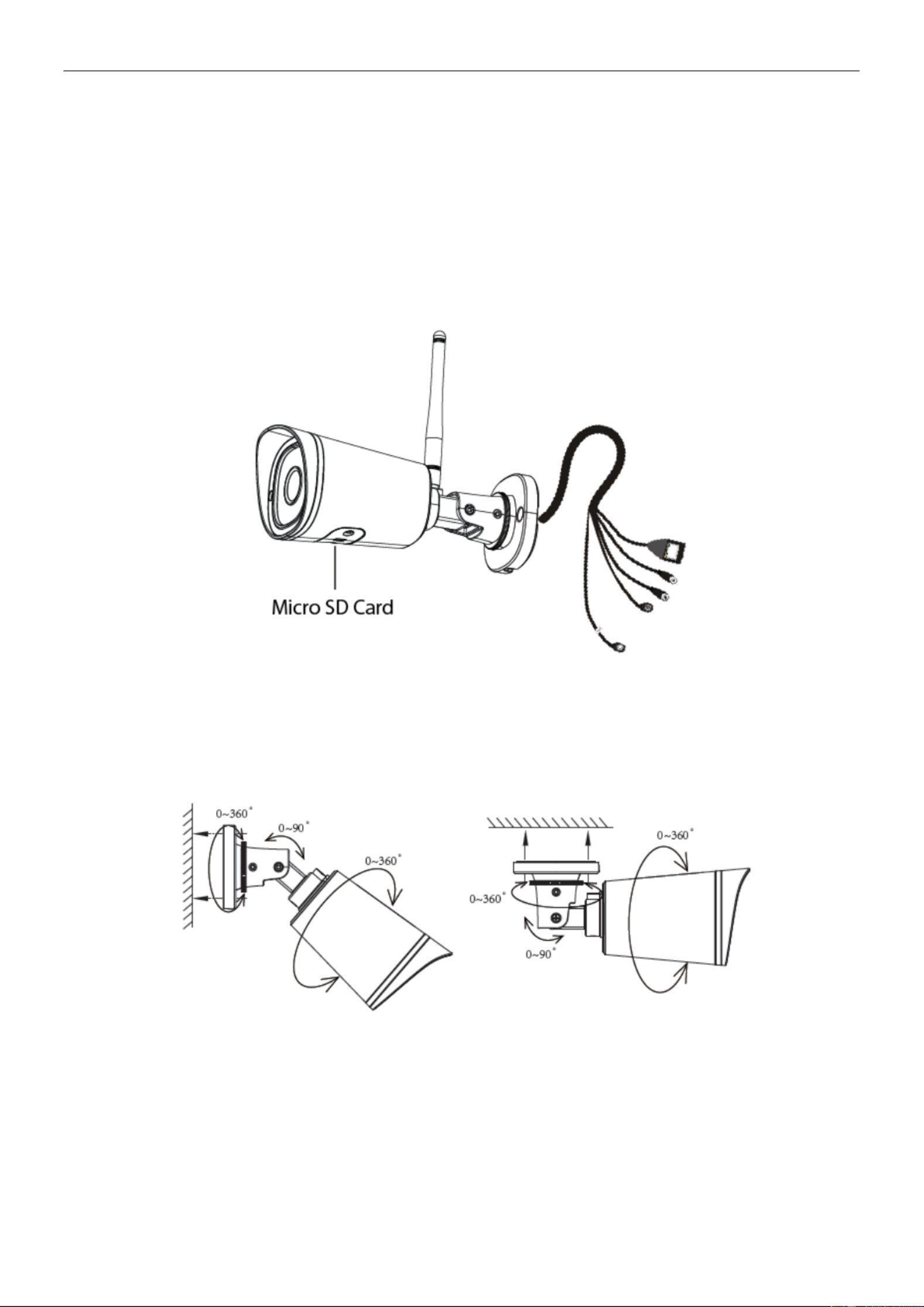
1.5 SD Card Management
The record files of the IPC can be stored in the Micro SD Card.
You need open the IP Camera, then plug the Micro SD card into Micro SD card slot inside the IP Camera.
When you plug in the Micro SD card during the camera work process, please reboot the camera again, or else
the Micro SD Card may be cannot work well.
Insert Micro SD Card in the location shown below.
1.6 Wall Installation
Fixate the camera on your preferred location and use screws to mount it. We have provided screws in the
Packaging.
NOTE: Ensure that the rain or water will not reach the connector ports at the end of the pig tail wiring. These
connectors are not weather-resistant.
The cable of an outdoor camera should, from the position where the cable is divided into several cables, be
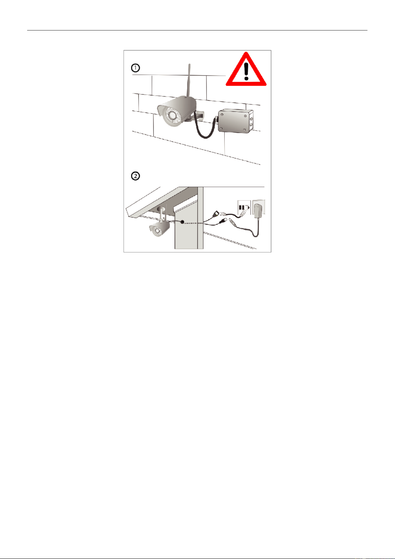
5
tted dry. Install the cable into a waterproof junction box (1) or bring the cable indoors (2).
6
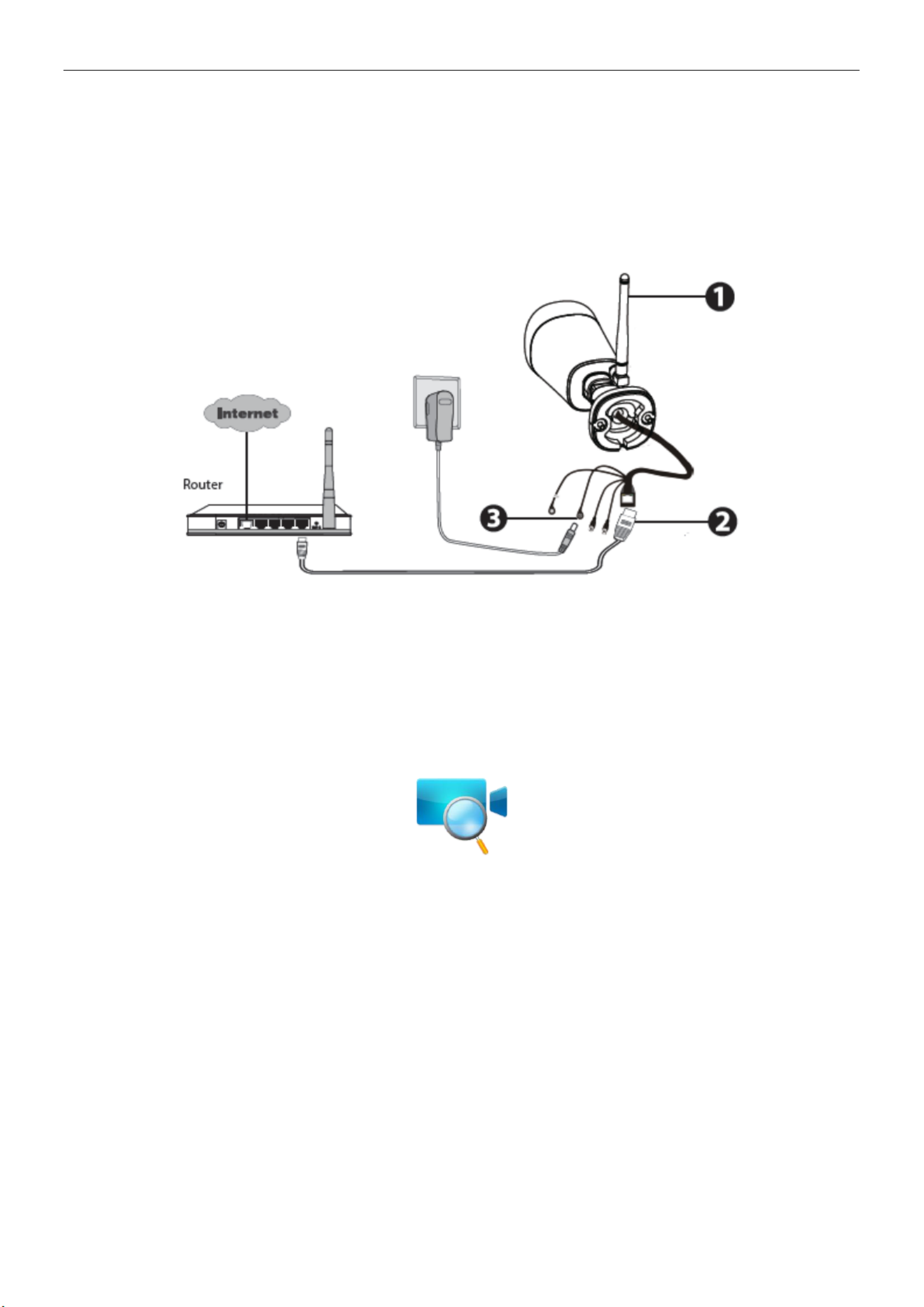
2 Access the IP Camera
2.1 Hardware Connection & Software Installation
1. Mount the antenna and make it stand vertically .
2. Connect the camera to the LAN network (Router or Switch) via network cable.
3. Connect the power adapter to the camera.
4. Download the“Equipment Search Tool” from foscam.com/tools to your computer, then access the camera directly.,
the icon shows as below:
NOTES :
If your computer (Windows OS) supports autorun function, you can nd the corresponding le in the
opened control panel.
2.2 Access the Camera In LAN
2.2.1 Wired Connection
The camera supports HTTP and HTTPS protocols, you can access the camera in two ways.
(1) Http:// LAN IP + Http Port No.
The default HTTP port NO. is 88. Double click the Search Tool icon to run, and it should nd the camera's IP
address automatically after you plug in the network cable.
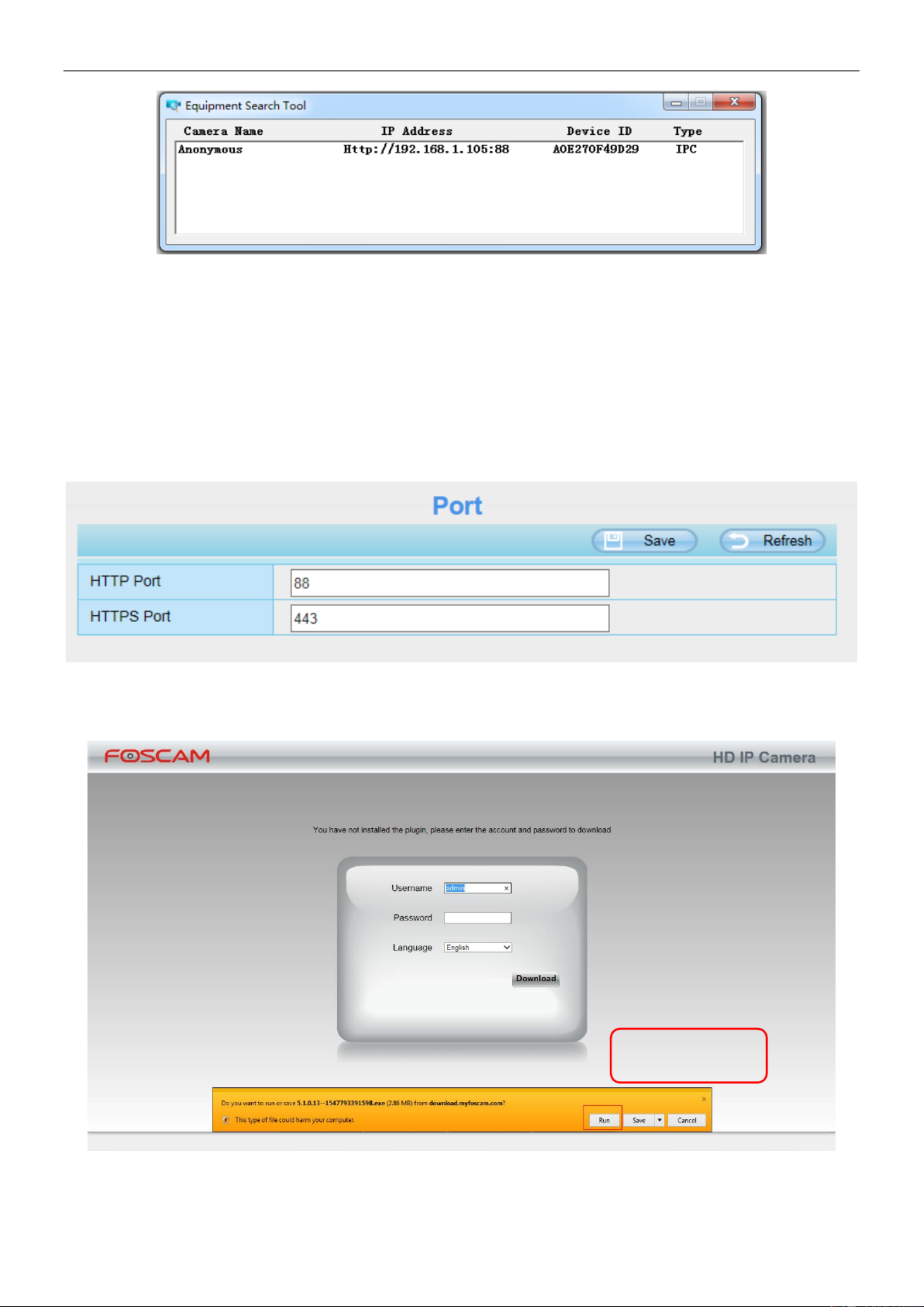
7
Double click the IP address of the camera; the camera login page should be open in your default browser.
(2) Https:// LAN IP + Https Port no.
The default HTTPS port NO. is 443. You can use the URL to access the camera: https:// LAN IP + HTTPS port
NO.
Go to Settings - Network - Port panel, you can see and change the HTTP and HTTPS port NO.
NOTE: When logging in for the rst time, you will need to download and install the add- on.
Click R un

8
2.2.2 Wireless Connection
Only some models support EZLink wireless connection , please refer to the Quick Setup Guide.
2.3 Access the Camera in WAN
2.3.1 Static IP Addresses
Users with static IP addresses after you have nished connecting the camera using the LAN IP address and
port forwarding, you can access the camera directly from Internet using the WAN IP address and port number.
How to Obtain the WAN IP address from a public website ?
To obtain your WAN IP address, enter the following URL in your browser: http://www.whatismyip.com.The
webpage at this address will show you the current WAN IP.
2.4 Using the VLC Player
This camera supports RTSP streaming, here you can view the camera using VLC player.
RTSP URL rtsp:// [user name][:password]@IP:port number/videosream
The part in the square brackets may be omitted.
user name & password :
The user name and password to access the camera. This part can be omitted.
IP: WAN or LAN IP address.
port number : If there is the RSTP port number on the Port page, you must only use RTSP port number.
otherwise, you must only use http port number.
Videostream : Here support three modes: videoMain, videoSub and audio. When the network speed is bad,
here you had better select videoSub. If you select audio, you can only hear the sound but cannot see the
video.

9
For example:
IP: 192.168.1.11
Port number: 88
User name: admin
Password: 123
Here I can enter one of the following URLs in the VLC.
1 rtsp://admin:123@192.168.1.11:88/videoMain .
2 rtsp:// @192.168.1.11:88/videoMain .
3 sp://:123@192.168.1.11:88/videoMain .rt
4 rtsp://admin@192.168.1.11:88/videoMain .
Open the VLC, and go to Media Open Network Stream option, then enter the URL into VLC.

10
Sometimes you may need to enter the user name and password again. Click OK and you can see the real-time
preview.
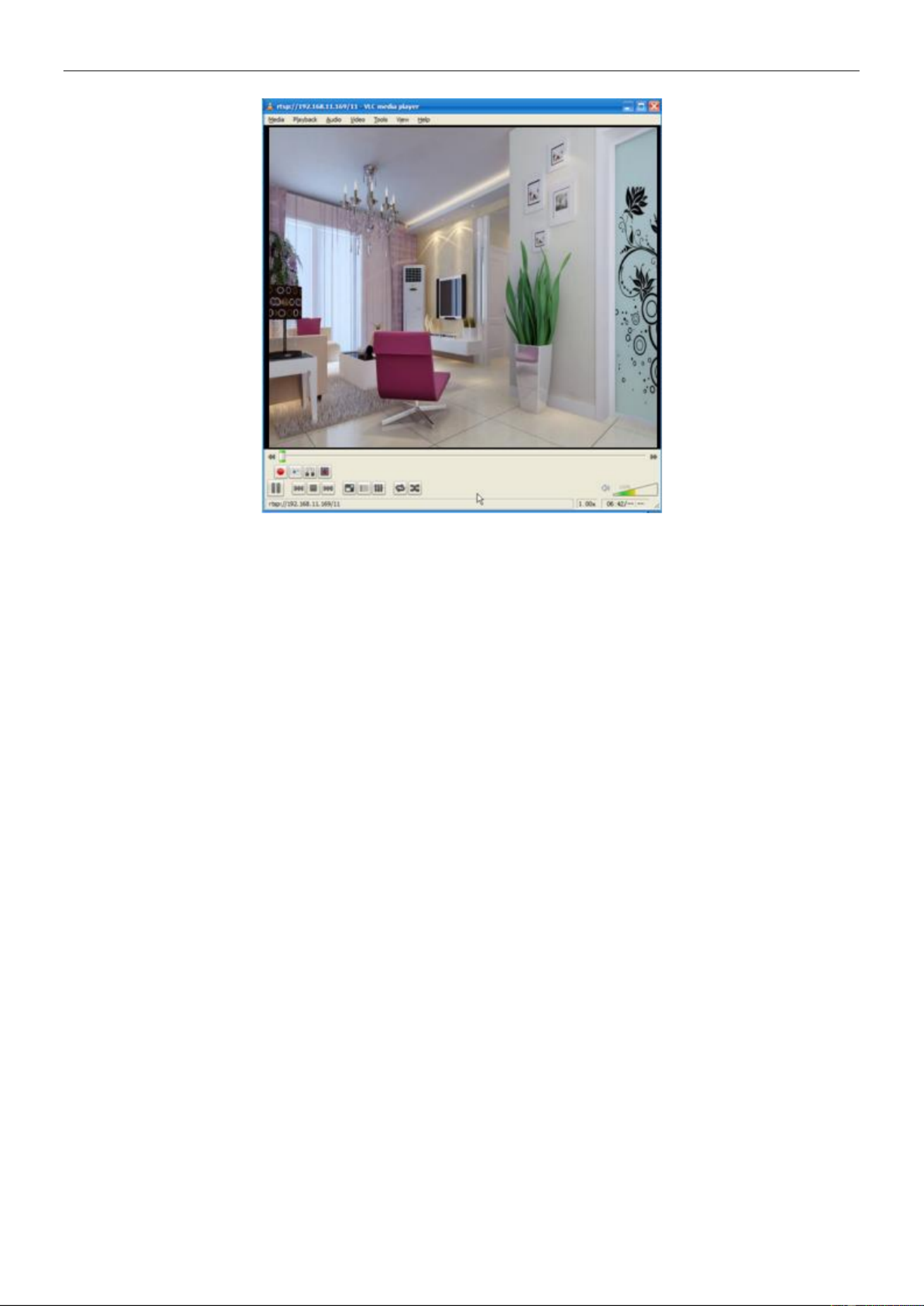
11
If you cannot play the video in the VLC player, please check the port mapping.
NOTE: If you modify the camera's username or password, you had better reboot the camera, or else the new
username and password cannot take effect when you enter the authentication in the VLC.
2.5 IP Camera Connection to the Server
Device supports ONVIF 2.2.1 protocol,You can easily access the NVR with ONVIF or server with ONVIF.

12
3 Surveillance Software GUI
Please refer to the section 2.1 if you install the camera for the rst time. You can start to learn about software
operation after finish quick installation.
3.1 Login Window
Section1 Enter the Username and password
The default administrator username is admin with no password, please change the password at first using and
prevent unauthorized users login the camera.
Section2 Stream
The camera supports two stream modes: Main stream and sub stream. If you want to access the camera form
LAN, here you can select Main stream. If you want to access the camera from Internet, here we recommend
sub stream.
NOTE: When the network bandwidth is bad you'd better select Sub Stream and the video will be more uent.
Section3 Select the language
You can select the language you need by clicking on the language dropdown list.
Section4 login the camera
Click button. Login
NOTE: When setting up your camera for the rst time, it will request that you modify the default username and /
or password if both are still set to default. Input the new username and password, click Modify to complete the
modication. You will now use the new username and password to login the camera in the future.

13
After logging in for the rst time, you will go to Setup Wizard automatically. Here you can set the basic
parameters of camera, such as camera name, camera time, wireless settings, IP conguration.
Country: Select the country.
Camera Name: You could give name for your camera.
System Time: Select the time zone you need to set the date, time,format, etc.

14
Wireless networks : Click Scan, nd the SSID of your wireless router, select and enter the password.
IP: Set IP address of the camera. You could choose to obtain an IP automatically or set the IP address
according to your needs.

15
NOTE: It needs about 1 minute to connect the camera to your router.
3.2 Surveillance Window
Section1 FOSCAM Logo / LiveVideo / Settings buttons
: FOSCAM LOGO
: Path to surveillance window. Click this button and back to the surveillance windo w
: Path to Administrator Control Panel, Click it, and it will lead to Administrator Control Panel and
1
2
3
6
4
5
7

16
do advanced settings.
Click this button to go back to the Playback panel to view the stored audio files stored in the SD Card.
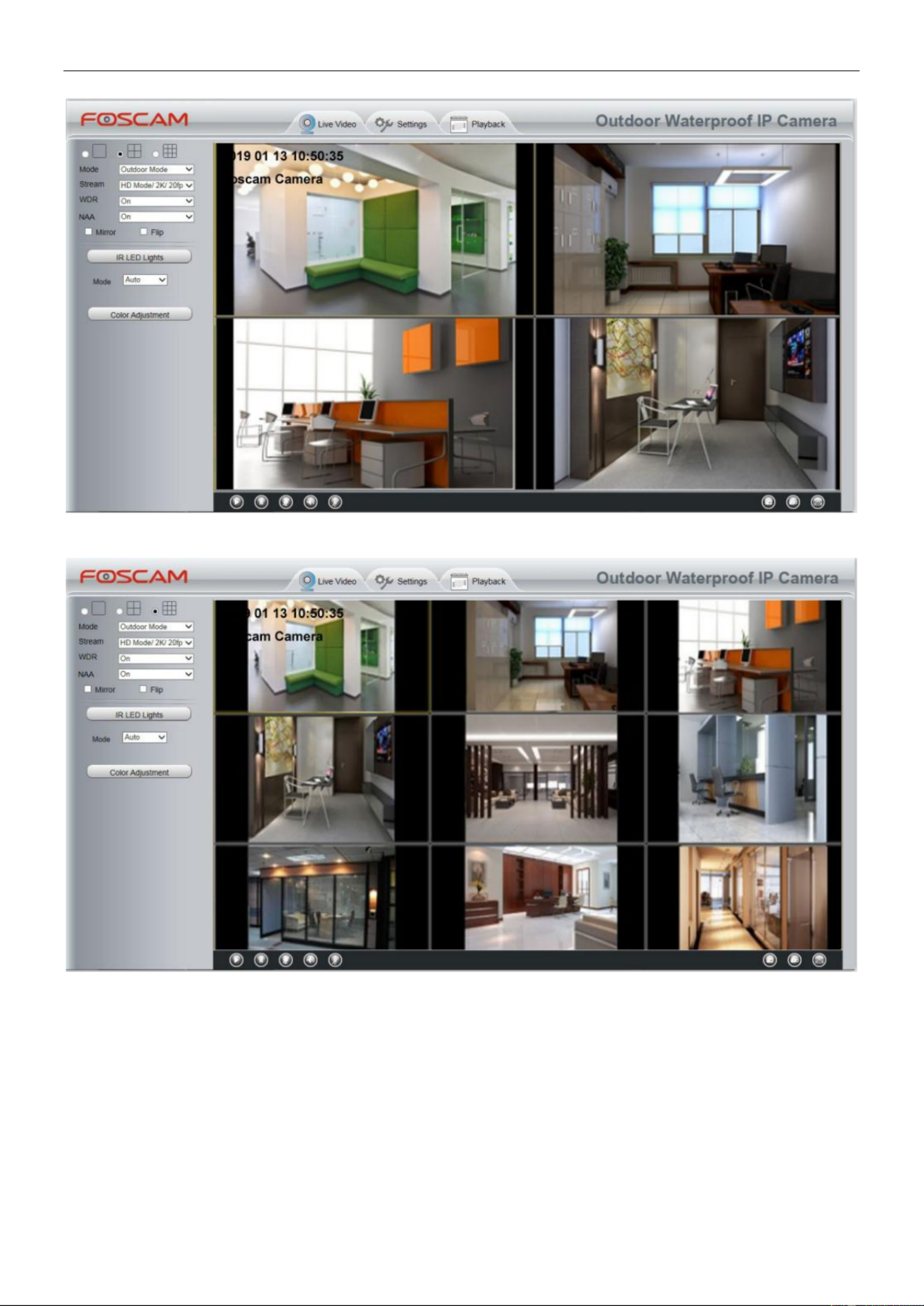
Section2 Multi-Device Window
The rmware inside the camera supports up to maximum of 9 cameras being monitoring at the same time. You
can add other cameras in multi-camera panel.
Section3 Mode/ Stream / WDR / NAA /Mirror/ Flip buttons
Mode
1) 50Hz Indoor surveillance (Region: Europe, China) ---------
2) 60Hz Indoor surveillance (Region: USA, Canada) ---------
3) Outdoor Mode Outdoor surveillance ------
Stream
The default stream supports multiple modes, For example: Equilibrium Mode / P / 1080 20fps / 1M meanings:
Stream type / Resolution / Maximum frame rate / Bit rate. (Dierent models support different specic
mode. )
1) Stream type no. Identify the stream type.
2) Resolution
The bigger the resolution, the better of the image quality is. If you are accessing the camera via internet and
want to get more uent video streaming, please select resolution VGA.
3) Maximum frame rate
The maximum frame rate is 30 fps. You should lower frame rate when the bandwidth is limited. Normally, when
the frame rate above 15, you can achieve uently video. The maximum frame rate for each model is different,
please refer to 6.3 Specication.
4) Bit Rate
Generally speaking, the larger the bit rate is, the clearer video will become. But the bit rate conguration should
combine well with the network bandwidth. When the bandwidth is very narrow, and bit rate is large, that will
lead to video cannot play well.
You can reset the stream type on Settings > Video Video Settings> panel.
17
WDR: WDR stands for High Dynamic Range. It usually refers to the method of capturing images having
"greater dynamic range between the lightest and darkest areas of an image than current standard digital
imaging methods or photographic methods". You can select from the dropdown list under sunlight or with ON
bright background.
NAA: NAA (Network Auto-Adaptability) can make IP Camera changing the real-time rate to adapt different
network conditions, which can supply better preview experience. It is OFF as default.
Section4 IR LED Lights
Click Infra led and there are three modes to adjust the infrared led: Auto, Manual and Schedule.
Auto : Select it and the camera will adjust the infra led (on or off) automatically.
Manual: Select it and turn off the infra led manually.
Schedule: Select it and the IR led light will be off at the schedule period. If you want to define or change the IR
led lights schedule time, please go to Settings > Video > IR LED Schedule page.
Section5 Color Adjustment
In this page, you can tune Hue, Brightness, Contrast, Saturation, and Sharpness to get higher quality.

18
Section6 OSD
If you have added time and camera name in the video, you can see it in the live window.
Go to Settings > Basic settings > Camera name panel, and you can change another device name. The
default device name is anonymous.
Go to Settings > Basic settings > Camera time panel and adjust the device time.
Go to Settings > Video > On Screen Display panel, you can add or no add OSD.
Section7 Play / Stop / Talk / Audio / Snap / Record / Full screen button
1 Play ------ Click it to play the video of the camera
2 Stop ------ Click it to stop the video of the camera
3 Talk------ Click the button and the icon will become to , then talk to the microphone that connected with
PC, people around the camera can hear your voice if the camera has connected with audio output device.
Click the icon again and stop talking.
4 Audio------ Click the button and the icon will become to , you can hear the sound around the camera if
the camera has connected with other audio input device through the Audio Input port of the camera, Click the
icon again and stop audio.
5 Volume ----- Click the button and the icon will become to , you can set the volume.
6 Snap----- Click it to make snapshot and it pop up a window which picture you snapshot, right click in the
window and save the picture to anywhere you want.
7 Record ----- Click the icon and the camera start recording, you can see a green dot in the live window.
Click again and stop recording. The default storage path is C:\IPCamRecord. You can change the storage path:
Go to Settings > Record > Storage Location panel.
8 Full Screen ------ Click it to make full-screen, or you can double click the surveillance screen to make
full-screen. Double click again and exit full-screen.
1
2
3
6
7
8
4
5

19
Onscreen Mouse Control
Right click the mouse and you can adjust the screen ration, full screen and Zoom up.
Keep Ration: Select it and the camera will adjust the size of live window based on the computer monitor
automatically.
Sometimes there is a black border around the video, please select Keep ration to get a better visual quality.

20
Full Screen : Select it and Click it to make full-screen, press ESC and exit full-screen.
Zoom Up / Down: Click it and the live view will be digital zoomed up, then click Zoom Down and the live view
back to original size.
NOTES:
1. This camera don't support Pan / Tilt function, so here can not allow to use Screen PTZ.
2. For Mac OS, the plugin cannot support Onscreen Mouse function, so you cannot allow to use it.

21
4 Advanced Camera Settings
Click the button Settings, goes to Administrator Control Panel to make advanced camera settings.
4.1 Setup Wizard
The way to set it, you could refer to section 3.1.
4.2 Device Status
Device Status contains four columns: Device Information, Device Status, Session Status and Log, it will show
you various information about your camera.
4.2.1 Device Information
Camera Name: The Device Name is a unique name that you can give to your device to help you identify it.
Click Basic Settings and go to Device Name panel where you can change your camera name. The default
device name is anonymous.
Camera ID: Display the MAC address of your camera. For example Device ID is 008414350787, the same
MAC ID sticker is found at the bottom of the camera.

22
Camera Time: The system time of the device. Click Basic Settings and go to Camera Time panel and adjust
the time.
System Firmware Version : Display the System Firmware version of your camera.
Application Firmware Version: Display the application firmware version of your camera.
Plug-In Version: Display the plug-in version of your camera
4.2.2 Device Status
On this page you can see device status such as Alarm status, NTP status, WIFI status and so on.
4.2.3 Session Status
Session status will display who and which IP is visiting the camera now.

23
4.2.4 Log
The log record shows who and which IP address accessed or logout the camera and when.
Reboot the camera and clear the log records.
4.3 Basic Settings
This section allows you to configure your Camera Name, Camera Time, Mail, User Accounts and Multi-Device.
4.3.1 Camera Name
Default alias is anonymous. You can define a name for your camera here such as apple. Click save Save to
your changes. The alias name cannot contain special characters.
4.3.2 Camera Time
This section allows you to configure the settings of the internal system clocks for your camera.
Click Setting > Basic Setting > Camera Time to enter the Camera Time setting page.
Click the page number and go to the
corresponding page to see more logs .
Fill in one page number, click Go button
and go to the corresponding page .

24
Time Zo ne: Select the time zone for your region from the drop-down menu.
Sync with NTP server: Network Time Protocol will synchronize your camera with an Internet time server.
Choose the one that is closest to your camera.
Sync with PC / Terminal: Select this option to synchronize the date and time of the Network Camera with your
computer.
Manually: The administrator can enter the date and time manually. Please select the date and time format.
use DST: Select the use DST (Daylight Saving Time, to set the clock ahead of the real-time), then set the start
time and end time of the DST, select the daylight saving time from the drop-down menu at last.
Click Save button to submit your settings.
NOTE: If the power supply of camera is disconnect, you need set the camera's time again.
4.3.3 User Accounts
Here you can create users and set privilege, visitor, operator or administrator. The default administrator
user accounts are admin with a blank password.
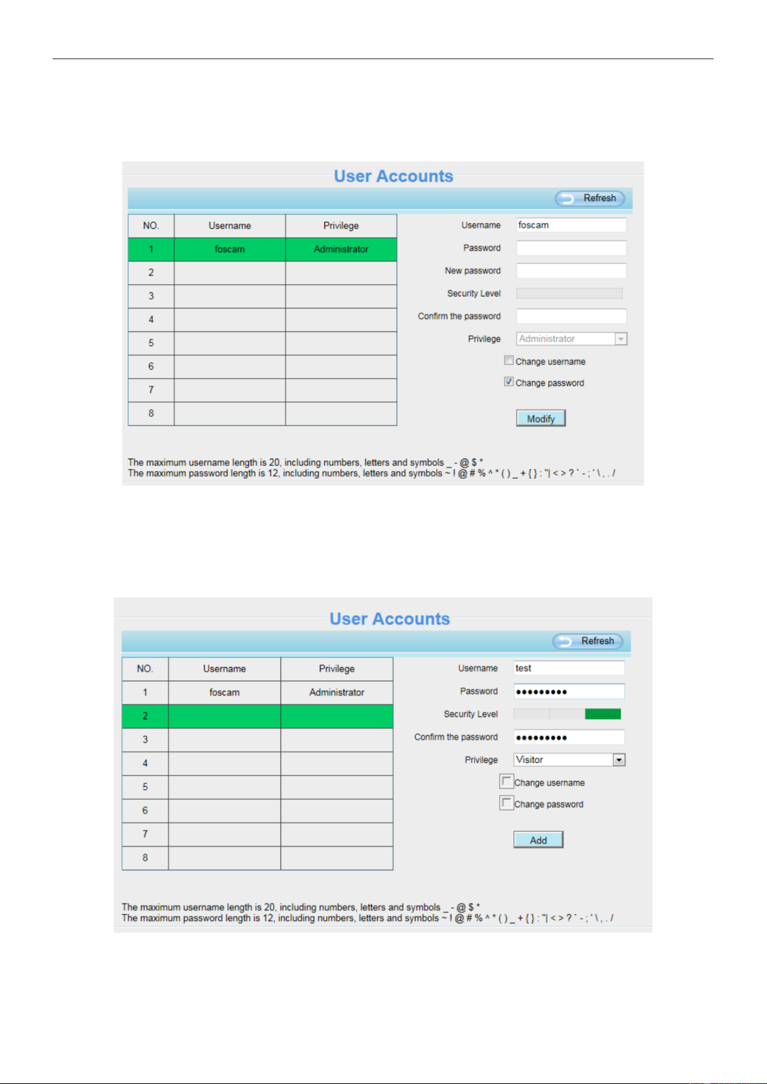
25
How to change the password?
Firstly, select the account which you want to change the password, then select Change Password, enter the
old password and the new password, lastly click modify to take effect.
How to add account ?
Select one blank column, then enter the new user name, password and privilege, last click Add to take effect.
You can see the new added account on the Account list.

26
Delete: Select the account which you want to delete, then click Delete button to take eect.
NOTE: The default administrator account cannot be deleted, but you can add other administrator users.
4.3.4 Multi-Camera
If you want to view multi-surveillance screens on one window, you need to login one camera, and set it as the
main device, and do Multi-Device Settings, add other cameras to the first one camera. Before you do
multi-cams settings, you need to assign different port such as 81, 82, 83, 84, 85, 86, 87, 88 to the cameras if
there is 8 cams installed.
The rmware within the camera can support a maximum of 9 devices monitoring all at the same time. This
page you can both add FOSCAM MJPEG and H.264 series cameras to the first camera and view
multi-surveillance screen on one window.
Add cameras in LAN
In Multi-Device Settings page, you can see all devices searched in LAN. The 1st Device is the default one. You
can add more cameras in the list in LAN for monitoring. The camera's software supports up to 9 IP Cameras
online simultaneously. Click The 2nd Device and click the item in the Device List in LAN, the Alias, Host and
Http Port will be lled in the boxes below automatically. Enter the correct username and password then click
Add. Add more cameras in the same way.

27
Camera Model: Our Company produces two series cameras: MJPEG and H.264. Here will show you which
series the camera belongs to.
Back to Surveillance Windows, and click Four Windows option, you will see four cameras you added.
2 Enter the User name and
password of the 2nd camera .
1 Click it, camera model, alias,
host and HTTP Port will be
lled in the following boxes
automatically .
3 Click Add to take eect .
28
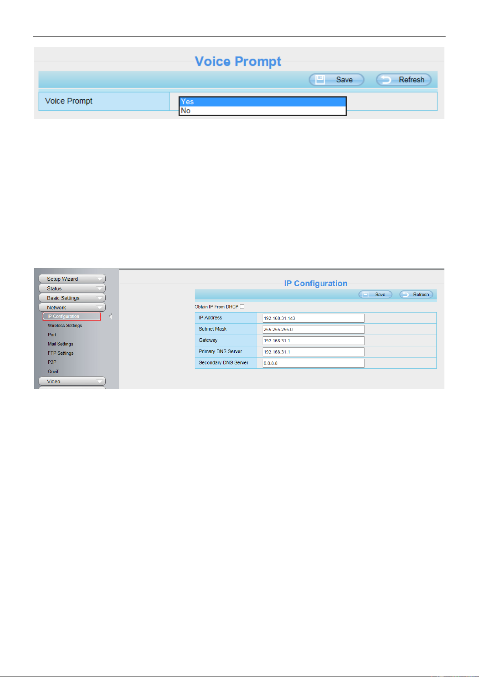
4.3.5 Voice Prompt
On this page, you can enable or disable voice prompt. Select “Yes” to enable or select “No” to disable.
If select Yes , you can hear the voice prompt after connect the audio output device. ” ”
29
4.4 Network
This section will allow you to congure your camera's IP, Wireless Settings, Port, Mail Settings and FTP
Settings.
4.4.1 IP Conguration
If you want to set a static IP for the camera, please go to IP Conguration page. Keep the camera in the same
subnet of your router or computer.
Changing settings here is the same as using the Equipment Search Tool.
It is recommended that you use the subnet mask, gateway and DNS server from your locally attached PC. If
you don't know the subnet mask, gateway and DNS server, you can check your computer's local area
connection as follows:
Control Panel > Network Connections > Local Area Connections > Choose Support > Details.

30
If you don't know the DNS server, you can use the same settings as the Default Gateway.
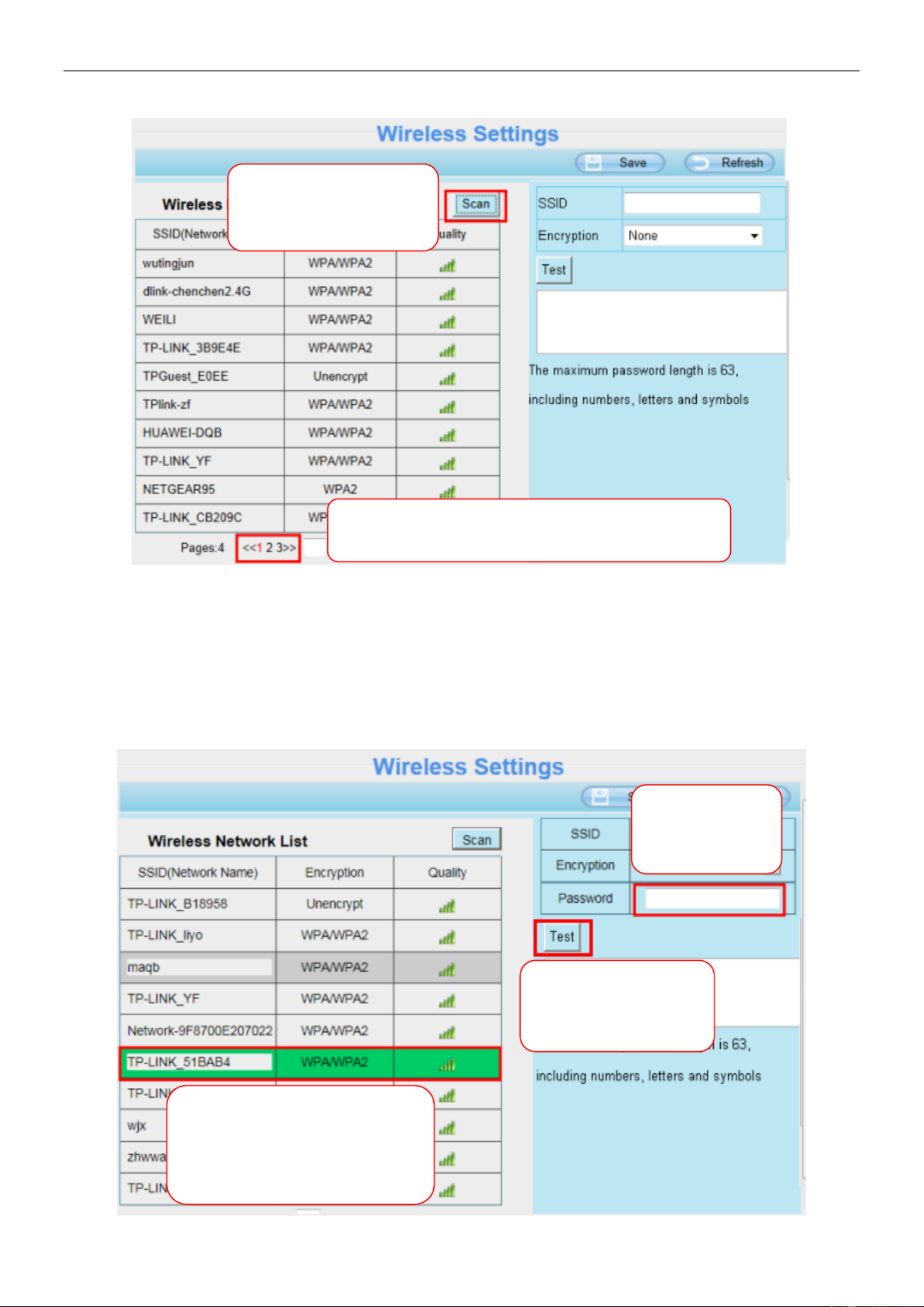
4.4.2 Wireless Settings
Step 1: SettingsChoose on the top of the camera interface, and go to the "Network" panel on the left side of
the screen, then click Wireless Settings.
Click the Scan button and the camera will detect all wireless networks around the area. It should also display
Set the same Subnet Mask and
gateway of the camera with your
PC.
There are two DNS servers. You
can set any of them. Same with
gateway is also OK.
31
your router in the list.
Step 2: Click the SSID (name of your router) in the list, the corresponding information related to your network,
such as the name and the encryption, will be lled into the relevant elds automatically.
You will only need to ll in the password of your network. Make sure that the SSID, Encryption and the
password you lled in are exactly the same for your router.
Click the Page number to see other wireless
networks devices if there are more than 10.
Click the Scan button
to search for wireless
networks.
1 Click the SSID of your router
and the relevant information
will be lled in the elds
automatically.
2 Enter the
password of
your router .
3 Click Test to check
if the password is
correct or not.

32
Step 3: Please click on the Save button after all settings have been entered and disconnect the network cable.
Never shut down the power of the camera until the IP camera is able to connect to the wireless network.
The LAN IP address will disappear on the window of Equipment Search Tool when the camera is configuring a
wireless connection. Wait about 1 minute, the camera should obtain a wireless connection, and the LAN IP of
the camera will show again on the window of the Equipment Search Tool The IP address may have changed
after the camera receives a wireless connection; we recommend setting a static local IP address if this IP
address changes by right clicking the camera in Equipment Search Tool, setting a static IP, and pushing OK .
Congratulations! You have set up the wireless connection of the camera successfully.
NOTE: If you fail to make a wireless connection, please refer to your seller or contact us directly for
assistance.
4.4.3 Port
This camera supports HTTP Port / HTTPS Port / ONVIF Port. HTTP Port is used to access the camera
remotely.
HTTP port: By default, the HTTP is set to 88. Also, they can be assigned with another port number between 1
and 65535. But make sure they can not be conict with other existing ports like 25, 21.
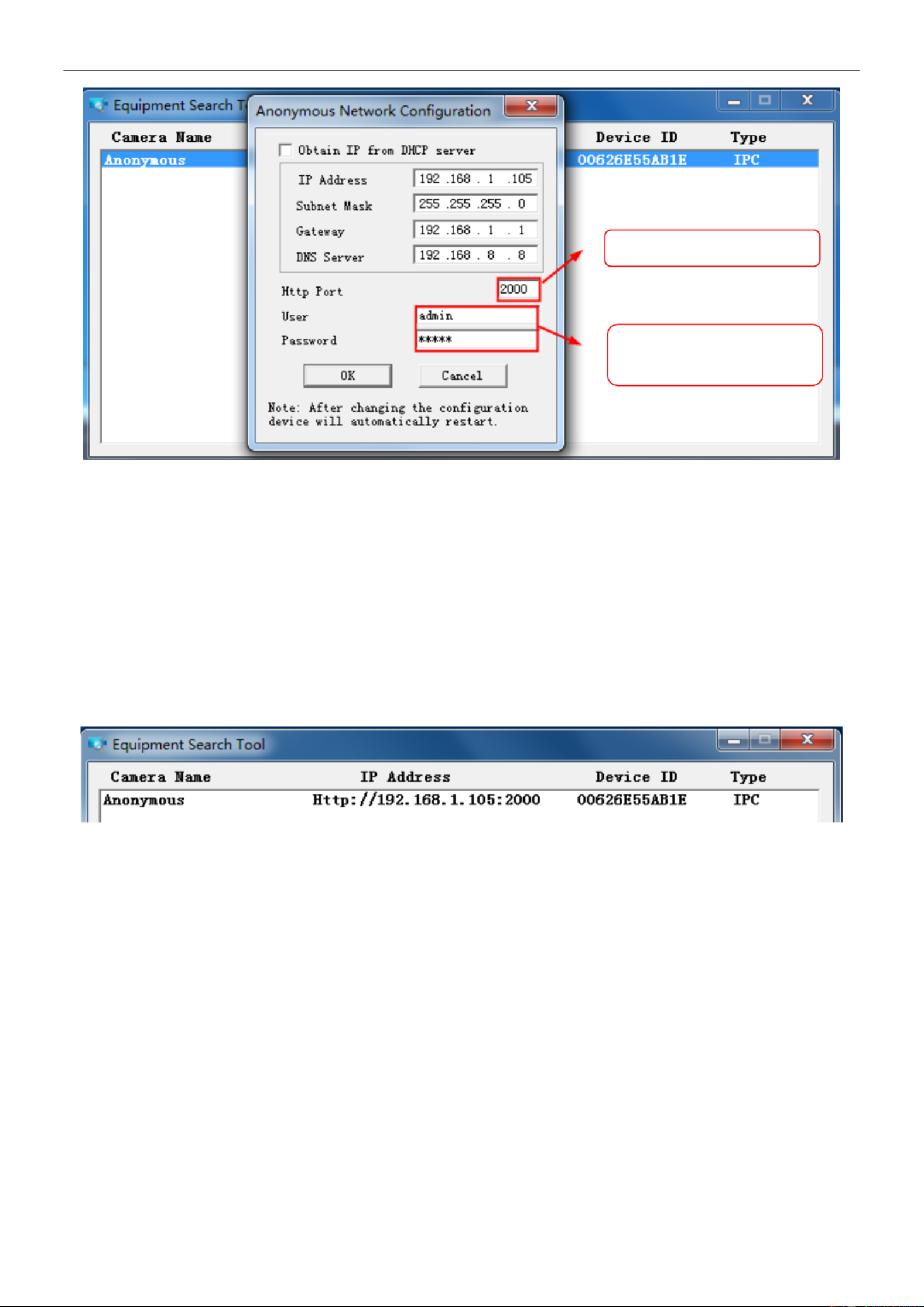
Another way to change the HTTP port no.
Step 1: Open the Equipment Search Tool, select the camera you would like to change the port of, right click on
the IP address, and click on "Network Conguration", this brings up the network conguration box .
Select which camera
you’d like to change the
port for, and right click .
33
Step 2: Enter the username and password of the Administrator (default username is admin with a blank
password), and click to apply changes. OK
Step 3: Wait around 10 seconds, you'll see that the camera's LAN IP address has changed. In our example it
was changed to 2000, so we see http://192.168.1.105:2000 in Equipment Search Tool. Also, the LAN IP
address is now fixed at a static IP address of http://192.168.1.105:2000. This IP address will not change even if
the camera is powered off and back on, the camera will remain on this LAN IP address. This is very important
that a static LAN IP address is set, or you may have problems later with remote access and seeing the camera
remotely if the camera loses power and reconnects on a different LAN IP address. Make sure you set a static
LAN IP address!
Figure 4.1
NOTE: If the camera cannot be accessed, please make sure the port forwarding is succeed.
HTTPS Port: The default port is 443. You can use the url to access the camera: https:// IP + HTTPS port.
ONVIF Port: By default, the ONVIF port is set to 888. Also, they can be assigned with another port number
between 1 and 65535 (except 0 and 65534). But make sure they can not be conflict with other existing ports.
RTSP Port : The default port is 554,only some IP Cameras have RTSP port.
4.4.4 Mail Settings
If you want the camera to send emails when motion has been detected, here Mail will need to be configured.
Modify the Http Port .
Enter the Username and
password, click OK.

34
1 SMTP Server / Port / Transport Layer Security ----- Enter SMTP server for sender. SMTP port is usually
set as 25. Some SMTP servers have their own port, such as 587 or 465, and Transport Layer Security usually
is None. If you use Gmail, Transport Layer Security must be set to TLS or STARTTLS and SMTP Port must be
set to 465 or 25 or 587, which port you choose should be decided by which Transport Layer Security you
select.
2 SMTP Username / password ----- ID account and password of the sender email address
3 Sender E-mail----- Mailbox for sender must support SMTP
4 Receiver----- Mailbox for receiver need not support SMTP, you can set 4 receivers
5 Save----- Click Save to take effect
6 Test ----- Click Test to see if Mail has been successfully configured.
Click Test to see if Mail has been successfully congured.
1
2
3
4
5
6

35
If the test success, you can see the Success behind the Test, at the same time the receivers will receive a test
mail.
If the test fails with one of the following errors after clicking Test, verify that the information you entered is
correct and again select Test .
1) Cannot connect to the server.
2) Network Error. Please try later.
3) Server Error.
4) Incorrect user or password.
5) The sender is denied by the server. Maybe the server need to authenticate the user, please check it and try
again.
6) The receiver is denied by the server. Maybe because of the anti-spam privacy of the server.
7) The message is denied by the server. Maybe because of the anti-spam privacy of the server.
8) The server does not support the authentication mode used by the device.
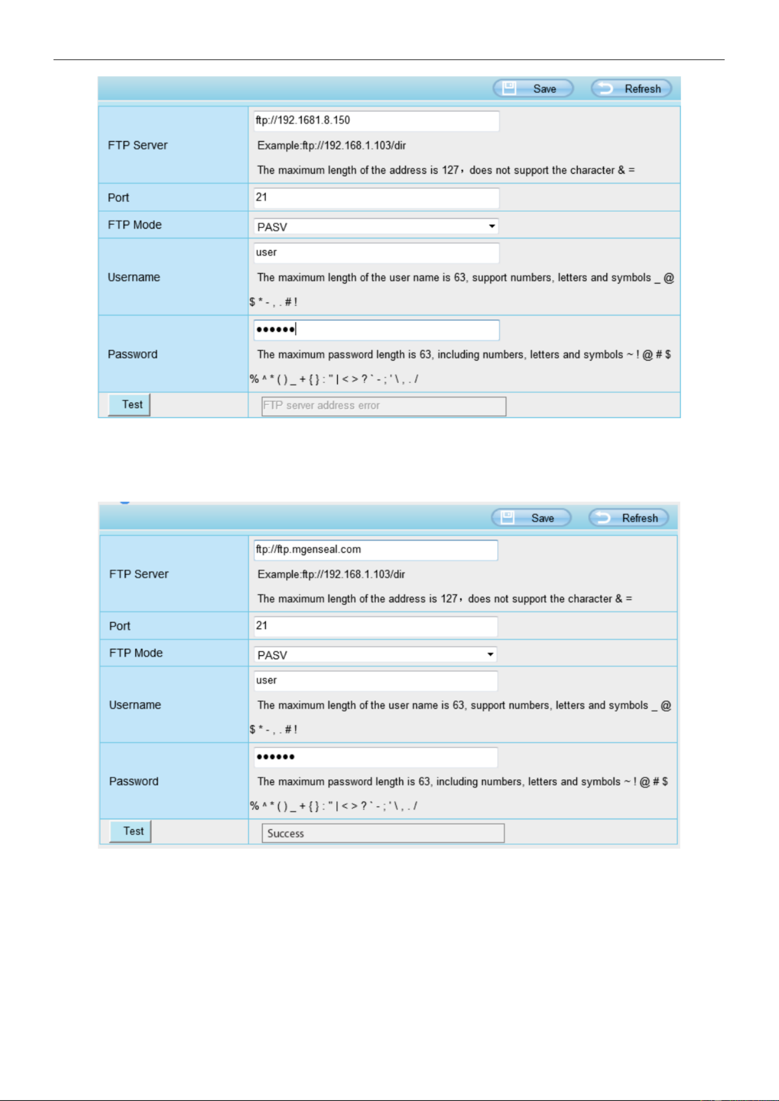
4.4.5 FTP Settings
If you want to upload record images to your FTP server, you can set FTP Settings.
Test result .
36
FTP server: If your FTP server is located on the LAN, you can set as Figure as above.
If you have an FTP server which you can access on the internet, you can set as below.
Port : Default is port 21. If changed, external FTP client program must change the server connection port
accordingly.
FTP Mode : Here supports two modes: PORT and PASV.
Username / password: The FTP account and password.
Click Save to take effect.
Click Test to see if FTP has been successfully congured.

37
4.4.6 P2P
Access the camera by smart phone (Android or iOS operating system),please refer to the Quick Setup Guide.
First of all, you need to open the P2P function of the camera at Settings > Network > P2P.
4.5 Video
This section allows you to congure Video stream settings, On screen display and Snapshot settings.
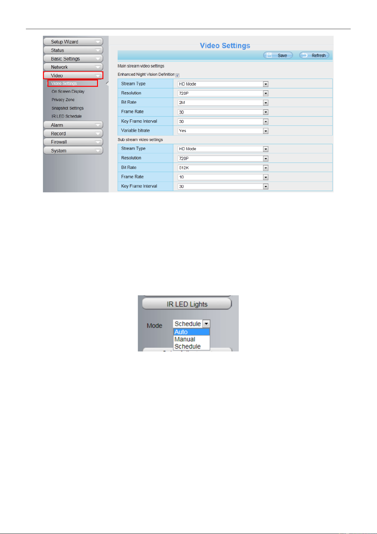
4.5.1 Video Settings
There are two ways to set the stream video settings. They are main stream video settings and sub stream
video settings.

38
Enhanced Night video Denition: The camera will automatically drop the frame to extend the recording time
in the night.
Stream Type: There are four types to identify different streams you have set. If select the HD Mode, the
clearer video will become, and it will take up more bandwidth; If select the Smooth Mode, the bandwidth is very
narrow, and bit rate is large, that will lead to video can not play well. The Equilibrium Model is a value between
HD Mode and Smooth Mode.
Resolution: The camera supports multiple types, For example: 1080P, 960P, 720P, VGA. The higher the
resolution is, the clearer video will become. But the code ux will become larger too, and it will take up more
bandwidth. (Dierent models support dierent specific types. )
Bit Rate: Generally speaking, the larger the bit rate is, the clearer video will become. But the bit rate
conguration should combine well with the network bandwidth. When the bandwidth is very narrow, and bit
rate is large, that will lead to video can not play well.
Frame Rate: Note that a larger frame size takes up more bandwidth. You should lower frame rate when the
bandwidth is limited. Normally, when the frame rate above 15, you can achieve uently video.The maximum
frame rate for each model is dierent, please see the 6.3 Specication.
Key Frame Interval: The time between last key frame and next key frame. The shorter the duration, the more
likely you will get a better video quality, but at the cost of higher network bandwidth consumption.
Rate Control Mode: There are three rate control modes.
CBR: Constant Bit Rate, it means that the Bit Rate is constant.
VBR: Variable Bit Rate, the camera will change the video bit rate according to the situation, but will not more
than the maximum parameter "Bit Rate".
LBR: Low Bit Rate. If you can select the LBR, then you can slide the scroll bar to choose percentage of the bit
rate. By reducing the bit rate, so that the camera can obtain a better image at low bandwidth.
4.5.2 On Screen Display
This page is used to add timestamp and device name on the video.
Display Timestamp: There are two options: Yes or NO. Select Yes and you can see the system date on the
video.
Display Camera Name: There are two options: Yes or NO. Select Yes and you can see the device name on
the video.

39
4.5.3 Snapshot Settings
In this page you can set the snapshot pictures' image quality and the storage path.
Manual snap Quality: Low, Middle and High. The higher the quality, the picture will be clearer.
Pictures Save To: FTP or SD card. If you have done FTP and Alarm settings, when alarming, the camera will
snap pictures to the FTP or SD card automatically.
If you select the FTP, you can set the le name which the picture save to. For example: le name is "NAME",
the snapshot picture is "NAME_20150605-180000.jpg".
Enable timing to capture
To enable capture interval, follow the steps below:
1 Select Enable timing to capture
2 Capture interval: The interval time between two captures.
3 Select the capture time
Capture anytime
Click the black button up the MON, you will see all time range turn red. When something moving in the
detection area at anytime, the camera will capture.
Specify an capture schedule
Click the week day words, the corresponding column will be selected. For example, click TUE, the all
column of TUE turns to red, that means during Tuesday whole day, the camera will capture.
Press the left mouse and drag it on the time boxes, you can select the serial area,
4 Click Save button to take effect.

40
4.5. IR LED Schedule 4
On this page you can set the schedule time for switching IR LED lights. When parameter Mode is set to the
Schedule on the Live Video window, At these schedule time, the IR LED lights will be turned off.
4.6 Detector
4.6.1 Motion Detection
IP Camera supports Motion Detection Alarm, when the motion has been detected, it will send emails or
upload images to FTP.
To enable motion detection, follow the steps below:
1 Enable Motion detection
2 Sensitivity---- It supports three modes: Low, Middle and High. The higher the sensitivity, the camera will be
more easily alarmed. Select one motion sensitivity.
3 Trigger interval--- The interval time between two motion detections. Here supports 5s / 6s / 7s / 8s / 9s / 10s
/ 11s / 12s / 13s / 14s / 15s. Select one interval time.
4 There are some alarm indicators :
A Camera Sound PC Sound and

41
If the camera has connected with a speaker or other audio output device, if you select Camera Sound or PC
Sound, when the motion has been detected, the people around the camera will hear beep alarm sound.
B Send E-mail
If you want to receive alarm emails when motion is detected, you must select Send E-mail and set Mail
Settings rst.
C Take Snapshot
If you select this checkbox, when the motion has been detected, the camera will snap the live view window as
a still picture and load it to the FTP. Make sure you have set FTP and set FTP as the storage path in Video >
Snapshot settings panel.
Time interval : The interval time between two pictures.
D Recording
If you select this checkbox, when the motion has been detected, the camera will recording and load it to the
FTP server. Make sure you have set FTP and set FTP as the storage path in Video->Snapshot settings panel.
E Push message to the phone
If you select this checkbox, when the motion has been detected, the camera will push the message to the
phone which has been connected the camera.
5 Set detect area
Click set detect area and it pop up a window, then you can draw the detection area. Click Back button after
settings. When something moving in the detection area, the camera will alarm.
6 Alarm Schedule
A Alarm anytime when motion is detected
Click the black button up the MON, you will see all time range turn red. When something moving in the
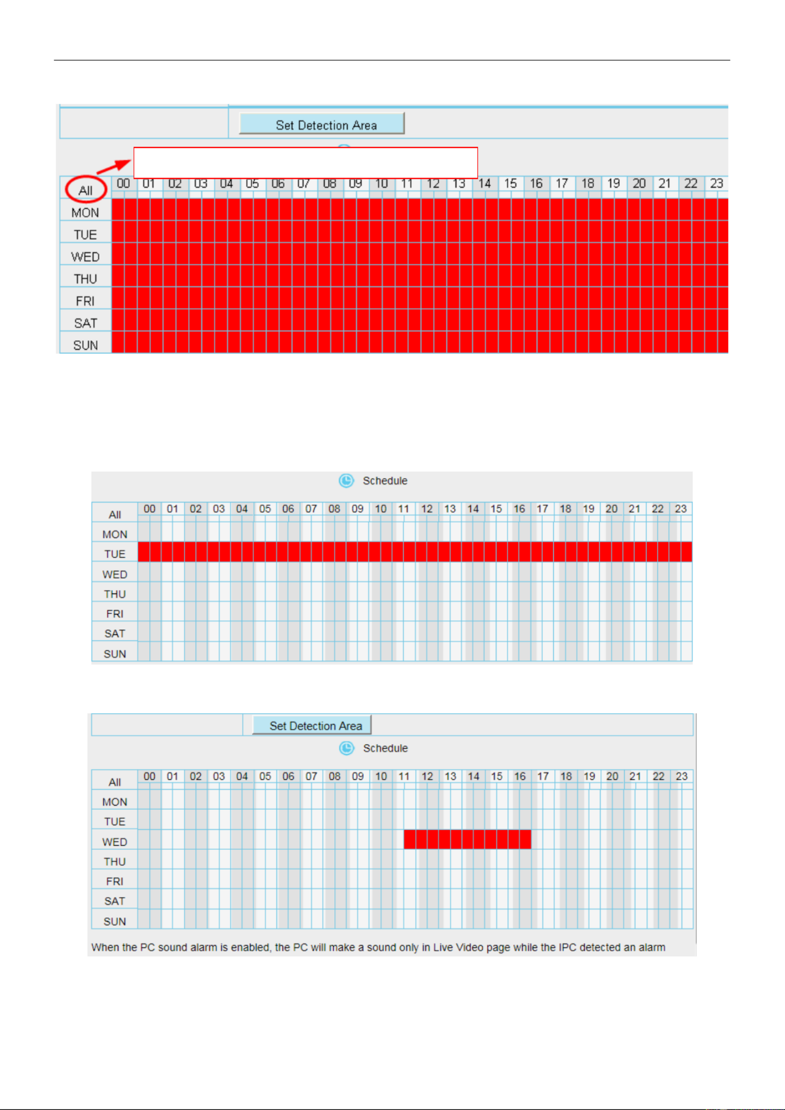
42
detection area at anytime, the camera will alarm.
B Specify an alarm schedule
Click the week day words, the corresponding column will be selected. For example, click TUE, the all column
of TUE turns to red, that means during Tuesday whole day, when something moving in the detection area, the
camera will alarm.
C Press the left mouse and drag it on the time boxes, you can select the serial area,
7 Click Save button to take effect. When the motion is detected during the detection time in the detection area,
the camera will alarm and adopt the corresponding alarm indicators.
Click this button and select all time range.
43
NOTE: You must set the detection area and detection schedule, or else there is no alarm anywhere and
anytime.
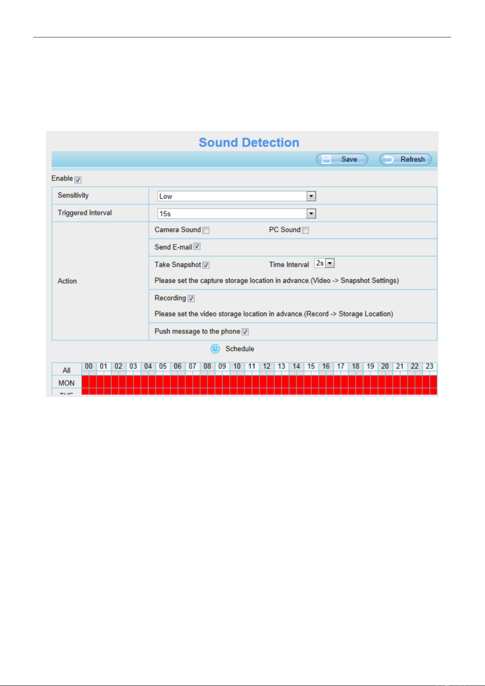
4.6.2 Sound Detection
When the ambient sound over a certain decibel ,the sound alarm will be triggered.
If the Sensitivity is set to , the camera will detect the sound whose more than 55db. High
If the Sensitivity is set to , the camera will detect the sound whose more than 65db. Medium
If the Sensitivity is set to , the camera will detect the sound whose more than 75db. Low
If the Sensitivity is set to , the camera will detect the sound whose more than 85db. Lower
If the Sensitivity is set to , the camera will detect the sound whose more than 95db. Lowest

46
Record frame: There are six frame selections, such as 1 / 30, 4 / 30, 8 / 30, 15 / 30, 24 / 30, 30 / 30.
Recommended default is 4 / 30. The greater the Frame rate is, the sharper picture quality is, and the greater of
storage space is, the shorter the storage time is.
Record full strategy: When the SD card is full, you can choose to cover the previous recording, or stop
recording.
Audio Record : You can choose Yes or No.
NOTES:
Scheduled recording only supports video saved to the SD card or FTP server.
The schedule recording will stop while alarm recording is beginning, and it will continue automatically after
alarm recording end.
4.7.5 SD Card Management
The SD card Slot inside the camera, if you want to install or remove the SD card, you need to open the
camera.
When you plug in the SD card during the camera work process, please reboot the camera again, or else the
SD Card may be cannot work well.
Go to the Settings Status Device Status > > page, you can see the SD card status.
The default storage path of alarm record les is SD card, when the available size of SD card is less than 256M,
the old record les will be deleted automatically.
47
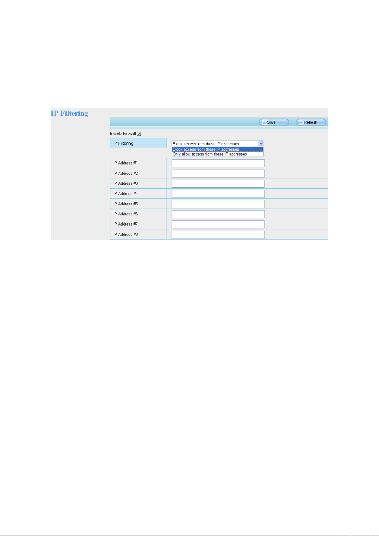
4.8 Firewall
This section explains how to control the access permission by checking the client PC's IP addresses. It is
composed of the following columns: Block access from these IP addresses Only allow access from and
these IP addresses.
Enable rewall, If you select Only allow access from these IP addresses and ll in 8 IP addresses at most, only
those clients whose IP addresses listed in the Only allow access from these IP addresses can access the
Network Camera. If you select Block access from these IP addresses, only those clients whose IP addresses
are in the IP list cannot access the Network Camera.
Click to take eect.Save
4.9 System
In this panel, you can back up / restore your camera settings, upgrade the rmware to the latest version,
restore the camera to default settings and reboot the device.
4.9 Back-up & Restore .1
Click Backup to save all the parameters you have set. These parameters will be stored in a bin le for future
use.
Click Browse and select the parameters le you have stored, then click Submit to restore the restore the
parameters.

48
4.9.2 System Upgrade
Click Download the Latest Firmware, you will see the following screen. And click to save the rmware Save
on your computer locally.
Your current rmware version will be displayed on your screen. You may go to the Status Device >
Information page to check for the latest rmware versions available.
Click , choose the correct bin le and then click Browse System upgrade.
Don't shut down the power during upgrading. After upgrading, you can see the upgrade result.
Upgrade Firmware by Equipment Search Tool
Double click the Equipment Search Tool shot icon , select the Camera IP that you want to upgrade the
rmware. Then select Upgrade Firmware and enter the username and password, choose the rmware le, and
upgrade.

49
CAUTION :
We recommend that you regularly update your camera to the latest available software and rmware versions
to help ensure the best experience for your camera.
NOTE:
1) Please ensure you have download the correct rmware package for your camera before upgrading. Read
the upgrade documentation (readme.txt le) in the upgrade package before you upgrade.
2) Upon downloading the rmware check the sizes of the .bin les. They must match the size in the
readme.txt file. If not, please download the rmware again until the sizes are the same. Your camera will
not function correctly if a corrupt .bin file is used.
3) Never shut down the power of the camera during upgrade until the IP camera restart and get connected.
4) After upgrade successfully, please clear the cache of browser, uninstall the old plugin and re-install it, then
reset the camera to the default factory settings before using the camera.
4.9.3 Patch Installation
Click Browse to select the correct patch le, and then click Install Patch to install the patch. Do not turn off the

50
power during it installing. After installing is complete, you will receive a system prompt.
4.9 Factory Reset .4
Click Factory Reset button and all parameters will return to factory settings if selected.
The default administrator username is admin with a blank password.
4.9 Reboot .5
Click Reboot to reboot the camera. This is similar to unplugging the power to the camera.

51
5 Playback
On this page you can view the record les stored in the SD card.
Section 1 Dene the Record les time and Type
: The storage path of record les
: Here supports three types: current day, current month and All records. Another way,
select the time on the time&date manually.
: The type of records les, Here supports two typs: Normal record, Alarm record and
All records.
: Click this button to search all record les satisfy the conditions you selected.
Continuous Play: Select the checkbox to play continuously all the record files.

52
Section 2 Search record les
On this panel you can see all record files satisfy the conditions you set.
Section 3 Play / Stop / Audio / Full screen Buttons
Please select one record le before use these buttons.
Click this button to play the record files
Click this button to stop the record les
Open or stop audio
Click this button to make full screen, and double click left mouse to exit full screen.

53
6 Appendix
6.1 Frequently Asked Questions
NOTE: Any questions you would meet, please check Network connections rstly. Check the working status
revealed by the indicators on the network server, hub, and exchange. If abnormal, check the network
connections.
6.1.1 Equipment search tool cannot nd the camera
After power on camera and connect it to router by Ethernet cable, open Equipment Search Tool it cannot nd
any camera IP address. Shows a blank window like below.
This is usually because camera doesn’t get an IP in same network segment as the computer. Please follow
below steps to x the problem.
1. Make sure both camera and computer are connected to same router.
2. Make sure camera’s connected to router properly and camera status is normal.
For indoor pan/tilt cameras, when powered on you will see a red power light and camera will pan/tilt. And on
LAN port you’ll see a blinking orange light and a solid green light.
3. Reset camera to have a check. Just keep pressing rest button on camera with power on for about 30
seconds till it reboot. Reset button is usually on back/bottom of camera, or on the end cords.
4. Try another Ethernet cable or hook into another LAN port on router.
5. Make sure the router DHCP server is enabled and there is no Mac address lter.
Check router’s DHCP list as well, to see if you can find camera’s IP address there.
If yes, please try to log-in the camera directly by manually input the IP address and port (default http port: for
SD camera is 80, for HD camera is 88) of camera into address bar of web browser.
6. Please turn off any virtual machine or multiple connection (use only wired or wireless connection) that is
running on computer.
7. At latest make sure there’s no firewall is blocking Equipment Search Tool or other search tool conflicts with
it.
54
6.1.2 Install plugin for Internet Explore
Suggest use IE browser to log in the camera and install the plugin for the rst time, then you can use it on other
browser as well. Just remember to allow the plugin to run. See below for steps to install plugin via IE browser.
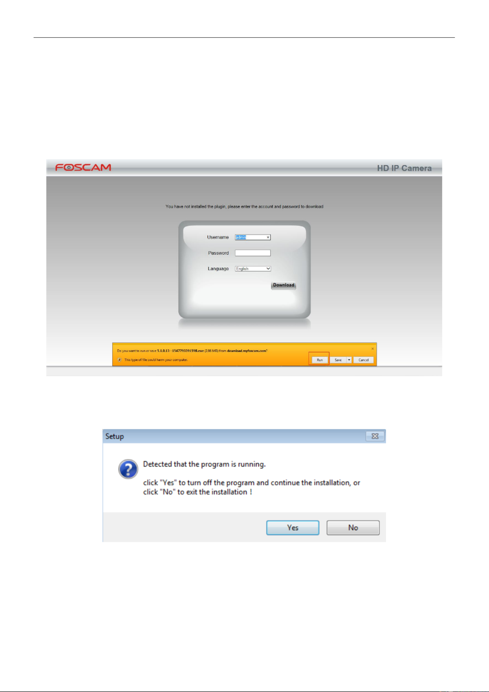
Step 1: User IE browser to log in the camera for the rst time, it will prompt to ask your install the plugin on the
bottom of IE browser.
Step 2: Click to continue the installation of the .exe plugin. Install
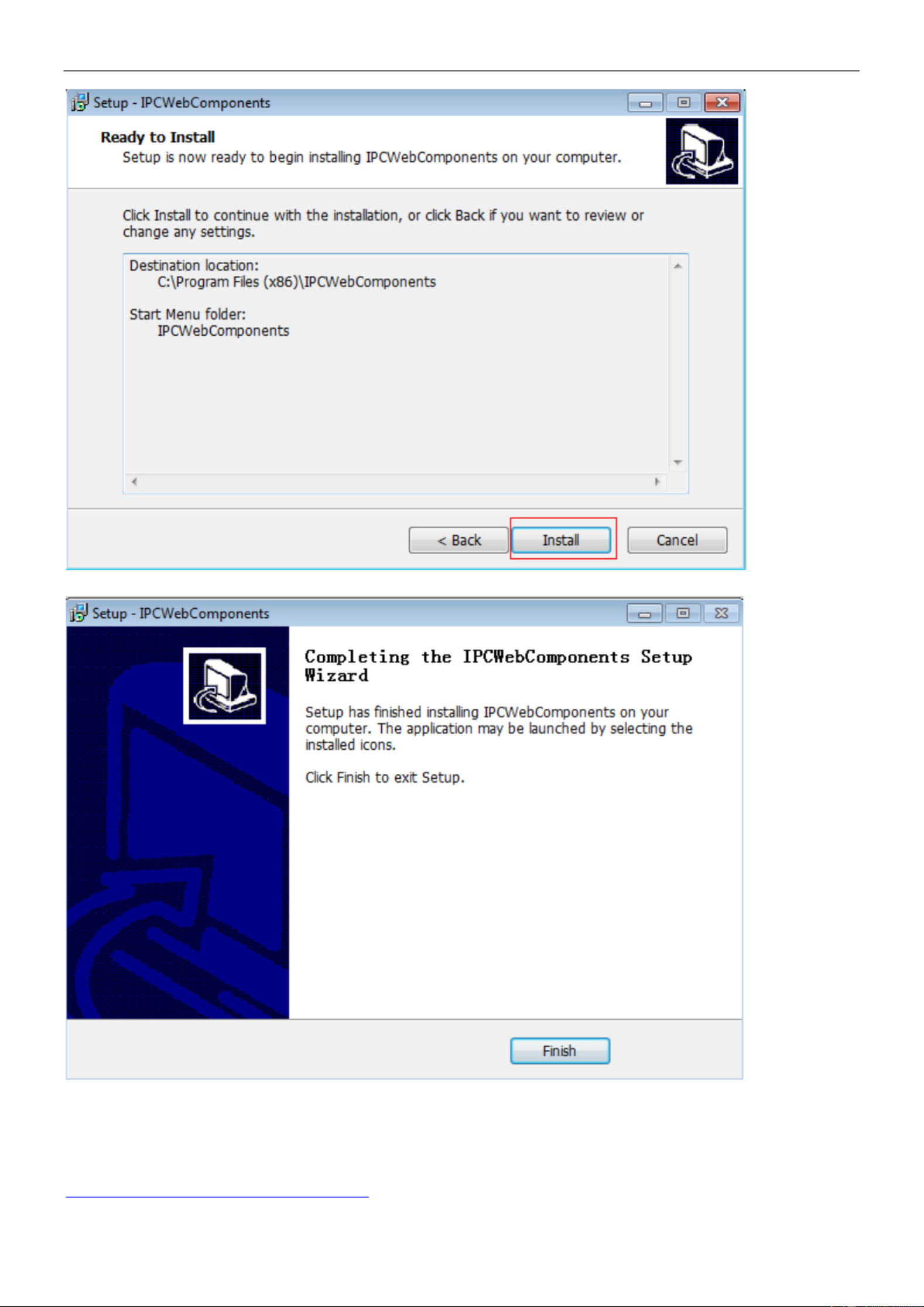
Step 3: Follow the Setup Wizard to nished installing the plugin
Note: When starting to install the plug-in, it will force to close the IE browser. Please click Yes to close the IE browser
rstly.
And click Next to follow the setup wizard.

55

56
57
Step 4: Click and reboot IE browser to log in the camera. Finish
Note, for Safari on MAC OSX it ll show a link ’ “Plugins are not found, click me to download just above login windows ”
of the camera. Please click it to download plugin and follow wizard to install. See this link for help if after installed
plugin but still cannot login camera:
http://www.foscam.com/faqs/view.html?id=14

58
6.1.3 Unable to connect to router wirelessly
After setup wireless configuration, and input the wireless password correctly, save the settings. Normally, after
you disconnect the Ethernet cable, wait for few minutes camera will show up again in Equipment Search Tool
(or show up in router’s DHCP client list/LAN list) with a new IP address. That indicates your camera’s
connected wirelessly.
If not, please follow below steps to help camera connect wirelessly.
Step1: Please make sure wireless signal is strong enough to connect with.
(1) Make sure the camera antenna is xed well;
(2) Best to keep the distance between the camera and router in 2~3 meters while setup;
(3) There’s no interference or obstacles from house appliance or walls;
Step2: Please check if the frequency band of the wireless signal is 2.4GHz.
Our cameras only support connecting to 2.4GHz frequency wireless band. If your wireless router is dual band,
that supports two frequency band 2.4GHz and 5GHz.
Please set the 2.4GHz and 5GHz with different SSIDs, and make sure congure camera to connect with the
2.4GHz SSID.
Step3: Please check if your wireless password contains special characters.
Remove special character in SSID and wireless password to have a try.
Step 4: Reboot camera and router to have a check.
If above are all conrmed, power o and on the camera and router may help camera to connect.
Step 5: Please log-in the router and check if the MAC filter feature is enabled.
Camera has wired and wireless MAC, they are different. If your router has wireless MAC filtering turned on, it’ll
block camera to connect. Please turn it off, or add camera’s MACs in the allow list.
Step 6: Please change the wireless channel, and the wireless encryption of router to have a try.
Change channel helps reduce influence from nearby WiFi networks, you can try 3,6,or 11 for example. As for
encryption, suggest use WPA2/PSK AE S.
Step7: At last reset camera to default, and please try re-congure the wireless settings again.
6.1.4 Forgot camera’s user name and password
Camera can be hard reset to default settings, when you forgot camera’s login user name and password. Below
are the steps:
(1) Keep power on camera;
(2) Press and hold reset button of camera for 30 second, till it reboots. Reset button is on bottom, or back, or
end cords of the camera.
(3) Once reset, camera will be restored to default settings. And default username is admin, no password
(leave password blank).

59
6.1.5 How to setup alarm recording to SD card
For the cameras that support SD card, we can save alarm recording on SD card and below are the steps to set
it up:
Step 1: Setup the Motion Detection Settings
Please go to Settings > Alarm > Motion Detection menu.
(1) Click . Enable
(2) Choose Recording for the alarm action.
(3) Set the Detection Area
(4) Set a Schedule.
(5) Click to save the settings. Save
Note:
1) Please DO NOT forget to set the alarm schedule, the alarm schedule is red.
2) Please make sure your camera time is correct.
3) Please DO NOT forget to set the alarm area, the detected area is covered by the red grids. Or for some
models you can setup 3 detection zones in total.
Step 2: Setup the Storage Location
Go to Settings Record > > Storage Location, and set the “Recording Location” to “SD card and click Save.

61
Note:
(1) Please make sure that your sender email supports SMTP;
(2) Please click on before you click on Save Test;
(3) Make sure the test result is success.
(4) After succeed, you will receive a test email in the mailbox of Sender.
Step 2: Setup the Motion Alarm Settings
Please go to Settings > Alarm Motion Detection > menu:
1. Click enable,
2. Choose Send E-mail for the alarm action,
3. set your detection area,
4. Set your schedule.
Do not forget to click on Save after you nish settings.
If there is motion trigger, camera will alarm and you can receive alarm emails.
Note:

62
(1) Please DO NOT forget to set the alarm schedule, the alarm schedule is red.
(2) Please make sure your camera time is correct.
(3) Please DO NOT forget to set the alarm area, the detected area is covered by the red grids. Or for some
models you can setup 3 detection zones in total.
6.1.7 Camera is not displaying image
Camera unable to show live image on web browser cloud be caused by multiple factors.
(1) Plugin is not installed or running properly.
Please install plugin rst, go to IE Browser > Tool Internet Option Security Custom Level ActiveX > > > >
control and Plug-ins Enable. Three options of front should be set to be , The ActiveX programs read by the
computer will be stored. As follows:
Enable: Download unsigned ActiveX controls.
Enable: Initialize and script ActiveX controls not marked as safe.
Enable: Run ActiveX controls and plug-ins.
(2) Low network bandwidth that’s unable to transfer image. Please lower resolution of the camera.
(3) -cut is stuck at night when IR lights are on. In this case, manually turn o and on IR lights a few times. IR
(4) Also, if camera’s firmware is too old that doesn’t support the browser and unable to install plugin will cause
the same issue. Please update firmware of the camera to latest rst.
6.1.8 Unable to connect camera remotely using Foscam app
Foscam P2P cameras allow users to connect camera remotely using Foscam app without extract setup like
port forwarding. When it unable to connect remotely, below tips can help app establish the connection:
(1) Update app and camera’s firmware to latest version,
(2) Power off the camera then power back on,
(3) Delete camera from app then re-add it back, also lower camera’s resolution.
6.1.9 Camera is added by others
When use myfoscam.com cloud or Foscam app, one camera can only be added to one account at the same
time. To solve error “This camera has already been added by another account” when add camera to Foscam
app or cloud, please send a clear photo of camera’s model sticker to Foscam support email
support@foscam.com to unbind it.
More FAQs are available here:
https://www.foscam.com/faqs/index.html
6.2 Default Parameters
Default network parameters

63
IP address: obtain dynamically
Subnet mask: obtain dynamically
Gateway: obtain dynamically
Username and password
Default admin username: admin with a blank password
6.3 Specication
ITEMS
G2 FI9902P FI9912P
Image Sensor
Sensor
High Denition Color CMOS Sensor
Display Resolution
1920 * 1080 (2.0M Pixels)
Min. Illumination
0 Lux (With IR Illuminator)
Lens
Lens Type
Glass Lens
focal length
f:4mm
Aperture
F 2.0
Angle of view
Horizontal: º, Diagonal: 589 10 º
Video
Image Compression
H.264
Image Frame Rate
30fps (60Hz), 25fps (50Hz), downward adjustable
Resolution
1080P (1920 * 1080), 720P (1280 * 720), VGA (640 *
480), QVGA (320 * 240)
Stream
dual stream
Image adjustment
The hue, brightness, contrast, saturation, sharpness are
adjustable
Flip image
ip and mirror
Infrared mode
Automatic or manual
IR range
With 30pcs IR-LED, IR LEDs for IR range up to 20m /
66ft
Audio
Input / Output
External RCA interface for two-way audio
Audio Compression
PCM / G.726
Network
Ethernet
One 10/100Mbps RJ45 port
Wireless Standard
IEEE802.11b / g / n
Data Rate
IEEE802.11b: 11Mbps (Max.);
IEEE802.11g: 54Mbps (Max.);
IEEE802.11n: 150Mbps (Max.).
Frequency bands
2412-2472MHz
Maximum power
18dBm
Wireless Security
WPA, WPA2
Remote Access
P2P
Network Protocol
IP, TCP, UDP, HTTP, HTTPS, SMTP, FTP, DHCP, RTSP,
ONVIF

64
System
Requirements
Operating System
Microsoft Windows 2000/XP, Vista 7,8;
Mac OS
Browser
Microsoft IE8 and above version or compatible browser;
Mozilla Firefox;
Google Chrome;
Apple Safari.
Other Features
Motion Detection
Alarm via E-mail, upload alarm snapshot to FTP
User Accounts
Three levels user role
Firewall
Supports IP Filtering
Reset
Reset button is available
Power
Power Supply
DC 12V / 1.0A
Power Consumption
5 Watts (Max.)
Physical
Dimension (L * W * H)
97 67mm * mm * 64mm / 3.8in * 2.6in * 2.5in
Net Weight
255g / 0.6lb
Environment
Waterproof
IP66
Operating Temperature
- ~ 60 (14 ~ 140 ) 10ºC ºC ºF ºF
Operating Humidity
10% ~ 80% non-condensing
Storage Temperature
- ~ 60 (-4 ~ 140 ) 20ºC ºC ºF ºF
Storage Humidity
0% ~ 90% non-condensing
Certication
FCC, CE, RoHS, WEEE,IP66
ITEMS
G4P G4
Image Sensor
Sensor
High Denition Color CMOS Sensor
Display Resolution
2560*1440 (4.0M Pixels)
Min. Illumination
0 Lux (With IR Illuminator)
Lens
Lens Type
Glass Lens
focal length
f:4mm
Aperture
F 2.0
Angle of view
Horizontal: º, Diagonal: 189 12º
Video
Image Compression
H.264
Image Frame Rate
30fps (60Hz), 25fps (50Hz), downward adjustable
Resolution
2k(2304x1536)
20fps,3MP(1204x1440)25fps,1080P(1920x1080)
25fps,720P(1280 x 720), VGA(640 x 480),QVGA(320 x
240)
Stream
dual stream
Image adjustment
The hue, brightness, contrast, saturation, sharpness are
adjustable
Flip image
ip and mirror
Infrared mode
Automatic or manual
IR range
With 30pcs IR-LED, IR LEDs for IR range up to 20m /

65
66ft
Audio
Input / Output
External RCA interface for two-way audio
Audio Compression
PCM / G.726
Network
Ethernet
One 10/100Mbps RJ45 port
Wireless Standard
IEEE802.11b / g / n
Data Rate
IEEE802.11b: 11Mbps (Max.);
IEEE802.11g: 54Mbps (Max.);
IEEE802.11n: 150Mbps (Max.).
Frequency bands
2412-2472MHz
Maximum power
18dBm
Wireless Security
WPA, WPA2
Remote Access
P2P
Network Protocol
IP, TCP, UDP, HTTP, HTTPS, SMTP, FTP, DHCP, RTSP,
ONVIF
System
Requirements
Operating System
Microsoft Windows 2000/XP, Vista 7,8;
Mac OS
Browser
Microsoft IE8 and above version or compatible browser;
Mozilla Firefox;
Google Chrome;
Apple Safari.
Other Features
Motion Detection
Alarm via E-mail, upload alarm snapshot to FTP
User Accounts
Three levels user role
Firewall
Supports IP Filtering
Reset
Reset button is available
Power
Power Supply
DC 12V / 1.0A
Power Consumption
5 Watts (Max.)
Physical
Dimension (L * W * H)
97 67mm * mm * 64mm / 3.8in * 2.6in * 2.5in
Net Weight
37 835g / 0. lb
Environment
Waterproof
IP66
Operating Temperature
- ~ 60 (14 ~ 140 ) 10ºC ºC ºF ºF
Operating Humidity
10% ~ 80% non-condensing
Storage Temperature
- ~ 60 (-4 ~ 140 ) 20ºC ºC ºF ºF
Storage Humidity
0% ~ 90% non-condensing
Certication
FCC, CE, RoHS, WEEE,IP66
Attention: Power adapter should be used between - ºC ~ , and 20%-90% relative humidity. 20 40ºC
6.4 CE & FCC
Electromagnetic Compatibility (EMC)
FCC Statement
Produkt Specifikationer
| Mærke: | Foscam |
| Kategori: | Overvågningskamera |
| Model: | G4 |
Har du brug for hjælp?
Hvis du har brug for hjælp til Foscam G4 stil et spørgsmål nedenfor, og andre brugere vil svare dig
Overvågningskamera Foscam Manualer

10 December 2024
9 December 2024
4 December 2024
14 Oktober 2024
6 Oktober 2024
4 Oktober 2024
3 Oktober 2024
27 September 2024
3 September 2024
31 August 2024
Overvågningskamera Manualer
- Overvågningskamera Bosch
- Overvågningskamera Denver
- Overvågningskamera Sony
- Overvågningskamera Canon
- Overvågningskamera Netis
- Overvågningskamera Samsung
- Overvågningskamera Panasonic
- Overvågningskamera Extech
- Overvågningskamera Moog
- Overvågningskamera TP-Link
- Overvågningskamera Philips
- Overvågningskamera Vitek
- Overvågningskamera Gigaset
- Overvågningskamera Pioneer
- Overvågningskamera Mitsubishi
- Overvågningskamera Braun
- Overvågningskamera Logitech
- Overvågningskamera Emos
- Overvågningskamera Google
- Overvågningskamera Technaxx
- Overvågningskamera HP
- Overvågningskamera Waeco
- Overvågningskamera Garmin
- Overvågningskamera Sanyo
- Overvågningskamera Grundig
- Overvågningskamera D-Link
- Overvågningskamera Arlo
- Overvågningskamera Motorola
- Overvågningskamera Asus
- Overvågningskamera Toshiba
- Overvågningskamera Pyle
- Overvågningskamera Kodak
- Overvågningskamera Furrion
- Overvågningskamera InFocus
- Overvågningskamera Nedis
- Overvågningskamera Friedland
- Overvågningskamera Abus
- Overvågningskamera Planet
- Overvågningskamera Adj
- Overvågningskamera Hama
- Overvågningskamera Creative
- Overvågningskamera Thomson
- Overvågningskamera Belkin
- Overvågningskamera Edimax
- Overvågningskamera Burg Wächter
- Overvågningskamera Clas Ohlson
- Overvågningskamera DataVideo
- Overvågningskamera Strong
- Overvågningskamera TRENDnet
- Overvågningskamera Smartwares
- Overvågningskamera Trevi
- Overvågningskamera Trust
- Overvågningskamera Laserliner
- Overvågningskamera Blaupunkt
- Overvågningskamera JVC
- Overvågningskamera Honeywell
- Overvågningskamera Uniden
- Overvågningskamera Buffalo
- Overvågningskamera Linksys
- Overvågningskamera Megasat
- Overvågningskamera Cisco
- Overvågningskamera EZVIZ
- Overvågningskamera König
- Overvågningskamera Elro
- Overvågningskamera Gembird
- Overvågningskamera Powerfix
- Overvågningskamera Alpine
- Overvågningskamera Netgear
- Overvågningskamera Maginon
- Overvågningskamera Yale
- Overvågningskamera Withings
- Overvågningskamera Nest
- Overvågningskamera Kerbl
- Overvågningskamera Vtech
- Overvågningskamera Exibel
- Overvågningskamera Genie
- Overvågningskamera Vaddio
- Overvågningskamera Bresser
- Overvågningskamera Western Digital
- Overvågningskamera Anker
- Overvågningskamera Digitus
- Overvågningskamera Zebra
- Overvågningskamera Jensen
- Overvågningskamera Alecto
- Overvågningskamera Flamingo
- Overvågningskamera Rollei
- Overvågningskamera Olympia
- Overvågningskamera Xiaomi
- Overvågningskamera Niceboy
- Overvågningskamera Aiptek
- Overvågningskamera Schneider
- Overvågningskamera B/R/K
- Overvågningskamera Marmitek
- Overvågningskamera Tesla
- Overvågningskamera Imou
- Overvågningskamera Ricoh
- Overvågningskamera Nexxt
- Overvågningskamera Aida
- Overvågningskamera APC
- Overvågningskamera Lorex
- Overvågningskamera Ikan
- Overvågningskamera Velleman
- Overvågningskamera LevelOne
- Overvågningskamera Marshall
- Overvågningskamera FLIR
- Overvågningskamera Perel
- Overvågningskamera Swann
- Overvågningskamera Vivotek
- Overvågningskamera Joblotron
- Overvågningskamera JUNG
- Overvågningskamera ORNO
- Overvågningskamera Binatone
- Overvågningskamera ZyXEL
- Overvågningskamera Fortinet
- Overvågningskamera Netatmo
- Overvågningskamera Tenda
- Overvågningskamera Eufy
- Overvågningskamera Ring
- Overvågningskamera M-e
- Overvågningskamera Overmax
- Overvågningskamera Somfy
- Overvågningskamera Y-cam
- Overvågningskamera Hikvision
- Overvågningskamera Monacor
- Overvågningskamera ION
- Overvågningskamera Raymarine
- Overvågningskamera Ubiquiti Networks
- Overvågningskamera AVerMedia
- Overvågningskamera EnGenius
- Overvågningskamera Reolink
- Overvågningskamera Grandstream
- Overvågningskamera Trebs
- Overvågningskamera EVE
- Overvågningskamera Renkforce
- Overvågningskamera Marshall Electronics
- Overvågningskamera Manhattan
- Overvågningskamera SPC
- Overvågningskamera Caliber
- Overvågningskamera Pentatech
- Overvågningskamera Switel
- Overvågningskamera AVtech
- Overvågningskamera LogiLink
- Overvågningskamera Orion
- Overvågningskamera Eminent
- Overvågningskamera Kramer
- Overvågningskamera QSC
- Overvågningskamera Hanwha
- Overvågningskamera Brilliant
- Overvågningskamera Lanberg
- Overvågningskamera Hive
- Overvågningskamera Siedle
- Overvågningskamera BirdDog
- Overvågningskamera Evolveo
- Overvågningskamera Genius
- Overvågningskamera KJB Security Products
- Overvågningskamera Valueline
- Overvågningskamera Provision-ISR
- Overvågningskamera Quantum
- Overvågningskamera Axis
- Overvågningskamera ACTi
- Overvågningskamera CRUX
- Overvågningskamera Avanti
- Overvågningskamera Vimar
- Overvågningskamera Aluratek
- Overvågningskamera Dahua Technology
- Overvågningskamera Chacon
- Overvågningskamera SereneLife
- Overvågningskamera ZKTeco
- Overvågningskamera AG Neovo
- Overvågningskamera Stabo
- Overvågningskamera EtiamPro
- Overvågningskamera First Alert
- Overvågningskamera Speco Technologies
- Overvågningskamera Boss
- Overvågningskamera Broan
- Overvågningskamera Conceptronic
- Overvågningskamera Avidsen
- Overvågningskamera Crestron
- Overvågningskamera Lindy
- Overvågningskamera Kogan
- Overvågningskamera AVMATRIX
- Overvågningskamera Delta Dore
- Overvågningskamera Promise Technology
- Overvågningskamera Sitecom
- Overvågningskamera DiO
- Overvågningskamera Minox
- Overvågningskamera Intellinet
- Overvågningskamera V-TAC
- Overvågningskamera Qian
- Overvågningskamera August
- Overvågningskamera IDIS
- Overvågningskamera Geovision
- Overvågningskamera Schwaiger
- Overvågningskamera Steren
- Overvågningskamera Elmo
- Overvågningskamera AViPAS
- Overvågningskamera UniView
- Overvågningskamera Equip
- Overvågningskamera Alfatron
- Overvågningskamera REVO
- Overvågningskamera Aqara
- Overvågningskamera Ernitec
- Overvågningskamera Setti+
- Overvågningskamera BZBGear
- Overvågningskamera PTZ Optics
- Overvågningskamera AVer
- Overvågningskamera Ferguson
- Overvågningskamera Moxa
- Overvågningskamera Inovonics
- Overvågningskamera Bea-fon
- Overvågningskamera Profile
- Overvågningskamera WyreStorm
- Overvågningskamera Allnet
- Overvågningskamera Aldi
- Overvågningskamera Airlive
- Overvågningskamera Aritech
- Overvågningskamera ACME
- Overvågningskamera KlikaanKlikuit
- Overvågningskamera Marquant
- Overvågningskamera Ednet
- Overvågningskamera Lumens
- Overvågningskamera Hombli
- Overvågningskamera Naxa
- Overvågningskamera Miniland
- Overvågningskamera Xavax
- Overvågningskamera Gira
- Overvågningskamera Interlogix
- Overvågningskamera DSC
- Overvågningskamera Boyo
- Overvågningskamera Iget
- Overvågningskamera EverFocus
- Overvågningskamera Adesso
- Overvågningskamera Satel
- Overvågningskamera Notifier
- Overvågningskamera Monoprice
- Overvågningskamera Beafon
- Overvågningskamera Chuango
- Overvågningskamera MicroView
- Overvågningskamera ETiger
- Overvågningskamera Videcon
- Overvågningskamera INSTAR
- Overvågningskamera Advantech
- Overvågningskamera Digital Watchdog
- Overvågningskamera Moen
- Overvågningskamera Ganz
- Overvågningskamera MEE Audio
- Overvågningskamera Mobotix
- Overvågningskamera Kwikset
- Overvågningskamera Ikegami
- Overvågningskamera Leviton
- Overvågningskamera Pelco
- Overvågningskamera Approx
- Overvågningskamera ClearOne
- Overvågningskamera Ebode
- Overvågningskamera Oplink
- Overvågningskamera Dorr
- Overvågningskamera Sonic Alert
- Overvågningskamera Linear PRO Access
- Overvågningskamera Summer Infant
- Overvågningskamera SMC
- Overvågningskamera Topica
- Overvågningskamera Iiquu
- Overvågningskamera Verint
- Overvågningskamera Brinno
- Overvågningskamera Rostra
- Overvågningskamera Caddx
- Overvågningskamera Spyclops
- Overvågningskamera EKO
- Overvågningskamera Kguard
- Overvågningskamera Woonveilig
- Overvågningskamera Accsoon
- Overvågningskamera Mobi
- Overvågningskamera Surveon
- Overvågningskamera Hollyland
- Overvågningskamera Epcom
- Overvågningskamera Indexa
- Overvågningskamera Lutec
- Overvågningskamera Whistler
- Overvågningskamera ClearView
- Overvågningskamera VideoComm
- Overvågningskamera IMILAB
- Overvågningskamera 3xLOGIC
- Overvågningskamera Inkovideo
- Overvågningskamera Weldex
- Overvågningskamera SecurityMan
- Overvågningskamera Mach Power
- Overvågningskamera Canyon
- Overvågningskamera CNB Technology
- Overvågningskamera Tapo
- Overvågningskamera Aigis
- Overvågningskamera Exacq
- Overvågningskamera Brickcom
- Overvågningskamera Laxihub
- Overvågningskamera Securetech
- Overvågningskamera EFB Elektronik
- Overvågningskamera NetMedia
- Overvågningskamera Videotec
- Overvågningskamera Illustra
- Overvågningskamera Atlona
- Overvågningskamera Nivian
- Overvågningskamera Arenti
- Overvågningskamera E-bench
- Overvågningskamera Blow
- Overvågningskamera Syscom
- Overvågningskamera Tecno
- Overvågningskamera Night Owl
- Overvågningskamera Guardzilla
- Overvågningskamera Astak
- Overvågningskamera Blink
- Overvågningskamera Milestone Systems
- Overvågningskamera Zavio
- Overvågningskamera Campark
- Overvågningskamera IPX
- Overvågningskamera Dedicated Micros
- Overvågningskamera Hamlet
- Overvågningskamera Annke
- Overvågningskamera Qoltec
- Overvågningskamera Digimerge
- Overvågningskamera Feelworld
- Overvågningskamera Wisenet
- Overvågningskamera Infortrend
- Overvågningskamera Epiphan
- Overvågningskamera HiLook
- Overvågningskamera Compro
- Overvågningskamera Vimtag
- Overvågningskamera Sonoff
- Overvågningskamera Gewiss
- Overvågningskamera Alula
- Overvågningskamera Insteon
- Overvågningskamera Costar
- Overvågningskamera ALC
- Overvågningskamera Security Labs
- Overvågningskamera Comtrend
- Overvågningskamera Seneca
- Overvågningskamera Avigilon
- Overvågningskamera American Dynamics
- Overvågningskamera Vosker
- Overvågningskamera Sentry360
- Overvågningskamera Owltron
- Overvågningskamera Petcube
- Overvågningskamera Enabot
- Overvågningskamera Luis Energy
- Overvågningskamera Sir Gawain
- Overvågningskamera VisorTech
- Overvågningskamera Atlantis Land
- Overvågningskamera B & S Technology
- Overvågningskamera I3International
- Overvågningskamera Ecobee
- Overvågningskamera Turing
- Overvågningskamera Wasserstein
- Overvågningskamera Qolsys
- Overvågningskamera Control4
- Overvågningskamera Milesight
- Overvågningskamera GVI Security
- Overvågningskamera Conbrov
- Overvågningskamera HuddleCamHD
- Overvågningskamera Defender
- Overvågningskamera IOIO
- Overvågningskamera BIRDFY
- Overvågningskamera I-PRO
- Overvågningskamera DVDO
- Overvågningskamera TCP
- Overvågningskamera Bolin Technology
- Overvågningskamera Nextech
- Overvågningskamera Tuya
- Overvågningskamera Bolide
- Overvågningskamera Telycam
- Overvågningskamera Arecont Vision
- Overvågningskamera Schlage
Nyeste Overvågningskamera Manualer
7 April 2025
7 April 2025
6 April 2025
29 Marts 2025
28 Marts 2025
20 Marts 2025
20 Marts 2025
20 Marts 2025
13 Marts 2025
8 Marts 2025