Gigabyte GA-Z97X-SOC FORCE Manual
Læs nedenfor 📖 manual på dansk for Gigabyte GA-Z97X-SOC FORCE (124 sider) i kategorien Bundkort. Denne guide var nyttig for 7 personer og blev bedømt med 4.5 stjerner i gennemsnit af 2 brugere
Side 1/124

GA-Z97X-SOC Force
User's Manual
Rev. 1001
12ME-Z97XSOF-1001R

Motherboard
GA-Z97X-SOC Force
Mar. 31, 2014
Mar. 31, 2014
Motherboard
GA-Z97X-SOC Force

Copyright
© 2014 GIGA-BYTE TECHNOLOGY CO., LTD. All rights reserved.
The trademarks mentioned in this manual are legally registered to their respective owners.
Disclaimer
Information in this manual is protected by copyright laws and is the property of GIGABYTE.
Changes to the specications and features in this manual may be made by GIGABYTE
without prior notice.
No part of this manual may be reproduced, copied, translated, transmitted, or published in any
form or by any means without GIGABYTE's prior written permission.
Documentation Classications
In order to assist in the use of this product, GIGABYTE provides the following types of
documentations:
For quick set-up of the product, read the Quick Installation Guide included with the product.
For detailed product information, carefully read the User's Manual.
For product-related information, check on our website at: http://www.gigabyte.com
Identifying Your Motherboard Revision
The revision number on your motherboard looks like this: "REV: X.X." For example, "REV:
1.0" means the revision of the motherboard is 1.0. Check your motherboard revision before
updating motherboard BIOS, drivers, or when looking for technical information.
Example:

- 4 -
Table of Contents
Box Contents 6 ...................................................................................................................
Optional Items 6 .................................................................................................................
GA-Z97X-SOC Force Motherboard Layout 7 .....................................................................
GA-Z97X-SOC Force Motherboard Block Diagram 8 .........................................................
Chapter 1 Hardware Installation 9 .....................................................................................
1-1 Installation Precautions 9 ....................................................................................
1-2 ProductSpecications .................................................................................... 10
1-3 Installing the CPU and CPU Cooler 14 ...............................................................
1-3-1 Installing the CPU 14 ...................................................................................................
1-3-2 Installing the CPU Cooler 16 .......................................................................................
1-4 Installing the Memory 17 .....................................................................................
1-4-1 DualChannelMemoryConguration .....................................................................17
1-4-2 Installing a Memory 18 ................................................................................................
1-5 Installing an Expansion Card 19 .........................................................................
1-6 Setting up AMD CrossFire™/NVIDIA® SLI™Conguration .............................. 20
1-7 Back Panel Connectors 22 ..................................................................................
1-8 Onboard Buttons, Switches, and LEDs 24 ..........................................................
1-9 Internal Connectors 28 ........................................................................................
Chapter 2 BIOS Setup 39 ..................................................................................................
2-1 Startup Screen 40 ...............................................................................................
2-2 The Main Menu 41 ..............................................................................................
2-3 M.I.T. .............................................................................................................. 44
2-4 System Information 56 ........................................................................................
2-5 BIOS Features 57 ...............................................................................................
2-6 Peripherals ..................................................................................................... 61
2-7 Power Management 64 .......................................................................................
2-8 Save & Exit 66 .....................................................................................................
Chapter3 ConguringSATAHardDrive(s) ................................................................... 67
3-1 ConguringSATAControllers ......................................................................... 67
3-2 Installing the SATA RAID/AHCI Driver and Operating System 79 .......................

- 5 -
Chapter 4 Drivers Installation 83 ........................................................................................
4-1 Chipset Drivers 83 ...............................................................................................
4-2 Application Software 84 ......................................................................................
4-3 Information ..................................................................................................... 84
Chapter 5 Unique Features 85 ...........................................................................................
5-1 BIOS Update Utilities 85 .....................................................................................
5-1-1 Updating the BIOS with the Q-Flash Utility 85 .............................................................
5-1-2 Updating the BIOS with the @BIOS Utility 88 .............................................................
5-2 APP Center 89 ....................................................................................................
5-2-1 EasyTune................................................................................................................90
5-2-2 System Information Viewer 91 .....................................................................................
5-2-3 EZ Setup 92 .................................................................................................................
5-2-4 Fast Boot 97 ................................................................................................................
5-2-5 Smart TimeLock......................................................................................................98
5-2-6 Smart Recovery 2 99 ...................................................................................................
5-2-7 USB Blocker 101 .........................................................................................................
5-2-8 Smart Switch 102 ........................................................................................................
Chapter 6 Appendix 103 ....................................................................................................
6-1 Qualcomm® Atheros Killer Network Manager 103 ...............................................
6-2 ConguringAudioInputandOutput ............................................................. 104
6-2-1 Conguring2/4/5.1/7.1-ChannelAudio .................................................................104
6-2-2 ConguringS/PDIFOut ........................................................................................106
6-2-3 ConguringMicrophoneRecording ......................................................................107
6-2-4 Using the Sound Recorder 109 ...................................................................................
6-3 Troubleshooting............................................................................................ 110
6-3-1 Frequently Asked Questions .................................................................................110
6-3-2 Troubleshooting Procedure .................................................................................. 111
6-4 Debug LED Codes ....................................................................................... 113
Regulatory Statements ............................................................................................ 117
Contact Us 123 ..............................................................................................................

- 6 -
Box Contents
5GA-Z97X-SOC Force motherboard
5Motherboard driver disk
5User's Manual
5Quick Installation Guide
5Four SATA cables
5I/O Shield
5One 2-Way SLI bridge connector
5One 2-Way CrossFire bridge connector
5Eight voltage measurement cables
5One OC Brace
Optional Items
2-portUSB2.0bracket(PartNo.12CR1-1UB030-6*R)
eSATAbracket(PartNo.12CF1-3SATPW-4*R)
3.5"FrontPanelwith2USB3.0/2.0ports(PartNo.12CR1-FPX582-2*R)
HDMI-to-DVIadapter(PartNo.12CT2-HDMI01-1*R)
COMportcable(PartNo.12CF1-1CM001-3*R)
The box contents above are for reference only and the actual items shall depend on the product package you
obtain. The box contents are subject to change without notice.

- 7 -
GA-Z97X-SOC Force Motherboard Layout
(Note) Fordebugcodeinformation,pleaserefertoChapter6.
CPU_FAN
ATX_12V_2X4
ATX
AUDIO
DDR3_2
DDR3_4
DDR3_3
DDR3_1
BAT
Intel®
Z97
CLR_CMOS
PCIEX16
LGA1150
GA-Z97X-SOC Force
KB_MS_USB3
SYS_FAN2
R_USB
SATA3
CODEC
1
0
RST_SW
MEM_SAFE
F_PANEL
Qualcomm® Atheros
Killer E2201 LAN
VGA
ATX_12V
USB30_LAN
+_
SYS_FAN6
CBAT_SW
3 2
5 4
PCI1
PCIEX4_1
PCIEX1
DVI
SYS_FAN1
CPU_OPT
PCIE_SW
SYS_FAN4
F_USB30F_USB1
SPDIF_O
F_AUDIO
DP_HDMI_SPDIF
OC_PEG
F_USB3
F_USB2
PCIEX8
PCI2
PCIEX4_2
SYS_FAN5
PW_SW
RATIO_DW
RATIO_UP
FREQ_DW
+_
FREQ_UP
GEAR
TURBO
TAG
B_BIOS
BBIOS_LED
MBIOS_LED
M_BIOS
COMA
PCIe to PCI Bridge
DTB
SET_LOCK
SB
BIOS_SW
TGR
CMOS_SW
SYS_FAN3
SATA_EXPRESS
DIMM_SW
Debug LED (Note)
OC_IGNITION
iTE®
Super I/O

- 8 -
GA-Z97X-SOC Force Motherboard Block Diagram
Fordetailedproductinformation/limitation(s),referto"1-2ProductSpecications."
LGA1150
CPU
CPUCLK+/-(100MHz)
Dual BIOS
DDR31600/1333MHz
PCI Express Bus
PCIe CLK
(100MHz)
DMI 2.0
FDI
4 SATA 6Gb/s
LPC Bus
Center/Subwoofer Speaker Out
Line Out
MIC
Line In
S/PDIF Out
Rear Speaker Out
PCIe CLK
(100MHz)
PCI Express Bus
2 PCI Express x4
x8
x8
Switch x16 Switch
2 PCI Express x8
x16
PS/2 KB/Mouse
iTE®
Super I/O
DVI
HDMI
DisplayPort
Intel® Z97
Side Speaker Out
CODEC
COM
2 PCI
PCI Bus
PCI CLK
(33MHz)
PCIe to PCI
Bridge
x1
D-Sub
x1
LAN
RJ45
Qualcomm
® Atheros Killer
E2201 LAN
6 USB 3.0/2.0
8 USB 2.0/1.1
1 SATA Express
2 PCI Express x1
x4x1x1
Switch
or
1 PCI Express x4
2 SATA 6Gb/s
or
Dual Channel Memory
oror
1 PCI Express x16
1 PCI Express x8

- 9 -
Hardware Installation
1-1 Installation Precautions
The motherboard contains numerous delicate electronic circuits and components which can become
damagedasaresultofelectrostaticdischarge(ESD).Priortoinstallation,carefullyreadtheuser's
manual and follow these procedures:
•Prior to installation, make sure the chassis is suitable for the motherboard.
•Prior to installation, do not remove or break motherboard S/N (Serial Number) sticker or
warranty sticker provided by your dealer. These stickers are required for warranty validation.
•Always remove the AC power by unplugging the power cord from the power outlet before
installing or removing the motherboard or other hardware components.
•When connecting hardware components to the internal connectors on the motherboard, make
sure they are connected tightly and securely.
•When handling the motherboard, avoid touching any metal leads or connectors.
•It is best to wear an electrostatic discharge (ESD) wrist strap when handling electronic
components such as a motherboard, CPU or memory. If you do not have an ESD wrist strap,
keepyourhandsdryandrsttouchametalobjecttoeliminatestaticelectricity.
•Prior to installing the motherboard, please have it on top of an antistatic pad or within an
electrostatic shielding container.
•Before unplugging the power supply cable from the motherboard, make sure the power supply
has been turned off.
•Before turning on the power, make sure the power supply voltage has been set according to
the local voltage standard.
•Before using the product, please verify that all cables and power connectors of your hardware
components are connected.
•To prevent damage to the motherboard, do not allow screws to come in contact with the
motherboard circuit or its components.
•Make sure there are no leftover screws or metal components placed on the motherboard or
within the computer casing.
•Do not place the computer system on an uneven surface.
•Do not place the computer system in a high-temperature environment.
•Turning on the computer power during the installation process can lead to damage to system
components as well as physical harm to the user.
•If you are uncertain about any installation steps or have a problem related to the use of the
product,pleaseconsultacertiedcomputertechnician.
Chapter 1 Hardware Installation

- 10 -
Hardware Installation
1-2 ProductSpecications
CPU
Support for Intel® Core™ i7 processors/Intel® Core™ i5 processors/
Intel® Core™ i3 processors/Intel® Pentium® processors/
Intel® Celeron® processors in the LGA1150 package
(GotoGIGABYTE'swebsiteforthelatestCPUsupportlist.)
L3 cache varies with CPU
Chipset
Intel® Z97 Express Chipset
Memory
4 x DDR3 DIMM sockets supporting up to 32 GB of system memory
* DuetoaWindows32-bitoperatingsystem limitation,when more than4GB of
physicalmemoryisinstalled,theactualmemorysize displayedwill belessthan
thesizeofthephysicalmemoryinstalled.
Dual channel memory architecture
SupportforDDR31600/1333MHzmemorymodules
Support for non-ECC memory modules
SupportforExtremeMemoryProle(XMP)memorymodules
(Go toGIGABYTE'swebsitefor the latest supportedmemory speeds and
memorymodules.)
Onboard
Graphics
Integrated Graphics Processor:
- 1xD-Subport,supportingamaximumresolutionof1920x1200@60Hz
- 1 x DVI-D port, supporting a maximum resolution of 1920x1200@60Hz
* TheDVI-DportdoesnotsupportD-Subconnectionbyadapter.
- 1xHDMIport,supportingamaximumresolutionof4096x2160@24Hzor
2560x1600@60Hz
* SupportforHDMI1.4aversion.
- 1xDisplayPort,supportingamaximumresolutionof4096x2160@24Hzor
3840x2160@60Hz
* SupportforDisplayPort1.2version.
- Support for up to 3 displays at the same time
- Maximum shared memory of 1 GB
Audio
Realtek® ALC1150 codec
HighDenitionAudio
2/4/5.1/7.1-channel
Support for S/PDIF Out
LAN
Qualcomm®AtherosKillerE2201chip(10/100/1000Mbit)
Expansion Slots
1xPCIExpressx16slot,runningatx16(PCIEX16)
* Foroptimumperformance,ifonlyonePCIExpressgraphicscardistobeinstalled,
be sure to install it in the PCIEX16 slot.
1xPCIExpressx16slot,runningatx8(PCIEX8)
* ThePCIEX8slotsharesbandwidthwiththePCIEX16slot.WhenthePCIEX8slot
is populated, the PCIEX16 slot will operate at up to p10-x8 mode.
2xPCIExpressx16slots,runningatx4(PCIEX4_1 PCIEX4_2),
* ThePCIEX4_1slotsharesbandwidthwiththePCIEX8andPCIEX16slots.When
the PCIEX4_1 slot is populated, the PCIEX16 slot will operate at up to p10-x8 mode
and the PCIEX8 will operate at up to p10-x4 mode.

- 12 -
Hardware Installation
Internal
Connectors
1 x CPU BCLK Up button
1 x CPU Ratio Down button
1 x CPU Ratio Up button
1 x Memory Safe button
1 x Settings Lock button
1 x Direct to BIOS button
1 x OC DIMM switch
1 x OC PCIe switch
1 x OC Ignition button
1 x Clear Battery button
2 x BIOS switches
1 x onboard voltage measurement module
Back Panel
Connectors
4 x USB 2.0/1.1 ports
4 x USB 3.0/2.0 ports
1 x optical S/PDIF Out connector
1 x D-Sub port
1 x DVI-D port
1 x HDMI port
1 x DisplayPort
1 x PS/2 keyboard/mouse port
1 x RJ-45 port
6xaudiojacks(Center/SubwooferSpeakerOut,RearSpeakerOut,SideSpeaker
Out,LineIn,LineOut,MicIn)
I/O Controller iTE I/O Controller Chip
Hardware
Monitor
System voltage detection
CPU/System/Chipset temperature detection
CPU/CPU OPT/System fan speed detection
CPU/System overheating warning
CPU/CPU OPT/System fan fail warning
CPU/CPU OPT/System fan speed control
* Whetherthefanspeedcontrolfunctionissupportedwilldependonthecooleryou
install.
BIOS 2x128Mbitash
Use of licensed AMI UEFI BIOS
Support for DualBIOS
™
PnP 1.0a, DMI 2.7, SM BIOS 2.7, ACPI 2.0
Unique Features
Support for APP Center
* AvailableapplicationsinAPPCentermaydifferbymotherboardmodel.Supported
functions of each application may also differ depending on motherboard
specications.
- @BIOS
- EasyTune
- EZ Setup
- Fast Boot
- ON/OFF Charge
- Smart TimeLock

- 13 -
Hardware Installation
Unique Features - Smart Recovery 2
- System Information Viewer
- USB Blocker
Support for Q-Flash
Support for Smart Switch
Support for Xpress Install
Bundled
Software
Norton
®
InternetSecurity(OEMversion)
Intel
®
Rapid Start Technology
Intel
®
Smart Connect Technology
Intel
®
Smart Response Technology
Operating
System Support for Windows 8.1/8/7
Form Factor ATX Form Factor; 30.5cm x 24.4cm
* GIGABYTEreservestherighttomakeanychangestotheproductspecicationsandproduct-relatedinformationwithout
prior notice.
* Pleasevisitthe pageonGIGABYTE'swebsitetocheckthesupportedoperatingsystem(s)Support & Downloads\Utility
for the software listed in the "Unique Features" and "Bundled Software" columns.

- 14 -
Hardware Installation
1-3 Installing the CPU and CPU Cooler
Read the following guidelines before you begin to install the CPU:
• Make sure that the motherboard supports the CPU.
(GotoGIGABYTE'swebsiteforthelatestCPUsupportlist.)
• Always turn off the computer and unplug the power cord from the power outlet before installing the
CPU to prevent hardware damage.
• LocatethepinoneoftheCPU.TheCPUcannotbeinsertediforientedincorrectly.(Oryoumay
locatethenotchesonbothsidesoftheCPUandalignmentkeysontheCPUsocket.)
• Apply an even and thin layer of thermal grease on the surface of the CPU.
• Do not turn on the computer if the CPU cooler is not installed, otherwise overheating and damage
of the CPU may occur.
• SettheCPUhostfrequencyinaccordancewiththeCPUspecications.Itisnotrecommended
thatthesystembusfrequencybesetbeyondhardwarespecicationssinceitdoesnotmeetthe
standard requirements for the peripherals. If you wish to set the frequency beyond the standard
specications,pleasedosoaccordingtoyourhardwarespecicationsincludingtheCPU,graphics
card, memory, hard drive, etc.
1-3-1 Installing the CPU
A. Locate the alignment keys on the motherboard CPU socket and the notches on the CPU.
Notch
Alignment KeyAlignment Key
Notch
LGA1150 CPU
LGA1150 CPU Socket
Pin One Corner of the CPU Socket
Triangle Pin One Marking on the CPU

- 15 -
Hardware Installation
B. Follow the steps below to correctly install the CPU into the motherboard CPU socket.
Step 1:
Gently press the CPU socket lever handle down
andawayfromthesocketwithyournger.Then
completely lift the CPU socket lever and the metal
load plate/plastic cover will be lifted as well.
Step 2:
HoldtheCPUwithyourthumbandindexngers.
AligntheCPUpinonemarking(triangle)withthe
pinonecorneroftheCPUsocket(oryoumayalign
theCPUnotcheswiththesocketalignmentkeys)
and gently insert the CPU into position.
Step 4:
Finally, secure the lever under its retention tab to
complete the installation of the CPU.
NOTE:
Hold the CPU socket lever by the handle, not the lever base portion.
• Before installing the CPU, make sure to turn off the computer and unplug the power cord from
the power outlet to prevent damage to the CPU.
• To protect the socket contacts, do not remove the protective plastic cover unless the CPU is
inserted into the CPU socket. Save the cover properly and replace it if the CPU is removed.
Step 3:
Once the CPU is properly inserted, carefully
replace the load plate. When replacing the load
plate, make sure the front end of the load plate
is under the shoulder screw. Then press the CPU
socket lever. The protective plastic cover may
pop off from the load plate during the process of
engagingthelever.Removethecover.(Savethe
cover properly and always replace it when the
CPUisnotinstalled.)

- 16 -
Hardware Installation
1-3-2 Installing the CPU Cooler
Follow the steps below to correctly install the CPU cooler on the motherboard.
Use extreme care when removing the CPU cooler because the thermal grease/tape between the CPU
cooler and CPU may adhere to the CPU. Inadequately removing the CPU cooler may damage the CPU.
Step 1:
Apply an even and thin layer of thermal grease on
the surface of the installed CPU.
Step 3:
Place the cooler atop the CPU, aligning the
four push pins through the pin holes on the
motherboard. Push down on the push pins
diagonally.
Step 4:
You should hear a "click" when pushing down each
push pin. Check that the Male and Female push
pins are joined closely.
(RefertoyourCPUcoolerinstallationmanualfor
instructionsoninstallingthecooler.)
Step 5:
After the installation, check the back of the
motherboard. If the push pin is inserted as the
picture above shows, the installation is complete.
Step 6:
Finally, attach the power connector of the CPU
coolertotheCPUfanheader(CPU_FAN)onthe
motherboard.
Male
Push Pin
Female
Push Pin
The Top
of Female
Push Pin
Direction of
the Arrow Sign
on the Male
Push Pin
Step 2:
Before installing the cooler, note the direction of the
arrow sign onthemalepushpin.(Turningthe
push pin along the direction of arrow is to remove
thecooler,onthecontrary,istoinstall.)
- 17 -
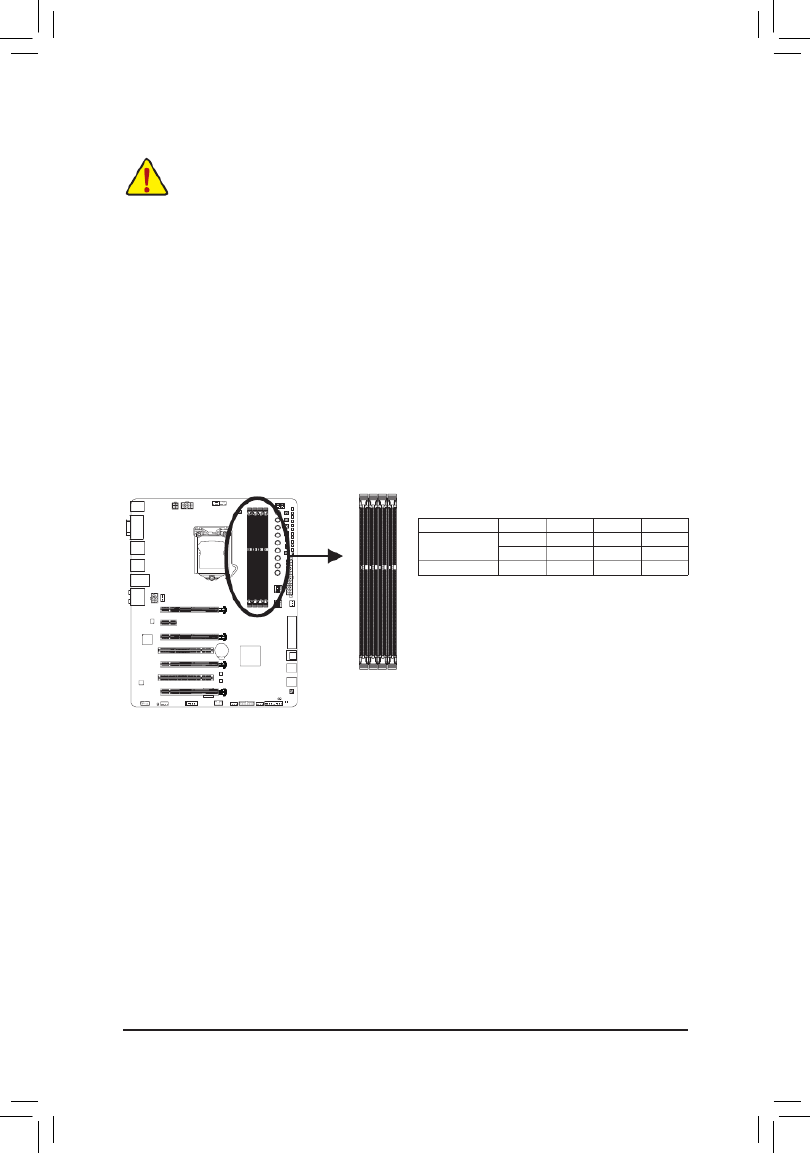
Hardware Installation
1-4 Installing the Memory
Read the following guidelines before you begin to install the memory:
• Make sure that the motherboard supports the memory. It is recommended that memory of the same
capacity, brand, speed, and chips be used.
(GotoGIGABYTE'swebsiteforthelatestsupportedmemoryspeedsandmemorymodules.)
• Always turn off the computer and unplug the power cord from the power outlet before installing the
memory to prevent hardware damage.
• Memory modules have a foolproof design. A memory module can be installed in only one direction.
If you are unable to insert the memory, switch the direction.
DDR3_1
DDR3_2
DDR3_3
DDR3_4
1-4-1 DualChannelMemoryConguration
This motherboard provides four DDR3 memory sockets and supports Dual Channel Technology. After the
memoryisinstalled,theBIOSwillautomaticallydetectthespecicationsandcapacityofthememory.Enabling
Dual Channel memory mode will double the original memory bandwidth.
The four DDR3 memory sockets are divided into two channels and each channel has two memory sockets as
following:
Channel A: DDR3_2, DDR3_4
Channel B: DDR3_1, DDR3_3
DualChannelMemoryCongurationsTable
DDR3_4 DDR3_2 DDR3_3 DDR3_1
Two Modules - - DS/SS - - DS/SS
DS/SS - - DS/SS - -
Four Modules DS/SS DS/SS DS/SS DS/SS
(SS=Single-Sided,DS=Double-Sided,"--"=NoMemory)
Due to CPU limitations, read the following guidelines before installing the memory in Dual Channel mode.
1. Dual Channel mode cannot be enabled if only one DDR3 memory module is installed.
2. When enabling Dual Channel mode with two or four memory modules, it is recommended that memory
of the same capacity, brand, speed, and chips be used and installed in the same colored DDR3
sockets. For optimum performance, when enabling Dual Channel mode with two memory modules,
we recommend that you install them in the DDR3_1 and DDR3_2 sockets.

- 18 -
Hardware Installation
1-4-2 Installing a Memory
Before installing a memory module, make sure to turn off the computer and unplug the power
cord from the power outlet to prevent damage to the memory module. DDR3 and DDR2 DIMMs
are not compatible to each other or DDR DIMMs. Be sure to install DDR3 DIMMs on this
motherboard.
Notch
DDR3 DIMM
ADDR3memorymodulehasanotch,soitcanonlytinonedirection.Followthestepsbelowtocorrectlyinstall
your memory modules in the memory sockets.
Step 1:
Note the orientation of the memory module. Spread the retaining clip
at the right end of the memory socket. Place the memory module on
thesocket.Asindicatedinthepictureontheleft,placeyourngers
on the top edge of the memory, push down on the memory and insert
it vertically into the memory socket.
Step 2:
The clip at the right end of the socket will snap into place when the
memory module is securely inserted.

- 19 -
Hardware Installation
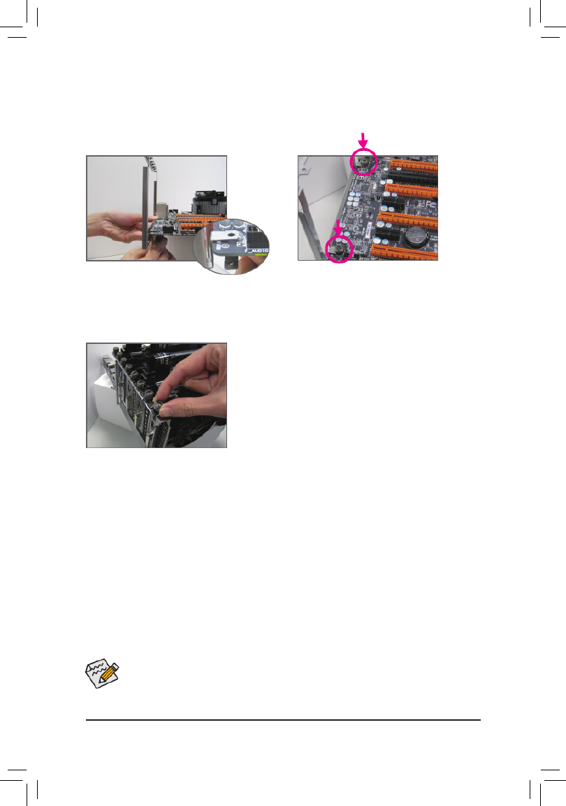
1-5 Installing an Expansion Card
Read the following guidelines before you begin to install an expansion card:
• Make sure the motherboard supports the expansion card. Carefully read the manual that came
with your expansion card.
• Always turn off the computer and unplug the power cord from the power outlet before installing an
expansion card to prevent hardware damage.
Follow the steps below to correctly install your expansion card in the expansion slot.
1. Locate an expansion slot that supports your card. Remove the metal slot cover from the chassis back panel.
2. Align the card with the slot, and press down on the card until it is fully seated in the slot.
3. Make sure the metal contacts on the card are completely inserted into the slot.
4. Secure the card's metal bracket to the chassis back panel with a screw.
5. Afterinstallingallexpansioncards,replacethechassiscover(s).
6. Turn on your computer. If necessary, go to BIOS Setup to make any required BIOS changes for your
expansioncard(s).
7. Install the driver provided with the expansion card in your operating system.
Example: Installing and Removing a PCI Express Graphics Card:
PCI Express p19-x1 Slot
PCI Express x16 Slot
• Installing a Graphics Card:
Gently push down on the top edge of the card until
it is fully inserted into the PCI Express slot. Make
sure the card is securely seated in the slot and
does not rock.
• Removing the Card:
Gently push back on the lever on the slot and then lift the card straight out from
the slot.
PCI Slot

- 20 -
Hardware Installation
1-6 Setting up AMD CrossFire
™/NVIDIA
®
SLI
™Conguration
A. System Requirements
- Windows 8.1/8/7 operating system
- A CrossFire/SLI-supported motherboard with two or more PCI Express p20-x16 slots and correct driver
- CrossFire/SLI-ready graphics cards of identical brand and chip and correct driver
Current GPUs that support 3-Way/4-Way CrossFire technology include the ATI Radeon
™ HD
3800, HD 4800, HD 5800 series, and AMD Radeon
™
HD 6800, HD 6900, HD 7800, and HD
7900 series. For the latest GPU support information, please refer to theAMD officialwebsite.)
CrossFire
(Note1)
/SLI bridge connectors
- Apowersupplywithsufcientpowerisrecommended
(Note2)
(Refertothemanualofyourgraphicscards
forthepowerrequirement)
B. Connecting the Graphics Cards
Step 1:
Observe the steps in "1-5 Installing an Expansion Card" and install CrossFire/SLI graphics cards on the PCI
Expressx16slots.(Tosetupa2-Wayconguration,werecommendinstallingthegraphicscardsinthePCIEX16
andPCIEX8slots.Tosetupa3-Wayconguration,werecommendinstallingthegraphicscardsinthePCIEX16,
PCIEX8,andPCIEX4_1slots.)
Step 2:
Insert the CrossFire
(Note1)
/SLI bridge connectors in the CrossFire/SLI gold edge connectors on top of the cards.
Step 3:
Plug the display cable into the graphics card on the PCIEX16 slot.
C-2. To Enable SLI Function
After installing the graphics card driver in the operating system, go to
the NVIDIA Control Panel. Browse to the CongureSLI,Surround,
Physx Maximize 3D performancescreen and ensure is enabled.
C.ConguringtheGraphicsCardDriver
C-1. To Enable CrossFire Function
After installing the graphics card driver in the operating system,
go to the . Browse to Catalyst Control Center Performance\
AMD CrossFireX
™Conguration and ensure the Enable
CrossFireX
™
check box is selected. If your system have more
than two CrossFire cards, select the GPU combination you
wanttouseandclickApply.(Availablecombinationoptionsare
dependentonthenumberofgraphicscards.)
- 21 -
Hardware Installation
Procedure and driver screen for enabling CrossFire/SLI technology may differ by graphics cards and
driver version. Refer to the manual that came with your graphics cards for more information about
enabling CrossFire/SLI technology.
(Note1) Thebridgeconnectorsmaybeneededornotdependingonyourgraphicscards.
(Note2) Whentwoormoregraphicscardsareinstalled,werecommendthatyouconnectthepowercable
from the power supply to the OC_PEG connetctor to ensure system stability.
(Note3) Thecomponentsreceivedmayvaryinappearancefromtheproductsillustrated.
D. Installing the OC Brace
(Note 3)
OC Brace allows extreme overclockers and system testers to safely install up to four graphics cards in an open
case or test bed without risking PCIe slot damage or preventing cards not showing up in the OS due to poor
contact with PCIe slot. Refer to the following installation instructions:
Step 1:
As shown, align the screw holes on the OC Brace
and back plate with the screw holes near the PCIe
slots on the motherboard.
Step 2:
Fastentwooftheincludedthumbscrews(starting
from the screw hole near the back panel audio
connectors)toholdtheOCBraceinplace.
Step 3:
After installing the graphics cards, use the included
thumb screws to secure the metal brackets of the
graphics cards to the OC Brace.
- 23 -
Hardware Installation
DisplayPort
DisplayPort delivers high quality digital imaging and audio, supporting bi-directional audio transmission.
DisplayPort can support both DPCP and HDCP content protection mechanisms. You can use this port to
connectyourDisplayPort-supportedmonitor.Themaximumsupportedresolutionis4096x2160@24Hz
or3840x2160@60Hz,buttheactualresolutionssupportedaredependentonthemonitorbeingused.
PS/2 Keyboard/Mouse Port
Use this port to connect a PS/2 mouse or keyboard.
USB 3.0/2.0 Port
TheUSB3.0portsupportstheUSB3.0specicationandiscompatibletotheUSB2.0/1.1specication.
UsethisportforUSBdevicessuchasaUSBkeyboard/mouse,USBprinter,USBashdriveandetc.
After installing the DisplayPort device, make sure the default device for sound playback is the
DisplayPortdevice.(Theitemnamemaydifferfromoperatingsystem.RefertotheHDMIsettings
informationonthepreviouspageforthecongurationdialogbox.)
Triple-DisplayCongurationsfortheOnboardGraphics:
Triple-displaycongurationsaresupportedafteryouinstallmotherboarddriversinOS.Onlydual-display
congurationsaresupportedduringtheBIOSSetuporPOSTprocess.
Theaudiojackscanbereconguredtoperformdifferentfunctionsviatheaudiosoftware(supported
functionsforeachjackmayvarybasedonhardwarespecication).OnlymicrophonesstillMUST
be connected to the default Mic in jack. Refer to the instructions on setting up a 2/4/5.1/7.1-channel
audiocongurationinChapter6,"Conguring2/4/5.1/7.1-ChannelAudio."
Center/Subwoofer Speaker Out Jack (Orange)
Usethisaudiojacktoconnectcenter/subwooferspeakersina5.1/7.1-channelaudioconguration.
Rear Speaker Out Jack (Black)
Thisjackcanbeusedtoconnectfrontspeakersina4/5.1/7.1-channelaudioconguration.
Side Speaker Out Jack (Gray)
Usethisaudiojacktoconnectsidespeakersina7.1-channelaudioconguration.
Line In Jack (Blue)
The line out jack. Use this audio jack for line in devices such as an optical drive, walkman, etc.
Line Out Jack (Green)
The line out jack. This jack supports audio amplifying function. For better sound quality, it is recommended
that you connect your headphone/speaker to this jack. Use this audio jack for a headphone or 2-channel
speaker.Thisjackcanbeusedtoconnectfrontspeakersina4/5.1/7.1-channelaudioconguration.
Mic In Jack (Pink)
The Mic in jack. Microphones must be connected to this jack.
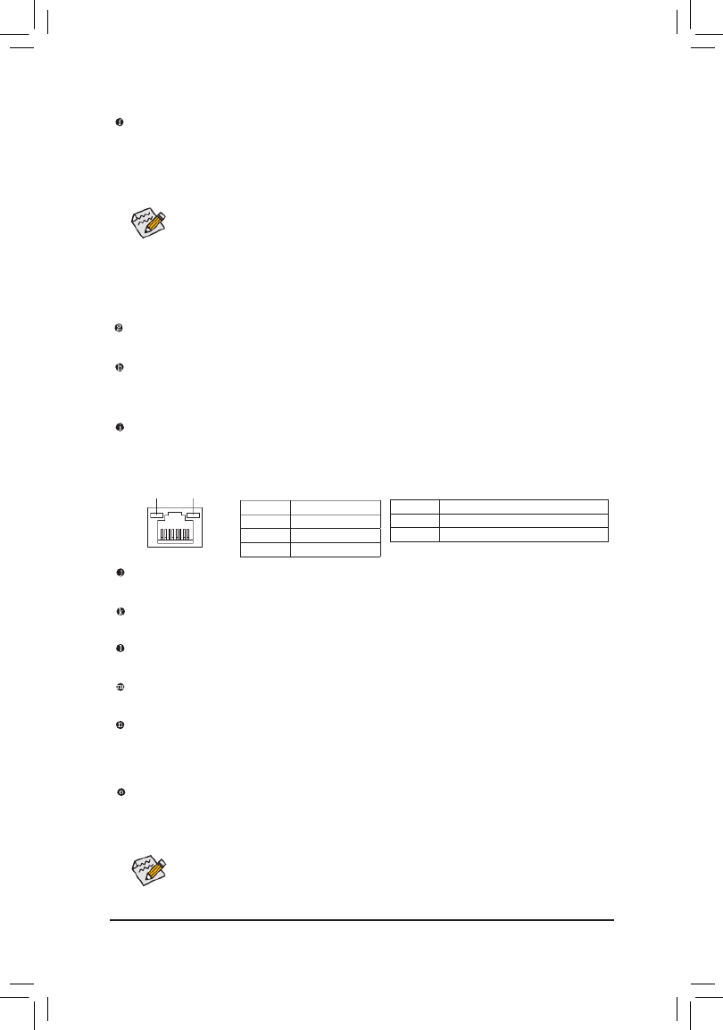
RJ-45 LAN Port
The Gigabit Ethernet LAN port provides Internet connection at up to 1 Gbps data rate. The following
describes the states of the LAN port LEDs.
Activity LED
Connection/
Speed LED
LAN Port
Connection/Speed LED:
State Description
Orange 1 Gbps data rate
Green 100 Mbps data rate
Off 10 Mbps data rate
Activity LED:
State Description
Blinking Data transmission or receiving is occurring
Off No data transmission or receiving is occurring

- 25 -
Hardware Installation
Gear Button
Changes BCLK stepping to 0.1 MHz or 1 MHz.
CPU BCLK Up Button (FREQ_UP):
Raises the CPU base clock.
CPU Ratio Down Button (RATIO_DW):
Lowers the CPU ratio.
CPU Ratio Up Button (RATIO_UP):
Raises the CPU ratio.
OC Buttons
GIGABYTE's unique OC buttons help enthusiasts and overclockers not only get the most performance from
their hardware, but also the absolute most enjoyable OC experience with features like overclocking the CPU in
real-time, automatically loading the most optimized overclocking conguration for the processor and memory,
and loading users' customized settings, etc.
OC PCIe Switch (PCIE_SW)
This switch allows you to manually turn off specic PCI Express slot(s) (except for the PCI Express x1 slot)
without physical removal.
Slot DIP Setting
DIP 1 DIP 2 DIP 3 DIP 4
Disabling PCIEX16 OFF ON ON ON
Disabling PCIEX4_1 ON OFF ON ON
Disabling PCIEX8 ON ON OFF ON
Disabling PCIEX4_2 ON ON ON OFF
PCIE_SW
MEM_SAFE
DTB
SET_LOCK
TGR
OC_IGNITION
GEAR
FREQ_DW
TURBO
RATIO_DW
RATIO_UP
FREQ_UP
CPU BCLK Down Button (FREQ_DW):
Lowers the CPU base clock.
PCIE_SW
OC DIMM Switch (DIMM_SW)
This switch allows you to manually turn off specic memory slots without physical removal. (Note: Using the
OC DIMM switch may impact memory compability.)
Slots DIP Setting
DIP 1 DIP 2 DIP 3 DIP 4
Disabling Channel A
(DDR3_2 & DDR3_4) OFF ON -- --
Disabling Channel B
(DDR3_1 & DDR3_3) ON OFF -- --
DIMM_SW
DIMM_SW
TAG

- 26 -
Hardware Installation
Memory Safe Button (MEM_SAFE):
Pressing the Memory Safe button engages a fail- safe mode that allows the system to boot in a safe memory
conguration,regardlessoftheDDR3DIMMspeedorCASrating.Thesystemwillrebootaftercompletion.(Note:
EngagingMemorySafemayimpactsystemmemoryperformance.)
Beforeusingtheoverclockingbuttons,makesuretoloadtheoptimizeddefaultsinBIOSSetupto
return the BIOS settings to factory defaults.
OC Tag Button (TAG):
Thisbuttonallowsuserstoloadtheircustomizedsettings(usingtheSavetoTagprolecreatedinBIOSSetup)soyou
can apply your custom settings after clearing CMOS.
Settings Lock Button (SET_LOCK):
The GIGABYTE settings lock button allows the system to automatically remember your last successful settings, even
after clearing CMOS. With one touch, the Settings Lock button can quickly revert to the previous good settings; a very
useful tool for overclockers tuning their BIOS to perfection.
OC Turbo Button (TURBO):
PressthisbuttontoloadthemostoptimizedGIGABYTEoverclockingcongurationforyourprocessorandmemory.
OC Ignition Button (OC_IGNITION):
The OC Ignition feature maintains power to your motherboard and connected components while the system
is shut down. After pressing this button, be sure to press the power button to take effect.
OC Trigger Switch (TGR):
This switch allows the overclockers to jump between low and extremely high frequencies in an instant. After remaining at
alowfrequencyduringsystembootandOSoptimization,theoverclockercanthenengagetheTriggerSwitchtoinstantly
hit the target frequency, save their score submission, grab a screen shot, and watch the records tumble.
2:Safefrequency(usingthelowestCPUratio,whichmayvarybyCPU)
1: Target frequency set in BIOS Setup or other overclocking application.
Direct to BIOS Button (DTB):
ThisbuttonhelpsusersmoreeasilytodirectlyentertheBIOSatanytimebeforerebootingthesystem.(Pressingthis
button during the POST process allows you to immediately enter BIOS Setup. Enter BIOS Setup directly on next boot if
thebuttonispressedafterthePOSTprocess.)
1
2
1
2
- 28 -
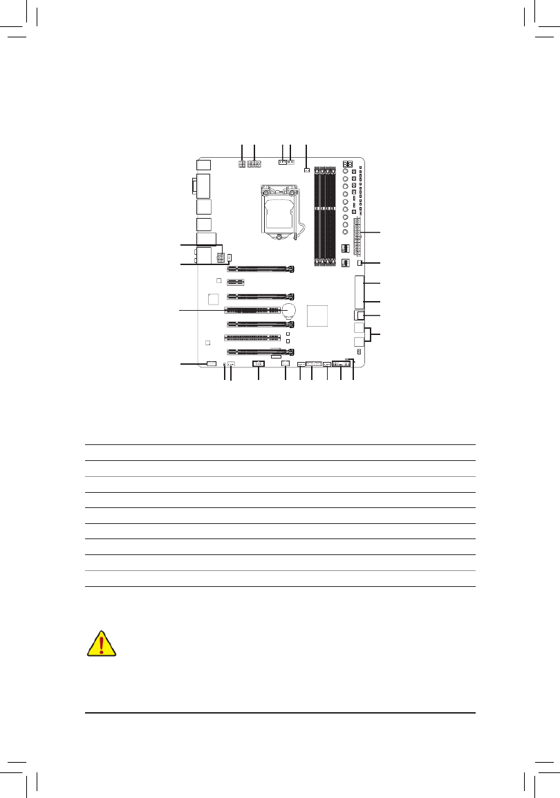
Hardware Installation
1-9 Internal Connectors
Read the following guidelines before connecting external devices:
• First make sure your devices are compliant with the connectors you wish to connect.
• Before installing the devices, be sure to turn off the devices and your computer. Unplug the power
cord from the power outlet to prevent damage to the devices.
• After installing the device and before turning on the computer, make sure the device cable has
been securely attached to the connector on the motherboard.
1) ATX_12V_2X4/ATX_12V
2) ATX
3) OC_PEG
4) CPU_FAN
5) SYS_FAN1/2/3/4/5/6
6) CPU_OPT
7) SATA_EXPRESS
8) SATA3 0/1/2/3/4/5
9) F_AUDIO
10) F_PANEL
11) SPDIF_O
12) F_USB30
13) F_USB1
14) F_USB2/F_USB3
15) COMA
16) BAT
17) CLR_CMOS
2
14
15
9
17
7
511 125
5
13 5
1
3
1 4 6 5
5
16
10
8
8

- 29 -
Hardware Installation
1/2) ATX_12V/ATX_12V_2X4/ATX (2x2, 2x4 12V Power Connectors and 2x12 Main Power
Connector)
With the use of the power connector, the power supply can supply enough stable power to all the components
onthemotherboard.Beforeconnectingthepowerconnector,rstmakesurethepowersupplyisturned
off and all devices are properly installed. The power connector possesses a foolproof design. Connect the
power supply cable to the power connector in the correct orientation.
The 12V power connector mainly supplies power to the CPU. If the 12V power connector is not connected,
the computer will not start.
To meet expansion requirements, it is recommended that a power supply that can withstand high
powerconsumptionbeused(500Worgreater).Ifapowersupplyisusedthatdoesnotprovidethe
required power, the result can lead to an unstable or unbootable system.
131
2412
ATX
ATX_12V_2X4:
Pin No. Denition
1 GND(Onlyfor2x4-pin12V)
2 GND(Onlyfor2x4-pin12V)
3 GND
4 GND
5 +12V(Onlyfor2x4-pin12V)
6 +12V(Onlyfor2x4-pin12V)
7 +12V
8 +12V
ATX:
Pin No. Pin No.Denition Denition
1 3.3V 13 3.3V
2 3.3V 14 -12V
3 GND 15 GND
4 +5V 16 PS_ON(softOn/Off)
5 GND 17 GND
6 +5V 18 GND
7 GND 19 GND
8 Power Good 20 -5V
9 21 +5V5VSB(standby+5V)
10 +12V 22 +5V
11 +12V(Onlyfor2x12-pin
ATX)
23 +5V(Onlyfor2x12-pinATX)
12 3.3V(Onlyfor2x12-pin
ATX)
24 GND(Onlyfor2x12-pin
ATX)
ATX_12V:
Pin No. Denition
1 GND
2 GND
3 +12V
4 +12V
ATX_12V_2X4
8
4
5
1
ATX_12V
2
4
1
3

- 30 -
Hardware Installation
• Be sure to connect fan cables to the fan headers to prevent your CPU and system from
overheating. Overheating may result in damage to the CPU or the system may hang.
• Thesefanheadersarenotcongurationjumperblocks.Donotplaceajumpercapontheheaders.
4/5) CPU_FAN/SYS_FAN1/2/3/4/5/6 (Fan Headers)
Themotherboardhasa4-pinCPUfanheader(CPU_FAN),four4-pin(SYS_FAN1/SYS_FAN2/SYS_FAN3/
SYS_FAN4)andtwo 3-pin(SYS_FAN5/SYS_FAN6)systemfanheaders.Mostfanheaders possessa
foolproof insertion design. When connecting a fan cable, be sure to connect it in the correct orientation
(theblackconnectorwireisthegroundwire).Thespeedcontrolfunctionrequirestheuseofafanwith
fan speed control design. For optimum heat dissipation, it is recommended that a system fan be installed
inside the chassis.
CPU_FAN:
Pin No. Denition
1 GND
2 +12V
3 Sense
4 Speed Control
CPU_FAN
1
1
3) OC PEG (PCIe Power Connector)
The power connector provides auxiliary power to the onboard PCI Express p30-x16 slots. When two or more
graphics cards are installed, we recommend that you connect the 2x3 power cable from the power supply
to this connector to ensure system stability.
Pin No. Denition
1 +12V
2 +12V
3 +12V
4 GND
5 GND
6 GND
SYS_FAN1/2/3/4:
Pin No. Denition
1 GND
2 +12V / Speed Control
3 Sense
4 VCC
SYS_FAN5/6:
Pin No. Denition
1 GND
2 +12V
3 NC
SYS_FAN2/3/4
SYS_FAN6
1
SYS_FAN5
1
_ BS_
3
14
36
1
SYS_FAN1

- 31 -
Hardware Installation
6) CPU_OPT (Water Cooling CPU Fan Header)
The fan header is 4-pin and possesses a foolproof insertion design. When connecting a fan cable, be sure
toconnectitinthecorrectorientation(theblackconnectorwireisthegroundwire).Thespeedcontrol
function requires the use of a fan with fan speed control design.
Pin No. Denition
1 GND
2 +12V/Speed Control
3 Sense
4 VCC
1
_
7) SATA_EXPRESS (SATA Express Connector)
The SATA Express connector supports a single SATA Express device.
SATA Express and SATA3 4/5 connectors can only be used one at a time.

- 32 -
Hardware Installation
8) SATA3 0/1/2/3/4/5 (SATA 6Gb/s Connectors)
The SATA connectors conform to SATA 6Gb/s standard and are compatible with SATA 3Gb/s and SATA
1.5Gb/s standard. Each SATA connector supports a single SATA device. The Intel
®
Chipset supports RAID
0,RAID1,RAID5,andRAID10.RefertoChapter3,"ConguringSATAHardDrive(s),"forinstructionson
conguringaRAIDarray. Pin No. Denition
1 GND
2 TXP
3 TXN
4 GND
5 RXN
6 RXP
7 GND
• ARAID0orRAID1congurationrequiresatleasttwoharddrives.Ifmorethantwoharddrives
are to be used, the total number of hard drives must be an even number.
• ARAID5congurationrequiresatleastthreeharddrives.(Thetotalnumberofharddrivesdoes
nothavetobeanevennumber.)
• ARAID10congurationrequiresfourharddrives.
• To enable hot-plugging for the SATA ports, refer to Chapter 2, "BIOS Setup," "Peripherals\SATA
Conguration,"formoreinformation.
1
0
71
7 1
SATA3
3 2
5 4
9) F_AUDIO (Front Panel Audio Header)
ThefrontpanelaudioheadersupportsIntelHighDenitionaudio(HD)andAC'97audio.Youmayconnect
your chassis front panel audio module to this header. Make sure the wire assignments of the module
connector match the pin assignments of the motherboard header. Incorrect connection between the module
connector and the motherboard header will make the device unable to work or even damage it.
• The front panel audio header supports HD audio by default. If your chassis provides an AC'97
front panel audio module, refer to the instructions on how to activate AC'97 functionality via the
audiosoftwareinChapter6,"Conguring2/4/5.1/7.1-ChannelAudio."
• Audio signals will be present on both of the front and back panel audio connections simultaneously.
Ifyouwanttomutethebackpanelaudio(onlysupportedwhenusinganHDfrontpanelaudio
module),refertoChapter6,"Conguring2/4/5.1/7.1-ChannelAudio."
• Some chassis provide a front panel audio module that has separated connectors on each wire
instead of a single plug. For information about connecting the front panel audio module that has
different wire assignments, please contact the chassis manufacturer.
For HD Front Panel Audio:
For AC'97 Front Panel Audio:
Pin No. Denition
1 MIC2_L
2 GND
3 MIC2_R
4 -ACZ_DET
5 LINE2_R
6 GND
7 FAUDIO_JD
8 No Pin
9 LINE2_L
10 GND
Pin No. Denition
1 MIC
2 GND
3 MIC Power
4 NC
5 LineOut(R)
6 NC
7 NC
8 No Pin
9 LineOut(L)
10 NC
9 1
10 2

- 33 -
Hardware Installation
The front panel design may differ by chassis. A front panel module mainly consists of power switch,
reset switch, power LED, hard drive activity LED, speaker and etc. When connecting your chassis
front panel module to this header, make sure the wire assignments and the pin assignments are
matched correctly.
System Status LED
S0 On
S3/S4/S5 Off
10) F_PANEL (Front Panel Header)
Connect the power switch, reset switch, speaker, chassis intrusion switch/sensor and system status indicator
on the chassis to this header according to the pin assignments below. Note the positive and negative pins
before connecting the cables.
•PW(PowerSwitch,Red):
Connectstothepowerswitchonthechassisfrontpanel.Youmaycongurethewaytoturnoffyour
systemusingthepower switch (refer to Chapter2,"BIOS Setup," "Power Management,"for more
information).
•SPEAK (Speaker,Orange):
Connects to the speaker on the chassis front panel. The system reports system startup status by issuing
a beep code. One single short beep will be heard if no problem is detected at system startup.
•HD (HardDriveActivityLED,Blue):
Connects to the hard drive activity LED on the chassis front panel. The LED is on when the hard drive
is reading or writing data.
•RES (ResetSwitch,Green):
Connects to the reset switch on the chassis front panel. Press the reset switch to restart the computer
ifthecomputerfreezesandfailstoperformanormalrestart.
•CI (ChassisIntrusionHeader,Gray):
Connects to the chassis intrusion switch/sensor on the chassis that can detect if the chassis cover has
been removed. This function requires a chassis with a chassis intrusion switch/sensor.
•PLED/PWR_LED (PowerLED,Yellow/Purple):
Connects to the power status indicator on the chassis front panel. The LED
is on when the system is operating. The LED is off when the system is in S3/
S4sleepstateorpoweredoff(S5).
Power LED
1
2
19
20
CI-
CI+
PWR_LED-
PWR_LED+
PLED-
PW-
SPEAK+
SPEAK-
PLED+
PW+
Power LED
HD-
RES+
HD+
RES-
Hard Drive
Activity LED
Reset
Switch
Power Switch
Chassis Intrusion
Header
PWR_LED-
Speaker

- 34 -
Hardware Installation
1
11) SPDIF_O (S/PDIF Out Header)
ThisheadersupportsdigitalS/PDIFOutandconnectsaS/PDIFdigitalaudiocable(providedbyexpansion
cards)fordigitalaudiooutputfromyourmotherboardtocertainexpansioncardslikegraphicscardsand
sound cards. For example, some graphics cards may require you to use a S/PDIF digital audio cable for
digital audio output from your motherboard to your graphics card if you wish to connect an HDMI display
to the graphics card and have digital audio output from the HDMI display at the same time.
For information about connecting the S/PDIF digital audio cable, carefully read the manual for your
expansion card.
Pin No. Denition
1 SPDIFO
2 GND
Prior to installing the USB front panel, be sure to turn off your computer and unplug the power cord
from the power outlet to prevent damage to the USB front panel.
12) F_USB30 (USB 3.0/2.0 Header)
TheheaderconformstoUSB3.0/2.0specicationandcanprovidetwoUSBports.Forpurchasingthe
optional 3.5" front panel that provides two USB 3.0/2.0 ports, please contact the local dealer.
Pin No. Pin No.Denition Denition
1 VBUS D2+11
2 SSRX1- 12 D2-
3 SSRX1+ 13 GND
4 GND 14 SSTX2+
5 SSTX1- 15 SSTX2-
6 SSTX1+ 16 GND
7 GND 17 SSRX2+
8 D1- 18 SSRX2-
9 D1+ 19 VBUS
10 NC 20 No Pin
10
1120
1
- 36 -
Hardware Installation
15) COMA (Serial Port Header)
The COM header can provide one serial port via an optional COM port cable. For purchasing the optional
COM port cable, please contact the local dealer.
10
9
2
1
Pin No. Denition
1 NDCD-
2 NSIN
3 NSOUT
4 NDTR-
5 GND
6 NDSR-
7 NRTS-
8 NCTS-
9 NRI-
10 No Pin
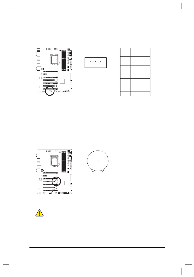
16) BAT (Battery)
Thebatteryprovidespowertokeepthevalues(suchasBIOScongurations,date,andtimeinformation)
in the CMOS when the computer is turned off. Replace the battery when the battery voltage drops to a low
level, or the CMOS values may not be accurate or may be lost.
You may clear the CMOS values by removing the battery:
1. Turn off your computer and unplug the power cord.
2. Gently remove the battery from the battery holder and wait for one minute.
(Oruseametalobjectlikeascrewdrivertotouchthepositiveandnegative
terminalsofthebatteryholder,makingthemshortfor5seconds.)
3. Replace the battery.
4. Plug in the power cord and restart your computer.
•Always turn off your computer and unplug the power cord before replacing the battery.
•Replace the battery with an equivalent one. Danger of explosion if the battery is replaced with
an incorrect model.
•Contact the place of purchase or local dealer if you are not able to replace the battery by yourself
or uncertain about the battery model.
•Wheninstallingthebattery,notetheorientationofthepositiveside(+)andthenegativeside(-)
ofthebattery(thepositivesideshouldfaceup).
•Used batteries must be handled in accordance with local environmental regulations.
- 37 -
Hardware Installation
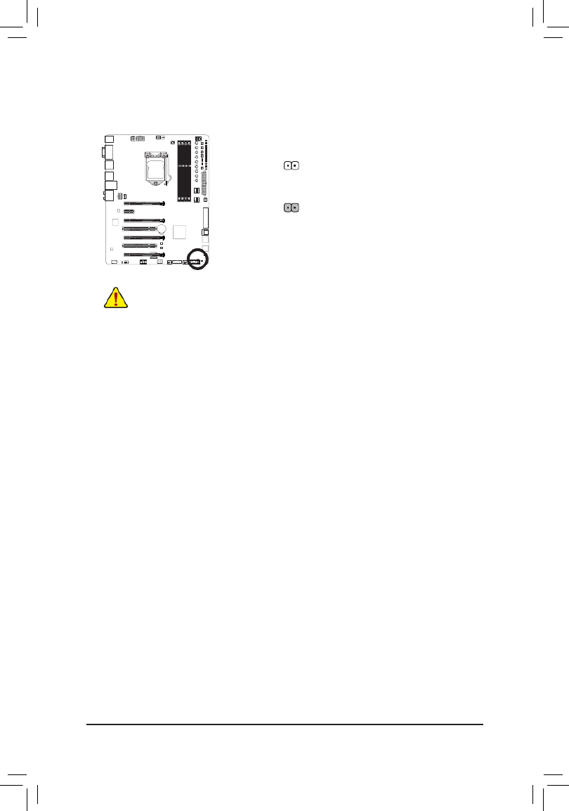
17) CLR_CMOS (Clear CMOS Jumper)
UsethisjumpertocleartheBIOScongurationandresettheCMOSvaluestofactorydefaults.Toclear
the CMOS values, use a metal object like a screwdriver to touch the two pins for a few seconds.
•Always turn off your computer and unplug the power cord from the power outlet before clearing
the CMOS values.
•Aftersystemrestart,gotoBIOSSetuptoloadfactorydefaults(selectLoadOptimizedDefaults)or
manuallyconguretheBIOSsettings(refertoChapter2,"BIOSSetup,"forBIOScongurations).
Open: Normal
Short: Clear CMOS Values

- 38 -
Hardware Installation

- 39 -
BIOS Setup
BIOS (Basic Input and Output System) records hardware parameters of the system in the CMOS on the
motherboard.ItsmajorfunctionsincludeconductingthePower-OnSelf-Test(POST)duringsystemstartup,
saving system parameters and loading operating system, etc. BIOS includes a BIOS Setup program that allows
theusertomodifybasicsystemcongurationsettingsortoactivatecertainsystemfeatures.
When the power is turned off, the battery on the motherboard supplies the necessary power to the CMOS to
keepthecongurationvaluesintheCMOS.
To access the BIOS Setup program, press the <Delete> key during the POST when the power is turned on.
To upgrade the BIOS, use either the GIGABYTE Q-Flash or @BIOS utility.
•Q-Flash allows the user to quickly and easily upgrade or back up BIOS without entering the operating system.
•@BIOS is a Windows-based utility that searches and downloads the latest version of BIOS from the Internet
and updates the BIOS.
For instructions on using the Q-Flash and @BIOS utilities, refer to Chapter 5, "BIOS Update Utilities."
Chapter 2 BIOS Setup
•BecauseBIOS ashingis potentiallyrisky, ifyoudo notencounter problemsusingthecurrent
versionof BIOS,itis recommendedthat younotash theBIOS.To ashtheBIOS, doitwith
caution.InadequateBIOSashingmayresultinsystemmalfunction.
•Itisrecommendedthatyounotalterthedefaultsettings(unlessyouneedto)topreventsystem
instability or other unexpected results. Inadequately altering the settings may result in system's
failure to boot. If this occurs, try to clear the CMOS values and reset the board to default values.
(Refertothe"LoadOptimizedDefaults"sectioninthischapterorintroductionsofthebatteryorthe
clearCMOSjumper/buttoninChapter1forhowtocleartheCMOSvalues.)

BIOS Setup
- 40 -
2-1 Startup Screen
The following startup Logo screen will appear when the computer boots.
Function Keys:
<DEL>: BIOS SETUP\Q-FLASH
Press the <Delete> key to enter BIOS Setup or to access the Q-Flash utility in BIOS Setup.
<F9>: SYSTEM INFORMATION
Press the <F9> key to display your system information.
<F12>: BOOT MENU
BootMenuallowsyoutosettherstbootdevicewithoutenteringBIOSSetup.InBootMenu,usetheup
arrow key < > or the down arrow key <h i>toselecttherstbootdevice,thenpress<Enter>toaccept.
The system will boot from the device immediately.
Note: The setting in Boot Menu is effective for one time only. After system restart, the device boot order
will still be based on BIOS Setup settings.
<END>: Q-FLASH
Pressthe<End>keytoaccesstheQ-FlashutilitydirectlywithouthavingtoenterBIOSSetuprst.
Function Keys

- 41 -
BIOS Setup
2-2 The Main Menu
A. Startup Guide (Default)
TheStartupGuidescreensimpliesconventionalcomplicatedBIOSsetupmenusandpresentsonlythemost
frequentlyusedoptionsintheeasy-to-useinterface.Ithelpsrst-timeuserstoperformbasicsystemsetups
more quickly and easily.
B. ST Mode (Smart Tweak Mode)
Differing from traditional UEFI interface, the ST Mode provides a fancy and user-friendly BIOS environment
where users can easily point and click through various settings and make adjustments for optimum performance.
InSTMode,youcanuseyourmousetomovethroughtheoptionmenusforquickcongurationorpress<F2>
to switch to the traditional BIOS Setup screen.
•When the system is not stable as usual, select the item to set your Load Optimized Defaults
system to its defaults.
•The BIOS Setup menus described in this chapter are for reference only and may differ by BIOS
version.
BIOS Setup
- 42 -
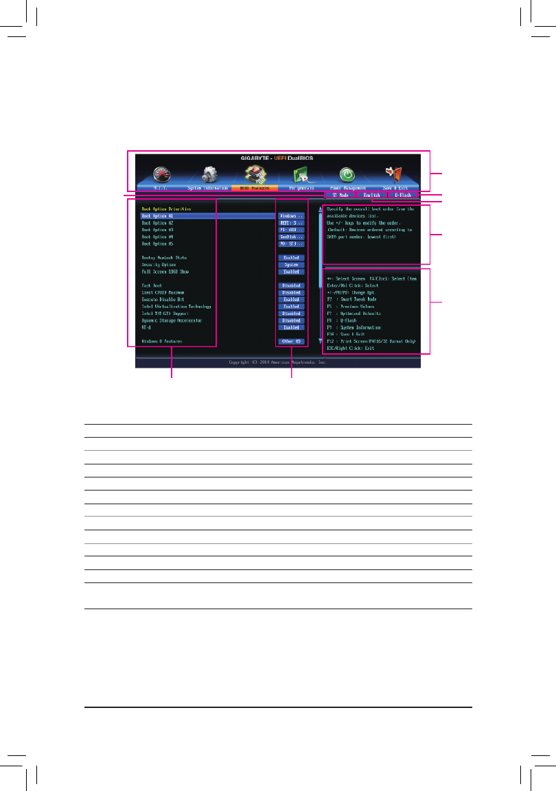
Classic Setup Function Keys
<f><g> Move the selection bar to select a setup menu
<h><i>Movetheselectionbartoselectancongurationitemonamenu
<Enter> Execute command or enter a menu
<+>/<Page Up> Increase the numeric value or make changes
<->/<Page Down> Decrease the numeric value or make changes
<F2> Switch to ST Mode or Startup Guide screen.
<F5> Restore the previous BIOS settings for the current submenus
<F7> LoadtheOptimizedBIOSdefaultsettingsforthecurrentsubmenus
<F8> Access the Q-Flash utility
<F9> Display system information
<F10> Save all the changes and exit the BIOS Setup program
<F12> Capture the current screen as an image and save it to your USB drive
<Esc> Main Menu: Exit the BIOS Setup program
Submenus: Exit current submenu
C. Classic Setup
Classic Setup is the conventional BIOS Setup interface where you can press the arrow keys on your keyboard
to move among the items and press <Enter> to accept or enter a sub-menu. Or you can use your mouse to
select the item you want.
(Sample BIOS Version: F1k)
Setup Menus
Function Keys
Help
Enter Q-Flash
Select Default
Language
CongurationItems Current Settings
Switch to
ST Mode

- 43 -
BIOS Setup
BIOS Setup Menus
M.I.T.
Usethismenutoconguretheclock,frequency,andvoltagesofyourCPUandmemory,etc.Orcheckthe
system/CPU temperatures, voltages, and fan speeds.
System Information
UsethismenutocongurethedefaultlanguageusedbytheBIOSandsystemtimeanddate.
BIOS Features
UsethismenutocongurethedevicebootorderandadvancedfeaturesavailableontheCPU.
Peripherals
Usethismenutocongureallperipheraldevices,suchasSATA,USB,integratedaudio,andintegrated
LAN, etc.
Power Management
Usethismenutocongureallthepower-savingfunctions.
Save & Exit
Save all the changes made in the BIOS Setup program to the CMOS and exit BIOS Setup. You can save
thecurrentBIOSsettingstoaproleorloadoptimizeddefaultsforoptimal-performancesystemoperations.

BIOS Setup
- 44 -
2-3 M.I.T.
Whether the system will work stably with the overclock/overvoltage settings you made is dependent
onyouroverallsystemcongurations.Incorrectlydoingoverclock/overvoltagemayresultindamage
to CPU, chipset, or memory and reduce the useful life of these components. This page is for advanced
users only and we recommend you not to alter the default settings to prevent system instability or
otherunexpectedresults.(Inadequatelyalteringthesettingsmayresultinsystem'sfailuretoboot.If
thisoccurs,cleartheCMOSvaluesandresettheboardtodefaultvalues.)
This section provides information on the BIOS version, CPU base clock, CPU frequency, memory frequency,
totalmemorysize,CPUtemperature,Vcore,andmemoryvoltage.
Produkt Specifikationer
| Mærke: | Gigabyte |
| Kategori: | Bundkort |
| Model: | GA-Z97X-SOC FORCE |
Har du brug for hjælp?
Hvis du har brug for hjælp til Gigabyte GA-Z97X-SOC FORCE stil et spørgsmål nedenfor, og andre brugere vil svare dig
Bundkort Gigabyte Manualer

14 Januar 2025
12 Januar 2025
11 Januar 2025
11 Januar 2025
11 Januar 2025
11 Januar 2025
8 Januar 2025
8 Januar 2025
8 Januar 2025
8 Januar 2025
Bundkort Manualer
- Bundkort Asus
- Bundkort Asrock
- Bundkort MSI
- Bundkort NZXT
- Bundkort ECS
- Bundkort Sapphire
- Bundkort Intel
- Bundkort Sharkoon
- Bundkort Supermicro
- Bundkort Biostar
- Bundkort Evga
- Bundkort Foxconn
- Bundkort Advantech
- Bundkort Elitegroup
- Bundkort EPoX
- Bundkort AOpen
- Bundkort Raspberry Pi
Nyeste Bundkort Manualer

27 Marts 2025

6 Marts 2025
15 Februar 2025

15 Februar 2025
15 Februar 2025
15 Februar 2025
15 Februar 2025
15 Februar 2025
15 Februar 2025
12 Februar 2025