GW Instek GDS-310 Manual
GW Instek
Ikke kategoriseret
GDS-310
Læs nedenfor 📖 manual på dansk for GW Instek GDS-310 (188 sider) i kategorien Ikke kategoriseret. Denne guide var nyttig for 12 personer og blev bedømt med 4.6 stjerner i gennemsnit af 6.5 brugere
Side 1/188

USER MANUAL

Good Will Instrument Co., Ltd.
No. 7-1, Jhongsing Rd., Tucheng Dist., New Taipei City 236, Taiwan.
.
.
..

This chapter will allow you to quickly set up a
GDS-200 or GDS-300 ries oscilloscope and run se
over the basic operation and features.
Before you can get started, you will need to check
the package contents (standard accessories, page
14). After the contents are checked the Overview
section will describe all the major features and
functions of the oscilloscopes in the -200 and GDS
GDS-300 series. The Appearance section will go
over the front, rear and side panels of the
instrument. The Display Overview will give a
brief introduction to the display and how the
display changes depending on the current
function, orientation or mode. Lastly the Getting
Started section will explain how to turn on the
instrument, explain how to set up the instrument,
and go over the gestures and operating
conventions that are used with the capacitive
touch panel on the unit.
Series Lineup ............................................................................................................ 12
Main Features ........................................................................................................... 12

Accessories ................................................................................................................ 1
GDS-200/300 Front Panel ..................................................................................... 15
Rear Panel ................................................................................................................. 1
Interface Panel .......................................................................................................... 1
BNC Panel ................................................................................................................ 2
Display Overview ..................................................................................................... 21
Horizontal ................................................................................................... 21
Vertical ......................................................................................................... 22
How to Use the Touch Interface ........................................................................... 25
Help Menu ................................................................................................................ 2
Power Up .................................................................................................................. 3
USB Driver Installation .......................................................................................... 31
Tilting the Stand ....................................................................................................... 32
Setting the System Date & Time ........................................................................... 33
Setting the Language ............................................................................................... 34
Switching Horizontal and Vertical View ...............................................................34
Compensating a Probe ............................................................................................ 34

GDS-200 & GDS-300 Series User Manual
12
12
12
1212
GDS- and GDS-300 Series Overview 200
Series Lineup
There are 6 models in the series, divided DSO bandwidth DSO by ,
memory depth DMM digit resolution and the DMM temperature ,
function.
Model name
Bandwidth
Memory
depth
DMM
Resolution
Temperature
measureme nt
GDS-207
70MHz
1M points per
channel
3½
No
GDS-210
100MHz
GDS- 220
200MHz
GDS-307
70MHz
5M points per
channel
4½
Yes
GDS-310
100MHz
GDS- 320
200MHz
Note: Throughout the user manual, when we are referring to any of
the models generically, we will write “GDS”, “GDS 200” or “GDS- -
300”, unless explicitly stated otherwise.
Main Features
Performance
1 G Sa/s sampling rate max
70/100/200MHz bandwidth
Acquisition memory: 5Mpts for GDS-300 series;
1Mpts for GDS-200 seri es
Max 300Vrms (CAT II, DSO); 600V (CAT II) or
300V (CAT III) for DMM
30,000 Waveforms can be replayed

Simultaneous DMM and DSO operation
Portrait and landscape modes
Large 800 x 480 TFT panel and capacitive touch
panel
7.4V/6100mAH battery for up to 4 hours
operation
Support for differential probes
Handy APPs EE calculator, Resistance –
calculator, Attenuation calculator
Shielded BNC terminals
DSO Features
X-Y mode
Go/No Go
36 automatic measurement functions
Trend plot
Edge, Alt, Video and Pulse trigger functions
FFT, FFTrms, +, -, /, * math functions
Replay function
DMM Features
50,000 counts
DCV, DCA, ACV, ACA, R, Diode, Continuity,
Temperature
Fuse protection for the current ports
Mini-B USB device port


VW
COMA mA
Digital Storage Oscilloscope
200 MHz 1GSa/s
FUSED
10A MAX
FUSED
CAT II600mA MAX 600V
CAT III 300V
VW
Color LCD screen, 800 x 480, capacitive touch.
The interface panel holds a number of different
interfaces such as the input power socket, USB
device port and the options power port. See page
18 for details.

GDS-200 & GDS-300 Series User Manual
18
18
18
1818
Interface Panel
Power input
for options
Calibration
output
Power
switch
Internal use ports
(restricted access)
USB device port
12V input port
Power Switch
Power switch to turn the unit on or
off.
DC input. This port is used for
charging the internal lithium
battery. Accepts power from the
supplied AC-DC power adapter.
Input Voltage: 10.5V - 13.5V
Input Current: At least 3.5A.
USB Device Port
Mini-B USB device port. This port is
used access the internal 120MB
flash memory. When connected to a
PC, the GDS-200/300 will be
recognized as an external hard disk.
Calibration Port
The calibration port is used to
output a 2Vpk-pk 1kHz square
wave for probe calibration
purposes.
Internal Use Port
This panel houses two ports that are
for internal use only. Use of these
ports are restricted and not for end-
user use.

GETTING STARTED
19
19
19
19 19
This port supplies power for
optional accessories such as the
differential probe option (GW part
number: -040D GDP
Voltage output: 5V
Current output: 250mA

GDS-200 & GDS-300 Series User Manual
20
20
20
2020
MW16.5pF
300V rms MAX.
1
1 2
CAT 300V
Channel 1 and channel 2 BNC inputs.
Input impedance: 1MΩ
Input Capacitance: 16 .5pF
Max voltage: 300V max (CAT II)
The tapped hole is used to secure the differential
probe option to the GDS-200/300. See the
differential probe manual for details.


Displays the triggered signal frequency.
Indicates the trigger state:
Trig’d (triggered)
Stop
<2Hz
Displays the date (horizontal only) and time.
See page to set the time. 33
Shows the horizontal position.
Displays the acquisition mode (Sample, Peak
Detect, Average)

Shows the current horizontal scale and
position in relation to the record length.
Tapping anywhere in the title bar will trigger
the drop down menu.
The gesture control menu allows you to
configure whether the touch gestures control
the input waveforms or the cursors. This
menu will also turn the cursor display on or
off.
The channel indicator shows the vertical
position of each active channel.
Selects the trigger input channel and selects
the trigger source.
Shows the vertical scale of each active channel.
Indicates whether any of the reference or math
channels are activated.
Indicates the horizontal scale and the
sampling rate.
Shows and configures the trigger settings.
Shows the automatic measurements. The
automatic measurements can be minimized or
hidden when used in the horizontal mode.
Shows the DMM measurements. When in the
horizontal view the DMM measurements can
be minimized or even hidden.
The Hardcopy key is used as a quick-save key
either for image screenshots, waveforms,
setup files or all of the above.

The R /Stop is used to start/stop un key
acquiring samples. The Forward/Backward
keys step backward/forward through each
consecutively sampled waveform. The Single
key puts the trigger into single mode.
The Autoset function automatically configures
the panel settings to position the input signal
to the best viewing condition.

Unlike other oscilloscopes or digital
multimeters, the GDS-200 and GDS-300 Series
have no physical hardware keys, therefore
operation is completely controlled using the
capacitive touch screen. Using a capacitive
touch screen is a new interface paradigm for
DSOs; the gestures and general user interface is
easier to use and more intuitive than
traditional DSO interfaces. Before you begin to
use these instruments, we highly recommend
you take a few moments to get to know the
basic gestures and interface conventions.
There are a few basic gestures that can be used
to operate the GDS-200/GDS-300. When asked
to perform a gesture throughout the user
manual, you can refer to the gestures below.
Tap / Press
Tap/Press once to
select an item.
The gesture will be
recognized after you
lift your finger off the
display.
Long Press / Tap &
Hold
Press and hold an
item until a sub-
menu system or
secondary option
appears.

Swipe
Horizontally swipe
on the screen.
Scroll
Drag your finger
vertically on the
screen to scroll.
Pinch In
Pinch the screen to
zoom out (make the
waveforms smaller),
or spread your
fingers apart to zoom
in (make the
waveforms larger).
Pinch Out

Drag and drop
Drag an item to an
option and let go*.
*The drag and drop
gesture is usually
used in the
Horizontal, Vertical
or Trigger menu to
manually set a
positional value.

If at any time you are not sure how to use a
particular function, the help icon can be used to
put an overlay on the screen to show the basic
function of each icon.
Tap the title bar on the top of the LCD display
to bring up the Drop Down menu.
Tap on the Utility icon.

Tap on the Help option in the Utility menu.
The help screen overlay is shown on the
display. There are three help screens. Use the
numbered icons to view the , , , ,
corresponding help screen. Use the exit icon
to exit from the help screen.
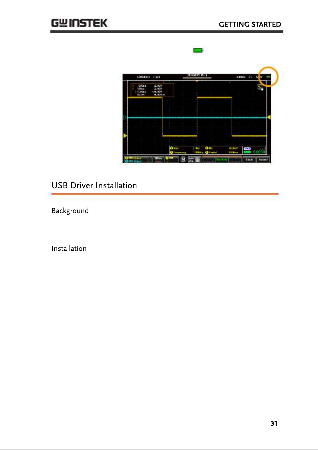
6. The battery indicator is shown on the top
right-hand corner of the main display.
The GDS-200/300 has USB device driver that a
should be installed to get the most out of the
unit.
1. Turn off the GDS-200/300.
2. When the PC is on, connect the USB cable from
the GDS-200/300 to the PC.
3. Turn the GDS-200/300 on.
4. Access the Menu tray by pressing the title bar.
Go to Utility>USB device port and set the
device port to Communication.
5. The PC will now recognize the unit as a new
device and ask to search for the driver .
6. Direct the driver installation wizard to the USB
device driver (dso_vpo.inf) on the User Manual
CD.

7. The GDS-200/300 will now be recognized as a
virtual com port (VCP).
To tilt the stand
horizontally, pull the
catch from the
smaller of the two
stands.
To tilt the stand
vertically, release the
catch from the larger
of the stands.
Produkt Specifikationer
| Mærke: | GW Instek |
| Kategori: | Ikke kategoriseret |
| Model: | GDS-310 |
Har du brug for hjælp?
Hvis du har brug for hjælp til GW Instek GDS-310 stil et spørgsmål nedenfor, og andre brugere vil svare dig
Ikke kategoriseret GW Instek Manualer

1 Februar 2025
1 Februar 2025
14 September 2024
2 September 2024
2 September 2024
2 September 2024
2 September 2024
2 September 2024
2 September 2024
2 September 2024
Ikke kategoriseret Manualer
- Ikke kategoriseret Lindemann
- Ikke kategoriseret Dreambaby
- Ikke kategoriseret Babylonia
- Ikke kategoriseret KRK
- Ikke kategoriseret Wacom
- Ikke kategoriseret Brady
- Ikke kategoriseret Duromax
- Ikke kategoriseret EZ Dupe
- Ikke kategoriseret Schmidt & Bender
- Ikke kategoriseret Tineco
- Ikke kategoriseret Comprehensive
- Ikke kategoriseret Ulanzi
- Ikke kategoriseret Iogear
- Ikke kategoriseret ANDYCINE
- Ikke kategoriseret Heitech
Nyeste Ikke kategoriseret Manualer
10 April 2025

10 April 2025
10 April 2025
10 April 2025
10 April 2025
10 April 2025
10 April 2025
9 April 2025
9 April 2025
9 April 2025