Hanwha SHR-6160 Manual
Hanwha
Overvågningskamera
SHR-6160
Læs nedenfor 📖 manual på dansk for Hanwha SHR-6160 (132 sider) i kategorien Overvågningskamera. Denne guide var nyttig for 11 personer og blev bedømt med 4.5 stjerner i gennemsnit af 2 brugere
Side 1/132

8 Channel/16 Channel DVR
User Manual
SHR-6080/6082/6160/6162
/6163/6164
SHR-7080/7082/7160/7162
SHR-8080/8082/8160/8162
imagine the possibilities
Thanks you for purchasing this Samsung product.
To receive a more complete service, please visit
our website
www.samsungsecurity.com

English _3
OVERVIEW
IMPORTANT SAFETY INSTRUCTIONS
Read these operating instructions carefully before using the unit.
Follow all the safety instructions listed below.
Keep these operating instructions handy for future reference.
Read these instructions.
Keep these instructions.
Heed all warnings.
Follow all instructions.
Do not use this apparatus near water.
Clean only with dry cloth.
Do not block any ventilation openings, Install in accordance with the manufacturer’s instructions.
Do not install near any heat sources such as radiators, heat registers, stoves, or other
apparatus (including amplifi ers) that produce heat.
Do not defeat the safety purpose of the polarized or grounding- type plug. A polarized plug has
two blades with one wider than the other. A grounding type plug has two blades and a third
grounding prong. The wide blade or the third prong are provided for your safety. if the provided
plug does not fi t into your outlet, consult an electrician for replacement of the obsolete outlet.
Protect the power cord from being walked on or pinched particularly at plugs, convenience
receptacles, and the point where they exit from the apparatus.
Only use attachments/accessories specifi ed by the manufacturer.
Use only with the cart, stand, tripod, bracket, or table specifi ed by the
manufacturer, or sold with the apparatus. When a cart is used, use
caution when moving the cart/apparatus combination to avoid injury from
tip-over.
Unplug this apparatus during lightning storms or when unused for long
periods of time.
Refer all servicing to qualifi ed service personnel. Servicing is required when the apparatus has
been damaged in any way, such as power-supply cord or plug is damaged, liquid has been
spilled or objects have fallen into the apparatus, the apparatus has been exposed to rain or
moisture, does not operate normally, or has been dropped.
1)
2)
3)
4)
5)
6)
7)
8)
9)
10)
11)
12)
13)
14)

4_ overview
overview
BEFORE START
This user’s manual provides Information for using DVR such as brief introduction, part names, functions, connection
to other equipment, menu setup, and the like.
You have to keep in mind the following notices :
SAMSUNG retains the copyright on this manual.
This manual cannot be copied without SAMSUNG’s prior written approval.
We are not liable for any or all losses to the product incurred by your use of non-standard product or violation of
instructions mentioned in this manual.
If you want to open the case of your system for checking problems, please consult the expert from the shop
where you bought the product.
Before installing an additional HDD or connecting an external storage device (USB memory or USB HDD) to this
DVR, check the compatibility. Consult your provider for the compatibility list.
Warning
Battery
Exchanging a wrong battery in your product may cause an explosion. Therefore you must use the same type
of battery as the one being used in the product.
The following are the specifi cations of the battery you are using now.
Normal voltage : 3V
Normal capacity : 170mAh
Continuous standard load : 0.2mA
Operating temperature : -20°C ~ +85°C
(-4°F ~ +185°F)
Connect the power cord into a grounded oulet.
The Mains plug is used as a disconnect device and shall stay readily operable at any time.
Batteries shall not be exposed to excessive heat such as sunshine, fi re or the like.
System Shutdown
Turning off the power while the product is in operation, or taking not permitted actions may cause damage to
the hard drive or the product. Also it can cause a dysfunction to the hard disk while using the product.
Please turn off the power using the Power button on the front of your DVR.
After selecting < > in the pop-up menu, you can pull off the power cord.OK
You may want to install a UPS system for safe operation in order to prevent damage caused by an
unexpected power stoppage. (Any questions concerning UPS, consult your UPS retailer.)
Operating Temperature
The guaranteed operating temperature range of this product is 0°C ~ 40°C (32°F ~ 104°F).
This product may not work properly if you run right after a long period of storage at a temperature below the
guaranteed one.
When using the device after a long period of storage at low temperature, place the product at room
temperature for a while and run it.
Especially for the built-in HDD in the product, its guaranteed temperature range is 5°C ~ 55°C (41°F ~ 131°F).
Likewise, the hard drive may not work at a temperature below the guaranteed one.
•
•
•
•
•
❖
•
•
•
•
J
❖
❖
CALIFORNIA USA ONLY
This Perchlorate warning applies only to primary CR (Manganese Dioxide)
Lithium coin cells in the product sold or distributed ONLY in California USA.
“Perchlorate Material - special handling may apply,
See www.dtsc.ca.gov/hazardouswaste/perchlorate.”
English _5
OVERVIEW
Standards Approvals
This equipment has been tested and found to comply with the limits for a Class A digital device, pursuant to part 15
of the FCC Rules. These limits are designed to provide reasonable protection against harmful interference when the
equipment is operated in a commercial environment.
This equipment generates, uses, and can radiate radio frequency energy and, if not installed and used in accordance
with the instruction manual, may cause harmful interference to radio communications. Operation of this equipment
in a residential area is likely to cause harmful interference in which case the user will be required to correct the
interference at his own expense.
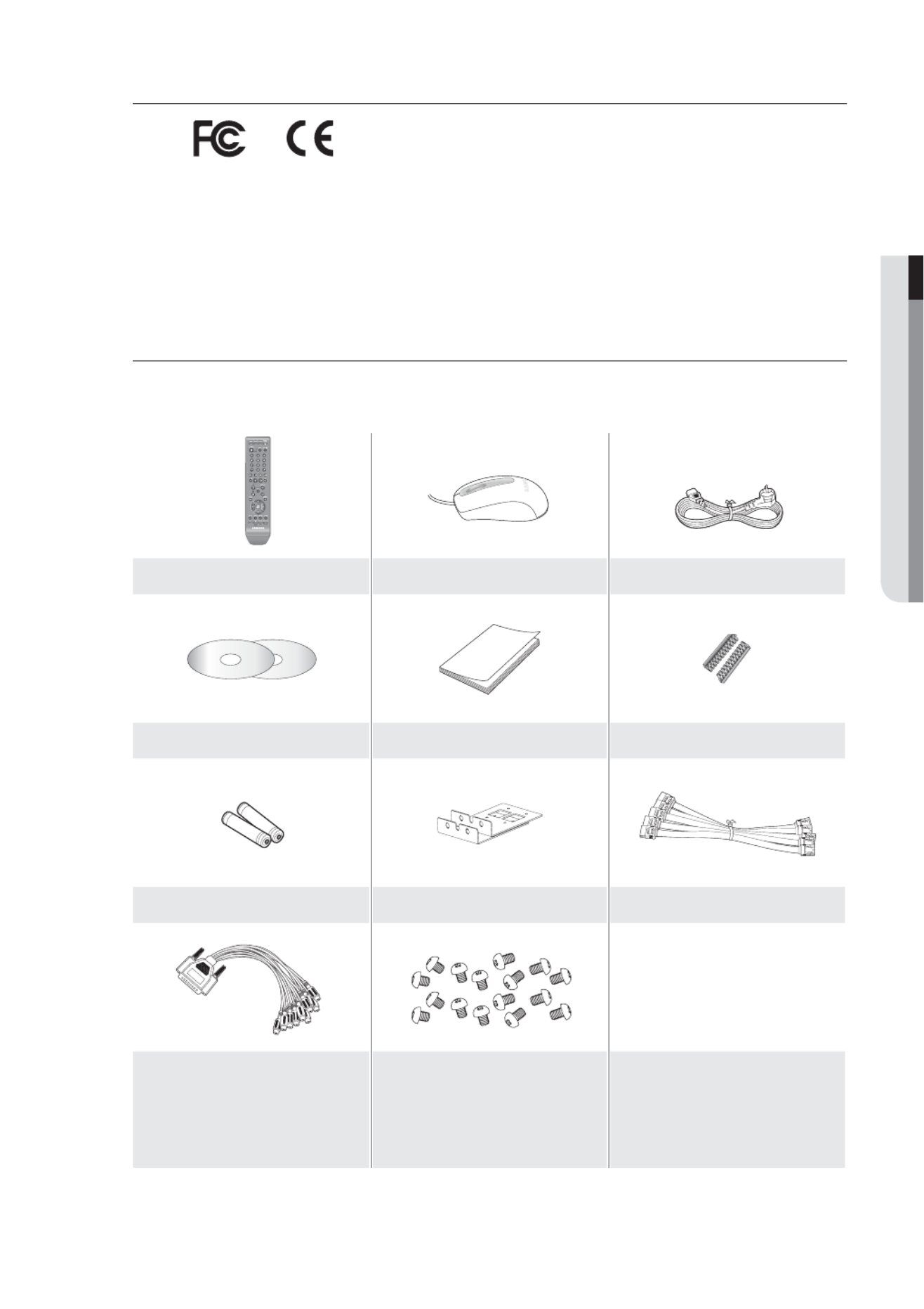
Package Contents
Please unwrap the product, and place the product on a fl at place or in the place to be installed.
Please check the following contents are included in addition to the main unit.
Remote Control Mouse Power Cable
NET-i Pro Software / User Manual CD User Manual RS-485 Connector Port
Remote Control Battery (AAA) Bracket Rack SATA Cable
Audio Extension Cable (optional)
(SHR-7xxx/8xxx)
HDD Fixing Screw
(SHR-6082, 6162, 6164, 7082, 7162,
8082, 8162 : 16EA)
(SHR-6080, 6160, 6163, 7080, 7160,
8080, 8160 : 20EA)
M

6_ overview
overview
CONTENTS
OVERVIEW
2
2 Features
3 Important Safety Instructions
4 Before Start
8 Part Names and Functions (Front)
10 Part Names and Functions (Rear)
13 Remote Control
INSTALLATION
15
15 Checking the installation environment
16 Rack Installation
16 HDD Addition
CONNECTING WITH OTHER DEVICE
24
24 Connecting the Video, Audio, and Monitor
24 Connecting the USB
25 Connecting External SATA HDD
25 Connecting POS Device
25 Connecting the Alarm Input/Output
26 Connecting the RS-485 Device
27 Connecting the Network
LIVE
29
29 Getting Started
31 Live Screen Configuration
35 Live Mode
37 Spot Out
38 Zoom
38 Audio On/Off
38 Freeze
39 Event Monitoring
USING THE DVR
40
40 System Setup
50 Setting the Device
58 Setting the Recording
61 Setting the Event
64 Backup
65 Network Configuration
72 Controlling a PTZ device

English _7
OVERVIEW
SEARCH & PLAY
74
74 Search
77 Playback
WEB VIEWER
78
78 Introducing Web Viewer
79 Connecting Web Viewer
81 Using Live Viewer
87 Using Search Viewer
91 Viewer Setup
101 About
BACKUP VIEWER
102
102 SEC Backup Viewer
APPENDIX
104
104 Product Specification (SHR-6xxx)
107 Product Specification (SHR-7xxx, 8xxx)
110 Product Overview
111 Default Setting
114 Troubleshooting

English _9
OVERVIEW
Part Names Functions
LED Indicator
ALARM : Lights on when an event occurs.
HDD : Displays the normal access to HDD.
Upon access to HDD, LED repeats on and off.
NETWORK : Displays both network connection and data transfer status.
BACKUP : Displays when Backup is in progress.
REC : Lights on when recording is in progress.
Camera Control
PTZ : Sets PTZ Mode ON/OFF.
ZOOM(TELE) : Sets the screen to the p9-x2 digital zoom.
Runs the TELE function in the PTZ Mode.
FREEZE(WIDE) : Runs the FREEZE function in the Live Mode.
Runs the WIDE function in the PTZ Mode.
BACKUP(VIEW) : Runs the BACKUP function.
Runs the Preset View function in the PTZ Mode.
SEARCH(PRESET) : Goes to the search screen.
Runs the Preset Setup function in the PTZ Mode.
REC Starts or ends the recording.
/
Step Rewind (
) : Used for backward frame-by-frame search while in PAUSE.
Fast Rewind () : Used for quick backward search while in Play.
(-x2, -x4, -x8, -x16, -x32, -x64)
Stop : Used to stop the playback.
► /Play/Pause : Used to pause or resume the screen.
/Fast Forward () : Used for quick forward playback. (x2, x4, x8, x16, x32, x64)
Step Forward (
) : Used for forward frame-by-frame search while in PAUSE.
Direction /
Select Button
Used to change a value or move the cursor up/down/left/right ( ).◄ ►
Selects a menu item or executes the selected menu.
USB Port 1 / 2 Connects the USB devices.
MODE
Each button press in the Live Mode switches the screen to 16-, 9-, 4-, 6-, 8-, 13- split screen,
PIP, and auto sequence mode in order.
In play mode, each press of the button will switch the screen mode to 13-, 1-, 4-, 9-, and
16-split in order. (1 live channel + (N-1) live channel)
AUDIO Sets Audio ON/OFF.
ALARM Cancels the ALARM LED and the audible alarm when the alarm is going off, and to remove the
icon.
MENU/RETURN Either goes to the system menu screen or moves to the upper menu from the lower menu.
Channel Used to select channel numbers directly in the Live Mode, or numbers in the numeric input
mode.
Jog shuttle
When a scroll bar appears in each menu, acts as a scrolling.
In Play mode, - Jog : Pauses the playback and steps backward or forward.
- Shuttle : Fast playback forward or backward.
OPEN/CLOSE
Used to open and close the DVR-RW disc tray. (available for SHR-6082/6162/6164/7082/7162
/8082/8162 only)
Power Power LED : Displays the power ON/OFF status.
Power Button : Used to turn the DVR ON/OFF.

10_ overview
overview
PART NAMES AND FUNCTIONS (REAR)
6080/6082
6160/6162/6163/6164
7080/7082
7160/7162
1 2 3 4 5 6 7 8 9 10 12 141311
1 32 4 5 6 7 8 9 10 12 141311
3
21 5 6 8 9 10 11 12 1413
1 2 3 5 6 8 9 10 11 12 1413

English _11
OVERVIEW
8080/8082
8160/8162
1 2 3 4 5 6 7 8 9 10 12 141311
13
24 5 6 7 8 9 10 12 141311

12_ overview
overview
Part Names Functions
VIDEO OUT Composite Video Signal Output Port (BNC type connector).
AUDIO OUT Audio Signal Output Port (RCA jack).
VGA VGA Video Signal Output Port.
HDMI HDMI connector port.
AUDIO IN
Audio input signal port (RCA jack) and port for optional audio extension cable.
SHR-716x/816x (Audio 5~16CH)
SHR-808x/708x (Audio 5~8CH)
USB USB connector port.
SATA 1/2 Ports used for external storage device connections. (SATA HDD)
NETWORK NETWORK connector port.
SPOT
A live screen output port, separate from the VIDEO OUT.
SPOT 1 : Supports Single, 4-, 9-, 16-split, and Auto Sequence modes
SPOT 2 : Supports Single, 4-split, and Auto Sequence modes (only for 5 ~ 8 CH).
SPOT 3 : Supports Single, 4-split, and Auto Sequence modes (only for 9 ~ 12 CH).
SPOT 4 : Supports Single, 4-split, and Auto Sequence modes (only for 13 ~ 16 CH).
SHR-8162/8160 : SPOT 1, 2, 3, 4
SHR-8082/8080 : SPOT 1, 2
SHR-6xxx/7xxx : SPOT 1
RS-485 Used for RS-485 communication. (TX+, TX-, RX+, RX-)
ALARM
- ALARM IN 1~16(SHR-616x/716x/816x) : Alarm Input port.
- ALARM IN 1~8(SHR-608x/708x/808x) : Alarm Input port.
- ALARM RESET IN : Alarm Reset port.
- ALARM OUT 1~4 : Alarm Output port.
LOOP OUT Used to transfer a video signal to other video devices.
VIDEO IN Composite Video Signal Input Port (BNC type connector).
AC 100-240V~ IN AC 100 ~ 230V (PAL)
AC 110 ~ 220V (NTSC)

English _13
OVERVIEW
REMOTE CONTROL
DVR
Available after switching to DVR mode by pressing the [ ] button on the remote control.DVR
Using the numeric buttons
CHANNEL 1–9 Press each button between 1 to 9.
CHANNEL 10 Press the [+10] button fi rst, then press the 0 button again within 3 seconds.
CHANNEL 11–16 Press the [
+10] button fi rst, then press any number between 1 to 6 within 3 seconds.
SEARCH
Displays the search menu.
POWER
Displays the Exit pop up screen.
NUMBER [0~+10]
Used as the numeric input keys, or displays a single
channel.
T/W
Zooms in or out.
BACKUP
Displays the Backup Menu.
MODE
Changes the screen mode.
MENU
Goes to the system menu screen.
Up/Down/Left/Right( )/ENTER▲▼◄ ►
Moves the cursor up/down/left/right, and runs the
Select Menu.
FREEZE
Freezes the screen temporarily.
ZOOM
Runs the digital zoom (x2) function.
VIEW
Runs the View function in the PTZ mode.
OPEN/CLOSE
Opens or closes the CD tray.
DVR
Activates the DVR function.
ID
Sets the ID of the system.
Select 2 digits from 0 ~ 9 while pressing the ID Key.
PTZ
Displays or ends PTZ.
SCROLL ,.
Moves the menu scroll.
RETURN
Returns to the previous screen.
AUDIO
Turns Audio on/off.
ALARM
Cancels the Alarm.
REC LOCK
Selects the recording lock function.
PRESET
Displays the Preset Setup.
REC
Starts or ends the live recording.
Skip Backward (by unit time),
Slow Rewind, Slow Forward,
Skip Forward (by unit time) Move Frame
While paused, moves to the previous/next frame.
FR, STOP, PLAY/PAUSE, FF

14_ overview
overview
MONITOR
Available after switching to Monitor mode by pressing the [ ] button on the remote control.MONITOR
Using the Numeric buttons
CHANNEL 1–9 Press any button among 1 to 9.
Changing the Remote Control ID
Press the ID button of the remote control and check the ID displayed on the DVR screen.
The factory default ID of the remote control is 00.
Enter 2 digits of your selection in order, while pressing the system [ ] button.ID
When ID input is done, press the system [ ] button again to check the setting.ID
If you want to change the remote control ID to 08: Press 0 and 8 in order while the system [ ] button is pressed.ID
Remote control's ID and DVR’s ID should be matched for proper operation. Refer to “Remote Devices”. (Page 54)
1.
2.
3.
M
AUTO
Selects the screen status automatically.
POWER
Turns the monitor power on/off.
NUMBER [0~9]
Changes the system ID.
+/–
Adjusts the audio volume.
ID RESET
Initializes the ID value to 00.
P.MODE
Selects the screen mode.
MENU
Displays the Setup Menu.
Up/Down/Left/Right( )/ENTER▲▼◄ ►
Moves the cursor up/down/left/right, and runs the
Select Menu.
FREEZE
Screen Freeze.
UNDER SCAN
Displays the video screen within a screen.
MONITOR
Activates the monitor function.
ID
Sets the ID.
Select 2 digits from 0 ~ 9 while pressing the ID Key.
MUTE
Mutes the audio out.
SOURCE
Selects the input signal source.
PIP
Selects or deselects the PIP function.

English _15
INSTALLATION
Please be noticed with the followings before you use the product.
Do not use the product outdoor.
Do not spill water or liquid in the connection part of the product.
Do not impose the system to excessive shock or force.
Do not pull out the power plug forcefully.
Do not disassemble the product on your own.
Do not exceed the rated input/output range.
Use a certifi ed power cord only.
For the product with an input ground, use a grounded power plug.
CHECKING THE INSTALLATION ENVIRONMENT
Samsung Digital Video Recorder (“DVR” hereinafter) is a
state-of-art security device, and contains mass storage hard
disk(s) and critical circuits inside.
When the temperature rises inside the product, the product
may breakdown and the product life be shortened. Please
pay attention to the following recommendations before
installation.
The followings are the recommendations when Samsung DVR is installed on a rack.
Please ensure that the rack inside is not sealed.
Please ensure the air is circulated through the inlet/outlet as shown in the picture.
If the DVR or other devices on a rack is to be stacked as in the picture, provide a
suitable space or install a ventilating opening for air circulation.
For natural air convection, place the inlet at the bottom of the rack and the outlet on
top.
It is strongly recommended that a fan motor is installed at the inlet and the outlet for air
circulation. (Please fi t a fi lter at the inlet to screen dust or foreign substances.)
Please maintain the temperature inside the rack or surrounding areas between 0°C ~
40°C (32°F ~ 104°F) as shown in the fi gure 1.
Rack Mount Instructions - The following or similar rack-mount instructions are
included with the installation instructions :
A) Elevated Operating Ambient - If installed in a closed or multi-unit rack assembly, the
operating ambient temperature of the rack environment may be greater than room
ambient. Therefore, consideration should be given to installing the equipment in an
environment compatible with the maximum ambient temperature (Tma) specifi ed by
the manufacturer.
B) Reduced Air Flow - Installation of the equipment in a rack should be such that the
amount of air fl ow required for safe operation of the equipment is not compromised.
C) Mechanical Loading - Mounting of the equipment in the rack should be such that a hazardous condition is
not achieved due to uneven mechanical loading.
D) Circuit Overloading - Consideration should be given to the connection of the equipment to the supply circuit
and the effect that overloading of the circuits might have on overcurrent protection and supply wiring.
Appropriate consideration of equipment nameplate ratings should be used when addressing this concern.
E) Reliable Earthing - Reliable earthing of rack-mounted equipment should be maintained. Particular attention should
be given to supply connections other than direct connections to the branch circuit (e.g. use of power strips).
•
•
•
•
•
•
•
•
1.
2.
3.
4.
5.
6.
One Year: 24HR X 365 DAY =8,760 HR
Temperature
Unit: ºC
Life (Unit: HOURS)
[Figure 1]
[Figure 2]
installation

16_ installation
installation
RACK INSTALLATION
Loosen the screws on both sides (4 screws on each side) and install
the Bracket-Rack as shown in the fi gure, and then fasten the screws
on both sides (4 screws on each side).
Fix the screws not to be loosened by vibrations.
HDD ADDITION
You can install additional HDDs.
Make sure to unplug the power cord from the wall outlet to prevent possible electric shock, injury or product
damage.
Please consult your provider for further information on HDD installation since improper installation or settings may
damage the product.
Number of HDDs supported : SHR-6082/6162/6164/7082/7162/8082/8162 : Default 1 HDD + Up to 4 HDDs added
SHR-6080/6160/6163/7080/7160/8080/8160 : Default 1 HDD + Up to 5 HDDs added
Cautions for data loss (HDD care)
Please pay attention so that the data inside the HDD is not damaged.
Before adding a HDD, please check the compatibility with this DVR product.
HDD is vulnerable to malfunction due to its sensitive nature against externalities or shocks during operation.
Please ensure that the HDD is free from such shock or externalities.
We are not liable for any damage to the HDD incurred by user’s carelessness or externalities.
Cases might cause damage to HDD or recorded data
To minimize the risk of data loss from a damaged HDD, please backup data as often as possible.
Data may be lost due to external impacts during disassembly or installation of the DVR.
HDD may be damaged if the DVR is suddenly stopped by a power cut or power off during operation.
HDD or fi les stored inside may be damaged if the main body is moved or impacted during the HDD operation.
Cautions when adding a HDD
When adding a HDD, pay attention so that the cable does not get caught between unsuitable spaces or
the cable’s insulation does not come off.
Pay attention so as not to lose the disassembly screws or accessories.
If the screws or accessories are not put together, the product may breakdown or not operate properly.
Please check the HDD compatibility before adding a HDD.
Please contact your nearest dealer to obtain the list of compatible devices.
J
1.
2.
3.

English _17
INSTALLATION
Adding a HDD
Make sure to unplug the power cord from the wall outlet before proceeding with the installation.
Number of HDDs to install : SHR-6082/6162/6164/7082/7162/8082/8162 : Default 1 HDD + Up to 4 HDDs added
SHR-6080/6160/6163/7080/7160/8080/8160 : Default 1 HDD + Up to 5 HDDs added
By factory default, the master unit is equipped with one HDD.
The following instructions are when you have installed the maximum number of HDDs on the master unit.
First, loosen the screws in the left and right sides
and remove the cover.
1) If adding HDDs to SHR-6080/6160 / 6163
Loosen the screws (x4) in the left/right and upper
sides and remove the upper and lower brackets.
Install HDDs (x3) on the lower bracket and fi x them
with screws.
The screw (UNC 6-32) to use in the installation comes
with the HDD.
Firmly secure the screw so that it can not get loose from
such as vibration.
Install HDDs (x2) on the upper bracket and fi x them
with screws.
M
1.
2.
3.
4.
Cover
Upper Bracket
Lower
Bracket
Lower Bracket
Upper Bracket
Add
Installed by
default
Add
Add
Add
Add

18_ installation
installation
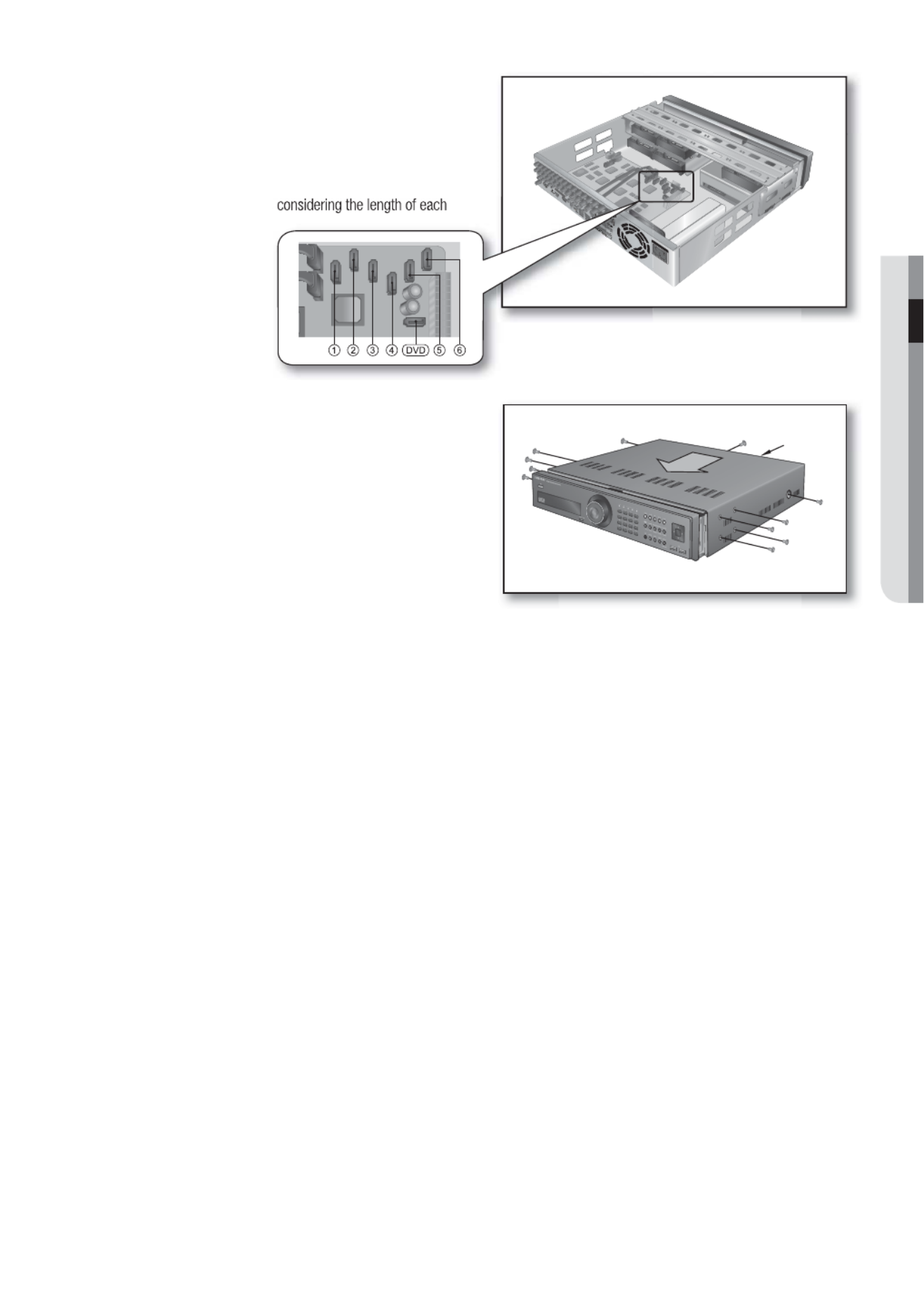
When the installation of additional HDDs is done,
insert the lower and upper brackets into the DVR
and fi x them with the provided screws.
When the installation of additional HDDs is done,
connect the power cable and connect the HDD
signal cables (SATA Cable) to connectors ~ on c h
the main board.
You can check the HDD map directly on the DVR.
Refer to “ > Storage Device HDD Map”. (Page 52)
Note that the order of the HDD data cable is nothing to
do with the operation. Just make arrangements of the
connectors considering the length of each connector.
SHR-6080/6160/6163 do not support DVD media.
5.
6.
Upper Bracket
Lower
Bracket

English _19
INSTALLATION
2) If adding HDDs to SHR-7080/7160/8080/8160
Loosen the screws (x4) in the left/right and upper
sides and remove the upper and lower brackets.
Install HDDs (x3) on the lower bracket and fi x them
with screws.
The screw (UNC 6-32) to use in the installation comes
with the HDD.
Firmly secure the screw so that it can not get loose from
such as vibration.
Install HDDs (x2) on the upper bracket and fi x them
with screws.
When the installation of additional HDDs is done,
insert the lower and upper brackets into the DVR
and fi x them with the provided screws.
2.
3.
4.
5.
Upper Bracket
Lower
Bracket
Lower Bracket
Upper Bracket
Add
Installed by
default
Add
Add
Add
Add
Upper Bracket
Lower
Bracket

20_ installation
installation
When the installation of additional HDDs is done,
connect the power cable and connect the HDD
signal cables (SATA Cable) to connectors ~ on c h
the main board.
You can check the HDD map directly on the DVR.
Refer to “ > Storage Device HDD Map”. (Page 52)
Note that the order of the HDD data cable is nothing to
do with the operation. Just make arrangements of the
connectors considering the length of each connector.
3) If adding HDDs to SHR-6082/6162/6164
Loosen the screws (x4) in the left/right and upper
sides to remove the upper bracket and loosen the
lower screws (x2) to remove the lower bracket.
Install a HDD (x1) on the lower bracket and fi x it with
screws.
Install HDDs (x3) on the upper bracket and fi x them
with screws.
6.
2.
3.
4.
Upper Bracket
Lower Bracket
Lower Bracket
Upper Bracket
Add
Installed by default
Add
Add
Add

English _21
INSTALLATION
When the installation of additional HDDs is done,
insert the lower and upper brackets into the DVR
and fi x them with the provided screws.
When the installation of additional HDDs is done,
connect the power cable and connect the HDD
data cables (SATA Cable) to connectors ~ on c h
the main board.
Note that the number of a HDD data calbe is nothing to
do with operation of the HDD. Just make arrangements
of the connectors considering the length of each
connector.
5.
6.
Upper Bracket
Lower
Bracket

22_ installation
installation
4) If adding HDDs to SHR-7082/7162/8082/8162
Loosen the screws (x4) in the left/right and upper
sides to remove the upper bracket and loosen the
lower screws (x2) to remove the lower bracket.
Install a HDD (x1) on the lower bracket and fi x it with
screws.
Install HDDs (x3) on the upper bracket and fi x them
with screws.
When the installation of additional HDDs is done,
insert the lower and upper brackets into the DVR
and fi x them with the provided screws.
2.
3.
4.
5.
Upper Bracket
Lower Bracket
Upper Bracket
Lower
Bracket
Lower Bracket
Upper Bracket
Add
Installed by default
Add
Add
Add
English _23
INSTALLATION
When the installation of additional HDDs is done,
connect the power cable and connect the HDD
data cables (SATA Cable) to connectors ~ on c h
the main board.
Note that the number of a HDD data calbe is nothing to
do with operation of the HDD. Just make arrangements
of the connectors considering the length of each
connector.
Check if the connectors are properly connected and
there is no problem with wiring, and close the cover
and fi x it with screws.
6.
7.
Cover

24_ connecting with other device
The following gures are based on Model SHR-8162.
CONNECTING THE VIDEO, AUDIO, AND MONITOR
CONNECTING THE USB
There are two USB ports at the front and one at the back of the product.
You can connect a USB HDD, USB CD/DVD player, USB memory or mouse to the USB port.
If a USB HDD is connected to the system, recognition and settings are available in “Menu Setting the Device > >
Storage Device”. (Page 52)
This product supports hot-plugging, which connects/removes the USB device during the system operation.
The USB type HDD must be set as Master.
If you use the USB device for Backup purposes, format it with FAT32 on PC if it is not formatted on the DVR.
M
1.
2.
3.
4.
J
VIDEO IN
AUDIO IN
SPOT AC 100-240V~IN
VIDEO OUT
(VGA)
VIDEO OUT
(composite)
AUDIO OUT
HDMI
VIDEO IN
connecting with other device

English _25
CONNECTING WITH OTHER DEVICE
CONNECTING EXTERNAL SATA HDD
SHR-6xxx does not support a port for SATA connection.
There are two external SATA ports on the rear side of the product.
If an external SATA HDD is connected to the system, recognition and settings are available in “ > Menu Device >
Storage Device”.
The DVR supports Hot Plug function to allow connection and disconnection of SATA HDD devices while the
system is in use.
Only one SATA HDD can be connected to an external SATA port.
Use a cable shorter than 1 m for the external SATA HDD connections.
CONNECTING POS DEVICE
You can connect a POS device to the RS-232C port on the product’s rear side when you connect it directly with
a RS-232C cable.
Connection setup for the RS-232C port is available in “ > > ”, press the Menu Device POS Devices
<POS Device Setup Baudrate, Parity, Data, Stop bit and Transfer Type> button and set < >. (Page 55)
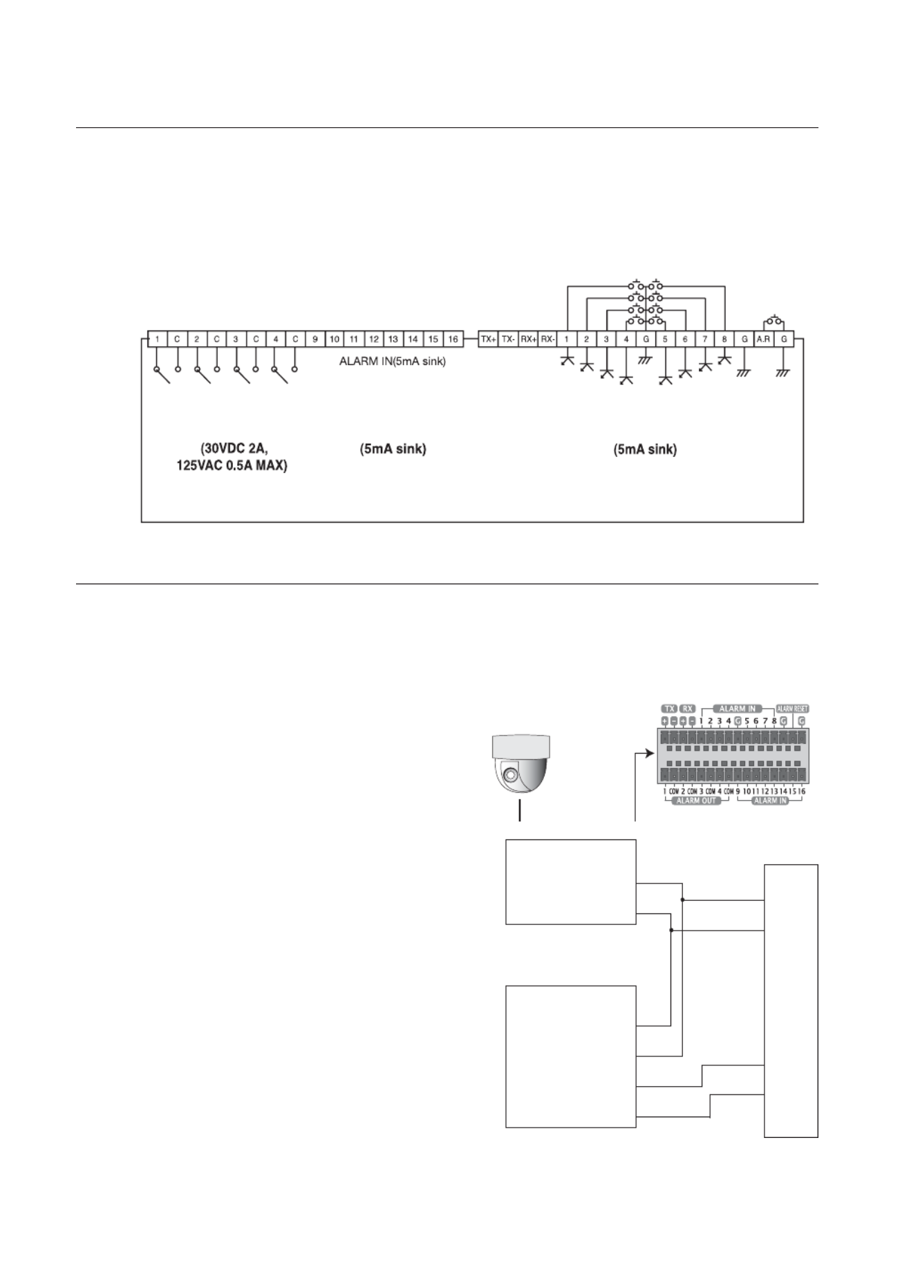
CONNECTING THE ALARM INPUT/OUTPUT
The Alarm In/Out port at the back is composed of the following.
Alarm In/Out Port on SHR-608x/708x/808x
Alarm In/Out Port on SHR-616x/716x/816x
M
1.
2.
3.
J
1.
2.
1.
2.
26_ connecting with other device
connecting with other device
ALARM IN 1 ~ 8 (SHR-608x/708x/808x) : Alarm Input Port
ALARM IN 1 ~ 16 (SHR-616x/716x/816x) : Alarm Input Port
ALARM RESET : On receiving an Alarm Reset signal, the system cancels the current Alarm Input and resumes
sensing.
ALARM OUT 1 ~ 4 : Alarm Output Port
CONNECTING THE RS-485 DEVICE
Connect the RS-485 device through the back port.
For example, you can connect and control the PTZ camera which supports the RS-485 communication.
Transfer Type : You may select either Half Duplex or
Full Duplex as the data transfer type.
Baud Rate : Supported Baud rates are 600/1200/
2400/4800/9600/19200/38400.
Check if the RS-485 device is compatible with the
product rst.
Pay attention not to change the polarity (+/–) of the
RS-485 device when connecting it.
Depending on camera’s type, connection polarity can be
different.
For further information, refer to the respective PTZ
Camera’s documentation.
Ex : DVR(TX+/–)
SCC-C6433,35(RX+/–)
DVR(TX+/–)
SCC-C6403,07(TX+/–)
•
•
•
•
M
•
•
M
ALARM OUT ALARM IN ALARM IN
PTZ device
Half Duplex Type
Data (–)
Data (+)
Full Duplex Type
Rx(+)
Rx(–)
Tx(–)
Tx(+)
Rear
Tx(–)
Tx(+)
Rx(–)
Rx(+)

English _27
CONNECTING WITH OTHER DEVICE
CONNECTING THE NETWORK
Connecting to Internet through Ethernet (10/100/1000BaseT)
Connecting to the Internet using the router
Router
xDSL or Cable
Modem
xDSL or Cable
Modem
External Remote
PC
DDNS Server
(Data Center)
INTERNET
Windows
NET-i Pro
Back Bone
Hub/Switcher
Hub/Switcher
RJ-45 Ethernet Cable
(Direct Cable)
INTERNET

28_ connecting with other device
connecting with other device
Connecting to Internet through ADSL
Hub/Switcher
Phone(ADSL) Line ADSL MODEM
RJ-45 Ethernet Cable
(Direct Cable)
Windows
NET-i Pro
INTERNET

English _29
LIVE
GETTING STARTED
Starting the system
Connect the power cable of the DVR to the wall outlet.
Press the Power button on the front panel.
You will see the initialization screen.
The initialization process will last about 1 minute in the
order of icons appeared.
If a new HDD is installed, the initialization process may take
a longer time.
The live screen appears with a beep.
Shutting Down the System
You can shut down the system only if you have logged in to the DVR.
You should have the < > permission to shut down the system if you are not an admin.Shutdown
Press the [ ] button on the remote control or the POWER
front panel, or right-click to display the context sensitive
menu and select < >.Shutdown
The “ ” con rmation window appears.Shutdown
Use the arrow keys on the remote control or the front panel
to move to < > and press the [ ] button or click OK ENTER
<OK>.
The system will shut down.
For the permission management, refer to “Permission
Management Setting Permissions > ”. (Page 45)
1.
2.
3.
4.
1.
2.
3.
M
live
Shutdown
Are you sure to shutdown?
OK Cancel
Produkt Specifikationer
| Mærke: | Hanwha |
| Kategori: | Overvågningskamera |
| Model: | SHR-6160 |
Har du brug for hjælp?
Hvis du har brug for hjælp til Hanwha SHR-6160 stil et spørgsmål nedenfor, og andre brugere vil svare dig
Overvågningskamera Hanwha Manualer

24 September 2024
24 September 2024
24 September 2024
1 September 2024
31 August 2024
30 August 2024
30 August 2024
30 August 2024
30 August 2024
30 August 2024
Overvågningskamera Manualer
- Overvågningskamera Bosch
- Overvågningskamera Denver
- Overvågningskamera Sony
- Overvågningskamera Canon
- Overvågningskamera Netis
- Overvågningskamera Samsung
- Overvågningskamera Panasonic
- Overvågningskamera Extech
- Overvågningskamera Moog
- Overvågningskamera TP-Link
- Overvågningskamera Philips
- Overvågningskamera Vitek
- Overvågningskamera Gigaset
- Overvågningskamera Pioneer
- Overvågningskamera Mitsubishi
- Overvågningskamera Braun
- Overvågningskamera Logitech
- Overvågningskamera Emos
- Overvågningskamera Google
- Overvågningskamera Technaxx
- Overvågningskamera HP
- Overvågningskamera Waeco
- Overvågningskamera Garmin
- Overvågningskamera Sanyo
- Overvågningskamera Grundig
- Overvågningskamera D-Link
- Overvågningskamera Arlo
- Overvågningskamera Motorola
- Overvågningskamera Asus
- Overvågningskamera Toshiba
- Overvågningskamera Pyle
- Overvågningskamera Kodak
- Overvågningskamera Furrion
- Overvågningskamera InFocus
- Overvågningskamera Nedis
- Overvågningskamera Friedland
- Overvågningskamera Abus
- Overvågningskamera Planet
- Overvågningskamera Adj
- Overvågningskamera Hama
- Overvågningskamera Creative
- Overvågningskamera Thomson
- Overvågningskamera Belkin
- Overvågningskamera Edimax
- Overvågningskamera Burg Wächter
- Overvågningskamera Clas Ohlson
- Overvågningskamera DataVideo
- Overvågningskamera Strong
- Overvågningskamera TRENDnet
- Overvågningskamera Smartwares
- Overvågningskamera Trevi
- Overvågningskamera Trust
- Overvågningskamera Laserliner
- Overvågningskamera Blaupunkt
- Overvågningskamera JVC
- Overvågningskamera Honeywell
- Overvågningskamera Uniden
- Overvågningskamera Buffalo
- Overvågningskamera Linksys
- Overvågningskamera Megasat
- Overvågningskamera Cisco
- Overvågningskamera EZVIZ
- Overvågningskamera König
- Overvågningskamera Elro
- Overvågningskamera Gembird
- Overvågningskamera Powerfix
- Overvågningskamera Alpine
- Overvågningskamera Netgear
- Overvågningskamera Maginon
- Overvågningskamera Yale
- Overvågningskamera Withings
- Overvågningskamera Nest
- Overvågningskamera Kerbl
- Overvågningskamera Vtech
- Overvågningskamera Exibel
- Overvågningskamera Genie
- Overvågningskamera Vaddio
- Overvågningskamera Bresser
- Overvågningskamera Western Digital
- Overvågningskamera Anker
- Overvågningskamera Digitus
- Overvågningskamera Zebra
- Overvågningskamera Jensen
- Overvågningskamera Alecto
- Overvågningskamera Flamingo
- Overvågningskamera Rollei
- Overvågningskamera Olympia
- Overvågningskamera Xiaomi
- Overvågningskamera Niceboy
- Overvågningskamera Aiptek
- Overvågningskamera Schneider
- Overvågningskamera B/R/K
- Overvågningskamera Marmitek
- Overvågningskamera Tesla
- Overvågningskamera Imou
- Overvågningskamera Ricoh
- Overvågningskamera Nexxt
- Overvågningskamera Aida
- Overvågningskamera APC
- Overvågningskamera Foscam
- Overvågningskamera Lorex
- Overvågningskamera Ikan
- Overvågningskamera Velleman
- Overvågningskamera LevelOne
- Overvågningskamera Marshall
- Overvågningskamera FLIR
- Overvågningskamera Perel
- Overvågningskamera Swann
- Overvågningskamera Vivotek
- Overvågningskamera Joblotron
- Overvågningskamera JUNG
- Overvågningskamera ORNO
- Overvågningskamera Binatone
- Overvågningskamera ZyXEL
- Overvågningskamera Fortinet
- Overvågningskamera Netatmo
- Overvågningskamera Tenda
- Overvågningskamera Eufy
- Overvågningskamera Ring
- Overvågningskamera M-e
- Overvågningskamera Overmax
- Overvågningskamera Somfy
- Overvågningskamera Y-cam
- Overvågningskamera Hikvision
- Overvågningskamera Monacor
- Overvågningskamera ION
- Overvågningskamera Raymarine
- Overvågningskamera Ubiquiti Networks
- Overvågningskamera AVerMedia
- Overvågningskamera EnGenius
- Overvågningskamera Reolink
- Overvågningskamera Grandstream
- Overvågningskamera Trebs
- Overvågningskamera EVE
- Overvågningskamera Renkforce
- Overvågningskamera Marshall Electronics
- Overvågningskamera Manhattan
- Overvågningskamera SPC
- Overvågningskamera Caliber
- Overvågningskamera Pentatech
- Overvågningskamera Switel
- Overvågningskamera AVtech
- Overvågningskamera LogiLink
- Overvågningskamera Orion
- Overvågningskamera Eminent
- Overvågningskamera Kramer
- Overvågningskamera QSC
- Overvågningskamera Brilliant
- Overvågningskamera Lanberg
- Overvågningskamera Hive
- Overvågningskamera Siedle
- Overvågningskamera BirdDog
- Overvågningskamera Evolveo
- Overvågningskamera Genius
- Overvågningskamera KJB Security Products
- Overvågningskamera Valueline
- Overvågningskamera Provision-ISR
- Overvågningskamera Quantum
- Overvågningskamera Axis
- Overvågningskamera ACTi
- Overvågningskamera CRUX
- Overvågningskamera Avanti
- Overvågningskamera Vimar
- Overvågningskamera Aluratek
- Overvågningskamera Dahua Technology
- Overvågningskamera Chacon
- Overvågningskamera SereneLife
- Overvågningskamera ZKTeco
- Overvågningskamera AG Neovo
- Overvågningskamera Stabo
- Overvågningskamera EtiamPro
- Overvågningskamera First Alert
- Overvågningskamera Speco Technologies
- Overvågningskamera Boss
- Overvågningskamera Broan
- Overvågningskamera Conceptronic
- Overvågningskamera Avidsen
- Overvågningskamera Crestron
- Overvågningskamera Lindy
- Overvågningskamera Kogan
- Overvågningskamera AVMATRIX
- Overvågningskamera Delta Dore
- Overvågningskamera Promise Technology
- Overvågningskamera Sitecom
- Overvågningskamera DiO
- Overvågningskamera Minox
- Overvågningskamera Intellinet
- Overvågningskamera V-TAC
- Overvågningskamera Qian
- Overvågningskamera August
- Overvågningskamera IDIS
- Overvågningskamera Geovision
- Overvågningskamera Schwaiger
- Overvågningskamera Steren
- Overvågningskamera Elmo
- Overvågningskamera AViPAS
- Overvågningskamera UniView
- Overvågningskamera Equip
- Overvågningskamera Alfatron
- Overvågningskamera REVO
- Overvågningskamera Aqara
- Overvågningskamera Ernitec
- Overvågningskamera Setti+
- Overvågningskamera BZBGear
- Overvågningskamera PTZ Optics
- Overvågningskamera AVer
- Overvågningskamera Ferguson
- Overvågningskamera Moxa
- Overvågningskamera Inovonics
- Overvågningskamera Bea-fon
- Overvågningskamera Profile
- Overvågningskamera WyreStorm
- Overvågningskamera Allnet
- Overvågningskamera Aldi
- Overvågningskamera Airlive
- Overvågningskamera Aritech
- Overvågningskamera ACME
- Overvågningskamera KlikaanKlikuit
- Overvågningskamera Marquant
- Overvågningskamera Ednet
- Overvågningskamera Lumens
- Overvågningskamera Hombli
- Overvågningskamera Naxa
- Overvågningskamera Miniland
- Overvågningskamera Xavax
- Overvågningskamera Gira
- Overvågningskamera Interlogix
- Overvågningskamera DSC
- Overvågningskamera Boyo
- Overvågningskamera Iget
- Overvågningskamera EverFocus
- Overvågningskamera Adesso
- Overvågningskamera Satel
- Overvågningskamera Notifier
- Overvågningskamera Monoprice
- Overvågningskamera Beafon
- Overvågningskamera Chuango
- Overvågningskamera MicroView
- Overvågningskamera ETiger
- Overvågningskamera Videcon
- Overvågningskamera INSTAR
- Overvågningskamera Advantech
- Overvågningskamera Digital Watchdog
- Overvågningskamera Moen
- Overvågningskamera Ganz
- Overvågningskamera MEE Audio
- Overvågningskamera Mobotix
- Overvågningskamera Kwikset
- Overvågningskamera Ikegami
- Overvågningskamera Leviton
- Overvågningskamera Pelco
- Overvågningskamera Approx
- Overvågningskamera ClearOne
- Overvågningskamera Ebode
- Overvågningskamera Oplink
- Overvågningskamera Dorr
- Overvågningskamera Sonic Alert
- Overvågningskamera Linear PRO Access
- Overvågningskamera Summer Infant
- Overvågningskamera SMC
- Overvågningskamera Topica
- Overvågningskamera Iiquu
- Overvågningskamera Verint
- Overvågningskamera Brinno
- Overvågningskamera Rostra
- Overvågningskamera Caddx
- Overvågningskamera Spyclops
- Overvågningskamera EKO
- Overvågningskamera Kguard
- Overvågningskamera Woonveilig
- Overvågningskamera Accsoon
- Overvågningskamera Mobi
- Overvågningskamera Surveon
- Overvågningskamera Hollyland
- Overvågningskamera Epcom
- Overvågningskamera Indexa
- Overvågningskamera Lutec
- Overvågningskamera Whistler
- Overvågningskamera ClearView
- Overvågningskamera VideoComm
- Overvågningskamera IMILAB
- Overvågningskamera 3xLOGIC
- Overvågningskamera Inkovideo
- Overvågningskamera Weldex
- Overvågningskamera SecurityMan
- Overvågningskamera Mach Power
- Overvågningskamera Canyon
- Overvågningskamera CNB Technology
- Overvågningskamera Tapo
- Overvågningskamera Aigis
- Overvågningskamera Exacq
- Overvågningskamera Brickcom
- Overvågningskamera Laxihub
- Overvågningskamera Securetech
- Overvågningskamera EFB Elektronik
- Overvågningskamera NetMedia
- Overvågningskamera Videotec
- Overvågningskamera Illustra
- Overvågningskamera Atlona
- Overvågningskamera Nivian
- Overvågningskamera Arenti
- Overvågningskamera E-bench
- Overvågningskamera Blow
- Overvågningskamera Syscom
- Overvågningskamera Tecno
- Overvågningskamera Night Owl
- Overvågningskamera Guardzilla
- Overvågningskamera Astak
- Overvågningskamera Blink
- Overvågningskamera Milestone Systems
- Overvågningskamera Zavio
- Overvågningskamera Campark
- Overvågningskamera IPX
- Overvågningskamera Dedicated Micros
- Overvågningskamera Hamlet
- Overvågningskamera Annke
- Overvågningskamera Qoltec
- Overvågningskamera Digimerge
- Overvågningskamera Feelworld
- Overvågningskamera Wisenet
- Overvågningskamera Infortrend
- Overvågningskamera Epiphan
- Overvågningskamera HiLook
- Overvågningskamera Compro
- Overvågningskamera Vimtag
- Overvågningskamera Sonoff
- Overvågningskamera Gewiss
- Overvågningskamera Alula
- Overvågningskamera Insteon
- Overvågningskamera Costar
- Overvågningskamera ALC
- Overvågningskamera Security Labs
- Overvågningskamera Comtrend
- Overvågningskamera Seneca
- Overvågningskamera Avigilon
- Overvågningskamera American Dynamics
- Overvågningskamera Vosker
- Overvågningskamera Sentry360
- Overvågningskamera Owltron
- Overvågningskamera Petcube
- Overvågningskamera Enabot
- Overvågningskamera Luis Energy
- Overvågningskamera Sir Gawain
- Overvågningskamera VisorTech
- Overvågningskamera Atlantis Land
- Overvågningskamera B & S Technology
- Overvågningskamera I3International
- Overvågningskamera Ecobee
- Overvågningskamera Turing
- Overvågningskamera Wasserstein
- Overvågningskamera Qolsys
- Overvågningskamera Control4
- Overvågningskamera Milesight
- Overvågningskamera GVI Security
- Overvågningskamera Conbrov
- Overvågningskamera HuddleCamHD
- Overvågningskamera Defender
- Overvågningskamera IOIO
- Overvågningskamera BIRDFY
- Overvågningskamera I-PRO
- Overvågningskamera DVDO
- Overvågningskamera TCP
- Overvågningskamera Bolin Technology
- Overvågningskamera Nextech
- Overvågningskamera Tuya
- Overvågningskamera Bolide
- Overvågningskamera Telycam
- Overvågningskamera Arecont Vision
- Overvågningskamera Schlage
Nyeste Overvågningskamera Manualer
7 April 2025
7 April 2025
6 April 2025
29 Marts 2025
28 Marts 2025
20 Marts 2025
20 Marts 2025
20 Marts 2025
13 Marts 2025
8 Marts 2025