Hanwha XND-6081V Manual
Hanwha
Overvågningskamera
XND-6081V
Læs nedenfor 📖 manual på dansk for Hanwha XND-6081V (65 sider) i kategorien Overvågningskamera. Denne guide var nyttig for 14 personer og blev bedømt med 4.5 stjerner i gennemsnit af 2 brugere
Side 1/65

NETWORK CAMERA
User Manual
XNV-6081/XNV-6081R/XNV-8081R
XND-6081V/XND-6081RV/XND-8081RV
XND-6081F/XND-6081RF/XND-8081RF

Copyright
©2019 Hanwha Techwin Co., Ltd. All rights reserved.
Trademark
Each of trademarks herein is registered. The name of this product and other trademarks mentioned in this manual are the registered trademark of their
respective company.
Restriction
Copyright of this document is reserved. Under no circumstances, this document shall be reproduced, distributed or changed, partially or wholly, without
formal authorization.
Disclaimer
Hanwha Techwin makes the best to verify the integrity and correctness of the contents in this document, but no formal guarantee shall be
provided. Use of this document and the subsequent results shall be entirely on the user’s own responsibility. Hanwha Techwin reserves the
right to change the contents of this document without prior notice.
Design and specications are subject to change without prior notice.
The initial administrator ID is “admin” and the password should be set when logging in for the rst time.
Please change your password every three months to safely protect personal information and to prevent the damage of the information
theft.
Please, take note that it’s a user’s responsibility for the security and any other problems caused by mismanaging a password.
Network Camera
User Manual
English _3
●●overview
important Safety inStructionS
1. Read these instructions.
2. Keep these instructions.
3. Heed all warnings.
4. Follow all instructions.
5. Do not use this apparatus near water.
6. Clean the contaminated area on the product surface with a soft, dry cloth or a damp cloth.
(Do not use a detergent or cosmetic products that contain alcohol, solvents or surfactants or oil constituents
as they may deform or cause damage to the product.)
7. Do not block any ventilation openings, Install in accordance with the manufacturer’s instructions.
8. Do not install near any heat sources such as radiators, heat registers, stoves, or other apparatus (including
amplifiers) that produce heat.
9. Do not defeat the safety purpose of the polarized or grounding-type plug. A polarized plug has two blades
with one wider than the other. A grounding type plug has two blades and a third grounding prong. The wide
blade or the third prong are provided for your safety. If the provided plug does not fit into your outlet, consult
an electrician for replacement of the obsolete outlet.
10. Protect the power cord from being walked on or pinched particularly at plugs, convenience receptacles, and
the point where they exit from the apparatus.
11. Only use attachments/ accessories specified by the manufacturer.
12. Use only with the cart, stand, tripod, bracket, or table specified by the manufacturer,
or sold with the apparatus. When a cart is used, use caution when moving the cart/
apparatus combination to avoid injury from tip-over.
13. Unplug this apparatus during lighting storms or when unused for long periods of time.
14. Refer all servicing to qualified service personnel. Servicing is required when the apparatus
has been damaged in any way, such as power-supply cord or plug is damaged, liquid has
been spilled or objects have fallen into the apparatus, the apparatus has been exposed to rain or moisture,
does not operate normally, or has been dropped.
15. This product is intended to be supplied by a Listed Power Supply Unit marked “Class 2” or “LPS” and rated
from 12 Vdc, 0.45 A or PoE, 0.15 A. (XND-6081V/F)
16. This product is intended to be supplied by a Listed Power Supply Unit marked “Class 2” or “LPS” and rated
from 12 Vdc, 0.90 A or PoE, 0.27 A. (XND-6081RV/RF)
17. This product is intended to be supplied by a Listed Power Supply Unit marked “Class 2” or “LPS” and rated
from 12 Vdc, 0.97 A or PoE, 0.30 A. (XND-8081RV/RF)
18. This product is intended to be supplied by a Listed Power Supply Unit marked “Class 2” or “LPS” and rated
from 12 Vdc, 0.45 A, 24 Vac, 0.58 A, or PoE, 0.15 A. (XNV-6081)
19. This product is intended to be supplied by a Listed Power Supply Unit marked “Class 2” or “LPS” and rated
from 12 Vdc, 0.90 A, 24 Vac, 0.97 A, or PoE, 0.27 A. (XNV-6081R)
20. This product is intended to be supplied by a Listed Power Supply Unit marked “Class 2” or “LPS” and rated
from 12 Vdc 0.97 A, 24 Vac, 1.10 A, or PoE, 0.30 A. (XNV-8081R)
21. If you use excessive force when installing the product, the camera may be damaged and malfunction.
If you forcibly install the product using non-compliant tools, the product may be damaged.
22. Do not install the product in a place where chemical substances or oil mist exists or may be generated. As
edible oils such as soybean oil may damage or warp the product, do not install the product in the kitchen or
near the kitchen table.
This may cause damage to the product.
23. When installing the product, be careful not to allow the surface of the product to be stained with chemical
substance.
Some chemical solvents such as cleaner or adhesives may cause serious damage to the product’s surface.
24. If you install/disassemble the product in a manner that has not been recommended, the production functions/
performance may not be guaranteed.
Install the product by referring to “Installation & connection” in the user manual.
25. Installing or using the product in water can cause serious damage to the product.
26. Although a rapid change in temperature could cause frost inside the dome, there will be no problem with the
video.
warninG
TO REDUCE THE RISK OF FIRE OR ELECTRIC SHOCK, DO NOT EXPOSE THIS PRODUCT
TO RAIN OR MOISTURE. DO NOT INSERT ANY METALLIC OBJECT THROUGH THE
VENTILATION GRILLS OR OTHER OPENNINGS ON THE EQUIPMENT.
Apparatus shall not be exposed to dripping or splashing and that no objects filled with liquids,
such as vases, shall be placed on the apparatus.
To prevent injury, this apparatus must be securely attached to the Wall/ceiling in accordance
with the installation instructions.
caution
caution
riSK of eLectric SHocK.
Do not open
CAUTION : TO REDUCE THE RISK OF ELECTRIC SHOCK.
DO NOT REMOVE COVER (OR BACK).
NO USER SERVICEABLE PARTS INSIDE.
REFER SERVICING TO QUALIFIED SERVICE PERSONNEL.
eXpLanation of GrapHicaL SymBoLS
The lightning flash with arrowhead symbol, within an equilateral triangle, is
intended to alert the user to the presence of “dangerous voltage” within the
product’s enclosure that may be of sufficient magnitude to constitute a risk of
electric shock to persons.
The exclamation point within an equilateral triangle is intended to alert the user to
the presence of important operating and maintenance (servicing) instructions in
the literature accompanying the product.
overview

overview
4_ overview
Class construction
An apparatus with CLASS construction shall be connected to a MAINS socket outlet with a
protective earthing connection.
Battery
Batteries(battery pack or batteries installed) shall not be exposed to excessive heat such as
sunshine, fire or the like.
The battery cannot be replaced.
Disconnection Device
Disconnect the main plug from the apparatus, if it’s defected. And please call a repair man in
your location.
When used outside of the U.S., it may be used HAR code with fittings of an approved
agency is employed.
CAUTION
These servicing instructions are for use by qualified service personnel only.
To reduce the risk of electric shock do not perform any servicing other than that contained in
the operating instructions unless you are qualified to do so.
Please use the input power with just one camera and other devices must not be connected.
The ITE is to be connected only to PoE networks without routing to the outside plant.
The wired LAN hub providing power over the Ethernet (PoE) in accordance with IEEE
802-3af shall be a UL Listed device with the output evaluated as a Limited Power Source
as defined in UL60950-1.
Unit is intended for installation in a Network Environment 0 as defined in IEC TR 62102.
As such, associated Ethernet wiring shall be limited to inside the building.
Please read the following recommended safety precautions carefully.
Do not place this apparatus on an uneven surface.
Do not install on a surface where it is exposed to direct sunlight, near heating equipment or
heavy cold area.
Do not place this apparatus near conductive material.
Do not attempt to service this apparatus yourself.
Do not place a glass of water on the product.
Do not install near any magnetic sources.
Do not block any ventilation openings.
Do not place heavy items on the product.
Please wear protective gloves when installing/removing the camera.
The high temperature of the product surface may cause a burn.
User’s Manual is a guidance book for how to use the products.
The meaning of the symbols are shown below.
Reference : In case of providing information for helping of product’s usages
Notice : If there’s any possibility to occur any damages for the goods and human caused by
not following the instruction
Please read this manual for the safety before using of goods and keep it in the safe place.

English _5
●●overview
contentS
overview
3
3 Important Safety Instructions
6 Recommended PC Specifications
6 Recommended Micro SD/SDHC/SDXC
Memory Card Specifications
6 NAS recommended specs
outdoor vandal dome
8
8 What’s Included
8 At a Glance
9 Installation
indoor vandal dome
17
17 What’s Included
17 At a Glance
18 Installation
installation & connection
32
32 Optional Accessories for Installation
34 Connecting with other Device
network connection and
setup
38
38 Connecting the Camera Directly to Local
Area Networking
38 Connecting the Camera Directly to a DHCP
Based DSL/Cable Modem
39 Buttons used in IP Installer
39 Static IP Setup
41 Dynamic IP Setup
41 Port Range Forward (Port Mapping) Setup
42 Connecting to the Camera from a Shared
Local PC
42 Connecting to the Camera from a Remote
PC via the Internet
web viewer
43
43 Connecting to the Camera
44 Password setting
44 Login
44 Camera Web Viewer Setup
flush mount dome
25
25 What’s Included
25 At a Glance
26 Installation
appendix
45
45 Specification
51 Product Overview
52 Troubleshooting
54 Open Source Announcement

overview
6_ overview
recommenDeD pc SpecificationS
•CPU : Intel(R) Core(TM) i7 3.4 GHz or higher
•RAM : 8G or higher
•Supported OS : MS Windows, Mac OS X
•Recommended browser: Google Chrome
Supported browsers: MS Explorer, MS Edge, Mozilla Firefox (Window 64bit only), Apple Safari (Mac OSX only)
※ Please see the appendix for detailed information on verified OS and browsers.
recommenDeD micro SD/SDHc/SDXc memory carD
SpecificationS
•Recommended capacity : 16GB to 256GB (MLC type)
•The following types of memory cards from the following manufacturers are recommended for this camera.
- Manufacturer : SanDisk, Transcend
- Product family : High endurance
naS recommenDeD SpecS
•Recommended capacity : 200GB or higher is recommended.
•Simultaneous access : One unit of NAS can accept a maximum of sixteen camera accesses.
•For this camera, you are recommended to use a NAS with the following manufacturer’s specs.
Recommended products Available sizes
QNAP NAS A maximum of 16 cameras can access simultaneously.
Synology NAS A maximum of 16 cameras can access simultaneously.
J
`If you use NAS equipment for purposes other than video saving, the number of accessible cameras may be reduced.
English _7
●● OVERVIEW
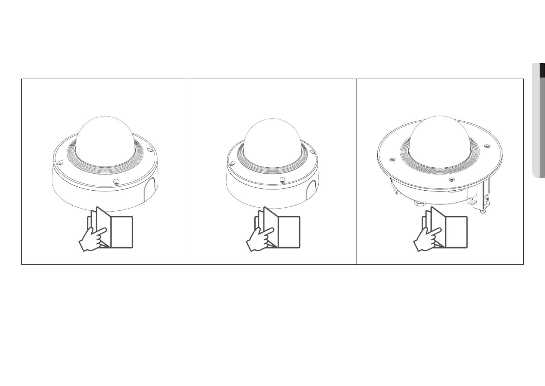
Outdoor Vandal Dome
XNV-6081/XNV-6081R/XNV-8081R
Indoor Vandal Dome
XND-6081V/XND-6081RV/XND-8081RV
Flush Mount Dome
XND-6081F/XND-6081RF/XND-8081RF
8 17 25
8_ outdoor vandal dome
outdoor vandal dome
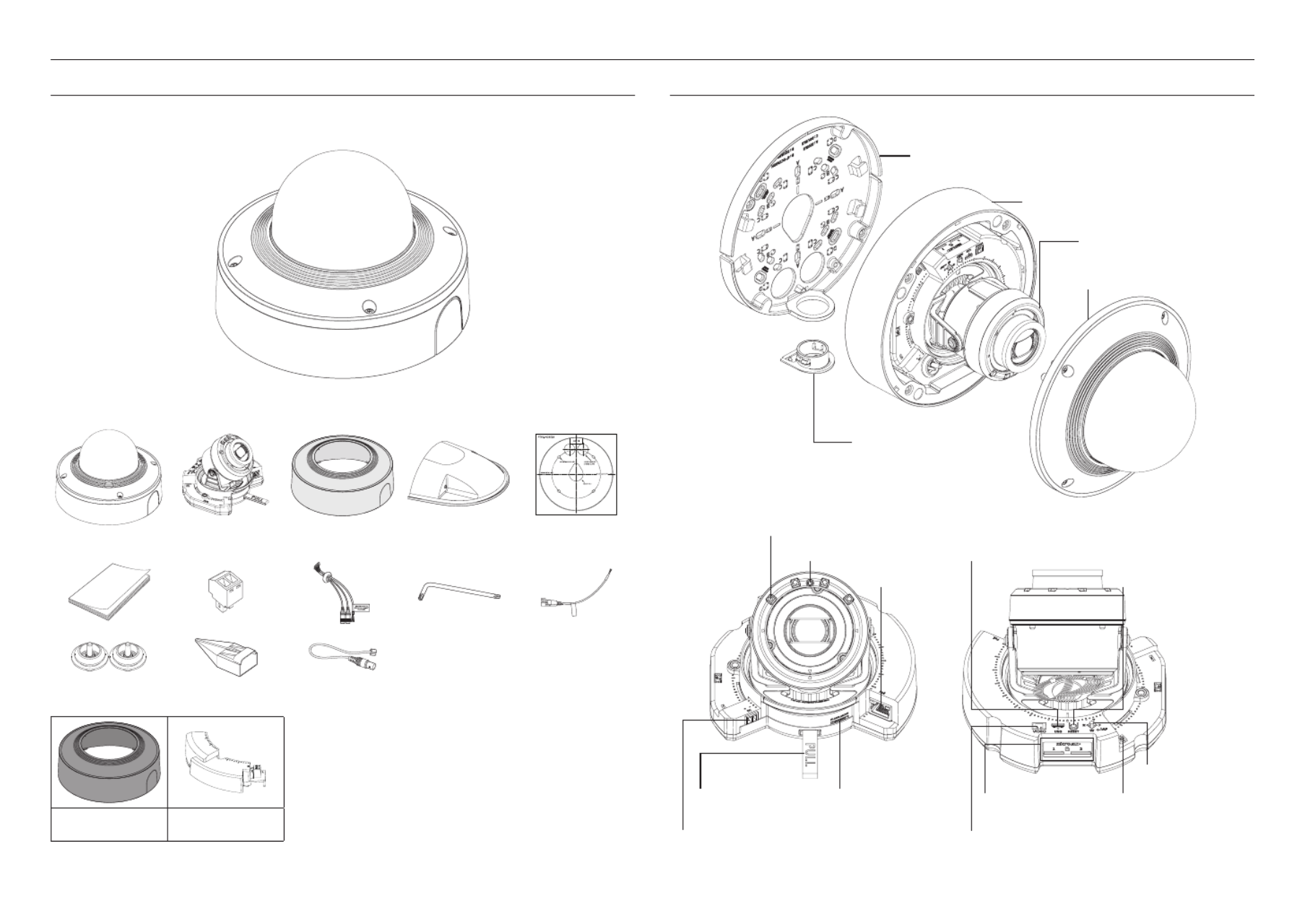
WHAT’S INCLUDED
As for each sales country, accessories are not the same.
<XNV-6081/XNV-6081R/XNV-8081R>
Color : Ivory
CAUTION: Be ware of the Rated Voltage and Polari ty
of the power conn ection .
Option (sold separately)
SBC-180B
(Color : Black) SPC-100AC
AT A GLANCE
Pipe-cover
e
Dome-cover
d
Camera-module
c
Camera-case
b
Mount-plate
a
fIR LED
gIllumination Sensor iMicro USB terminal
jReset button
qZoom/Focus
Control Button
pAC 24 V power
connection terminal
oMicro SD card slot
nTest Monitor Out
kDC 12 V power
connection terminal
lSeparator strap mAudio & alarm
cable connection
terminal
hNetwork
connection
terminal

English _9
●● OUTDOOR VANDAL DOME
INSTALLATION
J
`This camera is waterproof and in compliance with the IP67 / IP66 spec, but the jack connected to the external cable is not.
You are recommended to install this product below the edge of eaves to prevent the cable from being externally exposed.
Precautions before installation
Ensure you read out the following instructions before installing the camera:
• Select an installation site that can hold at least 5 times the camera’s weight.
• Stuck-in or peeled-off cables can cause damage to the product or a fire.
• For safety purposes, keep anyone else away from the installation site.
And put aside personal belongings from the site, just in case.
• If the product is installed with excessive force, it may cause damage to the camera due to malfunction.
Forcing assembly using non-compliant tools may damage the product.
Removal
1. Peel off the tape fixing the camera case.
2. Take off the cushion protecting the camera lens.
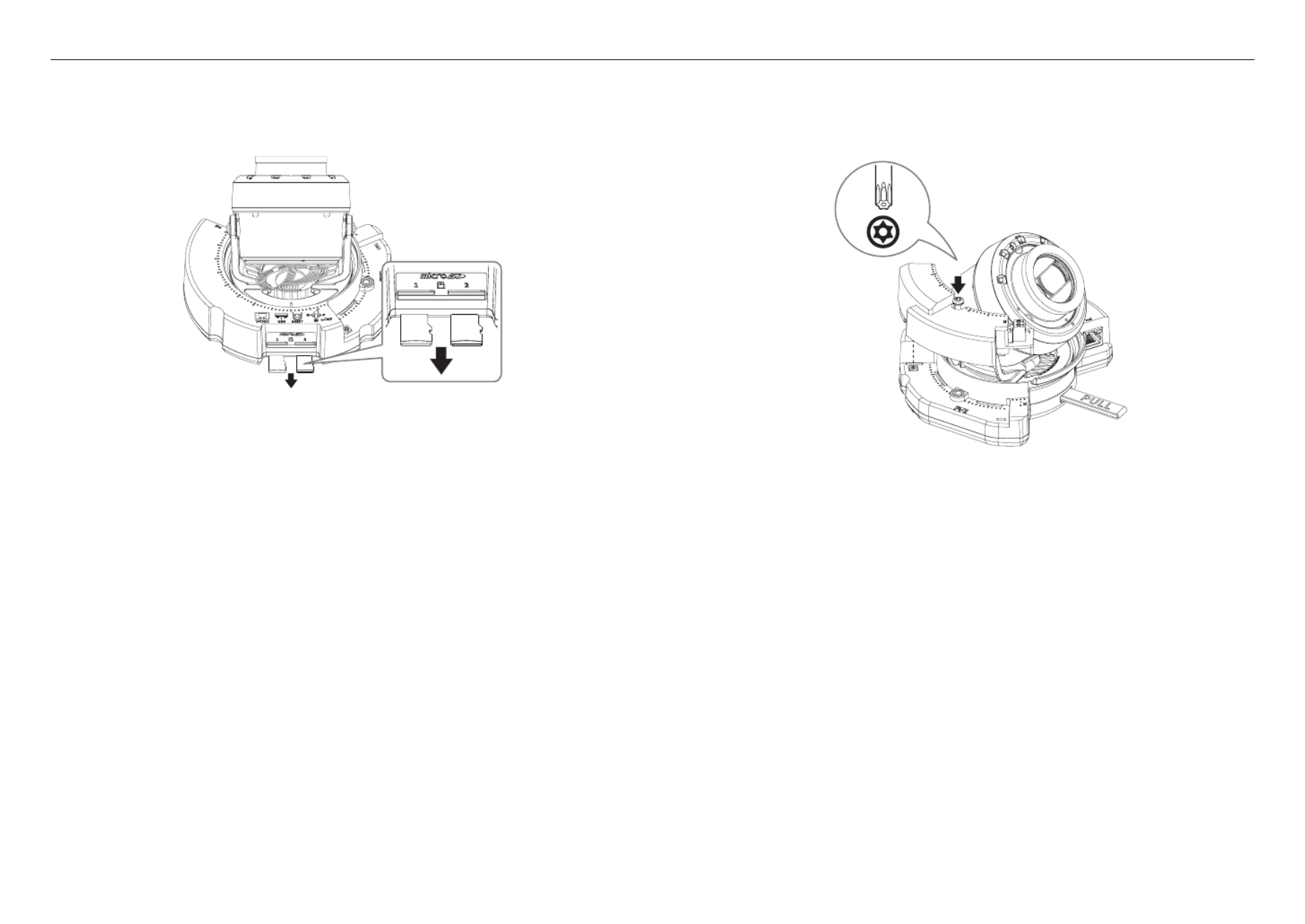
Inserting a Micro SD Memory Card
Slide the Micro SD card into the Micro SD slot on the camera module in the direction of the arrow.
J
`Before installing the camera, the Micro SD memory card should be inserted while the power source and the body are
separated.
`Do not forcefully insert it in the reverse direction. It might damage your Micro SD memory card and your product.
`
When it rains or the humidity is high, insertion or ejection of a Micro SD card is not recommended.
`
When installing/removing the Micro SD memory card, make sure you put the product body on a flat ground before working
in order to prevent accidents due to loss or drop of any parts.
10_ outdoor vandal dome
outdoor vandal dome
Removing a Micro SD Memory Card
Gently press down on the exposed end of the memory card as shown in the diagram to eject the memory
card from the slot.
J
`Please note that if you firmly push and release the Micro SD memory card when it is ejected, it may pop out.
`Before removing the Micro SD memory card, in < >, set the device to < > and press the [ ] button and turn Storage Off Apply
the camera off.
`If you turn off the camera or remove the Micro SD memory card that contains data from the product, the data may be lost or
damaged.
Installing the AC module (sold separately: SPC-100AC)
1. Install the AC module as shown in the figure.
2. Tighten the screw using the hex key.
x4
1x
TR20

English _11
●● OUTDOOR VANDAL DOME
Installation (mount plate)
[Directly installing on wall/ceiling]
1-1. Attach the installation template on the desired surface and drill holes for screws and cables.
1-2. Fix the mount plate using appropriate screws.
1-3. Pull out necessary cables among LAN/power/audio & alarm cables through the hole in the mount plate.
[Installing using pipe]
2-1. Attach the installation template and drill holes for screws and cables.
2-2. Separate the pipe cover of the mount plate by pressing its sides.

12_ outdoor vandal dome
outdoor vandal dome
2-3. Place the pipe on the mount plate.
2-4. Fix the mount plate using appropriate screws.
2-5. Pull out necessary cables among LAN/power/audio & alarm cables through the pipe.
Installation (camera case)
J
`Use a cable bush compliant with the LAN cable to be connected.
- Camera main: use a cable with the diameter of Ø5 to 6.5
- Components: use a cable with the diameter of Ø5 to 8.5
[Installing LAN/power cables]
1-1. Pull off the extruded parts of the bush to be used.
1-2. Route the LAN cable through the big hole of the bush and connect to the LAN connector.
1-3. (When using the power) Route the power cable through the small hole of the bush and connect it to the
provided terminal block.
1-4. Mount the bush to the camera case.
[Installing the LAN cable] (IP66)
2-1. Pull off the extruded part of the 1-hole bush provided.
2-2. Use the cap installer to pass through the RJ45 cable.
Cap Installer

English _13
●● OUTDOOR VANDAL DOME
2-3. Mount the bush to the camera case.
[Installing audio & alarm cables]
3-1. Mount the bush of the provided audio & alarm cables to the camera case.
4. Join the mount plate with the camera case.
x4
2x
TR20

14_ outdoor vandal dome
outdoor vandal dome
Installing the camera module
1. Connect the LAN/power/audio & alarm cables to the camera module terminal.
2. Attach the camera module to the case.
J
`A magnet is embedded at the bottom of the module
`Take caution not to allow any foreign objects between the attaching surfaces.
* AC
3. Adjust the lens to the desired direction with reference to “Adjusting the monitoring direction for the
camera” section. (page 33)
Assembling the dome cover
[Directly installing on wall/ceiling]
1. Assemble the dome cover.
J
`Make sure to firmly tighten the fastening screws so that there is no water damage issue.
`Be careful when using the AC module as the dome cover has a certain working direction.
x4
4x
TR20
J
`Be careful not to alter the monitoring direction of your camera.
English _15
●● OUTDOOR VANDAL DOME
[Using Weather cap]
1. Remove the screws from the dome cover.
2x
TR20
2. Assemble the dome cover.
3. Mount the weather cap to the dome cover and fasten the screws.
J
`Make sure to firmly tighten the fastening screws so that there is no water damage issue.
2x
TR20
Using/Removing Skin cover
1. Put on the skin cover in alignment with the pipe cover.
2. For a camera connected with a pipe, remove the pipe cover from the skin cover first before putting it on.

16_ outdoor vandal dome
outdoor vandal dome
3. To remove the skin cover, pull it while turning it clockwise as shown in the figure.
J
`Repetitive installation and removal of the skin cover may deform the skin cover.
`Installation and removal of the skin cover with excessive force may cause scratches on the surface of the product.
J
`When pipe is connected, release it using an appropriate tool.
Outdoor installation
When you install it outside of the building, please waterproof it with waterproof butyl rubber tape (can be
purchased in stores) so that water does not leak from the gap of the cable connected to the outside.
1. Connect the power, I/O, and LAN cables.
2. Wrap the black cable jacket (Area A) and the cable connection area with waterproof (butyl rubber) tape so
that more than half of the butyl rubber tape is overlapped.
Ca erm a
Ca erm a
Ca erm a
S temys
S temys
S temys
AA
J
`If the cable jacket is not waterproofed properly, then it can directly cause leakage. Make sure to protect the cable with a
dense layer of taping.
`Waterproof butyl tape is made of butyl rubber that can be stretched to twice its normal length.
English _17
●● INDOOR VANDAL DOME
WHAT’S INCLUDED
As for each sales country, accessories are not the same.
<XND-6081V/XND-6081RV/XND-8081RV>
Color : Ivory
CAUTION : Be ware of the Rated Voltag e a nd Pol ari ty
of the power co nn ec tion .
Option (sold separately)
SBC-160B
(Color : Black)
AT A GLANCE
Mount-plate
b
Pipe-cover
a
Camera-case
c
Camera-module
d
Dome-cover
e
fIR LED
gIllumination Sensor iMicro USB terminal
jReset button
q
Microphone
cable connection
terminal
pZoom/Focus
Control Button
oMicro SD card slot
nTest Monitor Out
kDC 12 V power
connection terminal
lSeparator strap mAudio & alarm
cable connection
terminal
hNetwork
connection
terminal
indoor vandal dome

18_ indoor vandal dome
indoor vandal dome
INSTALLATION
J
`This camera is waterproof and in compliance with the IP52 spec, but the jack connected to the external cable is not. You are
recommended to install this product below the edge of eaves to prevent the cable from being externally exposed.
Precautions before installation
Ensure you read out the following instructions before installing the camera:
•Select an installation site that can hold at least 5 times the camera’s weight.
•Stuck-in or peeled-off cables can cause damage to the product or a fire.
•For safety purposes, keep anyone else away from the installation site.
And put aside personal belongings from the site, just in case.
•If the product is installed with excessive force, it may cause damage to the camera due to malfunction.
Forcing assembly using non-compliant tools may damage the product.
Removal
1. Peel off the tape fixing the camera case.
2. Take off the cushion protecting the camera lens.
Inserting a Micro SD Memory Card
Slide the Micro SD card into the Micro SD slot on the camera module in the direction of the arrow.
J
`Before installing the camera, the Micro SD memory card should be inserted while the power source and the body are
separated.
`Do not forcefully insert it in the reverse direction. It might damage your Micro SD memory card and your product.
`
When it rains or the humidity is high, insertion or ejection of a Micro SD card is not recommended.
`
When installing/removing the Micro SD memory card, make sure you put the product body on a flat ground before working on it
in order to prevent accidents due to loss or drop of any parts.

English _19
●●INDOOR VANDAL DOME
Removing a Micro SD Memory Card
Gently press down on the exposed end of the memory card as shown in the diagram to eject the memory
card from the slot.
J
`Please note that if you firmly push and release the Micro SD memory card when it is ejected, it may pop out.
`Before removing the Micro SD memory card, in < >, set the device to < > and press the [ ] button and turn Storage Off Apply
the camera off.
`If you turn off the camera or remove the Micro SD memory card that contains data from the product, the data may be lost or
damaged.
Installation (mount plate)
[Directly installing on wall/ceiling]
1-1. Attach the installation template on the desired surface and drill holes for screws and cables.
1-2. Fix the mount plate using appropriate screws.
1-3. Pull out necessary cables among LAN/power/audio & alarm cables through the hole in the mount plate.

20_ indoor vandal dome
indoor vandal dome
2-3. Place the pipe on the mount plate.
2-4. Fix the mount plate using appropriate screws.
2-5. Pull out necessary cables among LAN/power/audio & alarm cables through the pipe.
Installation (camera case)
J
`Use a cable bush compliant with the LAN cable to be connected.
-Camera main: use a cable with the diameter of Ø5 to 6.5
-Components: use a cable with the diameter of Ø5 to 8.5
[Installing LAN/power cables]
1-1. Pull off the extruded parts of the bush to be used.
1-2. Route the LAN cable through the big hole of the bush and connect to the LAN connector.
1-3. (When using the power) Route the power cable through the small hole of the bush and connect it to the
provided terminal block.
[Installing using pipe]
2-1. Attach the installation template and drill holes for screws and cables.
2-2. Separate the pipe cover of the mount plate by pressing its sides.

22_ indoor vandal dome
indoor vandal dome
Installing the camera module
1. Connect the LAN/power/audio & alarm cables to the camera module terminal.
2. Attach the camera module to the case.
J
`A magnet is embedded at the bottom of the module
`Take caution not to allow any foreign objects between the attaching surfaces.
3. Connect the microphone cable to the camera module.
4. Adjust the lens to the desired direction with reference to “Adjusting the monitoring direction for the
camera” section. (page 33)
[Installing audio & alarm cables]
3-1. Mount the bush of the provided audio & alarm cables to the camera case.
4. Join the mount plate with the camera case.
x4
2x
TR20

English _23
●● INDOOR VANDAL DOME
Assembling the dome cover
[Directly installing on wall/ceiling]
1. Assemble the dome cover.
J
`Make sure to firmly tighten the fastening screws so that there is no water damage issue.
x4
4x
TR20
J
`Be careful not to alter the monitoring direction of your camera.
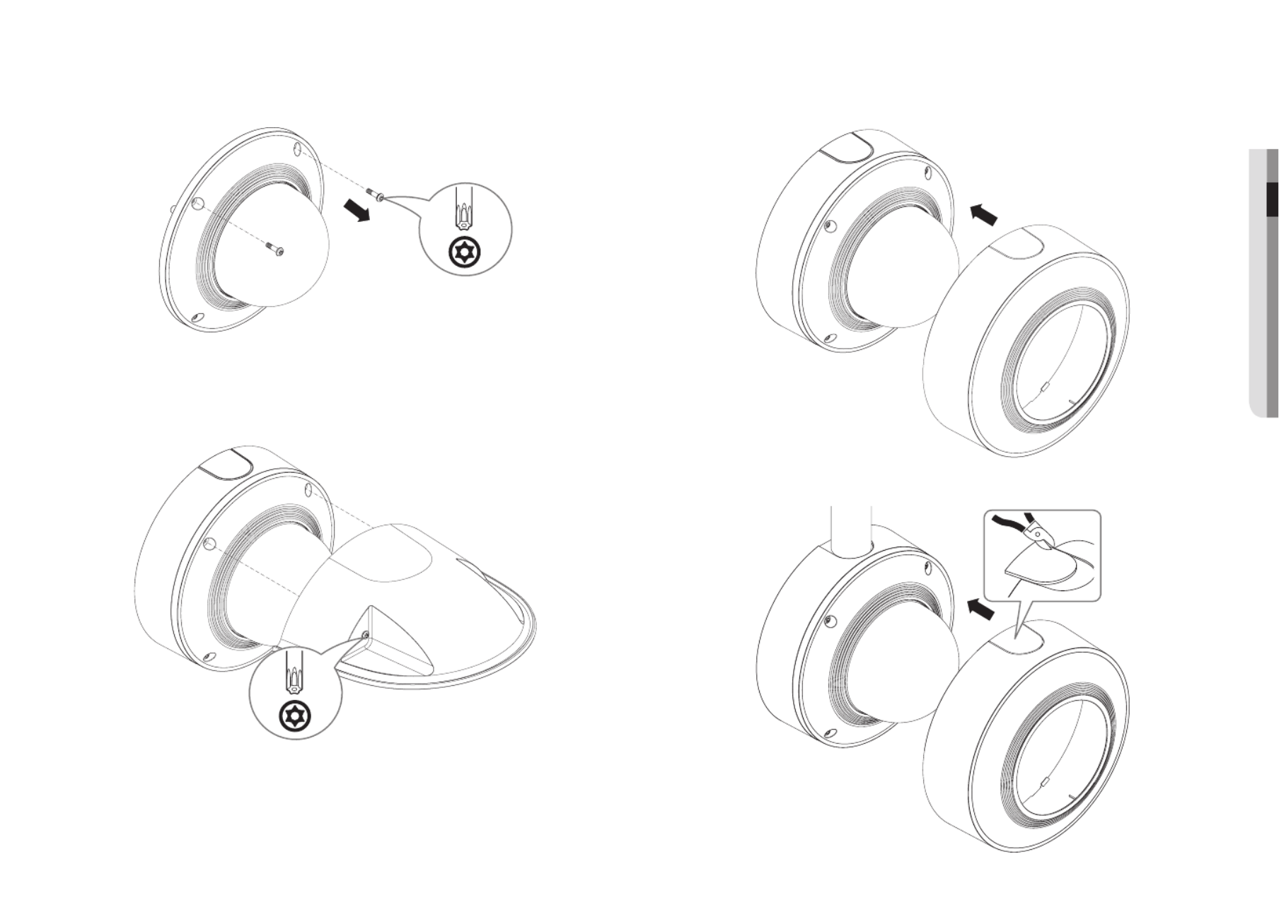
Using/Removing Skin cover
1. Put on the skin cover in alignment with the pipe cover.
2. For a camera connected with a pipe, remove the pipe cover from the skin cover first before putting it on.

24_ indoor vandal dome
indoor vandal dome
3. To remove the skin cover, pull it while turning it clockwise as shown in the figure.
J
`Repetitive installation and removal of the skin cover may deform the skin cover.
`Installation and removal of the skin cover with excessive force may cause scratches on the surface of the product.
J
`When pipe is connected, release it using an appropriate tool.
Outdoor installation
When you install it outside of the building, please waterproof it with waterproof butyl rubber tape (can be
purchased in stores) so that water does not leak from the gap of the cable connected to the outside.
1. Connect the power, I/O, and LAN cables.
2. Wrap the black cable jacket (Area A) and the cable connection area with waterproof (butyl rubber) tape so
that more than half of the butyl rubber tape is overlapped.
Ca erm a
Ca erm a
Ca erm a
S temys
S temys
S temys
AA
J
`If the cable jacket is not waterproofed properly, then it can directly cause leakage. Make sure to protect the cable with a
dense layer of taping.
`Waterproof butyl tape is made of butyl rubber that can be stretched to twice its normal length.

English _25
●●FLUSH MOUNT DOME
WHAT’S INCLUDED
As for each sales country, accessories are not the same.
<XND-6081F/XND-6081RF/XND-8081RF>
CAUTION : Be ware of the Rated Voltag e a nd Pol ari ty
of the power co nn ec tion .
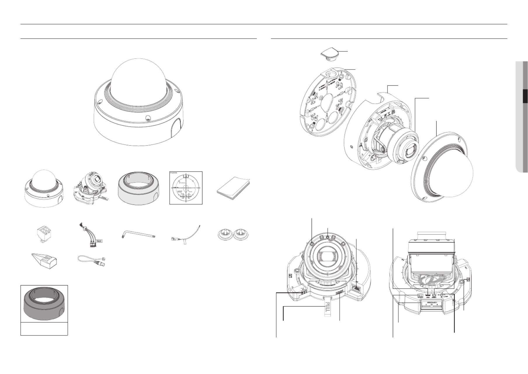
AT A GLANCE
Bracket
a
Housing
b
Camera-module
c
Dome-cover
d
fIR LED
gIllumination Sensor iMicro USB terminal
jReset button
pZoom/Focus
Control Button
oMicro SD card slot
nTest Monitor Out
kDC 12 V power
connection terminal
lSeparator strap mAudio & alarm
cable connection
terminal
hNetwork
connection
terminal
flush mount dome
English _27
●●FLUSH MOUNT DOME
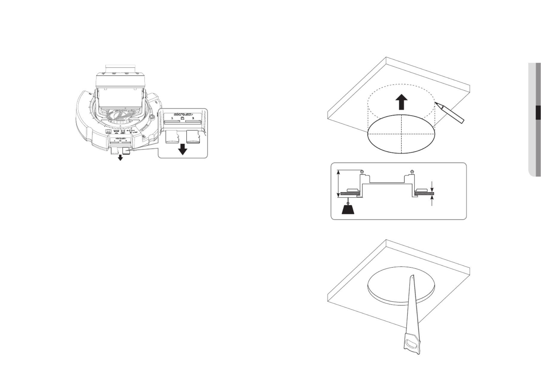
Removing a Micro SD Memory Card
Gently press down on the exposed end of the memory card as shown in the diagram to eject the memory
card from the slot.
J
`Please note that if you firmly push and release the Micro SD memory card when it is ejected, it may pop out.
`Before removing the Micro SD memory card, in < >, set the device to < > and press the [ ] button and turn Storage Off Apply
the camera off.
`If you turn off the camera or remove the Micro SD memory card that contains data from the product, the data may be lost or
damaged.
Installation (housing)
1. Attach the installation template to the ceiling and mark its location with a pencil.
Maximum 6.5 kg (14 Ib)
KG
More than 5 mm,
less than 60 mm
90 mm
2. Attach the installation template and drill holes.

28_ flush mount dome
flush mount dome
4-2. Pull out necessary cables among LAN/power/audio & alarm cables through the pipe.3. Connect the safety cable.
J
`A safety cable is not provided.
e.g.
[Using pipe]
4-1. Install the pipe in a fitting hole.
¾” NUT
½” NUT

English _29
●●FLUSH MOUNT DOME
Installation (camera case)
J
`Use a cable bush compliant with the LAN cable to be connected.
-Components: use a cable with the diameter of Ø5 to 8.5
[Installing LAN/power cables]
1-1. Pull off the extruded parts of the bush to be used.
1-2. Route the LAN cable through the big hole of the bush and connect to the LAN connector.
1-3. (When using the power) Route the power cable through the small hole of the bush and connect it to the
provided terminal block.
1-4. Mount the bush to the housing.
[Installing the LAN cable]
2-1. Pull off the extruded part of the 1-hole bush provided.
2-2. Use the cap installer to pass through the RJ45 cable.
Cap Installer
2-3. Mount the bush to the housing.
30_ flush mount dome
flush mount dome
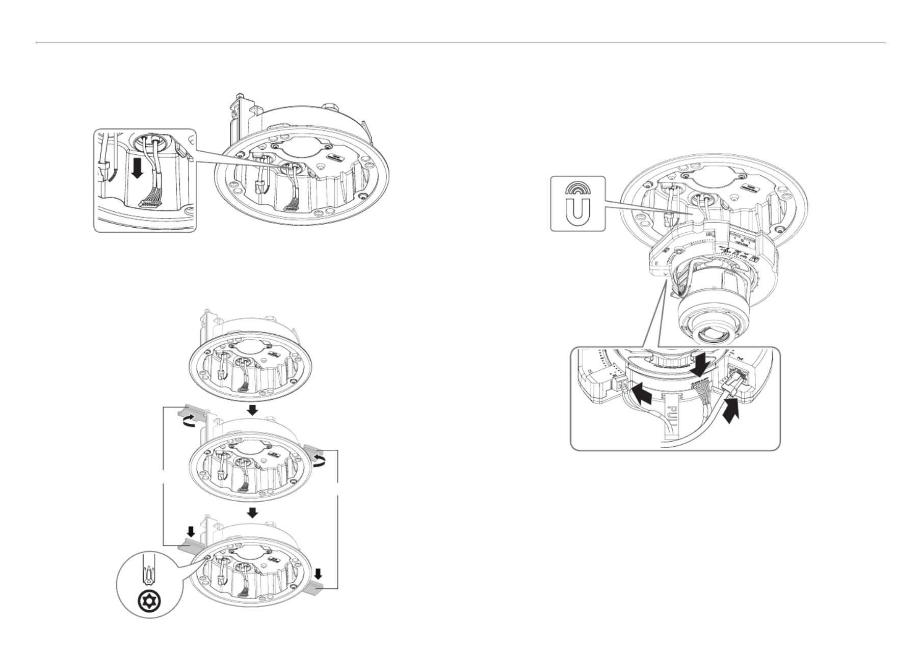
Installing the camera module
1. Connect the LAN/power/audio & alarm cables to the camera module terminal.
2. Attach the camera module to the case.
J
`A magnet is embedded at the bottom of the module
`Take caution not to allow any foreign objects between the attaching surfaces.
3. Adjust the lens to the desired direction with reference to “Adjusting the monitoring direction for the
camera” section. (page 33)
[Installing audio & alarm cables]
3-1. Mount the bush of the provided audio & alarm cables to the camera case.
4. Turn the screws on the housing to fix the housing to the ceiling.
J
`The bracket will fix the housing to the ceiling.
`Ensure that the housing is firmly fixed to the ceiling.
Bracket
Bracket
x4
2x
TR20
English _31
●●FLUSH MOUNT DOME
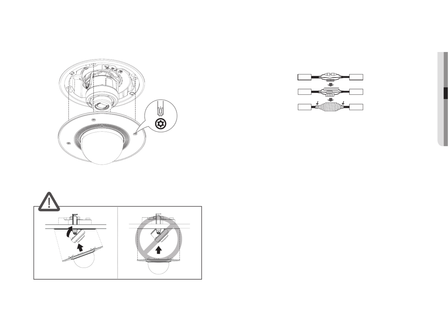
Assembling the dome cover
1. Assemble the dome cover.
J
`Make sure to firmly tighten the fastening screws so that there is no water damage issue.
x4
4x
TR20
J
`Be careful not to alter the monitoring direction of your camera.
Outdoor installation
When you install it outside of the building, please waterproof it with waterproof butyl rubber tape (can be
purchased in stores) so that water does not leak from the gap of the cable connected to the outside.
1. Connect the power, I/O, and LAN cables.
2. Wrap the black cable jacket (Area A) and the cable connection area with waterproof (butyl rubber) tape so
that more than half of the butyl rubber tape is overlapped.
Ca erm a
Ca erm a
Ca erm a
S temys
S temys
S temys
AA
J
`If the cable jacket is not waterproofed properly, then it can directly cause leakage. Make sure to protect the cable with a
dense layer of taping.
`Waterproof butyl tape is made of butyl rubber that can be stretched to twice its normal length.

32_ installation & connection
installation & connection
optionaL acceSSorieS for inStaLLation
You can purchase appropriate optional accessories available.
Hanging mount Hanging mount
Model Name SBP-187HMW SBP-167HMW
Compatible model XNV-6081/XNV-6081R/XNV-8081R XND-6081V/XND-6081RV/XND-8081RV
Wall mount Ceiling mount
Model Name SBP-300WMW1 SBP-300CMW
Compatible model SBP-180HMW/160HMW SBP-180HMW/160HMW
Corner mount Pole mount
Model Name SBP-300KMW SBP-300PMW
Compatible model SBP-300WMW1 SBP-300WMW1
Skin cover Skin cover
Model Name SBC-180B (Black) SBC-160B (Black)
Compatible model XNV-6081/XNV-6081R/XNV-8081R XND-6081V/XND-6081RV/XND-8081RV
AC24V power module
Model Name SPC-100AC
Compatible model XNV-6081/XNV-6081R/XNV-8081R

installation & connection
34_ installation & connection
Ethernet Connection
Connect the Ethernet cable to the local network or to the Internet.
Connecting WiFi
Camera Setup
1. Connect OTG adapter (5-pin) and WiFi dongle to the micro USB terminal.
Smartphone Setup
1. Install the Wisenet Installation application.
2. Select the camera SSID after turning on the WiFi.
3. Run the Wisenet Installation application.
4. When you log in to the camera, the video will be connected.
`The video will be played without being logged in during the initial connection.
5. You can adjust angle of view while watching the video through smartphone.
Recommended dongle manufacturer
Manufacturer Model
NETIS WF2123 n300
EDIMAX EW-7811Un
IP Time N100mini
TP-LINK TL-WN823N V1
ASUS USB-N13
NETGEAR WNA3100M
CONNECTING WITH OTHER DEVICE
SOFT
AP
Ethernet
Test Monitor Out
Power
WiFi dongle
* AC
J
`The CVBS out terminal of the product is provided for easier installation, and is not recommended for monitoring purposes.
`The Micro USB out terminal of the product is provided for easier installation, and is not recommended for monitoring
purposes.

English _35
●●INSTALLATION & CONNECTION
Power Supply
Use the screwdriver to connect each line (+, –) of the power cable to the corresponding power port of the
camera.
J
`If the power sources for PoE and DC 12 V are simultaneously turned on, the device power will be supplied by both of PoE and
DC 12 V.
-You can also use a router featuring PoE to supply power to the camera.
-Use PoE that is compliant with the IEEE 802.3af protocols.
`Be careful not to reverse the polarity when you connect the power cable.
`The AC power is available after purchasing an AC module (SPC-100AC).
-Models: XNV-6081/XNV-6081R/XNV-8081R
-If the power sources for PoE and AC 24 V are simultaneously turned on, the external power source (AC 24 V) will be
used.
-AC 24 V can be connected as non-polar.
`If you want to connect an external device, you must turn off the external device before proceeding.
`Connect the set and the adapter power line first, and then connect the power cable to the outlet on the wall.
Power Cable Specification for Each Model
Model Input power Wire Type (AWG) Cable Length (Max.)
XND-6081V/F
XND-6081RV/RF DC 12V #18 22m
#20 14m
XND-8081RV/RF DC 12V #18 20m
#20 13m
XNV-6081/6081R
DC 12V #18 22m
#20 14m
AC 24V #18 40m
#20 26m
XNV-8081R
DC 12V #18 20m
#20 13m
AC 24V #18 38m
#20 24m
Network Cable Specification
Item Contents Remark
Connector RJ45 (10/100BASE-T)
Ethernet 10/100BASE-T
Cable UTP Category 5e
Max Distance 100M
PoE Support IEEE 802.3af
Connecting to Audio Input/Output
Network
PC
Microphone
Speaker
Microphone
Microphone
Amp
Speaker
AmpSpeaker
1. Connect the AUDIO IN port of the camera with the microphone or LINE OUT port of the amplifier that the
microphone is connected to.
M
`You can use the internal microphone of the camera without an external microphone connection
(only applicable for XND-6081V/XND-6081RV/XND-8081RV).
2. Connect the AUDIO OUT port of the camera with the speaker or LINE IN port of the amplifier that the
speaker is connected to.
3. Check the specifications for audio input.
installation & connection
36_ installation & connection
•Audio Codec
- Audio In : G.711 PCM (Bit Rate: 64kbps / Sampling Frequency: 8kHz), G.726 ADPCM (Bit Rate:
16Kbps, 24Kbps, 32Kbps, 40Kbps / Sampling Frequency: 8kHz), AAC (Bit Rate: 48Kbps / Sampling
Frequency: 16kHz)
- Audio Out : G.711 PCM (Bit Rate: 64kbps / Sampling Frequency: 8kHz)
•Full duplex Audio
•Audio in (XND-6081V/XND-6081RV/XND-8081RV) : Selectable (microphone/Line-in/Built-in microphone),
Supported voltage: 2.5VDC (4mA), Input impedance: 2K Ohm
•Audio in (XND-6081F/XND-6081RF/XND-8081RF/XNV-6081/XNV-6081R/XNV-8081R) : Selectable
(microphone/Line-in), Supported voltage: 2.5VDC (4mA), Input impedance: 2K Ohm
•Audio out : Line-out (3.5mm mono jack), Maximum output: 1Vms
•Line out impedance : 600Ω
J
`In the case you access the web viewer and select an external microphone as the audio input sources in < > - Video & Audio
<Audio setup>, the following specifications are recommended:
-Frequency range: 40-16,000 Hz
-Impedance: 1,500 Ω
-Sensitivity: -40±3 dB (7.1-14.1 mV)
`In any of the following cases, sound classification performance may be degraded or malfunction:
-If gunshot sounds are heard continuously in a short interval (e.g. machine gun sound) rather than a one-time gunshot
sound
-If the noise is too loud for the noise and the target sound to be distinguished
-If two or more of different sounds are registered simultaneously
-If the sound classification is applied while using the noise removal function in a quiet place
-If the source of clapping sounds or screams is close to the camera (within 1 meter)
-If a sound that does not belong to any of the sound classification categories (airplanes sound, siren sound, etc.) is loudly
heard all of sudden
-If external microphone does not meet the recommended specifications
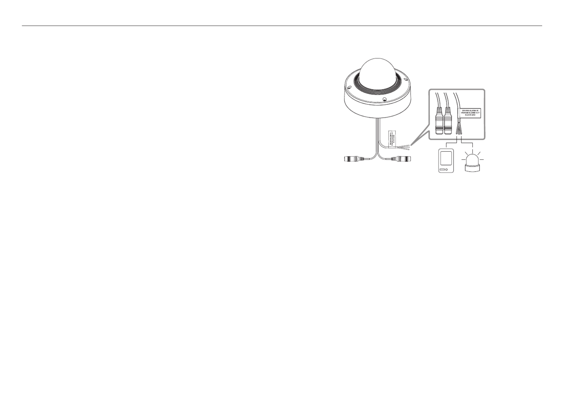
Connecting to the I/O port box
Connect the Alarm I/O cable to the corresponding port of the port box.
Alarm
(Warning lamp)
Sensor
•ALARM-IN : Used to connect the alarm input sensor.
•ALARM-OUT : Used to connect the alarm output signal.
•GND : Common port for alarm in/output signal.
J
`If devices (e.g., flashing light and siren) that exceed the voltage and current specifications are connected by using the open
collector method, it may cause malfunction.
Refer to the “ ” when connecting devices that exceed the voltage and current specifications. (page 37)Alarm Out Wiring Diagram
To connect the external sensor
Connect one strand of each signal line (2-strand) of the sensors to the [ ] port, and connect the ALARM IN
other strand to the [ ] port.GND

English _37
●●INSTALLATION & CONNECTION
Alarm In Wiring Diagram
Alarm Out Wiring Diagram
Sensor
GND
RESISTORALARM IN (5mA SINK)
RESISTOR RESISTOR
VCC_3.3V
DIODE
GND
MLCC TRANSISTOR
External
connection
Inside of the camera
Warning lamp /
Siren power
Warning lamp /
Siren
(
-
) (
+
)
ALARM OUT (12VDC 20mA MAX)
RESISTOR 10K ohm
DIODE
RELAY
DC 5V or 3.3V
TRANSISTOR
GND
GND
TRANSISTOR
External connection Inside of the camera
GND
RESISTOR

network connection and setup
38_ network connection and setup
network connection and setup
You can set up the network settings according to your network configurations.
CONNECTING THE CAMERA DIRECTLY TO LOCAL AREA NETWORKING
Connecting to the camera from a local PC in the LAN
1. Launch an Internet browser on the local PC.
2. Enter the IP address of the camera in the address bar of the browser.
M
`A remote PC in an external Internet out of the LAN network may not be able to connect to the camera installed in the intranet
if the port-forwarding is not properly set or a firewall is set.
In this case, to resolve the problem, contact your network administrator.
`In the IP installer, you can use the initial password, “ ” to set IP Address, Subnet Mask, Gateway, HTTP Port, VNP Port, IP 4321
type. After changing the network interface, for better security, access the web viewer and change the password.
`By factory default, the IP address will be assigned from the DHCP server automatically.
If there is no DHCP server available, the IP address will be set to 192.168.1.100.
To change the IP address, use the IP Installer.
For further details on IP Installer use, refer to “ ”. (Page 39)Static IP Setup
CONNECTING THE CAMERA DIRECTLY TO A DHCP BASED DSL/CABLE
MODEM
1. Connect the user PC directly with the network camera.
2. Run the IP Installer and change the IP address of the camera so that you can use the web browser on
your desktop to connect to the Internet.
3. Use the Internet browser to connect to the web viewer.
4. SetupMove to [ ] page.
5. Network DDNSMove to [ ] – [ ] and configure the DDNS settings.
6. Basic IP & Port DHCPMove to [ ] – [ ], and set the IP type to [ ].
7. Connect the camera, which was removed from your PC, directly to the modem.
8. Restart the camera.
M
`For information on how to set DDNS, refer to the online help of Web Viewer.
`For information on how to set the IP format, refer to the online help of Web Viewer.
<Local Network>
Camera
Camera
Local PC
INTERNET
External Remote PC
DDNS Server
(Data Center, KOREA)
Camera
External Remote PC
DDNS Server
(Data Center, KOREA)
DSL/Cable Modem
INTERNET
English _39
●● NETWORK CONNECTION AND SETUP
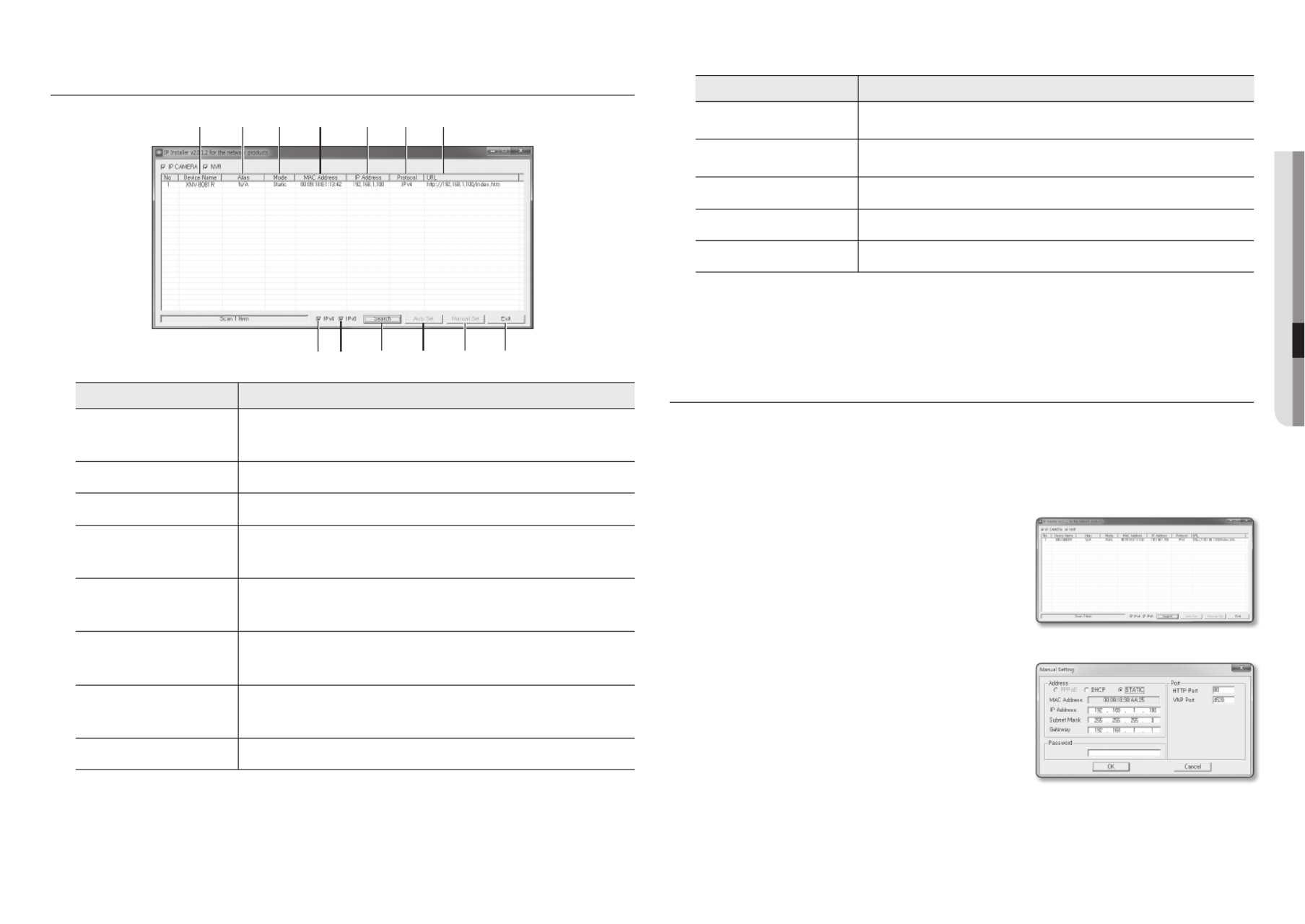
BUTTONS USED IN IP INSTALLER
Item Description
a
Device Name
Model name of the connected camera.
Click the column to sort the list by model name.
However, search will be stopped if clicked during the search.
b
Alias
This function is not currently implemented.
c
Mode
Displays either < > or < > for the current network connection status.Static Dynamic
d
MAC(Ethernet) Address
Ethernet address for the connected camera.
Click the column to sort the list by Ethernet address.
However, search will be stopped if clicked during the search.
e
IP Address
IP address.
Click the column to sort the list by IP address.
However, search will be stopped if clicked during the search.
f
Protocol
Network setting for the camera.
The factory default is “IPv4”.
Cameras with the IPv6 setting will be displayed “IPv6”.
g
URL
DDNS URL address enabling access from the external Internet.
However, this will be replaced with the < > of the camera if DDNS IP Address
registration has failed.
h
IPv4
Scans for cameras with the IPv4 setting.
Item Description
i
IPv6
Scans for cameras with the IPv6 setting.
Activated in an IPv6 compliant environment only.
j
Search
Scans for cameras that are currently connected to the network.
However, this button will be grayed out if neither IPv4 nor IPv6 is checked.
k
Auto Set
The IP Installer automatically configures the network settings.
l
Manual Set
You should configure the network settings manually.
m
Exit
Exits the IP Installer program.
M
`
Use the latest version of the IP installer. You can download the latest version from the Hanwha Techwin web site.
`If the supporting OS is Windows 8.1, it is recommended that you use the Wisenet Device Manager instead of the IP Wisen
The Wisenet Device Manager Program can be downloaded by visiting the Hanwha Techwin website (http://www.hanwha
security.com) under the menu <Technical Guides> - <Online Tool>.
STATIC IP SETUP
Manual Network Setup
Run < > to display the camera search list. IP Installer_v2.XX.exe
At the initial startup, both [ ] and [ ] will be grayed out.Auto Set Manual Set
M
`For cameras found with the IPv6 setting, these buttons will be grayed out as the cameras do not support this function.
1. Select a camera in the search list.
Check the MAC address of the camera on the camera’s label.
Both the [ ] and [ ] buttons will be Auto Set Manual Set
activated.
2. Manual SetClick [ ].
The Manual Setting dialog appears.
< >, < >, < >, <IP Address Subnet Mask Gateway HTTP
Port VNP Port>, and < > of the camera are displayed in the
preset values.
3. AddressIn the < > pane, provide the necessary information.
• MAC (Ethernet) Address : The MAC address imprinted on
the camera label is automatically displayed and requires no
user setting.
M
`IP related parameters can be set only when DHCP is not checked.
a b c d e f g
h i j k l m

network connection and setup
40_ network connection and setup
If not using a Broadband Router
For setting < >, < >, and < >, contact your network administrator.IP Address Subnet Mask Gateway
4. PortIn the < > pane, provide necessary information.
•HTTP Port : Used to access the camera using the Internet
browser, defaulted to 80.
•VNP Port : Used to control the video signal transfer,
defaulted to 4520.
5. Enter the password.
Enter the password of “ ” account, which was used to admin
access the camera.
J
`For the security purposes, you are recommended to use a combination of numbers, alphabets uppercase and lowercase and
special characters for your password.
`For information on how to change the password, refer to the online help of Web Viewer.
6. OKClick [ ].
Manual network setup will be completed.
If using a Broadband Router
•IP Address : Enter an address falling in the IP range provided
by the Broadband Router.
ex) 192.168.1.2~254, 192.168.0.2~254,
192.168.XXX.2~254
•Subnet Mask : The < > of the Broadband Router Subnet Mask
will be the < > of the camera.Subnet Mask
•Gateway : The < > of the Broadband Router Local IP Address
will be the < > of the camera.Gateway
M
`The settings may differ depending on the connected Broadband
Router model.
For more information, refer to the user manual of the applicable router.
`For more information about port forwarding of the broadband router, refer to “Port Range Forward (Port Mapping) Setup”.
(Page 41)
If the Broadband Router has more than one camera connected
Configure the IP related settings and the Port related settings distinctly with each other.
ex)
Category Camera #1 Camera #2
IP related settings
IP Address
Subnet Mask
Gateway
192.168.1.100
255.255.255.0
192.168.1.1
192.168.1.101
255.255.255.0
192.168.1.1
Port related settings
HTTP Port
VNP Port
8080
4520
8081
4521
M
`If the < > is set other than 80, you must provide the < > number in the address bar of the Internet browser HTTP Port Port
before you can access the camera.
ex) http://IP address : HTTP Port
http://192.168.1.100:8080
Auto Network Setup
Run < > to display the camera search list. IP Installer_v2.XX.exe
At the initial startup, both [ ] and [ ] will be grayed out.Auto Set Manual Set
M
`For cameras found with the IPv6 setting, these buttons will be grayed out as the cameras do not support this function.
1. Select a camera in the search list.
Check the MAC address of the camera on the camera’s label.
Both the [ ] and [ ] buttons will be Auto Set Manual Set
activated.
2. Auto SetClick [ ].
The Auto Setting dialog appears.
The < >, < >, and < > will IP Address Subnet Mask Gateway
be set automatically.
3. Enter the password.
Enter the password of “ ” account, which was used to admin
access the camera.
J
`For the security purposes, you are recommended to use a
combination of numbers, alphabets uppercase and lowercase and
special characters for your password.
`For information on how to change the password, refer to the online
help of Web Viewer.
4. OKClick [ ].
Auto network setup will be completed.
English _41
●●NETWORK CONNECTION AND SETUP
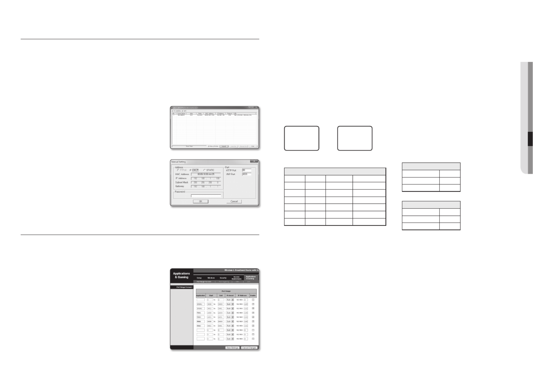
DYNAMIC IP SETUP
Dynamic IP Environment Setup
•Example of the Dynamic IP environment
- If a Broadband Router, with cameras connected, is assigned an IP address by the DHCP server
- If connecting the camera directly to modem using the DHCP protocols
- If IPs are assigned by the internal DHCP server via the LAN
Checking the Dynamic IP
1. Run the IP Installer on the user’s local computer.
Cameras allocated with < > address are shown in Dynamic IP
the list.
2. Select a camera from the search result.
3. Manual SetClick the [ ] button and check the camera’s
< > address. Dynamic IP
If you uncheck < >, you can change IP to < >.DHCP Static
PORT RANGE FORWARD (PORT MAPPING) SETUP
If you have installed a Broadband Router with a camera connected, you must set the port range forwarding on the
Broadband Router so that a remote PC can access the camera in it.
Manual Port Range Forwarding
1. From the Setup menu of the Broadband Router, select
< > - < >. Applications & Gaming Port Range Forward
For setting the port range forward for a third-party Broadband
Router, refer to the user guide of that Broadband Router.
2. TCP UDP PortSelect < > and < > for each connected camera
to the Broadband Router.
The number of each port to be configured to the IP router
should be set according to the port number designated
in < > - < > - < > on the camera web Setup Basic IP & Port
viewer.
3. Save SettingsWhen done, click [ ].
Your settings will be saved.
M
`Above sample instructions are based on the CISCO’s Broadband Router.
`The settings may differ depending on the connected Broadband Router model.
For more information, refer to the user manual of the applicable router.
Setting up Port Range Forward for several network cameras
•You can set a rule of Port Forwarding on the Broadband Router device through its configuration web page.
•A user can change each port using the camera setting screen.
When Camera1 and Camera2 are connected to a router :
M
`Port forwarding can be done without additional router setup if the router supports the UPnP (Universal Plug and Play) function.
After connecting the network camera, select the checkbox from the menu < > in < > in Quick connect Wisenet DDNS
“Settings -> -> Network DDNS”.
User Internet
Broadband Router
Start End Protocol IP Address
3000 3000 TCP/UDP 192.168.1.100
3001 3001 TCP/UDP 192.168.1.101
4520 4520 TCP/UDP 192.168.1.100
4521 4521 TCP/UDP 192.168.1.101
8080 8080 TCP/UDP 192.168.1.100
8081 8081 TCP/UDP 192.168.1.101
Camera1 (192.168.1.100)
HTTP port 8080
Device port 4520
RTSP port 3000
Camera2 (192.168.1.101)
HTTP port 8081
Device port 4521
RTSP port 3001
Produkt Specifikationer
| Mærke: | Hanwha |
| Kategori: | Overvågningskamera |
| Model: | XND-6081V |
Har du brug for hjælp?
Hvis du har brug for hjælp til Hanwha XND-6081V stil et spørgsmål nedenfor, og andre brugere vil svare dig
Overvågningskamera Hanwha Manualer

24 September 2024
24 September 2024
24 September 2024
1 September 2024
31 August 2024
30 August 2024
30 August 2024
30 August 2024
30 August 2024
30 August 2024
Overvågningskamera Manualer
- Overvågningskamera Bosch
- Overvågningskamera Denver
- Overvågningskamera Sony
- Overvågningskamera Canon
- Overvågningskamera Netis
- Overvågningskamera Samsung
- Overvågningskamera Panasonic
- Overvågningskamera Extech
- Overvågningskamera Moog
- Overvågningskamera TP-Link
- Overvågningskamera Philips
- Overvågningskamera Vitek
- Overvågningskamera Gigaset
- Overvågningskamera Pioneer
- Overvågningskamera Mitsubishi
- Overvågningskamera Braun
- Overvågningskamera Logitech
- Overvågningskamera Emos
- Overvågningskamera Google
- Overvågningskamera Technaxx
- Overvågningskamera HP
- Overvågningskamera Waeco
- Overvågningskamera Garmin
- Overvågningskamera Sanyo
- Overvågningskamera Grundig
- Overvågningskamera D-Link
- Overvågningskamera Arlo
- Overvågningskamera Motorola
- Overvågningskamera Asus
- Overvågningskamera Toshiba
- Overvågningskamera Pyle
- Overvågningskamera Kodak
- Overvågningskamera Furrion
- Overvågningskamera InFocus
- Overvågningskamera Nedis
- Overvågningskamera Friedland
- Overvågningskamera Abus
- Overvågningskamera Planet
- Overvågningskamera Adj
- Overvågningskamera Hama
- Overvågningskamera Creative
- Overvågningskamera Thomson
- Overvågningskamera Belkin
- Overvågningskamera Edimax
- Overvågningskamera Burg Wächter
- Overvågningskamera Clas Ohlson
- Overvågningskamera DataVideo
- Overvågningskamera Strong
- Overvågningskamera TRENDnet
- Overvågningskamera Smartwares
- Overvågningskamera Trevi
- Overvågningskamera Trust
- Overvågningskamera Laserliner
- Overvågningskamera Blaupunkt
- Overvågningskamera JVC
- Overvågningskamera Honeywell
- Overvågningskamera Uniden
- Overvågningskamera Buffalo
- Overvågningskamera Linksys
- Overvågningskamera Megasat
- Overvågningskamera Cisco
- Overvågningskamera EZVIZ
- Overvågningskamera König
- Overvågningskamera Elro
- Overvågningskamera Gembird
- Overvågningskamera Powerfix
- Overvågningskamera Alpine
- Overvågningskamera Netgear
- Overvågningskamera Maginon
- Overvågningskamera Yale
- Overvågningskamera Withings
- Overvågningskamera Nest
- Overvågningskamera Kerbl
- Overvågningskamera Vtech
- Overvågningskamera Exibel
- Overvågningskamera Genie
- Overvågningskamera Vaddio
- Overvågningskamera Bresser
- Overvågningskamera Western Digital
- Overvågningskamera Anker
- Overvågningskamera Digitus
- Overvågningskamera Zebra
- Overvågningskamera Jensen
- Overvågningskamera Alecto
- Overvågningskamera Flamingo
- Overvågningskamera Rollei
- Overvågningskamera Olympia
- Overvågningskamera Xiaomi
- Overvågningskamera Niceboy
- Overvågningskamera Aiptek
- Overvågningskamera Schneider
- Overvågningskamera B/R/K
- Overvågningskamera Marmitek
- Overvågningskamera Tesla
- Overvågningskamera Imou
- Overvågningskamera Ricoh
- Overvågningskamera Nexxt
- Overvågningskamera Aida
- Overvågningskamera APC
- Overvågningskamera Foscam
- Overvågningskamera Lorex
- Overvågningskamera Ikan
- Overvågningskamera Velleman
- Overvågningskamera LevelOne
- Overvågningskamera Marshall
- Overvågningskamera FLIR
- Overvågningskamera Perel
- Overvågningskamera Swann
- Overvågningskamera Vivotek
- Overvågningskamera Joblotron
- Overvågningskamera JUNG
- Overvågningskamera ORNO
- Overvågningskamera Binatone
- Overvågningskamera ZyXEL
- Overvågningskamera Fortinet
- Overvågningskamera Netatmo
- Overvågningskamera Tenda
- Overvågningskamera Eufy
- Overvågningskamera Ring
- Overvågningskamera M-e
- Overvågningskamera Overmax
- Overvågningskamera Somfy
- Overvågningskamera Y-cam
- Overvågningskamera Hikvision
- Overvågningskamera Monacor
- Overvågningskamera ION
- Overvågningskamera Raymarine
- Overvågningskamera Ubiquiti Networks
- Overvågningskamera AVerMedia
- Overvågningskamera EnGenius
- Overvågningskamera Reolink
- Overvågningskamera Grandstream
- Overvågningskamera Trebs
- Overvågningskamera EVE
- Overvågningskamera Renkforce
- Overvågningskamera Marshall Electronics
- Overvågningskamera Manhattan
- Overvågningskamera SPC
- Overvågningskamera Caliber
- Overvågningskamera Pentatech
- Overvågningskamera Switel
- Overvågningskamera AVtech
- Overvågningskamera LogiLink
- Overvågningskamera Orion
- Overvågningskamera Eminent
- Overvågningskamera Kramer
- Overvågningskamera QSC
- Overvågningskamera Brilliant
- Overvågningskamera Lanberg
- Overvågningskamera Hive
- Overvågningskamera Siedle
- Overvågningskamera BirdDog
- Overvågningskamera Evolveo
- Overvågningskamera Genius
- Overvågningskamera KJB Security Products
- Overvågningskamera Valueline
- Overvågningskamera Provision-ISR
- Overvågningskamera Quantum
- Overvågningskamera Axis
- Overvågningskamera ACTi
- Overvågningskamera CRUX
- Overvågningskamera Avanti
- Overvågningskamera Vimar
- Overvågningskamera Aluratek
- Overvågningskamera Dahua Technology
- Overvågningskamera Chacon
- Overvågningskamera SereneLife
- Overvågningskamera ZKTeco
- Overvågningskamera AG Neovo
- Overvågningskamera Stabo
- Overvågningskamera EtiamPro
- Overvågningskamera First Alert
- Overvågningskamera Speco Technologies
- Overvågningskamera Boss
- Overvågningskamera Broan
- Overvågningskamera Conceptronic
- Overvågningskamera Avidsen
- Overvågningskamera Crestron
- Overvågningskamera Lindy
- Overvågningskamera Kogan
- Overvågningskamera AVMATRIX
- Overvågningskamera Delta Dore
- Overvågningskamera Promise Technology
- Overvågningskamera Sitecom
- Overvågningskamera DiO
- Overvågningskamera Minox
- Overvågningskamera Intellinet
- Overvågningskamera V-TAC
- Overvågningskamera Qian
- Overvågningskamera August
- Overvågningskamera IDIS
- Overvågningskamera Geovision
- Overvågningskamera Schwaiger
- Overvågningskamera Steren
- Overvågningskamera Elmo
- Overvågningskamera AViPAS
- Overvågningskamera UniView
- Overvågningskamera Equip
- Overvågningskamera Alfatron
- Overvågningskamera REVO
- Overvågningskamera Aqara
- Overvågningskamera Ernitec
- Overvågningskamera Setti+
- Overvågningskamera BZBGear
- Overvågningskamera PTZ Optics
- Overvågningskamera AVer
- Overvågningskamera Ferguson
- Overvågningskamera Moxa
- Overvågningskamera Inovonics
- Overvågningskamera Bea-fon
- Overvågningskamera Profile
- Overvågningskamera WyreStorm
- Overvågningskamera Allnet
- Overvågningskamera Aldi
- Overvågningskamera Airlive
- Overvågningskamera Aritech
- Overvågningskamera ACME
- Overvågningskamera KlikaanKlikuit
- Overvågningskamera Marquant
- Overvågningskamera Ednet
- Overvågningskamera Lumens
- Overvågningskamera Hombli
- Overvågningskamera Naxa
- Overvågningskamera Miniland
- Overvågningskamera Xavax
- Overvågningskamera Gira
- Overvågningskamera Interlogix
- Overvågningskamera DSC
- Overvågningskamera Boyo
- Overvågningskamera Iget
- Overvågningskamera EverFocus
- Overvågningskamera Adesso
- Overvågningskamera Satel
- Overvågningskamera Notifier
- Overvågningskamera Monoprice
- Overvågningskamera Beafon
- Overvågningskamera Chuango
- Overvågningskamera MicroView
- Overvågningskamera ETiger
- Overvågningskamera Videcon
- Overvågningskamera INSTAR
- Overvågningskamera Advantech
- Overvågningskamera Digital Watchdog
- Overvågningskamera Moen
- Overvågningskamera Ganz
- Overvågningskamera MEE Audio
- Overvågningskamera Mobotix
- Overvågningskamera Kwikset
- Overvågningskamera Ikegami
- Overvågningskamera Leviton
- Overvågningskamera Pelco
- Overvågningskamera Approx
- Overvågningskamera ClearOne
- Overvågningskamera Ebode
- Overvågningskamera Oplink
- Overvågningskamera Dorr
- Overvågningskamera Sonic Alert
- Overvågningskamera Linear PRO Access
- Overvågningskamera Summer Infant
- Overvågningskamera SMC
- Overvågningskamera Topica
- Overvågningskamera Iiquu
- Overvågningskamera Verint
- Overvågningskamera Brinno
- Overvågningskamera Rostra
- Overvågningskamera Caddx
- Overvågningskamera Spyclops
- Overvågningskamera EKO
- Overvågningskamera Kguard
- Overvågningskamera Woonveilig
- Overvågningskamera Accsoon
- Overvågningskamera Mobi
- Overvågningskamera Surveon
- Overvågningskamera Hollyland
- Overvågningskamera Epcom
- Overvågningskamera Indexa
- Overvågningskamera Lutec
- Overvågningskamera Whistler
- Overvågningskamera ClearView
- Overvågningskamera VideoComm
- Overvågningskamera IMILAB
- Overvågningskamera 3xLOGIC
- Overvågningskamera Inkovideo
- Overvågningskamera Weldex
- Overvågningskamera SecurityMan
- Overvågningskamera Mach Power
- Overvågningskamera Canyon
- Overvågningskamera CNB Technology
- Overvågningskamera Tapo
- Overvågningskamera Aigis
- Overvågningskamera Exacq
- Overvågningskamera Brickcom
- Overvågningskamera Laxihub
- Overvågningskamera Securetech
- Overvågningskamera EFB Elektronik
- Overvågningskamera NetMedia
- Overvågningskamera Videotec
- Overvågningskamera Illustra
- Overvågningskamera Atlona
- Overvågningskamera Nivian
- Overvågningskamera Arenti
- Overvågningskamera E-bench
- Overvågningskamera Blow
- Overvågningskamera Syscom
- Overvågningskamera Tecno
- Overvågningskamera Night Owl
- Overvågningskamera Guardzilla
- Overvågningskamera Astak
- Overvågningskamera Blink
- Overvågningskamera Milestone Systems
- Overvågningskamera Zavio
- Overvågningskamera Campark
- Overvågningskamera IPX
- Overvågningskamera Dedicated Micros
- Overvågningskamera Hamlet
- Overvågningskamera Annke
- Overvågningskamera Qoltec
- Overvågningskamera Digimerge
- Overvågningskamera Feelworld
- Overvågningskamera Wisenet
- Overvågningskamera Infortrend
- Overvågningskamera Epiphan
- Overvågningskamera HiLook
- Overvågningskamera Compro
- Overvågningskamera Vimtag
- Overvågningskamera Sonoff
- Overvågningskamera Gewiss
- Overvågningskamera Alula
- Overvågningskamera Insteon
- Overvågningskamera Costar
- Overvågningskamera ALC
- Overvågningskamera Security Labs
- Overvågningskamera Comtrend
- Overvågningskamera Seneca
- Overvågningskamera Avigilon
- Overvågningskamera American Dynamics
- Overvågningskamera Vosker
- Overvågningskamera Sentry360
- Overvågningskamera Owltron
- Overvågningskamera Petcube
- Overvågningskamera Enabot
- Overvågningskamera Luis Energy
- Overvågningskamera Sir Gawain
- Overvågningskamera VisorTech
- Overvågningskamera Atlantis Land
- Overvågningskamera B & S Technology
- Overvågningskamera I3International
- Overvågningskamera Ecobee
- Overvågningskamera Turing
- Overvågningskamera Wasserstein
- Overvågningskamera Qolsys
- Overvågningskamera Control4
- Overvågningskamera Milesight
- Overvågningskamera GVI Security
- Overvågningskamera Conbrov
- Overvågningskamera HuddleCamHD
- Overvågningskamera Defender
- Overvågningskamera IOIO
- Overvågningskamera BIRDFY
- Overvågningskamera I-PRO
- Overvågningskamera DVDO
- Overvågningskamera TCP
- Overvågningskamera Bolin Technology
- Overvågningskamera Nextech
- Overvågningskamera Tuya
- Overvågningskamera Bolide
- Overvågningskamera Telycam
- Overvågningskamera Arecont Vision
- Overvågningskamera Schlage
Nyeste Overvågningskamera Manualer
7 April 2025
7 April 2025
6 April 2025
29 Marts 2025
28 Marts 2025
20 Marts 2025
20 Marts 2025
20 Marts 2025
13 Marts 2025
8 Marts 2025