Hanwha XNV-6120 Manual
Hanwha
Overvågningskamera
XNV-6120
Læs nedenfor 📖 manual på dansk for Hanwha XNV-6120 (77 sider) i kategorien Overvågningskamera. Denne guide var nyttig for 9 personer og blev bedømt med 4.5 stjerner i gennemsnit af 2 brugere
Side 1/77

NETWORK CAMERA
User Manual
XNO-6120R/XNV-6120/XNV-6120R

Copyright
©2017 Hanwha Techwin Co., Ltd. All rights reserved.
Trademark
Each of trademarks herein is registered. The name of this product and other trademarks mentioned in this manual are the registered trademark of their
respective company.
Restriction
Copyright of this document is reserved. Under no circumstances, this document shall be reproduced, distributed or changed, partially or wholly, without
formal authorization.
Disclaimer
Hanwha Techwin makes the best to verify the integrity and correctness of the contents in this document, but no formal guarantee shall be
provided. Use of this document and the subsequent results shall be entirely on the user’s own responsibility. Hanwha Techwin reserves the
right to change the contents of this document without prior notice.
Design and specications are subject to change without prior notice.
The initial administrator ID is “admin” and the password should be set when logging in for the rst time.
Please change your password every three months to safely protect personal information and to prevent the damage of the information
theft.
Please, take note that it’s a user’s responsibility for the security and any other problems caused by mismanaging a password.
Network Camera
User Manual
English _3
●●overview
important Safety inStructionS
1. Read these instructions.
2. Keep these instructions.
3. Heed all warnings.
4. Follow all instructions.
5. Do not use this apparatus near water.
6. Clean the contaminated area on the product surface with a soft, dry cloth or a damp cloth.
(Do not use a detergent or cosmetic products that contain alcohol, solvents or surfactants or oil constituents
as they may deform or cause damage to the product.)
7. Do not block any ventilation openings, Install in accordance with the manufacturer’s instructions.
8. Do not install near any heat sources such as radiators, heat registers, stoves, or other apparatus (including
amplifiers) that produce heat.
9. Do not defeat the safety purpose of the polarized or grounding-type plug. A polarized plug has two blades
with one wider than the other. A grounding type plug has two blades and a third grounding prong. The wide
blade or the third prong are provided for your safety. If the provided plug does not fit into your outlet, consult
an electrician for replacement of the obsolete outlet.
10. Protect the power cord from being walked on or pinched particularly at plugs, convenience receptacles, and
the point where they exit from the apparatus.
11. Only use attachments/ accessories specified by the manufacturer.
12. Use only with the cart, stand, tripod, bracket, or table specified by the manufacturer,
or sold with the apparatus. When a cart is used, use caution when moving the cart/
apparatus combination to avoid injury from tip-over.
13. Unplug this apparatus during lighting storms or when unused for long periods of time.
14. Refer all servicing to qualified service personnel. Servicing is required when the apparatus
has been damaged in any way, such as power-supply cord or plug is damaged, liquid has
been spilled or objects have fallen into the apparatus, the apparatus has been exposed to rain or moisture,
does not operate normally, or has been dropped.
15. This product is intended to be supplied by a Listed Power Supply Unit marked “Class 2” or “LPS” and rated
from 24 Vac (50/60 Hz) min.1.05 A or 12 Vdc, min.1.12 A. (XNO-6120R)
16. This product is intended to be supplied by a Listed Power Supply Unit marked “Class 2” or “LPS” and rated
from 24 Vac (50/60 Hz) min.0.67 A or 12 Vdc, min.0.65 A. (XNV-6120/XNV-6120R)
17. If you use excessive force when installing the product, the camera may be damaged and malfunction.
If you forcibly install the product using non-compliant tools, the product may be damaged.
18. Do not install the product in a place where chemical substances or oil mist exists or may be generated. As
edible oils such as soybean oil may damage or warp the product, do not install the product in the kitchen or
near the kitchen table.
This may cause damage to the product.
19. When installing the product, be careful not to allow the surface of the product to be stained with chemical
substance.
Some chemical solvents such as cleaner or adhesives may cause serious damage to the product’s surface.
20. If you install/disassemble the product in a manner that has not been recommended, the production functions/
performance may not be guaranteed.
Install the product by referring to “Installation & connection” in the user manual.
21. Installing or using the product in water can cause serious damage to the product.
warninG
TO REDUCE THE RISK OF FIRE OR ELECTRIC SHOCK, DO NOT EXPOSE THIS PRODUCT
TO RAIN OR MOISTURE. DO NOT INSERT ANY METALLIC OBJECT THROUGH THE
VENTILATION GRILLS OR OTHER OPENNINGS ON THE EQUIPMENT.
Apparatus shall not be exposed to dripping or splashing and that no objects filled with liquids,
such as vases, shall be placed on the apparatus.
To prevent injury, this apparatus must be securely attached to the Wall/ceiling in accordance
with the installation instructions.
caution
caution
riSK of eLectric SHocK.
Do not open
CAUTION : TO REDUCE THE RISK OF ELECTRIC SHOCK.
DO NOT REMOVE COVER (OR BACK).
NO USER SERVICEABLE PARTS INSIDE.
REFER SERVICING TO QUALIFIED SERVICE PERSONNEL.
eXpLanation of GrapHicaL SymBoLS
The lightning flash with arrowhead symbol, within an equilateral triangle, is
intended to alert the user to the presence of “dangerous voltage” within the
product’s enclosure that may be of sufficient magnitude to constitute a risk of
electric shock to persons.
The exclamation point within an equilateral triangle is intended to alert the user to
the presence of important operating and maintenance (servicing) instructions in
the literature accompanying the product.
overview

overview
4_ overview
Class construction
An apparatus with CLASS construction shall be connected to a MAINS socket outlet with a
protective earthing connection.
Battery
Batteries(battery pack or batteries installed) shall not be exposed to excessive heat such as
sunshine, fire or the like.
Disconnection Device
Disconnect the main plug from the apparatus, if it’s defected. And please call a repair man in
your location.
When used outside of the U.S., it may be used HAR code with fittings of an approved
agency is employed.
CAUTION
Risk of explosion if battery is replaced by an incorrect type.
Dispose of used batteries according to the instructions.
These servicing instructions are for use by qualified service personnel only.
To reduce the risk of electric shock do not perform any servicing other than that contained in
the operating instructions unless you are qualified to do so.
The CVBS out terminal of the product is provided for easier installation, and is not
recommended for monitoring purposes.
Please use the input power with just one camera and other devices must not be connected.
The ITE is to be connected only to PoE networks without routing to the outside plant.
Please read the following recommended safety precautions carefully.
yDo not place this apparatus on an uneven surface.
yDo not install on a surface where it is exposed to direct sunlight, near heating equipment or
heavy cold area.
yDo not place this apparatus near conductive material.
yDo not attempt to service this apparatus yourself.
yDo not place a glass of water on the product.
yDo not install near any magnetic sources.
yDo not block any ventilation openings.
yDo not place heavy items on the product.
yPlease wear protective gloves when installing/removing the camera.
The high temperature of the product surface may cause a burn.
User’s Manual is a guidance book for how to use the products.
The meaning of the symbols are shown below.
yReference : In case of providing information for helping of product’s usages
yNotice : If there’s any possibility to occur any damages for the goods and human caused by
not following the instruction
Please read this manual for the safety before using of goods and keep it in the safe place.

English _5
●●overview
contentS
overview
3
3 Important Safety Instructions
6 Product Features
6 Recommended PC Specifications
6 Recommended Micro SD/SDHC/SDXC
Memory Card Specifications
6 NAS recommended specs
7 What’s Included
8 At a Glance (XNO-6120R)
10 At a Glance (XNV-6120/XNV-6120R)
installation & connection
12
12 Installation (XNO-6120R)
14 Installation (XNV-6120/XNV-6120R)
17 Inserting/Removing a Micro SD Memory
Card
18 Connecting with other Device
18 Memory Card Information (Not Included)
network connection and
setup
22
22 Connecting the Camera Directly to Local
Area Networking
22 Connecting the Camera Directly to a DHCP
Based DSL/Cable Modem
23 Connecting the Camera Directly to a
PPPoE Modem
23 Connecting the Camera to a Broadband
Router with the PPPoE/Cable Modem
24 Buttons used in IP Installer
24 Static IP Setup
26 Dynamic IP Setup
26 Port Range Forward (Port Mapping) Setup
27 Connecting to the Camera from a Shared
Local PC
27 Connecting to the Camera from a Remote
PC via the Internet
web viewer
28
28 Connecting to the Camera
29 Password setting
29 Login
29 Plug-in support specifications for each
browser
30 Installing WebViewer Plugin
30 Using a Plug-in Free Webviewer
30 Using the Live Screen
33 Playing the recorded video
setup screen
35
35 Setup
35 Basic Setup
39 PTZ setup
40 Video & Audio setup
46 Network Setup
49 Event Setup
51 NAS (Network Attached Storage) guide
54 Configure analysis settings
58 System Setup
60 Open Platform Setup
appendix
61
61 Specification
63 Product Overview
64 Troubleshooting
66 Open Source Announcement

overview
6_ overview
PRODUCT FEATURES
•Dustproof/Waterproof (IP67, IP66)
The dustproof and waterproof design makes you feel at ease when installing the product outdoors or exposing
it to rain.
•IR mode (XNO-6120R/XNV-6120R)
If the IR indicator turns on, the product switches to the IR mode for preventing an object from being too bright,
which helps you identify the object in near distance.
•Supports 2M pixel resolution videos
•Multi-Streaming
This network camera can display videos in different resolutions and qualities simultaneously using different
CODECs.
•Web Browser-based Monitoring
Using the Internet web browser to display the image in a local network environment.
•Alarm
When an event occurs, video is either sent to the email address registered by the user, sent to the FTP server,
saved in a Micro SD card or NAS, or a signal is sent to the alert output terminal.
•Tampering Detection
Detects tempering attempts on video monitoring.
•Defocus detection function
Detects the defocus phenomenon of the camera lens.
•Motion Detection
Detects motion from the camera’s video input.
•Audio Detection
Detects sound louder than a certain level specified by user.
•Smart Codec
Adaptively applies codecs for a portion of the camera’s field of view to improve the quality of such area specified
by user.
•Auto Detection of Disconnected Network
Detects network disconnection before triggering an event.
•Fog detection
Detects fog that is heavier than the detection level.
•Face Detection
Detects faces in the specified area from the camera’s video input.
•IVA (Intelligent Video Analysis) function
Detects a motion or situation that meets the configured event rules.
•Sound source classification
Detects a sound source specified by the user.
•ONVIF Compliance
This product supports ONVIF Profile S&G.
For more information, refer to www.onvif.org.
RECOMMENDED PC SPECIFICATIONS
•CPU : Intel(R) Core(TM) i7 3.4 GHz or higher
•RAM : 8G or higher
•Supported OS : Windows 7, 8.1, 10, Mac OS X 10.10, 10.11, 10.12
•Plug-in free web viewer
Supported web browsers : Google Chrome 56, MS Edge 39, Mozilla Firefox 49 (Windows 64bit only), Apple
Safari 10 (Mac OS X only)
•Plug-in Webviewer
Supported web browsers : MS Explorer 11, Apple Safari 10 (Mac OS X only)
RECOMMENDED MICRO SD/SDHC/SDXC MEMORY CARD
SPECIFICATIONS
•Recommended capacity : 16GB to 256GB (MLC type)
•The following types of memory cards from the following manufacturers are recommended for this camera.
- Manufacturer : SanDisk, Transcend
- Product family : High endurance
NAS RECOMMENDED SPECS
•Recommended capacity : 200GB or higher is recommended.
•Simultaneous access : One unit of NAS can accept a maximum of sixteen camera accesses.
•For this camera, you are recommended to use a NAS with the following manufacturer’s specs.
Recommended products Available sizes
QNAP NAS A maximum of 16 cameras can access simultaneously.
Synology NAS A maximum of 16 cameras can access simultaneously.
J
`If you use NAS equipment for purposes other than video saving, the number of accessible cameras may be reduced.

English _9
●●overview
Item Description
f
Reset Button
The button restores all camera settings to the factory default.
Press and hold for about 5 seconds to reboot the system.
J
If you reset the camera, the network settings will be adjusted so that DHCP can be
enabled. If there is no DHCP server in the network, you must run the IP Installer
program to change the basic network settings such as IP address, Subnet mask,
Gateway, etc., before you can connect to the network.
g
Test Monitor Out Output port for test monitoring the video output. Use the test monitor cable to connect to a
mobile display and check the test video.
h
Zoom/Focus Control Button
T Zoom in (Tele)
W Zoom out (Wide)
N Focusing on a near object (Near)
F Focusing on a far object (Far)
Focus Control Press this button for automatic focus control.
i
MICRO USB port
Port to connect the Wi-Fi dongle.
You can check the installation video through the applications installed in the smartphone.
Refer to “Connect to WiFi dongle” on page 19.
`Wifi dongle and OTG adapter are sold separately.
j
Micro SD card slot This is a slot in which you can insert a Micro SD card.

overview
10_ overview
AT A GLANCE (XNV-6120/XNV-6120R)
Appearance
Item Description
a
Dome cover Case cover used to protect the lens and the main unit.
b
Camera Case Housing part that covers the camera body.
Components
a
b
AUD IO
ALARM
NETWORK
LIN K
ACT
21
i kj
T
F
WAF
RESET
VIDEO
USB
AC 24V
DC 12V
ACT
NETWORK
LINK
N F
AUD IO
ALAR M
a c d eb
f g h
<XNV-6120R>
T
F
WAF
RESET
VIDEO
USB
AC 24V
DC 12V
ACT
NETWORK
LINK
N F
AUD IO
ALAR M
d eb
f g h
<XNV-6120>
English _11
●●overview
Item Description
a
Illumination Sensor Detects incoming light to control the IR LED.
b
Lens Lens for the camera.
c
IR LED These infrared LED’s are controlled by the illumination sensor.
d
Reset Button
The button restores all camera settings to the factory default.
Press and hold for about 5 seconds to reboot the system.
J
If you reset the camera, the network settings will be adjusted so that DHCP can be
enabled. If there is no DHCP server in the network, you must run the IP Installer
program to change the basic network settings such as IP address, Subnet mask,
Gateway, etc., before you can connect to the network.
e
Zoom/Focus Control Button
T Zoom in (Tele)
W Zoom out (Wide)
N Focusing on a near object (Near)
F Focusing on a far object (Far)
Focus Control Press this button for automatic focus control.
f
Power Port Port for power terminal block.
g
MICRO USB port
Port to connect the Wi-Fi dongle.
You can check the installation video through the applications installed in the smartphone.
Refer to “Connect to WiFi dongle” on page 19.
`Wifi dongle and OTG adapter are sold separately.
h
Test Monitor Out Output port for test monitoring the video output. Use the test monitor cable to connect to a
mobile display and check the test video.
i
Micro SD Memory Card
Compartment Compartment for the Micro SD memory card.
Item Description
j
Audio and alarm cable port
Port to connect audio and alarm cables.
ARM-IN Used to connect the alarm input sensor or external day/night sensor.
ARM-OUT Used to connect the alarm output signal.
GND These are common ports to connect alarm input/output signals.
MIC Used to connect to a microphone.
SPEAKER Used to connect to speakers.
k
Network Port Used to connect the PoE or Ethernet cable for network connection.

installation & connection
12_ installation & connection
installation & connection
INSTALLATION (XNO-6120R)
J
`This camera is waterproof and in compliance with the IP66/IP67 spec, but the jack connected to the external cable is not. You
are recommended to install this product below the edge of eaves to prevent the cable from being externally exposed.
Precautions before installation
Ensure you read out the following instructions before installing the camera:
•It must be installed on the area (ceiling or wall) that can withstand 5 times the weight of the camera
including the installation bracket.
•Stuck-in or peeled-off cables can cause damage to the product or a fire.
•For safety purposes, keep anyone else away from the installation site.
And put aside personal belongings from the site, just in case.
•Do not use the sunshield hole for any purpose other than for connecting the sunshield.
•If you use excessive force when installing the product, the camera may be damaged and malfunction.
If you forcibly install the product using non-compliant tools, the product may be damaged.
Installation
1. Fix the Bottom cover using the 4 tapping screws provided.
2. Hang the safety cable up on a hook that looks like an arrow in the
Bottom cover.
3. Connect the appropriate cables with camera terminals.
4. Tighten the 3 screws on the Top cover using the L wrench
provided.
CONDUIT
CAUTION: Be wa re o f the
Rated V o ltage and P olari ty
of the power connect ion.
5. Adjust the camera direction using the L wrench provided.
J
`When you adjust the camera position using a bracket, please loosen the
bracket screw, adjust the camera, and tighten it. If you attempt to adjust it
forcibly while the screw is tight, it may result in a scratch or other problems.
Connecting waterproof power cable and LAN cable
1. Pick off the extruded part of the rubber cover on the bottom side of
the bottom cover as shown in the figure below.
J
`Use an appropriate cable bush for the LAN cable to be connected.
-Basic camera : Use the cable with a diameter of Ø5~6.5.
-Components provided : Use the cable with a diameter of Ø7~8.5.
2. Insert the power cable into the small hole made by removing the
projected part of the rubber plug in step 1 above.
3. Connect the power cable with the power terminal block.

English _13
●●INSTALLATION & CONNECTION
4. Insert the LAN cable into the large hole made by removing the
projected part of the rubber plug in step 1 above.
5. Remove the sheath with a cable cutter, and align the cables.
6. Connect the LAN cable with a LAN connector, and insert it into
the LAN tool.
7. Connect the finished cable to the Ethernet port.
Connecting the alarm and audio cable
1. Remove the rubber cover on the bottom side of the bottom cover
as shown in the figure below.
2. Insert the alarm/audio cable through the hole created by removing
the rubber cap in No. 1, and connect the cable to the alarm
terminal.
3. Align the cable so that it should not be damaged or jammed
when installing the camera.
4. Put the rubber cap located on the alarm/audio cable in the hole.
Outdoor installation
When you install it outside of the building, please waterproof it with waterproof butyl rubber tape (can be
purchased in stores) so that water does not leak from the gap of the cable connected to the outside.
1. Connect to cables, such as I/O and audio.
2. Wrap the black cable jacket (Area A) and the cable connection
area with waterproof (butyl rubber) tape so that more than half of
the butyl rubber tape is overlapped.
J
`If the cable jacket is not waterproofed properly, then it can directly cause
leakage. Make sure to protect the cable with a dense layer of taping.
`Waterproof butyl tape is made of butyl rubber that can be stretched to
twice its normal length.
Ca erm a
Ca erm a
Ca erm a
S temys
S temys
S temys
AA
CAUTION: Be wa re o f the
Rated Vo lta ge a nd P olari ty
of the power connect ion.

installation & connection
14_ installation & connection
INSTALLATION (XNV-6120/XNV-6120R)
J
`This camera is waterproof and in compliance with the spec, but the jack connected to the external cable is not. You IP66/IP67
are recommended to install this product below the edge of eaves to prevent the cable from being externally exposed.
Precautions before installation
Ensure you read out the following instructions before installing the camera:
•It must be installed on the area (ceiling or wall) that can withstand 5 times the weight of the camera
including the installation bracket.
•Stuck-in or peeled-off cables can cause damage to the product or a fire.
•For safety purposes, keep anyone else away from the installation site.
And put aside personal belongings from the site, just in case.
•If you use excessive force when installing the product, the camera may be damaged and malfunction.
If you forcibly install the product using non-compliant tools, the product may be damaged.
Disassembling
1. Using the L wrench provided, turn the 3 fastening bolts
on the dome cover counter clockwise to remove the
cover.
Installation
1. Drill a hole (diameter : 6mm, depth : min 55mm) of the case
bottom and insert the provided plastic anchor to the end.
2. Fit the bottom hole to the anchor hole and insert and fix the taping
screw (M4.5xL50).
3. Connect and arrange the necessary cables lest that they should
be damaged or twisted while installing the camera.
4. Adjust the lens in a desired direction by referring to the “Adjusting
the monitoring direction for the camera” section. (page 16)
5. Close the dome cover.
`Securely fasten the fastening bolt using an L wrench to prevent water from
leaking.
Connecting waterproof power cable and LAN cable
1. Remove the dome cover and the case.
2. Pull out the long projected part of the rubber plug on the bottom and
remove it as shown in the figure.
J
`Use an appropriate cable bush for the LAN cable to be connected.
-Basic camera : Use the cable with a diameter of Ø5~6.5.
-Components provided : Use the cable with a diameter of Ø7~8.5.
3. Insert the power cable into the small hole made by removing the projected
part of the rubber plug in step 2 above, and lay the cable along the long
groove.
4. Connect the power cable with the power terminal block.
V
AC 24V
DC 12V
Bolts
Dome cover
Camera Case
Camera Body
V
AC 24V
DC 12V
AUDI O
ALARM
NET WORK
LIN K
ACT
2
1
T
F
W AF
RESET
VIDEO
USB
AC 24V
DC 12V
ACT
NETWORK
LINK
N F
AUDI O
ALARM

English _15
●●INSTALLATION & CONNECTION
5. Insert the LAN cable into the large hole made by removing the projected
part of the rubber plug in step 2 above.
6. Remove the sheath with a cable cutter, and align the cables.
7. Connect the LAN cable with a LAN connector, and insert it into the LAN
tool.
8. Connect the finished cable to the Ethernet port.
Connecting the alarm and audio cable
1. Remove the dome cover and the case.
2. Pull out the rubber plug on the bottom as shown in the figure.
3. Insert the alarm/audio cable through the hole created by removing the
rubber cap in No. 2, and connect the cable to the alarm terminal.
4. Align the cable so that it should not be damaged or jammed when
installing the camera.
5. Put the rubber cap located on the alarm/audio cable in the hole.
6. Adjust the lens in a desired direction by referring to the “Adjusting the
monitoring direction for the camera” section.
(page 16)
7. Attach the dome cover.
Attaching to the unbundled adapter
Choose and purchase a necessary one of the following options (unbundled) that is suitable to the installation
site or for your convenience.
1. Remove the dome cover from the case by referring to the “ ” section. (page Disassembling
14
)
2. Use the provided machine screw to fix the camera case to the unbundled adapter.
3. Connect and arrange the necessary cables lest that they should be damaged or twisted while installing the
camera.
4. Install the camera body in the reverse order of “ ”.Disassembling
5. Adjust the lens in a desired direction by referring to the “Adjusting the monitoring direction for the
camera” section. (page
16
)
6. Close the dome cover.
`Securely fasten the fastening bolt using an L wrench to prevent water from leaking.
Outdoor installation
When you install it outside of the building, please waterproof it with waterproof butyl rubber tape (can be
purchased in stores) so that water does not leak from the gap of the cable connected to the outside.
1. Connect the power, I/O, BNC, and LAN cables.
2. Wrap the black cable jacket (Area A) and the cable connection area
with waterproof (butyl rubber) tape so that more than half of the
butyl rubber tape is overlapped.
J
`If the cable jacket is not waterproofed properly, then it can directly cause
leakage. Make sure to protect the cable with a dense layer of taping.
`Waterproof butyl tape is made of butyl rubber that can be stretched to twice
its normal length.
Ca erm a
Ca erm a
Ca erm a
S temys
S temys
S temys
AA
CAUTION : Be w a re of the
Rated Vo ltage a nd P ola rit y
of the power conne ction.
AUDI O
ALARM
NET WORK
LIN K
ACT
2
1
AUDI O
ALARM
NET WORK
LIN K
ACT
2
1
AUDI O
ALARM
NET WORK
LIN K
ACT
2
1

installation & connection
16_ installation & connection
Optional Accessories for Installation
For your easier installation, you can purchase appropriate optional accessories available.
1. WALL MOUNT ADAPTOR(SBP-300WM or SBP-300WM1)/
HANGING MOUNT(SBP-300HM6)
This adaptor is used when installing the dome camera onto a
wall.
2. CEILING MOUNT ADAPTOR(SBP-300CM)/HANGING MOUNT(SBP-
300HM6)
This adaptor is used when installing the dome camera on a concrete
ceiling.
3. The POLE MOUNT ADAPTOR(SBP-300PM) is the adapter to be used
when installing the WALL MOUNT ADAPTOR (SBP-300WM or SBP-
300WM1) on an 80mm or larger column.
4. The SBP-302PM model of the POLE MOUNT ADAPTORs can be directly
installed on the bullet camera (XNO-6120R).
However, the SBP-302PM is not compatible with other WALL MOUNT
ADAPTERs (SBP-300WM or SBP-300WM1).
5. CORNER MOUNT ADAPTOR (SBP-300KM)
This is an adaptor for WALL MOUNT ADAPTOR (SBP-300WM or
SBP-300WM1) installation on the corner of wall joint.
Adjusting the monitoring direction for the camera (XNV-6120/XNV-6120R)
`Adjusting the monitoring direction
You can adjust the camera direction only when the camera is fixed on the ceiling.
Where, rotating the camera unit to the left or right is called Pan, adjusting the tilt is called Tilt, and turning the
lens on its axis is called Rotation.
- The effective range of pan is a total of 354 degrees.
- The effective range of rotation is a total of 355 degrees.
- The effective range of tilt is a total of 75 degrees.
J
`It is recommended that when an IR using product (XNV-6120R) is installed on the ceiling for hallway view mode, the tilting
angle should be more than 20˚ against the ceiling; alternatively, it should be placed 50 cm away from the ceiling in order
to avoid the reflector (ceiling).
`The image can be covered up by the camera case depending on the angle.
`Do not forcefully turn the focus/zoom lens after the dome case is disassembled.
Otherwise, it may cause an incorrect focus due to a motor failure.
`Methods of adjustment
1. After installing the camera, adjust the panning angle in consideration of the monitoring direction.
2. Set the horizontal angle so that the image is not reversed.
3. Adjust the tilt angle so that the camera faces toward the monitoring object.
T
F
W AF
RESET
VIDEO
USB
AC 24V
DC 12V
ACT
NETWORK
LINK
N F
AUD I O
ALARM
Pan
Tilt
Lens rotation

English _17
●●INSTALLATION & CONNECTION
INSERTING/REMOVING A MICRO SD MEMORY CARD
J
`Disconnect the power cable from the camera before inserting the Micro SD memory card.
`Do not insert the Micro SD memory card while it’s upside down by force.
Otherwise, it may damage the Micro SD memory card.
`When it rains or the humidity is high, insertion or ejection of a Micro SD card is not recommended.
`Disassembly of the product cover should be finished within 5 minutes, or there will be the risk of internal dew condensation.
Inserting a Micro SD Memory Card
1. Separate the Dome cover of the camera.
2. Insert a Micro SD card in the arrow direction shown in the figure.
Removing a Micro SD Memory Card
Gently press down on the exposed end of the memory card as shown in the diagram to eject the memory
card from the slot.
J
`Pressing too hard on the Micro SD memory card can cause the card to shoot out uncontrollably from the slot when released.
`Before removing the Micro SD memory card, in < >, set the device to < > and press the [ ] button and turn Storage Off Apply
the camera off. (Page 50)
`If you turn off the camera or remove the Micro SD memory card that contains data from the product, the data may be lost or
damaged.
<XNO-6120R>
AUDIO
ALARM
NETWORK
LI NK
ACT
21
2
1
<XNV-6120/XNV-6120R>
AUDIO
ALARM
NETWORK
LI NK
ACT
2
1
2
1
<XNV-6120/XNV-6120R>
<XNO-6120R>
installation & connection
18_ installation & connection
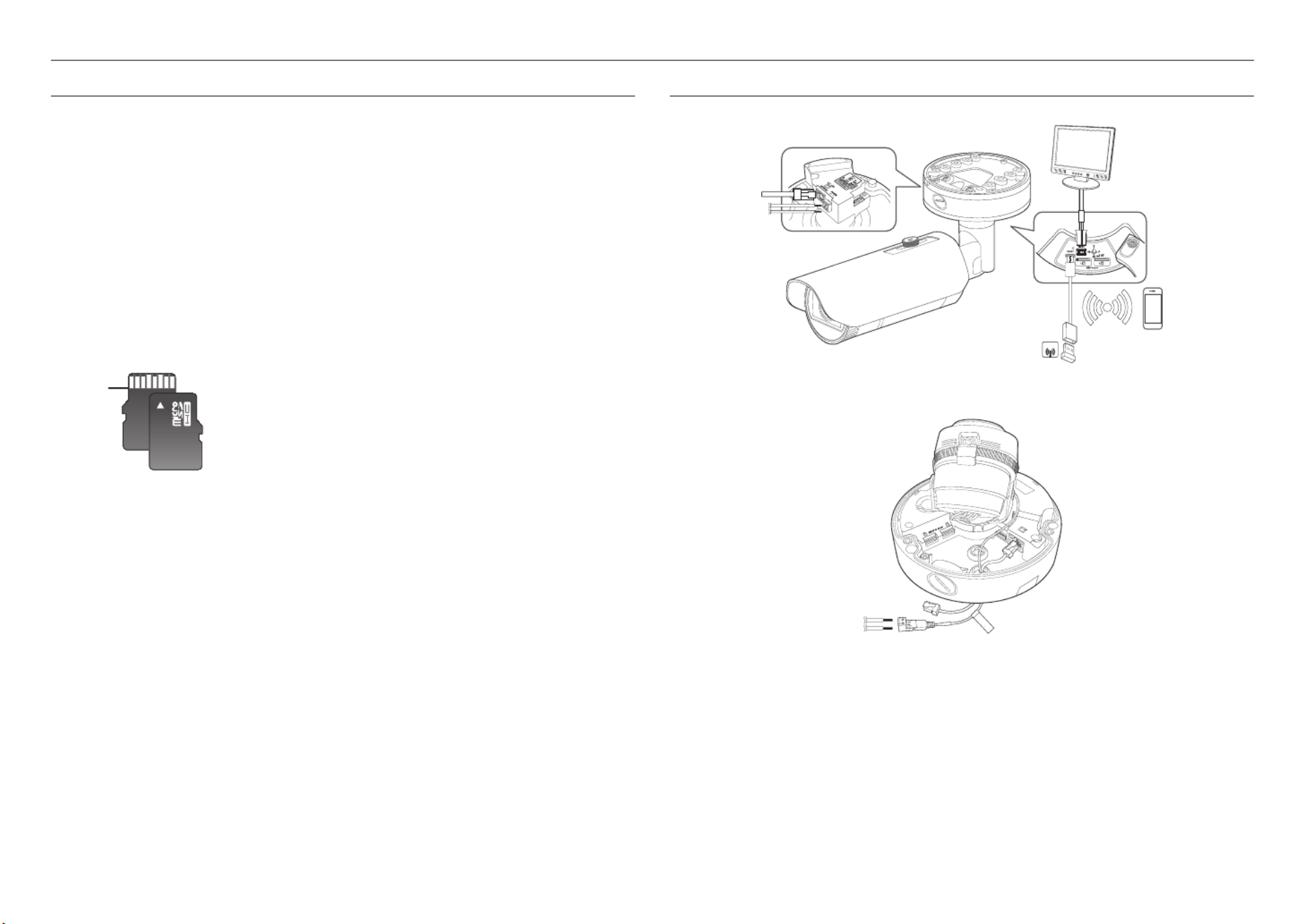
CONNECTING WITH OTHER DEVICE
J
`The CVBS out terminal of the product is provided for easier installation, and is not recommended for monitoring purposes.
`The Micro USB out terminal of the product is provided for easier installation, and is not recommended for monitoring
purposes.
MEMORY CARD INFORMATION (NOT INCLUDED)
What is a memory card?
The memory card is an external data storage device that has been developed to offer an entirely new way to
record and share video, audio, and text data using digital devices.
Selecting a memory card that’s suitable for you
Your camera supports Micro SD/SDHC/SDXC memory cards.
You may, however, experience compatibility issues depending on the model and make of the memory card.
The following types of memory cards from the following manufacturers are recommended for this camera.
- Manufacturer : SanDisk, Transcend
- Product family : High endurance
It is recommended to use a 16GB to 256GB (MLC type) memory card for this camera.
Playback performance can be affected depending on the speed of memory card.
Memory Card Components
Micro SD/SDHC/SDXC
Contacts
SOFT
AP
Monitor to install
Ethernet
Power
Wi-Fi dongle
<XNO-6120R>
CAUTION : Be ware o f the
Rated Vo lta ge a nd P olari ty
of the power conne ction .
AU DI O
ALA R M
NETWO RK
LIN K
ACT
21
Ethernet
Power
<XNV-6120/XNV-6120R>
English _19
●●INSTALLATION & CONNECTION
Ethernet Connection
Connect the Ethernet cable to the local network or to the Internet.
Connecting Wi-Fi
Camera Setup
1. Connect OTG adapter (5-pin) and WiFi dongle to the micro USB terminal.
Smartphone Setup
1. Install the Wisenet Installation application.
2. Select the camera SSID after turning on the WiFi.
3. Run the Wisenet Installation application.
4. When you log in to the camera, the video will be connected. (initial password: 4321)
`The video will be played without being logged in during the initial connection.
5. The camera angle can be adjusted through the smartphone video.
Recommended dongle manufacturer
Manufacturer Model
NETIS WF2123 n300
EDIMAX EW-7811Un
IP Time N100mini
TP-LINK TL-WN823N V1
ASUS USB-N13
NETGEAR WNA3100M
Power Supply
Use the screwdriver to connect each line (+, –) of the power cable to the corresponding power port of the
camera.
J
`When supplying PoE and DC 12V or PoE and AC 24V power at the same time, the equipment is powered by the external
source (AC 24V, DC 12V).
-You can also use a router featuring PoE to supply power to the camera.
-Use PoE that is compliant with the IEEE 802.3af protocols.
-It is recommended to use a single source for powering the equipment among PoE, DC 12V and AC 24V.
`Be careful not to reverse the polarity when you connect the power cable.
`AC 24V can be connected in non-polar union.
`If you want to connect an external device, you must turn off the external device before proceeding.
`Connect the set and the adapter power line first, and then connect the power cable to the outlet on the wall.
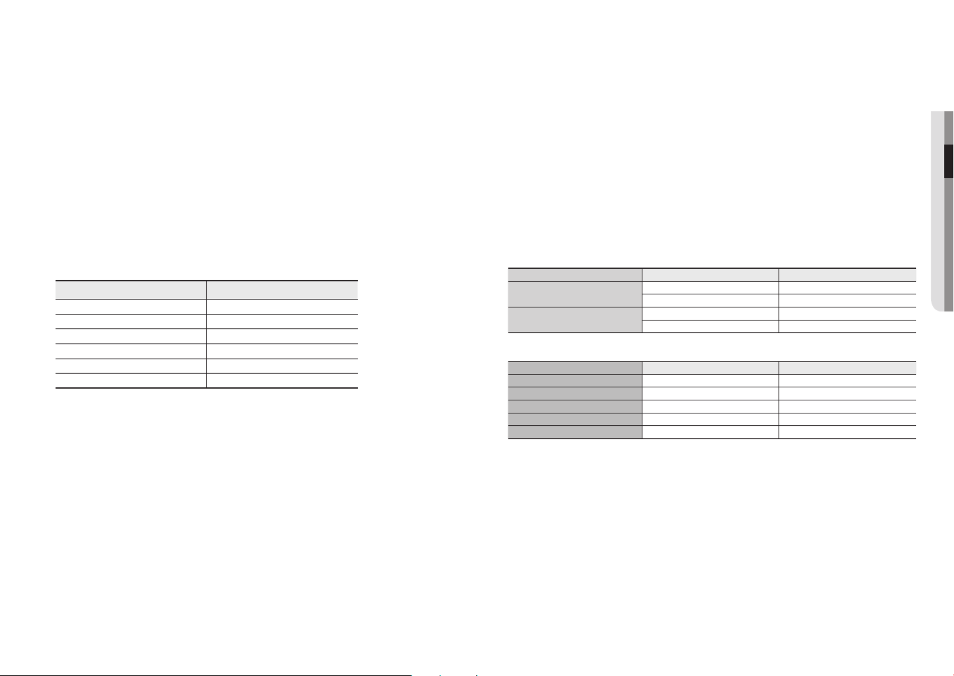
Power Cable Specification for Each Model
Input power Wire Type (AWG) Cable Length (Max.)
DC 12V #18 19m
#16 30m
AC 24V #20 26m
#18 40m
Network Cable Specification
Item Contents Remark
Connector RJ45
Ethernet 10/100BASE-T 10/100 Mbps
Cable UTP Category 5e
Max Distance 100M
PoE Support IEEE 802.3af
installation & connection
20_ installation & connection
Connecting to Audio Input/Output
1. Connect the AUDIO IN port of the camera with the microphone or LINE OUT port of the amplifier that the
microphone is connected to.
2. Connect the AUDIO OUT port of the camera with the speaker or LINE IN port of the amplifier that the
speaker is connected to.
3. Check the specifications for audio input.
•Audio Codec
- Audio In : G.711 PCM (Bit Rate: 64kbps / Sampling Frequency: 8kHz), G.726 ADPCM (Bit Rate:
16Kbps, 24Kbps, 32Kbps, 40Kbps / Sampling Frequency: 8kHz), AAC (Bit Rate: 48Kbps / Sampling
Frequency: 16kHz)
- Audio Out : G.711 PCM (Bit Rate: 64kbps / Sampling Frequency: 8kHz)
•Full duplex Audio
•Audio in : Selectable (microphone/Line-in), Supported voltage: 2.5VDC (4mA), Input impedance: 2K Ohm
•Audio out : Line-out (3.5mm mono jack), Maximum output: 1Vms
•Line out impedance : 600Ω
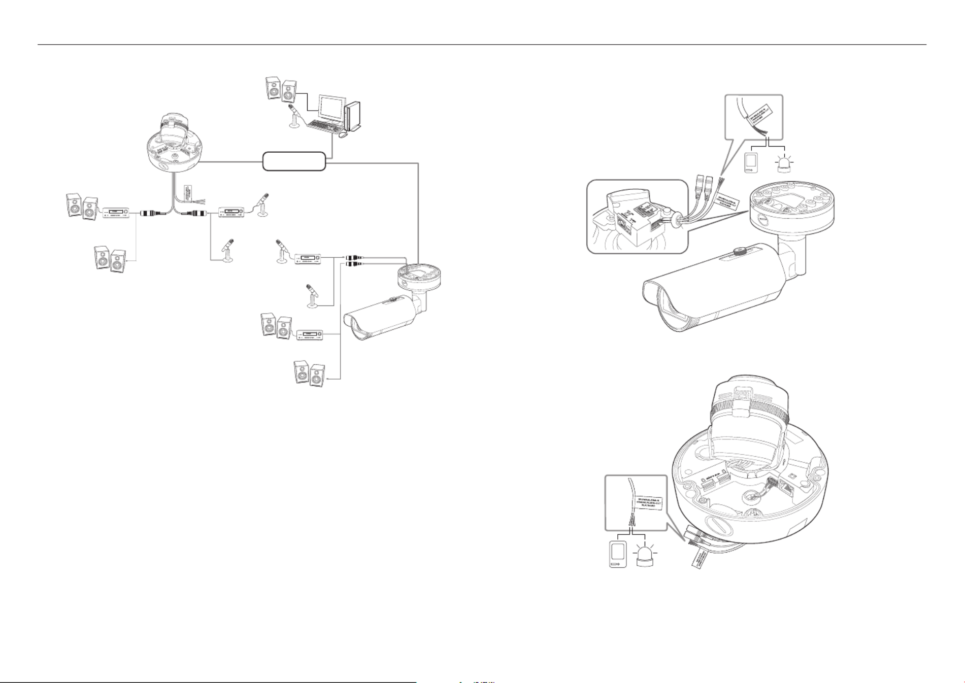
Connecting to the I/O port box
Connect the Alarm I/O cable to the corresponding port of the port box.
AUDIO
ALARM
NETWORK
LINK
ACT
2
1
Network
Microphone
Microphone
Microphone
Microphone
Microphone
AmpAmp
Amp
Amp
Speaker
Speaker
Speaker
Speaker
Speaker
Sensor
Alarm (Warning lamp)
<XNO-6120R>
<XNV-6120/XNV-6120R>
AUDIO
ALA RM
NETWORK
LINK
ACT
2
1
Sensor
Alarm (Warning lamp)

English _21
●●INSTALLATION & CONNECTION
•ALARM-IN : Used to connect the alarm input sensor or external day/night sensor.
•ALARM-OUT : Used to connect the alarm output signal.
•GND : Common port for alarm in/output signal.
J
`If devices (e.g., flashing light and siren) that exceed the voltage and current specifications are connected by using the open
collector method, it may cause malfunction.
Refer to the “ ” when connecting devices that exceed the voltage and current specifications. (page Alarm Out Wiring Diagram 21)
To connect the external sensor
Connect one strand of each signal line (2-strand) of the sensors to the [ ] port, and connect the ALARM IN
other strand to the [ ] port.GND
Alarm In Wiring Diagram
To connect the alarm out
If devices (e.g., flashing light and siren) that exceed the voltage and current specifications are connected by
using the open collector method, it may cause malfunction.
Refer to the alarm out connection diagram below when connecting devices that exceed the voltage and
current specifications.
Alarm Out Wiring Diagram
Sensor
GND
RESISTORALARM IN (5mA SINK)
RESISTOR RESISTOR
VCC_3.3V
DIODE
GND
MLCC TRANSISTOR
External
connection
Inside of the camera
Warning lamp /
Siren power
Warning lamp /
Siren
(
-
) (
+
)
ALARM OUT (12VDC 20mA MAX)
RESISTOR 10K ohm
DIODE
RELAY
DC 5V or 3.3V
TRANSISTOR
GND
GND
TRANSISTOR
External connection Inside of the camera
GND
RESISTOR
22_ network connection and setup
network connection and setup
You can set up the network settings according to your network configurations.
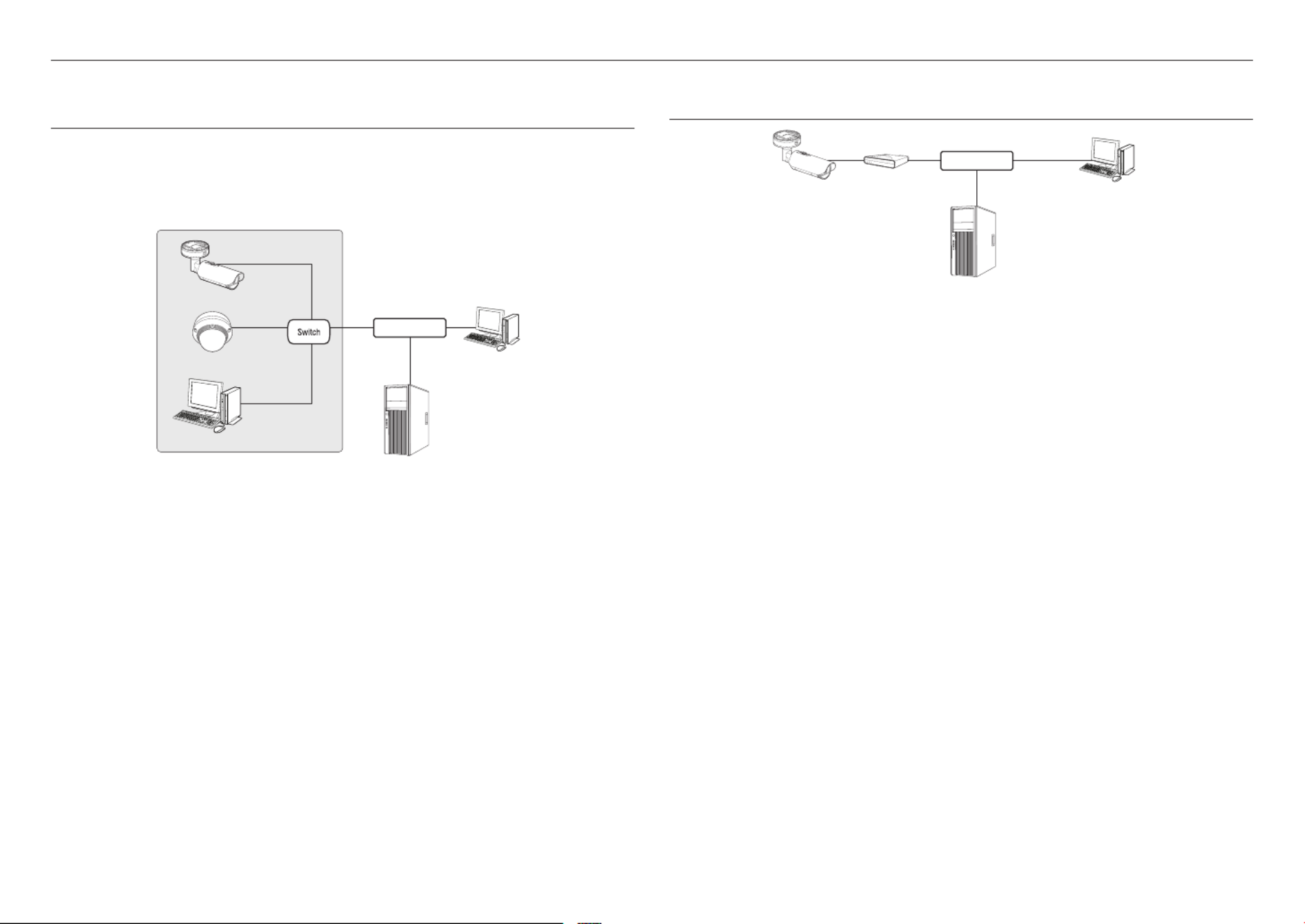
CONNECTING THE CAMERA DIRECTLY TO LOCAL AREA NETWORKING
Connecting to the camera from a local PC in the LAN
1. Launch an Internet browser on the local PC.
2. Enter the IP address of the camera in the address bar of the browser.
M
`A remote PC in an external Internet out of the LAN network may not be able to connect to the camera installed in the intranet
if the port-forwarding is not properly set or a firewall is set.
In this case, to resolve the problem, contact your network administrator.
`In the IP installer, you can use the initial password, “ ” to set IP Address, Subnet Mask, Gateway, HTTP Port, VNP Port, IP 4321
type. After changing the network interface, for better security, access the web viewer and change the password.
`By factory default, the IP address will be assigned from the DHCP server automatically.
If there is no DHCP server available, the IP address will be set to 192.168.1.100.
To change the IP address, use the IP Installer.
For further details on IP Installer use, refer to “ ”. (Page Static IP Setup 24)
CONNECTING THE CAMERA DIRECTLY TO A DHCP BASED DSL/CABLE
MODEM
1. Connect the user PC directly with the network camera.
2. Run the IP Installer and change the IP address of the camera so that you can use the web browser on
your desktop to connect to the Internet.
3. Use the Internet browser to connect to the web viewer.
4. SetupMove to [ ] page.
5. Network DDNSMove to [ ] – [ ] and configure the DDNS settings.
6. Basic IP & Port DHCPMove to [ ] – [ ], and set the IP type to [ ].
7. Connect the camera, which was removed from your PC, directly to the modem.
8. Restart the camera.
M
`For configuring the DDNS settings, refer to “ ”. (page DDNS 46)
`For registering the DDNS settings, refer to “ ”. (page Registering with DDNS 46)
`Refer to “IP & Port” for how to setup IP. (page 38)
<Local Network>
Camera
Camera
Local PC
INTERNET
External Remote PC
DDNS Server
(Data Center, KOREA)
Camera External Remote PC
DDNS Server
(Data Center, KOREA)
DSL/Cable Modem
INTERNET
English _23
●●NETWORK CONNECTION AND SETUP
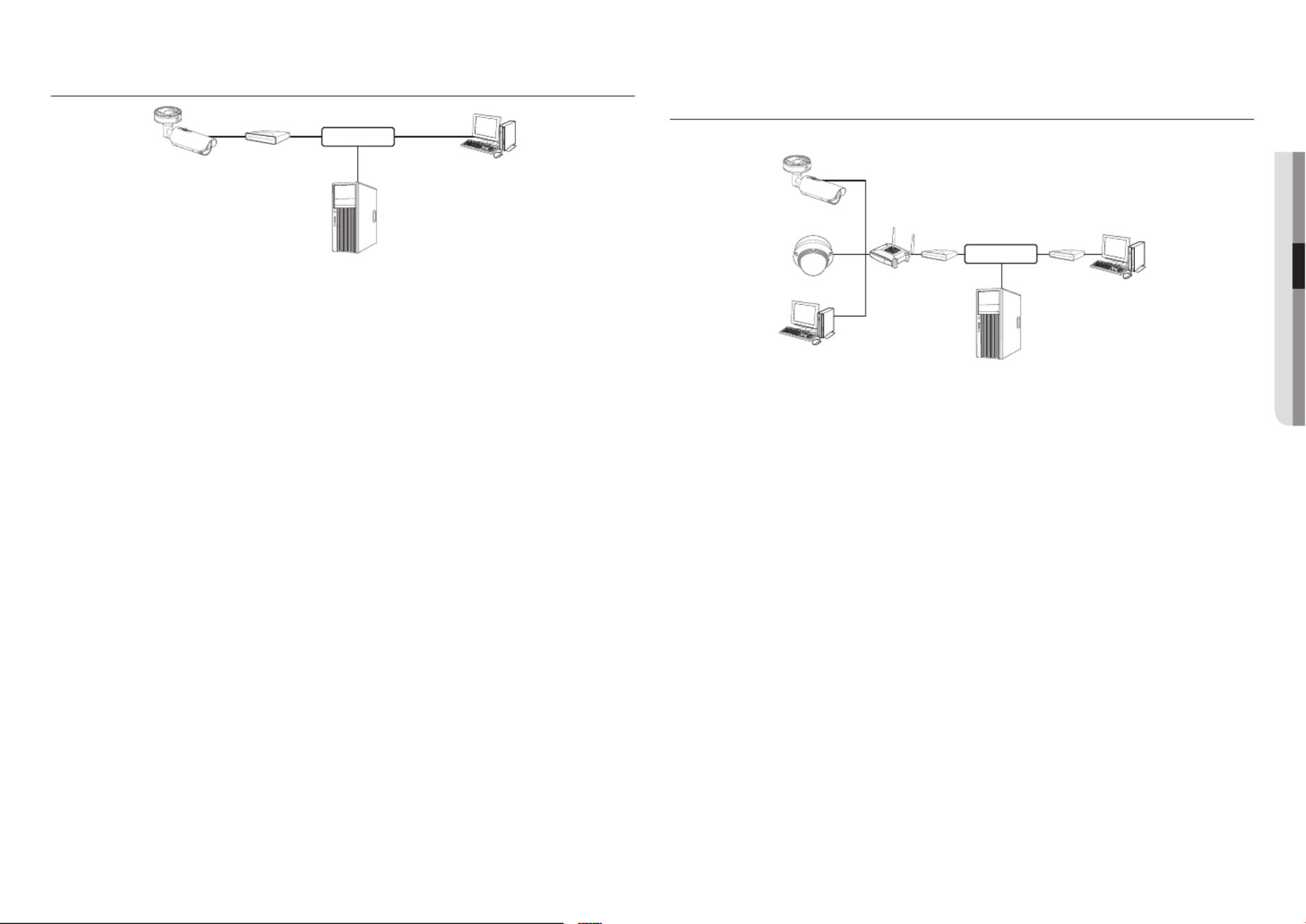
CONNECTING THE CAMERA DIRECTLY TO A PPPoE MODEM
1. Connect the user PC directly with the network camera.
2. Run the IP Installer and change the IP address of the camera so that you can use the web browser on
your desktop to connect to the Internet.
3. Use the Internet browser to connect to the web viewer.
4. SetupMove to [ ] page.
5. Network DDNSMove to [ ] – [ ] and configure the DDNS settings.
6. Basic IP & Port PPPoEMove to [ ] – [ ] Setup Page, set the IP type to [ ], and enter the network service’s ID
and password.
7. Connect the camera, which was removed from your PC, directly to the modem.
8. Restart the camera.
M
`For configuring the DDNS settings, refer to “ ”. (page DDNS 46)
`For registering the DDNS settings, refer to “ ”. (page Registering with DDNS 46)
`Refer to “IP & Port” for how to setup IP. (page 38)
CONNECTING THE CAMERA TO A BROADBAND ROUTER WITH THE
PPPoE/CABLE MODEM
This is for a small network environment such as homes, SOHO and ordinary shops.
Configuring the network settings of the local PC connected to a Broadband Router
Configuring the network settings of the local PC connected to a Broadband Router, follow the instructions
below.
•Select : < > Network < > Properties < > Local Area Connection < > General < > Properties
< > Internet Protocol (TCP/IP) < > Properties < > or <Obtain an IP address automatically Use the
following IP address>.
•Follow the instructions below if you select < >:Use the following IP address
ex1) If the address (LAN IP) of the Broadband Router is 192.168.1.1
IP address : 192.168.1.100
Subnet Mask : 255.255.255.0
Default Gateway : 192.168.1.1
ex2) If the address (LAN IP) of the Broadband Router is 192.168.0.1
IP address : 192.168.0.100
Subnet Mask : 255.255.255.0
Default Gateway : 192.168.0.1
ex3) If the address (LAN IP) of the Broadband Router is 192.168.xxx.1
IP address : 192.168.xxx.100
Subnet Mask : 255.255.255.0
Default Gateway : 192.168.xxx.1
M
`For the address of the Broadband Router, refer to the product’s documentation.
`For more information about port forwarding of the broadband router, refer to “Port Range Forward (Port Mapping) Setup”.
(Page 26)
Camera
Camera
Local PC
Broadband
Router
PPPoE or
Cable Modem
PPPoE or
Cable Modem External Remote PC
DDNS Server
(Data Center, KOREA)
INTERNET
Camera External Remote PC
DDNS Server
(Data Center, KOREA)
PPPoE Modem
INTERNET

network connection and setup
24_ network connection and setup
BUTTONS USED IN IP INSTALLER
Item Description
a
Device Name
Model name of the connected camera.
Click the column to sort the list by model name.
However, search will be stopped if clicked during the search.
b
Alias This function is not currently implemented.
c
Mode Displays either < > or < > for the current network connection Static>, <Dynamic PPPoE
status.
d
MAC(Ethernet) Address
Ethernet address for the connected camera.
Click the column to sort the list by Ethernet address.
However, search will be stopped if clicked during the search.
e
IP Address
IP address.
Click the column to sort the list by IP address.
However, search will be stopped if clicked during the search.
f
Protocol
Network setting for the camera.
The factory default is “IPv4”.
Cameras with the IPv6 setting will be displayed “IPv6”.
g
URL
DDNS URL address enabling access from the external Internet.
However, this will be replaced with the < > of the camera if DDNS registration IP Address
has failed.
h
IPv4 Scans for cameras with the IPv4 setting.
a b c d e f g
h i j k l m
Item Description
i
IPv6 Scans for cameras with the IPv6 setting.
Activated in an IPv6 compliant environment only.
j
Search Scans for cameras that are currently connected to the network.
However, this button will be grayed out if neither IPv4 nor IPv6 is checked.
k
Auto Set The IP Installer automatically configures the network settings.
l
Manual Set You should configure the network settings manually.
m
Exit Exits the IP Installer program.
M
`
For the IP installer, use only the installer version provided in the installation CD or use the latest one if available. You can download
the latest version from the Hanwha Techwin web site.
`If the supporting OS is Windows 8.1, it is recommended that you use the Wisenet Device Manager instead of the IP Wisenet.
The Wisenet Device Manager Program can be downloaded by visiting the Hanwha Techwin website (http://www.hanwha-
security.com) under the menu < > - <Customer Support Technical Guides> - <Online Tool>.
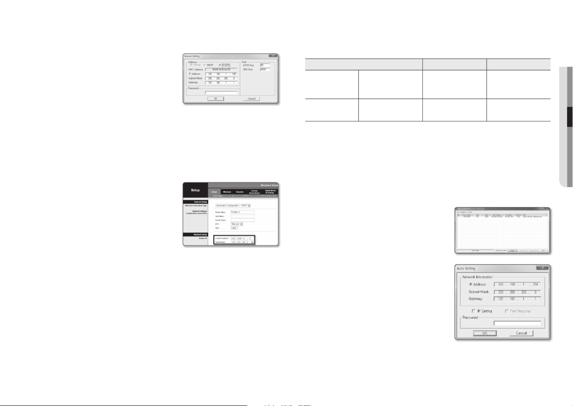
STATIC IP SETUP
Manual Network Setup
Run < > to display the camera search list. IP Installer_v2.XX.exe
At the initial startup, both [ ] and [ ] will be grayed out.Auto Set Manual Set
M
`For cameras found with the IPv6 setting, these buttons will be grayed out as the cameras do not support this function.
1. Select a camera in the search list.
Check the MAC address of the camera on the camera’s label.
Both the [ ] and [ ] buttons will be Auto Set Manual Set
activated.
2. Manual SetClick [ ].
The Manual Setting dialog appears.
< >, < >, < >, <IP Address Subnet Mask Gateway HTTP
Port VNP Port>, and < > of the camera are displayed in the
preset values.
3. AddressIn the < > pane, provide the necessary information.
•MAC (Ethernet) Address : The MAC address imprinted on
the camera label is automatically displayed and requires no
user setting.
M
`IP related parameters can be set only when DHCP is not checked.
English _25
●●NETWORK CONNECTION AND SETUP
If not using a Broadband Router
For setting < >, < >, and < >, contact your network administrator.IP Address Subnet Mask Gateway
4. PortIn the < > pane, provide necessary information.
•HTTP Port : Used to access the camera using the Internet
browser, defaulted to 80.
•VNP Port : Used to control the video signal transfer,
defaulted to 4520.
5. Enter the password.
Enter the password of “ ” account, which was used to admin
access the camera.
J
`For the security purposes, you are recommended to use a combination of numbers, alphabets uppercase and lowercase and
special characters for your password.
`If you want to change the password, refer to “ ” of the user setup. (page Administrator password change 37)
6. OKClick [ ].
Manual network setup will be completed.
If using a Broadband Router
•IP Address : Enter an address falling in the IP range provided
by the Broadband Router.
ex) 192.168.1.2~254, 192.168.0.2~254,
192.168.XXX.2~254
•Subnet Mask : The < > of the Broadband Router Subnet Mask
will be the < > of the camera.Subnet Mask
•Gateway : The < > of the Broadband Router Local IP Address
will be the < > of the camera.Gateway
M
`The settings may differ depending on the connected Broadband
Router model.
For more information, refer to the user manual of the applicable router.
`For more information about port forwarding of the broadband router, refer to “Port Range Forward (Port Mapping) Setup”.
(Page 26)
If the Broadband Router has more than one camera connected
Configure the IP related settings and the Port related settings distinctly with each other.
ex)
Category Camera #1 Camera #2
IP related settings
IP Address
Subnet Mask
Gateway
192.168.1.100
255.255.255.0
192.168.1.1
192.168.1.101
255.255.255.0
192.168.1.1
Port related settings HTTP Port
VNP Port
8080
4520
8081
4521
M
`If the < > is set other than 80, you must provide the < > number in the address bar of the Internet browser HTTP Port Port
before you can access the camera.
ex) http://IP address : HTTP Port
http://192.168.1.100:8080
Auto Network Setup
Run < > to display the camera search list. IP Installer_v2.XX.exe
At the initial startup, both [ ] and [ ] will be grayed out.Auto Set Manual Set
M
`For cameras found with the IPv6 setting, these buttons will be grayed out as the cameras do not support this function.
1. Select a camera in the search list.
Check the MAC address of the camera on the camera’s label.
Both the [ ] and [ ] buttons will be Auto Set Manual Set
activated.
2. Auto SetClick [ ].
The Auto Setting dialog appears.
The < >, < >, and < > will IP Address Subnet Mask Gateway
be set automatically.
3. Enter the password.
Enter the password of “ ” account, which was used to admin
access the camera.
J
`For the security purposes, you are recommended to use a
combination of numbers, alphabets uppercase and lowercase and
special characters for your password.
`If you want to change the password, refer to “Administrator
password change” of the user setup. (page 37)
4. OKClick [ ].
Auto network setup will be completed.

network connection and setup
26_ network connection and setup
DYNAMIC IP SETUP
Dynamic IP Environment Setup
• Example of the Dynamic IP environment
- If a Broadband Router, with cameras connected, is assigned an IP address by the DHCP server
- If connecting the camera directly to modem using the DHCP protocols
- If IPs are assigned by the internal DHCP server via the LAN
Checking the Dynamic IP
1. Run the IP Installer on the user’s local computer.
Cameras allocated with < > address are shown in Dynamic IP
the list.
2. Select a camera from the search result.
3. Manual SetClick the [ ] button and check the camera’s
< > address. Dynamic IP
If you uncheck < >, you can change IP to < >.DHCP Static
PORT RANGE FORWARD (PORT MAPPING) SETUP
If you have installed a Broadband Router with a camera connected, you must set the port range forwarding on the
Broadband Router so that a remote PC can access the camera in it.
Manual Port Range Forwarding
1. From the Setup menu of the Broadband Router, select
< > - < >. Applications & Gaming Port Range Forward
For setting the port range forward for a third-party Broadband
Router, refer to the user guide of that Broadband Router.
2. TCP UDP PortSelect < > and < > for each connected camera
to the Broadband Router.
The number of each port to be configured to the IP router
should be set according to the port number designated
in < > - < > - < > on the camera web Setup Basic IP & Port
viewer.
3. Save SettingsWhen done, click [ ].
Your settings will be saved.
M
`Above sample instructions are based on the CISCO’s Broadband Router.
`The settings may differ depending on the connected Broadband Router model.
For more information, refer to the user manual of the applicable router.
Setting up Port Range Forward for several network cameras
• You can set a rule of Port Forwarding on the Broadband Router device through its configuration web page.
• A user can change each port using the camera setting screen.
When Camera1 and Camera2 are connected to a router :
M
`Port forwarding can be done without additional router setup if the router supports the UPnP (Universal Plug and Play) fun
After connecting the network camera, select the checkbox from the menu < > in < > in Quick connect Wisenet DDNS
“Settings -> -> Network DDNS”.
User Internet
Broadband Router
Start End Protocol IP Address
3000 3000 TCP/UDP 192.168.1.100
3001 3001 TCP/UDP 192.168.1.101
4520 4520 TCP/UDP 192.168.1.100
4521 4521 TCP/UDP 192.168.1.101
8080 8080 TCP/UDP 192.168.1.100
8081 8081 TCP/UDP 192.168.1.101
Camera1 (192.168.1.100)
HTTP port 8080
Device port 4520
RTSP port 3000
Camera2 (192.168.1.101)
HTTP port 8081
Device port 4521
RTSP port 3001

English _27
●● networK connection anD Setup
connectinG to tHe camera from a SHareD LocaL pc
1. Run the IP Installer.
It will scan for connected cameras and display them as a list.
2. Double-click a camera to access.
The Internet browser starts and connects to the camera.
M
`Access to the camera can also be gained by typing the camera’s IP
address in the address bar of the Internet browser.
connectinG to tHe camera from a remote pc via tHe
internet
Since using the IP Installer on a remote computer that is not in the Broadband Router’s network cluster is not
allowed, users can access cameras within a Broadband Router’s network by using the camera’s DDNS URL.
1. Before you can access a camera in the Broadband Router network, you should have set the port range
forward for the Broadband Router.
2. From the remote PC, launch the Internet browser and type the DDNS URL address of the camera, or the
IP address of the Broadband Router in the address bar.
ex) http://ddns.hanwha-security.com/ID
M
`For registering the DDNS settings, refer to “ ”. (page Registering with DDNS 46)

28_ web viewer
web viewer
CONNECTING TO THE CAMERA
Normally, you would
1. Launch the Internet browser.
2. Type the IP address of the camera in the address bar.
ex) • IP address (IPv4) : 192.168.1.100
http://192.168.1.100
- the Login dialog should appear.
• IP address (IPv6) : 2001:230:abcd: ffff:0000:0000:ffff:1111
http://[2001:230:abcd:ffff:0000:0000:ffff:1111] - the Login
dialog should appear.
If the HTTP port is other than 80
1. Launch the Internet browser.
2. Type the IP address and HTTP port number of the camera in the address bar.
ex) IP address : 192.168.1.100:HTTP Port number(8080)
http://192.168.1.100:8080 - the Login dialog should appear.
Using URL
1. Launch the Internet browser.
2. Type the DDNS URL of the camera in the address bar.
ex) URL address : http://ddns.hanwha-security.com/ID
- the Login dialog should appear.
J
`Network connection is disabled in the LAN only environment.
Connecting via UPnP
1. Run the client or operating system in support of the UPnP protocol.
2. Click the camera name for search.
In the Windows operating system, click the camera name searched from the network menu.
- The login window is displayed.
Connecting via Bonjour
1. Run the client or operating system in support of the Bonjour protocol.
2. Click the camera name for search.
In the Mac operating system, click the camera name searched from the Bonjour tab of Safari.
- The login window is displayed.
To check the DDNS address
If the camera is connected directly to the DHCP cable modem, DSL modem, or PPPoE modem, the IP
address of your network will be changed each time you try to connect to the ISP (Internet Service Provider)
server.
If this is the case, you will not be informed of the IP address changed by DDNS.
Once you register a dynamic IP-based device with the DDNS server, you can easily check the changed IP
when you try to access the device.
To register your device to the < > server, visit http://ddns.hanwha-security.com and register your device DDNS
first, and then set the Web Viewer’s < > - < > to < >, as well as providing Network DDNS Wisenet DDNS
< > that had been used for DDNS registration.Product ID

English _29
●● WEB VIEWER
PASSWORD SETTING
When you access the product for the first time, you must register the
login password.
When the “ ” window appears, enter the new Password change
password.
J
`For a new password with 8 to 9 digits, you must use at least 3 of
the following: uppercase/lowercase letters, numbers and special
characters. For a password with 10 to 15 digits, you must use at
least 2 types of those mentioned.
- Special characters that are allowed. : ~`!@#$%^*()_-+=|{}[].?/
`For higher security, you are not recommended to repeat the same characters or consecutive keyboard inputs for your
passwords.
`If you lost your password, you can press the [ ] button to initialize the product. So, don’t lose your password by using a RESET
memo pad or memorizing it.
LOGIN
Whenever you access the camera, the login window appears.
Enter the User ID and password to access the camera.
1. admin User nameEnter “ ” in the < > input box.
The administrator ID, “ ”, is fixed and can not be admin
changed.
2. PasswordEnter the password in the < > input field.
3. OKClick [ ].
If you have logged in successfully, you will the Live Viewer
screen.
J
`When you access the camera web viewer, pay special attention to the
security by checking whether the image data is encrypted.
M
`If you check the “ ” option when your input is done, in future you will be logged in automatically Remember my credentials
without being prompted to enter the login information.
`You will experience the best video quality if the screen size is 100%. Reducing the ratio may cut the image on the borders.
PLUG-IN SUPPORT SPECIFICATIONS FOR EACH BROWSER
The existing plug-in web viewer and a new plug-in free web view is embedded together.
This allows you to use the web viewer in newer browser environments that do not support plug-ins, such as
Chrome, EDGE, FireFox (Windows 64-bit only), and Safari. For browsers that allow the installation of plug-ins,
such as IE and Safari, installing the plug-in is recommended.
According to the browser environment, the following differences may be observed.
• Chrome, FireFox(Windows 64bit only), EDGE browser : Although they don’t support plug-ins, you can
use a web viewer as a plug-in free web viewer is embedded.
J
`As the plug-in free webviewer has lower performance than the plug-in webviewer, it has a limit on the monitoring of high
quality profiles and playback of saved videos.
To monitor high quality profiles and play saved videos, use either a plug-in webviewer or SmartViewer.
- Plugin-free webviewer creation conditions: The selected profile exceeds MJPEG Full HD 10fps H.264 (Chrome : full scre
resolution supported / Edge, Firefox, Safari : Full HD 30 fps or higher) H.265 FullHD 10fps 2Mbps or higher
- Plugin-free playback conditions: MJPEG/H.264 full screen resolution, H.265 HD or below
`The plug-in free feature has been optimized for the Chrome browser.
`Supports Adaptive Streaming
- This is the feature that automatically lowers the profile if there is a delay of more than 5 seconds. It was made to prevent
issues such as increased latency and no response from the browser when playing the video on a system with lower hardwa
specifications than recommended.
The video profile is reduced in the following sequence: 1920X1080(20fps) -> 1280X720(20fps) -> 640X480(20fps).
`In the following cases, the detection performance may be impaired or an malfunction may occur.
- Monotonous monitoring environment, night or low illumination environment
- Severe camera wobbling and sudden changes in illumination
• IE, Safari browser : You can use a web viewer even if you don’t install the existing plug-in web viewer.
J
`To monitor/play saved video seamlessly, you are required to install a plug-in.
`In the following cases, the detection performance may be impaired or an malfunction may occur.
- Monotonous monitoring environment, night or low illumination environment
- Severe camera wobbling and sudden changes in illumination

web viewer
30_ web viewer
INSTALLING WebViewer PLUGIN
To access to the plug-in webviewer and play a live video (H.264/H.265) or a recorded video, an installation
message will be prompted. At this time you need to install the webviewer plug-in to use the function properly.
1. When the monitoring page is accessed for the very first time, the installation page is displayed. Click
[ ] to begin installation.Download plugin
J
`If the plug-in installation file download status is suspended at 99% in the Internet Explorer browser, retry it after selecting
“Release SmartScreen filter” in “Tool
SmartScreen filter”.
2. RunClick [ ] in the message window.
3. YesClick [ ] when the notice window saying that all browser windows will be closed.
M
`Steps 4 and 5 will be skipped if no Web Viewer Plug-in is installed.
4. When the old version of the Web Viewer Plug-in is installed, a notice window saying the old version will be
deleted is displayed.
Click [Yes] when the notice window is displayed.
5. OKClick [ ].
The old version of Web Viewer Plug-in is deleted.
6. InstallClick [ ] to begin installation of the Web Viewer Plug-in.
7. FinishClick [ ].
Web Viewer Plug-in installation is completed.
J
`In your internet explorer, if you need to move to the installation screen after installing the webviewer plugin, check whether
webviewer_activexplugin_lib.control in the “Tool
Additional Function Management” menu is “Activated”. If not, and if there
is a persisting problem, then select “Tools
Internet Options
General” and delete all the search records.
If the problem persists, please register the IP or Domain of your camera in “Tools
Internet Options
Security
Trusted
sites”.
USING A PLUG-IN FREE WEBVIEWER
Although it is not possible to install plug-ins separately If you access the camera from Google Chrome, Mozilla
Firefox, or the MS Edge web browser, you can view and control the camera video without installing plug-ins.
1. Enter your username and password to log in.
2. When you are logged in, a camera live view screen appears.
USING THE LIVE SCREEN
Item Description
a
Live Moves to the Live screen.
b
Playback Move to the screen where you can search for the video recording saved in your Micro SD memory
card or NAS.
c
Setup Move to the Setup screen.
d
Viewer Screen Displays the Live video on the screen.
`You can use the mouse wheel to activate the digital zooming in Viewer screen.
e
Webviewer plug-in
installation You can install webviewer plug-ins to play live or recorded videos (only available in IE and Safar
f
Online help The Online help provides detailed descriptions for each function.
g h i j k l m n o p
a b c d e f

English _31
●● WEB VIEWER
Item Description
o
Alarm output Activate the Alarm Out port.
p
Audio control Activates audio and adjusts the volume.
J
`Some functions may not work on a specific browser or codec.
To capture the snapshot
1. Capture ( )Click [ ] on the scene to capture.
2. When a captured video is saved, a notification message appears.
The captured image is saved in the designated folder for each browser.
M
`If the screen is not captured by IE browser in Windows 7 or higher, run the IE Browser with the Admin privilege.
To save
1. Record ( )Click the [ ] icon.
2. To end the recording, press [Record ( )] again.
M
`You can save the recorded file on the PC in an avi file format. Designate a path and save the video.
To fit the full screen
1. Full Screen ( )Click the [ ] icon.
2. This will fit the Viewer to the full screen.
3. To leave full screen mode, click the [Full Screen ( ) Esc] button again or press the [ ] key on the
keyboard.
To Use Audio
1. Audio ( )Click [ ] icon to activate audio communication.
2. Use [ ] bar to control the volume.
M
`If there is no sound from pulling in and out the audio jack while it is in operation, click the [ ] icon to enable Audio ( )
again.
`To use audio, you need to set < ” to < > (page Audio in> in “Video Profile Enable 35).
Item Description
g
Profile type
You can select a profile type in < > under the < > setup menu.Video profile Basic
`Click the icon to display the name of the current profile.
J
`
Afterimages can be displayed on the screen under the following conditions if the video is
played in the monitoring page:
- The resolution is changed due to a profile change.
- Incoming data is being slowed due to a network delay when the profile is changed.
- The web browser window size and location is changed.
h
Zoom/Focus
It controls the zoom/focus functions of the camera.
Zoom In ( )
Move the bar at the right side of the UI to the right, or push the [ ]
button to enlarge the magnification of the screen.
The farther the bar position is from the center, the faster the screen
will be zoomed in.
Zoom Out ( )
Move the bar in the right side of the UI to the left, or push the [ ]
button to reduce the magnification of the screen.
The farther the bar position is from the center, the faster the screen
will be zoomed out.
Close-range focus ( ) It focuses on objects at close range.
Long-range focus ( ) It focuses on objects at long range.
Auto focus ( ) It automatically adjusts the focus of the screen.
i
Profile access information You can read the profile information.
j
Switch View Mode
Full Screen ( ) Double click on the video screen, and the current video will be
played in the full screen of the monitor.
Fit to screen ( ) A view mode in which the size of the camera video automatically fits
to the web browser size.
Size of the original file
( ) View mode in which the video is played in the actual resolution.
Maintain Aspect Ratio
( ) View mode that adjusts the aspect ratio to best fit the resolution.
k
Capture Saves the snapshot as an image file in the .png format.
l
Record The user can save the video on the PC.
m
Pixel Counter Checks the number of pixels in the selected area on the video screen.
n
Microphone control Activates the microphone.
web viewer
32_ web viewer
To Use Microphone
Click [ ] icon to activate the microphone.Mic ( )
M
`If you are using IE or the Safari browser, you will need to install plug-in.
To count the number of pixels
1. Pixel count ( )Click the [ ] icon to activate it.
2. Drag the mouse on the video to select an area.
3. The number of pixels in the selected area is displayed on the screen.
To control zoom/focus
1. PTZ ( )Click the [ ] icon.
2. Move the zoom cursor [ ] on the screen to zoom in/out.
3. Select [ ] on the screen focus to adjust the focal point.
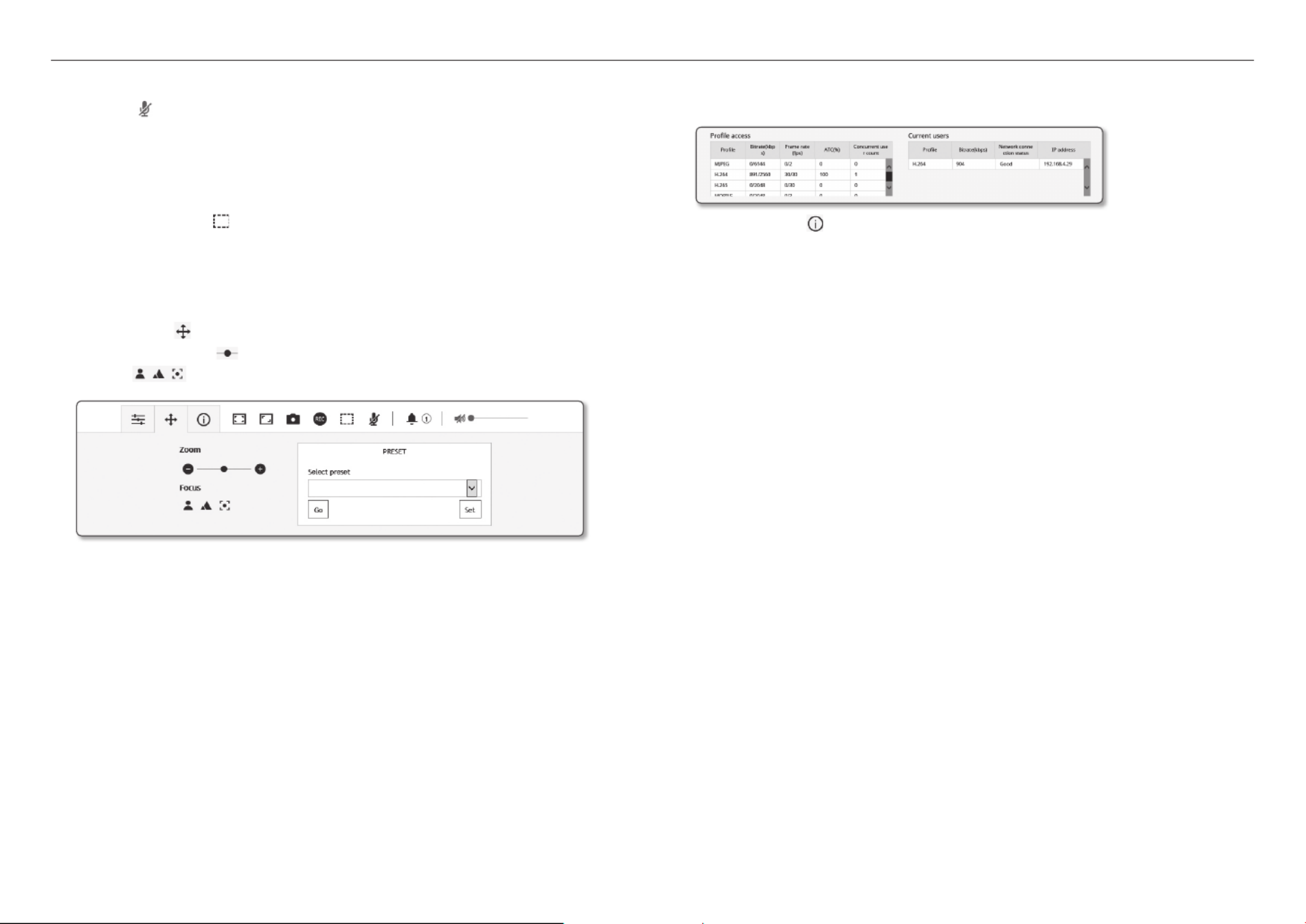
To check the profile status
You can check the profile information.
1. Status ( Click the [ )] icon.
2. The profile access information screen is updated whenever the screen is enabled.
• Profile access : Show the information of the newly added profile.
- Profile : Show the information of the newly added codec.
- Bitrate(kbps) : Show both the actual bit rate and the set bit rate.
- Framerate(fps) : Show both the actual frame rate and the set frame rate.
- ATC(%) : Show the ATC status.
- Concurrent users count : Show the number of concurrent users who access the profile.
• Current users : Shows information on users accessing web viewer and displaying monitoring video.
- Profile : Show the name of the profile accessed by the user.
- Bitrate(kbps) : Show the current bit rate.
- Network connection status : It shows whether the network is working fine.
- IP address : Show the IP address of the current user.

English _33
●● WEB VIEWER
PLAYING THE RECORDED VIDEO
M
`Before you can play the video, you must configure the record settings. For details on record settings, refer to “ ”. (page Storage 50)
Playback Screen Name and Features
Item Description
a
Time Bar Move the time bar to play the video at a desired time.
b
Hide the context menu The contextual menu screen at the bottom will disappear, and only the menu icon will be
displayed.
c
Search event setting Set the event type to search within the search period.
d
Switch View Mode
Full Screen ( ) Double click on the video screen, and the current video will be
played in the full screen of the monitor.
Fit to screen ( ) A view mode in which the size of the camera video automatically fits
to the web browser size.
Size of the original file
( ) View mode in which the video is played in the actual resolution.
Maintain Aspect Ratio
( ) View mode that adjusts the aspect ratio to best fit the resolution.
Item Description
e
Search range setting Set the search date and time range for data saved in your Micro SD memory card or NAS.
f
Capture Saves the current video screen in an image file format (format may vary depending on the
browser).
g
Backup
Set the desired date to make a backup copy of video data saved in your Micro SD memory card
or NAS.
`You can set up to 5 minutes for the backup of a saved video.
h
Audio To listen to a voice signal (if present) in the recorded video, then activate the voice signal icon
when you play it.
i
Viewer Screen The recorded video will appear.
To play the content after searching by event
1. Show ( )On the Playback screen, click the [ ] button.
2. If there is a video recorded on the date of search, the
applicable video is displayed on the time bar.
3. To perform a search by event type, click the [ ] button at All
the top of the time bar and select an event type.
4. ApplyWhen done, click [ ].
Event searched is displayed on the time bar.
5. Play ( Click the [ )] button.
6. To pause the video, click the [Pause ( )] button.
a c g heb fd i

web viewer
34_ web viewer
To play after searching by time
1. Click the [ ] icon.
2. On the calendar, set the search date, start time and end time.
The event searched is displayed on the time bar.
3. Play ( Click the [ )] button.
The video at the selected time will be played.
4. When a video is played, the recording time of the video
currently being played is displayed.
5. Search the video forward and backward and adjust the
playback speed.
- How to Move Playback Interval
When the [ , ] button is selected, it moves forward by 1
frame/moves backward by i frame.
- How to Control Playback Speed
Click the [ ] button and you can select a speed of
either 1x, 2x, 4x and 8x or -1x, -2x, -4x and -8x, and you can set the playback speed as desired.
6. Time Bar ( Move the position of the [ )] to play the video at a desired time.
To back up the searched video
1. BackupDuring playback, click [ ] on the scene to back up.
The data in the applicable section will be backed up.
2. ApplyClick [ ] button.
The Save As window appears.
3. SaveConfirm the save path and click [ ] button.
The screenshot will be backed up to the specified path.
To play the backup video
The backed up images are saved in an .avi format. Installing the media player that supports the format for the
user PC is recommended.
M
`If playback does not run smoothly due to the user environment, optimizing by installing the latest codec and other methods
are required.
To Play an AVI File
(1) Micro SD memory card
1. Separate the Micro SD memory card from the camera.
J
`Before separating the Micro SD memory card, set the < > to < > in the “Device Off Setup
Event
Storage” menu.
2. Insert the Micro SD memory card into the PC.
3. Play the AVI file in the “ RecordingData YYYY_mm_DD
AVI” directory, using a media player.
M
`A filename starts with the format “001_YYYYMMDD_HHMMSS.avi”
and the file number is incremented by one.
YYYYMMDD_HHMMSS indicates the start time of data saving.
`“001_YYYYMMDD_HHMMSS.smi” file is a caption file, and you can
view it if it exists in the same directory as its related AVI file.
`Once corrupted, the data in the Micro SD memory card cannot be
replayed in the Web Viewer’s [Playback].
(2) NAS (Network-Attached Storage)
1. In Windows browser, use \\<ip address>\ to access.
ex) 192.168.13.250 defaultfolder 2017_01_13 AVI
2. ComputerGo to < > < > Network drive connection
Enter 1.
3. Connected to the NAS.
The directory structure is same as the directory structure for a
Micro SD memory card.
M
`A filename starts with the format “001_YYYYMMDD_HHMMSS.avi”
and the file number is incremented by one.
YYYYMMDD_HHMMSS indicates the start time of data saving.
`“001_YYYYMMDD_HHMMSS.smi” file is a caption file, and you can
view it if it exists in the same directory as its related AVI file.
`If you change or damage the saved data on your own, it will not play
back or save properly.
English _35
●● SETUP SCREEN
setup screen
SETUP
You can configure the basic camera information, PTZ, video and audio, network, event, analyze and system
settings.
1. Setup ( On the live screen, click the [ )] button.
2. The Setup screen appears.
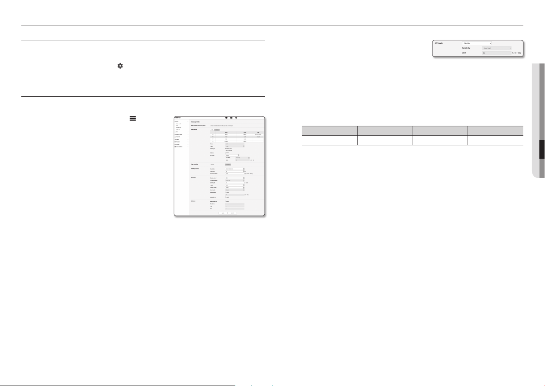
BASIC SETUP
Video profile
1. Basic ( )From the Setup menu, select the < > tab.
2. Video profileClick < >.
3. Video profile connection policySet the < >.
• Keep connection when profile setting is changed : Output
uses the same settings even when the settings of the
active profile are changed.
If not selected, changing a profile used by an existing
connection resets such connection.
4. Select each profile properties.
For more details, refer to “To Add/Change the Video
Profile”. (Page 36)
5. Click the input box of each item and enter / select a desired
value.
`The context menu may differ depending on the selected codec type.
• Default profile : If no profile is selected when using the Web
Viewer, the default video profile is applied.
• E-mail/FTP profile : Video profile to be transferred to the specified email or FTP site.
`Only the MJPEG codec can be set as the E-mail/FTP profile.
• Record profile : This is the profile that is applied to video recording.
6. Select whether or not to input audio in the video.
Select the < > check box and you can input audio in the video.Audio In
7. According to your situation, set ATC (Auto Transmit Control) mode.
• ATC mode : It adjusts the video properties according to the
variance in the network bandwidth, controlling the bit rate.
Adjusting the bit rate depends on the ATC mode.
- Control framerate : Reduce the frame rate if the network
bandwidth drops down.
- Control compression : Control the compression rate if the network bandwidth drops down.
Compression adjustment can cause deterioration of the image quality.
- Event(MD) : Activated when the motion detection (MD) event is set. Frame rate is adjusted when an
event occurs.
If no motion is detected in the surrounding area, the minimum amount of frames is output to save the
bandwidth use.
`If < > is set to < >, the encoding priority according to the ATC mode will be fixed as below:Bitrate control CBR
Bitrate control / ATC mode Control framerate Control compression Event(MD)
CBR Compression Framerate Framerate
• Sensitivity : Affect the transfer rate according to the variance in the network bandwidth.
The transfer rate will be adjusted to the fastest if the bandwidth is <Very high>, and adjusted to the
latest if the bandwidth is <Very low>.
• Limit : If the quality or frame rate is adjusted, the property will be changed to the applied value (%)
against the previous setting value (100%).
Note that if you reduce the property value too much, you may encounter flickering on the screen. So it
is advisable to adjust the value within the threshold.
J
`It is recommended to apply ATC control only for cameras supporting ATC.
`Set the ATC sensitivity to <Very low> in a network environment with high variance in the network bandwidth.
`If the network connection is unstable, you may encounter flickering on the screen.
8. Select Able or Disable for the Crop Encoding function.
For more details, refer to “To Use Crop Encoding”. (Page 37)
• Crop encoding : It cuts only the selected area out of the full screen and outputs it at the resolution
specified in < >. Profile setting
The resolution should be less than the Crop Encoding setting area.
9. ApplyWhen done, click [ ].

setup screen
36_ setup screen
To Add/Change the Video Profile
The profile setup can be added or modified to accommodate various profiles depending on the recording
conditions.
1. Video profile AddIn < >, click the < > button.
2. Provide the name and select a codec.
3. Specify the conditions under which the codec will be applied.
4. Specify the details of the selected codec including resolution and frame rate.
• Resolution : Set the video size of the H.264/H.265 and MJPEG files.
• Framerate : Set the max number of video frames per sec.
M
`The Sensor mode setup in Camera Setup changes the maximum configurable framerate.
Sensor 25 fps 30 fps 50 fps 60 fps
Framerate 1~25 fps 1~30 fps 1~50 fps 1~60 fps
• Maximum bitrate : Set the max bit rate of video when the bit rate control is set to VBR.
J
`As the bit rate can be adjusted limitedly according to the resolution, frame rate and screen complexity, the actual bit rate
can be greater than the maximum bit rate. So you must consider the use conditions when setting the value.
• Target bitrate : Set the target bit rate when the bit rate control is set to CBR.
• Bitrate control : You can select one from constant bit rate and variable bit rate for compression. Fixed
bitrate means that the network transmission bitrate is fixed while varying the video quality or frame rate,
variable bitrate means that a higher priority is placed on the video quality while varying the bitrate.
J
`After setting the fixed bit rate for bit control, if you select the video quality priority mode, depending on the complexity of
the screen, the actual transmitted frame rate may differ from the frame rate setup in order to guarantee the optimal video
quality for the given bit rate.
• Encoding priority : You can set the priority of video transmission to frame rate or compression.
• GOV length : It specifies the distance (in terms of number of frames) between two consecutive I-Frames
in a video sequence when H.264/H.265 codec was selected. (One I-Frame + 0~Several P-Frames)
• Profile : You can select the H.264/H.265 profiling method.
• Entropy coding : Reduce the possible compression loss due to encoding.
• Smart codec : Specify the use of Smart codec.
M
`You can use this when the bit rate control value is CBR. Detailed settings are configured in the Smart Codec on the
Audio & Video tab. (Page 45)
• Dynamic GOV : When the bit rate control is VBR in H.264/H.265 codec, it makes the GOV length
automatically change to the set value of the maximum dynamic GOV.
• Dynamic FPS : Set the FPS value to automatically change the setting of the FPS value to the maximum
dynamic value when the bit rate control is VBR between H.264/H.265 codec.
• Multicast(RTSP) : Specify the use of the RTSP protocol.
- IP address : Enter an IPv4 address with which you can connect to the IPv4 network.
- Port : Specify the video communication port.
- TTL : You can set the TTL for the RTP packet.
J
`If you set the Multicast address to 224.0.0.0~224.0.0.255, multicast may not work properly in all environments. In tha
case, we recommend you change the multicast address.
What is GOV length?
GOV(Group of Video object planes) is a set of video frames for H.264/H.265 compression, indicating a
collection of frames from the initial I-Frame to the next I-Frame. GOV consists of 2 kinds of frames: I-Frame
and P-Frame.
I-Frame is the basis frame of compression, and contains data for a completed single image. P-Frame
contains only the data that has changed from the preceding I-Frame.
For H.264/H.265 codec, you can determine the GOV length.
If you set a recording profile with H.264/H.265 codec, the GOV length will be framerate/2.
What is dynamic GOV?
Dynamic GOV is a function that enables the GOV to automatically change in a range from the set value of the
minimum GOV length to the maximum dynamic GOV set value according to the situation of the video.
In a video with almost no motion, GOV operates with the dynamic GOV settings, which makes the bit rate of
the entire video reduced. The I-frame is output right after a motion is detected and GOV operates with the
GOV length settings until the motion disappears.
If you use this function, the GOV of a video operates with the minimum GOV length settings.

English _37
●● SETUP SCREEN
User
1. Basic ( )From the Setup menu, select the < > tab.
2. UserClick < >.
3. Provide the necessary user information.
• Administrator password change : Change the password
for the administrator.
J
`For the security purposes, you are recommended to use a
combination of numbers, alphabets uppercase and lowercase
and special characters for your password.
`It is recommended to change your password once every three
months.
`The password length and limits are shown as follows.
- A combination of at least three types of upper case, lower case, numeric, and special characters: 8 to 9 characters.
- A combination of at least two types of upper case, lower case, numeric, and special characters: 10 to 15 characters.
- Should be different from the ID.
- Cannot repeat the same letter, number of special characters more than 4 times.
- Don’t use 4 or more characters consecutive together. (examples : 1234, abcd)
- Don’t use 4 or more characters repeated. (examples : !!!!, 1111, aaaa)
- Special characters that are allowed. : ~`!@#$%^*()_-+=|{}[].?/
- After the factory setting, the admin and user passwords are initialized. You need to reset the password.
- When you access the camera web page for the first time or access it after the initialization, you will be moved to th
admin password setting menu.
- In this menu, you need to login again with the new password before using the camera web page menus.
- If the existing password is not matched, when you change the admin password, you cannot change the password.
- After changing your password, if there is a camera connected to a CMS or NVR client, then you need to re-register
with the newly changed password. If the camera is still connected with the same password, then the account may be
locked because a client uses the previous password.
`If you try to login with the registered account, 5 or more consecutive password authentication has failed, and then the
account may be locked for thirty seconds.
`When the password is changed while multiple connections are active from a PC, the browser may malfunction. In that
case, reconnect to the server.
• Guest setup : If you select < >, the guest account can access the Web viewer Enable guest access
screen but can only view the live Viewer screen.
`The ID/password for the guest account is < >, which cannot be changed.guest/guest
• Authentication setup : If you select < >, you can Enable RTSP connection without authentication
access RTSP without logging in and view the video.
To Use Crop Encoding
1. EnableSelect < >.
2. Set areaClick < >.
The Crop Encoding Area Setup window will pop up.
• 16:9 : The aspect ratio shall be set to 16:9 as close as to
the user specified area.
The supporting size ranges from 640X360 to 1280X720
and supporting output resolutions are 640X360, 800X448,
1280X720.
• 4:3 : The aspect ratio shall be set to 4:3 as close as to the
user specified area.
The supporting size ranges from 320X240 to 1280X960
and supporting output resolutions are 320X240, 640X480,
800X600, 1024X768, and 1280X960.
• Manual : It sets up the aspect ratio of the user specified
area.
The supporting size ranges from 320X240 ~ 1280X1024 and all supporting output resolutions are
available except 1920X1080.
3. Drag the mouse on the screen to specify the Crop Encoding area at your discretion.
J
`If you set output as < >, you can specify a desired range. However, if output is only available at a supported resolution, Manual
the image will be output at the resolution that is closest to the range that you specified.
`The Crop Encoding area setup can change depending on the DIS setup. Reset the Crop Encoding area when the DIS setup is
changed.

setup screen
38_ setup screen
• Current users : If you select < >, you can set or change the user permissions.Use
`The administrator may set up audio input, audio output, alarm output and PTZ authority.
`Audio input/Audio output/Alarm output : You can enable/disable Audio input/Audio output/Alarm output in the live mode on the
current user account.
`PTZ control : Select <PTZ>.
`Profile : If you select < >, you can only see the default profile video; if selecting < >, you can see the full profile Default All
videos.
J
`ONVIF functions available to a registered user allowed to use ONVIF functions are limited to those of granted with permission.
4. ApplyWhen done, click [ ].
Date & Time
1. Basic ( )From the Setup menu, select the < > tab.
2. Date & TimeClick < >.
3. Specify the time and date that will be applied to the camera.
• Current system time : Displays the current time settings of
your system.
• Timezone : Specify the local time zone based on the GMT.
• Daylight saving time : If checked, the time will be set one
hour before the local time zone for the specified time
period.
This option will be displayed only in areas where DST is applied.
• System time setup : Specify the time and date that will be applied to your system.
- Manual : Sets the current time of the camera manually.
When you select the < > check box, the time of the webviewer is set to Synchronize with PC viewer
the time displayed on the PC that runs the webviewer.
- Synchronize with NTP server : Sync with the time of the specified server address.
4. ApplyWhen done, click [ ].
J
`If you select the < >, the standard timezone should be set the same as the current timezone in Synchronize with PC viewer
PC.
IP & Port
1. Basic ( )From the Setup menu, select the < > tab.
2. IP & PortClick < >.
3. IP addressClick < >.
4. IPv4 setupSet the < >.
• IP type : Select an IP connection type.
- Manual : Specify the IP address, Subnet mask,
Gateway, DNS1, and DNS2.
- DHCP : Specify the DNS1 and DNS2.
- PPPoE : Specify the DNS1, DNS2, ID and Password.
`If you set it to < >, you should specify the IP, Subnet mask, Gateway, DNS 1 & 2 manually.Manual
• MAC address : Shows the MAC address.
• IP address : Displays the current IP address.
• Subnet mask : Displays the < > for the set IP. Subnet mask
• Gateway : Displays the < > for the set IP. Gateway
• DNS1/DNS2 : Displays the DNS(Domain Name Service) server address.
• Host name : Displays the host name.
5. IPv6 setupSet the < >.
`Set to < > to use IPv6 address.Use
• Default : Use the default IPv6 address.
• DHCP : Display and use the IPv6 address obtained from the DHCP server.
• Manual : Enter IP address and gateway manually and use it.
J
`The IP addressing system will be defaulted to DHCP. If no DHCP server is found, the previous settings will be restored
automatically.
`Once completed with editing, click [ ] to apply changes and the browser exits. After a while, connect again with the Apply
changed IP.
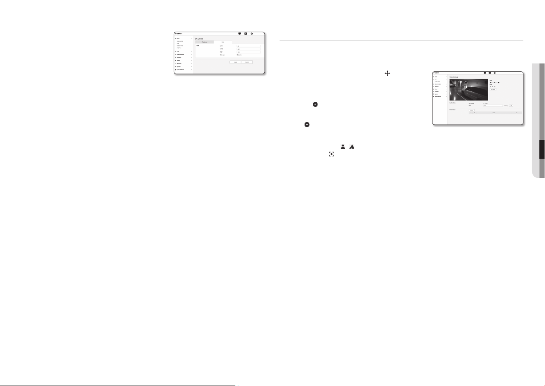
English _39
●●SETUP SCREEN
6. PortClick < >.
7. Type in each item in the Port menu as necessary.
`Neither the port range between 0 and 1023 nor port 3702 is available.
•HTTP : HTTP port used to access the camera via the web
browser.
The default is 80(TCP).
`Setting the HTTP port for Safari and Google Chrome browsers to
65535 is not allowed by security policy.
•HTTPS : In this version, the security of the web communication protocol HTTP is strengthened. It can
be used when you set HTTPS mode in SSL.
The initial value is set to 443(TCP).
`The available setting range is 1024~65535. (For security reasons, in your Safari or Google Chrome browser, you may not use
65535 as your HTTPS port.)
•RTSP : Used to transfer videos in the RTSP mode; the default is 554.
•Timeout : When connecting to RTSP, this function resets the connection if there’s no response for a
certain time.
M
`If changed the HTTP port, the browser exits.
Afterwards, address should contain the newly assigned HTTP port trailing the IP.
ex) IP address: 192.168.1.100, HTTP port : Assigned 8080
http://192.168.1.100:8080
(If HTTP port is set to 80, no need to specify the port number)
`Using RTSP and HTTPS is recommended in order to prevent the image information from being restored.
8. ApplyWhen done, click [ ].
PTZ SETUP
Preset setup
You can save the camera focus/zoom magnification ratio as a preset and run it.
1. PTZ ( From the Setup menu, select the < )> tab.
2. Preset setupClick < >.
3. Adjust the zoom.
•Zoom expansion : Moving the bar to the right or pressing
the [ ] button will expand the magnification ratio of the
screen.
•Zoom reduction : Moving the bar to the left or pressing the
[ ] button will reduce the magnification ratio of the
screen.
4. Adjust the focus.
•Adjust the focus ( / ) : adjust the focus of the screen.
•Auto focus ( ) : Push the button to automatically focus the focal point of the image.
5. Set up whether to use the last location or not, and the hour.
When using the last location, if the hour is set up between 1-600 seconds, the current location value is
saved after the setting time.
After setting up, once the camera is rebooted, then the screen is positioned at the last location.
To add a preset
1. Click the [Set preset] button.
2. Select the preset number to add.
3. Set the name for the preset.
4. Click the [OK] button.
To delete a preset
1. Select the preset number to delete.
2. RemovePress the [ ] button.
To move to a desired preset
1. Select a preset number that you want to move.
2. GoPress the [ ] button.
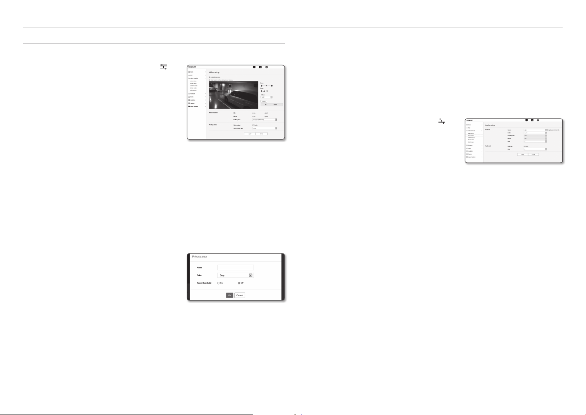
setup screen
40_ setup screen
VIDEO & AUDIO SETUP
Video setup
1. Video & Audio ( )From the Setup menu, select the < >
tab.
2. Video setupClick < >.
3. Adjust the zoom/focus.
4. Video rotationSelect a < > mode.
•Flip : Turn upside down the image that is captured by the
camera.
•Mirror : Flip horizontal the image that is captured by the
camera.
•Hallway view : Rotates the video captured by the camera
according to the set angle.
You can rotate the video 0, 90 or 270 degrees.
`If you change settings, the browser window will be closed and the camera restarted. Please access again later.
5. Specify whether to use the analog video output function.
`To decrease the performance reduction, the usage should only be unlocked after installation.
6. Select the video type.
7. Specify the privacy zone.
`You can set the pattern of the privacy area either to Opaque or Mosaic.
8. ApplyWhen done, click [ ].
To set the privacy zone
You can specify a certain area of the camera video to be protected for your privacy.
1. Enable Privacy areaSet it to < >.
2. ApplyClick [ ].
3. Drag the mouse over the image to select an area.
4. Enter the name and select the color.
5. Make sure the area on the screen matches the area you want
to set, and enter a name.
If you do not want to use the zoom display limit function,
select <Off> and press the [
OK] button.
If the displayed area and set area are different, press the [
Cancel] button and set it again.
6. If you want to use the zoom display limit function, select <
On> and press the [
OK] button.
Then, a popup window will appear as the privacy area is set. At this time, move the zoom to the desired
zoom position and press the [
OK] button.
To cancel the privacy area setting, press the [
Cancel] button and set it again.
7. DeleteIf you want to delete a name in the list, select it and click [ ].
8. To change the pattern of the configure privacy area, select the pattern from the pattern list and click the
[Apply] button.
M
`For the privacy area, the privacy setting is enabled only under 12x zoom without using the DIS feature.
`In the privacy area where the zoom display limit function is applied, [ ] will be displayed after the set name. ZOOM
Audio setup
You can configure the I/O settings of the audio source from the camera.
1. Video & Audio ( From the Setup menu, select the < )>
tab.
2. Audio setupClick < >.
3. Set the audio input value.
•Source : Sets the audio input.
- Internal microphone : Built-in microphone embedded in
the camera.
- Line : Connect the cable to the audio device.
- External microphone : Uses an external microphone.
•Apply power to Ext. Mic. : Select this check box when the external microphone is not powered, and the
power will be supplied from the camera to the microphone. You can configure settings when selecting
< >.External microphone
•Codec : Specify the audio codec.
- G.711 : A audio codec standard, it uses 64 Kbps PCM (Pulse Code Modulation) encoding.
ITU standard audio codec that is adequate for digital voice transfer in PSTN network or through a
PBX.
- G.726 : ITU standard audio codec applying ADPCM (Adaptive Differential Pulse Code Modulation) for
variable bit rates of 40/32/24/16 Kbps to 64 Kbps PCM encoding.
- AAC : Acronym of Advanced Audio Coding, which is an international standard designed to be the
successor of the MP3 format. You can use audio at a higher sampling rate than when you use the
existing G.711 or G.726 codec.
•Sampling rate : Refers to the number of times of sampling when digitalizing an analog soundtrack. The
higher this value is, the better the sound quality is.
•Bitrate : Set the bit rate to differentiate compression ratio if using G.726 codec.
•Gain : Specify the audio input amplification.
J
`Sound quality deterioration or howling may occur if the loudness of the sound source or gain value were set excessively.
4. Set the audio output level.
•Enable : Sets whether to use audio output.
•Gain : Specify the audio output amplification.
5. ApplyWhen done, click [ ].

English _41
●●SETUP SCREEN
Camera setup
You can change the camera settings according to the environment where the camera is located.
1. Video & Audio ( From the Setup menu, select the < )>
tab.
2. Camera setupClick < >.
3.
Configure the settings as necessary of :
Image preset mode,
Sensor, SSDR, White balance, Back light, Exposure, Day/
Night, Special, OSD, Focus, Heater, IR
4. ApplyWhen done, click [ ].
`
If a certain time (timeout: 240s) is elapsed
with your not pressing the
[ ]Apply
button after changing the settings, your changes will not be
applied.
If you want to set an image preset
Users can set presets easily.
The selected image preset mode will be in operation during the configured period, but at other times the
values configured in the user preset mode are reflected.
1. Select a desired mode from the image presets.
•High definition : This is the factory setting for your camera.
Select it for video recording, focusing on reproducibility.
•Motion : Record a moving object clearly. If there are many
moving objects, such as on a road or in a crowded place
like a museum, select this option.
J
`Noise level can increase in a low illumination environment, and
sensitivity can go down.
•Noise reduction : Select this when you need a video with low noise in the low illumination environment.
•Bright video : This makes the dark area in a full video brighter.
J
`Video contracts effects are reduced.
•Motion & Noise reduction : Use this when there are many moving objects, such as on a road or
in a crowded place like a museum, or when you need a video with low noise in a low illumination
environment.
•Motion & Bright video : Use it when there are many moving objects, such as on a road or in a crowded
place like a museum, or when you need to make a dark area in full video brighter.
•Vivid video : Makes the entire video displayed in vivid colors.
J
`The contrast of the video reduces and the color reproducibility becomes low.
•User preset : Select it if you want to display video with settings chosen by you.
J
`When selecting a mode other than the preset mode, you can’t set the shutter speed, AGC, SSDR, SSNR and color.
2. Set the camera item for each image preset mode.
3. Activation timeSet the < >.
•Off : Your camera will execute a specific image preset operation at all times.
•Only scheduled time : Your camera will execute a specific image preset operation for the time period set
by you on each date.
4. Click the [ ] button.
5. Mode TimeSet the < > and < >.
6. ApplyWhen done, click [ ].
Initial setting for each image preset mode
Image preset Minimum
shutter
Maximum
shutter
Prefer
shutter AGC SSDR COLORSSNR 2D SSNR 3D
High definition 1/5 1/12000 1/60(1/50) Default
(High) Default (12) Default (12) Default (12) Default (50)
Motion 1/30 1/12000 1/200 Default
(High) Default (12) 4 4 Default (50)
Noise reduction 1/15 1/12000 1/60(1/50) Middle Default (12) Default (12) Default (12) Default (50)
Bright video 1/5 1/12000 1/60(1/50) Default
(High) 18 Default (12) Default (12) Default (50)
Motion & Noise
reduction 1/30 1/12000 1/200 Middle Default (12) 4 4 Default (50)
Motion & Bright video 1/30 1/12000 1/200 Default
(High) 18 4 4 Default (50)
Vivid video 1/5 1/12000 1/60(1/50) Default
(High) 18 Default (12) Default (12) 90
User preset Manual Manual Manual Manual Manual Manual Manual Manual
M
`The preset setup functions as an aid to users to configure setup. If you don’t want the preset function, deactivate it before
use.
`If you change the image preset, only shutter/AGC/SSDR/SSNR/COLOR are reset to the default value for each model.
`The “Camera Setting” value does not change between presets.

setup screen
42_ setup screen
To Set the Sensor
It specifies how many frames the camera CMOS sensor will capture per second.
1. SensorSelect < >.
2. ModeSelect < >.
M
`Refer to “Video profile” for the framerate setup range of the <Video
profile> according to mode setup. (Page 35)
To Set SSDR
In a scene where the difference between bright and dark is severe, you can increase the brightness of the
dark area alone to regulate the overall brightness.
1. SSDRSelect < >.
2. EnableSet the SSDR use option to < >.
3. Level D-RangeConfigure the < > and < > settings as
necessary.
•Level : Adjust the level of the dynamic range.
•D-Range : Select the amplitude area of the dynamic range.
To Set White Balance
You can correct the image colors based on white under any lighting conditions.
1. White balanceSelect < >.
2. ModeSelect < >.
•ATW : Corrects the colors of the camera video
automatically.
•Manual : You can adjust the red and blue gains of the
camera video manually.
•Outdoor : Automatically corrects the video colors of the camera to be optimized to the outdoor
environment.
•Indoor : Automatically corrects the video colors of the camera to be optimized to the indoor
environment.
•AWC : Corrects the colors of the camera video to be optimized to the current lighting condition and
screen mode.
To obtain the optimal condition for the current lighting, put the focus of the camera to a white paper
and press the [ ] button. If the lighting environment is changed, you should readjust the settings Set
accordingly.
M
`In AWC mode, click the [ ] button if you want to keep the white balance level of the current image.Set
J
`The white balancing may not work properly in the following conditions:
If this is the case, switch to AWC mode.
-If the surrounding condition of the object is out of the temperature correction range
ex) Clear sky, sunset
-If the surrounding of the object is dark
-If the focus of the camera directly faces the florescent lighting or if the camera is installed in a place of variable
illumination, the white balancing operation may be unstable.
To Set BLC
You can specify a desired area on the video manually and set the area to be displayed more clearly.
1. Back lightSelect < >.
2. Mode BLCSet < > to < >.
3. BLC levelSet < >.
You can change the level to adjust the brightness of the
monitoring area.
4. Top, Bottom, Left, RightSet the < > levels to specify the
target area.
J
`When setting BLC, a green box is displayed on the screen for 15 seconds.
`To prevent malfunction at the time of BLC setup, the vertical space of the BLC area should be over 40 and below 60 while the
horizontal space over 30 and below 60.
HLC (Highlight Compensation) Setup
If a strong light like a streetlamp or vehicle headlight points toward the camera, the area can be set to be cut
off to prevent a saturated area on the monitor.
1. Back lightSelect < >.
2. Mode HLCSet < > to < >.
•HLC level : This adjusts the brightness level to cut off the
highlighted area.
•Mask
- Off : Does not block an area with a brightness that is a
certain level or higher.
- On : Always blocks an area with a brightness that is a
certain level or higher.
- Night only : No blocked area is generated if the
surrounding environment becomes dark to a certain level.
- All day : No blocked area is generated if the surrounding environment becomes dark or bright to a
certain level.
•Mask color : You can select the color of the blocked area.
•Mask tone : You can adjust the brightness of the color in the blocked area.
•Dimming : Detects an area on the screen with strong light, and adjusts the brightness and reduces the
saturated area.
3. Top, Bottom, Left, RightSet the < > levels to specify the target area.
J
`When setting HLC, a green box is displayed on the screen for 15 seconds.
`To prevent malfunction at the time of HLC setup, the vertical space of the HLC area should be over 40 and below 60 while
the horizontal space over 30 and below 60.
M
`At night operation, this function will be activated only if the incoming highlight exceeds a certain area in a low contrast
environment.
`At night operation, HLC will not function in too a bright or too a dark scene.
`During daytime operation, HLC will not work in dark condition.
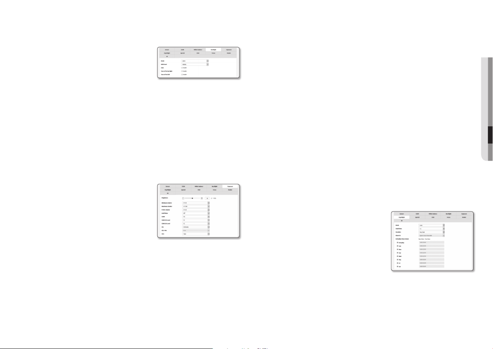
English _43
●●SETUP SCREEN
To Set WDR
It displays a sharp image of the objects in a scene where both bright and dark areas exist.
1. Back lightSelect < >.
2. Mode WDRSet < > to < >.
3. Select each item and set it properly.
•WDR level : Adjusts the intensity of backlight
compensation.
•Auto : Detects the surrounding environment and
automatically uses backlight compensation.
•Turn off in low light : Does not use automatic backlight compensation when detecting a dark
environment.
•Turn off in B/W : Does not use backlight compensation when switching to B/W mode.
J
`It is recommended to use WDR in the indoor environment.
`Noise may exist between the dark area and the bright area in the WDR mode.
`With WDR mode On or Off, the minimum, maximum and user-preferred shutter value will be reset.
`If you use the P aperture lens manually or a shaking preventive shutter, the WDR performance is partially limited.
`In WDR mode, noise may occur in the motion area.
To Set Exposure
You can adjust the exposure level of the camera.
1. ExposureSelect < >.
2. Select each item and set it properly.
•Brightness : Adjust the screen brightness.
•Minimum shutter : The limit of the longest exposure time.
`Shutter is the mode to set up the range of the sensor exposure time
which will specify the upper and lower limits for the electronic shutter
movement.
`The framerate may be reduced in the dark condition if Shutter has a
lower value than specified in the Sensor mode.
•Maximum shutter : The limit of the shortest exposure time.
•Prefer shutter : Sets an appropriate exposure duration that is preferentially applied within the exposure
duration range.
•Anti flicker : It prevents screen flickering incurring from the dissonance between the surrounding lighting
and the frequency.
•SSNR
- On : Noise of the video is removed.
- Wise NR : Automatically adjusts the nose reduction level when there is a moving object in the video
to increase the identifiability.
•SSNR 2D Level : Adjusts the 2DNR level.
- 2DNR : This is a method of reducing the noise by using the adjacent pixel information on a single
video frame.
If you increase the level, the noise will be reduced but the video may be blurred.
•SSNR 3D Level : Adjusts the 3DNR level.
- 3DNR : This is a method of reducing the noise by using multiple video frames.
If you increase the level, the noise will be reduced but the video may drag.
•Iris : Select it to set the camera lens to auto or manual.
- DC(Auto) : The iris is automatically adjusted to the amount of the surrounding light.
- Manual : Sets the iris F-No to manual.
•Iris F-No : Set up the F value of the iris.
•AGC : Select AGC Control mode.
Adjust the gain value of the video (that, in particular, was recorded at a low contrast scene and had a
lower brightness level than normal) to control the video brightness.
J
`The image exposure can be saturated depending on the Shutter setup range.
`It may take some time from the point when you enable the WiseNR mode to the point when the effect is actually applied/
released.
`When the WiseNR mode is enabled, the identifiability of the video will be improved, but the noise may be increased as
well.
`In a bright environment with less noise, WiseNR may not be so effective.
`With intelligent NR enabled, the motion detection in the video will be performed according to the operation conditions
of the motion detection event, as motion detection uses the motion detection function internally. For more information,
please refer to “ ” (page Motion detection 54).
To Set Day/Night
1. Day/NightSelect < >.
2. Select each item and set it properly.
•Mode : Mode is used to adjust the color of Color or Black
and White.
- Color : The video is always output in color.
- B/W : The video is always output in black and white.
- Auto : Normally, it is set to Color but to B&W under low
luminance at night.
`If AGC of the < > menu is set to < >, the day/night Exposure Off
mode cannot be set to <Auto>.
- External : It controls the color of the video when the alarm input terminal is synchronized with an
external device.
- Schedule : Set the time during which the camera is operated in the color mode.

setup screen
44_ setup screen
•Dwell Time : It specifies the period for which the selected brightness condition must be maintained to
switch the lighting mode from Day to Night or vice versa.
•Duration : It specifies the interval of lighting mode conversion.
•Alarm in : The video is set to Color or B/W as the alarm sensor is open or closed.
`If the Day/Night mode is set to External Input, the alarm input function of the Event-Alarm Input page is disabled.
•Activation time(Color) : It specifies the schedule for color mode operation.
`If it is set, the Color mode is maintained from 00 second of the starting time to 59 second of the ending time.
J
`When you switch to day/night mode, motion detection mode does not work.
To Setup Special
1. SpecialSelect < >.
2. Select each item and set it properly.
•DIS : Compensates the image automatically when it is seen
to shake for stable image output.
M
`Mitigate the degree of image vibration when the camera
vibrates due to the external factors such as wind.
J
`In the following cases, DIS is not available to use.
-
When using tempering event
-
When using motion detection event
-
When using IVA event
•Sharpness : Adjust the overall sharpness of the image.
If selecting < >, you can adjust the sharpness of the image.On
•Sharpness level : The higher the level is, the sharper and clearer the outline of the image becomes.
•Gamma : Adjust the contrast of the image.
•Contrast : Adjusts the difference between the darkest area and the brightest area in the video.
•Color level : Adjust the strength of video color.
•Defog : Compensate the video in the foggy or cloudy weather.
It is set to < > as a default. Specials are used when the video looks blurry in the foggy weather.Off
- Off : Disable the fog elimination function.
- Auto : The image is automatically compensated according to the foggy level. Adjust < > Defog level
to be more effective.
- Manual : The user manually sets the amount of compensation for each image.
J
`If the defog mode is set to < >, the performance is proportional to the fog level. To keep the set defog level without Auto
regard to the fog level, set the defog mode to <Manual>.
`If the manual defog level is high in a thin fog, the image may become too dark.
•Defog level : Control the defog level.
To Set OSD
1. OSDSelect < >.
2. Select each item and set it properly.
•Camera title : It specifies the name of the camera to be
displayed on the screen.
Select the < > check box to add a camera name.Use
- Add : Click the < > button and you can add a Add
total of 5 lines, 17 characters per line and a total of 85
characters.
- Preview : Click the <Preview> button to check the
name of camera that will be displayed on the screen.
•Camera title X, Y : It specifies the position of the camera name on the screen.
•Date & time : Set the time display and date formats on the screen.
•Date & Time X, Y : Specify the position of time display on the screen.
•Weekday overlay : Specify the use of date display date on the screen.
•Size : Sets the size of OSD to small/medium/large.
•Color : Sets the color of the OSD to white/red/blue/green/black/gray.
•Transparency : Sets the transparency of OSD to opaque / low / middle / high.
•Zoom magnification : Display zoom magnification on the screen.
•Preset name : Specify whether or not to display preset name on the screen.
J
`A position-adjustable item (Camera title, Date & Time) may not be displayed normally if it overlaps with another fixed OSD
item.
`Multilingual other than English: Input only in the selected language is available.
Focus Setup
1. Select <Focus>.
2. Select each item and set it properly.
•Mode
- Manual : The focus will be adjusted manually according
to the zoom factor.
- Auto : The focus will be adjusted automatically
according to the zoom factor.
- One Shot AF : Auto Focus will be performed once after the zooming operation.
•Digital zoom : Specify the use of digital zoom.
`Digital zoom cannot be used if DIS is used.
•Digital zoom limit : Specify the limit of the digital zoom.
•Zoom tracking : When using the zoom function, this sets how the focus is interconnected.
- Auto tracking : It will control (detect and correct) the zooming operation to keep fitting the focus.
- Tracking : The zooming operation will be guided by the focus track.
•Zoom speed : Adjust the zoom tracking speed.
•Init. lens : Reset the lens to prevent the step-out in zoom mode.

English _45
●●SETUP SCREEN
J
`The auto focus function might not work properly under any of the following conditions:
-Bright or flashing lights (ex.- neon sign)
-Low illumination of the target area
-Slow-shutter action
-Dark object
-Excessive illumination of the target area
-If a short-distance object and a long-distance object are in the target area
-If there is no contract gap (sky, wall, etc.)
-If the camera is taking a picture of a thin horizontal line
`In the auto focus mode, because the camera focuses on the object at the center of the area, other objects which are not in
the center can be out of focus.
To set the heater
1. HeaterSelect < >.
When frost forms, the user can click the button and turn on
the heater for 30 minutes to remove the frost.
J
`At low temperature when frost is likely to form, the heater is always
on; at a high temperature where the product can be affected by it, it
does not operate, even when the request to operate has been sent.
To Set IR (XNO-6120R/XNV-6120R)
1. IRSelect < >.
2. Select each item and set it properly.
•Mode : When the IR indicator turns on in B/W mode, the
screen will be protected from saturation on the center area
so that you can identify a short-distant object.
- Off : IR mode will be disabled.
- Auto1 : Adjust the IR brightness according to the brightness of the object on the center screen.
- Auto2 : The brightness of the IR is automatically adjusted according to the brightness of the object
located in the middle or periphery of the screen.
- Manual : Adjust the IR brightness manually.
•Level : Adjust the level of IR in manual mode.
M
`This applies only for the IR model.
Smart codec
Set a desired area of the video incoming from the camera as ROI area and specify the detection sensitivity for
the area.
1. Video & Audio ( From the Setup menu, select the < )>
tab.
2. Smart codecClick < >.
3. Adjust the zoom and focal point.
4. Set the image quality.
The ROI area will be displayed in the specified quality.
5. Specify an area of interest to monitor manually.
6. Select a desired area with the mouse pointer, and drag it as
much as you want.
`You can specify up to 5 distinct areas.
7. To cancel all the settings for the area, click the [ ] button.Clear
8. ApplyWhen done, click [ ].
J
`The Smart codec will not be active if it is set to < > in < >. (page Off Video profile 35)
WiseStream
This is the feature that optimizes the size of the video data by reducing the bit rate through increasing the
compression of the parts where there is no movement after detecting the complexity in the image.
1. Video & Audio ( From the Setup menu, select the < )>
tab.
2. WiseStreamClick < >.
3. Select wise stream mode.
- Off : Wise Stream function will be disabled.
- Low ~ High : use the wise stream to select the bit rate
reduction level.
4. ApplyWhen done, click [ ].
J
`In the following cases, the WiseStream function may malfunction.
-Sudden screen switch may cause distortion of the video.
-It is not appropriate to use in an environment with too much movement and motion on the screen.
Produkt Specifikationer
| Mærke: | Hanwha |
| Kategori: | Overvågningskamera |
| Model: | XNV-6120 |
Har du brug for hjælp?
Hvis du har brug for hjælp til Hanwha XNV-6120 stil et spørgsmål nedenfor, og andre brugere vil svare dig
Overvågningskamera Hanwha Manualer

24 September 2024
24 September 2024
24 September 2024
1 September 2024
31 August 2024
30 August 2024
30 August 2024
30 August 2024
30 August 2024
30 August 2024
Overvågningskamera Manualer
- Overvågningskamera Bosch
- Overvågningskamera Denver
- Overvågningskamera Sony
- Overvågningskamera Canon
- Overvågningskamera Netis
- Overvågningskamera Samsung
- Overvågningskamera Panasonic
- Overvågningskamera Extech
- Overvågningskamera Moog
- Overvågningskamera TP-Link
- Overvågningskamera Philips
- Overvågningskamera Vitek
- Overvågningskamera Gigaset
- Overvågningskamera Pioneer
- Overvågningskamera Mitsubishi
- Overvågningskamera Braun
- Overvågningskamera Logitech
- Overvågningskamera Emos
- Overvågningskamera Google
- Overvågningskamera Technaxx
- Overvågningskamera HP
- Overvågningskamera Waeco
- Overvågningskamera Garmin
- Overvågningskamera Sanyo
- Overvågningskamera Grundig
- Overvågningskamera D-Link
- Overvågningskamera Arlo
- Overvågningskamera Motorola
- Overvågningskamera Asus
- Overvågningskamera Toshiba
- Overvågningskamera Pyle
- Overvågningskamera Kodak
- Overvågningskamera Furrion
- Overvågningskamera InFocus
- Overvågningskamera Nedis
- Overvågningskamera Friedland
- Overvågningskamera Abus
- Overvågningskamera Planet
- Overvågningskamera Adj
- Overvågningskamera Hama
- Overvågningskamera Creative
- Overvågningskamera Thomson
- Overvågningskamera Belkin
- Overvågningskamera Edimax
- Overvågningskamera Burg Wächter
- Overvågningskamera Clas Ohlson
- Overvågningskamera DataVideo
- Overvågningskamera Strong
- Overvågningskamera TRENDnet
- Overvågningskamera Smartwares
- Overvågningskamera Trevi
- Overvågningskamera Trust
- Overvågningskamera Laserliner
- Overvågningskamera Blaupunkt
- Overvågningskamera JVC
- Overvågningskamera Honeywell
- Overvågningskamera Uniden
- Overvågningskamera Buffalo
- Overvågningskamera Linksys
- Overvågningskamera Megasat
- Overvågningskamera Cisco
- Overvågningskamera EZVIZ
- Overvågningskamera König
- Overvågningskamera Elro
- Overvågningskamera Gembird
- Overvågningskamera Powerfix
- Overvågningskamera Alpine
- Overvågningskamera Netgear
- Overvågningskamera Maginon
- Overvågningskamera Yale
- Overvågningskamera Withings
- Overvågningskamera Nest
- Overvågningskamera Kerbl
- Overvågningskamera Vtech
- Overvågningskamera Exibel
- Overvågningskamera Genie
- Overvågningskamera Vaddio
- Overvågningskamera Bresser
- Overvågningskamera Western Digital
- Overvågningskamera Anker
- Overvågningskamera Digitus
- Overvågningskamera Zebra
- Overvågningskamera Jensen
- Overvågningskamera Alecto
- Overvågningskamera Flamingo
- Overvågningskamera Rollei
- Overvågningskamera Olympia
- Overvågningskamera Xiaomi
- Overvågningskamera Niceboy
- Overvågningskamera Aiptek
- Overvågningskamera Schneider
- Overvågningskamera B/R/K
- Overvågningskamera Marmitek
- Overvågningskamera Tesla
- Overvågningskamera Imou
- Overvågningskamera Ricoh
- Overvågningskamera Nexxt
- Overvågningskamera Aida
- Overvågningskamera APC
- Overvågningskamera Foscam
- Overvågningskamera Lorex
- Overvågningskamera Ikan
- Overvågningskamera Velleman
- Overvågningskamera LevelOne
- Overvågningskamera Marshall
- Overvågningskamera FLIR
- Overvågningskamera Perel
- Overvågningskamera Swann
- Overvågningskamera Vivotek
- Overvågningskamera Joblotron
- Overvågningskamera JUNG
- Overvågningskamera ORNO
- Overvågningskamera Binatone
- Overvågningskamera ZyXEL
- Overvågningskamera Fortinet
- Overvågningskamera Netatmo
- Overvågningskamera Tenda
- Overvågningskamera Eufy
- Overvågningskamera Ring
- Overvågningskamera M-e
- Overvågningskamera Overmax
- Overvågningskamera Somfy
- Overvågningskamera Y-cam
- Overvågningskamera Hikvision
- Overvågningskamera Monacor
- Overvågningskamera ION
- Overvågningskamera Raymarine
- Overvågningskamera Ubiquiti Networks
- Overvågningskamera AVerMedia
- Overvågningskamera EnGenius
- Overvågningskamera Reolink
- Overvågningskamera Grandstream
- Overvågningskamera Trebs
- Overvågningskamera EVE
- Overvågningskamera Renkforce
- Overvågningskamera Marshall Electronics
- Overvågningskamera Manhattan
- Overvågningskamera SPC
- Overvågningskamera Caliber
- Overvågningskamera Pentatech
- Overvågningskamera Switel
- Overvågningskamera AVtech
- Overvågningskamera LogiLink
- Overvågningskamera Orion
- Overvågningskamera Eminent
- Overvågningskamera Kramer
- Overvågningskamera QSC
- Overvågningskamera Brilliant
- Overvågningskamera Lanberg
- Overvågningskamera Hive
- Overvågningskamera Siedle
- Overvågningskamera BirdDog
- Overvågningskamera Evolveo
- Overvågningskamera Genius
- Overvågningskamera KJB Security Products
- Overvågningskamera Valueline
- Overvågningskamera Provision-ISR
- Overvågningskamera Quantum
- Overvågningskamera Axis
- Overvågningskamera ACTi
- Overvågningskamera CRUX
- Overvågningskamera Avanti
- Overvågningskamera Vimar
- Overvågningskamera Aluratek
- Overvågningskamera Dahua Technology
- Overvågningskamera Chacon
- Overvågningskamera SereneLife
- Overvågningskamera ZKTeco
- Overvågningskamera AG Neovo
- Overvågningskamera Stabo
- Overvågningskamera EtiamPro
- Overvågningskamera First Alert
- Overvågningskamera Speco Technologies
- Overvågningskamera Boss
- Overvågningskamera Broan
- Overvågningskamera Conceptronic
- Overvågningskamera Avidsen
- Overvågningskamera Crestron
- Overvågningskamera Lindy
- Overvågningskamera Kogan
- Overvågningskamera AVMATRIX
- Overvågningskamera Delta Dore
- Overvågningskamera Promise Technology
- Overvågningskamera Sitecom
- Overvågningskamera DiO
- Overvågningskamera Minox
- Overvågningskamera Intellinet
- Overvågningskamera V-TAC
- Overvågningskamera Qian
- Overvågningskamera August
- Overvågningskamera IDIS
- Overvågningskamera Geovision
- Overvågningskamera Schwaiger
- Overvågningskamera Steren
- Overvågningskamera Elmo
- Overvågningskamera AViPAS
- Overvågningskamera UniView
- Overvågningskamera Equip
- Overvågningskamera Alfatron
- Overvågningskamera REVO
- Overvågningskamera Aqara
- Overvågningskamera Ernitec
- Overvågningskamera Setti+
- Overvågningskamera BZBGear
- Overvågningskamera PTZ Optics
- Overvågningskamera AVer
- Overvågningskamera Ferguson
- Overvågningskamera Moxa
- Overvågningskamera Inovonics
- Overvågningskamera Bea-fon
- Overvågningskamera Profile
- Overvågningskamera WyreStorm
- Overvågningskamera Allnet
- Overvågningskamera Aldi
- Overvågningskamera Airlive
- Overvågningskamera Aritech
- Overvågningskamera ACME
- Overvågningskamera KlikaanKlikuit
- Overvågningskamera Marquant
- Overvågningskamera Ednet
- Overvågningskamera Lumens
- Overvågningskamera Hombli
- Overvågningskamera Naxa
- Overvågningskamera Miniland
- Overvågningskamera Xavax
- Overvågningskamera Gira
- Overvågningskamera Interlogix
- Overvågningskamera DSC
- Overvågningskamera Boyo
- Overvågningskamera Iget
- Overvågningskamera EverFocus
- Overvågningskamera Adesso
- Overvågningskamera Satel
- Overvågningskamera Notifier
- Overvågningskamera Monoprice
- Overvågningskamera Beafon
- Overvågningskamera Chuango
- Overvågningskamera MicroView
- Overvågningskamera ETiger
- Overvågningskamera Videcon
- Overvågningskamera INSTAR
- Overvågningskamera Advantech
- Overvågningskamera Digital Watchdog
- Overvågningskamera Moen
- Overvågningskamera Ganz
- Overvågningskamera MEE Audio
- Overvågningskamera Mobotix
- Overvågningskamera Kwikset
- Overvågningskamera Ikegami
- Overvågningskamera Leviton
- Overvågningskamera Pelco
- Overvågningskamera Approx
- Overvågningskamera ClearOne
- Overvågningskamera Ebode
- Overvågningskamera Oplink
- Overvågningskamera Dorr
- Overvågningskamera Sonic Alert
- Overvågningskamera Linear PRO Access
- Overvågningskamera Summer Infant
- Overvågningskamera SMC
- Overvågningskamera Topica
- Overvågningskamera Iiquu
- Overvågningskamera Verint
- Overvågningskamera Brinno
- Overvågningskamera Rostra
- Overvågningskamera Caddx
- Overvågningskamera Spyclops
- Overvågningskamera EKO
- Overvågningskamera Kguard
- Overvågningskamera Woonveilig
- Overvågningskamera Accsoon
- Overvågningskamera Mobi
- Overvågningskamera Surveon
- Overvågningskamera Hollyland
- Overvågningskamera Epcom
- Overvågningskamera Indexa
- Overvågningskamera Lutec
- Overvågningskamera Whistler
- Overvågningskamera ClearView
- Overvågningskamera VideoComm
- Overvågningskamera IMILAB
- Overvågningskamera 3xLOGIC
- Overvågningskamera Inkovideo
- Overvågningskamera Weldex
- Overvågningskamera SecurityMan
- Overvågningskamera Mach Power
- Overvågningskamera Canyon
- Overvågningskamera CNB Technology
- Overvågningskamera Tapo
- Overvågningskamera Aigis
- Overvågningskamera Exacq
- Overvågningskamera Brickcom
- Overvågningskamera Laxihub
- Overvågningskamera Securetech
- Overvågningskamera EFB Elektronik
- Overvågningskamera NetMedia
- Overvågningskamera Videotec
- Overvågningskamera Illustra
- Overvågningskamera Atlona
- Overvågningskamera Nivian
- Overvågningskamera Arenti
- Overvågningskamera E-bench
- Overvågningskamera Blow
- Overvågningskamera Syscom
- Overvågningskamera Tecno
- Overvågningskamera Night Owl
- Overvågningskamera Guardzilla
- Overvågningskamera Astak
- Overvågningskamera Blink
- Overvågningskamera Milestone Systems
- Overvågningskamera Zavio
- Overvågningskamera Campark
- Overvågningskamera IPX
- Overvågningskamera Dedicated Micros
- Overvågningskamera Hamlet
- Overvågningskamera Annke
- Overvågningskamera Qoltec
- Overvågningskamera Digimerge
- Overvågningskamera Feelworld
- Overvågningskamera Wisenet
- Overvågningskamera Infortrend
- Overvågningskamera Epiphan
- Overvågningskamera HiLook
- Overvågningskamera Compro
- Overvågningskamera Vimtag
- Overvågningskamera Sonoff
- Overvågningskamera Gewiss
- Overvågningskamera Alula
- Overvågningskamera Insteon
- Overvågningskamera Costar
- Overvågningskamera ALC
- Overvågningskamera Security Labs
- Overvågningskamera Comtrend
- Overvågningskamera Seneca
- Overvågningskamera Avigilon
- Overvågningskamera American Dynamics
- Overvågningskamera Vosker
- Overvågningskamera Sentry360
- Overvågningskamera Owltron
- Overvågningskamera Petcube
- Overvågningskamera Enabot
- Overvågningskamera Luis Energy
- Overvågningskamera Sir Gawain
- Overvågningskamera VisorTech
- Overvågningskamera Atlantis Land
- Overvågningskamera B & S Technology
- Overvågningskamera I3International
- Overvågningskamera Ecobee
- Overvågningskamera Turing
- Overvågningskamera Wasserstein
- Overvågningskamera Qolsys
- Overvågningskamera Control4
- Overvågningskamera Milesight
- Overvågningskamera GVI Security
- Overvågningskamera Conbrov
- Overvågningskamera HuddleCamHD
- Overvågningskamera Defender
- Overvågningskamera IOIO
- Overvågningskamera BIRDFY
- Overvågningskamera I-PRO
- Overvågningskamera DVDO
- Overvågningskamera TCP
- Overvågningskamera Bolin Technology
- Overvågningskamera Nextech
- Overvågningskamera Tuya
- Overvågningskamera Bolide
- Overvågningskamera Telycam
- Overvågningskamera Arecont Vision
- Overvågningskamera Schlage
Nyeste Overvågningskamera Manualer
7 April 2025
7 April 2025
6 April 2025
29 Marts 2025
28 Marts 2025
20 Marts 2025
20 Marts 2025
20 Marts 2025
13 Marts 2025
8 Marts 2025