Hikvision DS-2DE5425IW-AE Manual
Hikvision
Overvågningskamera
DS-2DE5425IW-AE
Læs nedenfor 📖 manual på dansk for Hikvision DS-2DE5425IW-AE (117 sider) i kategorien Overvågningskamera. Denne guide var nyttig for 44 personer og blev bedømt med 4.5 stjerner i gennemsnit af 2 brugere
Side 1/117

Network PTZ Camera
User Manual

User Manual of Network Z Camera PT
© Hikvision
i
User Manual
COPYRIGHT © 2018 Hangzhou Hikvision Digital Technology Co., Ltd.
ALL RIGHTS RESERVED.
Any and all informaon, including, among others, wordings, pictures, graphs are the properes of
Hangzhou Hikvision Digital Technology Co., Ltd. or its subsidiaries (hereinaer referred to be
“Hikvision”) “ ”. This user manual (hereinaer referred to be the Manual ) cannot be reproduced,
changed, translated, or distributed, parally or wholly, by any means, without the prior wrien
permission of Hikvision. Unless otherwise spulated, Hikvision does not make any warranes,
guarantees or representaons, express or implied, regarding to the Manual.
About this Manual
This Manual is applicable to Network PTZ camera.
The Manual includ instrucons for using and managing the product. Pictures, charts, images and all es
other informaon hereinaer are for descripon and explanaon only. The informaon contained in
the Manual is subject to change, without noce, due to rmware updates or other reasons. Please
nd the latest version in the company website ( ). hp://overseas.hikvision.com/en/
Please use this user manual under the guidance of professionals.
Trademarks Acknowledgement
and other Hikvision’s trademarks and logos are the properes of Hikvision in various
jurisdicons. Other trademarks and logos menoned below are the properes of their respecve
owners.
Legal Disclaimer
TO THE MAXIMUM EXTENT PERMITTED BY APPLICABLE LAW, THE PRODUCT DESCRIBED, WITH ITS
HARDWARE, SOFTWARE AND FIRMWARE, IS PROVIDED AS IS , WITH ALL FAULTS AND ERRORS, AND “ ”
HIKVISION MAKES NO WARRANTIES, EXPRESS OR IMPLIED, INCLUDING WITHOUT LIMITATION,
MERCHANTABILITY, SATISFACTORY QUALITY, FITNESS FOR A PARTICULAR PURPOSE, AND
N -INFRINGEMENT OF THIRD PARTY. IN NO EVENT WILL HIKVISION, ITS DIRECTORS, OFFICERS, ON
EMPLOYEES, OR AGENTS BE LIABLE TO YOU FOR ANY SPECIAL, CONSEQUENTIAL, INCIDENTAL, OR
INDIRECT DAMAGES INCLUDING, AMONG OTHERS, DAMAGES FOR LOSS OF BUSINESS PROFITS, ,
BUSINESS INTERRUPTION, OR LOSS OF DATA OR DOCUMENTATION, IN CONNECTION WITH THE USE
OF THIS PRODUCT, EVEN IF HIKVISION HAS BEEN ADVISED OF THE POSSIBILITY OF SUCH DAMAGES.
REGARDING TO THE PRODUCT WITH INTERNET ACCESS, THE USE OF PRODUCT SHALL BE WHOLLY AT
YOUR OWN RISKS. HIKVISION SHALL NOT TAKE ANY RESPONSIBILITES FOR ABNORMAL OPERATION,
PRIVACY LEAKAGE OR OTHER DAMAGES RESULTING FROM CYBER ATTACK, HACKER ATTACK, VIRUS
INSPECTION, OR OTHER INTERNET SECURITY RISKS; HOWEVER, HIKVISION WILL PROVIDE TIMELY
TECHNICAL SUPPORT IF REQUIRED.
SURVEILLANCE LAWS VARY BY JURISDICTION PLEASE CHECK ALL RELEVANT LAWS IN YOUR .
JURISDICTION BEFORE USING THIS PRODUCT IN ORDER TO ENSURE THAT YOUR USE CONFORMS THE
APPLICABLE LAW. HIKVISION SHALL NOT BE LIABLE IN THE EVENT THAT THIS PRODUCT IS USED WITH
ILLEGITIMATE PURPOSES.

User Manual of Network PTZ Camera
© Hikvision
ii
IN THE EVENT OF ANY CONFLICTS BETWEEN THIS MANUAL AND THE APPLICABLE LAW, THE LATER
PREVAILS.
0505071080328

User Manual of Network PTZ Camera
© Hikvision
iii
Regulatory Informaon
FCC Informaon
Please take attenon that changes or modicaon not expressly approved by the party
responsible for compliance could void the user’s authority to operate the equipment.
FCC compliance: This equipment has been tested and found to comply with the limits for a Class
A digital device, pursuant to part 15 of the FCC Rules. These limits are designed to provide
reasonable protecon against harmful interference when the equipment is operated in a
commercial environment. This equipment generates, uses, and can radiate radio frequency
energy and, if not installed and used in accordance with the instrucon manual, may cause
harmful interference to radio communications. Operaon of this equipment in a residential area
is likely to cause harmful interference in which case the user will be required to correct the
interference at his own expense.
FCC Condions
This device complies with part 15 of the FCC Rules. Operaon is subject to the following two
conditions:
1. This device may not cause harmful interference.
2. This device must accept any interference received, including interference that may cause
undesired operaon.
EU Conformity Statement
This product and - if applicable - the supplied accessories too are marked with
"CE" and comply therefore with the applicable harmonized European standards
listed under the Low Voltage Directive 2015/35/EU, the EMC Direcve 2014/30/EU,
the RoHS Direcve 2011/65/EU.
2012/19/ (WEEE direcve): Products marked with this symbol cannot be EU
disposed of as unsorted municipal waste in the European Union. For proper
recycling, return this product to your local supplier upon the purchase of
equivalent new equipment, or dispose of it at designated collecon points. For
more informaon see: www.recyclethis.in . fo
2006/66/EC (battery directive): This product contains a baery that cannot be
disposed of as unsorted municipal waste in the European Union. See the product
documentaon for specic battery information. The battery is marked with this
symbol, which may include lettering to indicate cadmium (Cd), lead (Pb), or
mercury (Hg). For proper recycling, return the battery to your supplier or to a designated
collection point. For more informaon see: www.recyclethis.info.
Industry Canada ICES-003 Compliance
This device meets the CAN ICES-3 (A)/NMB-3(A) standards requirements.

User Manual of Network PTZ Camera
© Hikvision
iv
Safety Instrucon
These instrucons are intended to ensure that the user can use the product correctly to avoid
danger or property loss.
The precauon measure is divided into ‘Warnings’ and ‘Cauons’:
Warnings: Serious injury or death may be caused if any of these warnings are neglected.
Cauons: Injury or equipment damage may be caused if any of these cautions are neglected.
Warnings Follow these safeguards to prevent
serious injury or death.
Cauons Follow these precauons to prevent
potenal injury or material damage.
Warnings:
Adopt the power adapter which can meet the safety extra low voltage (SELV) standard The .
power consumpon cannot be less than the required value.
Do not connect several devices to one power adapter as an adapter overload may cause
over-heating and can be a re hazard.
When the product is installed on a wall or ceiling, the device should be rmly xed.
To reduce the risk of re or electrical shock, do not expose the indoor used product to rain or
moisture.
This installaon should be made by a qualied service person and should conform to all the
local codes.
Install blackouts equipment into the power supply circuit for convenient supply interrupon.
If the product does not work properly, contact your dealer or the nearest service center.
Never aempt to disassemble the product yourself. (We shall not assume any responsibility
for problems caused by unauthorized repair or maintenance.)
Cauons:
If the camera fails to synchronize local me with that of the network, you need to set up
camera time manually. Visit the camera (via web browser or client soware) and enter
system setngs interface for me sengs.
Make sure the power supply voltage is correct before using the product.
Do not drop the product or subject it to physical shock. Do not install the product on
vibratory surface or places.
Do not expose it to high electromagnec radiang environment.

User Manual of Network PTZ Camera
© Hikvision
v
Do not aim the lens at the strong light such as sun or incandescent lamp. The strong light can
cause fatal damage to the product.
The sensor may be burned out by a laser beam, so when any laser equipment is being used,
make sure that the surface of the sensor not be exposed to the laser beam.
For working temperature, refer to the specication manual for details.
To avoid heat accumulaon, good venlation is required for a proper operang environment.
While shipping, the product should be packed in its original packing.
Use the provided glove when open up the product cover. Do not touch the product cover
with ngers directly, because the acidic sweat of the ngers may erode the surface coang of
the product cover.
Use a so and dry cloth when clean inside and outside surfaces of the product cover. Do not
use alkaline detergents.
Improper use or replacement of the battery may result in hazard of explosion. Use the
manufacturer recommended baery type.

User Manual of Network PTZ Camera
© Hikvision
vi
Table of Contents
CHAPTER 1 OVERVIEW 1 .................................................................................................................
1.1 S R YSTEM EQUIREMENT .................................................................................................................. 1
1.2 F UNCTIONS.................................................................................................................................. 1
CHAPTER 2 NETWORK CONNECTION ............................................................................................ 4
2.1 S N C ETTING THE ETWORK AMERA OVER THE LAN ................................................................................ 4
2.1.1 Wiring over the LAN 4 ............................................................................................................
2.1.2 Acvang the Camera ......................................................................................................... 5
2.1.3 (Oponal) Seng Security Queson .................................................................................. 10
2 S N C.2 ETTING THE ETWORK AMERA OVER THE WAN ............................................................................ 10
2.2.1 Stac IP Connecon ........................................................................................................... 10
2.2.2 Dynamic IP Connecon ...................................................................................................... 11
CHAPTER 3 ACCESSING TO THE NETWORK SPEED DOME ............................................................ 13
3.1 A CCESSING BY EB ROWSERSW B ..................................................................................................... 13
3.2 A CCESSING BY LIENT OFTWAREC S ................................................................................................... 14
CHAPTER 4 BASIC OPERATIONS .................................................................................................. 16
4.1 C ONFIGURING OCAL L PARAMETERS ................................................................................................ 16
4.2 L V P IVE IEW AGE ......................................................................................................................... 17
4.3 S TARTING IVE IEWL V ...................................................................................................................18
4.4 O PERATING ONTROLPTZ C ........................................................................................................... 20
4.4.1 PTZ Control Panel ............................................................................................................... 21
4.4.2 Auxiliary Funcons ............................................................................................................. 22
4.4.3 Seng/Calling a Preset .....................................................................................................24
4.4.4 Seng/Calling a Patrol ...................................................................................................... 26
4.4.5 One-touch Patrol ................................................................................................................ 27
4.4.6 Seng/Calling a Paern ...................................................................................................28
4.5 P LAYBACK .................................................................................................................................. 29
4.5.1 Play Back Video Files ......................................................................................................... 29
4.5.2 Downloading Video Files ................................................................................................... 31
4.6 P ICTURES .................................................................................................................................. 31
CHAPTER 5 SYSTEM CONFIGURATION ......................................................................................... 33
5.1 S TORAGE ETTINGSS ..................................................................................................................... 33
5.1.1 Conguring Recording Schedule ........................................................................................ 33
5.1.2 Conguring Capture Schedule ...........................................................................................35
5.1.3 Conguring Net HDD .........................................................................................................36
5.2 B E C ASIC VENT ONFIGURATION ....................................................................................................... 39
5.2.1 Conguring Moon Detecon ........................................................................................... 39
5.2.2 Conguring Video Tampering Alarm .................................................................................44
5.2.3 Conguring Alarm Input ....................................................................................................45
5.2.4 Conguring Alarm Output . ................................................................................................ 47

User Manual of Network PTZ Camera
© Hikvision
vii
5.2.5 Handling Excepon ............................................................................................................ 48
5 S E C.3 MART VENT ONFIGURATION ..................................................................................................... 48
5.3.1 Detecng Audio Excepon ................................................................................................. 49
5.3.2 Conguring Face Detecon ................................................................................................ 50
5.3.3 Conguring Intrusion Detecon ......................................................................................... 50
5.3.4 Conguring Line Crossing Detecon .................................................................................. 52
5.3 Conguring Region Entrance Detecon .5 ............................................................................. 53
5.3.6 Conguring Region Exing Detecon ................................................................................ 54
5.4 PTZ C ONFIGURATION .................................................................................................................. 56
5.4.1 Conguring Basic PTZ Parameters ..................................................................................... 56
5.4.2 Conguring PTZ Limits ....................................................................................................... 57
5.4 Conguring Inial Posion . .3 ................................................................................................ 58
5.4.4 Conguring Park Acons ....................................................................................................59
5.4.5 Conguring Privacy Mask .................................................................................................. 60
5.4.6 Conguring Scheduled Tasks .............................................................................................. 61
5.4.7 Clearing PTZ Conguraons ............................................................................................... 62
5.4.8 Conguri Smart Tracking ng ............................................................................................... 63
5.4.9 Priorize PTZ ...................................................................................................................... 64
CHAPTER 6 CAMERA CONFIGURATION ....................................................................................... 65
6.1 C ONFIGURING ETWORK ETTINGSN S ................................................................................................ 65
6.1.1 Basic Sengs ..................................................................................................................... 65
6.1.2 Advanced Sengs .............................................................................................................. 69
6.2 C ONFIGURING IDEO AND V AUDIO ETTINGSS ..................................................................................... 79
6.2.1 Conguring Video Sengs ................................................................................................ 79
6.2.2 Conguring Audio Sengs ................................................................................................81
6.2.3 Conguring ROI Sengs .................................................................................................... 82
6.3 C ONFIGURING MAGE ETTINGSI S ..................................................................................................... 83
6.3.1 Conguring Display Sengs .............................................................................................. 84
6.3.2 Conguring OSD Sengs ................................................................................................... 89
6.3.3 Conguring Text Overlay Sengs ...................................................................................... 91
6.3.4 Conguring Image Parameters Switch ...............................................................................91
6.4 C ONFIGURING YSTEM ETTINGSS S ................................................................................................... 92
6.4.1 System Sengs .................................................................................................................. 92
6.4.2 Maintenance ...................................................................................................................... 97
6.4.3 Security ............................................................................................................................ 100
6.4.4 User Management ........................................................................................................... 102
APPENDIX ...................................................................................................................................... 106
SADP S OFTWARE NTRODUCTIONI ............................................................................................................ 106

User Manual of Network Z Camera PT
© Hikvision
1
Chapter 1 Overview
1.1 System Requirement
System requirement of web browser accessing is as follows:
Operating System: Microso Windows XP SP1 and above version/Vista/Win7/Server 2003/Server
2008 32bits
CPU: Intel Penum IV 3.0 GHz or higher
RAM: 1G or higher
Display: 1024 × 768 resoluon or higher
Web Browser: Internet Explorer 8 and above version, Apple Safari 5.02 and above version, .0
Mozilla Firefox 5 and above version and Google Chrome 18 and above versions.
1.2 Funcons
The funcons vary depending on dierent camera models.
PTZ Limits
The camera can be programmed to move within the PTZ limits (le/right, up/down).
Scan Modes
The camera provides 5 scan modes: auto scan, lt scan, frame scan, random scan and panorama
scan.
Presets
A preset is a predened image posion. When the preset is called, the camera will automacally
move to the dened posion. The presets can be added, modied, deleted and called.
Label Display
The on-screen label of the preset tle, azimuth/elevaon, zoom, me came name can be and ra
displayed on the monitor. The displays of me and camera name can be programmed.
Auto Flips
In manual tracking mode, when a target object goes directly beneath the camera, the video will
automacally ips 180 degrees in horizontal direcon to maintain connuity of tracking. This
funcon can also be realized by auto mirror image depending on dierent camera models.
Privacy Mask
This funcon allows you to block or mask certain area of a scene, for prevent the personal ing
privacy from recording or live viewing. A masked area will move with pan and lt funcons and
automacally adjust in size as the lens zooms telephoto and wide.
3D Posioning
In the client soware, use the le key of mouse to click on the desired posion in the video
image and drag a rectangle area in the lower right direcon, then the camera system will move
the posion to the center and allow the rectangle area to zoom in. Use the le key of mouse to

User Manual of Network PTZ Camera
© Hikvision
2
drag a rectangle area in the upper le direcon to move the posion to the center and allow the
rectangle area to zoom out.
Proporonal Pan/Tilt
Proporonal pan/lt automacally reduces or increases the pan and lt speeds according to the
amount of zoom. At telephoto zoom sengs, the pan and lt speeds will be slower than at wide
zoom sengs. This keeps the image from moving too fast on the live view image when there is a
large amount of zoom.
Auto Focus
The auto focus enables the camera to focus automacally to maintain clear video images.
Day/Night to Switch Au
The cameras deliver color images during the day. And as light diminishes at night, the cameras
switch to night mode and deliver black and white images with high quality.
Slow Shuer
In slow shutter mode, the shutter speed will automacally slow down in low illumination
conditions to maintain clear video images by extending the exposure me. The feature can be
enabled or disabled.
Backlight Compensaon (BLC)
If you focus on an object against strong backlight, the object will be too dark to be seen clearly.
The BLC (Backlight Compensaon) funcon can compensate light to the object in the front to
make it clear, but this causes the over-exposure of the background where the light is strong.
Wide Dynamic Range (WDR)
The wide dynamic range (WDR) funcon helps the camera provide clear images even under back
light circumstances. When there are both very bright and very dark areas simultaneously in the
eld of view, WDR balances the brightness level of the whole image and provide clear images
with details.
White Balance (WB)
White balance can remove the unrealistic color casts. White balance is the white rendion
funcon of the camera to adjust the color temperature according to the environment
automacally.
Patrol
A patrol is a memorized series of pre-dened preset funcon. The scanning speed between two
presets and the dwell me at the preset are programmable.
Paern
A pattern is a memorized series of pan, lt, zoom, and preset funcons By default the focus and .
iris are in auto status during the paern is being memorized.
Power O Memory
The camera supports the power o memory capability with the predened resume me. It allows
the camera to resume its previous posion aer power is restored.
Scheduled Task
A me task is a precongured acon that can be performed automacally at a specic date and
me. The programmable acons include: auto scan, random scan, patrol 1-8 ,paern 1- preset 4,
1-8,frame scan, panorama scan, lt scan, day, night, reboot, PT adjust, Aux Output, e . tc
Park Acon
This feature allows the camera to start predened acon automatically aer a period of a

User Manual of Network PTZ Camera
© Hikvision
3
inacvity.
User Management
The camera allows you edit users with dierent levels of permission, in the admin login status. to
Mulple users are allowed to access and control the same network camera via network
simultaneously.
3D Digital Noise Reducon
Comparing with the general 2D digital noise reducon, the 3D digital noise reduction funcon
processes the noise between two frames besides processing the noise in one frame. The noise
will be much less and the video will be clearer.
User Manual of Network Z Camera PT
© Hikvision
4
Chapter 2 Network Connecon
You shall acknowledge that the use of the product with Internet access might be under
network security risks. For avoidance of any network aacks and informaon leakage,
strengthen your own protecon. If the product does not work properly, contact with your
dealer or the nearest service center.
To ensure the network security of the network camera, we recommend you to have the
network camera assessed and maintained termly. You can contact us if you need such
service.
Before you start:
If you want to set the network camera via LAN (Local Area Network), refer to a Secon 2.1
Seng the Network Camera over the LAN.
If you want to set the network camera via WAN (Wide Area Network), refer toa Secon 2.2
Seng the Network Camera over the WAN.
2.1 Setng the Network Camera over the LAN
Purpose:
To view and congure the camera via LAN, you need to connect the camera in the same subnet a
with your computer, and install the SADP or client soware to search and change the IP of the
network camera.
For the detailed introducon of SADP, refer to Appendix.
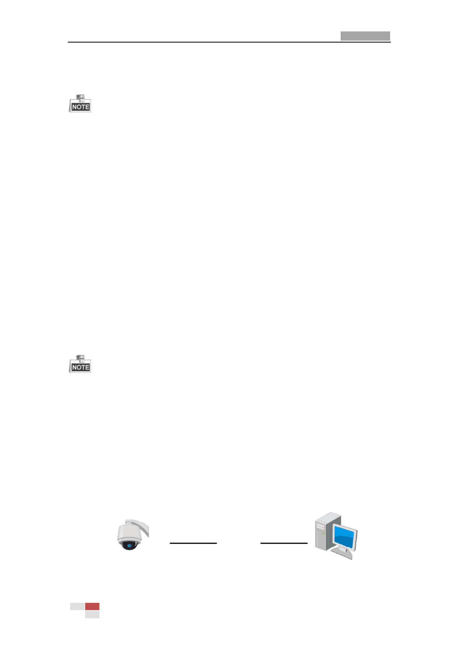
2.1.1 Wiring over the LAN
The following gures show the two ways of cable connecon of network camera and a a
computer:
Purpose:
To test the network camera, you can directly connect the network camera to the computer
with a network cable as shown in Figure 2-1.
Refer to the Figure 2-2 set the network camera over the LAN via a switch or a router. to
Network Cable
Network Speed Dome
Computer
Figure 2-1 Connecng Directly
User Manual of Network PTZ Camera
© Hikvision
5
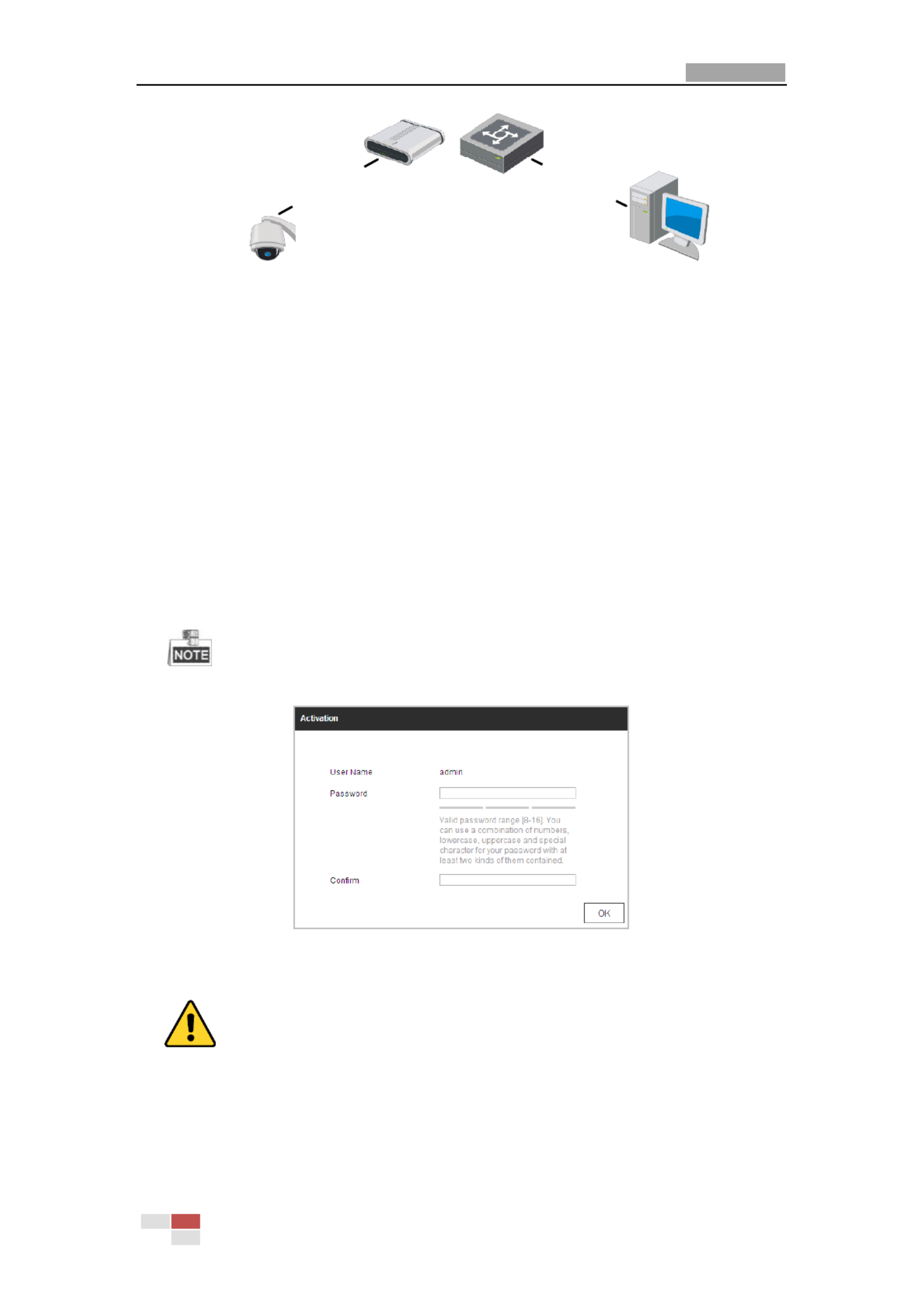
Network Cable
Network Cable
or
Network Speed Dome Computer
Figure 2-2 Connecng via a Switch or Router a
2.1.2 Activang the Camera
Purpose:
You are required to activate the camera rst before you can use the came . ra
Acvaon via web browser, acvation via SADP, and acvation via client soware are supported.
Acvation via Web Browser
Steps:
1. Power on the camera, and connect the camera to the network.
2. Input the IP address into the address bar of the web browser, and click to enter the Enter
acvaon interface.
The default IP address of the camera is 192.168.1.64.
Figure 2-3 Acvaon Interface (Web)
3. Create a password and input the password into the password eld.
For your privacy and to better protect your system against security risks, we strongly
recommend the use of strong passwords for all functions and network devices. The
password should be something of your own choosing (using a minimum of 8 characters,
including upper case letters, lower case letters, numbers and special characters) in order
to increase the security of your product.

User Manual of Network PTZ Camera
© Hikvision
6
Proper configuration of all passwords and other security settings is the responsibility of
the installer and/or end-user.
4. Conrm the password.
5. Click to acvate the camera enter the live view interface. OK and
Acvaon via SADP Soware
SADP soware is used for detecng the online device, acvang the device, and reseng the
password.
Get the SADP soware from the supplied disk or the ofcial website, and install the SADP
according to the prompts. Follow the steps to acvate the camera.
Steps:
1. Run the SADP soware to search the online devices.
2. Check the device status from the device list, and select an inacve device.
Select inacve device.
Input and conrm
password.
Figure 2-4 SADP Interface
The SADP soware supports acvang the camera in batch. Refer to the user manual of
SADP soware for details.
3. Create a password and input the password in the password eld, and conrm the password.
For your privacy and to better protect your system against security risks, we strongly
recommend the use of strong passwords for all functions and network devices. The
password should be something of your own choosing (using a minimum of 8 characters,
including upper case letters, lower case letters, numbers and special characters) in order
to increase the security of your product.
Proper configuration of all passwords and other security settings is the responsibility of
the installer and/or end-user.

User Manual of Network PTZ Camera
© Hikvision
7
You can enable the Hik-Connect service for the device during acvaon. Hik-Connect
funcon varies depending on different speed dome models.
4. Click Acvate start acvaon. You can check whether the acvaon is completed on the to
popup window. If acvaon failed, make sure that the password meets the requirement and
then try again.
5. Change the device IP address to the same subnet with your computer by either modifying
the IP address manually or checking the Enable DHCP checkbox.
Figure 2-5 Modify the IP Address
6. Input the password and click Modify to activate your IP address modicaon.
The batch IP address modicaon is supported by the SADP. Refer to the user manual of
SADP for details.
Acvaon via Client Soware
The client soware is versale video management soware for mulple kinds of devices.
Get the client soware from the supplied disk or the ocial website, and install the soware
according to the prompts. Follow the steps to acvate the camera.
Steps:
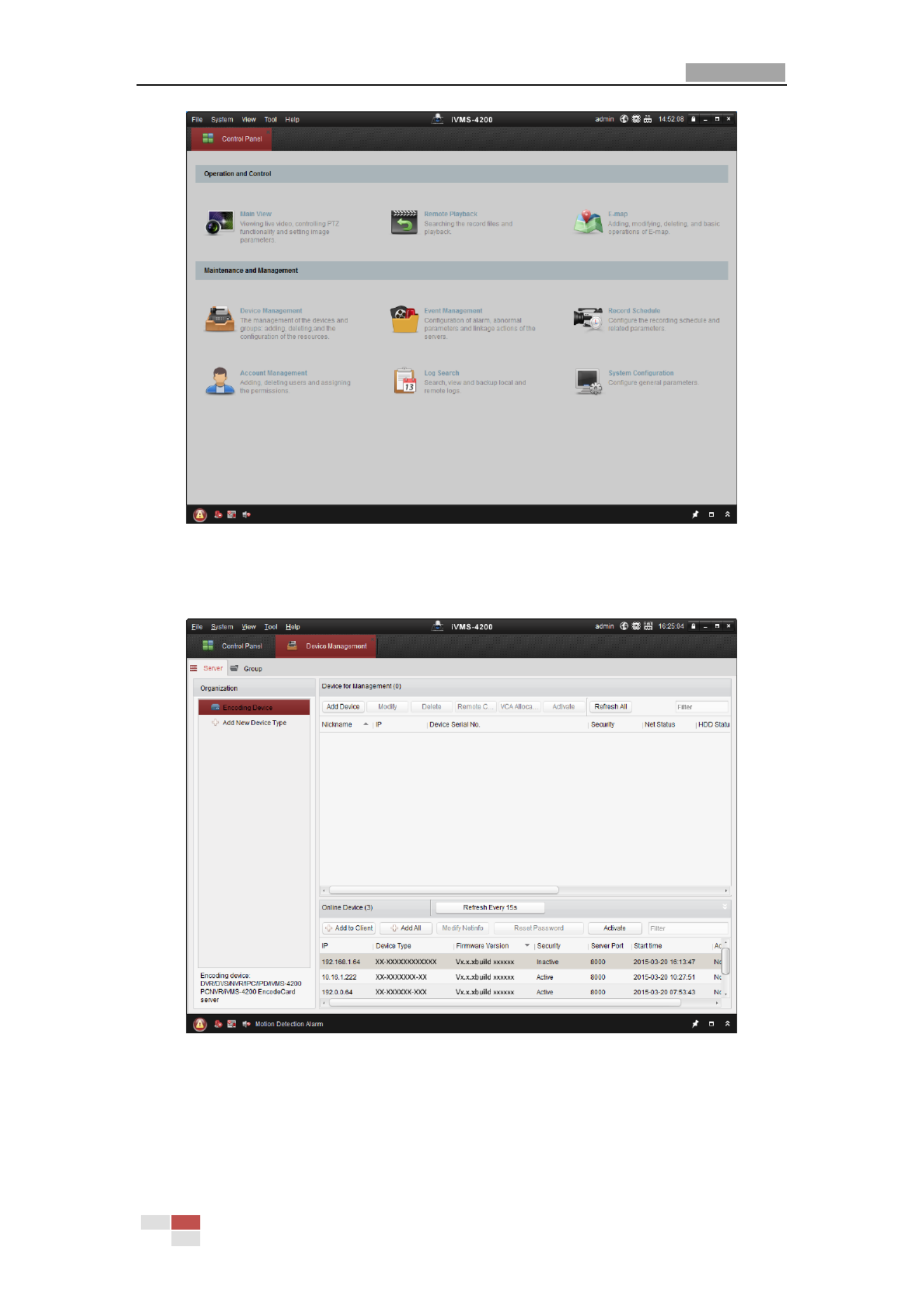
1. Run the client soware and the control panel of the soware pops up, as shown in Figure
2-6.
User Manual of Network PTZ Camera
© Hikvision
8
Figure 2-6 iVMS-4200 Control Panel
2. Click Device Management to enter the Device Management interface, as shown in Figure
2-7.
Figure 2-7 Device Management Interface
3. Check the device status from the device list, and select an inactive device.
4. Click Activate to pop up the Activation interface.
5. Create a password and input the password in the password field, and confirm the password.

User Manual of Network PTZ Camera
© Hikvision
9
For your privacy and to better protect your system against security risks, we strongly
recommend the use of strong passwords for all functions and network devices. The
password should be something of your own choosing (using a minimum of 8 characters,
including upper case letters, lower case letters, numbers and special characters) in order
to increase the security of your product.
Proper configuration of all passwords and other security settings is the responsibility of
the installer and/or end-user.
Figure 2-8 Activation Interface
6. Click to start activation. OK
7. Click Modify Netinfo to pop up the Network Parameter Modification interface, as shown in
Figure 2-9.
Figure 2-9 Modifying the Network Parameters
8. Change the device IP address to the same subnet with your computer by either modifying
the IP address manually or checking the checkbox of Enable DHCP.
9. Input the password to activate your IP address modification.

User Manual of Network PTZ Camera
© Hikvision
10
2.1.3 (Optional) Setting Security Question
Security question is used to reset the admin password when admin user forgets the password.
Admin user can follow the pop-up window to complete security question settings during camera
activation. Or, admin user can go to User Management interface to set up the function.
2.2 Setting the Network Camera over the WAN
Purpose:
This section explains how to connect the network camera to the WAN with a static IP or a
dynamic IP.
2.2.1 Static IP Connection
Before you start:
Apply a static IP from an ISP (Internet Service Provider). With the static IP address, you can
connect the network camera via a router or connect it to the WAN directly.
Connecting the network camera via a router
Steps:
1. Connect the network camera to the router.
2. Assign a LAN IP address, the subnet mask and the gateway. Refer to for detailed Section 2.1.2
IP address configuration of the camera.
3. Save the static IP in the router.
4. Set port mapping, E.g 80, 8000 and 554 ports. The steps for port mapping vary depending .,
on different routers. Call the router manufacturer for assistance with port mapping.
5. Visit the network camera through a web browser or the client software over the internet.
Network
Speed Dome
Network
Cable
Router with Static IP
PC
Network
Cable
Network
Cable
Internet
Figure 2- Accessing the Camera through Router with Static IP 10
Connecting the network camera with static IP directly
You can also save the static IP in the camera directly connect it to the internet without using and
a router. Refer to Section 2.1.2 for detailed IP address configuration of the camera.

User Manual of Network PTZ Camera
© Hikvision
11
Network
Speed Dome
PC
Network
Cable
Network
Cable
Internet
Figure 2- Accessing the Camera with Static IP Directly 11
2.2.2 Dynamic IP Connection
Before you start:
Apply a dynamic IP from an ISP. With the dynamic IP address, you can connect the network
camera a modem or a router. to
Connecting the network camera via a router
Steps:
1. Connect the network camera to the router.
2. In the camera, assign a LAN IP address, the subnet mask and the gateway. Refer to Section
2.1.2 for detailed LAN configuration.
3. In the router, set the PPPoE user name, password and confirm the password.
For your privacy and to better protect your system against security risks, we strongly
recommend the use of strong passwords for all functions and network devices. The
password should be something of your own choosing (using a minimum of 8 characters,
including upper case letters, lower case letters, numbers and special characters) in order
to increase the security of your product.
Proper configuration of all passwords and other security settings is the responsibility of
the installer and/or end-user.
4. Set port mapping. E.g. 80, 8000 and 554 ports. The steps for port mapping vary depending on
different routers. Call the router manufacturer for assistance with port mapping.
5. Apply a domain name from a domain name provider.
6. Configure the DDNS settings in the setting interface of the router.
7. Visit the camera via the applied domain name.
Connecting the network camera via a modem
Purpose:
This camera supports the PPPoE auto dial-up function. The camera gets a public IP address by
ADSL dial-up after the camera is connected to a modem. You need to configure the PPPoE
parameters of the network camera. Refer to Section 6.1.1 Configuring PPPoE Settings for
detailed configuration.

User Manual of Network PTZ Camera
© Hikvision
12
The obtained IP address is dynamically assigned via PPPoE, so the IP address always changes after
rebooting the camera. To solve the inconvenience of the dynamic IP, you need to get a domain
name from the DDNS provider (E.g. DynDns.com). Follow the steps below for normal domain
name resolution and private domain name resolution to solve the problem.
Normal Domain Name Resolution
Steps:
1. Apply a domain name from a domain name provider.
2. Configure the DDNS settings in the interface of the network camera. Refer to DDNS Settings
Section 6.1.1 Configuring DDNS Settings for detailed configuration.
3. Visit the camera via the applied domain name.

User Manual of Network Z Camera PT
© Hikvision
13
Chapter 3 Accessing the Network to
Speed Dome
3.1 Accessing by Web Browsers
Steps:
1. Open the web browser.
2. In the address field, input the IP address of the network camera e.g., 192.168.1.64 and press ,
the key to enter the login interface. Enter
3. Activate the camera for the first time using, refer to the section 2.1.2 Activating the Camera.
4. Select English as the interface language on the top-right of login interface.
5. Input the user name and passwo and click . rd
The admin user should configure the device accounts and user/operator permissions properly.
Delete the unnecessary accounts and user/operator permissions.
The device IP address gets locked if the admin user performs 7 failed password attempts (5
attempts for the user/operator).
Figure 3-1 Login Interface
6. Install the plug-in before viewing the live video and operating the camera Follow the .
installation prompts to install the plug- . in
You may have to close the web browser to install the plug- Reopen the web browser and in.
log in again after installing the plug- in.

User Manual of Network PTZ Camera
© Hikvision
14
Figure 3-2 Download and Install Plug- in
3.2 Accessing by Client Software
The product CD contains the client software. You can view the live video and manage the
camera with the client software.
Follow the installation prompts to install the client software and WinPcap. The configuration
interface and live view interface of client software are shown Figure 3-3. in
Figure 3-3 iVMS- Control Panel 4200

User Manual of Network PTZ Camera
© Hikvision
15
Figure 3-4 iVMS- Live View Interface 4200
If you use third party VMS software, contact technical support of our branch for camera
firmware.
For detailed information about client software of our company, refer to the user manual of
the software. This manual mainly introduces accessing to the network mera by web browser. ca

User Manual of Network Z Camera PT
© Hikvision
16
Chapter 4 Basic Operations
In this and the following chapters, operation of the camera by the web browser will be taken as
an example.
4.1 Configuring Local Parameters
T local configuration refers to the parameters of the live view and other operations using the he
web browser.
Steps:
1. Enter the Local Configuration interface:
Configuration > Local
Figure 4-1 Local Configuration Interface
2. Configure the following settings:
Live View Parameters: Set the protocol type, play performance, rules and image format.
Protocol Type: TCP, UDP, MULTICAST and HTTP are selectable.
TCP: Ensures complete delivery of streaming data and better video quality, yet the
real-time transmission will be affected.
UDP: Provides real-time audio and video streams.
MULTICAST: It’s recommended to select the protocol type to MULTICAST when using
the Multicast function.
HTTP: Allows the same quality as of TCP without setting specific ports for streaming
under some network environments.
Play Performance: Set the play performance to Shortest Delay, Balanced, or Fluent.
Rules: You can enable or disable the rules of dynamic analysis for motion here.

User Manual of Network PTZ Camera
© Hikvision
17
Image Format: The captured pictures can be saved as different format. JPEG and BMP are
available.
Record File Settings: Set the saving path of the video files.
Record File Size: Select the packed size of manually recorded downloaded video filesand .
The size can be set to 256M, 512M or 1G.
Save record files to: Set the saving path for the manually recorded video files.
Save downloaded files to: Set the saving path for the downloaded video files in
interface.
Picture and Clip Settings: Set the saving paths of the captured pictures and clipped video
files.
Save snapshots in live view to: Set the saving path the manually captured pictures in of
interface.
Save snapshots when playback to: Set the saving path the captured pictures in of
interface.
Save clips to: Set the saving path the clipped video files in interface. of
You can click Browse to change the directory for saving video files, clips and pictures.
You can click to directly open the video files, clips and pictures. Open
3. Click to save the settings.
4.2 Live View Page
Purpose:
The live video page allows you to view live video, capture images, realize PTZ control, set/call
presets and configure video parameters.
L the network camera enter the live view page, or you can click on the menu og in to
bar of the main page to enter the live view page.
The functions vary depeding on different camera models. Refer to the actual interface as
standard.

User Manual of Network PTZ Camera
© Hikvision
18
Descriptions of the live view page:
Menu Bar
Live View
Parameters
Live View Window
Toolbar
Show or hide PTZ
control panel
PTZ Control
Preset/Patrol/Pattern
Figure 4-2 Live View Page
Menu Bar:
Click each tab to enter Live View, Playback, Picture, and Configuration page respectively.
Click to display the help file of the network camera.
Click to logout the system.
Live View Window:
Display the live video.
Toolbar:
Operations on the live view page, e.g., live view, capture, record, audio on/off, regional exposure,
regional focus, etc.
PTZ Control:
Panning, tilting, focusing and zooming actions of the network. The lighter, wiper, one-touch focus
and lens initialization control.
Preset/patrol/pattern:
Set and call the preset/patrol/pattern for the camera.
Live View Parameters:
Configure the image size, stream type, plug-in type, and two-way audio of the live video.
4.3 Starting Live View
In the live view window as shown in Figure 4-3, click on the toolbar to start the live view of
the network.

User Manual of Network PTZ Camera
© Hikvision
19
Figure 4-3 Start Live View
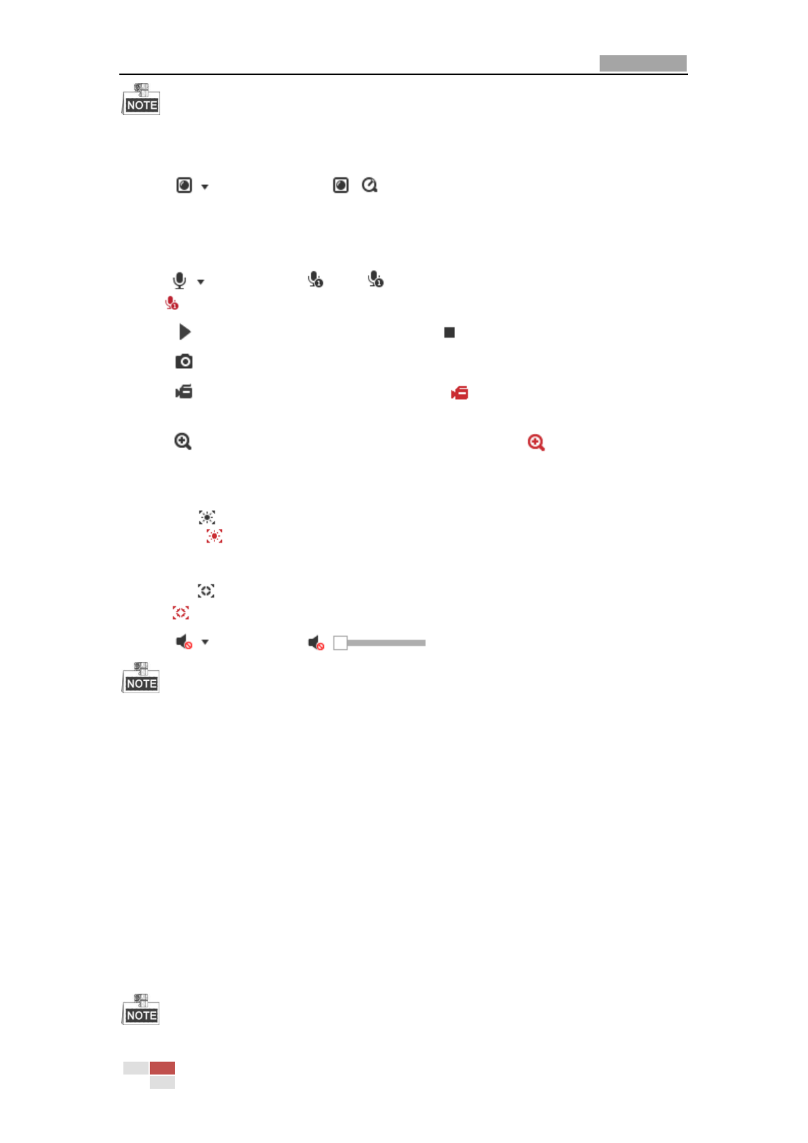
Table 4-1 Descriptions of the Toolbar
Icon
Description
Icon
Description
/
Start/stop Live view.
Manually capture the pictures.
/ /
/
Display in 4:3/16:9/original/
self-adaptive window size.
/ /
Live view with the
main/sub/third stream.
/
Play via webcomponents/
quick time.
/
Start/s t -way audio. top wo
/
Manual start/stop recording.
/
Mute/audio on and adjust
volume
/
Start/stop digital zoom.
/
Enable/disable regional
exposure
/
Enable/disable regional focus
Double-click on the live video to switch the current live view into full-screen or return to
normal mode from the full-screen.
Click to select from and display live video in 4:3/16:9/
original/self-adaptive window size.
Click to select from and display live video with the main/ sub/third
stream. The main stream is with a relatively high resolution and needs much bandwidth. The
default setting of stream type is .
User Manual of Network PTZ Camera
© Hikvision
20
For some certain camera models, disable the third stream first and then the true WDR function is
valid.
Click to select between and play the live video via player Webcomponents
or Quick Time. The live video is played via webcomponents by default, and other types of
players are supported for the browser, such as MJPEG, and VLC. You are required to download
and install the player to play the live video.
Click and it displays . Click to enable two-way audio and the icon turns
into . Click the icon again to stop two-way audio.
Click to start live view and the icon turns into . Click the icon again to stop live view.
Click to capture the picture.
Click to start recording and the icon turns into . Click the icon again to stop
recording.
Click to enable digital zoom function and the icon turns into . Then drag the mouse
towards low right direction to draw a rectangle on the image as the desired zoom. After
viewing it you can click any place of the picture to get back to normal picture.
Click the on the toolbar to enter the regional exposure operation mode and the icon
turns into . Then drag the mouse to draw a rectangle on the image as the desired
exposure region.
Click the the toolbar to enter the regional focus operation mode and the icon turns on
into . Then drag the mouse to draw a rectangle on the image as the desired focus region.
Click to display the . Drag the slider to adjust the volume.
Before using the two-way audio or recording with audio functions, set the Stream Type Video to
& Audio referring to Section 6.2.1 Configuring Video Settings .
Refer to the following sections for more information:
Configuring remote recording in Section 5.1.1 Configuring Recording Schedule.
Setting the image quality of the live video in Section 6.3 Configuring Image Settings and
Section 6.2.1 Configuring Video Settings .
Setting the OSD text on live video in Section 6.3.2 Configuring OSD Settings .
4.4 Operating PTZ Control
Purpose:
In the live view interface, you can use the PTZ control buttons to control pann , tilt ing ing and
zooming.

User Manual of Network PTZ Camera
© Hikvision
21
PTZ functions vary depending on different camera models.
4.4.1 PTZ Control Panel
On the live view page, click to show the PTZ control panel or click to hide it.
Click the direction buttons to control the pan/tilt movements.
Click the zoom/iris/focus buttons to realize lens control.
Figure 4-4 PTZ Control Panel
Table 4-2 Descriptions of PTZ Control Panel
Button
Name
Description
PTZ Control Panel
Hold and press the direction button
to pan/tilt the camera.
Click and the camera keeps
panning, the icon turns into .
Click the icon again to stop the
camera.
Zoom out/ in
Click , the lens zooms in, click
, and the lens zooms out.

User Manual of Network PTZ Camera
© Hikvision
22
Button
Name
Description
Focus near/far
Click , the lens focus far and the
items far away gets clear. Click ,
the lens focus near and the items
nearby gets clear.
Iris close/open
When the image is too dark, click
to open the iris. When the
image is too bright, click to
close the iris.
Auxiliary Functions
The auxiliary functions include light,
wiper, auxiliary focus, lens
initialization, manual tracking, 3D
positioning, one-touch patrol, and
one-touch park.
Speed Adjustment
Adjust speed of pan/tilt movements.
Preset
Refer to for detailed 4.4.3
information of setting preset.
Patrol
Refer to for detailed 4.4.4
information of setting patrol.
Pattern
Refer to for detailed 4.4.6
information of setting pattern.
Buttons on the Preset/Patrol/ tterns interface: Pa
Table 4-3 Descriptions of Buttons
Buttons
Description
Start the selected patrol/pattern.
Stop current patrol/pattern.
Set the selected preset/patrol.
Delete the selected preset/patrol/pattern.
Start recording a pattern.
Stop recording the pattern.
4.4.2 Auxiliary Functions
The Auxiliary functions panel is shown in Figure 4-5.

User Manual of Network PTZ Camera
© Hikvision
23
Figure 4-5 Auxiliary Functions
Light
Click to enable/disable the light supplement of the camera. This function is reserved.
Wiper
Click to move the wiper once.
Auxiliary Focus
The auxiliary focus function is reserved.
Manual Tracking
Before you start:
Enter the Smart Tracking settings interface and enable smart tracking first.
Configuration > PTZ > Smart Tracking
Steps:
1. Click on the toolbar of live view interface.
2. Click a moving object in the live video.
The camera will track the object automatically.
3D Positioning
Steps:
1. Click on the toolbar of live view interface.
2. Operate the 3D positioning function:
Click a position of the live video. The corresponding position will be moved to the center of
the live video.
Hold down the left mouse button and drag the mouse to the lower right on the live video.
The corresponding position will be moved to the center of the live video and zoomed in.
Hold down the left mouse button and drag the mouse to the upper left on the live video.
The corresponding position will be moved to the center of the live video and zoomed out.
One-touch Patrol
Click to call one-touch patrol. For detailed information of setting one-touch patrol,
refer to 4.4.5 One-touch Patrol.
One-touch Park
Click to save the current view as the preset No. 32 and start park at the the current
position.

User Manual of Network PTZ Camera
© Hikvision
24
4.4.3 Setting/Calling a Preset
Purpose:
A preset is a predefined image position. For the defined preset, you can click the calling button to
quickly view the desired image position.
Setting a Preset:
Steps:
1. In the PTZ control panel, select a preset number from the preset list.
Figure 4-6 Setting a Preset
2. Use the PTZ control buttons to move the lens the desired position. to
• Pan the camera to the right or left.
• Tilt the camera up or down.
• Zoom in or out.
• Refocus the lens.
3. Click to finish the setting of the current preset.
4. Edit a preset name by double clicking on the default name such as preset 1. (The pre-defined
presets are named already and not configurable. Refer to the user manual for detailed
function description.)
5. You can click delete the preset. to
You can configure up to presets. 256
Calling a Preset:
In the PTZ control panel, select a defined preset from the list and click to call the preset.
Figure 4-7 Calling a Preset
For convenient preset selection, refer to the following steps to navigate to the preset you want.

User Manual of Network PTZ Camera
© Hikvision
25
Steps:
1. Select any preset from the list.
2. Click the preset number you need on the keyboard.
The following presets are predefined with special commands. You can only call them but not
configure them. For instance, preset 99 is the auto “Start scan”. If you call the preset 99, the
camera starts auto scan function.
Pattern function varies depending on different camera models .
Table 4-4 Special Presets
Preset
Function
Preset
Function
33
Auto flip
92
Start to set limit stops
34
Back to initial position
93
Set limit stops manually
35
Call patrol 1
94
Remote reboot
36
Call patrol 2
95
Call OSD menu
37
Call patrol 3
96
Stop a scan
38
Call patrol 4
97
Start random scan
39
Day mode (IR cut filter in)
98
Start frame scan
40
Night mode (IR cut filter out)
99
Start auto scan
41
Call pattern 1
100
Start tilt scan
42
Call pattern 2
101
Start panorama scan
43
Call pattern 3
102
Call patrol 5
44
Call pattern 4
103
Call patrol 6
45
One-touch Patrol
104
Call patrol 7
90
Wiper
105
Call patrol 8
Figure 4-8 Special Preset
You may need to use the OSD (On Screen Display) menu when controlling the camera
remotely. To display the OSD menu on the live view screen, you can call the preset number
95.
User Manual of Network PTZ Camera
© Hikvision
26
4.4.4 Setting/Calling a Patrol
Purpose:
A patrol is a memorized series of preset function. It can be configured and called on the patrol
settings interface. There are up to 8 patrols for customizing. A patrol can be configured with 32
presets.
Before you start:
Make sure that the presets you want to add into a patrol have been defined.
Setting a Patrol:
Steps:
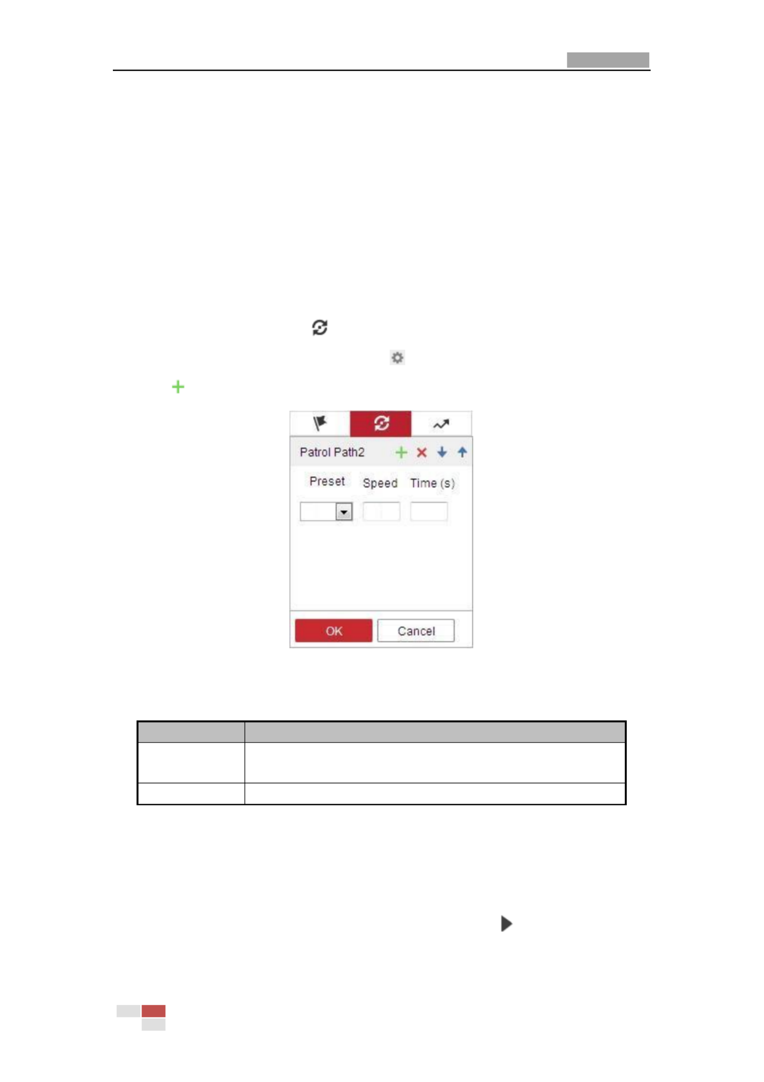
1. In the PTZ control panel, click to enter the patrol settings interface.
2. Select a patrol number from the list and click .
3. Click to enter the adding interface of preset, as shown in Figure 4-9.
Figure 4-9 Adding Presets
4. Configure the preset number, patrol time and patrol speed.
Name
Description
Patrol Time
It is the duration staying on one patrol point. The camera moves to
another patrol point after the patrol time.
Patrol Speed
It is the speed of moving from one preset to another.
5. Click to save a preset into the patrol. OK
6. Repeat the steps from 3 to 5 to add more presets.
7. Click to save all the patrol settings. OK
Calling a Patrol:
In the PTZ control panel, select a defined patrol from the list and click to call the patrol, as
shown in Figure 4- . 10

User Manual of Network PTZ Camera
© Hikvision
27
Figure 4- Calling a Preset 10
4.4.5 One-touch Patrol
Purpose:
One-touch patrol is an automatically created patrol. The system automatically add preset No.1 to
No.32 to the patrol path 8. You can call the one-touch patrol and the camera moves as the patrol
path 8 automatically.
Steps:
1. Set preset No.1 to No.32. Refer to 4.4.3 Setting/Calling a Preset for detailed information of
setting preset.
2. Call preset No. 45, and the camera moves as patrol path 8.
3. C to enter the patrol settings interface and start/stop one-touch patrol, edit the lick
patrol time and the speed.
4. You can click of the PTZ control panel to start one-touch patrol.
Figure 4- Patrol Path 8 11

User Manual of Network PTZ Camera
© Hikvision
28
4.4.6 Setting/Calling a Pattern
Purpose:
A pattern is a memorized series of pan, tilt, zoom, and preset functions. It can be called on the
pattern settings interface. There are up to 4 tterns for customizing. pa
Pattern function varies depending on different camera models.
Setting a Pattern:
Steps:
1. In the PTZ control panel, click to enter the pattern settings interface.
2. Select a pattern number from the list as shown in Figure 4- . 12
Figure 4- Patterns Settings Interface 12
3. Click to enable recording the panning, tilting and zooming actions.
4. Use the PTZ control buttons to move the lens the desired position after the information of to
PROGRAM PATTERN REMAINNING MEMORY(%) is displayed on the screen.
Pan the camera to the right or left.
Tilt the camera up or down.
Zoom in or out.
Refocus the lens.
5. Click to save all the pattern settings.
Buttons on the Patterns interface:
Buttons
Description
Start the selected patrol/pattern.
Stop current patrol/pattern.
Set the selected preset/patrol.
Delete the selected preset/patrol/pattern.
Start recording a pattern.
Stop recording the pattern.
User Manual of Network PTZ Camera
© Hikvision
29
These 4 patterns can be operated separately and with no priority level.
When configuring and calling the pattern, proportional pan is valid; the limit stops and auto
flip will be invalid; and the 3D positioning operation is not supported.
4.5 Playback
Purpose:
This section explains how to view the video files stored in the network disks or memory cards.
4.5.1 Play Back Video Files
Steps:
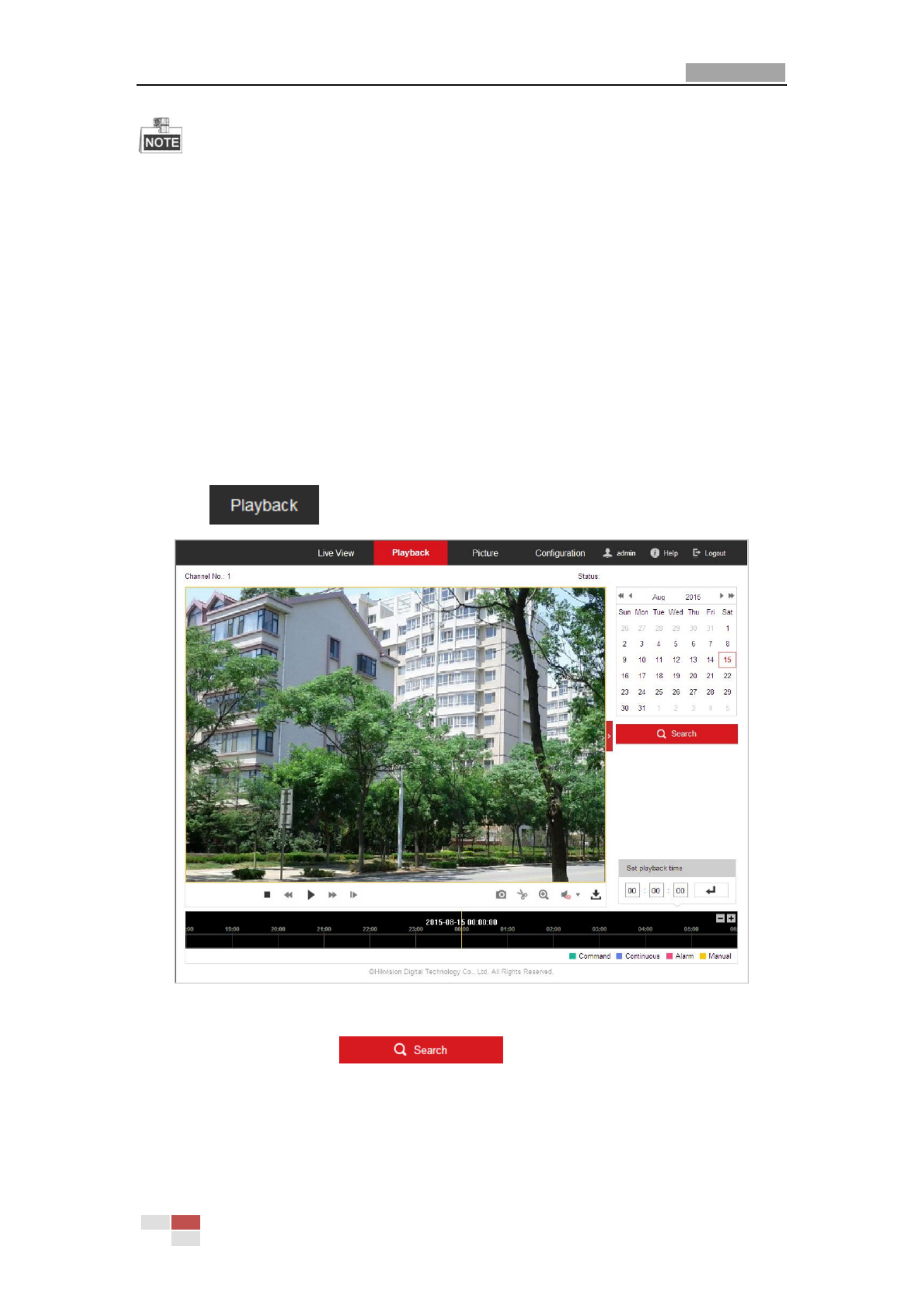
1. Click on the menu bar to enter playback interface.
Figure 4- Playback Interface 13
2. Select the date and click .

User Manual of Network PTZ Camera
© Hikvision
30
Figure 4- Search Video 14
3. Click to play the video files found on this date.
The toolbar the bottom of Playback interface can be used to control playing process. on
Figure 4- Playback Toolbar 15
Table 4-5 Description of the buttons
Button
Operation
Button
Operation
Play
Capture a picture
Pause
/
Start/Stop clipping
video files
Stop
/
Audio on and adjust
volume/Mute
Speed down
Download
Speed up
Playback by frame
/
Enable/Disable
digital zoom
You can choose the file paths locally for downloaded playback video files and pictures in Local
Configuration interface. Refer to Section 4.1 Configuring Local Parameters for details.
Drag the progress bar with the mouse to locate the exact playback point. You can also input the
time and click to locate the playback point in the Set playback time field. You can also
click to zoom out/in the progress bar.
Figure 4- Set Playback Time 16

User Manual of Network PTZ Camera
© Hikvision
31
Figure 4- Progress Bar 17
The different colors of the video on the progress bar stand for the different video types as shown
in Figure 4- . 18
Figure 4- Video Types 18
4.5.2 Downloading Video Files
Steps:
1. Click on the playback interface. The pop-up menu is shown in Figure 4-19.
2. Set the start time and end time. Click Search. The corresponding video files are listed on the
left.
Figure 4- Video Downloading interface 19
3. Check the checkbox in front of the video files that you need to download.
4. Click to download the video files.
4.6 Pictures
Purpose:
This section explains how to view the captured picture files stored in the network disks or the
User Manual of Network PTZ Camera
© Hikvision
32
memory cards and download the captured pictures.
Steps:
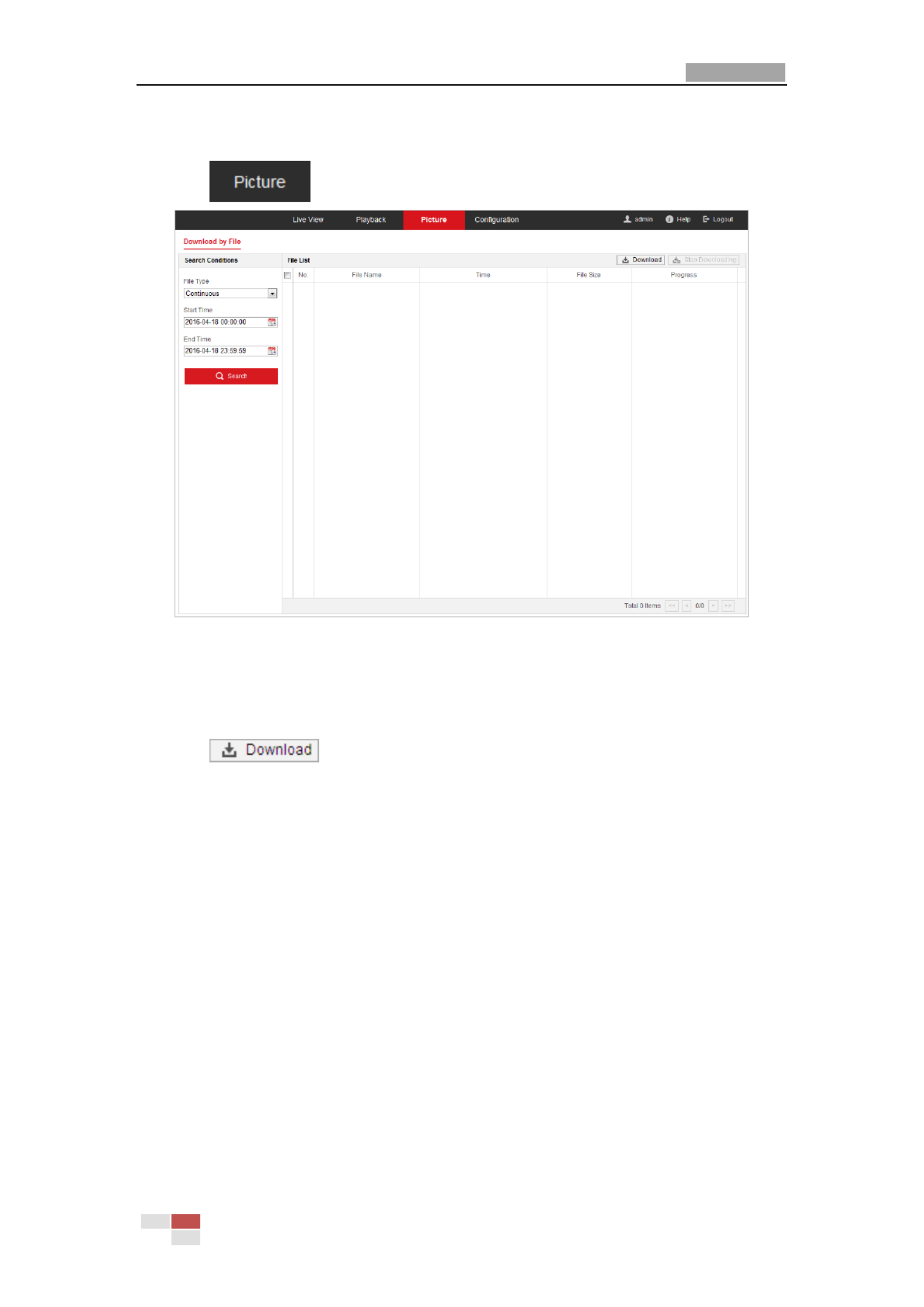
1. Click on the menu bar to enter picture interface.
Figure 4- Picture Interface 20
2. Select the file type of capturing the pictures from the list as timing, alarm, motion, etc.
3. Set the start time and end time. Click Search. The corresponding picture files will be listed.
4. Check the checkbox in front of the files that you need to download.
5. Click to download the files.
User Manual of Network Z Camera PT
© Hikvision
33
Chapter 5 System Configuration
5.1 Storage Settings
Before you start:
To configure record settings, make sure that you have the network storage device within the
network or the memory card inserted in your camera.
5.1.1 Configuring Recording Schedule
Purpose:
There are two kinds of recording for the camera: manual recording and scheduled recording. In
this section, you can follow the instructions to configure the scheduled recording. By default, the
record files scheduled recording are stored in the memory card (if supported) or the of in
network disk.
Steps:
1. Enter the Record Schedule settings interface:
Configuration Storage > Schedule Settings > Record Schedule>
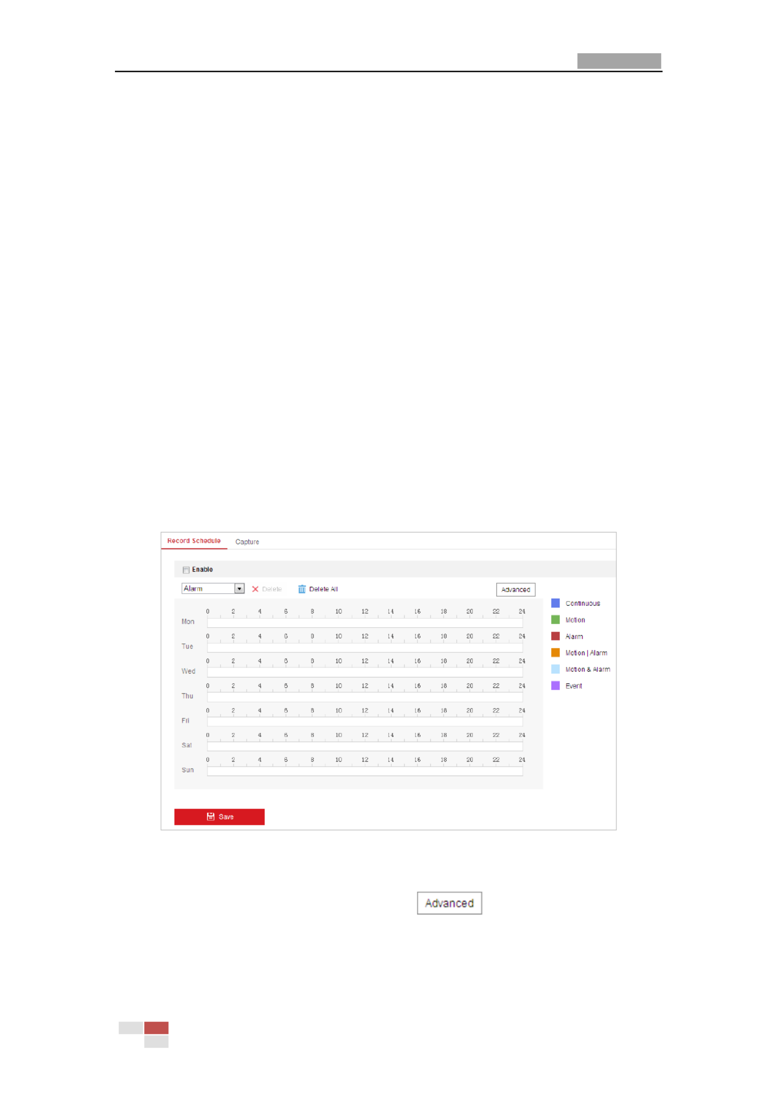
Figure 5-1 Record Schedule Interface ing
2. Check the checkbox of Enable to enable scheduled recording.
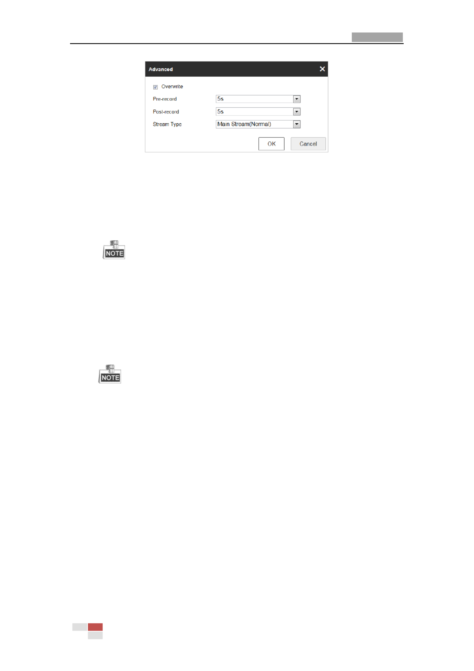
3. To set the advanced settings of the camera, click to enter the advanced settings
interface.
User Manual of Network PTZ Camera
© Hikvision
34
Figure 5-2 Record Parameters
Pre-record: The time you set to start record before the scheduled time or the event. ing
For example, an alarm triggers recording at 10:00, and the pre-record time is set as 5 if
seconds, the camera starts to record at 9:59:55.
The p -record time can be configured as No Pre-record, 5 s, 10 s, 15 s, 20 s, 25 s, 30 s or re
not limited.
The pre-record time changes according to the video bitrate.
Post-record: The time you set to stop recording after the scheduled time or the event.
For example, an alarm triggerif ed recording ends at 11:00, the post-record time is and
set as 5 seconds, the camera records til 11:00:05. un
The Post-record time can be configured as 5 s, 10 s, 30 s, 1 min, 2 min, 5 min or 10 min.
Stream Type: You can select the stream type for recording; Main Stream, Sub-Stream
and Third Stream are selectable. If you select the sub-stream, you can record for a longer
time with the same storage capacity.
The Pre-record and Post-record parameters vary depending on different camera models.
4. Click to save the advanced setting. OK
5. Select a Record Type. The record type can be Continuous, Motion, Alarm, Motion | Alarm,
Motion & Alarm, and Event.
Normal: If you select Continuous, the video will be recorded automatically according to
the time of the schedule.
Record Triggered by Motion Detection: If you select Motion, the video will be recorded
when the motion is detected. Besides configuring the recording schedule, you have to
set the motion detection area and check the checkbox of Trigger Channel in the Linkage
Method of Motion Detection settings interface. For detailed information, refer to
Section Motion Detection.
Record Triggered by Alarm: If you select Alarm, the video will be recorded when the
alarm is triggered via the external alarm input channels. Besides configuring the
recording schedule, you have to set the Alarm Type and check the checkbox of Trigger
Channel in the Linkage Method of Alarm Input settings interface. For detailed
information, refer to Section Alarm Input.
Record Triggered by Motion & Alarm: If you select Motion & Alarm, the video will be
recorded when the motion and alarm are triggered at the same time. Besides

User Manual of Network PTZ Camera
© Hikvision
35
configuring the recording schedule, you have to configure the settings on the Motion
Detection and Alarm Input settings interfaces.
Record Triggered by Motion | Alarm: If you select Motion | Alarm, the video will be
recorded when the external alarm is triggered or the motion is detected. Besides
configuring the recording schedule, you have to configure the settings on the Motion
Detection and Alarm Input settings interfaces.
Record Triggered by Event: If you select to record by event, the video will be recorded
when any of the events is triggered.
6. Click to save the settings.
5.1.2 Configuring Capture Schedule
Purpose:
You can configure the scheduled snapshot and event-triggered snapshot. The captured picture
can be stored in the local storage or network storage.
Steps:
1. Enter the Snapshot settings interface:
Configuration > Storage Storage Settings Capture > >
Figure 5-3 Snapshot Settings
2. Click to enter the Capture Schedule interface.
3. Select the timeline of a certain day, drag the left button of the mouse to set the capture and
schedule (the start time and end time of the recording task).
4. After you set the schedule task, you can click and copy the task to other days d
(optional).
5. After setting the capture schedule, you can click a capture segment to display the segment
capture settings interface to edit the segment capture parameters. (optional)

User Manual of Network PTZ Camera
© Hikvision
36
Figure 5-4 Segment Snapshot ttings Se
6. Click to enter the advanced setting interface. You can select the stream type of
the capture.
7. Click to enter the Capture Parameters Interface.
8. Check the Enable Timing Snapshot checkbox to enable continuous snapshot, and configure
the schedule of timing snapshot. Check the Enable Event-triggered Snapshot checkbox to
enable event-triggered snapshot.
9. Select the format, resolution, quality of the snapshot.
10. Set the time interval between two snapshots.
11. Click to save the settings.
Uploading to FTP
Make sure that the FTP server is online.
You can follow below configuration instructions to upload the snapshots to FTP.
Upload continuous snapshots to FTP
Steps:
1) Configure the FTP settings and check Upload Picture checkbox in FTP Settings interface.
Refer to Section 6.1.2 Configuring FTP Settings for more details to configure FTP parameters.
2) Check the Enable Timing Snapshot checkbox.
3) Click to set the snapshot schedule Refer to Edit . Section 5.2.1 nfiguring Motion Co
Detection.
Upload event-triggered snapshots to FTP
Steps:
1) Configure the FTP settings and check Upload Picture checkbox in FTP Settings interface.
Refer to Section 6.1.2 Configuring FTP Settings for more details to configure FTP parameters.
2) Check Upload to FTP checkbox in Motion Detection Settings or Alarm Input interface. Refer
to Section 5.2.1 nfiguring Motion DetectionCo .
3) Check the Enable Event-triggered Snapshot checkbox.
5.1.3 Configuring Net HDD
Before you start:
User Manual of Network PTZ Camera
© Hikvision
37
The network disk should be available within the network and properly configured to store the
recorded files, log files, etc.
Steps:
Add the network disk
1. Enter the NAS (Network-Attached Storage) settings interface:
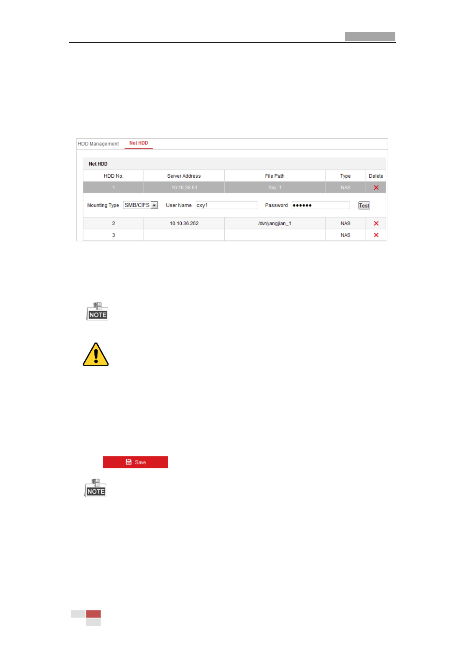
Configuration > Storage > Storage Management > Net HDD
Figure 5-5 Select Net HDD Type
2. Enter the IP address and the file path of the network disk.
3. Select the mounting type. NFS and SMB/CIFS are selectable. You can set the user name and
password to guarantee the security if SMB/CIFS is selected.
Refer to the NAS User Manual for creating the file path.
For your privacy and to better protect your system against security risks, we strongly
recommend the use of strong passwords for all functions and network devices. The
password should be something of your own choosing (using a minimum of 8 characters,
including upper case letters, lower case letters, numbers and special characters) in order
to increase the security of your product.
Proper configuration of all passwords and other security settings is the responsibility of
the installer and/or end-user.
4. Click to add the network disk.
After having saved successfully, you need to reboot the camera to activate the settings.
Initialize the added network disk.
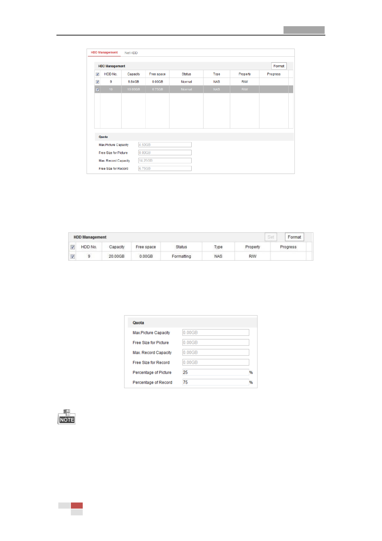
1. Enter the HDD settings interface (Configuration > Storage > Storage Management > HDD
Management) in which you can view the capacity, free space, status, type and property of ,
the disk.
User Manual of Network PTZ Camera
© Hikvision
38
Figure 5-6 Storage Management Interface
2. If the status of the disk is Uninitialized, check the corresponding checkbox to select the disk
and click Format to start initializing the disk.
3. When the initialization completed, the status of disk will become as shown in Figure Normal
5-7 .
Figure 5-7 View Disk Status
Define the Quota for Record and Pictures
1. Input the quota percentage for picture and for record.
2. Click Save and refresh the browser page to activate the settings.
Figure 5-8 Quota Settings
Up to 8 NAS disks can be connected to the camera.
To initialize and use the memory card after insert it to the camera, refer to the steps of NAS
disk initialization

User Manual of Network PTZ Camera
© Hikvision
39
5.2 Basic Event Configuration
Purpose:
This section explains how to configure the network camera to respond to alarm events, including
motion detection, video tampering alarm input, alarm output and exception. These events can
trigger the alarm actions, such as Send Email, Notify Surveillance Center, etc.
For example, when motion detection is triggered, the network camera sends a notification to an
e-mail address.
On the event configuration page, click to show the PTZ control panel or click hide it. to
Click the direction buttons to control the pan/tilt movements.
Click the zoom/iris/focus buttons to realize lens control.
The functions vary depending on different camera models.
5.2.1 Configuring Motion Detection
Purpose:
Motion detection is a feature which can trigger alarm actions actions of recording videos and
when the motion occurr in the surveillance scene. ed
Steps:
1. Enter the motion detection setting interface:
Configuration > Event Basic Event Motion Detection > >
2. Check the checkbox of the Enable Motion Detection to enable this function.
You can check the Enable Motion Detection in PTZ Control checkbox and when the speed
dome is performing PTZ action, motion detection can also trigger alarm.
You can check the Enable Dynamic Analysis for Motion checkbox if you want the detected
object get marked with rectangle in the live view.
3. Select the configuration mode as or and set the corresponding motion Normal Expert
detection parameters.
Normal

User Manual of Network PTZ Camera
© Hikvision
40
Figure 5-9 Motion Detection Settings-Normal
Steps:
(1) Click and drag the mouse the live video image draw motion on to a
detection area.
(2) Click to finish drawing.
You can click to clear all of the areas.
(3) Move the slide to set the r
sensitivity of the detection.
Expert

User Manual of Network PTZ Camera
© Hikvision
41
Figure 5- Motion Detection Settings-Expert 10
Steps:
(1) Set the Schedule Image Settings, there are , OFF Auto-Switch Scheduled-Switchand
selectable. If the schedule image switch mode is enabled, you can configure the
detection rule for the day and night separately.
OFF: Disable the day and night switch.
Auto-Switch: Switch the day and night mode according to the illumination
automatically.
Scheduled-Switch: Switch to the day mode and the night mode according to the
configured time. You need to set the start time and end time.
(2) Select Area from the dropdown list to configure.
(3) Set the values of sensitivity and percentage.
Sensitivity: The greater the value is, the easier the alarm will be triggered.
Percentage: When the size proportion of the moving object exceeds the predefined
value, the alarm will be triggered. The less the value is, the easier the alarm will be
triggered.
4. Set the Arming Schedule for Motion Detection.
(1) Click tab to enter the arming schedule setting interface.

User Manual of Network PTZ Camera
© Hikvision
42
Figure 5- Arming Schedule 11
(2) Select the timeline of a certain day, drag the mouse to set the arming schedule (the and
start time and end time of the arming task).
(3) After you set the scheduled task, you can click copy the task to other days and
(optional).
Figure 5- Arming Time Schedule 12
(4) After setting the arming schedule, you can click a segment to display the segment
arm settings interface to edit the segment record parameters (optional). ing
Figure 5- Segment Arming Settings 13

User Manual of Network PTZ Camera
© Hikvision
43
(5) Click to save the settings.
The time of each period cannot be overlapped. Up to 8 periods can be configured for each
day.
5. Set the Alarm Actions for Motion Detection.
Click tab to enter the Linkage Method interface.
You can specify the linkage method when an event occurs. The following contents are about
how to configure the different types of linkage method.
Figure 5- Linkage Method 14
Check the checkbox to select the linkage method. Notify Surveillance Center, Send
Email, Upload to FTP/Memory/NAS, Trigger Alarm Output and Trigger Recording are
selectable.
Notify Surveillance Center
Send an exception or alarm signal to remote management software when an event
occur s.
Send Email
Send an email with alarm information to a user or users when an event occurs.
To send the Email when an event occurs, you need to refer to Section Configuring Email
Settings to set the Email parameters.
Upload to FTP/Memory/NAS

User Manual of Network PTZ Camera
© Hikvision
44
Capture the image when an alarm is triggered and upload the picture to a FTP server.
You need a FTP server and set FTP parameters first. Refer to Section Configuring FTP
Settings for setting FTP parameters.
Trigger Alarm Output
Trigger one or more external alarm outputs when an event occurs.
To trigger alarm output when an event occurs, refer to an Section 5.2.4 Configuring
Alarm Output to set the alarm output parameters.
Trigger Recording
Record a video when an event occurs.
You have to set the recording schedule to realize this function. fer toRe Section 5.1.1
Configuring Recording Schedule for settings the recording schedule.
5.2.2 Configuring Video Tampering Alarm
Purpose:
You can configure the camera to trigger the alarm actions when the lens is covered.
Steps:
1. Enter the Video Tampering settings interface :
Configuration Event Basic Event Video Tampering > > >

User Manual of Network PTZ Camera
© Hikvision
45
Figure 5- Tamper Alarm 15 ing
2. Check checkbox to enable the tamper detection. Enable ing
3. Click tab to enter the arming schedule setting interface. The arming
schedule configuration is the same the setting of the arming schedule for motion detection. as
Refer to Section 5.2.1 Configuring Motion Detection .
4. Click tab to select the linkage method taken for tamper , notify ing
surveillance center, send email and trigger alarm output are selectable. Refer to Section 5.2.1
Configuring Motion Detection.
5. Click to save the settings.
5.2.3 Configuring Alarm Input
Steps:
1. Enter the Alarm settings interface: Input
Configuration > Event Basic Event > Alarm Input>
2. Choose the Alarm Input No. and the Alarm Type. The alarm type can be NO (Normally Open)
and NC (Normally Closed).
3. Edit the name in to set a name for the
alarm input (optional).

User Manual of Network PTZ Camera
© Hikvision
46
Figure 5- Alarm Input Settings 16
4. Click tab to enter the arming schedule setting interface. The arming
schedule configuration is the same the setting of the arming schedule for motion detection. as
Refer to Section 5.2.1 Configuring Motion Detection.
5. Click tab to select the linkage method taken for alarm , input including
Notify Surveillance Center, Send Email, Upload to FTP/Memory Card/NAS, Trigger Alarm
Output and Trigger Recording Refer to . Section 5.2.1 Configuring Motion Detection .
6. You can also choose the PTZ linking for the alarm input. Check the relative checkbox and
select the No. to enable Preset Calling, Patrol Calling Pattern Calling. or
7. You can copy your settings to other alarm inputs.
8. Click to save the settings.
Figure 5- Linkage Method 17

User Manual of Network PTZ Camera
© Hikvision
47
5.2.4 Configuring Alarm Output
Steps:
1. Enter the Alarm Output settings interface:
Configuration> Event > Basic Event > Alarm Output
2. Select one alarm output channel in the Alarm Output dropdown list.
3. Set a name in for the alarm output
(optional).
4. The Delay time can be set to , , 5sec, 10sec 30sec 1min 2min, , 5min, 10min Manual or . The
delay time refers to the time duration that the alarm output remains in effect after alarm
occurs.
5. Click tab to enter the arming schedule setting interface. The time
schedule configuration is the same the setting of the arming schedule for motion as s
detection Refer to. Section 5.2.1 Configuring Motion Detection.
Figure 5- Alarm Output Settings 18
6. You can copy the settings to other alarm outputs.
7. Click to save the settings.

User Manual of Network PTZ Camera
© Hikvision
48
5.2.5 Handling Exception
The exception type can be HDD full, HDD error, network disconnect , IP address conflict and ed ed
illegal login to the cameras.
Steps:
1. Enter the Exception settings interface:
Configuration > Event Basic Event > Exception>
2. Check the checkbox to set the actions taken for the Exception alarm. Refer to Section 5.2.1
Configuring Motion Detection.
Figure 5- Exception Settings 19
3. Click to save the settings.
5.3 Smart Event Configuration
The functions vary depending on different camera models.

User Manual of Network PTZ Camera
© Hikvision
49
5.3.1 Detecting Audio Exception
Purpose:
When you enable this function and audio exception occurs, the alarm actions will be triggered.
Steps:
1. Enter the video audio exception detection interface:
Configuration Event Smart Event Audio Exception Detection> > >
Figure 5- Audio Exception Detection 20
2. Check the checkbox of Audio Loss Detection to enable the audio input exception detection.
3. Check the checkbox of Sudden Increase of Sound Intensity Detection checkbox to enable
the sudden rise detection.
Sensitivity: Range [1-100], the smaller the value the more severe the sound change will
trigger the detection.
Sound Intensity Threshold : Range [1-100], it can filter the sound in the environment, the
louder the environment sound, the higher the value should be. You can adjust it according
to the actual environment.
4. Check the checkbox of Sudden Decrease of Sound Intensity Detection checkbox to enable
the sudden drop detection.
Sensitivity: Range [1-100], the smaller the value the more severe the sound change will
trigger the detection.
5. Click tab to enter the arming schedule setting interface. The time
schedule configuration is the same the setting of the arming schedule for motion as s

User Manual of Network PTZ Camera
© Hikvision
50
detection. Refer to Section 5.2.1 Configuring Motion Detection .
6. Click tab to select the linkage method taken for the audio input exception,
Notify Surveillance Center, Send Email, Trigger Alarm Output and Trigger Recording are
selectable. Refer to Section 5.2.1 Configuring Motion Detection .
7. Click to save the settings.
5.3.2 nfiguring Face Detection Co
Purpose:
After the face detection is enabled, a face appears in the surveillance area, it will be detected and
certain actions may be triggered by the detection.
Steps:
1. Check the Enable Face Detection checkbox.
2. (Optional) You can check the Enable Dynamic Analysis for Face Detection checkbox if you
want the detected face get marked with rectangle in the live view.
Figure 5- Configuring Face Detection 21
3. Configure the sensitivity for face detection.
Sensitivity: Range [1-5]. The value of the sensitivity defines the size of the object which can
trigger the alarm, when the sensitivity is high, a very small object can trigger the alarm.
4. Click tab to enter the arming schedule setting interface. The time
schedule configuration is the same the setting of the arming schedule for motion as s
detection Refer to . Section 5.2.1 Configuring Motion Detection .
5. Click tab to select the linkage method taken for the video loss alarm, Notify
surveillance center, send email, upload to FTP, trigger channel, smart tracking and trigger
alarm output are selectable. Refer to Section 5.2.1 Configuring Motion Detection .
6. Click to save the settings.
5.3.3 Configuring Intrusion Detection
Intrusion detection can set an area in the surveillance scene and once the area is entered, a set
of alarm action is triggered.
Steps:
1. Enter the intrusion detection interfa :ce
Configuration Events > > Smart Event >Intrusion Detection

User Manual of Network PTZ Camera
© Hikvision
51
2. Check the Enable checkbox.
Figure 5- Configuring Intrusion Area 22
3. The event triggered and park action related PTZ movement will be locked for 180 seconds
after you enter the intrusion detection interface. Optionally, you can click the
button to manually activate the movement, or lock the movement
when the button turns to by clicking it.
4. Draw area.
1) Select the Region No.in dropdown list.
2) Click draw a rectangle on the image as a defense region. to
3) C on the image to specify a corner of the rectangle, and right-click the mouse after lick
four corners are configured.
5. Configure the parameters for each defense region separately.
Threshold: Range [0-10s], the threshold for the time of the object loitering in the region. If
you set the value as 0, alarm is triggered immediately after the object entering the region.
Sensitivity: Range [1-100]. The value of the sensitivity defines the size of the object which
can trigger the alarm, when the sensitivity is high, a very small object can trigger the
alarm.
6. Click tab to enter the arming schedule setting interface. The time

User Manual of Network PTZ Camera
© Hikvision
53
5. Draw area.
1) Click draw a line the image. to on
2) Click the line to switch to the eding mode.
Drag an end to the desired place to adjust the length and angle of the line. And drag the
line to adjust the locaon.
6. Congure the parameters for each defense region separately.
Direction: Select the detecon direcon in the dropdown list, there are A<->B, A->B and
B->A selectable.
Sensitivity: Range [1-100]. The value of the sensivity denes the size of the object which
can trigger the alarm, when the sensivity is high, a very small object can trigger the
alarm.
7. Click tab to enter the arming schedule setng interface. The me
schedule conguraon is the same the setng of the arming s edule for motion as s ch
detecon. Refer to Section 5.2.1 Configuring Motion Detection .
8. Click tab to select the linkage method taken for the line crossing detecon,
Nofy Surveillance Center, Send Email, Upload to FTP/Memory Card/NAS, Trigger Alarm
Output and Trigger Recording e selectable. Refer to ar Section 5.2.1 Configuring Motion
Detection.
9. Click to save the sengs.
5.3.5 Configuring Region Entrance Detection
Purpose:
Region entrance detecon funcon detects people, vehicle or other objects which enter a
pre-dened virtual region from the outside place, and some certain acons can be taken when
the alarm is triggered.
Steps:
1. Enter the Region Entrance Detection sengs interface:
Configuration> Event > Smart Event> Region Entrance Detection
2. Check the checkbox of to enable the Region Entrance Detecon funcon. Enable

User Manual of Network PTZ Camera
© Hikvision
54
Figure 5- Configuring Region Entrance Detection 24
3. Select the region from the dropdown list for detection settings.
4. Click the button to start the region drawing.
5. Click on the live video to specify the four vertexes of the detection region, and right click to
complete drawing.
Repeat the step to configure other regions. You can click the button to clear all
pre-defined regions.
6. Set th etection target for the region entrance detection. You can select human, vehicle, or e d
all (human &vehicle) as the detection target from the dropdown list. If Human is selected,
only human beings will be identified as detection objects and as well as Vehicle.
7. Click tab to enter the arming schedule setting interface. The time
schedule configuration is the same the setting of the arming schedule for motion as s
detection Refer to . Section 5.2.1 Configuring Motion Detection .
8. Click tab to select the linkage method taken for the video loss alarm,
Notify surveillance center, send email, upload to FTP, trigger channel, smart tracking and
trigger alarm output are selectable. Refer to Section 5.2.1 Configuring Motion Detection .
9. Click to save the settings.
5.3.6 Conguring Region Exing Detecon
Purpose:
Region exiting detection function detects people, vehicle or other objects which exit from a
pre-defined virtual region, and some certain actions can be taken when the alarm is triggered.

User Manual of Network PTZ Camera
© Hikvision
55
Steps:
1. Enter the Region Exiting Detection settings interface:
Conguraon> Event > Smart Event> Region Exing Detecon
2. Check the checkbox of Enable to enable the Region Exiting Detection function.
Figure 5- Configuring Region Exiting Detection 25
3. Select the region from the dropdown list for detection settings.
4. Click the button to start the region drawing.
5. Click on the live video to specify the four vertexes of the detection region, and right click to
complete drawing.
Repeat the step to configure other regions. Up to 4 regions can be set. You can click the
button to clear all pre-defined regions.
6. Set the detection target for the region entrance detection. You can select human, vehicle, or
all (human &vehicle) as the detection target from the dropdown list. If Human is selected,
only human beings will be identified as detection objects and as well as Vehicle.
7. Click tab to enter the arming schedule setting interface. The time
schedule configuration is the same the setting of the arming schedule for motion as s
detection Refer to . Secon 5.2.1 Conguring Moon Detecon.
8. Click tab to select the linkage method taken for the video loss alarm,
Notify surveillance center, send email, upload to FTP, trigger channel, smart tracking and
trigger alarm output are selectable. Refer to Secon 5.2.1 Conguring Moon Detecon .
9. Click button to save the settings.

User Manual of Network PTZ Camera
© Hikvision
56
5.4 PTZ Configuration
On the event configuration page, click to show the PTZ control panel or click to hide it.
Click the direction buttons to control the pan/tilt movements.
Click the zoom/iris/focus buttons to realize lens control.
The functions vary depending on different camera models.
5.4.1 Configuring Basic PTZ Parameters
You can configure the basic PTZ parameters, proportional pan, preset freezing, preset including
speed, etc.
1. Enter the Basic Settings interface:
Configuration > PTZ > Basic Settings
Figure 5- Basic Settings 26
2. Configure the following settings:
Basic Parameters: Set the basic parameters of PTZ.
Proportional Pan: If you enable this function, the pan/tilt speeds change according to
the amount of zoom. When there is a large amount of zoom, the pan/tilt speed will be
slower for keeping the image from moving too fast on the live view image.
Preset Freezing: This function enables the live view to switch directly from one scene

User Manual of Network PTZ Camera
© Hikvision
58
Steps:
1. Enter the Limit configuration interface:
Configuration > PTZ Limit >
Figure 5- Configure the PTZ Limit 27
2. Click the Enable Limit checkbox and choose the limit type as manual stops or scan stops.
Manual Stops:
When manual limit stops are set, you can operate the PTZ control panel manually only in the
limited surveillance area.
Scan Stops:
When scan limit stops are set, the random scan, frame scan, auto scan, tilt scan, panorama
scan is performed only in the limited surveillance area.
Manual Stops Limit Type Scan Stops of is prior to . When you set these two limit types at the
same time, Manual Stops is valid and Scan Stops is invalid.
3. Click the PTZ control buttons to find the left/right/up/down limit stops; you can also call the
defined presets and set them as the limits of the speed dome.
4. Click to save the limits or click Set Clear to clear the limits.
5. Click to save the settings.
5.4.3 Configuring Initial Position
Purpose:
The initial position is the origin PTZ coordinates. It can be the factory default initial positionof .
You can also customize the initial position according to your own demand.
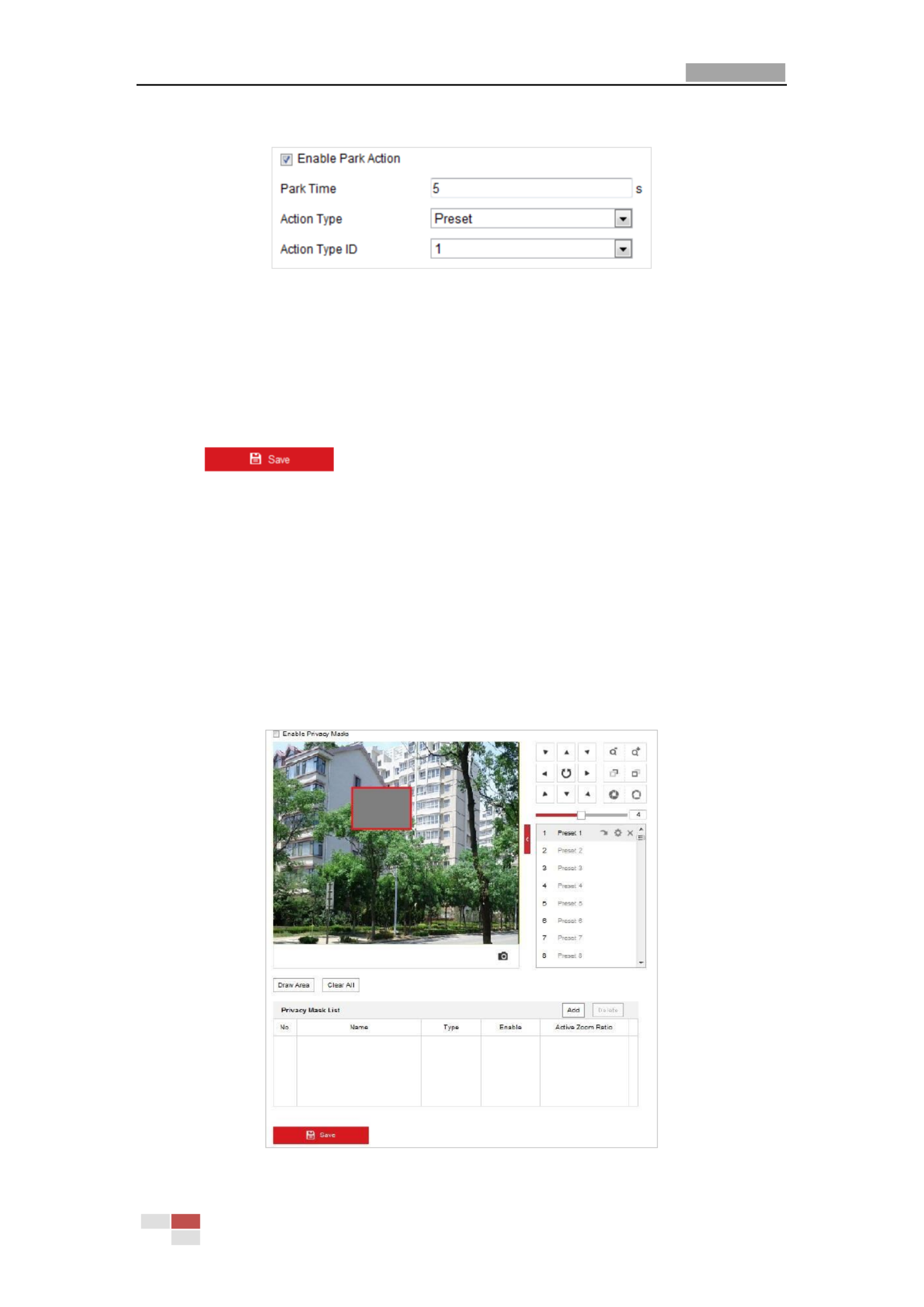
User Manual of Network PTZ Camera
© Hikvision
60
Configuration PTZ > Park Action >
Figure 5- Set the Park Action 29
2. Check the Enable Park Action checkbox.
3. Set the Park Time as the inactivity time of the camera before it starts the park actions.
4. Choose Action Type the from the down list. drop
5. If you select Patrol, Pattern, or Preset as Action Type, you need to select Action Type ID from
the dropdown list.
6. Click to save the settings.
5.4.5 Configuring Privacy Mask
Purpose:
Privacy mask enables you to cover certain areas on the live video to prevent certain spots in the
surveillance area from being live view and record . ed ed
Steps:
1. Enter the Privacy Mask settings interface:
Configuration PTZ Privacy Mask > >
Figure 5- Draw the Privacy Mask 30

User Manual of Network PTZ Camera
© Hikvision
61
2. Click the PTZ control buttons to find the area you want to set the privacy mask.
3. Click drag the mouse in the live video window to draw the area. ;
4. You can drag the corners of the red rectangle area to draw polygon mask. a
5. Click to finish drawing click to clear all of the areas you set without or
saving them.
6. Click to save the privacy mask, and it will be listed in the Privacy Mask List area; set
the value of Acve Zoom Rao on your demand, and then the mask will only appear when
the zoom ratio is greater than the predefined value.
Figure 5- Privacy Mask List 31
7. Check the checkbox of Enable Privacy Mask to enable this function.
5.4.6 Conguring Scheduled Tasks
Purpose:
You can configure the network speed dome to perform a certain action automatically in a
user-defined time period.
Steps:
1. Enter the Scheduled Task settings interface:
Conguraon PTZ Scheduled Tasks> >
Figure 5- Configure Scheduled Tasks 32

User Manual of Network PTZ Camera
© Hikvision
62
2. Check the Enable Scheduled Task checkbox.
3. Set the Park Time. You can set the park me (a period of inacvity) before the speed dome
starts the scheduled tasks.
4. Select the task type from the dropdown list.
5. Select the meline of a certain day, and drag the mouse to set the recording schedule (the
start me and end me of the recording task).
6. Aer you set the scheduled task, you can click copy the task to other days and
(oponal).
Figure 5- Edit the Schedule and Task Type 33
7. Click to save the setngs.
5.4.7 Clearing PTZ Conguraons
Purpose:
You can clear PTZ conguraons in this interface, including all presets, patrols, privacy masks, PTZ
limits, scheduled tasks and park acons.
Steps:
1. Enter the Clearing Conguration interface:
Conguraon PTZ > Clear Cong>
2. Check the checkbox of the items you want to clear.

User Manual of Network PTZ Camera
© Hikvision
63
Figure 5- Clear Cong 34
3. Click to clear the setngs.
5.4.8 Conguring Smart Tracking
Purpose:
The speed dome tracks the moving objects automacally aer you congure this function.
Steps:
1. Enter the Smart Tracking setngs interface:
Conguraon > PTZ > Smart Tracking
Figure 5- Congure Smart Tracking 35
2. Check the Enable Smart Tracking check box to enable smart tracking funcon.
3. Click the PTZ buons to select an object.
4. Click to set the current zoom ratio as the tracking zoom rao.

User Manual of Network PTZ Camera
© Hikvision
64
5. Set the tracking duration. The speed dome stops tracking when the duraon me is up. The
duraon ranges from 0 to 300 seconds.
Seing the duraon to 0 means that there no duraon when speed dome tracks. ’
This funcon varies depending on dierent camera models.
6. Click to clear the setngs.
5.4.9 Priorize PTZ
Steps:
1. Enter the Priorize PTZ interface:
Conguraon PTZ > > Priorize PTZ.
Figure 5- Position Seings 36
2. Select Network or RS-485 from the dropdown list
3. Set the delay me (Range 2-200s).
4. Click to save the sengs.

User Manual of Network PTZ Camera
© Hikvision
65
Chapter 6 Camera Conguraon
6.1 Conguring Network Sengs
The funcons vary depending on dierent camera models.
6.1.1 Basic Sengs
Conguring TCP/IP Sengs
Purpose:
TCP/IP sengs must be properly congured before you operate the camera over network. IPv4
and IPv6 are both supported.
Steps:
1. Enter TCP/IP setngs interface:
Conguraon > Network > Basic Setngs > TCP/IP
Figure 6-1 TCP/IP Setngs
2. Congure the NIC sengs, including the IPv4(IPv6) Address IPv4(IPv6) Subnet Mask, and
IPv4(IPv6) Default Gateway.

User Manual of Network PTZ Camera
© Hikvision
67
3. Select DDNS Type. Two DDNS types are selectable: DynDNS and NO-IP.
DynDNS:
Steps:
(1) Enter Server Address DynDNS (e.g. members.dyndns.org). of
(2) In the Domain text eld, enter the domain name obtained from the DynDNS website.
(3) Enter the of DynDNS server. Port
(4) Enter the User Name Password and registered the DynDNS website. on
(5) Click to save the sengs.
Figure 6-3 DynDNS Setngs
NO- : IP
Steps:
(1) Enter Server Address - . of NO IP
(2) In the Domain text eld, enter the domain name obtained from the - website. NO IP
(3) Enter the of NO-IP server. Port
(4) Enter the User Name Password and registered the - website. on NO IP
(5) Click to save the sengs.
Conguring PPPoE Setngs
Purpose:
If you have no router but only a modem, you can use Point- -Point Protocol over Ethernet to
(PPPoE) funcon.
Steps:
1. Enter the PPPoE seings interface:
Conguraon > Network > Basic Setngs > PPPoE
Figure 6-4 PPPoE Sengs
Produkt Specifikationer
| Mærke: | Hikvision |
| Kategori: | Overvågningskamera |
| Model: | DS-2DE5425IW-AE |
| Kode for international beskyttelse (IP): | IP66 |
| Type: | IP-sikkerhedskamera |
| Højde: | 345 mm |
| Vægt: | 3300 g |
| Produktfarve: | Hvid |
| Kompatible hukommelseskort: | MicroSD (TransFlash), MicroSDHC, MicroSDXC |
| Wi-Fi: | Ingen |
| Bluetooth: | Ingen |
| Formfaktor: | Kuppel |
| Relativ luftfugtighed ved drift (H-H): | 0 - 90 % |
| Ethernet LAN-porte (RJ-45): | 1 |
| Ethernet LAN: | Ja |
| Webbrowser: | Ja |
| Driftstemperatur (T-T): | -30 - 65 °C |
| Maksimal opløsning: | 2560 x 1440 pixel |
| Understøttelse af sprog: | BUL, CHI (TR), CZE, DAN, DEU, DUT, ENG, ESP, EST, FIN, FRE, GRE, HUN, ITA, JPN, KOR, LAT, LIT, NOR, POL, POR, RUM, RUS, SER, SLK, SLV, SWE, THA, TUR |
| Understøttede grafikopløsninger: | 352 x 240,352 x 288,640 x 480 (VGA),704 x 480,704 x 576,1280 x 720 (HD 720),1280 x 960,1920 x 1080 (HD 1080),2048 x 1536 (QXGA),2560 x 1440 |
| Forbindelsesteknologi: | Ledningsført |
| Lyd-output kanaler: | 1 kanaler |
| Strømforbrug (maks.): | 30 W |
| Netværksstandarder: | IEEE 802.1x |
| Understøttede netværksprotokoller: | IPv4/IPv6, HTTP, HTTPS, 802.1x, Qos, FTP, SMTP, UPnP, SNMP, DNS, DDNS, NTP, RTSP, RTCP, RTP, TCP/IP, UDP, IGMP, ICMP, DHCP, PPPoE, Bonjour |
| Webbaseret administration: | Ja |
| Servicekvalitet support (QoS): | Ja |
| IP-adresse filtrering: | Ja |
| Strømkilde type: | DC |
| Monteringstype: | Loft/væg |
| Diameter: | 208 mm |
| Indbygget kortlæser: | Ja |
| Indbygget HDD: | Ingen |
| Video komprimeringsformater: | H.264, H.264+, H.265, H.265+, M-JPEG |
| Understøttet placering: | Udendørs |
| Antal brugere: | 32 bruger(e) |
| Hvidbalance: | ATW, Auto, Fluorescent, Indoor, Manual, Outdoor, Sodium lamp |
| Sensortype: | CMOS |
| Samlet antal megapixels: | 4 MP |
| Støjreduktion: | Ja |
| Optisk zoom: | 25 x |
| Digital zoom: | 16 x |
| Fokus: | Motordrevet/manuel |
| Autofokus: | Ja |
| Maksimal størrelse på hukommelseskort: | 256 GB |
| Hældningsvinkelområde: | -15 - 90 ° |
| Progressiv scanning: | Ja |
| Voice codecs: | G.711alaw, G.711ulaw, G.722.1, G.726, MP2L2, PCM |
| Bredt dynamikområde (WDR): | Ja |
| Dag/nat funktion: | Ja |
| Infrarød (IR) cut-off filter: | Ja |
| Kamerapanorering kontrol: | Ja |
| Kontrol af kamerahældning: | Ja |
| Minimumsbelysning: | 0 Lux |
| Panoreringsområde: | 0 - 360 ° |
| Antal sensorer: | 1 |
| Optisk sensorstørrelse: | 1/2.8 " |
| Zoom kapacitet: | Ja |
| Nærmeste fokuseringsafstand: | 0.01 m |
| Maksimale blænderåbning tal: | 3.5 |
| Nattesyn: | Ja |
| LED type: | IR |
| Billedhastighed: | 30 fps |
| Forstærkningskontroltype: | Auto/manuel |
| Fortrolighedspolitik maskering: | Ja |
| Ethernet-grænsefladetype: | Hurtigt ethernet |
| Bevægelsessensor (video): | Ja |
| HTTPS -kryptering: | Ja |
| Antal kameraer: | 1 |
| Brændviddeområde: | - mm |
| Kameraets lukkerhastighed: | 1/1 - 1/30000 sek./side |
| Mindste blænderåbnimg tal: | 1.6 |
| Videostreaming: | Ja |
| Antal linser: | 1 |
| PTZ-kontrol: | Ja |
| Hældningshastighed: | 80 grader i sekundet |
| Panoreringshastighed: | 120 grader i sekundet |
| Nattesyn, afstand: | 150 m |
| Bit-rate: | 32-16384 Kbps |
| Region of Interest (ROI) kodning: | Ja |
| Kompensation for baggrundslys: | Ja |
| Objektivets synsvinkel, diagonal: | 61.5 ° |
| Antal sprog: | 32 |
| Objektivets synsvinkel, vandret: | 55 ° |
| Alarmindgang/-udgang: | Ja |
| Objektivets synsvinkel, lodret: | 33 ° |
| Lyd, indgående kanaler: | 1 |
| Highlight Compensation (HLC): | Ja |
| Forudindstillet hastighed: | 120 grader i sekundet |
| Støjreduktionsteknologi: | 3D støjreduktion |
| Adfærdsanalyse: | Intrusion detection, Line crossing detection, Object removal detection, Unattended baggage detection |
Har du brug for hjælp?
Hvis du har brug for hjælp til Hikvision DS-2DE5425IW-AE stil et spørgsmål nedenfor, og andre brugere vil svare dig
Overvågningskamera Hikvision Manualer

10 Februar 2025
10 Februar 2025
10 Februar 2025
10 Februar 2025
10 Februar 2025
5 Februar 2025
5 Februar 2025
12 Januar 2025
12 Januar 2025
7 Januar 2025
Overvågningskamera Manualer
- Overvågningskamera Bosch
- Overvågningskamera Denver
- Overvågningskamera Sony
- Overvågningskamera Canon
- Overvågningskamera Netis
- Overvågningskamera Samsung
- Overvågningskamera Panasonic
- Overvågningskamera Extech
- Overvågningskamera Moog
- Overvågningskamera TP-Link
- Overvågningskamera Philips
- Overvågningskamera Vitek
- Overvågningskamera Gigaset
- Overvågningskamera Pioneer
- Overvågningskamera Mitsubishi
- Overvågningskamera Braun
- Overvågningskamera Logitech
- Overvågningskamera Emos
- Overvågningskamera Google
- Overvågningskamera Technaxx
- Overvågningskamera HP
- Overvågningskamera Waeco
- Overvågningskamera Garmin
- Overvågningskamera Sanyo
- Overvågningskamera Grundig
- Overvågningskamera D-Link
- Overvågningskamera Arlo
- Overvågningskamera Motorola
- Overvågningskamera Asus
- Overvågningskamera Toshiba
- Overvågningskamera Pyle
- Overvågningskamera Kodak
- Overvågningskamera Furrion
- Overvågningskamera InFocus
- Overvågningskamera Nedis
- Overvågningskamera Friedland
- Overvågningskamera Abus
- Overvågningskamera Planet
- Overvågningskamera Adj
- Overvågningskamera Hama
- Overvågningskamera Creative
- Overvågningskamera Thomson
- Overvågningskamera Belkin
- Overvågningskamera Edimax
- Overvågningskamera Burg Wächter
- Overvågningskamera Clas Ohlson
- Overvågningskamera DataVideo
- Overvågningskamera Strong
- Overvågningskamera TRENDnet
- Overvågningskamera Smartwares
- Overvågningskamera Trevi
- Overvågningskamera Trust
- Overvågningskamera Laserliner
- Overvågningskamera Blaupunkt
- Overvågningskamera JVC
- Overvågningskamera Honeywell
- Overvågningskamera Uniden
- Overvågningskamera Buffalo
- Overvågningskamera Linksys
- Overvågningskamera Megasat
- Overvågningskamera Cisco
- Overvågningskamera EZVIZ
- Overvågningskamera König
- Overvågningskamera Elro
- Overvågningskamera Gembird
- Overvågningskamera Powerfix
- Overvågningskamera Alpine
- Overvågningskamera Netgear
- Overvågningskamera Maginon
- Overvågningskamera Yale
- Overvågningskamera Withings
- Overvågningskamera Nest
- Overvågningskamera Kerbl
- Overvågningskamera Vtech
- Overvågningskamera Exibel
- Overvågningskamera Genie
- Overvågningskamera Vaddio
- Overvågningskamera Bresser
- Overvågningskamera Western Digital
- Overvågningskamera Anker
- Overvågningskamera Digitus
- Overvågningskamera Zebra
- Overvågningskamera Jensen
- Overvågningskamera Alecto
- Overvågningskamera Flamingo
- Overvågningskamera Rollei
- Overvågningskamera Olympia
- Overvågningskamera Xiaomi
- Overvågningskamera Niceboy
- Overvågningskamera Aiptek
- Overvågningskamera Schneider
- Overvågningskamera B/R/K
- Overvågningskamera Marmitek
- Overvågningskamera Tesla
- Overvågningskamera Imou
- Overvågningskamera Ricoh
- Overvågningskamera Nexxt
- Overvågningskamera Aida
- Overvågningskamera APC
- Overvågningskamera Foscam
- Overvågningskamera Lorex
- Overvågningskamera Ikan
- Overvågningskamera Velleman
- Overvågningskamera LevelOne
- Overvågningskamera Marshall
- Overvågningskamera FLIR
- Overvågningskamera Perel
- Overvågningskamera Swann
- Overvågningskamera Vivotek
- Overvågningskamera Joblotron
- Overvågningskamera JUNG
- Overvågningskamera ORNO
- Overvågningskamera Binatone
- Overvågningskamera ZyXEL
- Overvågningskamera Fortinet
- Overvågningskamera Netatmo
- Overvågningskamera Tenda
- Overvågningskamera Eufy
- Overvågningskamera Ring
- Overvågningskamera M-e
- Overvågningskamera Overmax
- Overvågningskamera Somfy
- Overvågningskamera Y-cam
- Overvågningskamera Monacor
- Overvågningskamera ION
- Overvågningskamera Raymarine
- Overvågningskamera Ubiquiti Networks
- Overvågningskamera AVerMedia
- Overvågningskamera EnGenius
- Overvågningskamera Reolink
- Overvågningskamera Grandstream
- Overvågningskamera Trebs
- Overvågningskamera EVE
- Overvågningskamera Renkforce
- Overvågningskamera Marshall Electronics
- Overvågningskamera Manhattan
- Overvågningskamera SPC
- Overvågningskamera Caliber
- Overvågningskamera Pentatech
- Overvågningskamera Switel
- Overvågningskamera AVtech
- Overvågningskamera LogiLink
- Overvågningskamera Orion
- Overvågningskamera Eminent
- Overvågningskamera Kramer
- Overvågningskamera QSC
- Overvågningskamera Hanwha
- Overvågningskamera Brilliant
- Overvågningskamera Lanberg
- Overvågningskamera Hive
- Overvågningskamera Siedle
- Overvågningskamera BirdDog
- Overvågningskamera Evolveo
- Overvågningskamera Genius
- Overvågningskamera KJB Security Products
- Overvågningskamera Valueline
- Overvågningskamera Provision-ISR
- Overvågningskamera Quantum
- Overvågningskamera Axis
- Overvågningskamera ACTi
- Overvågningskamera CRUX
- Overvågningskamera Avanti
- Overvågningskamera Vimar
- Overvågningskamera Aluratek
- Overvågningskamera Dahua Technology
- Overvågningskamera Chacon
- Overvågningskamera SereneLife
- Overvågningskamera ZKTeco
- Overvågningskamera AG Neovo
- Overvågningskamera Stabo
- Overvågningskamera EtiamPro
- Overvågningskamera First Alert
- Overvågningskamera Speco Technologies
- Overvågningskamera Boss
- Overvågningskamera Broan
- Overvågningskamera Conceptronic
- Overvågningskamera Avidsen
- Overvågningskamera Crestron
- Overvågningskamera Lindy
- Overvågningskamera Kogan
- Overvågningskamera AVMATRIX
- Overvågningskamera Delta Dore
- Overvågningskamera Promise Technology
- Overvågningskamera Sitecom
- Overvågningskamera DiO
- Overvågningskamera Minox
- Overvågningskamera Intellinet
- Overvågningskamera V-TAC
- Overvågningskamera Qian
- Overvågningskamera August
- Overvågningskamera IDIS
- Overvågningskamera Geovision
- Overvågningskamera Schwaiger
- Overvågningskamera Steren
- Overvågningskamera Elmo
- Overvågningskamera AViPAS
- Overvågningskamera UniView
- Overvågningskamera Equip
- Overvågningskamera Alfatron
- Overvågningskamera REVO
- Overvågningskamera Aqara
- Overvågningskamera Ernitec
- Overvågningskamera Setti+
- Overvågningskamera BZBGear
- Overvågningskamera PTZ Optics
- Overvågningskamera AVer
- Overvågningskamera Ferguson
- Overvågningskamera Moxa
- Overvågningskamera Inovonics
- Overvågningskamera Bea-fon
- Overvågningskamera Profile
- Overvågningskamera WyreStorm
- Overvågningskamera Allnet
- Overvågningskamera Aldi
- Overvågningskamera Airlive
- Overvågningskamera Aritech
- Overvågningskamera ACME
- Overvågningskamera KlikaanKlikuit
- Overvågningskamera Marquant
- Overvågningskamera Ednet
- Overvågningskamera Lumens
- Overvågningskamera Hombli
- Overvågningskamera Naxa
- Overvågningskamera Miniland
- Overvågningskamera Xavax
- Overvågningskamera Gira
- Overvågningskamera Interlogix
- Overvågningskamera DSC
- Overvågningskamera Boyo
- Overvågningskamera Iget
- Overvågningskamera EverFocus
- Overvågningskamera Adesso
- Overvågningskamera Satel
- Overvågningskamera Notifier
- Overvågningskamera Monoprice
- Overvågningskamera Beafon
- Overvågningskamera Chuango
- Overvågningskamera MicroView
- Overvågningskamera ETiger
- Overvågningskamera Videcon
- Overvågningskamera INSTAR
- Overvågningskamera Advantech
- Overvågningskamera Digital Watchdog
- Overvågningskamera Moen
- Overvågningskamera Ganz
- Overvågningskamera MEE Audio
- Overvågningskamera Mobotix
- Overvågningskamera Kwikset
- Overvågningskamera Ikegami
- Overvågningskamera Leviton
- Overvågningskamera Pelco
- Overvågningskamera Approx
- Overvågningskamera ClearOne
- Overvågningskamera Ebode
- Overvågningskamera Oplink
- Overvågningskamera Dorr
- Overvågningskamera Sonic Alert
- Overvågningskamera Linear PRO Access
- Overvågningskamera Summer Infant
- Overvågningskamera SMC
- Overvågningskamera Topica
- Overvågningskamera Iiquu
- Overvågningskamera Verint
- Overvågningskamera Brinno
- Overvågningskamera Rostra
- Overvågningskamera Caddx
- Overvågningskamera Spyclops
- Overvågningskamera EKO
- Overvågningskamera Kguard
- Overvågningskamera Woonveilig
- Overvågningskamera Accsoon
- Overvågningskamera Mobi
- Overvågningskamera Surveon
- Overvågningskamera Hollyland
- Overvågningskamera Epcom
- Overvågningskamera Indexa
- Overvågningskamera Lutec
- Overvågningskamera Whistler
- Overvågningskamera ClearView
- Overvågningskamera VideoComm
- Overvågningskamera IMILAB
- Overvågningskamera 3xLOGIC
- Overvågningskamera Inkovideo
- Overvågningskamera Weldex
- Overvågningskamera SecurityMan
- Overvågningskamera Mach Power
- Overvågningskamera Canyon
- Overvågningskamera CNB Technology
- Overvågningskamera Tapo
- Overvågningskamera Aigis
- Overvågningskamera Exacq
- Overvågningskamera Brickcom
- Overvågningskamera Laxihub
- Overvågningskamera Securetech
- Overvågningskamera EFB Elektronik
- Overvågningskamera NetMedia
- Overvågningskamera Videotec
- Overvågningskamera Illustra
- Overvågningskamera Atlona
- Overvågningskamera Nivian
- Overvågningskamera Arenti
- Overvågningskamera E-bench
- Overvågningskamera Blow
- Overvågningskamera Syscom
- Overvågningskamera Tecno
- Overvågningskamera Night Owl
- Overvågningskamera Guardzilla
- Overvågningskamera Astak
- Overvågningskamera Blink
- Overvågningskamera Milestone Systems
- Overvågningskamera Zavio
- Overvågningskamera Campark
- Overvågningskamera IPX
- Overvågningskamera Dedicated Micros
- Overvågningskamera Hamlet
- Overvågningskamera Annke
- Overvågningskamera Qoltec
- Overvågningskamera Digimerge
- Overvågningskamera Feelworld
- Overvågningskamera Wisenet
- Overvågningskamera Infortrend
- Overvågningskamera Epiphan
- Overvågningskamera HiLook
- Overvågningskamera Compro
- Overvågningskamera Vimtag
- Overvågningskamera Sonoff
- Overvågningskamera Gewiss
- Overvågningskamera Alula
- Overvågningskamera Insteon
- Overvågningskamera Costar
- Overvågningskamera ALC
- Overvågningskamera Security Labs
- Overvågningskamera Comtrend
- Overvågningskamera Seneca
- Overvågningskamera Avigilon
- Overvågningskamera American Dynamics
- Overvågningskamera Vosker
- Overvågningskamera Sentry360
- Overvågningskamera Owltron
- Overvågningskamera Petcube
- Overvågningskamera Enabot
- Overvågningskamera Luis Energy
- Overvågningskamera Sir Gawain
- Overvågningskamera VisorTech
- Overvågningskamera Atlantis Land
- Overvågningskamera B & S Technology
- Overvågningskamera I3International
- Overvågningskamera Ecobee
- Overvågningskamera Turing
- Overvågningskamera Wasserstein
- Overvågningskamera Qolsys
- Overvågningskamera Control4
- Overvågningskamera Milesight
- Overvågningskamera GVI Security
- Overvågningskamera Conbrov
- Overvågningskamera HuddleCamHD
- Overvågningskamera Defender
- Overvågningskamera IOIO
- Overvågningskamera BIRDFY
- Overvågningskamera I-PRO
- Overvågningskamera DVDO
- Overvågningskamera TCP
- Overvågningskamera Bolin Technology
- Overvågningskamera Nextech
- Overvågningskamera Tuya
- Overvågningskamera Bolide
- Overvågningskamera Telycam
- Overvågningskamera Arecont Vision
- Overvågningskamera Schlage
Nyeste Overvågningskamera Manualer

7 April 2025
7 April 2025
6 April 2025
29 Marts 2025
28 Marts 2025
20 Marts 2025
20 Marts 2025
20 Marts 2025
13 Marts 2025
8 Marts 2025