Hikvision DS-2DF9C245IHS-DLW(T2) Manual
Hikvision
Overvågningskamera
DS-2DF9C245IHS-DLW(T2)
Læs nedenfor 📖 manual på dansk for Hikvision DS-2DF9C245IHS-DLW(T2) (139 sider) i kategorien Overvågningskamera. Denne guide var nyttig for 41 personer og blev bedømt med 4.5 stjerner i gennemsnit af 2 brugere
Side 1/139

Network Speed Dome
User Manual

User Manual of Network Speed Dome
© Hikvision
i
User Manual
© 2019 Hangzhou Hikvision Digital Technology Co., Ltd. All rights reserved.
This Manual is the property of Hangzhou Hikvision Digital Technology Co., Ltd. or its aliates
(hereinaer referred to as “Hikvision”), and it cannot be reproduced, changed, translated, or
distributed, parally or wholly, by any means, without the prior wrien permission of Hikvision.
Unless otherwise expressly stated herein, Hikvision does not make any warranes, guarantees or
representaons, express or implied, regarding to the Manual, any informaon contained herein.
About this Manual
The Manual includes instructions for using and managing the Product. Pictures, charts, images and all
other information hereinaer are for descripon and explanaon only. The informaon contained in
the Manual is subject to change, without noce, due to rmware updates or other reasons. Please
nd the latest version of this Manual at the Hikvision website (http://www.hikvision.com).
Please use this Manual with the guidance and assistance of professionals trained in supporng the
Product.
Trademarks Acknowledgement
and other Hikvision’s trademarks and logos are the properes of Hikvision in various
jurisdicons.
Other trademarks and logos menoned are the properes of their respecve owners.
LEGAL DISCLAIMER
TO THE MAXIMUM EXTENT PERMITTED BY APPLICABLE LAW, THIS MANUAL AND THE PRODUCT
DESCRIBED, WITH ITS HARDWARE, SOFTWARE AND FIRMWARE, ARE PROVIDED “AS IS” AND “WITH
ALL FAULTS AND ERRORS”. HIKVISION MAKES NO WARRANTIES, EXPRESS OR IMPLIED, INCLUDING
WITHOUT LIMITATION, MERCHANTABILITY, SATISFACTORY QUALITY, OR FITNESS FOR A PARTICULAR
PURPOSE. THE USE OF THE PRODUCT BY YOU IS AT YOUR OWN RISK. IN NO EVENT WILL HIKVISION BE
LIABLE TO YOU FOR ANY SPECIAL, CONSEQUENTIAL, INCIDENTAL, OR INDIRECT DAMAGES, INCLUDING,
AMONG OTHERS, DAMAGES FOR LOSS OF BUSINESS PROFITS, BUSINESS INTERRUPTION, OR LOSS OF
DATA, CORRUPTION OF SYSTEMS, OR LOSS OF DOCUMENTATION, WHETHER BASED ON BREACH OF
CONTRACT, TORT (INCLUDING NEGLIGENCE), PRODUCT LIABILITY, OR OTHERWISE, IN CONNECTION
WITH THE USE OF THE PRODUCT, EVEN IF HIKVISION HAS BEEN ADVISED OF THE POSSIBILITY OF SUCH
DAMAGES OR LOSS.
YOU ACKNOWLEDGE THAT THE NATURE OF INTERNET PROVIDES FOR INHERENT SECURITY RISKS, AND
HIKVISION SHALL NOT TAKE ANY RESPONSIBILITIES FOR ABNORMAL OPERATION, PRIVACY LEAKAGE
OR OTHER DAMAGES RESULTING FROM CYBER-ATTACK, HACKER ATTACK, VIRUS INSPECTION, OR
OTHER INTERNET SECURITY RISKS; HOWEVER, HIKVISION WILL PROVIDE TIMELY TECHNICAL SUPPORT
IF REQUIRED.
YOU AGREE TO USE THIS PRODUCT IN COMPLIANCE WITH ALL APPLICABLE LAWS, AND YOU ARE
SOLELY RESPONSIBLE FOR ENSURING THAT YOUR USE CONFORMS TO THE APPLICABLE LAW.
ESPECIALLY, YOU ARE RESPONSIBLE, FOR USING THIS PRODUCT IN A MANNER THAT DOES NOT
INFRINGE ON THE RIGHTS OF THIRD PARTIES, INCLUDING WITHOUT LIMITATION, RIGHTS OF PUBLICITY,
INTELLECTUAL PROPERTY RIGHTS, OR DATA PROTECTION AND OTHER PRIVACY RIGHTS. YOU SHALL
NOT USE THIS PRODUCT FOR ANY PROHIBITED END-USES, INCLUDING THE DEVELOPMENT OR
PRODUCTION OF WEAPONS OF MASS DESTRUCTION, THE DEVELOPMENT OR PRODUCTION OF
CHEMICAL OR BIOLOGICAL WEAPONS, ANY ACTIVITIES IN THE CONTEXT RELATED TO ANY NUCLEAR
EXPLOSIVE OR UNSAFE NUCLEAR FUEL-CYCLE, OR IN SUPPORT OF HUMAN RIGHTS ABUSES.
IN THE EVENT OF ANY CONFLICTS BETWEEN THIS MANUAL AND THE APPLICABLE LAW, THE LATER
PREVAILS.
05052420191107

Regulatory Informaon
FCC Informaon
Please take attenon that changes or modication not expressly approved by the party
responsible for compliance could void the user’s authority to operate the equipment.
FCC compliance: This equipment has been tested and found to comply with the limits for a Class
A digital device, pursuant to part 15 of the FCC Rules. These limits are designed to provide
reasonable protecon against harmful interference when the equipment is operated in a
commercial environment. This equipment generates, uses, and can radiate radio frequency
energy and, if not installed and used in accordance with the instruction manual, may cause
harmful interference to radio communicaons. Operaon of this equipment in a residenal area
is likely to cause harmful interference in which case the user will be required to correct the
interference at his own expense.
FCC Conditions
This device complies with part 15 of the FCC Rules. Operaon is subject to the following two
condions:
1. This device may not cause harmful interference.
2. This device must accept any interference received, including interference that may cause
undesired operaon.
EU Conformity Statement
This product and - if applicable - the supplied accessories too are marked with
"CE" and comply therefore with the applicable harmonized European standards
listed under the Low Voltage Direcve 2015/35/EU, the EMC Direcve 2014/30/EU,
the RoHS Direcve 2011/65/EU.
2012/19/ (WEEE direcve): Products marked with this symbol cannot be EU
disposed of as unsorted municipal waste in the European Union. For proper
recycling, return this product to your local supplier upon the purchase of
equivalent new equipment, or dispose of it at designated collecon points. For
more informaon see: www.recyclethis.info.
2006/66/EC (battery direcve): This product contains a battery that cannot be
disposed of as unsorted municipal waste in the European Union. See the product
documentaon for specic battery informaon. The battery is marked with this
symbol, which may include lettering to indicate cadmium (Cd), lead (Pb), or
mercury (Hg). For proper recycling, return the battery to your supplier or to a designated
collecon point. For more informaon, see: www.recyclethis.info.
Industry Canada ICES-003 Compliance
This device meets the CAN ICES-3 (A)/NMB-3(A) standards requirements.

Safety Instrucon
These instrucons are intended to ensure that the user can use the product correctly to avoid
danger or property loss.
The precauon measure is divided into ‘Warnings’ and ‘Cauons’:
Warnings: Serious injury or death may be caused if any of these warnings are neglected.
Cauons: Injury or equipment damage may be caused if any of these cauons are neglected.
Warnings Follow these safeguards to prevent
serious injury or death.
Cauons Follow these precauons to prevent
potenal injury or material damage.
Warnings:
Adopt the power adapter which can meet the safety extra low voltage (SELV) standard The .
power consumpon cannot be less than the required value.
Do not connect several devices to one power adapter as an adapter overload may cause
over-heang and can be a fire hazard.
When the product is installed on a wall or ceiling, the device should be rmly xed.
To reduce the risk of re or electrical shock, do not expose the indoor used product to rain or
moisture.
This installaon should be made by a qualied service person and should conform to all the
local codes.
Install blackouts equipment into the power supply circuit for convenient supply interrupon.
If the product does not work properly, contact your dealer or the nearest service center.
Never aempt to disassemble the product yourself. (We shall not assume any responsibility
for problems caused by unauthorized repair or maintenance.)
Cauons:
If the camera fails to synchronize local me with that of the network, you need to set up
camera me manually. Visit the camera (via web browser or client software) and enter
system settings interface for me sengs.
Make sure the power supply voltage is correct before using the product.
Do not drop the product or subject it to physical shock. Do not install the product on
vibratory surface or places.
Do not expose it to high electromagnec radiang environment.

Do not aim the lens at the strong light such as sun or incandescent lamp. The strong light can
cause fatal damage to the product.
The sensor may be burned out by a laser beam, so when any laser equipment is being used,
make sure that the surface of the sensor not be exposed to the laser beam.
For working temperature, refer to the specicaon manual for details.
To avoid heat accumulaon, good venlaon is required for a proper operang environment.
While shipping, the product should be packed in its original packing.
Use the provided glove when open up the product cover. Do not touch the product cover
with ngers directly, because the acidic sweat of the ngers may erode the surface coang of
the product cover.
Use a so and dry cloth when clean inside and outside surfaces of the product cover. Do not
use alkaline detergents.
Improper use or replacement of the battery may result in hazard of explosion. Use the
manufacturer recommended battery type.

Table of Contents
CHAPTER 1 OVERVIEW ................................................................................................................. 1
1.1 S YSTEM R EQUIREMENT ............................................................................................................. 1
1.2 F UNCTIONS ............................................................................................................................ 1
CHAPTER 2 NETWORK CONNECTION ............................................................................................ 4
2.1 S N C LAN ETTING THE ETWORK AMERA OVER THE ............................................................................ 4
2.1.1 Wiring over the LAN 4.......................................................................................................
2.1.2 Acvang the Camera 5....................................................................................................
2.2 S N C WAN ETTING THE ETWORK AMERA OVER THE ......................................................................... 10
2.2.1 Stac IP Connecon ...................................................................................................... 10
2.2.2 Dynamic IP Connecon . ................................................................................................ 11
CHAPTER 3 ACCESSING TO THE NETWORK SPEED DOME ............................................................ 13
3.1 A CCESSING BY W B EB ROWSERS ................................................................................................ 13
3.2 A C S CCESSING BY LIENT OFTWARE .............................................................................................. 14
CHAPTER 4 BASIC OPERATIONS ..................................................................................................16
4.1 P - A OWER UP CTION ............................................................................................................... 16
4.2 C ONFIGURING OCAL L PARAMETERS ............................................................................................ 16
4.3 L V P IVE IEW AGE .................................................................................................................... 17
4.4 S TARTING IVE IEWL V .............................................................................................................. 18
4.4.1 Live Operaon ..............................................................................................................18
4.4.2 Install Plug-in ................................................................................................................ 20
4.5 O PERATING ONTROLPTZ C ...................................................................................................... 21
4.5.1 PTZ Control Panel .......................................................................................................... 21
4.5.2 Auxiliary Funcons ........................................................................................................ 24
4.5.3 Seng/Calling a Preset ................................................................................................. 25
4.5.4 Seng/Calling a Patrol ................................................................................................. 27
4.5.5 One-touch Patrol........................................................................................................... 28
4.5.6 Seng/Calling a Paern ............................................................................................... 29
4.5.7 Conguring Wiper ........................................................................................................30
4.6 P LAYBACK ............................................................................................................................ 31
4.6.1 Play Back Video Files ....................................................................................................31
4.6.2 Downloading Video Files ............................................................................................... 33
4.7 P ICTURES ............................................................................................................................ 34
CHAPTER 5 SYSTEM CONFIGURATION .........................................................................................36
5.1 S TORAGE ETTINGSS ................................................................................................................ 36
5.1.1 Conguring Recording Schedule .................................................................................... 36
5.1.2 Conguring Capture Schedule ....................................................................................... 38
5.1.3 Conguring Net HDD .................................................................................................... 39
5.1.4 Conguring Cloud Storage .............................................................................................42
5.2 B E C ASIC VENT ONFIGURATION .................................................................................................. 42

5.2.1 Conguring Motion Detecon ....................................................................................... 43
5.2.2 Conguring Video Tampering Alarm .............................................................................. 48
5.2.3 Conguring Alarm Input ................................................................................................ 49
5.2.4 Conguring Alarm Output ............................................................................................. 50
5.2.5 Handling Excepon ....................................................................................................... 51
5.3 S E C MART VENT ONFIGURATION ................................................................................................ 52
5.3.1 Detecng Audio Excepon ............................................................................................52
5.3.2 Conguring Face Detecon ........................................................................................... 54
5.3.3 Conguring Intrusion Detection ..................................................................................... 54
5.3.4 Conguring Line Crossing Detecon .............................................................................. 56
5.3.5 Conguring Region Entrance Detecon .........................................................................58
5.3.6 Conguring Region Exing Detecon ............................................................................ 59
5.3.7 Unattended Baggage Detection ....................................................................................61
5.3.8 Object Removal Detecon ............................................................................................. 62
5.4 PTZ C ONFIGURATION ............................................................................................................. 64
5.4.1 Conguring Basic PTZ Parameters ................................................................................. 64
5.4.2 Conguring PTZ Limits ..................................................................................................66
5.4.3 Conguring Inial Posion ............................................................................................ 67
5.4.4 Conguring Park Acon ................................................................................................68
5.4.5 Conguring Privacy Mask .............................................................................................. 69
5.4.6 Conguring Scheduled Tasks .........................................................................................70
5.4.7 Clearing PTZ Conguraons .......................................................................................... 71
5.4.8 Conguring Smart Tracking ........................................................................................... 72
5.4.9 Priorize PTZ .................................................................................................................73
5.4.10 Position Seings ....................................................................................................... 73
5.4.11 Rapid Focus .............................................................................................................. 74
5.5 F ACE APTURE ONFIGURATIONC C ................................................................................................ 76
5.5.1 Overlay & Capture ........................................................................................................76
5.5.2 Rule .............................................................................................................................. 77
5.5.3 Advanced Conguration ................................................................................................ 79
5.6 S D MART ISPLAY .................................................................................................................... 81
CHAPTER 6 CAMERA CONFIGURATION ....................................................................................... 82
6.1 C ONFIGURING ETWORK ETTINGSN S ........................................................................................... 82
6.1.1 Basic Seings................................................................................................................ 82
6.1.2 Advanced Seings ......................................................................................................... 87
6.2 C ONFIGURING IDEO AND UDIO ETTINGSV A S ................................................................................. 99
6.2.1 Conguring Video Sengs ............................................................................................ 99
6.2.2 Conguring Audio Seings .......................................................................................... 101
6.2.3 Conguring ROI Sengs ............................................................................................. 102
6.2.4 Display Info. on Stream ............................................................................................... 103
6.3 C ONFIGURING MAGE ETTINGSI S .............................................................................................. 104
6.3.1 Conguring Display Seings ........................................................................................ 104
6.3.2 Conguring OSD Seings ............................................................................................ 110
6.3.3 Conguring Image Parameters Switch ......................................................................... 111

6.4 C ONFIGURING YSTEM ETTINGSS S ............................................................................................. 112
6.4.1 System Seings ........................................................................................................... 112
6.4.2 Maintenance .............................................................................................................. 117
6.4.3 Security ...................................................................................................................... 121
6.4.4 User Account............................................................................................................... 123
APPENDIX ...................................................................................................................................... 128
SADP S OFTWARE NTRODUCTIONI ....................................................................................................... 128
D CEVICE OMMUNICATION ATRIXM ...................................................................................................... 130
D C EVICE OMMAND.......................................................................................................................... 130

User Manual of Network Speed Dome
© Hikvision
1
Chapter 1 Overview
1.1 System Requirement
System requirement of web browser accessing is as follows:
Operang System: Microso Windows XP/Win7/Win8/Win10
CPU: Intel Penum IV 3.0 GHz or higher
RAM: 1G or higher
Display: 1024 × 768 resoluon or higher
Web Browser: Internet Explorer 8.0 to 11.0, Apple Safari 11 and above version, Mozilla Firefox .0
30.0 and above version, Google Chrome 31.0 and above version, and Microso Edge 16.16299
and above version.
Note:
If you are using Google Chrome 57 and its above version or Mozilla Firefox 52 and its above
version, plug-in installaon is not compulsory. But Picture Playback and of the camera are not
available. If you want to use the menoned funcon, change the web browser to Internet
Explorer, or click to download and install plug-in (only for Windows operaon
system).
1.2 Functions
Note:
The functions vary depending on dierent camera models.
PTZ Limits
The camera can be programmed to move within the PTZ limits (le/right, up/down).
Scan Modes
The camera provides 5 scan modes: auto scan, tilt scan, frame scan, random scan and panorama
scan.
Presets
A preset is a predened image posion. When the preset is called, the camera will automatically
move to the dened posion. The presets can be added, modied, deleted and called.
Label Display
The on-screen label of the preset tle, azimuth/elevation, zoom, me camera name can be and
displayed on the monitor. The displays of me and camera name can be programmed.
Auto Flips
In manual tracking mode, when a target object goes directly beneath the camera, the video will
automacally ip 180 degrees in horizontal direcon to maintain connuity of tracking. This
funcon can also be realized by auto mirror image depending on dierent camera models.
Privacy Mask
This funcon allows you to block or mask certain area of a scene, for prevent the personal ing
privacy from recording or live viewing. A masked area will move with pan and lt funcons and

automacally adjust in size as the lens zooms telephoto and wide.
3D Posioning
In the client soware, use the le key of mouse to click on the desired posion in the video
image and drag a rectangle area in the lower right direcon, then the camera system will move
the posion to the center and allow the rectangle area to zoom in. Use the le key of mouse to
drag a rectangle area in the upper le direcon to move the posion to the center and allow the
rectangle area to zoom out.
Proporonal Pan/Tilt
Proporonal pan/lt automacally reduces or increases the pan and lt speeds according to the
amount of zoom. At telephoto zoom setngs, the pan and lt speeds will be slower than at wide
zoom sengs. This keeps the image from moving too fast on the live view image when there is a
large amount of zoom.
Auto Focus
The auto focus enables the camera to focus automacally to maintain clear video images.
Day/Night Auto Switch
The cameras deliver color images during the day. And as light diminishes at night, the cameras
switch night mode and deliver black and white images with high quality. to
Slow Shutter
In slow shuer mode, the shuer speed will automacally slow down in low illuminaon
condions to maintain clear video images by extending the exposure me. The feature can be
enabled or disabled.
Backlight Compensaon (BLC)
If you focus on an object against strong backlight, the object will be too dark to be seen clearly.
The BLC (Backlight Compensaon) funcon can compensate light to the object in the front to
make it clear, but this causes the over-exposure of the background where the light is strong.
Wide Dynamic Range (WDR)
The wide dynamic range (WDR) funcon helps the camera provide clear images even under back
light circumstances. When there are both very bright and very dark areas simultaneously in the
eld of view, WDR balances the brightness level of the whole image and provide clear images
with details.
White Balance (WB)
White balance can remove the unrealisc color casts. White balance is the white rendion
funcon of the camera to adjust the color temperature according to the environment
automacally.
Patrol
A patrol is a memorized series of pre-dened preset funcon. The scanning speed between two
presets and the dwell me at the preset are programmable.
Pattern
A pattern is a memorized series of pan, lt, zoom, and preset funcons By default the focus and .
iris are in auto status during the pattern is being memorized.
Power O Memory
The camera supports the power o memory capability with the predened resume me. It allows
the camera to resume its previous posion after power is restored.
Scheduled Task

A me task is a precongured acon that can be performed automacally at a specic date and
me. The programmable acons include: auto scan, random scan, patrol 1-8, pattern 1- preset 4,
1- frame scan, panorama scan, lt scan, day, night, reboot, PT adjust, Aux Output, e . 8, tc
Park Acon
This feature allows the camera to start predened acon automacally aer a period of a
inacvity.
User Management
The camera allows you to edit users with dierent levels of permission, in the admin login status.
Mulple users are allowed to access and control the same network camera via network
simultaneously.
3D Digital Noise Reducon
Comparing with the general 2D digital noise reducon, the 3D digital noise reducon funcon
processes the noise between two frames besides processing the noise in one frame. The noise
will be much less and the video will be clearer.
User Manual of Network Speed Dome
© Hikvision
4
Chapter 2 Network Connecon
Notes:
You shall acknowledge that the use of the product with Internet access might be under
network security risks. For avoidance of any network aacks and informaon leakage,
strengthen your own protecon. If the product does not work properly, contact with your
dealer or the nearest service center.
To ensure the network security of the network camera, we recommend you to have the
network camera assessed and maintained termly. You can contact us if you need such
service.
Before you start:
If you want to set the network camera via LAN (Local Area Network), refer to a Secon 2.1
Seng the Network Camera over the LAN.
If you want to set the network camera via WAN (Wide Area Network), refer toa Secon 2.2
Seng the Network Camera over the WAN.
2.1 Seng the Network Camera over the LAN
Purpose:
To view and congure the camera via LAN, you need to connect the camera in the same subnet a
with your computer, and install the SADP or client software to search and change the IP of the
network camera.
Note:
For detailed introduction of SADP, refer to Appendix.
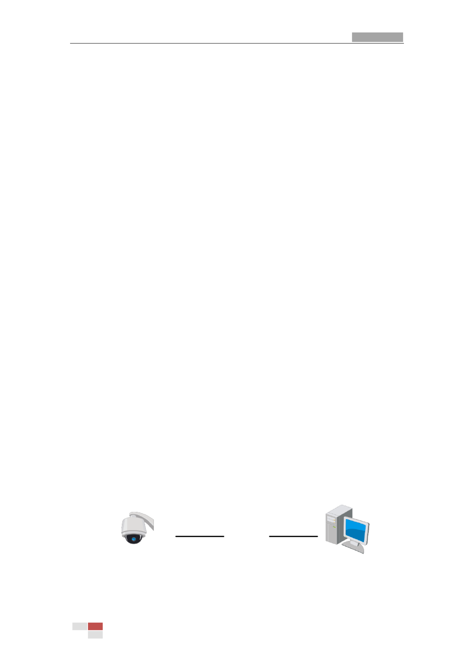
2.1.1 Wiring over the LAN
The following gures show the two ways of cable connection of network camera a and a
computer:
Purpose:
To test the network camera, you can directly connect the network camera to the computer
with a network cable as shown in Figure 2-1.
Refer to the Figure 2-2 set the network camera over the LAN via a switch or a router. to
Network Cable
Network Speed Dome
Computer
Figure 2-1 Connecng Directly

Proper configuration of all passwords and other security settings is the responsibility of
the installer and/or end-user.
4. Confirm the password.
5. Click to acvate the camera enter the live view interface. OK and
Acvaon via SADP Soware
SADP soware is used for detecng the online device, acvang the device, and resetng the
password.
Get the SADP software from the supplied disk or the ofcial website, and install the SADP
according to the prompts. Follow the steps to acvate the camera.
Steps:
1. Run the SADP soware to search the online devices.
2. Check the device status from the device list, and select acve device. an in
Select inacve device.
Input and conrm
password.
Figure 2-4 SADP Interface
Note:
The SADP soware supports acvating the camera in batch. Refer to the user manual of
SADP software for details.
3. Create a password and input the password in the password eld, and confirm the password.
For your privacy and to better protect your system against security risks, we strongly
recommend the use of strong passwords for all functions and network devices. The
password should be something of your own choosing (using a minimum of 8 characters,
including upper case letters, lower case letters, numbers and special characters) in order
to increase the security of your product.
Proper configuration of all passwords and other security settings is the responsibility of
the installer and/or end-user.
Note:

You can enable the Hik-Connect service for the device during acvaon. Hik-Connect funcon
varies depending on different speed dome models.
4. Click Acvate start acvaon. You can check whether the acvaon is completed on the to
popup window. If acvaon failed, make sure that the password meets the requirement and
then try again.
5. Change the device IP address to the same subnet with your computer by either modifying
the IP address manually or checking the Enable DHCP checkbox.
Figure 2-5 Modify the IP Address
6. Input the password and click Modify to acvate your IP address modicaon.
The batch IP address modicaon is supported by the SADP. Refer to the user manual of
SADP for details.
Acvaon via Client Soware
The client soware is versale video management software for mulple kinds of devices.
Get the client soware from the supplied disk or the ofcial website, and install the soware
according to the prompts. Follow the steps to acvate the camera.
Steps:
1. Run the client soware and the control panel of the software pops up, as shown in Figure
2-6.
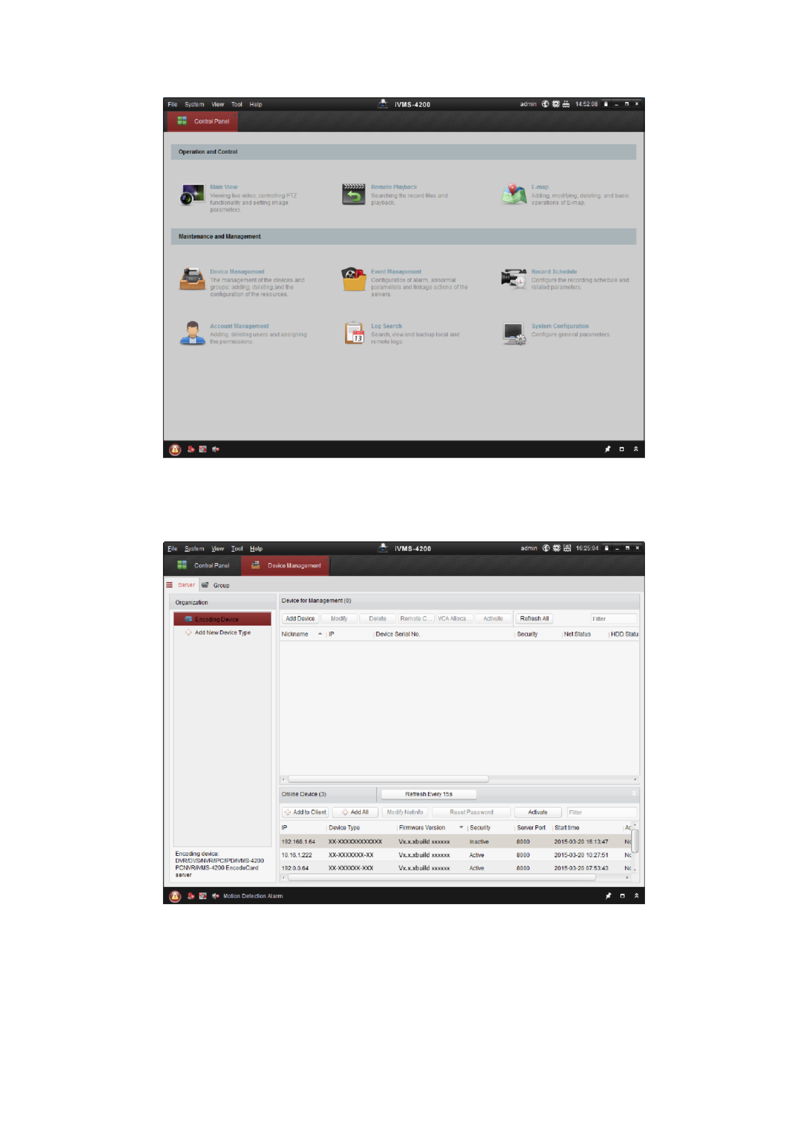
Figure 2-6 iVMS- Control Panel 4200
2. Click Device Management to enter the Device Management interface, as shown Figure in
2-7.
Figure 2-7 Device Management Interface
3. Check the device status from the device list, and select an inacve device.
4. Click Acvate to pop up the Acvaon interface.
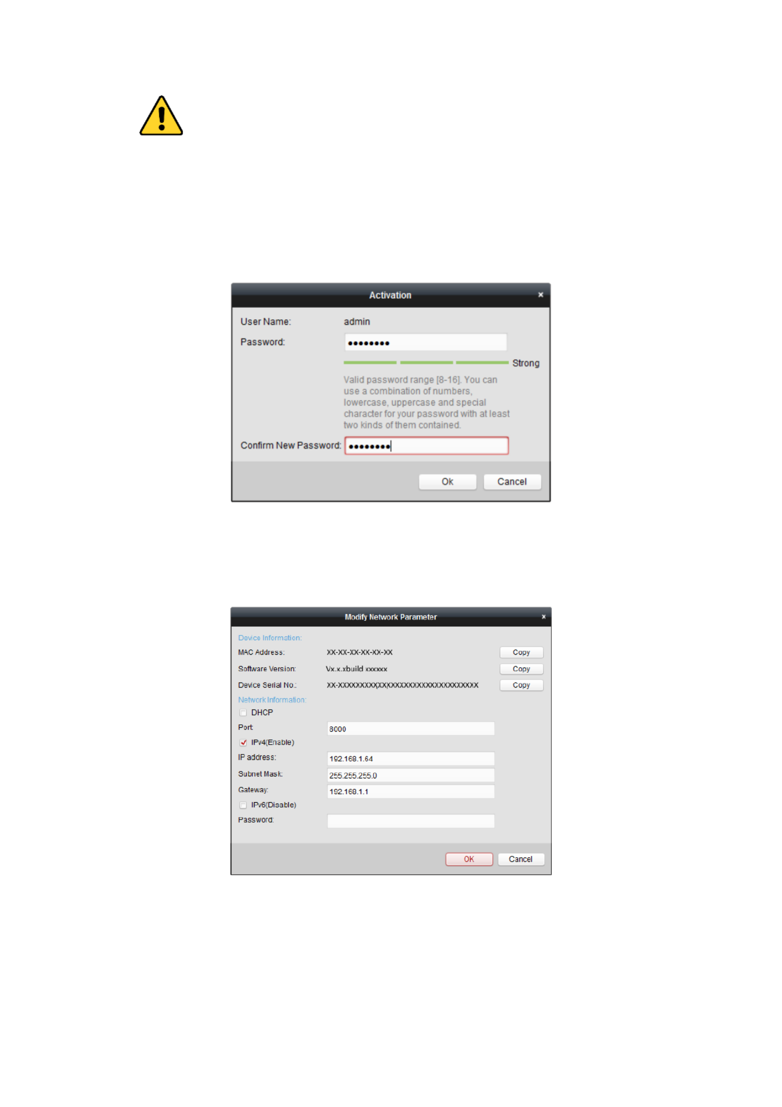
5. Create a password and input the password in the password field, and conrm the password.
For your privacy and to better protect your system against security risks, we strongly
recommend the use of strong passwords for all functions and network devices. The
password should be something of your own choosing (using a minimum of 8 characters,
including upper case letters, lower case letters, numbers and special characters) in order
to increase the security of your product.
Proper configuration of all passwords and other security settings is the responsibility of
the installer and/or end-user.
Figure 2-8 Acvaon Interface
6. Click to start acvaon. OK
7. Click Modify Nenfo to pop up the Network Parameter Modicaon interface, as shown in
Figure 2-9.
Figure 2-9 Modifying the Network Parameters
8. Change the device IP address to the same subnet with your computer by either modifying
the IP address manually or checking the Enable DHCP checkbox.
9. Input the password to acvate your IP address modificaon.

2.2.2 Dynamic IP Connecon
Before you start:
Apply a dynamic IP from an ISP. With the dynamic IP address, you can connect the network
camera to a modem or a router.
Connecng the network camera via a router
Steps:
1. Connect the network camera to the router.
2. In the camera, assign a LAN IP address, the subnet mask and the gateway. Refer to Secon
2.1.2 for detailed LAN conguraon.
3. In the router, set the PPPoE user name, password and confirm the password.
For your privacy and to better protect your system against security risks, we strongly
recommend the use of strong passwords for all functions and network devices. The
password should be something of your own choosing (using a minimum of 8 characters,
including upper case letters, lower case letters, numbers and special characters) in order
to increase the security of your product.
Proper configuration of all passwords and other security settings is the responsibility of
the installer and/or end-user.
4. Set port mapping. e.g. 80, 8000 and 554 ports. The steps for port mapping vary depending on
dierent routers. Call the router manufacturer for assistance with port mapping.
5. Apply a domain name from a domain name provider.
6. Configure the DDNS sengs in the setng interface of the router.
7. Visit the camera via the applied domain name.
Connecng the network camera via a modem
Purpose:
This camera supports the PPPoE auto dial-up funcon. The camera gets a public IP address by
ADSL dial-up after the camera is connected to a modem. You need to configure the PPPoE
parameters of the network camera. Refer to Secon 6.1.1 Conguring PPPoE Sengs for
detailed conguration.
Note:
The obtained IP address is dynamically assigned via PPPoE, so the IP address always changes aer
reboong the camera. To solve the inconvenience of the dynamic IP, you need to get a domain
name from the DDNS provider (e.g. DynDns.com). Follow the steps below for normal domain
name resoluon and private domain name resoluon to solve the problem.
Normal Domain Name Resoluon
Steps:
1. Apply a domain name from a domain name provider.
2. Configure the DDNS sengs in the DDNS Setngs interface of the network camera. Refer to
Secon 6.1.1 Conguring DDNS Sengs for detailed conguraon.

3. Visit the camera via the applied domain name.

3.2 Accessing by Client Soware
The product CD contains the client software. You can view the live video and manage the
camera with the client software.
Follow the installaon prompts to install the client soware and WinPca The conguraon p.
interface and live view interface of client soware are shown Figure 3-2. in
Figure 3-2 iVMS- Control Panel 4200
Figure 3-3 iVMS- Main Interface 4200

Figure 4-1 Live View Parameters
Record File Sengs: Set the saving path of the video les.
Record File Size: Select the packed size of manually recorded downloaded video lesand .
The size can be set to 256M, 512M or 1G.
Save record les to: Set the saving path for the manually recorded video les.
Save downloaded les to: Set the saving path for the downloaded video les in
interface.
Picture and Clip Sengs: Set the saving paths of the captured pictures and clipped video
les.
Save snapshots in live view to: Set the saving path the manually captured pictures in of
interface.
Save snapshots when playback to: Set the saving path the captured pictures in of
interface.
Save clips to: Set the saving path the clipped video les in interfa . of ce
You can click Browse to change the directory for saving video les, clips and pictures.
You can click Open to directly open the video les, clips and pictures.
3. Click to save the sengs.
4.3 Live View Page
Purpose:
The live video page allows you to view live video, capture images, realize PTZ control, set/call
presets and congure video parameters.
L the network camera enter the live view page, or you can click on the menu og in to
bar of the main page to enter the live view page.
Note:
The funcons vary depending on dierent camera models. Take the actual interface as standard.
Descripons of the Live View page:

Menu Bar
Live View
Window
Live View
Parameters
Show/hide
PTZ control
panel
PTZ Control
Preset/Patrol/Paern
Toolbar
Figure 4-2 Live View Page
Menu Bar:
Click each tab to enter Live View, Playback, Picture, and Configuraon page respecvely.
Click to display the help le of the network camera.
Click to logout the system.
Live View Window:
Display the live video.
Toolbar:
Operaons on the live view page, e.g., Count Pixel, Live View, Capture, Record, Audio on/o,
Regional Exposure, Regional Focus, etc.
PTZ Control:
Panning, Tilng, Focusing and Zooming acons of the network, as well as Light, Wiper, Auxiliary
Focus, Lens Inializaon Control, etc.and
Preset/Patrol/Paern:
Set and call the Preset/Patrol/Paern for the camera.
Live View Parameters:
Configure the Image Size, Stream Type, Plug-in Type, T -way audio of the live video, and wo
Display Captured Picture.
4.4 Starng Live View
4.4.1 Live Operaon
In the live view window as shown in Figure 4-3, click on the toolbar to start the live view of
the network.
Produkt Specifikationer
| Mærke: | Hikvision |
| Kategori: | Overvågningskamera |
| Model: | DS-2DF9C245IHS-DLW(T2) |
Har du brug for hjælp?
Hvis du har brug for hjælp til Hikvision DS-2DF9C245IHS-DLW(T2) stil et spørgsmål nedenfor, og andre brugere vil svare dig
Overvågningskamera Hikvision Manualer

10 Februar 2025
10 Februar 2025
10 Februar 2025
10 Februar 2025
10 Februar 2025
5 Februar 2025
5 Februar 2025
12 Januar 2025
12 Januar 2025
7 Januar 2025
Overvågningskamera Manualer
- Overvågningskamera Bosch
- Overvågningskamera Denver
- Overvågningskamera Sony
- Overvågningskamera Canon
- Overvågningskamera Netis
- Overvågningskamera Samsung
- Overvågningskamera Panasonic
- Overvågningskamera Extech
- Overvågningskamera Moog
- Overvågningskamera TP-Link
- Overvågningskamera Philips
- Overvågningskamera Vitek
- Overvågningskamera Gigaset
- Overvågningskamera Pioneer
- Overvågningskamera Mitsubishi
- Overvågningskamera Braun
- Overvågningskamera Logitech
- Overvågningskamera Emos
- Overvågningskamera Google
- Overvågningskamera Technaxx
- Overvågningskamera HP
- Overvågningskamera Waeco
- Overvågningskamera Garmin
- Overvågningskamera Sanyo
- Overvågningskamera Grundig
- Overvågningskamera D-Link
- Overvågningskamera Arlo
- Overvågningskamera Motorola
- Overvågningskamera Asus
- Overvågningskamera Toshiba
- Overvågningskamera Pyle
- Overvågningskamera Kodak
- Overvågningskamera Furrion
- Overvågningskamera InFocus
- Overvågningskamera Nedis
- Overvågningskamera Friedland
- Overvågningskamera Abus
- Overvågningskamera Planet
- Overvågningskamera Adj
- Overvågningskamera Hama
- Overvågningskamera Creative
- Overvågningskamera Thomson
- Overvågningskamera Belkin
- Overvågningskamera Edimax
- Overvågningskamera Burg Wächter
- Overvågningskamera Clas Ohlson
- Overvågningskamera DataVideo
- Overvågningskamera Strong
- Overvågningskamera TRENDnet
- Overvågningskamera Smartwares
- Overvågningskamera Trevi
- Overvågningskamera Trust
- Overvågningskamera Laserliner
- Overvågningskamera Blaupunkt
- Overvågningskamera JVC
- Overvågningskamera Honeywell
- Overvågningskamera Uniden
- Overvågningskamera Buffalo
- Overvågningskamera Linksys
- Overvågningskamera Megasat
- Overvågningskamera Cisco
- Overvågningskamera EZVIZ
- Overvågningskamera König
- Overvågningskamera Elro
- Overvågningskamera Gembird
- Overvågningskamera Powerfix
- Overvågningskamera Alpine
- Overvågningskamera Netgear
- Overvågningskamera Maginon
- Overvågningskamera Yale
- Overvågningskamera Withings
- Overvågningskamera Nest
- Overvågningskamera Kerbl
- Overvågningskamera Vtech
- Overvågningskamera Exibel
- Overvågningskamera Genie
- Overvågningskamera Vaddio
- Overvågningskamera Bresser
- Overvågningskamera Western Digital
- Overvågningskamera Anker
- Overvågningskamera Digitus
- Overvågningskamera Zebra
- Overvågningskamera Jensen
- Overvågningskamera Alecto
- Overvågningskamera Flamingo
- Overvågningskamera Rollei
- Overvågningskamera Olympia
- Overvågningskamera Xiaomi
- Overvågningskamera Niceboy
- Overvågningskamera Aiptek
- Overvågningskamera Schneider
- Overvågningskamera B/R/K
- Overvågningskamera Marmitek
- Overvågningskamera Tesla
- Overvågningskamera Imou
- Overvågningskamera Ricoh
- Overvågningskamera Nexxt
- Overvågningskamera Aida
- Overvågningskamera APC
- Overvågningskamera Foscam
- Overvågningskamera Lorex
- Overvågningskamera Ikan
- Overvågningskamera Velleman
- Overvågningskamera LevelOne
- Overvågningskamera Marshall
- Overvågningskamera FLIR
- Overvågningskamera Perel
- Overvågningskamera Swann
- Overvågningskamera Vivotek
- Overvågningskamera Joblotron
- Overvågningskamera JUNG
- Overvågningskamera ORNO
- Overvågningskamera Binatone
- Overvågningskamera ZyXEL
- Overvågningskamera Fortinet
- Overvågningskamera Netatmo
- Overvågningskamera Tenda
- Overvågningskamera Eufy
- Overvågningskamera Ring
- Overvågningskamera M-e
- Overvågningskamera Overmax
- Overvågningskamera Somfy
- Overvågningskamera Y-cam
- Overvågningskamera Monacor
- Overvågningskamera ION
- Overvågningskamera Raymarine
- Overvågningskamera Ubiquiti Networks
- Overvågningskamera AVerMedia
- Overvågningskamera EnGenius
- Overvågningskamera Reolink
- Overvågningskamera Grandstream
- Overvågningskamera Trebs
- Overvågningskamera EVE
- Overvågningskamera Renkforce
- Overvågningskamera Marshall Electronics
- Overvågningskamera Manhattan
- Overvågningskamera SPC
- Overvågningskamera Caliber
- Overvågningskamera Pentatech
- Overvågningskamera Switel
- Overvågningskamera AVtech
- Overvågningskamera LogiLink
- Overvågningskamera Orion
- Overvågningskamera Eminent
- Overvågningskamera Kramer
- Overvågningskamera QSC
- Overvågningskamera Hanwha
- Overvågningskamera Brilliant
- Overvågningskamera Lanberg
- Overvågningskamera Hive
- Overvågningskamera Siedle
- Overvågningskamera BirdDog
- Overvågningskamera Evolveo
- Overvågningskamera Genius
- Overvågningskamera KJB Security Products
- Overvågningskamera Valueline
- Overvågningskamera Provision-ISR
- Overvågningskamera Quantum
- Overvågningskamera Axis
- Overvågningskamera ACTi
- Overvågningskamera CRUX
- Overvågningskamera Avanti
- Overvågningskamera Vimar
- Overvågningskamera Aluratek
- Overvågningskamera Dahua Technology
- Overvågningskamera Chacon
- Overvågningskamera SereneLife
- Overvågningskamera ZKTeco
- Overvågningskamera AG Neovo
- Overvågningskamera Stabo
- Overvågningskamera EtiamPro
- Overvågningskamera First Alert
- Overvågningskamera Speco Technologies
- Overvågningskamera Boss
- Overvågningskamera Broan
- Overvågningskamera Conceptronic
- Overvågningskamera Avidsen
- Overvågningskamera Crestron
- Overvågningskamera Lindy
- Overvågningskamera Kogan
- Overvågningskamera AVMATRIX
- Overvågningskamera Delta Dore
- Overvågningskamera Promise Technology
- Overvågningskamera Sitecom
- Overvågningskamera DiO
- Overvågningskamera Minox
- Overvågningskamera Intellinet
- Overvågningskamera V-TAC
- Overvågningskamera Qian
- Overvågningskamera August
- Overvågningskamera IDIS
- Overvågningskamera Geovision
- Overvågningskamera Schwaiger
- Overvågningskamera Steren
- Overvågningskamera Elmo
- Overvågningskamera AViPAS
- Overvågningskamera UniView
- Overvågningskamera Equip
- Overvågningskamera Alfatron
- Overvågningskamera REVO
- Overvågningskamera Aqara
- Overvågningskamera Ernitec
- Overvågningskamera Setti+
- Overvågningskamera BZBGear
- Overvågningskamera PTZ Optics
- Overvågningskamera AVer
- Overvågningskamera Ferguson
- Overvågningskamera Moxa
- Overvågningskamera Inovonics
- Overvågningskamera Bea-fon
- Overvågningskamera Profile
- Overvågningskamera WyreStorm
- Overvågningskamera Allnet
- Overvågningskamera Aldi
- Overvågningskamera Airlive
- Overvågningskamera Aritech
- Overvågningskamera ACME
- Overvågningskamera KlikaanKlikuit
- Overvågningskamera Marquant
- Overvågningskamera Ednet
- Overvågningskamera Lumens
- Overvågningskamera Hombli
- Overvågningskamera Naxa
- Overvågningskamera Miniland
- Overvågningskamera Xavax
- Overvågningskamera Gira
- Overvågningskamera Interlogix
- Overvågningskamera DSC
- Overvågningskamera Boyo
- Overvågningskamera Iget
- Overvågningskamera EverFocus
- Overvågningskamera Adesso
- Overvågningskamera Satel
- Overvågningskamera Notifier
- Overvågningskamera Monoprice
- Overvågningskamera Beafon
- Overvågningskamera Chuango
- Overvågningskamera MicroView
- Overvågningskamera ETiger
- Overvågningskamera Videcon
- Overvågningskamera INSTAR
- Overvågningskamera Advantech
- Overvågningskamera Digital Watchdog
- Overvågningskamera Moen
- Overvågningskamera Ganz
- Overvågningskamera MEE Audio
- Overvågningskamera Mobotix
- Overvågningskamera Kwikset
- Overvågningskamera Ikegami
- Overvågningskamera Leviton
- Overvågningskamera Pelco
- Overvågningskamera Approx
- Overvågningskamera ClearOne
- Overvågningskamera Ebode
- Overvågningskamera Oplink
- Overvågningskamera Dorr
- Overvågningskamera Sonic Alert
- Overvågningskamera Linear PRO Access
- Overvågningskamera Summer Infant
- Overvågningskamera SMC
- Overvågningskamera Topica
- Overvågningskamera Iiquu
- Overvågningskamera Verint
- Overvågningskamera Brinno
- Overvågningskamera Rostra
- Overvågningskamera Caddx
- Overvågningskamera Spyclops
- Overvågningskamera EKO
- Overvågningskamera Kguard
- Overvågningskamera Woonveilig
- Overvågningskamera Accsoon
- Overvågningskamera Mobi
- Overvågningskamera Surveon
- Overvågningskamera Hollyland
- Overvågningskamera Epcom
- Overvågningskamera Indexa
- Overvågningskamera Lutec
- Overvågningskamera Whistler
- Overvågningskamera ClearView
- Overvågningskamera VideoComm
- Overvågningskamera IMILAB
- Overvågningskamera 3xLOGIC
- Overvågningskamera Inkovideo
- Overvågningskamera Weldex
- Overvågningskamera SecurityMan
- Overvågningskamera Mach Power
- Overvågningskamera Canyon
- Overvågningskamera CNB Technology
- Overvågningskamera Tapo
- Overvågningskamera Aigis
- Overvågningskamera Exacq
- Overvågningskamera Brickcom
- Overvågningskamera Laxihub
- Overvågningskamera Securetech
- Overvågningskamera EFB Elektronik
- Overvågningskamera NetMedia
- Overvågningskamera Videotec
- Overvågningskamera Illustra
- Overvågningskamera Atlona
- Overvågningskamera Nivian
- Overvågningskamera Arenti
- Overvågningskamera E-bench
- Overvågningskamera Blow
- Overvågningskamera Syscom
- Overvågningskamera Tecno
- Overvågningskamera Night Owl
- Overvågningskamera Guardzilla
- Overvågningskamera Astak
- Overvågningskamera Blink
- Overvågningskamera Milestone Systems
- Overvågningskamera Zavio
- Overvågningskamera Campark
- Overvågningskamera IPX
- Overvågningskamera Dedicated Micros
- Overvågningskamera Hamlet
- Overvågningskamera Annke
- Overvågningskamera Qoltec
- Overvågningskamera Digimerge
- Overvågningskamera Feelworld
- Overvågningskamera Wisenet
- Overvågningskamera Infortrend
- Overvågningskamera Epiphan
- Overvågningskamera HiLook
- Overvågningskamera Compro
- Overvågningskamera Vimtag
- Overvågningskamera Sonoff
- Overvågningskamera Gewiss
- Overvågningskamera Alula
- Overvågningskamera Insteon
- Overvågningskamera Costar
- Overvågningskamera ALC
- Overvågningskamera Security Labs
- Overvågningskamera Comtrend
- Overvågningskamera Seneca
- Overvågningskamera Avigilon
- Overvågningskamera American Dynamics
- Overvågningskamera Vosker
- Overvågningskamera Sentry360
- Overvågningskamera Owltron
- Overvågningskamera Petcube
- Overvågningskamera Enabot
- Overvågningskamera Luis Energy
- Overvågningskamera Sir Gawain
- Overvågningskamera VisorTech
- Overvågningskamera Atlantis Land
- Overvågningskamera B & S Technology
- Overvågningskamera I3International
- Overvågningskamera Ecobee
- Overvågningskamera Turing
- Overvågningskamera Wasserstein
- Overvågningskamera Qolsys
- Overvågningskamera Control4
- Overvågningskamera Milesight
- Overvågningskamera GVI Security
- Overvågningskamera Conbrov
- Overvågningskamera HuddleCamHD
- Overvågningskamera Defender
- Overvågningskamera IOIO
- Overvågningskamera BIRDFY
- Overvågningskamera I-PRO
- Overvågningskamera DVDO
- Overvågningskamera TCP
- Overvågningskamera Bolin Technology
- Overvågningskamera Nextech
- Overvågningskamera Tuya
- Overvågningskamera Bolide
- Overvågningskamera Telycam
- Overvågningskamera Arecont Vision
- Overvågningskamera Schlage
Nyeste Overvågningskamera Manualer

7 April 2025
7 April 2025
6 April 2025
29 Marts 2025
28 Marts 2025
20 Marts 2025
20 Marts 2025
20 Marts 2025
13 Marts 2025
8 Marts 2025