Hikvision DS-2TD8166-100C2F Manual
Hikvision
Overvågningskamera
DS-2TD8166-100C2F
Læs nedenfor 📖 manual på dansk for Hikvision DS-2TD8166-100C2F (151 sider) i kategorien Overvågningskamera. Denne guide var nyttig for 8 personer og blev bedømt med 4.5 stjerner i gennemsnit af 2 brugere
Side 1/151

Therm -spectrum al Bi
Network Positioning System
User Manual
COPYRIGHT © 2018 Hangzhou Hikvision Digital Technology Co., Ltd.

User Manual of Thermal Bi-spectrum Network Positioning System
© Hikvision
i
User Manual
User Manual
User Manual
User ManualUser Manual
COPYRIGHT © 2018 Hangzhou Hikvision Digital Technology Co., Ltd.
ALL RIGHTS
ALL RIGHTS
ALL RIGHTS
ALL RIGHTSALL RIGHTS RESERVED.
RESERVED.
RESERVED.
RESERVED. RESERVED.
Any and all information, including, among others, wordings, pictures, graphs are the properties
of Hangzhou Hikvision Digital Technology Co., Ltd. or its subsidiaries (hereinafter referred to be
“Hikvision”). This user manual (hereinafter referred to be “the Manual”) cannot be reproduced,
changed, translated, or distributed, partially or wholly, by any means, without the prior written
permission of Hikvision. Unless otherwise stipulated, Hikvision does not make any warranties,
guarantees or representations, express or implied, regarding to the Manual.
About this
About this
About this
About this About this Manual
Manual
Manual
Manual Manual
This Manual is applicable to Therm -spectrum Network Positioning Systemal Bi .
The Manual includes instructions for using and managing the product. Pictures, charts,
images and all other information hereinafter are for description and explanation only. The
information contained in the Manual is subject to change, without notice, due to firmware
updates or other reasons. Please find the latest version in the company website
( ).
http://overseas.hikvision.com/en/
Please use this user manual under the guidance of professionals.
Trademark
Trademark
Trademark
TrademarkTrademarks Acknowledgeme
s Acknowledgeme
s Acknowledgeme
s Acknowledgemes Acknowledgement
nt
nt
nt nt
and other Hikvision’s trademarks and logos are the properties of
Hikvision in various jurisdictions. Other trademarks and logos mentioned below are the
properties of their respective owners.
Legal Discla
Legal Discla
Legal Discla
Legal DisclaLegal Disclaimer
imer
imer
imer imer
TO THE MAXIMUM EXTENT PERMITTED BY APPLICABLE LAW, THE PRODUCT DESCRIBED,
WITH ITS HARDWARE, SOFTWARE AND FIRMWARE, IS PROVIDED “AS IS”, WITH ALL FAULTS
AND ERRORS, AND HIKVISION MAKES NO WARRANTIES, EXPRESS OR IMPLIED, INCLUDING
WITHOUT LIMITATION, MERCHANTABILITY, SATISFACTORY QUALITY, FITNESS FOR A
PARTICULAR PURPOSE, AND NON-INFRINGEMENT OF THIRD PARTY. IN NO EVENT WILL
HIKVISION, ITS DIRECTORS, OFFICERS, EMPLOYEES, OR AGENTS BE LIABLE TO YOU FOR
ANY SPECIAL, CONSEQUENTIAL, INCIDENTAL, OR INDIRECT DAMAGES, INCLUDING, AMONG
OTHERS, DAMAGES FOR LOSS OF BUSINESS PROFITS, BUSINESS INTERRUPTION, OR LOSS
OF DATA OR DOCUMENTATION, IN CONNECTION WITH THE USE OF THIS PRODUCT, EVEN IF
HIKVISION HAS BEEN ADVISED OF THE POSSIBILITY OF SUCH DAMAGES.
REGARDING TO THE PRODUCT WITH INTERNET ACCESS, THE USE OF PRODUCT SHALL BE
WHOLLY AT YOUR OWN RISKS. HIKVISION SHALL NOT TAKE ANY RESPONSIBILITES FOR
ABNORMAL OPERATION, PRIVACY LEAKAGE OR OTHER DAMAGES RESULTING FROM
CYBER ATTACK, HACKER ATTACK, VIRUS INSPECTION, OR OTHER INTERNET SECURITY
RISKS; HOWEVER, HIKVISION WILL PROVIDE TIMELY TECHNICAL SUPPORT IF REQUIRED.
SURVEILLANCE LAWS VARY BY JURISDICTION. PLEASE CHECK ALL RELEVANT LAWS IN

User Manual of Thermal Network Positioning system
© Hikvision
ii
YOUR JURISDICTION BEFORE USING THIS PRODUCT IN ORDER TO ENSURE THAT YOUR
USE CONFORMS THE APPLICABLE LAW. HIKVISION SHALL NOT BE LIABLE IN THE EVENT
THAT THIS PRODUCT IS USED WITH ILLEGITIMATE PURPOSES.
IN THE EVENT OF ANY CONFLICTS BETWEEN THIS MANUAL AND THE APPLICABLE LAW,
THE LATER PREVAILS.

User Manual of Thermal Network Positioning system
© Hikvision
iii
Regulatory Information
Regulatory Information
Regulatory Information
Regulatory Information Regulatory Information
FCC Informati
FCC Informati
FCC Informati
FCC InformatiFCC Information
on
on
on on
Please take attention that changes or modification not expressly approved by the party
responsible for compliance could void the user’s authority to operate the equipment.
FCC compliance
FCC compliance
FCC compliance
FCC complianceFCC compliance:
:
:
: : This equipment has been tested and found to comply with the limits for
a digital device, pursuant to part 15 of the FCC Rules. These limits are designed to provide
reasonable protection against harmful interference when the equipment is operated in a
commercial environment. This equipment generates, uses, and can radiate radio
frequency energy and, if not installed and used in accordance with the instruction manual,
may cause harmful interference to radio communications. Operation of this equipment in
a residential area is likely to cause harmful interference in which case the user will be
required to correct the interference at his own expense.
FCC Conditions
FCC Conditions
FCC Conditions
FCC ConditionsFCC Conditions
This device complies with part 15 of the FCC Rules. Operation is subject to the following
two conditions:
1. This device may not cause harmful interference.
2. This device must accept any interference received, including interference that may
cause undesired operation.
EU Conformity
EU Conformity
EU Conformity
EU Conformity EU Conformity Statement
Statement
Statement
Statement Statement
This product and - if applicable - the supplied accessories too are marked
with "CE" and comply therefore with the applicable harmonized European
standards listed under the Low Voltage Directive 2006/95/EC, the EMC
Directive 2014/30 U, the RoHS Directive 2011/65/EU. /E
2012/19/EU (WEEE directive): Products marked with this symbol cannot
be disposed of as unsorted municipal waste in the European Union. For
proper recycling, return this product to your local supplier upon the
purchase of equivalent new equipment, or dispose of it at designated
collection points. For more information see: www.recyclethis.info.
2006/66/EC (battery directive): This product contains a battery that cannot
be disposed of as unsorted municipal waste in the European Union. See
the product documentation for specific battery information. The battery is
marked with this symbol, which may include lettering to indicate cadmium
(Cd), lead (Pb), or mercury (Hg). For proper recycling, return the battery to your supplier or
to a designated collection point. For more information see: www.recyclethis.info.
Industry Cana
Industry Cana
Industry Cana
Industry CanaIndustry Canada ICES-
da ICES-
da ICES-
da ICES-da ICES-003 Compliance
003 Compliance
003 Compliance
003 Compliance003 Compliance
This device meets the CAN ICES-3 (A)/NMB-3(A) standards requirements.

User Manual of Thermal Network Positioning system
© Hikvision
iv
Safety Instruction
Safety Instruction
Safety Instruction
Safety Instruction Safety Instruction
These instructions are intended to ensure that the user can use the product correctly to
avoid danger or property loss.
The precaution measure is divided into ‘Warnings’ and ‘Cautions’:
Warnings
Warnings
Warnings
WarningsWarnings: Serious injury or death may be caused if any of these warnings are neglected.
Cautions
Cautions
Cautions
CautionsCautions: Injury or equipment damage may be caused if any of these cautions are
neglected.
Warnings
Warnings
Warnings
WarningsWarnings Follow these safeguards to
prevent serious injury or death.
Cautions
Cautions
Cautions
CautionsCautions Follow these precautions to
prevent potential injury or material damage.
Warnings
Warnings
Warnings
WarningsWarnings
The device should be used in compliance with local laws and electrical safety regulations. Refer to the
appropriate documentation for detailed information.
The input voltage should conform to IEC60950-1 standard: SELV (Safety Extra Low Voltage) and the
Limited Power Source (24 VAC/12 VDC). Refer to the appropriate documentation for detailed
information.
DO NOT connect multiple devices to one power adapter, to avoid over-heating or fire hazards caused
by overload.
Make sure the plug is properly connected to the power socket.
If smoke, odor, or noise arises from the device, immediately turn off the power, unplug the power cable,
and contact the service center.
The installer and user are responsible for password and security configuration and its settings.
Both internal and external grounds should be connected properly. (The cross section area of the
grounding wire must be no less than 4 mm2, and no less than that of the phase connector).
Cautions
Cautions
Cautions
CautionsCautions
Do not drop the device or subject it to physical shock.
Wipe the device gently with a clean cloth and a small quantity of ethanol, if necessary.
Do not aim the lens at the sun or any other bright light.
When any laser equipment is in use, make sure that the device lens is not exposed to the laser beam,
or it may burn out.
Do not expose the device to high electromagnetic radiation or extremely hot, cold, dusty, or damp
environments.
Place the device in a dry and well-ventilated environment.
Keep non-waterproof devices away from liquids.
Keep the device in original or similar packaging while transporting it.
A few device components (e.g., electrolytic capacitor) require regular replacement. The average
lifespan varies, so periodic checking is recommended. Contact your dealer for details.
Improper use or replacement of the battery may result in explosion hazard. Replace with the same or
equivalent type only. Dispose of used batteries in conformance with the instructions provided by the
battery manufacturer.
Never attempt to disassemble the device.
050540 80709 10

User Manual of Thermal Network Positioning system
© Hikvision
v
Table of Contents
Chapter 1
Chapter 1
Chapter 1
Chapter 1Chapter 1 Overview
Overview
Overview
OverviewOverview
..........................................................
..........................................................
..........................................................
....................................................................................................................
1
1
1
11
1.1 Overview ................................................................ 1
1.2 System Requirement ...................................................... 1
1.3 Functions ................................................................ 1
Chapter 2
Chapter 2
Chapter 2
Chapter 2Chapter 2 Network
Network
Network
Network Network Connection
Connection
Connection
ConnectionConnection
5
5
5
55
................................................
................................................
................................................
................................................................................................
2.1 Setting the Network Positioning System over the L AN .......................... 5
2.1.1 Wiring over the LAN
...................................................... 5
2.1.2 Activating the Positioning system
........................................... 6
2.2 Setting the Network Positioning system over the WAN ........................ 11
2.2.1 Static IP Connection
..................................................... 11
2.2.2 Dynamic IP Connection
.................................................. 12
Chapter 3
Chapter 3
Chapter 3
Chapter 3Chapter 3 Access to the
Access to the
Access to the
Access to theAccess to the Network Positio
Network Positio
Network Positio
Network Positio Network Positioning system
ning system
ning system
ning systemning system
.............................
.............................
.............................
..........................................................
15
15
15
1515
3.1 Accessing by Web Browsers ............................................... 15
3.2 Accessing by Client Software .............................................. 16
Chapter 4
Chapter 4
Chapter 4
Chapter 4Chapter 4 Basic Operatio
Basic Operatio
Basic Operatio
Basic OperatioBasic Operations
ns
ns
nsns
..................................................
..................................................
..................................................
....................................................................................................
18
18
18
1818
4.1 Configuring Local Parameters ............................................. 18
4.2 Live View Page .......................................................... 20
4.3 Starting Live View ........................................................ 21
4.3.1 Toolbar Description
..................................................... 21
4.4 Operating PTZ Control .................................................... 23
4.4.1 PTZ Control Panel
...................................................... 23
4.4.2 Auxiliary Functions
...................................................... 25
4.4.3 Setting / Calling a Preset
................................................. 26
4.4.4 Setting / Calling a Patrol
................................................. 29
4.4.5 One-touch Patrol
....................................................... 30
4.4.6 Setting / Calling a Pattern
................................................ 31
4.5 Playback ............................................................... 32
4.5.1 Play Back Video Files
.................................................... 32
4.5.2 Downloading Video Files
................................................. 35
4.6 P tures ic ................................................................ 36
Chapter 5
Chapter 5
Chapter 5
Chapter 5Chapter 5 System Co
System Co
System Co
System CoSystem Configuration
nfiguration
nfiguration
nfigurationnfiguration
..............................................
..............................................
..............................................
............................................................................................
38
38
38
3838
5.1 Storage Settings ......................................................... 38
5.1.1 Configuring Recording Schedule
........................................... 38
5.1.2 Configuring Capture Schedule
............................................. 40
5.1.3 Configuring Net HDD
.................................................... 42
5.2 Event Configuration ...................................................... 44
5.2.1 Configuring Motion Detection
............................................. 44
5.2.2 Configuring Video Tampering Alarm
........................................ 49

User Manual of Thermal Network Positioning system
© Hikvision
vi
5.2.3 Configuring Alarm Input
.................................................. 50
5.2.4 Configuring Alarm Output
................................................ 52
5.2.5 Handling Exception
..................................................... 53
5.2.1 Detecting Audio Exception
................................................ 53
5.3 Fire Source Detection Configuration ........................................ 55
5.3.1 Configuring Initial Position
................................................ 56
5.3.2 Configuring Dynamic Fire Source Detection
.................................. 57
5.3.3 Configuring Fire Source Detection Shield
.................................... 59
5.4 Temperature Measurement ............................................... 61
5.4.1 Temperature Measurement Configuration
................................... 61
5.4.2 Configuring Temperature Measurement Rule
................................. 62
5.4.3 Linkage Method
........................................................ 67
5.4.4 Search History Temperature
.............................................. 67
5.4.5 VCA Rule Display
....................................................... 68
Chapter 6
Chapter 6
Chapter 6
Chapter 6Chapter 6 VCA Config
VCA Config
VCA Config
VCA ConfigVCA Configuration
uration
uration
urationuration
................................
................................
................................
.................................................................................
.................
.................
..................................
69
69
69
6969
6.1 Configuring VCA Information .............................................. 69
6.2 Advanced Configuration .................................................. 70
6.3 Behavior Analysis ........................................................ 71
6.4 Rule Configuration Demonstration .......................................... 75
6.4.1 Line Crossing
.......................................................... 75
6.4.2 Intrusion
.............................................................. 77
6.4.3 Region Entrance
........................................................ 78
6.4.4 Region Exiting
......................................................... 78
Chapter 7
Chapter 7
Chapter 7
Chapter 7Chapter 7 Positioning Sy
Positioning Sy
Positioning Sy
Positioning SyPositioning System Confi
stem Confi
stem Confi
stem Confistem Configuration
guration
guration
gurationguration
....................................
....................................
....................................
........................................................................
80
80
80
8080
7.1 Configuring Network Settings .............................................. 80
7.1.1 Basic Settings
......................................................... 80
7.1.2 Advanced Settings
...................................................... 86
7.2 Configuring Video and Audio Settings ....................................... 96
7.2.1 Configuring Video Settings
............................................... 96
7.2.2 Configuring Audio Settings
............................................... 98
7.2.3 Configuring ROI Settings
................................................. 99
7.3 PTZ Configuration ...................................................... 101
7.3.1 Configuring Basic PTZ Parameters
........................................ 101
7.3.2 Configuring PTZ Limits
................................................. 103
7.3.3 Configuring Park Actions
................................................ 104
7.3.4 Configuring Privacy Mask
............................................... 105
7.3.5 Configuring Scheduled Tasks
............................................ 107
7.3.6 Clearing PTZ Configurations
............................................. 108
7.3.7 Prioritize PTZ
......................................................... 108
7.3.8 Position and Vandal-Resistance Alarm Settings
.............................. 109
7.3.9 Configuring Linear Scan
................................................. 110
7.4 Configuring Image Settings ............................................... 112
7.4.1 Configuring Display Settings
............................................. 112

User Manual of Thermal Network Positioning system
© Hikvision
vii
7.4.2 Configuring OSD Settings
............................................... 121
7.4.3 Configuring Text Overlay Settings
......................................... 122
7.4.4 Configuring DPC Settings
............................................... 122
7.4.5 Picture in Picture
...................................................... 123
7.5 Configuring System Settings ............................................. 124
7.5.1 System Settings
....................................................... 124
7.5.2 Maintenance
.......................................................... 128
7.5.3 Security
.............................................................. 133
7.5.4 User Management
..................................................... 135
Appendix
Appendix
Appendix
AppendixAppendix
....................................................................
....................................................................
....................................................................
........................................................................................................................................
140
140
140
140140
SADP Software Introduction .................................................... 140
User Manual of Thermal Bi-spectrum Network Positioning System
© Hikvision
1
Chapter 1
Chapter 1
Chapter 1
Chapter 1Chapter 1
Overview
Overview
Overview
Overview Overview
1.1
1.1
1.1
1.11.1 Overview
Overview
Overview
Overview Overview
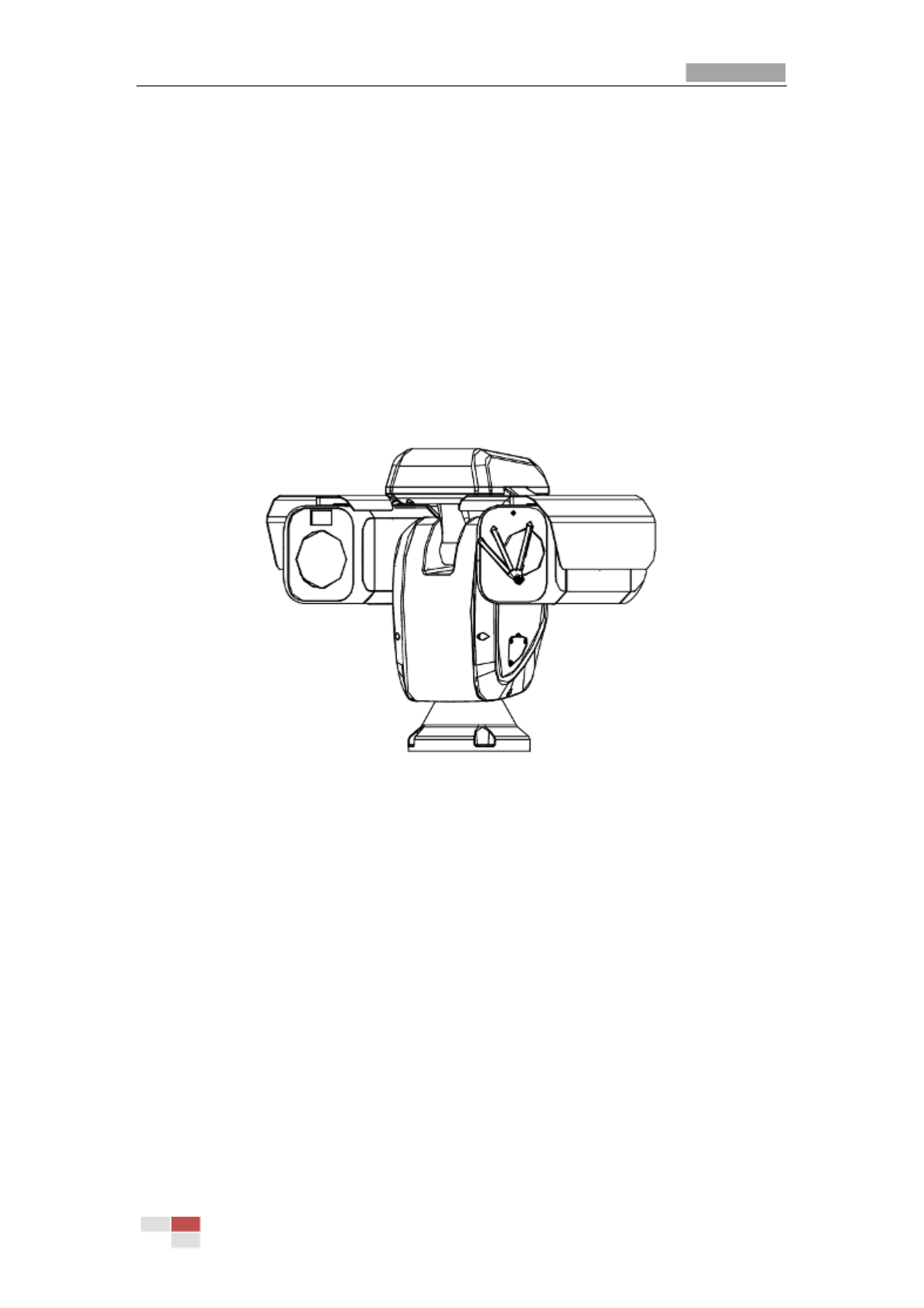
Therm -spectrum network positioning system (named as positioning system in the al bi
chapters below) integrates the function of the decoder, thermal camera, and the
high-definition zoom camera. It performs temperature measurement, dynamic fire source
detection and other smart detections in the remote surveillance of the power system,
metallurgy system, and petrochemical engineering, and so on.
You can get a high-quality live view via web browser or client software.
The figure below shows one type of the positioning system series.
Figure 1-1 Overview of Therm Positioning System al
1.2
1.2
1.2
1.21.2 System Requirement
System Requirement
System Requirement
System RequirementSystem Requirement
System requirement of web browser accessing is as follows:
Operating System
Operating System
Operating System
Operating SystemOperating System:
:
:
: : Microsoft Windows XP SP1 and above version / Vista / Win7 / Server
2003 / Server 2008 32bits
CPU:
CPU:
CPU:
CPU:CPU: Intel Pentium IV 3.0 GHz or higher
RAM:
RAM:
RAM:
RAM:RAM: 1G or higher
Display:
Display:
Display:
Display: Display: 1024× 768 resolution or higher
Web Browser:
Web Browser:
Web Browser:
Web Browser: Web Browser: Internet Explorer 8.0 and above version, Apple Safari 5.02 and above
version, Mozilla Firefox 5 and above version and Google Chrome 18 and above versions.
1.3
1.3
1.3
1.31.3 Functions
Functions
Functions
Functions Functions
The main functions of this camera is fire source detection, and temperature measurement,

User Manual of Thermal Network Positioning system
© Hikvision
2
and VCA (video content analysis) functions.
Fire Detection
Fire Detection
Fire Detection
Fire DetectionFire Detection
Fire Source Detection Shield enables you to shield certain areas from being detected
in fire source detection.
For fire detection, refer to Section 5.3 Fire
Section 5.3 Fire
Section 5.3 Fire
Section 5.3 Fire Section 5.3 Fire Source
Source
Source
Source Source Detection Config
Detection Config
Detection Config
Detection ConfigDetection Configuration
uration
uration
urationuration
.
Temperature Me
Temperature Me
Temperature Me
Temperature MeTemperature Measurement
asurement
asurement
asurement asurement
When you enable this function, it measures the actual temperature of the spot being
monitored. The device alarms when temperature exceeds the temperature threshold
value.
For temperature measurement, refer to Section 5.
Section 5.
Section 5.
Section 5.Section 5.4 Temperature Me
4 Temperature Me
4 Temperature Me
4 Temperature Me4 Temperature Measurement
asurement
asurement
asurementasurement.
VCA function
VCA function
VCA function
VCA functionVCA function
You can do intelligent analysis, such as behavior analysis. Multiple rules can be
configured for different requirements.
For VCA function, refer to Chapter 6
Chapter 6
Chapter 6
Chapter 6 Chapter 6

User Manual of Thermal Network Positioning system
© Hikvision
3
VCA
VCA
VCA
VCA VCA Configuration.
Alarm Input
Alarm Input
Alarm Input
Alarm Input Alarm Input and Output
and Output
and Output
and Output and Output
Refer to the figure below to configure the alarm devices and sensors.
Alarm Device /Alarm
Sensor?
Start
Alarm Device
(e.g., siren) Alarm Sensor (e.g.,
gas detector)
Connect to Alarm Output
Terminal (labeled ALARM OUT)
END
Connect your camera with the alarm device(s).
Connect to Alarm Input
Terminal (labeled ALARM IN)
Turn on the Camera. Turn on the Camera.
Go to Event>Basic Event>Alarm Output
and set the alarm.
Go to Event>Basic Event>Alarm Input
and set the alarm.
Set the schedule for the alarm device. Set the schedule for the sensor.
Link the alarm to e-mail,
center, alarm out , etc.
Set Alarm Linkage for events.
The functions vary depending on the models of positioning system.
Bi
Bi
Bi
BiBi-spectru
-spectru
-spectru
-spectru-spectrum
m
m
m m
The positioning system has two lens, an optical one and a thermal one, and two images
are respectively provided by each lens.
PTZ Limits
PTZ Limits
PTZ Limits
PTZ Limits PTZ Limits
The positioning system can be programmed to move within the PTZ limits (left/right,
up/down).
Scan Modes
Scan Modes
Scan Modes
Scan ModesScan Modes
The positioning system provides 5 scan modes: auto scan, tilt scan, frame scan, random
scan and panorama scan.
Presets
Presets
Presets
Presets Presets
A preset is a predefined image position. When the preset is called, the positioning system
will automatically move to the defined position. The presets can be added, modified,
deleted and called.
Label Display
Label Display
Label Display
Label Display Label Display
The on-screen label of the preset title, azimuth/elevation, zoom, time and positioning
system name can be displayed on the monitor. The displays of time and positioning

User Manual of Thermal Network Positioning system
© Hikvision
4
system name can be programmed.
Auto Flips
Auto Flips
Auto Flips
Auto FlipsAuto Flips
In manual tracking mode, when a target object goes directly beneath the positioning
system, the video will automatically flips 180 degrees in horizontal direction to maintain
continuity of tracking. This function can also be realized by auto mirror image depending
on different camera models.
Privacy Mask
Privacy Mask
Privacy Mask
Privacy MaskPrivacy Mask
This function allows you to block or mask certain area of a scene, for preventing the
personal privacy from recording or live viewing. A masked area will move with pan and tilt
functions and automatically adjust in size as the lens zooms telephoto and wide.
3D Positioning
3D Positioning
3D Positioning
3D Positioning3D Positioning
In the client software, use the left key of mouse to click on the desired position in the video
image and drag a rectangle area in the lower right direction, then the positioning system
will move the position to the center and allow the rectangle area to zoom in. Use the left
key of mouse to drag a rectangle area in the upper left direction to move the position to
the center and allow the rectangle area to zoom out.
Proportional Pan/T
Proportional Pan/T
Proportional Pan/T
Proportional Pan/TProportional Pan/Tilt
ilt
ilt
iltilt
Proportional pan/tilt automatically reduces or increases the pan and tilt speeds according
to the amount of zoom. At telephoto zoom settings, the pan and tilt speeds will be slower
than at wide zoom settings. This keeps the image from moving too fast on the live view
image when there is a large amount of zoom.
Auto Focus
Auto Focus
Auto Focus
Auto Focus Auto Focus
The auto focus enables the camera to focus automatically to maintain clear video images.
Day/Night Auto
Day/Night Auto
Day/Night Auto
Day/Night Auto Day/Night Auto Switch
Switch
Switch
Switch Switch
The positioning systems deliver color images during the day. And as light diminishes at
night, the positioning systems switch to night mode and deliver black and white images
with high quality.
Slow Shutter
Slow Shutter
Slow Shutter
Slow ShutterSlow Shutter
In slow shutter mode, the shutter speed will automatically slow down in low illumination
conditions to maintain clear video images by extending the exposure time. The feature
can be enabled or disabled.
Backlight Compe
Backlight Compe
Backlight Compe
Backlight CompeBacklight Compensation (
nsation (
nsation (
nsation (nsation (BLC)
BLC)
BLC)
BLC) BLC)
If you focus on an object against strong backlight, the object will be too dark to be seen
clearly. The BLC (Backlight Compensation) function can compensate light to the object in
the front to make it clear, but this causes the over-exposure of the background where the
light is strong.
Wide Dynamic Ra
Wide Dynamic Ra
Wide Dynamic Ra
Wide Dynamic RaWide Dynamic Range (
nge (
nge (
nge (nge (WDR)
WDR)
WDR)
WDR) WDR)
The wide dynamic range (WDR) function helps the camera provide clear images even
under back light circumstances. When there are both very bright and very dark areas
simultaneously in the field of view, WDR balances the brightness level of the whole image
and provide clear images with details.
White Balan
White Balan
White Balan
White BalanWhite Balance (WB)
ce (WB)
ce (WB)
ce (WB) ce (WB)
White balance can remove the unrealistic color casts. White balance is the white rendition
function of the camera to adjust the color temperature according to the environment

User Manual of Thermal Bi-spectrum Network Positioning System
© Hikvision
6
Chapter 2
Chapter 2
Chapter 2
Chapter 2Chapter 2
Network Connectio
Network Connectio
Network Connectio
Network ConnectioNetwork Connection
n
n
n n
Before you start:
Before you start:
Before you start:
Before you start:Before you start:
If you want to set the network positioning system via a LAN (Local Area Network),
please refer to Section 2.1.
Section 2.1.
Section 2.1.
Section 2.1.Section 2.1.
If you want to set the network positioning system via a WAN (Wide Area Network),
please refer to Section 2.2.
Section 2.2.
Section 2.2.
Section 2.2. Section 2.2.
2.1
2.1
2.1
2.12.1 Setting
Setting
Setting
Setting Setting the
the
the
the the Network
Network
Network
NetworkNetwork
Positioning
Positioning
Positioning
Positioning Positioning System
System
System
System System over
over
over
over over
the LAN
the LAN
the LAN
the LAN the LAN
Purpose:
Purpose:
Purpose:
Purpose: Purpose:
To view and configure the positioning system via a LAN, you need to connect the network
positioning system in the same subnet with your computer, and install the SADP or client
software to search and change the IP of the network positioning system.
For the detailed introduction of SADP, please refer to Appendix.
2.1.1
2.1.1
2.1.1
2.1.12.1.1 Wiring over the LAN
Wiring over the LAN
Wiring over the LAN
Wiring over the LAN Wiring over the LAN
The following figures show the two ways of cable connection of a network positioning
system and a computer:
Purpose:
Purpose:
Purpose:
Purpose: Purpose:
To test the network positioning system, you can directly connect the network
positioning system to the computer with a network cable as shown in Figure 2-1.
Refer to the Figure 2-2 to set the network positioning system over the LAN via a
switch or a router.
Network Cable
PT Camera
Figure 2-1 Connecting Directly

User Manual of Thermal Network Positioning system
© Hikvision
7
Network Cable
Switch or Router
PC
Network Cable
PT Camera
Figure 2-2 Connecting via a Switch or a Router
2.1.2
2.1.2
2.1.2
2.1.22.1.2 Activating the Positioning syst
Activating the Positioning syst
Activating the Positioning syst
Activating the Positioning systActivating the Positioning system
em
em
em em
Purpose:
Purpose:
Purpose:
Purpose: Purpose:
You are required to activate the positioning system first before you can use the
positioning system.
Activation via Web Browser, Activation via SADP, and Activation via client software are
supported. In the following sections, activation via web browser and SADP will be taken as
examples. You may refer to the user manual of the positioning system for the details of
activation via client software.
Activation via Web B
Activation via Web B
Activation via Web B
Activation via Web BActivation via Web Browser
rowser
rowser
rowser rowser
Steps:
Steps:
Steps:
Steps: Steps:
1. Power on the positioning system, and connect the positioning system to the network.
2. Input the IP address into the address bar of the web browser, and click to enter
Enter
Enter
Enter
EnterEnter
the activation interface.
The default IP address of the positioning system is 192.168.1.64.
Figure 2-3 Activation Interface(Web)
3. Create a password and input the password into the password field.

User Manual of Thermal Network Positioning system
© Hikvision
8
STRONG
STRONG
STRONG
STRONG STRONG PASSWOR
PASSWOR
PASSWOR
PASSWORPASSWORD
D
D
D D RECOMMEN
RECOMMEN
RECOMMEN
RECOMMENRECOMMENDED
DED
DED
DEDDED–We highly recommend you create a
strong password of your own choosing (Using a minimum of 8 characters, including
at least three of the following categories: upper case letters, lower case letters,
numbers, and special characters.) in order to increase the security of your product.
And we recommend you reset your password regularly, especially in the high
security system, resetting the password monthly or weekly can better protect your
product.
4. Confirm the password.
5. Click to activate the positioning system and enter the live view interface.
OK
OK
OK
OKOK
Activation via SADP
Activation via SADP
Activation via SADP
Activation via SADPActivation via SADP Software
Software
Software
Software Software
SADP software is used for detecting the online device, activating the device, and resetting
the password.
Get the SADP software from the supplied disk or the official website, and install the SADP
according to the prompts. Follow the steps to activate the positioning system.
.
.
. .
Steps:
Steps:
Steps:
Steps:Steps:
1. Run the SADP software to search the online devices.
2. Check the device status from the device list, and select an inactive device.
Select inacve device.
Input and conrm
password.
Figure 2-4 SADP Interface
3. Create a password and input the password in the password field, and confirm the
password.
STRONG PASS
STRONG PASS
STRONG PASS
STRONG PASSSTRONG PASSWORD REC
WORD REC
WORD REC
WORD RECWORD RECOMMENDED
OMMENDED
OMMENDED
OMMENDEDOMMENDED–We highly recommend you create a
strong password of your own choosing (Using a minimum of 8 characters,
including at least three of the following categories: upper case letters, lower case
letters, numbers, and special characters.) in order to increase the security of your
product. And we recommend you reset your password regularly, especially in the
high security system, resetting the password monthly or weekly can better protect
your product.
4. Click to save the password.
OK
OK
OK
OKOK

User Manual of Thermal Network Positioning system
© Hikvision
9
You can check whether the activation is completed on the popup window. If activation
failed, please make sure that the password meets the requirement and then try again.
5. Change the device IP address to the same subnet with your computer by either
modifying the IP address manually or checking the checkbox of Enable DHCP
Enable DHCP
Enable DHCP
Enable DHCPEnable DHCP.
Figure 2-5 Modify the IP Address
6. Input the password and click to activate your IP address modification.
Save
Save
Save
SaveSave
Activation via Client
Activation via Client
Activation via Client
Activation via ClientActivation via Client Software
Software
Software
Software Software
The client software is versatile video management software for multiple kinds of devices.
Get the client software from the supplied disk or the official website, and install the
software according to the prompts. Follow the steps to activate the camera.
Steps:
Steps:
Steps:
Steps: Steps:
1. Run the client software and the control panel of the software pops up, as shown in
the figure below.

User Manual of Thermal Network Positioning system
© Hikvision
10
Figure 2-6 Control Panel
2. Click to enter the Device Management interface, as shown in the
Device Management
Device Management
Device Management
Device ManagementDevice Management
figure below.
Figure 2-7 Device Management Interface
3. Check the device status from the device list, and select an inactive device.
4. Click to pop up the Activation interface.
Activate
Activate
Activate
ActivateActivate
5. Create a password and input the password in the password field, and confirm the
password.

User Manual of Thermal Network Positioning system
© Hikvision
11
STRONG
STRONG
STRONG
STRONG STRONG PASSWORD
PASSWORD
PASSWORD
PASSWORDPASSWORD
RECOMM
RECOMM
RECOMM
RECOMMRECOMMENDED
ENDED
ENDED
ENDEDENDED–We highly recommend you create a
strong password of your own choosing (Using a minimum of 8 characters,
including at least three of the following categories: upper case letters, lower case
letters, numbers, and special characters.) in order to increase the security of your
product. And we recommend you reset your password regularly, especially in the
high security system, resetting the password monthly or weekly can better protect
your product.
Figure 2-8 Activation Interface
6. Click to start activation.
OK
OK
OK
OKOK
7. Click to pop up the Network Parameter Modification interface, as
Modify
Modify
Modify
Modify Modify Netin
Netin
Netin
NetinNetinfo
fo
fo
fo fo
shown in the figure below.
Figure 2-9 Modifying the Network Parameters
8. Change the device IP address to the same subnet with your computer by either
modifying the IP address manually or checking the checkbox of Enable DHCP
Enable DHCP
Enable DHCP
Enable DHCPEnable DHCP.
9. Input the password to activate your IP address modification.

User Manual of Thermal Network Positioning system
© Hikvision
12
2.2
2.2
2.2
2.22.2 Setting the Network
Setting the Network
Setting the Network
Setting the NetworkSetting the Network Positioning system
Positioning system
Positioning system
Positioning system Positioning system over the
over the
over the
over the over the
WAN
WAN
WAN
WAN WAN
Purpose:
Purpose:
Purpose:
Purpose: Purpose:
This section explains how to connect the network positioning system to the WAN with a
static IP or a dynamic IP.
2.2.1
2.2.1
2.2.1
2.2.12.2.1 Static IP Connection
Static IP Connection
Static IP Connection
Static IP Connection Static IP Connection
Before you start:
Before you start:
Before you start:
Before you start:Before you start:
Please apply a static IP from an ISP (Internet Service Provider). With the static IP address,
you can connect the network positioning system via a router or connect it to the WAN
directly.
Connecting
Connecting
Connecting
Connecting Connecting the network positioni
the network positioni
the network positioni
the network positionithe network positioning system via
ng system via
ng system via
ng system viang system via a router
a router
a router
a router a router
Steps:
Steps:
Steps:
Steps: Steps:
1. Connect the network positioning system to the router.
2. Assign a LAN IP address, the subnet mask and the gateway. Refer to for
Section
Section
Section
Section Section 2.1.2
2.1.2
2.1.2
2.1.2 2.1.2
detailed IP address configuration of th positioning system. e
3. Save the static IP in the router.
4. Set port mapping, E.g., 80, 8000 and 554 ports. The steps for port mapping vary
depending on different routers. Please call the router manufacturer for assistance with
port mapping.
5. Visit the network positioning system through a web browser or the client software
over the internet.
Posioning
System
Network
Cable
Router with Stac IP
PC
Network
Cable
Network
Cable
Internet
Figure 2-10 Accessing the Positioning system through Router with Static IP
Connecting
Connecting
Connecting
Connecting Connecting the network positioni
the network positioni
the network positioni
the network positionithe network positioning system with
ng system with
ng system with
ng system with ng system with static IP directly
static IP directly
static IP directly
static IP directlystatic IP directly
You can also save the static IP in the positioning system and directly connect it to the
internet without using a router. Refer to for detailed IP address configuration
Section
Section
Section
Section Section 2.1.2
2.1.2
2.1.2
2.1.2 2.1.2
of the positioning system.

User Manual of Thermal Network Positioning system
© Hikvision
13
Posioning
System
PC
Network
Cable
Network
Cable
Internet
Figure 2- Accessing the Positioning system with Static IP Directly 11
2.2.2
2.2.2
2.2.2
2.2.22.2.2 Dynamic IP Connection
Dynamic IP Connection
Dynamic IP Connection
Dynamic IP Connection Dynamic IP Connection
Before you start:
Before you start:
Before you start:
Before you start:Before you start:
Please apply a dynamic IP from an ISP. With the dynamic IP address, you can connect the
network positioning system to a modem or a router.
Connecting the
Connecting the
Connecting the
Connecting theConnecting the network p
network p
network p
network p network positioning syste
ositioning syste
ositioning syste
ositioning systeositioning system via a
m via a
m via a
m via a m via a router
router
router
router router
Steps:
Steps:
Steps:
Steps: Steps:
1. Connect the network positioning system to the router.
2. In the positioning system, assign a LAN IP address, the subnet mask and the gateway.
Refer to Section 2.1.2
Section 2.1.2
Section 2.1.2
Section 2.1.2Section 2.1.2 for detailed LAN configuration.
3. In the router, set the PPPoE user name, password and confirm the password.
For your privacy and to better protect your system against security risks, we strongly
recommend the use of strong passwords for all functions and network devices. The
password should be something of your own choosing (using a minimum of 8
characters, including upper case letters, lower case letters, numbers and special
characters) in order to increase the security of your product.
Proper configuration of all passwords and other security settings is the responsibility of
the installer and/or end-user.
4. Set port mapping. E.g. 80, 8000 and 554 ports. The steps for port mapping vary
depending on different routers. Please call the router manufacturer for assistance with
port mapping.
5. Apply a domain name from a domain name provider.
6. Configure the DDNS settings in the setting interface of the router.
7. Visit the positioning system via the applied domain name.
Connecting
Connecting
Connecting
Connecting Connecting the network p
the network p
the network p
the network pthe network positioning syste
ositioning syste
ositioning syste
ositioning systeositioning system
m
m
m m a mode
a mode
a mode
a mode a modem
m
m
m m
via
via
via
viavia
Purpose:
Purpose:
Purpose:
Purpose: Purpose:
This positioning system supports the PPPoE auto dial-up function. The positioning system
gets a public IP address by ADSL dial-up after the positioning system is connected to a
modem. You need to configure the PPPoE parameters of the network positioning system.
Refer to Section 7.1.1 Configur
Section 7.1.1 Configur
Section 7.1.1 Configur
Section 7.1.1 ConfigurSection 7.1.1 Configuring PPPoE Set
ing PPPoE Set
ing PPPoE Set
ing PPPoE Seting PPPoE Setti
ti
ti
titi
ngs
ngs
ngs
ngsngs for detailed configuration.

User Manual of Thermal Network Positioning system
© Hikvision
14
Posioning
System
Network
Cable
Modem
PC
Network
Cable
Network
Cable
Internet
Figure 2- Accessing the Positioning system with Dynamic IP 12
The obtained IP address is dynamically assigned via PPPoE, so the IP address always
changes after rebooting the positioning system. To solve the inconvenience of the
dynamic IP, you need to get a domain name from the DDNS provider (E.g.
DynDns.com). Please follow below steps for normal domain name resolution and
private domain name resolution to solve the problem.
Normal Domain Name Resolution
Posioning
System
Network
Cable
Router with Stac IP
PC
Network
Cable
Network
Cable
Internet
(Port Mapping)
Domain Name
Resoluon Server
Figure 2- Normal Domain Name Resolution 13
Steps:
Steps:
Steps:
Steps: Steps:
1. Apply a domain name from a domain name provider.
2. Configure the DDNS settings in the DDNS Setting
DDNS Setting
DDNS Setting
DDNS Setting DDNS Settings
s
s
ss interface of the network positioning
system. Refer to Section 7.
Section 7.
Section 7.
Section 7.Section 7.1.1 Configuring
1.1 Configuring
1.1 Configuring
1.1 Configuring 1.1 Configuring DDNS
DDNS
DDNS
DDNS DDNS Settings
Settings
Settings
SettingsSettings for detailed configuration.
3. Visit the positioning system via the applied domain name.
Private Domain Name Resolution

User Manual of Thermal Network Positioning system
© Hikvision
15
Posioning
System
Network
Cable
Router with Stac IP
PC
Network
Cable
Network
Cable
Internet
(Port Mapping)
PC + IP Server + Staic IP
Figure 2- Private Domain Name Resolution 14
Steps:
Steps:
Steps:
Steps: Steps:
1. Install and run the IP Server software in a computer with a static IP.
2. Access the network positioning system through the LAN with a web browser or the
client software.
3. Enable DDNS and select IP Server as the protocol type. Refer to Sect
Sect
Sect
SectSection
ion
ion
ion ion 7.1.1
7.1.1
7.1.1
7.1.1 7.1.1
Configuring DDN
Configuring DDN
Configuring DDN
Configuring DDNConfiguring DDNS Settings
S Settings
S Settings
S SettingsS Settings for detailed configuration.
User Manual of Thermal Bi-spectrum Network Positioning System
© Hikvision
16
Chapter 3
Chapter 3
Chapter 3
Chapter 3Chapter 3
Access to the Network
Access to the Network
Access to the Network
Access to the Network Access to the Network
Positioning system
Positioning system
Positioning system
Positioning system Positioning system
3.1
3.1
3.1
3.13.1 Accessing by Web Br
Accessing by Web Br
Accessing by Web Br
Accessing by Web BrAccessing by Web Browsers
owsers
owsers
owsers owsers
Steps:
Steps:
Steps:
Steps: Steps:
1. Open the web browser.
2. In the address field, input the IP address of the network positioning system, e.g.,
192.168.1.64 and press the key to enter the login interface.
Enter
Enter
Enter
EnterEnter
3. Activate the positioning system for the first time using, refer to the section
section
section
section section 1.2
1.2
1.2
1.2 1.2
2.
2.
2.
2.2.
Activating the Positio
Activating the Positio
Activating the Positio
Activating the PositioActivating the Positioning system
ning system
ning system
ning systemning system.
4. Select English as the interface language on the top-right of login interface.
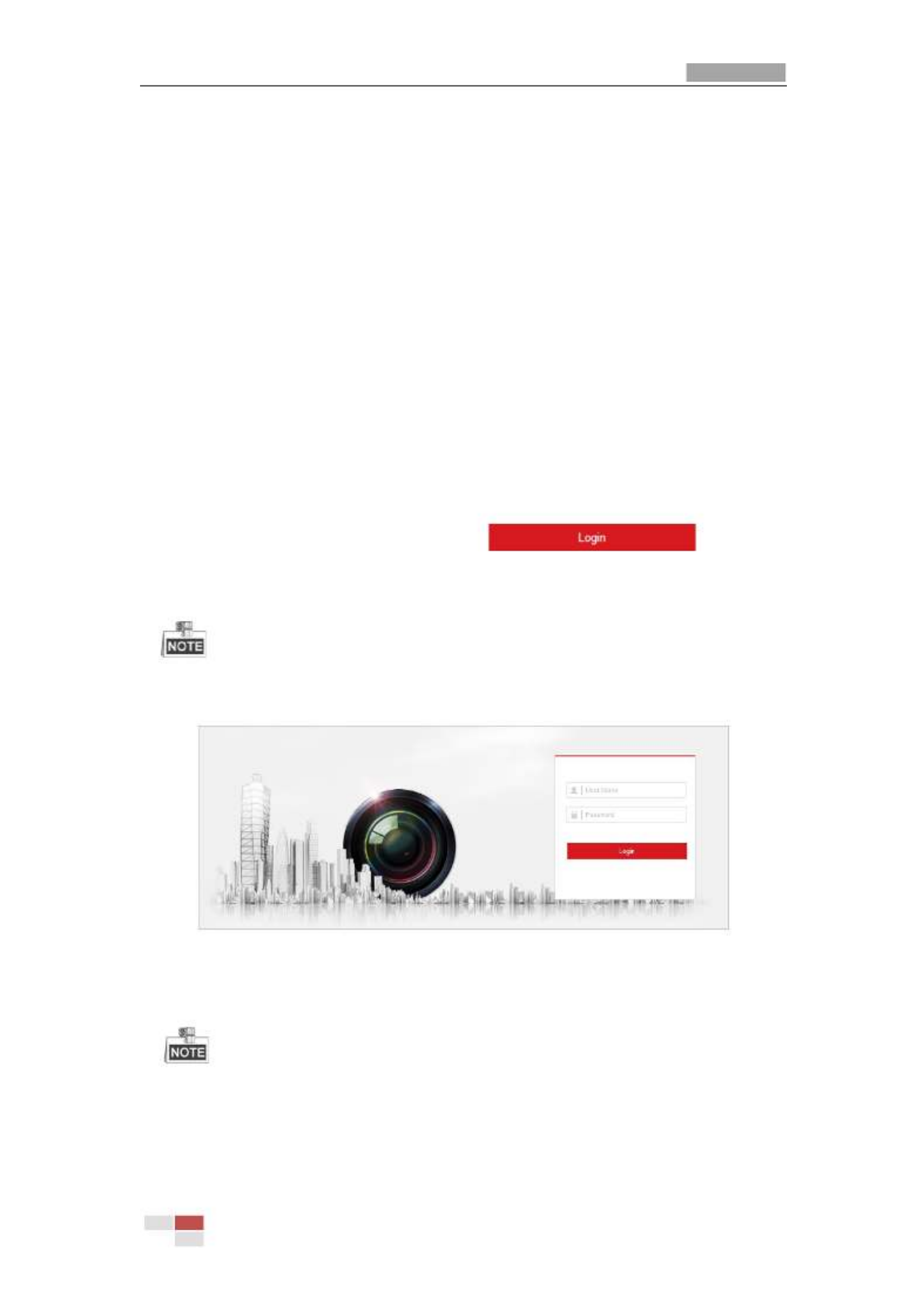
5. Input the user name and password and click .
The admin user should configure the device accounts and user/operator permissions
properly. Delete the unnecessary accounts and user/operator permissions.
The device IP address gets locked if the admin user performs 7 failed password
attempts (5 attempts for the user/operator).
Figure 3-1 Login Interface
6. Install the plug-in before viewing the live video and operating the positioning system.
Please llow the installation prompts to install the plug- . fo in
You may have to close the web browser to install the plug-in. Please reopen the web
browser and log in again after installing the plug-in.
User Manual of Thermal Network Positioning system
© Hikvision
17
Figure 3-2 Download and Install Plug- in
3.2
3.2
3.2
3.23.2 Accessing by Client
Accessing by Client
Accessing by Client
Accessing by ClientAccessing by Client Software
Software
Software
Software Software
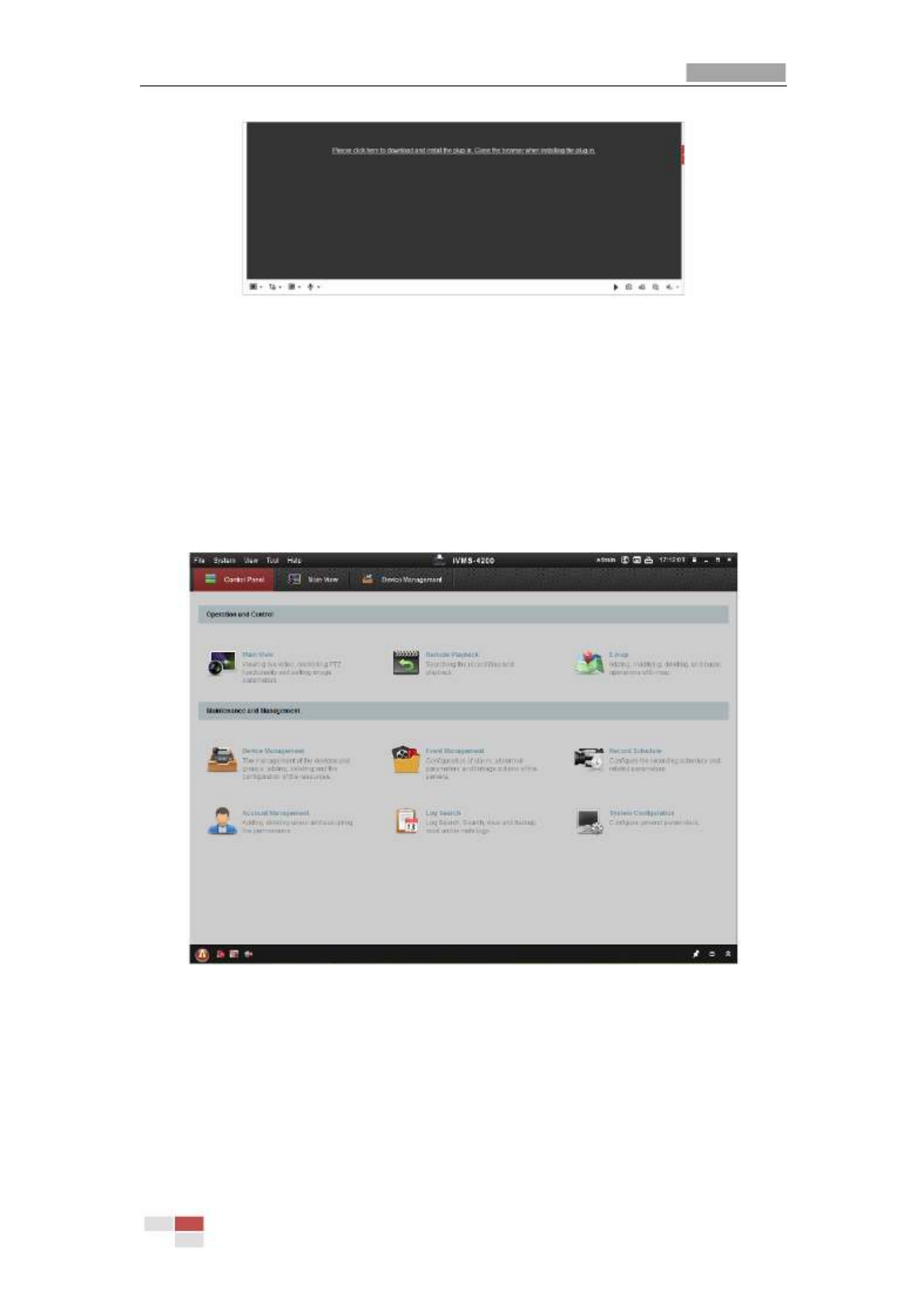
The product CD contains the client software. You can view the live video and manage the
positioning system with the client software.
Follow the installation prompts to install the client software and WinPcap. The
configuration interface and live view interface of client software are shown bel . ow
Figure 3-3 iVMS-4200 Control Panel

User Manual of Thermal Network Positioning system
© Hikvision
18
Figure 3-4 iVMS-4200 Live View Interface
If you use third party VMS software, please contact technical support of our branch
for camera firmware.
For detailed information about client software of our company, please refer to the
user manual of the software. This manual mainly introduces accessing to the network
positioning system by web browser.

User Manual of Thermal Bi-spectrum Network Positioning System
© Hikvision
19
Chapter 4
Chapter 4
Chapter 4
Chapter 4Chapter 4
Basic Operations
Basic Operations
Basic Operations
Basic Operations Basic Operations
In this and the following chapters, operation of the positioning system by the web browser
will be taken as an example.
4.1
4.1
4.1
4.14.1 Configuring Local Parameters
Configuring Local Parameters
Configuring Local Parameters
Configuring Local ParametersConfiguring Local Parameters
The local configuration refers to the parameters of the live view and other operations
using the web browser.
Steps:
Steps:
Steps:
Steps: Steps:
1. Enter the Local Configuration interface:
Configuration
Configuration
Configuration
Configuration Configuration > Local
> Local
> Local
> Local> Local
Figure 4-1 Local Configuration Interface
2. Configure the following settings:
Live
Live
Live
Live Live View
View
View
View View Parameters:
Parameters:
Parameters:
Parameters: Parameters: Set the protocol type, play performance, rules and image

User Manual of Thermal Network Positioning system
© Hikvision
20
format.
Protocol Type:
Protocol Type:
Protocol Type:
Protocol Type:Protocol Type: TCP, UDP, MULTICAST and HTTP are selectable.
TCP:
TCP:
TCP:
TCP:TCP: Ensures complete delivery of streaming data and better video quality, yet the
real-time transmission will be affected.
UDP:
UDP:
UDP:
UDP:UDP: Provides real-time audio and video streams.
MULTICAST:
MULTICAST:
MULTICAST:
MULTICAST:MULTICAST: It’s recommended to select the protocol type to when
MULTICAST
MULTICAST
MULTICAST
MULTICASTMULTICAST
using the Multicast function.
HTTP:
HTTP:
HTTP:
HTTP:HTTP: Allows the same quality as of TCP without setting specific ports for
streaming under some network environments.
Play Performa
Play Performa
Play Performa
Play PerformaPlay Performance:
nce:
nce:
nce:nce: Set the play performance to Shortest Delay, or Auto.
Rules:
Rules:
Rules:
Rules: Rules: It refers to the rules on your local browser, select enable or disable to
display or not display the colored marks when the motion detection, fire detection,
or intrusion detection is triggered. E.g., enabled as the rules are, and the fire
detection is enabled as well, when a fire is detected, it will be marked with a green
rectangle on the live view.
Image Format:
Image Format:
Image Format:
Image Format:Image Format: The captured pictures can be saved as different format. JPEG and
BMP are available.
Fire Point: Locate
Fire Point: Locate
Fire Point: Locate
Fire Point: Locate Fire Point: Locate Highest Te
Highest Te
Highest Te
Highest TeHighest Temperature Point
mperature Point
mperature Point
mperature Pointmperature Point, and Fra
Fra
Fra
FraFrame Fire Point
me Fire Point
me Fire Point
me Fire Pointme Fire Point are selectable.
Display the highest temperature area as point or frame.
Display Temperat
Display Temperat
Display Temperat
Display TemperatDisplay Temperature Info.:
ure Info.:
ure Info.:
ure Info.: ure Info.: Display temperature information or not with
temperature measurement rule configured.
Display Tempe
Display Tempe
Display Tempe
Display TempeDisplay Temperature Info. on
rature Info. on
rature Info. on
rature Info. on rature Info. on Capture:
Capture:
Capture:
Capture: Capture: Display temperature information on the
capture or not.
Record File Set
Record File Set
Record File Set
Record File SetRecord File Settings:
tings:
tings:
tings:tings: Set the saving path of the video files.
Record
Record
Record
Record Record File
File
File
File File Size:
Size:
Size:
Size: Size: Select the packed size of manually recorded and downloaded
video files. The size can be set to 256M, 512M or 1G.
Save record file
Save record file
Save record file
Save record fileSave record files to:
s to:
s to:
s to: s to: Set the saving path for the manually recorded video files.
Save
Save
Save
Save Save downl
downl
downl
downldownloaded
oaded
oaded
oaded oaded files
files
files
files files to:
to:
to:
to: to: Set the saving path for the downloaded video files in
interface.
Picture
Picture
Picture
Picture Picture and
and
and
and and Clip
Clip
Clip
Clip Clip Settings:
Settings:
Settings:
Settings: Settings: Set the saving paths of the captured pictures and clipped
video files.
Save
Save
Save
Save Save snaps
snaps
snaps
snapssnapshots
hots
hots
hots hots in
in
in
in in live
live
live
live live view
view
view
view view to:
to:
to:
to:to: Set the saving path of the manually captured
pictures in interface.
Save snapshots when playback to:
Save snapshots when playback to:
Save snapshots when playback to:
Save snapshots when playback to: Save snapshots when playback to: Set the saving path of the captured pictures in
interface.
Save
Save
Save
Save Save clips
clips
clips
clips clips to:
to:
to:
to: to: Set the saving path of the clipped video files in
interface.
You can click to change the directory for saving video files, clips and
Browse
Browse
Browse
Browse Browse

User Manual of Thermal Network Positioning system
© Hikvision
21
pictures.
You can click Open
Open
Open
OpenOpen to directly open the video files, clips and pictures.
3. Click to save the settings.
4.2
4.2
4.2
4.24.2 Live View Page
Live View Page
Live View Page
Live View Page Live View Page
Purpose:
Purpose:
Purpose:
Purpose: Purpose:
The live video page allows you to view live video, capture images, realize PTZ control,
set/call presets and configure video parameters.
Log in the network positioning system to enter the live view page, or you can click
on the menu bar of the main page to enter the live view page.
Descriptions of
Descriptions of
Descriptions of
Descriptions of Descriptions of the live view pa
the live view pa
the live view pa
the live view pathe live view page:
ge:
ge:
ge: ge:
Live View
Parameters
Live View Window
Toolbar
Show or hide
PTZ control
panel
PTZ Control
Preset/Patrol/Pattern
Menu Bar
Figure 4-2 Live View Page
Menu Bar:
Menu Bar:
Menu Bar:
Menu Bar:Menu Bar:
Click each tab to enter Live View, Playback, Picture, and Configuration page respectively.
Click to display the help file of the positioning system.
Click to logout the system.
Live View Windo
Live View Windo
Live View Windo
Live View WindoLive View Window:
w:
w:
w: w:
Display the live video.
Toolbar:
Toolbar:
Toolbar:
Toolbar:Toolbar:
Operations on the live view page, e.g., live view, capture, record, audio on/off, regional
exposure, regional focus, etc.

User Manual of Thermal Network Positioning system
© Hikvision
22
PTZ Control:
PTZ Control:
PTZ Control:
PTZ Control: PTZ Control:
Panning, tilting, focusing and zooming actions of the positioning system. The lighter, wiper,
one-touch focus and lens initialization control.
Preset/patrol/patt
Preset/patrol/patt
Preset/patrol/patt
Preset/patrol/pattPreset/patrol/pattern:
ern:
ern:
ern: ern:
Set and call the preset/patrol/pattern for the positioning system.
Pattern function varies depending on the models of positioning system.
Live View P
Live View P
Live View P
Live View PLive View Parameters:
arameters:
arameters:
arameters:arameters:
Configure the image size, stream type, plug-in type, and two-way audio of the live video.
4.3
4.3
4.3
4.34.3 Starting Live View
Starting Live View
Starting Live View
Starting Live View Starting Live View
In the live view window as shown in Figure 4-3, click on the toolbar to start the live
view of the positioning system.
Figure 4-3 Start Live View
4.3.1
4.3.1
4.3.1
4.3.14.3.1 Toolbar Description
Toolbar Description
Toolbar Description
Toolbar Description Toolbar Description
Table 4-1 Descriptions of the Toolbar
Icon
Icon
Icon
Icon Icon
Descriptio
Descriptio
Descriptio
DescriptioDescription
n
n
n n
Icon
Icon
Icon
Icon Icon
Descriptio
Descriptio
Descriptio
DescriptioDescription
n
n
n n
/
Start/Stop Live view.
Manually capture the
pictures.
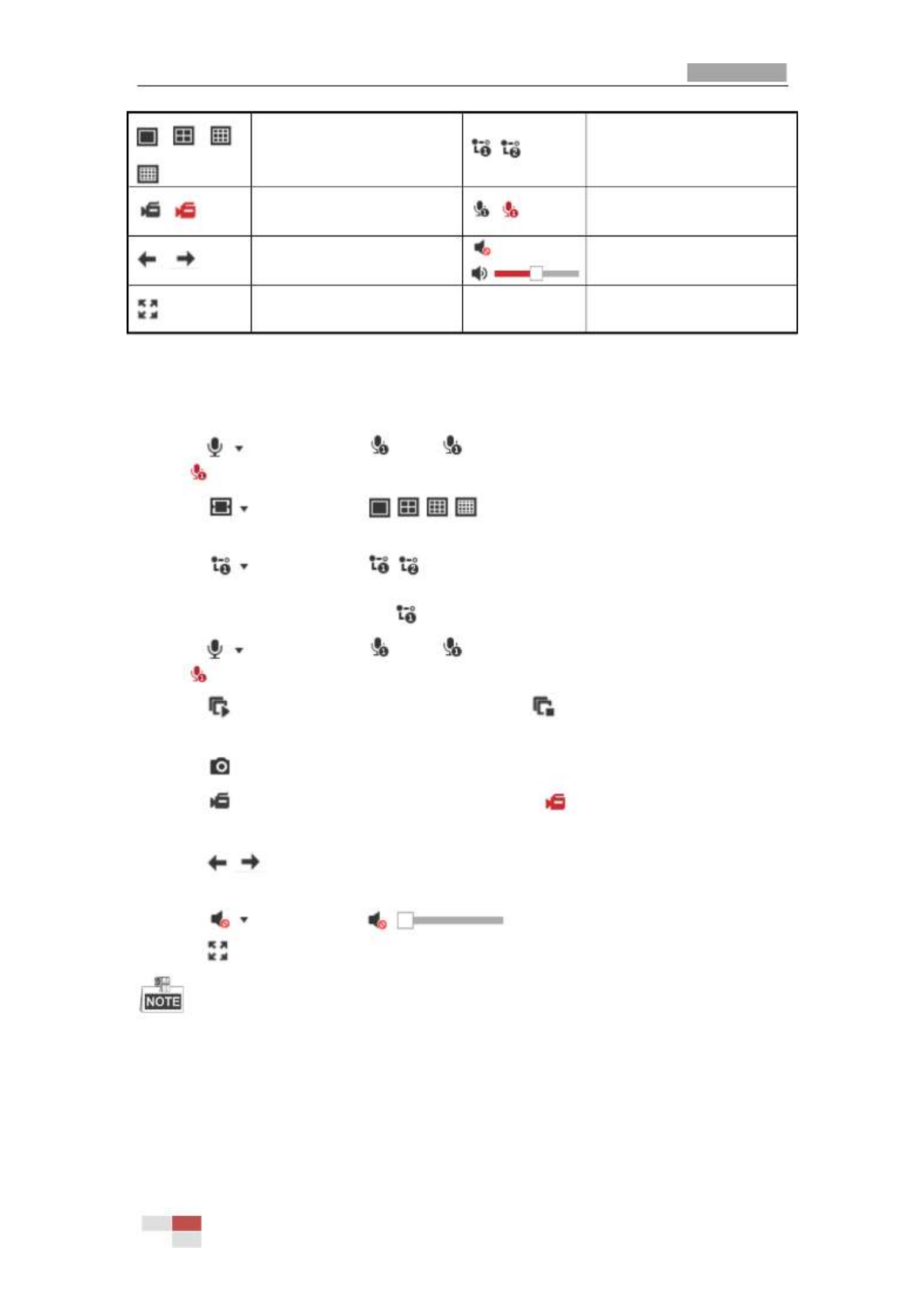
User Manual of Thermal Network Positioning system
© Hikvision
23
/ / /
Display in 1× 1/2× 2/3× 3/4× 4
window.
/
Live view with the main/sub
stream.
/
Manual start/stop
recording.
/
Start/Stop Two-way Audio.
/
View previous / next page.
/
Mute/Audio on and adjust
volume
Show full screen
Double-click on the live video to switch the current live view into full-screen or return to
normal mode from the full-screen.
Click and it displays . Click to enable two-way audio and the icon turns
into . Click the icon again to stop two-way audio.
Click to select from and display live video in/ / / 1 × 1/2 × 2/3 × 3/4
× 4 window.
Click to select from and display live video with the main/ sub stream. /
The main stream is with a relatively high resolution and needs much bandwidth. The
default setting of stream type is .
Click and it displays . Click to enable two-way audio and the icon turns
into . Click the icon again to stop two-way audio.
Click to start live view and the icon turns into . Click the icon again to stop
live view.
Click to capture the picture.
Click to start recording and the icon turns into . Click the icon again to stop
recording.
Click to switch between the optical channel and thermal channel when
selecting 1 × 1 live view window.
Click to display the . Drag the slider to adjust the volume.
Click to show full screen of live view, press Esc to exit.
Before using the two-way audio or recording with a functionsudio , please set the Strea
Strea
Strea
StreaStream
m
m
m m
Type
Type
Type
TypeType to Video
Video
Video
Video Video & Audio
& Audio
& Audio
& Audio& Audio referring to Section
Section
Section
Section Section 7.2.1 Configur
7.2.1 Configur
7.2.1 Configur
7.2.1 Configur7.2.1 Configuring Video Settings
ing Video Settings
ing Video Settings
ing Video Settingsing Video Settings.
Please refer to the following sections for more information:
Configuring remote recording in Section 5.1.1 Configu
Section 5.1.1 Configu
Section 5.1.1 Configu
Section 5.1.1 ConfiguSection 5.1.1 Configuring Recording Sc
ring Recording Sc
ring Recording Sc
ring Recording Scring Recording Schedule
hedule
hedule
hedulehedule.
Setting the image quality of the live video in Section 7.4 Configur
Section 7.4 Configur
Section 7.4 Configur
Section 7.4 ConfigurSection 7.4 Configuring Image S
ing Image S
ing Image S
ing Image Sing Image Settings.
ettings.
ettings.
ettings. ettings.
and
Section
Section
Section
SectionSection 7.2.1 Co
7.2.1 Co
7.2.1 Co
7.2.1 Co7.2.1 Configuring Video S
nfiguring Video S
nfiguring Video S
nfiguring Video Snfiguring Video Settings
ettings
ettings
ettingsettings.
Setting the OSD text on live video i n Section
Section
Section
SectionSection 7.4.2 Co
7.4.2 Co
7.4.2 Co
7.4.2 Co7.4.2 Configuring
nfiguring
nfiguring
nfiguring nfiguring OSD Settings
OSD Settings
OSD Settings
OSD SettingsOSD Settings.

User Manual of Thermal Network Positioning system
© Hikvision
24
4.4
4.4
4.4
4.44.4 Operating PTZ Control
Operating PTZ Control
Operating PTZ Control
Operating PTZ ControlOperating PTZ Control
Purpose:
Purpose:
Purpose:
Purpose: Purpose:
In the live view interface, you can use the PTZ control buttons to control panning, tilting
and zooming.
4.4.1
4.4.1
4.4.1
4.4.14.4.1 PTZ Control Panel
PTZ Control Panel
PTZ Control Panel
PTZ Control Panel PTZ Control Panel
On the live view page, click to show the PTZ control panel or click to hide it.
Click the direction buttons to control the pan/tilt movements.
Click the zoom/iris/focus buttons to realize lens control.
Figure 4-4 PTZ Control Panel
Table 4-2 Descriptions of PTZ Control Panel
Button
Button
Button
Button Button
Name
Name
Name
Name Name
Description
Description
Description
Description Description

User Manual of Thermal Network Positioning system
© Hikvision
25
Button
Button
Button
Button Button
Name
Name
Name
Name Name
Description
Description
Description
Description Description
PTZ Control Panel
Hold and press the direction
button to pan/tilt the positioning
system.
Click and the positioning
system keeps panning, the icon
turns into . Click the icon again
to stop the positioning system.
Zoom out/in
Click , the lens zooms in, click
, and the lens zooms out.
Focus near/far
Click , the lens focus far and
the items far away gets clear.
Click , the lens focus near and
the items nearby gets clear.
Iris close/open
When the image is too dark, click
to open the iris. When the
image is too bright, click to
close the iris.
Auxiliary Functions
The auxiliary functions include
light, wiper, auxiliary focus, lens
initialization, manual tracking, 3D
positioning, de-icing heater,
click- -thermometry, synchronize to
FOV
Speed Adjustment
Adjust speed of pan/tilt
movements.
Preset
Refer to 4.4.3
4.4.3
4.4.3
4.4.34.4.3 for detailed
information of setting preset.
Patrol
Refer to 4.4.4
4.4.4
4.4.4
4.4.44.4.4 for detailed
information of setting patrol.
Pattern
Refer to for detailed
4.4.6
4.4.6
4.4.6
4.4.64.4.6
information of setting pattern.
Buttons on the
Buttons on the
Buttons on the
Buttons on theButtons on the Preset/Pa
Preset/Pa
Preset/Pa
Preset/Pa Preset/Patrol/Patterns inte
trol/Patterns inte
trol/Patterns inte
trol/Patterns intetrol/Patterns interface:
rface:
rface:
rface: rface:
Table 4-3 Descriptions of Buttons
Buttons
Buttons
Buttons
ButtonsButtons
Description
Description
Description
DescriptionDescription
Start the selected patrol/pattern.

User Manual of Thermal Network Positioning system
© Hikvision
26
Stop current patrol/pattern.
Set the selected preset/patrol.
Delete the selected preset/patrol/pattern.
Start recording a pattern.
Stop recording the pattern.
4.4.2
4.4.2
4.4.2
4.4.24.4.2 Auxiliary Functions
Auxiliary Functions
Auxiliary Functions
Auxiliary Functions Auxiliary Functions
The Auxiliary functions panel is shown in the figure below:
Figure 4-5 Auxiliary Functions
Light
Click to enable/disable the light supplement of the positioning system. This
function is reserved.
Wiper
Click to move the wiper once.
Auxiliary Focus
The auxiliary focus function is reserved.
Click and the lens operates the movements for initialization.
Click to enable manual De-Icing function of the device.
The de-icing function takes effect when the device inner temperature is ≤ 30°C (86°F).
Click to enable/disable the manual thermometry function of the device. You can
click any position on the interface to show the real temperature.
Click to synchronize the FOV of optical lens and thermal lens
Manual Tracking
Before you start:
Before you start:
Before you start:
Before you start:Before you start:
Go to Configuration
Configuration
Configuration
Configuration Configuration >
>
>
> > System
System
System
System System >
>
>
> > Maintenan
Maintenan
Maintenan
MaintenanMaintenance
ce
ce
ce ce >
>
>
> > VCA
VCA
VCA
VCA VCA Resource
Resource
Resource
Resource Resource Type
Type
Type
TypeType and select the VCA

User Manual of Thermal Network Positioning system
© Hikvision
27
Resource as Temperature Me
Temperature Me
Temperature Me
Temperature MeTemperature Measurement +
asurement +
asurement +
asurement + asurement + Behavior Analysi
Behavior Analysi
Behavior Analysi
Behavior AnalysiBehavior Analysis
s
s
ss.
Then enter the VCA Information Configuration interface:
Configuration
Configuration
Configuration
Configuration Configuration > VCA Configura
> VCA Configura
> VCA Configura
> VCA Configura> VCA Configuration > VCA Info
tion > VCA Info
tion > VCA Info
tion > VCA Infotion > VCA Info and enable Intelligent Analysis first.
Steps:
Steps:
Steps:
Steps: Steps:
1. Click on the toolbar of live view interface.
2. Click a moving object in the live video.
The positioning system will track the object automatically.
3D Positioning
Steps:
Steps:
Steps:
Steps: Steps:
1. Click on the toolbar of live view interface.
2. Operate the 3D positioning function:
3. Click a position of the live video. The corresponding position will be moved to the
center of the live video.
4. Hold down the left mouse button and drag the mouse to the lower right on the live
video. The corresponding position will be moved to the center of the live video and
zoomed in.
5. Hold down the left mouse button and drag the mouse to the upper left on the live
video. The corresponding position will be moved to the center of the live video and
zoomed out.
One-touch Patrol
Click to call one-touch patrol. For detailed information of setting one-touch
patrol, refer to 4.4.5 One-to
4.4.5 One-to
4.4.5 One-to
4.4.5 One-to4.4.5 One-touch Patrol
uch Patrol
uch Patrol
uch Patroluch Patrol.
One-touch Park
Click to save the current view as the preset No. 32 and start park at the the
current position. This function is reserved.
4.4.3
4.4.3
4.4.3
4.4.34.4.3 Setting / Calling a Preset
Setting / Calling a Preset
Setting / Calling a Preset
Setting / Calling a PresetSetting / Calling a Preset
Purpose:
Purpose:
Purpose:
Purpose: Purpose:
A preset is a predefined image position. For the defined preset, you can click the calling
button to quickly view the desired image position.
Setting a P
Setting a P
Setting a P
Setting a PSetting a Preset:
reset:
reset:
reset: reset:
Steps:
Steps:
Steps:
Steps: Steps:
1. In the PTZ control panel, select a preset number from the preset list.

User Manual of Thermal Network Positioning system
© Hikvision
28
Figure 4-6 Setting a Preset
2. Use the PTZ control buttons to move the lens to the desired position.
• Pan the positioning system to the right or left.
• Tilt the positioning system up or down.
• Zoom in or out.
• Refocus the lens.
3. Click to finish the setting of the current preset.
4. Edit a preset name by double clicking on the default name such as preset 1. (The pre-defined presets
are named already and not configurable. Please refer to the user manual for detailed function
description.)
5. You can click to delete the preset.
You can configure up to 256 presets.
Calling a P
Calling a P
Calling a P
Calling a PCalling a Preset:
reset:
reset:
reset: reset:
In the PTZ control panel, select a defined preset from the list and click to call the
preset.
Figure 4-7 Calling a Preset
For convenient preset selection, refer to the following steps to navigate to the preset you
want.
Steps:
Steps:
Steps:
Steps: Steps:
1. Select any preset from the list.
2. Click the preset number you need on the keyboard.
The following presets are predefined with special commands. You can only call them
but not congure them. For instance, preset 99 is the “Start auto scan”. If you call the

User Manual of Thermal Network Positioning system
© Hikvision
29
preset 99, the positioning system starts auto scan function.
Pattern function varies depending on the models of positioning system .
Table 4-4 Special Presets
Preset
Preset
Preset
Preset Preset
Function
Function
Function
Function Function
Preset
Preset
Preset
Preset Preset
Function
Function
Function
Function Function
33
Auto flip
92
Start to set limit stops
34
Back to initial position
93
Set limit stops manually
35
Call patrol 1
94
Remote reboot
36
Call patrol 2
95
Call OSD menu
37
Call patrol 3
96
Stop a scan
38
Call patrol 4
97
Start random scan
39
Day mode (IR cut filter in)
98
Start frame scan
40
Night mode (IR cut filter out)
99
Start auto scan
41
Call pattern 1
100
Start tilt sc an
42
Call pattern 2
101
Start panorama scan
43
Call pattern 3
102
Call patrol 5
44
Call pattern 4
103
Call patrol 6
45
One-touch Patrol
104
Call patrol 7
90
Wiper
105
Call patrol 8
Figure 4-8 Special Preset
You may need to use the OSD (On Screen Display) menu when controlling the
positioning system remotely. To display the OSD menu on the live view screen, you
can call the preset number 95.

User Manual of Thermal Network Positioning system
© Hikvision
30
4.4.4
4.4.4
4.4.4
4.4.44.4.4 Setting / Calling a Patrol
Setting / Calling a Patrol
Setting / Calling a Patrol
Setting / Calling a PatrolSetting / Calling a Patrol
Purpose:
Purpose:
Purpose:
Purpose: Purpose:
A patrol is a memorized series of preset function. It can be configured and called on the
patrol settings interface. There are up to 8 patrols for customizing. A patrol can be
configured with 32 presets.
Before you start:
Before you start:
Before you start:
Before you start:Before you start:
Please make sure that the presets you want to add into a patrol have been defined.
Setting a P
Setting a P
Setting a P
Setting a PSetting a Patrol:
atrol:
atrol:
atrol: atrol:
Steps:
Steps:
Steps:
Steps: Steps:
1. In the PTZ control panel, click to enter the patrol settings interface.
2. Select a patrol number from the list and click .
3. Click to enter the adding interface of preset, as shown in Figure 4-9.
Figure 4-9 Adding Presets
4. Configure the preset number, patrol time and patrol speed.
Name
Name
Name
Name Name
Description
Description
Description
Description Description
Patrol Time
It is the duration staying on one patrol point. The positioning
system moves to another patrol point after the patrol time.
Patrol Speed
It is the speed of moving from one preset to another.
5. Click to save a preset into the patrol.
OK
OK
OK
OKOK
6. Repeat the steps from 3 to 5 to add more presets.
7. Click to save all the patrol settings.
OK
OK
OK
OKOK
Calling a Patrol:
Calling a Patrol:
Calling a Patrol:
Calling a Patrol:Calling a Patrol:
In the PTZ control panel, select a defined patrol from the list and click to call the patrol,
as shown in Figure 4- . 10

User Manual of Thermal Network Positioning system
© Hikvision
31
Figure 4-10 Calling a Preset
4.4.5
4.4.5
4.4.5
4.4.54.4.5 One-touch Patrol
One-touch Patrol
One-touch Patrol
One-touch Patrol One-touch Patrol
Purpose:
Purpose:
Purpose:
Purpose: Purpose:
One-touch patrol is an automatically created patrol. The system automatically add preset
No.1 to No.32 to the patrol path 8. You can call the one-touch patrol and the positioning
system moves as the patrol path 8 automatically.
Steps:
Steps:
Steps:
Steps: Steps:
1. Set preset No.1 to No.32. Refer to 4.4.3 Setting / Calli
4.4.3 Setting / Calli
4.4.3 Setting / Calli
4.4.3 Setting / Calli4.4.3 Setting / Calling a Preset
ng a Preset
ng a Preset
ng a Presetng a Preset for detailed
information of setting preset.
2. Call preset No. 45, and the positioning system moves as patrol path 8.
3. Click to enter the patrol settings interface and start/stop one-touch patrol, edit
the patrol time and the speed.
4. You can click of the PTZ control panel to start one-touch patrol.
Figure 4- Patrol Path 8 11

User Manual of Thermal Network Positioning system
© Hikvision
32
4.4.6
4.4.6
4.4.6
4.4.64.4.6 Setting / Calling a Patt
Setting / Calling a Patt
Setting / Calling a Patt
Setting / Calling a PattSetting / Calling a Pattern
ern
ern
ern ern
Purpose:
Purpose:
Purpose:
Purpose: Purpose:
A pattern is a memorized series of pan, tilt, zoom, and preset functions. It can be called on
the pattern settings interface. There are up to 4 patterns for customizing.
Pattern function varies depending on positioning system models.
Setting a P
Setting a P
Setting a P
Setting a PSetting a Pattern:
attern:
attern:
attern: attern:
Steps:
Steps:
Steps:
Steps: Steps:
1. In the PTZ control panel, click to enter the pattern settings interface.
2. Select a pattern number from the list as shown in Figure 4- . 12
Figure 4- Patterns Settings Interface 12
3. Click to enable recording the panning, tilting and zooming actions.
4. Use the PTZ control buttons to move the lens to the desired position after the
information of PROGRAM
PROGRAM
PROGRAM
PROGRAM PROGRAM PATTERN R
PATTERN R
PATTERN R
PATTERN RPATTERN REMAINNING
EMAINNING
EMAINNING
EMAINNING EMAINNING MEMORY
MEMORY
MEMORY
MEMORYMEMORY(%)
(%)
(%)
(%)(%) is displayed on the
screen.
Pan the positioning system to the right or left.
Tilt the positioning system up or down.
Zoom in or out.
Refocus the lens.
5. Click to save all the pattern settings.
Buttons on the
Buttons on the
Buttons on the
Buttons on theButtons on the Patterns inte
Patterns inte
Patterns inte
Patterns inte Patterns interface:
rface:
rface:
rface: rface:
Buttons
Buttons
Buttons
ButtonsButtons
Description
Description
Description
DescriptionDescription
Start the selected patrol/pattern.
Stop current patrol/pattern.
Set the selected preset/patrol.
Delete the selected preset/patrol/pattern.
Start recording a pattern.

User Manual of Thermal Network Positioning system
© Hikvision
33
Stop recording the pattern.
These 4 patterns can be operated separately and with no priority level.
When configuring and calling the pattern, proportional pan is valid; the limit stops and
auto flip will be invalid; and the 3D positioning operation is not supported.
4.5
4.5
4.5
4.54.5 Playback
Playback
Playback
Playback Playback
Purpose:
Purpose:
Purpose:
Purpose: Purpose:
This section explains how to view the video files stored in the network disks or memory
cards.
4.5.1
4.5.1
4.5.1
4.5.14.5.1 Play Back Video Files
Play Back Video Files
Play Back Video Files
Play Back Video FilesPlay Back Video Files
Steps:
Steps:
Steps:
Steps: Steps:
1. Click on the menu bar to enter playback interface.
Figure 4- Playback Interface 13
2. Select the date and click .

User Manual of Thermal Network Positioning system
© Hikvision
34
Figure 4- Search Video 14
3. Click to play the video files found on this date.
The toolbar on the bottom of Playback interface can be used to control playing process.
Figure 4- Playback Toolbar 15

User Manual of Thermal Network Positioning system
© Hikvision
35
Table 4-5 Description of the buttons
Button
Button
Button
ButtonButton
Operation
Operation
Operation
OperationOperation
Button
Button
Button
ButtonButton
Operation
Operation
Operation
OperationOperation
Play
Capture a picture
Pause
/
Start/Stop clipping
video files
Stop
/
Audio on and
adjust
volume/Mute
Speed down
Download
Speed up
Playback by frame
/ / /
Display in
1× 1/2× 2/3× 3/4× 4
window.
Show full screen
Stop all Playback
Play recorded
videos of different
cameras
asynchronously.
Play recorded
videos of different
cameras
synchronously.
You can choose the file paths locally for downloaded playback video files and pictures in
Local Configuration interface. Please refer to for
Section
Section
Section
Section Section 4.1
4.1
4.1
4.1 4.1 Configuring
Configuring
Configuring
Configuring Configuring Local
Local
Local
Local Local Parameters
Parameters
Parameters
ParametersParameters
details.
Drag the progress bar with the mouse to locate the exact playback point. You can also
input the time and click to locate the playback point in the field.
Set playback time
Set playback time
Set playback time
Set playback timeSet playback time
You can also click to zoom out/in the progress bar.
Figure 4- Set Playback Time 16
Figure 4- Progress Bar 17
The different colors of the video on the progress bar stand for the different video types as
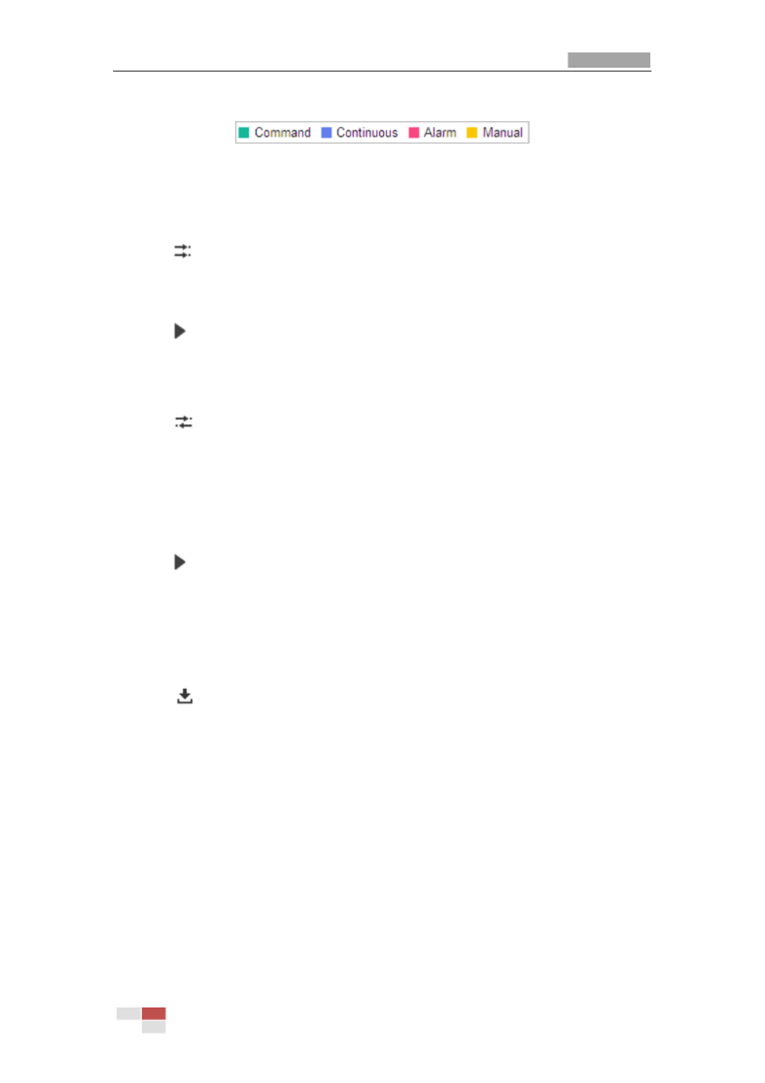
User Manual of Thermal Network Positioning system
© Hikvision
36
shown in Figure 4- . 18
Figure 4- Video Types 18
Synchronously play recorded videos of different channels
Steps
Steps
Steps
StepsSteps:
1. Click to enable synchronous playback function.
2. Choose camera channels.
3. Setting date and time of recorded videos.
4. Click to view the videos of optical channel and thermal channel synchronously.
Asynchronously play recorded videos of different channels
Steps
Steps
Steps
StepsSteps:
1. Click to enable asynchronous playback function.
2. Choose Channel No: 1.
3. Setting date and time of recorded videos.
4. Choose Channel No: 2.
5. Setting date and time of recorded videos.
6. Repeat step 2-5 to configure the date and time for different channels separately.
7. Click to view the videos of optical channel and thermal channel asynchronously.
4.5.2
4.5.2
4.5.2
4.5.24.5.2 Downloading Video Files
Downloading Video Files
Downloading Video Files
Downloading Video Files Downloading Video Files
Steps:
Steps:
Steps:
Steps: Steps:
1. Click on the playback interface. The pop-up menu is shown in Figure 4- . 19
2. Set the start time and end time. Click . The corresponding video files are listed
Search
Search
Search
SearchSearch
on the left.

User Manual of Thermal Network Positioning system
© Hikvision
37
Figure 4- Video Downloading interface 19
3. Check the checkbox in front of the video files that you need to download.
4. Click to download the video files.
4.6
4.6
4.6
4.64.6 Pictures
Pictures
Pictures
Pictures Pictures
Purpose:
Purpose:
Purpose:
Purpose: Purpose:
This section explains how to view the captured picture files stored in the network disks or
the memory cards and download the captured pictures.
Steps:
Steps:
Steps:
Steps: Steps:
1. Click on the menu bar to enter picture interface.
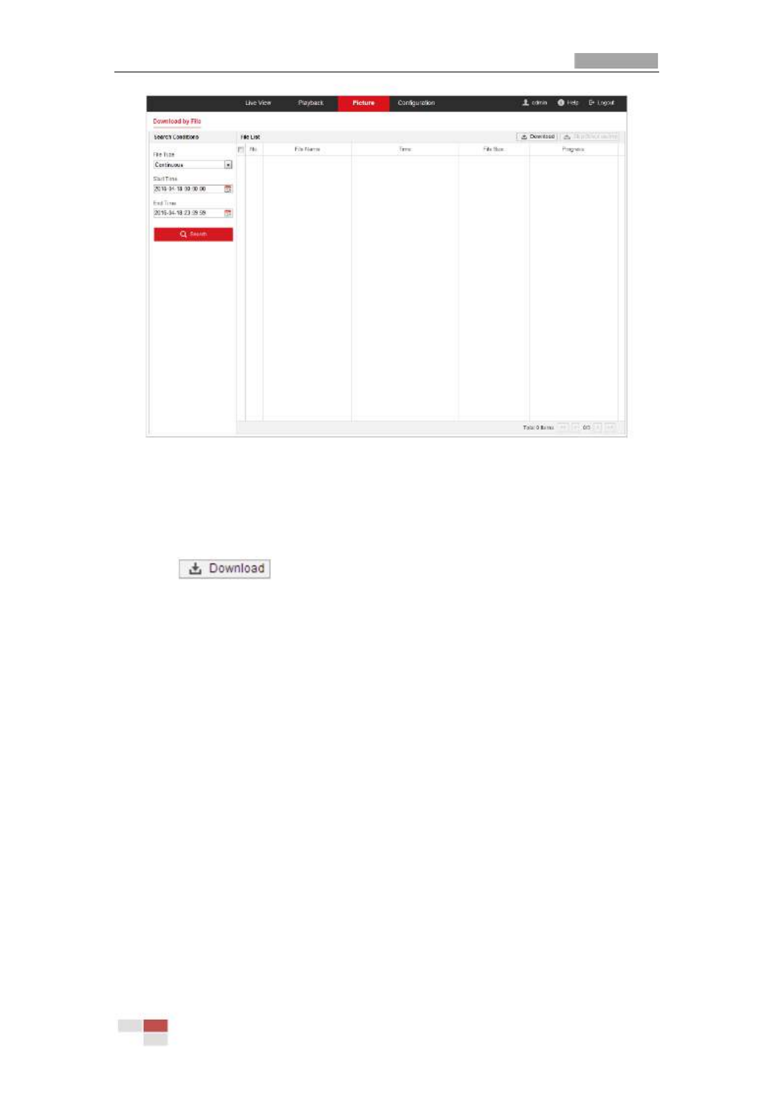
User Manual of Thermal Network Positioning system
© Hikvision
38
Figure 4-20 Picture Interface
2. Select the file type of capturing the pictures from the list as timing, alarm, motion, etc.
3. Set the start time and end time. Click . The corresponding picture files will be
Search
Search
Search
SearchSearch
listed.
4. Check the checkbox in front of the files that you need to download.
5. Click to download the files.

User Manual of Thermal Bi-spectrum Network Positioning System
© Hikvision
39
Chapter 5
Chapter 5
Chapter 5
Chapter 5Chapter 5
System Configuration
System Configuration
System Configuration
System ConfigurationSystem Configuration
5.1
5.1
5.1
5.15.1 Storage Settings
Storage Settings
Storage Settings
Storage Settings Storage Settings
Before you start:
Before you start:
Before you start:
Before you start:Before you start:
To configure record settings, please make sure that you have the network storage device
within the network or the memory card inserted in your positioning system.
5.1.1
5.1.1
5.1.1
5.1.15.1.1 Configuring Recording Schedu
Configuring Recording Schedu
Configuring Recording Schedu
Configuring Recording ScheduConfiguring Recording Schedule
le
le
le le
Purpose:
Purpose:
Purpose:
Purpose: Purpose:
There are two kinds of recording for the positioning systems: manual recording and
scheduled recording. In this section, you can follow the instructions to configure the
scheduled recording. By default, the record files of scheduled recording are stored in the
memory card (if supported) or in the network disk.
Steps:
Steps:
Steps:
Steps: Steps:
1. Enter the Record Schedule settings interface:
Configuration
Configuration
Configuration
Configuration Configuration > Storage > Sched
> Storage > Sched
> Storage > Sched
> Storage > Sched> Storage > Schedule Settings
ule Settings
ule Settings
ule Settings ule Settings > Record Sched
> Record Sched
> Record Sched
> Record Sched> Record Schedule
ule
ule
uleule
Figure 5-1 Recording Schedule Interface
2. Check the checkbox of Enable
Enable
Enable
Enable Enable to enable scheduled recording.
3. To set the advanced settings of the positioning system, click to enter the
advanced settings interface.

User Manual of Thermal Network Positioning system
© Hikvision
41
the recording schedule, you have to set the Alarm Type and check the checkbox of
Trigger Channel
Trigger Channel
Trigger Channel
Trigger ChannelTrigger Channel in the Linkage Method of Alarm Input settings interface. For
detailed information, please refer to Section Alarm Input
Alarm Input
Alarm Input
Alarm InputAlarm Input.
Record Triggered by Motion & Alarm: If you select Motion & Alarm, the video will
be recorded when the motion and alarm are triggered at the same time. Besides
configuring the recording schedule, you have to configure the settings on the
Motion Detection and Alarm Input settings interfaces.
Record Triggered by Motion | Alarm: If you select Motion | Alarm, the video will be
recorded when the external alarm is triggered or the motion is detected. Besides
configuring the recording schedule, you have to configure the settings on the
Motion Detection and Alarm Input settings interfaces.
Record Triggered by VCA events: If you select VCA, the video will be recorded
when the either of the VCA events is triggered. Besides configuring the recording
schedule, you have to configure the settings on the VCA interface.
VCA function varies depending on the models of positioning system.
Record Triggered by Event: If you select to record by event, the video will be
recorded when any of the events is triggered.
6. Click to save the settings.
5.1.2
5.1.2
5.1.2
5.1.25.1.2 Configuring Capture
Configuring Capture
Configuring Capture
Configuring CaptureConfiguring Capture Schedule
Schedule
Schedule
Schedule Schedule
Purpose:
Purpose:
Purpose:
Purpose: Purpose:
You can configure the scheduled snapshot and event-triggered snapshot. The captured
picture can be stored in the local storage or network storage.
Steps:
Steps:
Steps:
Steps: Steps:
1. Enter the Snapshot settings interface:
Configuration
Configuration
Configuration
Configuration Configuration > Storage
> Storage
> Storage
> Storage > Storage > Storage Settings
> Storage Settings
> Storage Settings
> Storage Settings > Storage Settings > Captur
> Captur
> Captur
> Captur> Capture
e
e
e e
Figure 5-3 Snapshot Settings

User Manual of Thermal Network Positioning system
© Hikvision
42
2. Click to enter the Capture Schedule interface.
3. Select the timeline of a certain day, click and drag the left button of the mouse to
set the capture schedule (the start time and end time of the recording task).
4. After you set the scheduled task, you can click and copy the task to other
days (optional).
5. After setting the capture schedule, you can click a capture segment to display
the segment capture settings interface to edit the segment capture parameters.
(optional)
Figure 5-4 Segment Snapshot Settings
6. Click to enter the advanced setting interface. You can select the
stream type of the capture.
7. Click to enter the Capture Parameters Interface.
8. Check the checkbox to enable continuous snapshot,
Enable
Enable
Enable
Enable Enable Timing
Timing
Timing
Timing Timing Snapshot
Snapshot
Snapshot
SnapshotSnapshot
and configure the schedule of timing snapshot. Check the Enable Event-triggered
Enable Event-triggered
Enable Event-triggered
Enable Event-triggeredEnable Event-triggered
Snapshot
Snapshot
Snapshot
SnapshotSnapshot checkbox to enable event-triggered snapshot.
9. Select the format, resolution, quality of the snapshot.
10. Set the time interval between two snapshots.
11. Click to save the settings.
Uploading to
Uploading to
Uploading to
Uploading to Uploading to FTP
FTP
FTP
FTP FTP
Please make sure that the FTP server is online.
You can follow below configuration instructions to upload the snapshots to FTP.
Upload continuous sna
Upload continuous sna
Upload continuous sna
Upload continuous snaUpload continuous snapshots to FTP
pshots to FTP
pshots to FTP
pshots to FTPpshots to FTP
Steps:
Steps:
Steps:
Steps: Steps:
1) Configure the FTP settings and check Upload
Upload
Upload
Upload Upload Pictu
Pictu
Pictu
PictuPicture
re
re
rere checkbox in FTP Settings
interface. Please refer to for more details to
Section 7.1.2
Section 7.1.2
Section 7.1.2
Section 7.1.2 Section 7.1.2 Configuring
Configuring
Configuring
Configuring Configuring FTP S
FTP S
FTP S
FTP SFTP Settings
ettings
ettings
ettingsettings
configure FTP parameters.
2) Check the Enable Timing
Enable Timing
Enable Timing
Enable Timing Enable Timing Snapshot
Snapshot
Snapshot
SnapshotSnapshot checkbox.
3) Click to set the snapshot schedule. Refer to
Edit
Edit
Edit
EditEdit Section
Section
Section
Section Section 5.2.1
5.2.1
5.2.1
5.2.1 5.2.1 Configur
Configur
Configur
ConfigurConfiguring
ing
ing
ing ing Motion
Motion
Motion
Motion Motion
Detection
Detection
Detection
DetectionDetection.
Upload event-triggered sn
Upload event-triggered sn
Upload event-triggered sn
Upload event-triggered snUpload event-triggered snapshots to FTP
apshots to FTP
apshots to FTP
apshots to FTPapshots to FTP

User Manual of Thermal Network Positioning system
© Hikvision
43
Steps:
Steps:
Steps:
Steps: Steps:
1) Configure the FTP settings and check checkbox in FTP Settings
Upload
Upload
Upload
Upload Upload Picture
Picture
Picture
PicturePicture
interface. Please refer to for more details to
Section 7.1.2
Section 7.1.2
Section 7.1.2
Section 7.1.2 Section 7.1.2 Configuring
Configuring
Configuring
Configuring Configuring FTP Se
FTP Se
FTP Se
FTP SeFTP Settings
ttings
ttings
ttingsttings
configure FTP parameters.
2) Check Uploa
Uploa
Uploa
UploaUpload to
d to
d to
d to d to FTP
FTP
FTP
FTPFTP checkbox in Motion Detection Settings or Alarm Input
interface. Refer to Sectio
Sectio
Sectio
SectioSection 5.2.1 Configuring Mo
n 5.2.1 Configuring Mo
n 5.2.1 Configuring Mo
n 5.2.1 Configuring Mon 5.2.1 Configuring Motion Detection
tion Detection
tion Detection
tion Detectiontion Detection.
3) Check the Enable Event-tri
Enable Event-tri
Enable Event-tri
Enable Event-triEnable Event-triggered Snaps
ggered Snaps
ggered Snaps
ggered Snapsggered Snapshot
hot
hot
hothot checkbox.
5.1.3
5.1.3
5.1.3
5.1.35.1.3 Configuring Net HDD
Configuring Net HDD
Configuring Net HDD
Configuring Net HDD Configuring Net HDD
Before you start:
Before you start:
Before you start:
Before you start:Before you start:
The network disk should be available within the network and properly configured to store
the recorded files, log files, etc.
Steps:
Steps:
Steps:
Steps: Steps:
Add the network di
Add the network di
Add the network di
Add the network diAdd the network disk
sk
sk
sk sk
1. Enter the NAS (Network-Attached Storage) settings interface:
Configuration
Configuration
Configuration
Configuration Configuration >
>
>
>> Storage > Storage
Storage > Storage
Storage > Storage
Storage > StorageStorage > Storage Management
Management
Management
Management Management > Ne
> Ne
> Ne
> Ne> Net HDD
t HDD
t HDD
t HDD t HDD
Figure 5-5 Select Net HDD Type
2. Enter the IP address and the file path of the network disk.
3. Select the mounting type. NFS and SMB/CIFS are selectable. You can set the user
name and password to guarantee the security if SMB/CIFS is selected.
Please refer to the NAS User Manual for creating the file path.
For your privacy and to better protect your system against security risks, we strongly
recommend the use of strong passwords for all functions and network devices. The
password should be something of your own choosing (using a minimum of 8
characters, including upper case letters, lower case letters, numbers and special
characters) in order to increase the security of your product.
Proper configuration of all passwords and other security settings is the responsibility of
the installer and/or end-user.

User Manual of Thermal Network Positioning system
© Hikvision
44
4. Click to add the network disk.
After having saved successfully, you need to reboot the positioning system to activate
the settings.
Initialize the a
Initialize the a
Initialize the a
Initialize the aInitialize the added networ
dded networ
dded networ
dded networdded network disk.
k disk.
k disk.
k disk. k disk.
1. Enter the HDD settings interface (Configurati
Configurati
Configurati
ConfiguratiConfiguration
on
on
on on >
>
>
> > Storage
Storage
Storage
Storage Storage >
>
>
> > Storage
Storage
Storage
Storage Storage Ma
Ma
Ma
MaManagement
nagement
nagement
nagement nagement >
>
>
> >
HDD
HDD
HDD
HDD HDD Ma
Ma
Ma
MaManagement
nagement
nagement
nagementnagement), in which you can view the capacity, free space, status, type and
property of the disk.
Figure 5-6 Storage Management Interface
2. If the status of the disk is , check the corresponding checkbox to select the
Uninitialized
Uninitialized
Uninitialized
UninitializedUninitialized
disk and click to start initializing the disk.
Format
Format
Format
FormatFormat
3. When the initialization completed, the status of disk will become as shown in
Normal
Normal
Normal
Normal Normal
Figure 5-7.
.
.
..
Figure 5-7 View Disk Status
Define the Quot
Define the Quot
Define the Quot
Define the QuotDefine the Quota for Recor
a for Recor
a for Recor
a for Recora for Record and Pictures
d and Pictures
d and Pictures
d and Pictures d and Pictures
1. Input the quota percentage for picture and for record.
2. Click Save
Save
Save
Save Save and refresh the browser page to activate the settings.
Figure 5-8 Quota Settings

User Manual of Thermal Network Positioning system
© Hikvision
45
Up to 8 NAS disks can be connected to the positioning system.
To initialize and use the memory card after insert it to the positioning system, please
refer to the steps of NAS disk initialization
5.2
5.2
5.2
5.25.2 Event Configuration
Event Configuration
Event Configuration
Event ConfigurationEvent Configuration
Purpose:
Purpose:
Purpose:
Purpose: Purpose:
This section explains how to configure the network positioning system to respond to
alarm events, including motion detection, video tampering alarm input, alarm output and
exception. These events can trigger the alarm actions, such as Send Email, Notify
Surveillance Center, etc.
For example, when motion detection is triggered, the network positioning system sends a
notification to an e-mail address.
On the event configuration page, click to show the PTZ control panel or click to
hide it.
Click the direction buttons to control the pan/tilt movements.
Click the zoom/iris/focus buttons to realize lens control.
The functions vary depending on the models positioning system. of
5.2.1
5.2.1
5.2.1
5.2.15.2.1 Con
Con
Con
ConConfiguring Motion Detection
figuring Motion Detection
figuring Motion Detection
figuring Motion Detection figuring Motion Detection
Purpose:
Purpose:
Purpose:
Purpose: Purpose:
Motion detection is a feature which can trigger alarm actions and actions of recording
videos when the motion occurred in the surveillance scene.
Steps:
Steps:
Steps:
Steps: Steps:
1. Enter the motion detection setting interface:
Configuration
Configuration
Configuration
Configuration Configuration > Event > Basic Eve
> Event > Basic Eve
> Event > Basic Eve
> Event > Basic Eve> Event > Basic Event > Motion
nt > Motion
nt > Motion
nt > Motion nt > Motion Detection
Detection
Detection
Detection Detection
2. Select the channel to set the motion detection.
3. Check the checkbox of the Enable Motion De
Enable Motion De
Enable Motion De
Enable Motion De Enable Motion Detection
tection
tection
tectiontection to enable this function.
You can check the checkbox if you want the
Enable
Enable
Enable
Enable Enable Dynamic
Dynamic
Dynamic
Dynamic Dynamic Analysis
Analysis
Analysis
Analysis Analysis for
for
for
for for Motion
Motion
Motion
MotionMotion
detected object get marked with rectangle in the live view.
4. Select the configuration mode as or and set the corresponding motion
Normal
Normal
Normal
NormalNormal Expert
Expert
Expert
ExpertExpert
detection parameters.
Normal
Normal
Normal
Normal Normal

User Manual of Thermal Network Positioning system
© Hikvision
46
Figure 5-9 Motion Detection Settings-Normal
Steps:
Steps:
Steps:
Steps: Steps:
(1) Click and drag the mouse on the live video image to draw a motion
detection area.
(2) Click to finish drawing.
You can draw up to 8 motion detection areas on the same image.
You can click to clear all of the areas.
(3) Move the slider to set the
sensitivity of the detection.
Expe
Expe
Expe
ExpeExpert
rt
rt
rt rt

User Manual of Thermal Network Positioning system
© Hikvision
47
Figure 5-10 Motion Detection Settings-Expert
Steps:
(1) Set the Schedu
Schedu
Schedu
ScheduSchedule Image Se
le Image Se
le Image Se
le Image Sele Image Settings
ttings
ttings
ttingsttings, there are OFF
OFF
OFF
OFFOFF Auto-Swit
Auto-Swit
Auto-Swit
Auto-SwitAuto-Switch
ch
ch
ch ch , and
Scheduled-Switc
Scheduled-Switc
Scheduled-Switc
Scheduled-SwitcScheduled-Switch
h
h
hh selectable. If the schedule image switch mode is enabled, you
can configure the detection rule for the day and night separately.
OFF:
OFF:
OFF:
OFF: OFF: Disable the day and night switch.
Auto-Switch:
Auto-Switch:
Auto-Switch:
Auto-Switch: Auto-Switch: Switch the day and night mode according to the illumination
automatically.
Scheduled-Switc
Scheduled-Switc
Scheduled-Switc
Scheduled-SwitcScheduled-Switch:
h:
h:
h: h: Switch to the day mode at 6:00 a.m., and switch to the night
mode at 18:00 p.m..
(2) Select to configure in the dropdown list. Area No.
Area No.
Area No.
Area No.Area No.
(3) Set the values of sensitivity and proportion of object on area.
Sensitivity:
Sensitivity:
Sensitivity:
Sensitivity: Sensitivity: The greater the value is, the easier the alarm will be triggered.
Proportion of
Proportion of
Proportion of
Proportion of Proportion of Object on Ar
Object on Ar
Object on Ar
Object on ArObject on Area:
ea:
ea:
ea: ea: When the size proportion of the moving object
exceeds the predefined value, the alarm will be triggered. The less the value is,
the easier the alarm will be triggered.
5. Set the Arming S
Arming S
Arming S
Arming SArming Schedule
chedule
chedule
chedulechedule for Motion Detection.
(1) Click tab to enter the arming schedule setting interface.
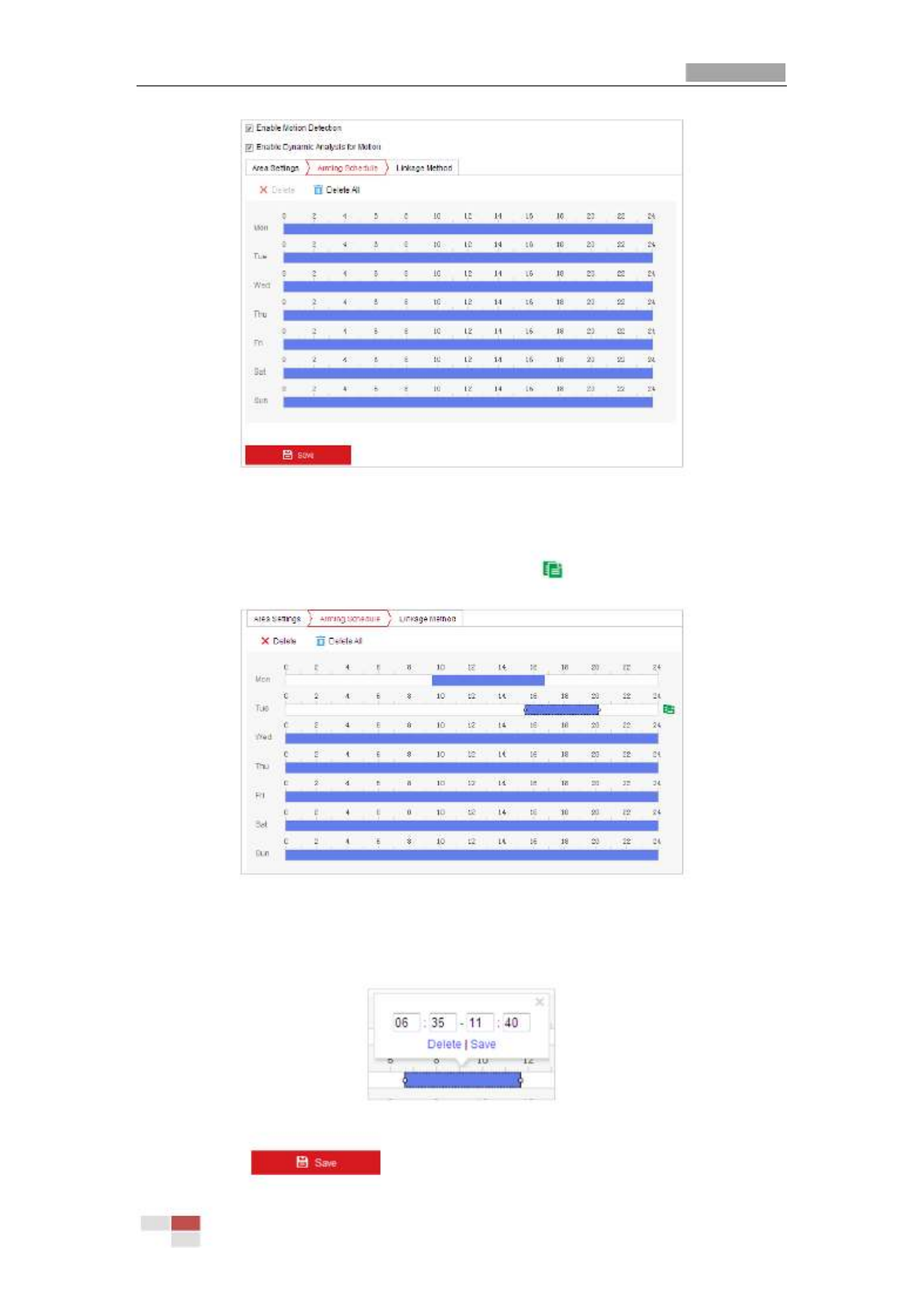
User Manual of Thermal Network Positioning system
© Hikvision
48
Figure 5- Arming Schedule 11
(2) Select the timeline of a certain day, click and drag the mouse to set the arming
schedule (the start time and end time of the arming task).
(3) After you set the scheduled task, you can click and copy the task to other
days (optional).
Figure 5- Arming Time Schedule 12
(4) After setting the arming schedule, you can click a segment to display the
segment arming settings interface to edit the segment record parameters
(optional).
Figure 5- Segment Arming Settings 13
(5) Click to save the settings.

User Manual of Thermal Network Positioning system
© Hikvision
49
The time of each period cannot be overlapped. Up to 8 periods can be configured for
each day.
6. Set the Ala
Ala
Ala
AlaAlarm Actions
rm Actions
rm Actions
rm Actionsrm Actions for Motion Detection.
Click tab to enter the interface.
Linkage Method
Linkage Method
Linkage Method
Linkage MethodLinkage Method
You can specify the linkage method when an event occurs. The following contents
are about how to configure the different types of linkage method.
Figure 5- Linkage Method 14
Check the checkbox to select the linkage method. Notify Surveillance Center,
Send Email, Upload to FTP/Memory/NAS, Trigger Alarm Output and Trigger
Recording are selectable.
Notify Surveillan
Notify Surveillan
Notify Surveillan
Notify SurveillanNotify Surveillance Center
ce Center
ce Center
ce Center ce Center
Send an exception or alarm signal to remote management software when an
event occurs.
Send Email
Send Email
Send Email
Send Email Send Email
Send an email with alarm information to a user or users when an event occurs.
To send the Email when an event occurs, you need to refer to Section
Section
Section
SectionSection Configuring
Configuring
Configuring
Configuring Configuring
Email Settings
Email Settings
Email Settings
Email Settings Email Settings to set the Email parameters.
Upload to FTP/Me
Upload to FTP/Me
Upload to FTP/Me
Upload to FTP/MeUpload to FTP/Memory/NAS
mory/NAS
mory/NAS
mory/NASmory/NAS
Capture the image when an alarm is triggered and upload the picture to a FTP
server.

User Manual of Thermal Network Positioning system
© Hikvision
50
You need a FTP server and set FTP parameters first. Refer to S
S
S
SSection
ection
ection
ection ection Configuring
Configuring
Configuring
ConfiguringConfiguring
FTP Settings
FTP Settings
FTP Settings
FTP SettingsFTP Settings
for setting FTP parameters.
Trigger Alarm Out
Trigger Alarm Out
Trigger Alarm Out
Trigger Alarm OutTrigger Alarm Output
put
put
put put
Trigger one or more external alarm outputs when an event occurs.
To trigger an alarm output when an event occurs, please refer to Se
Se
Se
SeSection
ction
ction
ction ction 5.2.4
5.2.4
5.2.4
5.2.4 5.2.4
Configuring Alarm Ou
Configuring Alarm Ou
Configuring Alarm Ou
Configuring Alarm OuConfiguring Alarm Output
tput
tput
tputtput to set the alarm output parameters.
Trigger Recordin
Trigger Recordin
Trigger Recordin
Trigger RecordinTrigger Recording
g
g
g g
Record a video when an event occurs.
You have to set the recording schedule to realize this function. Please refer to
Section 5.1.1 Configuring
Section 5.1.1 Configuring
Section 5.1.1 Configuring
Section 5.1.1 Configuring Section 5.1.1 Configuring Recording Sche
Recording Sche
Recording Sche
Recording ScheRecording Schedule
dule
dule
duledule
for settings the recording schedule.
5.2.2
5.2.2
5.2.2
5.2.25.2.2 Configuring Video Tampering
Configuring Video Tampering
Configuring Video Tampering
Configuring Video TamperingConfiguring Video Tampering Alarm
Alarm
Alarm
Alarm Alarm
Purpose:
Purpose:
Purpose:
Purpose: Purpose:
You can configure the positioning system to trigger the alarm actions when the lens is
covered.
Steps:
Steps:
Steps:
Steps: Steps:
1. Enter the Video Tampering settings interface :
Configuration
Configuration
Configuration
Configuration Configuration > Event > Basic Eve
> Event > Basic Eve
> Event > Basic Eve
> Event > Basic Eve> Event > Basic Event > Video Tamperi
nt > Video Tamperi
nt > Video Tamperi
nt > Video Tamperint > Video Tampering
ng
ng
ng ng
2. Select the channel to set the video tampering alarm.

User Manual of Thermal Network Positioning system
© Hikvision
51
Figure 5- Tampering Alarm 15
3. Check Enable
Enable
Enable
Enable Enable checkbox to enable the tampering detection.
4. Click tab to enter the arming schedule setting interface. The
arming schedule configuration is the same as the setting of the arming schedule for
motion detection. Refer to Section
Section
Section
SectionSection 5.2.1 Configuring M
5.2.1 Configuring M
5.2.1 Configuring M
5.2.1 Configuring M5.2.1 Configuring Motion De
otion De
otion De
otion Deotion Detection
tection
tection
tectiontection.
5. Click tab to select the linkage method taken for tampering, notify
surveillance center, send email and trigger alarm output are selectable. Refer to
Section
Section
Section
SectionSection
5.2.1 Configuring Mo
5.2.1 Configuring Mo
5.2.1 Configuring Mo
5.2.1 Configuring Mo5.2.1 Configuring Motion Detec
tion Detec
tion Detec
tion Detection Detection
tion
tion
tiontion.
6. Click to save the settings.
5.2.3
5.2.3
5.2.3
5.2.35.2.3 Configuring Alarm Input
Configuring Alarm Input
Configuring Alarm Input
Configuring Alarm InputConfiguring Alarm Input
Steps:
Steps:
Steps:
Steps: Steps:
1. Enter the Alarm Input settings interface:
Configuration
Configuration
Configuration
Configuration Configuration > Event > Ba
> Event > Ba
> Event > Ba
> Event > Ba> Event > Basic Event > Alarm
sic Event > Alarm
sic Event > Alarm
sic Event > Alarmsic Event > Alarm I
I
I
IInput
nput
nput
nputnput
2. Choose the alarm input No. and the Alarm Type. The alarm type can be NO (Normally
Open) and NC (Normally Closed).
3. Edit the name in to set a name for the
alarm input (optional).

User Manual of Thermal Network Positioning system
© Hikvision
52
Figure 5- Alarm Input Settings 16
4. Click tab to enter the arming schedule setting interface. The
arming schedule configuration is the same as the setting of the arming schedule for
motion detection. Refer to Section
Section
Section
SectionSection 5.2.1 Configuring
5.2.1 Configuring
5.2.1 Configuring
5.2.1 Configuring 5.2.1 Configuring Motion De
Motion De
Motion De
Motion DeMotion Detection
tection
tection
tectiontection.
5. Click tab to select the linkage method taken for alarm input,
including Notify Surveillance Center, Send Email, Upload to FTP/Memory Card/NAS,
Trigger Alarm Output and Trigger Recording. Refer to Section
Section
Section
SectionSection 5.2.1
5.2.1
5.2.1
5.2.1 5.2.1 Configuring Motion
Configuring Motion
Configuring Motion
Configuring Motion Configuring Motion
Detection
Detection
Detection
DetectionDetection.
6. You can also choose the PTZ linking for the alarm input. Check the relative checkbox
and select the No. to enable Preset Calling, Patrol Calling or Pattern Calling.
7. You can copy your settings to other alarm inputs.
8. Click to save the settings.
Figure 5- Linkage Method 17

User Manual of Thermal Network Positioning system
© Hikvision
53
5.2.4
5.2.4
5.2.4
5.2.45.2.4 Configuring Alarm Output
Configuring Alarm Output
Configuring Alarm Output
Configuring Alarm OutputConfiguring Alarm Output
Steps:
Steps:
Steps:
Steps: Steps:
1. Enter the Alarm Output settings interface:
Configuration>
Configuration>
Configuration>
Configuration> Configuration> Event > Basic Eve
Event > Basic Eve
Event > Basic Eve
Event > Basic EveEvent > Basic Event > Alarm Out
nt > Alarm Out
nt > Alarm Out
nt > Alarm Outnt > Alarm Output
put
put
putput
2. Select one alarm output channel in the Alarm Outpu
Alarm Outpu
Alarm Outpu
Alarm Outpu Alarm Output
t
t
tt dropdown list.
3. Set a name in for the alarm output
(optional).
4. The Dela
Dela
Dela
DelaDelay
y
y
yy time can be set to 5sec
5sec
5sec
5sec5sec, 10se
10se
10se
10se10sec
c
c
cc 30sec
30sec
30sec
30sec30sec, , 1min
1min
1min
1min1min 2min
2min
2min
2min2min 5mi
5mi
5mi
5mi5min, 10min
n, 10min
n, 10min
n, 10minn, 10min, , or Manual
Manual
Manual
Manual Manual.
The delay time refers to the time duration that the alarm output remains in effect after
alarm occurs.
5. Clic tab to enter the arming schedule setting interface. The time k
schedule configuration is the same as the settings of the arming schedule for motion
detection. Refer to
Section
Section
Section
Section Section 5.2.1
5.2.1
5.2.1
5.2.1 5.2.1 Configuring Mo
Configuring Mo
Configuring Mo
Configuring MoConfiguring Motion Detection
tion Detection
tion Detection
tion Detectiontion Detection.
Figure 5- Alarm Output Settings 18
6. You can copy the settings to other alarm outputs.
7. Click to save the settings.

User Manual of Thermal Network Positioning system
© Hikvision
54
5.2.5
5.2.5
5.2.5
5.2.55.2.5 Handling Exception
Handling Exception
Handling Exception
Handling Exception Handling Exception
The exception type can be HDD full, HDD error, network disconnected, IP address
conflicted and illegal login to the positioning system s.
Steps:
Steps:
Steps:
Steps: Steps:
1. Enter the Exception settings interface:
Configuration
Configuration
Configuration
Configuration Configuration > Event > Ba
> Event > Ba
> Event > Ba
> Event > Ba> Event > Basic Event > Ex
sic Event > Ex
sic Event > Ex
sic Event > Exsic Event > Exception
ception
ception
ceptionception
2. Check the checkbox to set the actions taken for the Exception alarm. Refer to Section
Section
Section
SectionSection
5.2.1 Configuring Mo
5.2.1 Configuring Mo
5.2.1 Configuring Mo
5.2.1 Configuring Mo5.2.1 Configuring Motion Detection
tion Detection
tion Detection
tion Detectiontion Detection.
Figure 5- Exception Settings 19
3. Click to save the settings.
5.2.1
5.2.1
5.2.1
5.2.15.2.1 Detecting
Detecting
Detecting
DetectingDetecting Audio Exception
Audio Exception
Audio Exception
Audio Exception Audio Exception
Purpose:
Purpose:
Purpose:
Purpose: Purpose:
When you enable this function and audio exception occurs, the alarm actions will be
triggered.
Steps:
Steps:
Steps:
Steps: Steps:
1. Enter the video audio exception detection interface:

User Manual of Thermal Network Positioning system
© Hikvision
55
Configuration
Configuration
Configuration
Configuration Configuration > Event > S
> Event > S
> Event > S
> Event > S> Event > Smart Event > Au
mart Event > Au
mart Event > Au
mart Event > Aumart Event > Audio Except
dio Except
dio Except
dio Exceptdio Exception Detectio
ion Detectio
ion Detectio
ion Detectioion Detection
n
n
nn
Figure 5-20 Audio Exception Detection
2. Check the checkbox of
Audio Loss
Audio Loss
Audio Loss
Audio Loss Audio Loss Detection
Detection
Detection
DetectionDetection
to enable the audio input exception
detection.
3. Check the checkbox of
Sudden
Sudden
Sudden
Sudden Sudden Increase
Increase
Increase
Increase Increase of
of
of
of of Sound
Sound
Sound
SoundSound
Intensity
Intensity
Intensity
Intensity Intensity Detection
Detection
Detection
Detection Detection checkbox to
enable the sudden rise detection.
Sensitivity
Sensitivity
Sensitivity
SensitivitySensitivity: Range [1-100], the smaller the value the more severe the sound change
will trigger the detection.
Sound
Sound
Sound
SoundSound Intensity
Intensity
Intensity
IntensityIntensity Threshold
Threshold
Threshold
ThresholdThreshold : Range [1-100], it can filter the sound in the environment,
the louder the environment sound, the higher the value should be. You can adjust it
according to the actual environment.
4. Check the checkbox of checkbox to
Sudden
Sudden
Sudden
Sudden Sudden Decrease
Decrease
Decrease
Decrease Decrease of
of
of
of of Sound
Sound
Sound
Sound Sound Intensity
Intensity
Intensity
Intensity Intensity Detection
Detection
Detection
Detection Detection
enable the sudden drop detection.
Sensitivity
Sensitivity
Sensitivity
SensitivitySensitivity: Range [1-100], the smaller the value the more severe the sound change will
trigger the detection.
5. Click tab to enter the arming schedule setting interface. The time
schedule configuration is the same as the settings of the arming schedule for motion
detection. Refer to Secti
Secti
Secti
SectiSection
on
on
onon 5.2.1 Configuring Mo
5.2.1 Configuring Mo
5.2.1 Configuring Mo
5.2.1 Configuring Mo5.2.1 Configuring Motion Detec
tion Detec
tion Detec
tion Detection Detection
tion
tion
tiontion .
6. Click tab to select the linkage method taken for the audio input
exception, Notify Surveillance Center, Send Email, Trigger Alarm Output and Trigger
Recording are selectable. Refer to Section
Section
Section
SectionSection 5.2.1 Conf
5.2.1 Conf
5.2.1 Conf
5.2.1 Conf5.2.1 Configuring Motion De
iguring Motion De
iguring Motion De
iguring Motion Deiguring Motion Detection
tection
tection
tectiontection .

User Manual of Thermal Network Positioning system
© Hikvision
56
7. Click to save the settings.
5.3
5.3
5.3
5.35.3 Fire Source Detecti
Fire Source Detecti
Fire Source Detecti
Fire Source DetectiFire Source Detection Configuration
on Configuration
on Configuration
on Configuration on Configuration
The functions vary depending on the models of positioning system.
If GPS informaon is required for
plaorm accessing?
Start
YES NO
Enable GPS of Posion
Sengs
Set the applicaon scene
and zoom parameters.
Set the VCA resource to
Fire Detecon
Enable Fire Detecon
(Event Dynamic Fire Source Detection)>
If the PTZ funcon is supported by the
camera?
YES
END
NO
Enable Fire Detecon Shield.
Enable the
patrol/park/linear scan.
Set the north as the
Inial Posion
Enable the re point in
the Local Sengs.

User Manual of Thermal Network Positioning system
© Hikvision
57
5.3.1
5.3.1
5.3.1
5.3.15.3.1 Configuring Initial Position
Configuring Initial Position
Configuring Initial Position
Configuring Initial Position Configuring Initial Position
Purpose:
Purpose:
Purpose:
Purpose: Purpose:
The initial position is the origin of PTZ coordinates. It can be the factory default initial
position. You can also customize the initial position according to your own demand.
If you connect the device to the system platform, the platform can mark all the fire
positions.
Steps:
Steps:
Steps:
Steps: Steps:
1. Enter the Position Settings interface:
Configuration
Configuration
Configuration
ConfigurationConfiguration > PTZ
PTZ
PTZ
PTZPTZ > Position Settings
Position Settings
Position Settings
Position SettingsPosition Settings.
Figure 5- Position Settings 21
2. Set the compass parameters.
(1) Select PT Mode as Manua
Manua
Manua
ManuaManual
l
l
ll.
(2) Click the PTZ control buttons to find the north direction; you can also call a
defined preset and set it as the north direction.
(3) Click Set as N
Set as N
Set as N
Set as NSet as North
orth
orth
orthorth to save the position.
(4) Optionally, you can click Point to North
Point to North
Point to North
Point to NorthPoint to North to move the device to the north direction
if the north direction was once saved.
3. Set the sensitivity of Vandal-proof Alarm. The higher the value is, more easily the

User Manual of Thermal Network Positioning system
© Hikvision
58
alarm will be triggered.
4. Enable or disable the alarm uploading and alarm voice warning function.
5. Set GPS settings.
(1) Select Longitude-Latitude Mode as Manual
Manual
Manual
ManualManual.
(2) Select longitude and latitude as East or West according to the actual position.
(3) Enter the value of longitude and latitude in three textboxes.
6. Click Point to
Point to
Point to
Point to Point to North
North
North
North North
and save
.
.
.
..
7. Enter the Initial Position Configuration interface:
Configuration
Configuration
Configuration
Configuration Configuration > PTZ
PTZ
PTZ
PTZ PTZ Initi
Initi
Initi
Initi Initial Position
al Position
al Position
al Positional Position>
Figure 5- PTZ Configuration 22
1. Click the PTZ control buttons to find a position as the initial position of the positioning
system; you can also call a defined preset and set it as the initial position of the
positioning system.
2. Click to save the position.
Set
Set
Set
SetSet
Call/delete
Call/delete
Call/delete
Call/delete Call/delete an Initial Position:
an Initial Position:
an Initial Position:
an Initial Position:an Initial Position:
You can click to call the initial position. You can click to delete the initial position
and restore the factory default initial position.
5.3.2
5.3.2
5.3.2
5.3.25.3.2 Configuring Dynamic
Configuring Dynamic
Configuring Dynamic
Configuring DynamicConfiguring Dynamic Fire Source Detection
Fire Source Detection
Fire Source Detection
Fire Source Detection Fire Source Detection
Purpose:
Purpose:
Purpose:
Purpose: Purpose:
When you enable this function and fire source or smoke is detected, the alarm actions will
be triggered. You can set different detection mode, fire source zoom mode, and so on.
Steps:
Steps:
Steps:
Steps: Steps:

User Manual of Thermal Network Positioning system
© Hikvision
59
1. Enter to select
Configuration>
Configuration>
Configuration>
Configuration>Configuration>System>Maintenance>VCA Resource Type
System>Maintenance>VCA Resource Type
System>Maintenance>VCA Resource Type
System>Maintenance>VCA Resource TypeSystem>Maintenance>VCA Resource Type Tempera
Tempera
Tempera
TemperaTempera
ture Measurement + Fire Detection
ture Measurement + Fire Detection
ture Measurement + Fire Detection
ture Measurement + Fire Detection ture Measurement + Fire Detection as VCA Resource Type.
2. Enter the fire source detection interface:
Configuration
Configuration
Configuration
Configuration Configuration > Event > Sma
> Event > Sma
> Event > Sma
> Event > Sma> Event > Smart Event > Dyna
rt Event > Dyna
rt Event > Dyna
rt Event > Dynart Event > Dynamic Fire Source Dete
mic Fire Source Dete
mic Fire Source Dete
mic Fire Source Detemic Fire Source Detection
ction
ction
ctionction
Figure 5- Fire Source Detection 23
3. Check Enable
Enable
Enable
EnableEnable Dynamic Fire
Dynamic Fire
Dynamic Fire
Dynamic Fire Dynamic Fire Source Detection
Source Detection
Source Detection
Source DetectionSource Detection.
4. Select the from the list. Forest-Fire Prevention, Straw Burning,
Application Scene
Application Scene
Application Scene
Application SceneApplication Scene
High-building, and Indoor/Perimeter are selectable. Set the for
Installation Height
Installation Height
Installation Height
Installation HeightInstallation Height
scene if required.
5. Set the fire detection parameters:
Detection Mode
Detection Mode
Detection Mode
Detection ModeDetection Mode:
:
:
:: Select detection mode as , and the system
by Multiple Frame
by Multiple Frame
by Multiple Frame
by Multiple Frameby Multiple Frame
alarms with high accuracy. Select detection mode as , and the
b
b
b
bby
y
y
y y Single
Single
Single
Single Single Frame
Frame
Frame
FrameFrame
system alarms with short delay.
Sensitivity:
Sensitivity:
Sensitivity:
Sensitivity:Sensitivity: Range [1-100], the smaller the value is, the fire source of lower
temperature can be detected.
Hold-and-Alarm
Hold-and-Alarm
Hold-and-Alarm
Hold-and-Alarm Hold-and-Alarm Mode:
Mode:
Mode:
Mode: Mode: The system will stop when it detects the fire source. You
can set the duration while it keeps still.
- In mode, you can set the dwell time, range [0-120]. During the dwell
Auto
Auto
Auto
AutoAuto
time the camera stays still where it detects the fire source when
performing auto scan, patrol, pattern, scheduled task, and park action.
- In Mode, the device stays still where it detects the fire source, until
Manual
Manual
Manual
ManualManual
you manually moves the camera.
Fire
Fire
Fire
Fire Fire Source
Source
Source
Source Source Zoom
Zoom
Zoom
Zoom Zoom Ratio:
Ratio:
Ratio:
Ratio:Ratio: Set the zoom ratio of the optical channel when it detects
the fire source. In Auto mode, the optical channel changes its zoom ratio until two
channels have the same field of view. In Manual mode, you can set the optical

User Manual of Thermal Network Positioning system
© Hikvision
60
zoom ratio.
Cancel
Cancel
Cancel
Cancel Cancel Repeated
Repeated
Repeated
Repeated Repeated Alarm:
Alarm:
Alarm:
Alarm:Alarm: Enable this function to trigger alarm only once for same
place during one day.
6. Check the checkbox of to display a red frame
Display
Display
Display
Display Display Fire
Fire
Fire
Fire Fire Source
Source
Source
Source Source Frame
Frame
Frame
Frame Frame on
on
on
on on Stre
Stre
Stre
StreStream
am
am
amam
around the fire source on stream when fire occurs. (Optional)
7. Check the checkbox to select the linkage method taken for the alarm input. Refer to
Step 3 in Section 5.2.1 Configuring Motion Detection. In the field of ,
Other
Other
Other
Other Other Linkage
Linkage
Linkage
LinkageLinkage you
can check the checkbox to enable the alarm output (The alarm output number varies
depending on device ability).
8. Click to save the settings.
5.3.3
5.3.3
5.3.3
5.3.35.3.3 Configuring Fire Sou
Configuring Fire Sou
Configuring Fire Sou
Configuring Fire SouConfiguring Fire Source Detection Shield
rce Detection Shield
rce Detection Shield
rce Detection Shield rce Detection Shield
Purpose:
Purpose:
Purpose:
Purpose: Purpose:
Fire Source Detection Shield enables you to shield certain areas from being detected in
fire source detection.
The Fire Source Detection Shield function is supported by the optical lens only.
Steps:
Steps:
Steps:
Steps: Steps:
1. Enter the Fire Source Detection Shield Setting interface:
Configuration
Configuration
Configuration
Configuration Configuration > Event
Event
Event
Event Event > Smart Event
Smart Event
Smart Event
Smart Event Smart Event > Fire Sour
Fire Sour
Fire Sour
Fire Sour Fire Source Detection S
ce Detection S
ce Detection S
ce Detection Sce Detection Shield
hield
hield
hieldhield

User Manual of Thermal Network Positioning system
© Hikvision
61
Figure 5- Fire Source Detection Shield 24
2. Click the PTZ control buttons to find the area you want to shield from the smoke
detection.
3. Click and drag the mouse in the live video window to draw the area.
Draw Area
Draw Area
Draw Area
Draw AreaDraw Area
4. You can drag the corners of the red rectangle area to change its shape and size.
5. Click to finish drawing or click to clear all of the areas you set
Stop
Stop
Stop
Stop Stop Drawing
Drawing
Drawing
DrawingDrawing Clear
Clear
Clear
Clear Clear All
All
All
AllAll
without saving them.
6. Set the value of on your demand, and then the shield will only
Active
Active
Active
Active Active Zoom
Zoom
Zoom
Zoom Zoom Ratio
Ratio
Ratio
RatioRatio
appear when the zoom ratio is greater than the predefined value.
7. Click to save the smoke detection shield, and it will be listed in the
Add
Add
Add
AddAdd Fire
Fire
Fire
Fire Fire Source
Source
Source
Source Source
Detection Shield List
Detection Shield List
Detection Shield List
Detection Shield ListDetection Shield List area; you can select a region and click to delete it from the
Delete
Delete
Delete
DeleteDelete
list; you can also define the color of the regions.
8. Check the checkbox of Enable Fire
Enable Fire
Enable Fire
Enable Fire Enable Fire Source Detectio
Source Detectio
Source Detectio
Source DetectioSource Detection
n
n
n n Shield
Shield
Shield
ShieldShield to enable this function.
You are allowed to draw up to 24 areas on the same image.
9. Click to save the settings.
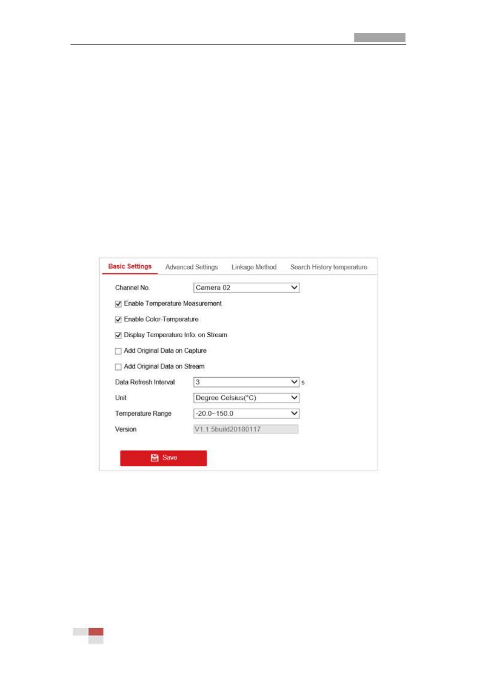
User Manual of Thermal Network Positioning system
© Hikvision
62
5.4
5.4
5.4
5.45.4 Temperature Measureme
Temperature Measureme
Temperature Measureme
Temperature MeasuremeTemperature Measurement
nt
nt
nt nt
Purpose:
Purpose:
Purpose:
Purpose: Purpose:
When you enable this function, it measures the actual temperature of the spot being
monitored. The device alarms when temperature exceeds the temperature threshold
value.
Before You Start:
Before You Start:
Before You Start:
Before You Start: Before You Start:
Enter to select
Configuration
Configuration
Configuration
Configuration Configuration >
>
>
> > Advanced
Advanced
Advanced
Advanced Advanced Configuration
Configuration
Configuration
Configuration Configuration >
>
>
> > System
System
System
System System >
>
>
> > VCA
VCA
VCA
VCA VCA Resource
Resource
Resource
Resource Resource Type
Type
Type
TypeType
Temperature Me
Temperature Me
Temperature Me
Temperature MeTemperature Measurement + Beha
asurement + Beha
asurement + Beha
asurement + Behaasurement + Behavior Analysis
vior Analysis
vior Analysis
vior Analysisvior Analysis as VCA Resource Type.
5.4.1
5.4.1
5.4.1
5.4.15.4.1 Temperature Measurement Configuration
Temperature Measurement Configuration
Temperature Measurement Configuration
Temperature Measurement ConfigurationTemperature Measurement Configuration
Steps:
Steps:
Steps:
Steps: Steps:
1. Enter Configurat
Configurat
Configurat
ConfiguratConfiguration > Tem
ion > Tem
ion > Tem
ion > Temion > Temperature Measureme
perature Measureme
perature Measureme
perature Measuremeperature Measurement > Basic Settings
nt > Basic Settings
nt > Basic Settings
nt > Basic Settings nt > Basic Settings Configuration.
Figure 5- Temperature Measurement Configuration 25
2. Check the checkboxes of the interface to set the temperature measurement
configurations.
Enable Temperatu
Enable Temperatu
Enable Temperatu
Enable TemperatuEnable Temperature Measureme
re Measureme
re Measureme
re Measuremere Measurement
nt
nt
ntnt: Check the checkbox to enable
temperature measurement function.
Enable Color-Te
Enable Color-Te
Enable Color-Te
Enable Color-TeEnable Color-Temperature
mperature
mperature
mperaturemperature: Check the checkbox to display temperature pallet
in live view.
Display Tempe
Display Tempe
Display Tempe
Display TempeDisplay Temperature Info. on Strea
rature Info. on Strea
rature Info. on Strea
rature Info. on Strearature Info. on Stream
m
m
mm: Check the checkbox to display
temperature information in live view.

User Manual of Thermal Network Positioning system
© Hikvision
64
Alarm
Alarm
Alarm
AlarmAlarm: When the temperature of target exceeds the , and this
Alarm
Alarm
Alarm
Alarm Alarm Threshold
Threshold
Threshold
ThresholdThreshold
status keeps NOT shorter than the , it triggers the Alarm.
Filtering Time
Filtering Time
Filtering Time
Filtering TimeFiltering Time
Check the checkbox of to set link the pre-alarm with the connected
Alarm
Alarm
Alarm
Alarm Alarm Output
Output
Output
OutputOutput
alarm device.
4. Click .
Save
Save
Save
Save Save
Figure 5- Temperature Measurement Configuration 26
(For Expert Mode)
1. Enter Configurat
Configurat
Configurat
ConfiguratConfiguration > Tem
ion > Tem
ion > Tem
ion > Temion > Temperature M
perature M
perature M
perature Mperature Measurement >
easurement >
easurement >
easurement > easurement > Advanced Set
Advanced Set
Advanced Set
Advanced SetAdvanced Settings
tings
tings
tingstings.
2. Select the configuration mode as .
Expert
Expert
Expert
ExpertExpert
3. Click Synchr
Synchr
Synchr
SynchrSynchronize FOV
onize FOV
onize FOV
onize FOV onize FOV this button to synchronize the FOV of thermal light channel
and optical light channel.
4. Configure the parameters.
Name
Name
Name
NameName: You can customize the rule name.
Type
Type
Type
TypeType: Select Point
Point
Point
PointPoint, Line
Line
Line
LineLine, or Area
Area
Area
AreaArea as rule type.
Emissivity
Emissivity
Emissivity
EmissivityEmissivity: Set the emissivity of your target. The emissivity of each object is
different, you can refer to the Appendix for details.
Distance (m)
Distance (m)
Distance (m)
Distance (m)Distance (m): The straight-line distance between the target and the device.
Reflective Temperature
Reflective Temperature
Reflective Temperature
Reflective TemperatureReflective Temperature: If there is any object reflecting to the target, e.g., a mirror,
enter the background temperature value/the reflecting object's temperature value.

User Manual of Thermal Network Positioning system
© Hikvision
65
If not, uncheck the checkbox.
Tolerance
Tolerance
Tolerance
Tolerance Tolerance Temperat
Temperat
Temperat
TemperatTemperature
ure
ure
ureure: The triggered alarm does NOT stop until the
temperature/temperature difference is lower/higher than rule temperature by
tolerance temperature.
Example:
Example:
Example:
Example:Example: set tolerance temperature as 3° C, set alarm temperature as 55° C. It
alarms when its temperature reaches 55° C and only when the temperature is
below 52° C will the alarm be cancelled.
Figure 5- Temperature Measurement Configuration 27
5. Check the Enable checkbox to enable the alarm rule.
For Point Rule
For Point Rule
For Point Rule
For Point RuleFor Point Rule:
:
:
: :
a) Click to show the Alarm Rule setting interface.

User Manual of Thermal Network Positioning system
© Hikvision
67
b) Set the Alarm
Alarm
Alarm
Alarm Alarm Rule
Rule
Rule
RuleRule.
c) Set the Alarm
Alarm
Alarm
Alarm Alarm Temperature
Temperature
Temperature
TemperatureTemperature, Pre-Alarm
Pre-Alarm
Pre-Alarm
Pre-Alarm Pre-Alarm Temp
Temp
Temp
TempTemperature
erature
erature
eratureerature Tolerance
Tolerance
Tolerance
Tolerance Tolerance , and
Temperature
Temperature
Temperature
TemperatureTemperature.
d) ( )optional Set the Filtering Time
Filtering Time
Filtering Time
Filtering TimeFiltering Time.
e) Set the and with the connected alarm sensor
Pre-Alarm Output
Pre-Alarm Output
Pre-Alarm Output
Pre-Alarm OutputPre-Alarm Output Alarm Output
Alarm Output
Alarm Output
Alarm OutputAlarm Output
and alarm device.
Example: select Alarm Rule as Min. Temperature is Lower than, and set the
Alarm Temperature to 40 ° C, and the device alarms when the minimum
temperature is lower than 40 ° C.
For Area Temperat
For Area Temperat
For Area Temperat
For Area TemperatFor Area Temperature C
ure C
ure C
ure Cure Comparison:
omparison:
omparison:
omparison:omparison:
Make sure you have enabled the areas for comparison.
a) Click Area's Temperature Comparison to enter the area temperature
comparison interface.
b) Select the areas.
Figure 5-30 Area Temperature Comparison Alarm
c) Select the comparison rule.
d) Set the temperature difference threshold value.
Example: select and
Area 1
Area 1
Area 1
Area 1Area 1 Area
Area
Area
Area Area 11
11
11
1111, and set the comparison rule as Above
Above
Above
Above Above
(Max. Temperature)
(Max. Temperature)
(Max. Temperature)
(Max. Temperature)(Max. Temperature), and set the temperature difference threshold to 5 ° C.
The device alarms when the difference of two areas' maximum temperature
is above 5 ° C.

User Manual of Thermal Network Positioning system
© Hikvision
68
5.4.3
5.4.3
5.4.3
5.4.35.4.3 Linkage Method
Linkage Method
Linkage Method
Linkage Method Linkage Method
Purpose:
Purpose:
Purpose:
Purpose: Purpose:
Set the linkage method of the alarm.
Steps:
Steps:
Steps:
Steps: Steps:
1. Enter Configurat
Configurat
Configurat
ConfiguratConfiguration
ion
ion
ion ion > Temperat
Temperat
Temperat
TemperatTemperature Measurement
ure Measurement
ure Measurement
ure Measurementure Measurement > L
L
L
LLinkage Method
inkage Method
inkage Method
inkage Methodinkage Method.
2. Set the arming schedule and linkage method.
Armi
Armi
Armi
ArmiArming
ng
ng
ng ng Schedule
Schedule
Schedule
ScheduleSchedule: Click on the time bar and drag the mouse to select the time
period.
Linkage
Linkage
Linkage
Linkage Linkage Method
Method
Method
MethodMethod: Click Linkage Method and check the checkbox to select the
linkage method. Audible warning, notify surveillance center, send email, upload to
FTP, trigger channel and trigger alarm output are selectable. You can specify the
linkage method when an event occurs.
3. Click to save the settings.
Save
Save
Save
SaveSave
After the settings, you can view the current temperature and humidity on the top of this
interface.
5.4.4
5.4.4
5.4.4
5.4.45.4.4 Search History Temperatu
Search History Temperatu
Search History Temperatu
Search History TemperatuSearch History Temperature
re
re
re re
Purpose:
Purpose:
Purpose:
Purpose: Purpose:
Search the history temperature and generate the temperature/time graphic.
Steps:
Steps:
Steps:
Steps: Steps:
1. Select the camera channel, preset point, rule and display time interval from the
drop-down list.
2. Set the start time.
3. Click button to generate the graphic.
Search
Search
Search
SearchSearch
4. Click to download the graphic.
Export
Export
Export
ExportExport
Figure 5- History Temperature Graphic Configuration 31

User Manual of Thermal Network Positioning system
© Hikvision
69
5.4.5
5.4.5
5.4.5
5.4.55.4.5
VCA Rule Display
VCA Rule Display
VCA Rule Display
VCA Rule Display VCA Rule Display
Purpose:
Purpose:
Purpose:
Purpose: Purpose:
You can customize the VCA rule display information format.
Step:
Step:
Step:
Step: Step:
Figure 5- VCA Rule Display 32
1. Set the font size of the VCA rules.
2. Customize the color of line and frame for Normal, Pre-Alarm, and Alarm.
3. Click to save the settings.

User Manual of Thermal Network Positioning system
© Hikvision
71
You can configure the
Notify
Notify
Notify
Notify Notify Surveillan
Surveillan
Surveillan
SurveillanSurveillance
ce
ce
ce ce Center
Center
Center
Center Center function which is used for
uploading the picture to the surveillance center when and VCA alarm occurs.
You can also set the quality and resolution of the picture separately.
5. Click to save the settings.
6.2
6.2
6.2
6.26.2 Advanced Configuration
Advanced Configuration
Advanced Configuration
Advanced Configuration Advanced Configuration
All the parameters for both behavior analysis and face capture are collected in the
advanced configuration page. You can configure these parameters for different VCA types
on your demand.
Steps:
Steps:
Steps:
Steps: Steps:
1. Enter the Advanced Configuration interface:
Configuration
Configuration
Configuration
Configuration Configuration > VCA > Advanced
> VCA > Advanced
> VCA > Advanced
> VCA > Advanced > VCA > Advanced Configuration
Configuration
Configuration
Configuration Configuration
Figure 6-2 Advanced Configuration
2. Adjust the Detection Parameters.
Detection Sensitivity:
Detection Sensitivity:
Detection Sensitivity:
Detection Sensitivity:Detection Sensitivity: Range [0-4], the higher the sensitivity is, the easier the target will
be detected.
Background
Background
Background
Background Background Update
Update
Update
Update Update Rate:
Rate:
Rate:
Rate: Rate:
Range [0-4], if a detected target remains in the monitoring
scene for a certain time, the system will count the target as the background
automatically. The greater the value is, the faster the target will be counted as the
background.
Minimum
Minimum
Minimum
Minimum Minimum Target
Target
Target
TargetTarget
Size:
Size:
Size:
Size: Size: Range [0-4], The system will filter out the object smaller than

User Manual of Thermal Network Positioning system
© Hikvision
72
the minimum target size.
Displacement
Displacement
Displacement
Displacement Displacement Constraint
Constraint
Constraint
Constraint Constraint for
for
for
for for Target
Target
Target
Target Target Generation:
Generation:
Generation:
Generation:Generation: Range [0-4], the higher the value is,
the slower the target is generated, and the higher accuracy the analysis will get.
Scene
Scene
Scene
Scene Scene Modes:
Modes:
Modes:
Modes: Modes: The scene mode is set to be General by default. Select Distant View
when you are far from the targets. Select Indoor when you are indoor.
Optical-axis Movement
Optical-axis Movement
Optical-axis Movement
Optical-axis MovementOptical-axis Movement:
:
:
: : Check the checkbox when the target moves in the direction of
camera's optical -axis.
Single
Single
Single
Single Single Alarm
Alarm
Alarm
AlarmAlarm: You can enable Single Alarm, and the system only sends alarm once for
one target triggering. Otherwise, the alarm will be triggered continuously until the
target disappears.
3. Adjust the Tracking Parameters.
Post-Tracking:
Post-Tracking:
Post-Tracking:
Post-Tracking:Post-Tracking: Range [2-600], you can configure the tracking duration after the target
is still.
Restore Default
Restore Default
Restore Default
Restore DefaultRestore Default:
:
:
:: Rest
Rest
Rest
RestRestore
ore
ore
ore ore Click to restore the parameters to the default.
Restart VCA:
Restart VCA:
Restart VCA:
Restart VCA: Restart VCA: Click Restart
Restart
Restart
RestartRestart to restart the VCA function.
6.3
6.3
6.3
6.36.3 Behavior Analysis
Behavior Analysis
Behavior Analysis
Behavior Analysis Behavior Analysis
Purpose:
Purpose:
Purpose:
Purpose: Purpose:
The positioning system supports patrol tracking for multiple scenes. At most 8 rules can
be configured for a single scene. You can configure the rules for the scene on your
demand.
Steps:
Steps:
Steps:
Steps: Steps:
1. Configure the : For details, see 7.2 Configuri
VCA Info
VCA Info
VCA Info
VCA InfoVCA Info ng VCA Information .
2. Configure the parameters: Set the appropriate tracking zooming ratio
Zooming
Zooming
Zooming
Zooming Zooming Ratio
Ratio
Ratio
RatioRatio
with the PTZ control panel. Click on to save the settings.
The optical camera will track the target when the VCA rule is triggered which is
configured on the thermal camera.

User Manual of Thermal Network Positioning system
© Hikvision
73
Figure 6-3 Zoom Ratio
3. Configure the Scene:
Go to VCA
VCA
VCA
VCA VCA > Scene Param
> Scene Param
> Scene Param
> Scene Param> Scene Parameters
eters
eters
eterseters
At most 10 scenes can be added. Different rules and properties can be configured for
each scene.
Figure 6-4 Scene Parameters
Create a Scene:
Create a Scene:
Create a Scene:
Create a Scene:Create a Scene:
1) Add New Scene: Click to create a new scene.
2) Control the PTZ to get the required scene.
3) Set the scene parameters:
Scene Name:
Scene Name:
Scene Name:
Scene Name: Scene Name: Enter a custom scene name.
Patrol
Patrol
Patrol
Patrol Patrol Sequence:
Sequence:
Sequence:
Sequence: Sequence: Set the sequence for the scene when doing patrol tracking. If
the sequence is selected as 0, this scene will not be configured for patrol tracking.
Duration:
Duration:
Duration:
Duration:Duration: Set the dwell time of the scene when doing patrol tracking. The
intelligent analysis will be enabled during the period. If the alarm is triggered, the
positioning system will start to track automatically.
Enable Track
Enable Track
Enable Track
Enable TrackEnable Track: Check the checkbox to enable the tracking function for the scene.
Tracking
Tracking
Tracking
Tracking Tracking Duration:
Duration:
Duration:
Duration:Duration: Set the duration of the tracking. If the value is selected as 0,
the tracking duration will not be limited.

Produkt Specifikationer
| Mærke: | Hikvision |
| Kategori: | Overvågningskamera |
| Model: | DS-2TD8166-100C2F |
| Kode for international beskyttelse (IP): | IP66 |
| Type: | IP-sikkerhedskamera |
| Bredde: | 439 mm |
| Dybde: | 649 mm |
| Højde: | 649 mm |
| Vægt: | 42000 g |
| Produktfarve: | Hvid |
| Kompatible hukommelseskort: | MicroSD (TransFlash), MicroSDHC, MicroSDXC |
| Wi-Fi: | Ingen |
| Bluetooth: | Ingen |
| Relativ luftfugtighed ved drift (H-H): | 0 - 90 % |
| Format til analogt signal: | NTSC, PAL |
| Ethernet LAN: | Ja |
| Webbrowser: | Ja |
| Driftstemperatur (T-T): | -40 - 60 °C |
| Maksimal opløsning: | 640 x 512 pixel |
| Sikkerhedsalgoritmer: | HTTPS |
| Forbindelsesteknologi: | Ledningsført |
| Strømforbrug (maks.): | 220 W |
| Kabelteknologi: | 10/100Base-T(X) |
| Netværksstandarder: | IEEE 802.1x |
| Understøttede netværksprotokoller: | IPv4/IPv6, HTTP, HTTPS, 802.1x, Qos, FTP, SMTP, UPnP, SNMP, DNS, DDNS, NTP, RTSP, RTCP, RTP, TCP, U DP, IGMP, ICMP, DHCP, PPPoE, Bonjour |
| Webbaseret administration: | Ja |
| Servicekvalitet support (QoS): | Ja |
| IP-adresse filtrering: | Ja |
| Strømkilde type: | DC |
| Monteringstype: | Loft/væg |
| Indbygget kortlæser: | Ja |
| Indbygget HDD: | Ingen |
| Video komprimeringsformater: | H.264, M-JPEG, MPEG4 |
| Understøttet placering: | Indendørs & udendørs |
| Antal brugere: | 32 bruger(e) |
| Mikrofonindgang: | Ja |
| Hvidbalance: | ATW, Auto, Daylight, Indoor, Manual, Outdoor, Sodium lamp |
| Sensortype: | CMOS |
| Samlet antal megapixels: | - MP |
| Digital zoom: | 16 x |
| Fokus: | Motordrevet/manuel |
| Grænseflade: | RJ-45 |
| Maksimal størrelse på hukommelseskort: | 64 GB |
| Hældningsvinkelområde: | -45 - 45 ° |
| Progressiv scanning: | Ja |
| Voice codecs: | G.711a, G.711u, G.722.1, G.726, MP2L2 |
| Bredt dynamikområde (WDR): | Ja |
| Dag/nat funktion: | Ja |
| Infrarød (IR) cut-off filter: | Ja |
| Minimumsbelysning: | 0.001 Lux |
| Panoreringsområde: | 0 - 360 ° |
| Antal sensorer: | 1 |
| Optisk sensorstørrelse: | 1/2.8 " |
| Zoom kapacitet: | Ja |
| Nærmeste fokuseringsafstand: | 10 m |
| Fortrolighedspolitik maskering: | Ja |
| Ethernet-grænsefladetype: | Hurtigt ethernet |
| DC udgangsspænding: | 48 |
| DC-udgangsstrøm: | 5 A |
| Antal kameraer: | 1 |
| Brændviddeområde: | 10 - 1500 mm |
| Kameraets lukkerhastighed: | PAL: 1-1/30000/ NTSC: 1-1/30000 sek./side |
| Videostreaming: | Ja |
| Antal linser: | 1 |
| PTZ-kontrol: | Ja |
| Hældningshastighed: | 20 grader i sekundet |
| Panoreringshastighed: | 40 grader i sekundet |
| Forudindstillede punkter: | Ja |
| Automatisk forstærkningskontrol: | Ja |
| Temperaturføler: | Ja |
| RS-485-porte: | 1 |
| BNC porte, udgående: | 1 |
| Alarmindgang/-udgang: | Ja |
| 3D NR (støjreduktion): | Ja |
| Adfærdsanalyse: | Intrusion detection, Line crossing detection |
| PTZ-tilstande: | Forudindstillet punkt |
Har du brug for hjælp?
Hvis du har brug for hjælp til Hikvision DS-2TD8166-100C2F stil et spørgsmål nedenfor, og andre brugere vil svare dig
Overvågningskamera Hikvision Manualer

10 Februar 2025
10 Februar 2025
10 Februar 2025
10 Februar 2025
10 Februar 2025
5 Februar 2025
5 Februar 2025
12 Januar 2025
12 Januar 2025
7 Januar 2025
Overvågningskamera Manualer
- Overvågningskamera Bosch
- Overvågningskamera Denver
- Overvågningskamera Sony
- Overvågningskamera Canon
- Overvågningskamera Netis
- Overvågningskamera Samsung
- Overvågningskamera Panasonic
- Overvågningskamera Extech
- Overvågningskamera Moog
- Overvågningskamera TP-Link
- Overvågningskamera Philips
- Overvågningskamera Vitek
- Overvågningskamera Gigaset
- Overvågningskamera Pioneer
- Overvågningskamera Mitsubishi
- Overvågningskamera Braun
- Overvågningskamera Logitech
- Overvågningskamera Emos
- Overvågningskamera Google
- Overvågningskamera Technaxx
- Overvågningskamera HP
- Overvågningskamera Waeco
- Overvågningskamera Garmin
- Overvågningskamera Sanyo
- Overvågningskamera Grundig
- Overvågningskamera D-Link
- Overvågningskamera Arlo
- Overvågningskamera Motorola
- Overvågningskamera Asus
- Overvågningskamera Toshiba
- Overvågningskamera Pyle
- Overvågningskamera Kodak
- Overvågningskamera Furrion
- Overvågningskamera InFocus
- Overvågningskamera Nedis
- Overvågningskamera Friedland
- Overvågningskamera Abus
- Overvågningskamera Planet
- Overvågningskamera Adj
- Overvågningskamera Hama
- Overvågningskamera Creative
- Overvågningskamera Thomson
- Overvågningskamera Belkin
- Overvågningskamera Edimax
- Overvågningskamera Burg Wächter
- Overvågningskamera Clas Ohlson
- Overvågningskamera DataVideo
- Overvågningskamera Strong
- Overvågningskamera TRENDnet
- Overvågningskamera Smartwares
- Overvågningskamera Trevi
- Overvågningskamera Trust
- Overvågningskamera Laserliner
- Overvågningskamera Blaupunkt
- Overvågningskamera JVC
- Overvågningskamera Honeywell
- Overvågningskamera Uniden
- Overvågningskamera Buffalo
- Overvågningskamera Linksys
- Overvågningskamera Megasat
- Overvågningskamera Cisco
- Overvågningskamera EZVIZ
- Overvågningskamera König
- Overvågningskamera Elro
- Overvågningskamera Gembird
- Overvågningskamera Powerfix
- Overvågningskamera Alpine
- Overvågningskamera Netgear
- Overvågningskamera Maginon
- Overvågningskamera Yale
- Overvågningskamera Withings
- Overvågningskamera Nest
- Overvågningskamera Kerbl
- Overvågningskamera Vtech
- Overvågningskamera Exibel
- Overvågningskamera Genie
- Overvågningskamera Vaddio
- Overvågningskamera Bresser
- Overvågningskamera Western Digital
- Overvågningskamera Anker
- Overvågningskamera Digitus
- Overvågningskamera Zebra
- Overvågningskamera Jensen
- Overvågningskamera Alecto
- Overvågningskamera Flamingo
- Overvågningskamera Rollei
- Overvågningskamera Olympia
- Overvågningskamera Xiaomi
- Overvågningskamera Niceboy
- Overvågningskamera Aiptek
- Overvågningskamera Schneider
- Overvågningskamera B/R/K
- Overvågningskamera Marmitek
- Overvågningskamera Tesla
- Overvågningskamera Imou
- Overvågningskamera Ricoh
- Overvågningskamera Nexxt
- Overvågningskamera Aida
- Overvågningskamera APC
- Overvågningskamera Foscam
- Overvågningskamera Lorex
- Overvågningskamera Ikan
- Overvågningskamera Velleman
- Overvågningskamera LevelOne
- Overvågningskamera Marshall
- Overvågningskamera FLIR
- Overvågningskamera Perel
- Overvågningskamera Swann
- Overvågningskamera Vivotek
- Overvågningskamera Joblotron
- Overvågningskamera JUNG
- Overvågningskamera ORNO
- Overvågningskamera Binatone
- Overvågningskamera ZyXEL
- Overvågningskamera Fortinet
- Overvågningskamera Netatmo
- Overvågningskamera Tenda
- Overvågningskamera Eufy
- Overvågningskamera Ring
- Overvågningskamera M-e
- Overvågningskamera Overmax
- Overvågningskamera Somfy
- Overvågningskamera Y-cam
- Overvågningskamera Monacor
- Overvågningskamera ION
- Overvågningskamera Raymarine
- Overvågningskamera Ubiquiti Networks
- Overvågningskamera AVerMedia
- Overvågningskamera EnGenius
- Overvågningskamera Reolink
- Overvågningskamera Grandstream
- Overvågningskamera Trebs
- Overvågningskamera EVE
- Overvågningskamera Renkforce
- Overvågningskamera Marshall Electronics
- Overvågningskamera Manhattan
- Overvågningskamera SPC
- Overvågningskamera Caliber
- Overvågningskamera Pentatech
- Overvågningskamera Switel
- Overvågningskamera AVtech
- Overvågningskamera LogiLink
- Overvågningskamera Orion
- Overvågningskamera Eminent
- Overvågningskamera Kramer
- Overvågningskamera QSC
- Overvågningskamera Hanwha
- Overvågningskamera Brilliant
- Overvågningskamera Lanberg
- Overvågningskamera Hive
- Overvågningskamera Siedle
- Overvågningskamera BirdDog
- Overvågningskamera Evolveo
- Overvågningskamera Genius
- Overvågningskamera KJB Security Products
- Overvågningskamera Valueline
- Overvågningskamera Provision-ISR
- Overvågningskamera Quantum
- Overvågningskamera Axis
- Overvågningskamera ACTi
- Overvågningskamera CRUX
- Overvågningskamera Avanti
- Overvågningskamera Vimar
- Overvågningskamera Aluratek
- Overvågningskamera Dahua Technology
- Overvågningskamera Chacon
- Overvågningskamera SereneLife
- Overvågningskamera ZKTeco
- Overvågningskamera AG Neovo
- Overvågningskamera Stabo
- Overvågningskamera EtiamPro
- Overvågningskamera First Alert
- Overvågningskamera Speco Technologies
- Overvågningskamera Boss
- Overvågningskamera Broan
- Overvågningskamera Conceptronic
- Overvågningskamera Avidsen
- Overvågningskamera Crestron
- Overvågningskamera Lindy
- Overvågningskamera Kogan
- Overvågningskamera AVMATRIX
- Overvågningskamera Delta Dore
- Overvågningskamera Promise Technology
- Overvågningskamera Sitecom
- Overvågningskamera DiO
- Overvågningskamera Minox
- Overvågningskamera Intellinet
- Overvågningskamera V-TAC
- Overvågningskamera Qian
- Overvågningskamera August
- Overvågningskamera IDIS
- Overvågningskamera Geovision
- Overvågningskamera Schwaiger
- Overvågningskamera Steren
- Overvågningskamera Elmo
- Overvågningskamera AViPAS
- Overvågningskamera UniView
- Overvågningskamera Equip
- Overvågningskamera Alfatron
- Overvågningskamera REVO
- Overvågningskamera Aqara
- Overvågningskamera Ernitec
- Overvågningskamera Setti+
- Overvågningskamera BZBGear
- Overvågningskamera PTZ Optics
- Overvågningskamera AVer
- Overvågningskamera Ferguson
- Overvågningskamera Moxa
- Overvågningskamera Inovonics
- Overvågningskamera Bea-fon
- Overvågningskamera Profile
- Overvågningskamera WyreStorm
- Overvågningskamera Allnet
- Overvågningskamera Aldi
- Overvågningskamera Airlive
- Overvågningskamera Aritech
- Overvågningskamera ACME
- Overvågningskamera KlikaanKlikuit
- Overvågningskamera Marquant
- Overvågningskamera Ednet
- Overvågningskamera Lumens
- Overvågningskamera Hombli
- Overvågningskamera Naxa
- Overvågningskamera Miniland
- Overvågningskamera Xavax
- Overvågningskamera Gira
- Overvågningskamera Interlogix
- Overvågningskamera DSC
- Overvågningskamera Boyo
- Overvågningskamera Iget
- Overvågningskamera EverFocus
- Overvågningskamera Adesso
- Overvågningskamera Satel
- Overvågningskamera Notifier
- Overvågningskamera Monoprice
- Overvågningskamera Beafon
- Overvågningskamera Chuango
- Overvågningskamera MicroView
- Overvågningskamera ETiger
- Overvågningskamera Videcon
- Overvågningskamera INSTAR
- Overvågningskamera Advantech
- Overvågningskamera Digital Watchdog
- Overvågningskamera Moen
- Overvågningskamera Ganz
- Overvågningskamera MEE Audio
- Overvågningskamera Mobotix
- Overvågningskamera Kwikset
- Overvågningskamera Ikegami
- Overvågningskamera Leviton
- Overvågningskamera Pelco
- Overvågningskamera Approx
- Overvågningskamera ClearOne
- Overvågningskamera Ebode
- Overvågningskamera Oplink
- Overvågningskamera Dorr
- Overvågningskamera Sonic Alert
- Overvågningskamera Linear PRO Access
- Overvågningskamera Summer Infant
- Overvågningskamera SMC
- Overvågningskamera Topica
- Overvågningskamera Iiquu
- Overvågningskamera Verint
- Overvågningskamera Brinno
- Overvågningskamera Rostra
- Overvågningskamera Caddx
- Overvågningskamera Spyclops
- Overvågningskamera EKO
- Overvågningskamera Kguard
- Overvågningskamera Woonveilig
- Overvågningskamera Accsoon
- Overvågningskamera Mobi
- Overvågningskamera Surveon
- Overvågningskamera Hollyland
- Overvågningskamera Epcom
- Overvågningskamera Indexa
- Overvågningskamera Lutec
- Overvågningskamera Whistler
- Overvågningskamera ClearView
- Overvågningskamera VideoComm
- Overvågningskamera IMILAB
- Overvågningskamera 3xLOGIC
- Overvågningskamera Inkovideo
- Overvågningskamera Weldex
- Overvågningskamera SecurityMan
- Overvågningskamera Mach Power
- Overvågningskamera Canyon
- Overvågningskamera CNB Technology
- Overvågningskamera Tapo
- Overvågningskamera Aigis
- Overvågningskamera Exacq
- Overvågningskamera Brickcom
- Overvågningskamera Laxihub
- Overvågningskamera Securetech
- Overvågningskamera EFB Elektronik
- Overvågningskamera NetMedia
- Overvågningskamera Videotec
- Overvågningskamera Illustra
- Overvågningskamera Atlona
- Overvågningskamera Nivian
- Overvågningskamera Arenti
- Overvågningskamera E-bench
- Overvågningskamera Blow
- Overvågningskamera Syscom
- Overvågningskamera Tecno
- Overvågningskamera Night Owl
- Overvågningskamera Guardzilla
- Overvågningskamera Astak
- Overvågningskamera Blink
- Overvågningskamera Milestone Systems
- Overvågningskamera Zavio
- Overvågningskamera Campark
- Overvågningskamera IPX
- Overvågningskamera Dedicated Micros
- Overvågningskamera Hamlet
- Overvågningskamera Annke
- Overvågningskamera Qoltec
- Overvågningskamera Digimerge
- Overvågningskamera Feelworld
- Overvågningskamera Wisenet
- Overvågningskamera Infortrend
- Overvågningskamera Epiphan
- Overvågningskamera HiLook
- Overvågningskamera Compro
- Overvågningskamera Vimtag
- Overvågningskamera Sonoff
- Overvågningskamera Gewiss
- Overvågningskamera Alula
- Overvågningskamera Insteon
- Overvågningskamera Costar
- Overvågningskamera ALC
- Overvågningskamera Security Labs
- Overvågningskamera Comtrend
- Overvågningskamera Seneca
- Overvågningskamera Avigilon
- Overvågningskamera American Dynamics
- Overvågningskamera Vosker
- Overvågningskamera Sentry360
- Overvågningskamera Owltron
- Overvågningskamera Petcube
- Overvågningskamera Enabot
- Overvågningskamera Luis Energy
- Overvågningskamera Sir Gawain
- Overvågningskamera VisorTech
- Overvågningskamera Atlantis Land
- Overvågningskamera B & S Technology
- Overvågningskamera I3International
- Overvågningskamera Ecobee
- Overvågningskamera Turing
- Overvågningskamera Wasserstein
- Overvågningskamera Qolsys
- Overvågningskamera Control4
- Overvågningskamera Milesight
- Overvågningskamera GVI Security
- Overvågningskamera Conbrov
- Overvågningskamera HuddleCamHD
- Overvågningskamera Defender
- Overvågningskamera IOIO
- Overvågningskamera BIRDFY
- Overvågningskamera I-PRO
- Overvågningskamera DVDO
- Overvågningskamera TCP
- Overvågningskamera Bolin Technology
- Overvågningskamera Nextech
- Overvågningskamera Tuya
- Overvågningskamera Bolide
- Overvågningskamera Telycam
- Overvågningskamera Arecont Vision
- Overvågningskamera Schlage
Nyeste Overvågningskamera Manualer

7 April 2025
7 April 2025
6 April 2025
29 Marts 2025
28 Marts 2025
20 Marts 2025
20 Marts 2025
20 Marts 2025
13 Marts 2025
8 Marts 2025