Hikvision DS-2XE6845G0-IZ Manual
Hikvision
Overvågningskamera
DS-2XE6845G0-IZ
Læs nedenfor 📖 manual på dansk for Hikvision DS-2XE6845G0-IZ (130 sider) i kategorien Overvågningskamera. Denne guide var nyttig for 15 personer og blev bedømt med 4.5 stjerner i gennemsnit af 2 brugere
Side 1/130

Network Camera
User Manual

Network Camera User Manual
iii
Legal Informaon
© 2021 Hangzhou Hikvision Digital Technology Co., Ltd. All rights reserved.
About this Manual
The Manual includes instrucons for using and managing the Product. Pictures, charts, images and
all other informaon hereinaer are for descripon and explanaon only. The informaon
contained in the Manual is subject to change, without noce, due to rmware updates or other
reasons. Please nd the latest version of this Manual at the Hikvision website
( ). hps://www.hikvision.com/
Please use this Manual with the guidance and assistance of professionals trained in supporng the
Product.
Trademarks
and other Hikvision's trademarks and logos are the properes of
Hikvision in various jurisdicons.
Other trademarks and logos menoned are the properes of their respecve owners.
Disclaimer
TO THE MAXIMUM EXTENT PERMITTED BY APPLICABLE LAW, THIS MANUAL AND THE PRODUCT
DESCRIBED, WITH ITS HARDWARE, SOFTWARE AND FIRMWARE, ARE PROVIDED “AS IS” AND
“WITH ALL FAULTS AND ERRORS”. HIKVISION MAKES NO WARRANTIES, EXPRESS OR IMPLIED,
INCLUDING WITHOUT LIMITATION, MERCHANTABILITY, SATISFACTORY QUALITY, OR FITNESS FOR
A PARTICULAR PURPOSE. THE USE OF THE PRODUCT BY YOU IS AT YOUR OWN RISK. IN NO EVENT
WILL HIKVISION BE LIABLE TO YOU FOR ANY SPECIAL, CONSEQUENTIAL, INCIDENTAL, OR INDIRECT
DAMAGES, INCLUDING, AMONG OTHERS, DAMAGES FOR LOSS OF BUSINESS PROFITS, BUSINESS
INTERRUPTION, OR LOSS OF DATA, CORRUPTION OF SYSTEMS, OR LOSS OF DOCUMENTATION,
WHETHER BASED ON BREACH OF CONTRACT, TORT (INCLUDING NEGLIGENCE), PRODUCT LIABILITY,
OR OTHERWISE, IN CONNECTION WITH THE USE OF THE PRODUCT, EVEN IF HIKVISION HAS BEEN
ADVISED OF THE POSSIBILITY OF SUCH DAMAGES OR LOSS.
YOU ACKNOWLEDGE THAT THE NATURE OF INTERNET PROVIDES FOR INHERENT SECURITY RISKS,
AND HIKVISION SHALL NOT TAKE ANY RESPONSIBILITIES FOR ABNORMAL OPERATION, PRIVACY
LEAKAGE OR OTHER DAMAGES RESULTING FROM CYBER-ATTACK, HACKER ATTACK, VIRUS
INFECTION, OR OTHER INTERNET SECURITY RISKS; HOWEVER, HIKVISION WILL PROVIDE TIMELY
TECHNICAL SUPPORT IF REQUIRED.
YOU AGREE TO USE THIS PRODUCT IN COMPLIANCE WITH ALL APPLICABLE LAWS, AND YOU ARE
SOLELY RESPONSIBLE FOR ENSURING THAT YOUR USE CONFORMS TO THE APPLICABLE LAW.
ESPECIALLY, YOU ARE RESPONSIBLE, FOR USING THIS PRODUCT IN A MANNER THAT DOES NOT
INFRINGE ON THE RIGHTS OF THIRD PARTIES, INCLUDING WITHOUT LIMITATION, RIGHTS OF
PUBLICITY, INTELLECTUAL PROPERTY RIGHTS, OR DATA PROTECTION AND OTHER PRIVACY RIGHTS.
YOU SHALL NOT USE THIS PRODUCT FOR ANY PROHIBITED END-USES, INCLUDING THE
DEVELOPMENT OR PRODUCTION OF WEAPONS OF MASS DESTRUCTION, THE DEVELOPMENT OR
PRODUCTION OF CHEMICAL OR BIOLOGICAL WEAPONS, ANY ACTIVITIES IN THE CONTEXT RELATED
TO ANY NUCLEAR EXPLOSIVE OR UNSAFE NUCLEAR FUEL-CYCLE, OR IN SUPPORT OF HUMAN
Network Camera User Manual
v
Symbol Convenons
The symbols that may be found in this document are dened as follows.
Symbol
Descripon
Danger
Indicates a hazardous situaon which, if not avoided, will or could
result in death or serious injury.
Cauon
Indicates a potenally hazardous situaon which, if not avoided,
could result in equipment damage, data loss, performance
degradaon, or unexpected results.
Note
Provides addional informaon to emphasize or supplement
important points of the main text.

Network Camera User Manual
vi
Safety Instrucon
These instrucons are intended to ensure that user can use the product correctly to avoid danger
or property loss.
Laws and Regulaons
● The device should be used in compliance with local laws, electrical safety regulaons, and re
prevenon regulaons.
Transportaon
● Keep the device in original or similar packaging while transporng it.
Power Supply
● The input voltage should conform to IEC60950-1 standard: SELV (Safety Extra Low Voltage) and
the Limited Power Source. Refer to the appropriate documentaon for detailed informaon.
● Make sure the plug is properly connected to the power socket.
● DO NOT connect mulple devices to one power adapter, to avoid over-heang or re hazards
caused by overload.
System Security
● The installer and user are responsible for password and security conguraon and its sengs.
Baery
● Improper use or replacement of the baery may result in explosion hazard.
● Replace with the same or equivalent type only. Dispose of used baeries in conformance with
the local codes.
Maintenance
● If the product does not work properly, please contact your dealer or the nearest service center.
We shall not assume any responsibility for problems caused by unauthorized repair or
maintenance.
● A few device components (e.g., electrolyc capacitor) require regular replacement. The average
lifespan varies, so periodic checking is recommended. Contact your dealer for details.
Using Environment
● Make sure the running environment meets the requirement of the device. The operang
temperature shall be -30°C to 60°C (-22°F to 140°F), and the operang humidity shall be 95% or
less, no condensing.
● When any laser equipment is in use, make sure that the device lens is not exposed to the laser
beam, or it may burn out.
● Do not expose the device to high electromagnec radiaon or dusty environments.
● For indoor-only device, place it in a dry and well-venlated environment.
● Do not aim the lens at the sun or any other bright light.

Network Camera User Manual
vii
Emergency
● If smoke, odor, or noise arises from the device, immediately turn o the power, unplug the
power cable, and contact the service center.
Time Synchronizaon
● Set up camera me manually for the rst me access if the local me is not synchronized with
that of the network. Visit the camera via Web browse/client soware and go to me sengs
interface.

Network Camera User Manual
viii
Contents
Chapter 1 System Requirement .................................................................................................. 1
Chapter 2 Device Acvaon and Accessing ................................................................................. 2
2.1 Acvate the Device via SADP ................................................................................................ 2
2.2 Acvate the Device via Browser ........................................................................................... 2
2.3 Login ....................................................................................................................................... 3
2.3.1 Plug-in Installaon ..................................................................................................... 3
2.3.2 Admin Password Recovery 4........................................................................................
2.3.3 Illegal Login Lock 5........................................................................................................
Chapter 3 Live View .................................................................................................................... 6
3.1 Live View Parameters ............................................................................................................ 6
3.1.1 Enable and Disable Live View .................................................................................... 6
3.1.2 Adjust Aspect Rao .................................................................................................... 6
3.1.3 Live View Stream Type ............................................................................................... 6
3.1.4 Select the Third-Party Plug-in .................................................................................... 6
3.1.5 Light 7............................................................................................................................
3.1.6 Count Pixel .................................................................................................................. 7
3.1.7 Start Digital Zoom 7......................................................................................................
3.1.8 Auxiliary Focus ............................................................................................................ 7
3.1.9 Lens Inializaon 7.......................................................................................................
3.1.10 Quick Set Live View .................................................................................................. 8
3.1.11 Lens Parameters Adjustment................................................................................... 8
3.1.12 Conduct 3D Posioning ............................................................................................ 9
3.2 Set Transmission Parameters................................................................................................ 9
3.3 Set Smooth Streaming ......................................................................................................... 10
Chapter 4 Video and Audio ....................................................................................................... 12
4.1 Video Sengs ...................................................................................................................... 12
4.1.1 Stream Type .............................................................................................................. 12
4.1.2 Video Type ................................................................................................................ 13
4.1.3 Resoluon ................................................................................................................. 13

Network Camera User Manual
ix
4.1.4 Bitrate Type and Max. Bitrate ................................................................................. 13
4.1.5 Video Quality ............................................................................................................ 13
4.1.6 Frame Rate ...............................................................................................................13
4.1.7 Video Encoding ......................................................................................................... 14
4.1.8 Smoothing................................................................................................................. 15
4.2 ROI ........................................................................................................................................ 16
4.2.1 Set ROI ...................................................................................................................... 16
4.2.2 Set Face Tracking ROI ............................................................................................... 17
4.2.3 Set Target Tracking ROI ............................................................................................ 17
4.2.4 Set License Plate Tracking ROI ................................................................................. 17
4.3 Display Info. on Stream ....................................................................................................... 18
4.4 Audio Settings ...................................................................................................................... 18
4.4.1 Audio Encoding ......................................................................................................... 18
4.4.2 Audio Input ............................................................................................................... 18
4.4.3 Audio Output ............................................................................................................ 18
4.4.4 Environmental Noise Filter ...................................................................................... 19
4.5 Two-way Audio .................................................................................................................... 19
4.6 Display Settings ................................................................................................................... 19
4.6.1 Scene Mode .............................................................................................................. 20
4.6.2 Image Parameters Switch ........................................................................................ 23
4.6.3 Video Standard ......................................................................................................... 23
4.6.4 Local Video Output ................................................................................................... 23
4.7 OSD ......................................................................................................................................23
4.8 Set Privacy Mask .................................................................................................................. 24
4.9 Overlay Picture .................................................................................................................... 24
4.10 Set Target Cropping ........................................................................................................... 25
Chapter 5 Video Recording and Picture Capture ........................................................................ 26
5.1 Storage Settings ................................................................................................................... 26
5.1.1 Set New or Unencrypted Memory Card .................................................................. 26
5.1.2 Set FTP ......................................................................................................................28
5.1.3 Set NAS .....................................................................................................................29

Network Camera User Manual
x
5.1.4 eMMC Protecon ..................................................................................................... 29
5.1.5 Set Cloud Storage ..................................................................................................... 30
5.2 Video Recording .................................................................................................................. 30
5.2.1 Record Automacally ............................................................................................... 30
5.2.2 Record Manually ......................................................................................................32
5.2.3 Set Lite Storage ......................................................................................................... 32
5.2.4 Playback and Download Video ................................................................................ 32
5.3 Capture Conguraon ......................................................................................................... 33
5.3.1 Capture Automacally ............................................................................................. 33
5.3.2 Capture Manually ..................................................................................................... 34
5.3.3 Set Timing Wake ....................................................................................................... 34
5.3.4 View and Download Picture ....................................................................................34
Chapter 6 Event and Alarm ....................................................................................................... 36
6.1 Basic Event ........................................................................................................................... 36
6.1.1 Set Moon Detecon ............................................................................................... 36
6.1.2 Set Video Tampering Alarm ..................................................................................... 38
6.1.3 Set PIR Alarm ............................................................................................................ 39
6.1.4 Set Excepon Alarm ................................................................................................. 40
6.1.5 Set Alarm Input ........................................................................................................ 40
6.1.6 Set Video Quality Diagnosis ..................................................................................... 41
6.1.7 Set Vibraon Detecon ............................................................................................ 41
6.2 Smart Event .........................................................................................................................42
6.2.1 Detect Audio Excepon ............................................................................................ 42
6.2.2 Set Defocus Detecon .............................................................................................. 43
6.2.3 Detect Scene Change ................................................................................................ 43
6.2.4 Set Face Detecon .................................................................................................... 43
6.2.5 Set Video Loss ........................................................................................................... 44
6.2.6 Set Intrusion Detecon ............................................................................................ 44
6.2.7 Set Line Crossing Detecon .....................................................................................45
6.2.8 Set Region Entrance Detecon ................................................................................ 46
6.2.9 Set Region Exing Detecon .................................................................................... 47

Network Camera User Manual
xi
6.2.10 Set Unaended Baggage Detecon ...................................................................... 49
6.2.11 Set Object Removal Detecon ............................................................................... 49
6.2.12 Draw Area ............................................................................................................... 51
6.2.13 Set Size Filter .......................................................................................................... 51
Chapter 7 Network Sengs ...................................................................................................... 52
7.1 TCP/IP ..................................................................................................................................52
7.1.1 Mulcast ................................................................................................................... 53
7.1.2 Mulcast Discovery .................................................................................................. 54
7.2 SNMP ...................................................................................................................................54
7.3 Set SRTP ............................................................................................................................... 54
7.4 Port Mapping ....................................................................................................................... 55
7.4.1 Set Auto Port Mapping............................................................................................. 55
7.4.2 Set Manual Port Mapping ........................................................................................ 55
7.4.3 Set Port Mapping on Router .................................................................................... 56
7.5 Port....................................................................................................................................... 57
7.6 Access to Device via Domain Name .................................................................................... 58
7.7 Access to Device via PPPoE Dial Up Connecon ................................................................ 58
7.8 Wireless Dial ........................................................................................................................ 59
7.8.1 Set Wireless Dial ....................................................................................................... 59
7.8.2 Set Allowlist .............................................................................................................. 60
7.9 Wi-Fi ..................................................................................................................................... 60
7.9.1 Connect Device to Wi-Fi ........................................................................................... 61
7.10 Set Network Service .......................................................................................................... 61
7.11 Set Open Network Video Interface................................................................................... 62
7.12 Set ISUP .............................................................................................................................. 63
7.13 Set Alarm Server ................................................................................................................ 63
7.14 Access Camera via Hik-Connect ........................................................................................ 63
7.14.1 Enable Hik-Connect Service on Camera ................................................................64
7.14.2 Set Up Hik-Connect ................................................................................................65
7.14.3 Add Camera to Hik-Connect .................................................................................. 66

Network Camera User Manual
xii
Chapter 8 Arming Schedule and Alarm Linkage ......................................................................... 67
8.1 Set Arming Schedule 67...........................................................................................................
8.2 Linkage Method Sengs..................................................................................................... 67
8.2.1 Trigger Alarm Output ............................................................................................... 67
8.2.2 FTP/NAS/Memory Card Uploading .........................................................................68
8.2.3 Send Email ................................................................................................................ 69
8.2.4 Nofy Surveillance Center ....................................................................................... 70
8.2.5 Trigger Recording ..................................................................................................... 70
8.2.6 Flashing Light ............................................................................................................ 70
8.2.7 Audible Warning ....................................................................................................... 70
Chapter 9 System and Security ................................................................................................. 72
9.1 View Device Informaon ....................................................................................................72
9.2 Search and Manage Log ...................................................................................................... 72
9.3 Simultaneous Login ............................................................................................................. 72
9.4 Import and Export Conguraon File ................................................................................. 72
9.5 Export Diagnose Informaon .............................................................................................. 72
9.6 Reboot.................................................................................................................................. 73
9.7 Restore and Default ............................................................................................................73
9.8 Upgrade ...............................................................................................................................73
9.9 View Open Source Soware License .................................................................................. 74
9.10 Wiegand ............................................................................................................................. 74
9.11 Metadata ........................................................................................................................... 74
9.12 Time and Date ...................................................................................................................74
9.12.1 Synchronize Time Manually ................................................................................... 74
9.12.2 Set NTP Server ........................................................................................................ 75
9.12.3 Synchronize Time by Satellite ................................................................................ 75
9.12.4 Set DST .................................................................................................................... 75
9.13 Set RS-485 .......................................................................................................................... 76
9.14 Set RS-232 .......................................................................................................................... 76
9.15 Power Consumpon Mode ............................................................................................... 76
9.16 External Device .................................................................................................................. 77

Network Camera User Manual
xiii
9.16.1 Supplement Light Sengs ..................................................................................... 77
9.16.2 Heater ..................................................................................................................... 78
9.17 Security .............................................................................................................................. 78
9.17.1 Authencaon........................................................................................................ 78
9.17.2 Set IP Address Filter ............................................................................................... 79
9.17.3 Set HTTPS ................................................................................................................ 80
9.17.4 Set QoS.................................................................................................................... 80
9.17.5 Set IEEE 802.1X ....................................................................................................... 80
9.17.6 Control Timeout Sengs ....................................................................................... 81
9.17.7 Search Security Audit Logs ..................................................................................... 81
9.17.8 Security Reinforcement .........................................................................................81
9.17.9 SSH .......................................................................................................................... 82
9.18 Cercate Management ................................................................................................... 82
9.18.1 Create Self-signed Cercate ................................................................................82
9.18.2 Create Cercate Request ..................................................................................... 82
9.18.3 Import Cercate ................................................................................................... 83
9.18.4 Install Server/Client Cercate ............................................................................. 83
9.18.5 Install CA Cercate ............................................................................................... 83
9.18.6 Enable Cercate Expiraon Alarm ...................................................................... 84
9.19 User and Account .............................................................................................................. 84
9.19.1 Set User Account and Permission .......................................................................... 84
9.19.2 Simultaneous Login ................................................................................................ 85
9.19.3 Online Users ...........................................................................................................85
Chapter 10 Allocate VCA Resource ............................................................................................ 86
10.1 Switch Smart Mode ........................................................................................................... 86
10.2 Face Capture ...................................................................................................................... 87
10.2.1 Set Face Capture ..................................................................................................... 88
10.2.2 Overlay and Capture .............................................................................................. 88
10.2.3 Face Capture Algorithms Parameters .................................................................... 89
10.2.4 Set Shield Region .................................................................................................... 91
10.3 Road Trac ........................................................................................................................ 91

Network Camera User Manual
xiv
10.3.1 Set Vehicle Detecon ............................................................................................. 91
10.3.2 Set Mixed-Trac Detecon Rule ........................................................................... 93
10.3.3 Uploading Pictures Sengs ................................................................................... 93
10.3.4 Camera Sengs...................................................................................................... 93
10.3.5 Import or Export Blocklist & Allowlist ................................................................... 94
10.4 Mul-Target-Type Detecon ............................................................................................ 94
10.4.1 Set Mul-Target-Type Detecon Rule ................................................................... 94
10.4.2 Overlay and Capture .............................................................................................. 95
10.4.3 Mul-Target-Type Detecon Algorithm Parameters ............................................ 95
10.4.4 Set Shield Region .................................................................................................... 97
10.5 Face Counng .................................................................................................................... 97
10.5.1 Set Face Counng Detecon Rule ......................................................................... 97
10.5.2 Overlay and Capture .............................................................................................. 98
10.5.3 Face Counng Algorithm Parameters ...................................................................99
10.5.4 View Face Counng Result ................................................................................... 100
10.6 Queue Management ....................................................................................................... 100
10.6.1 Set Regional People Queuing-Up ......................................................................... 100
10.6.2 Set Waing Time Detecon ................................................................................. 101
10.6.3 Queue Management Stascs ............................................................................102
10.7 Counng ........................................................................................................................... 103
10.7.1 Set Counng ......................................................................................................... 103
10.7.2 View Counng Stascs ......................................................................................104
10.8 Hard Hat Detecon .......................................................................................................... 105
10.8.1 Set Hard Hat Detecon ........................................................................................ 105
10.9 Face Comparison and Modeling .....................................................................................105
10.9.1 Face Comparison .................................................................................................. 106
10.9.2 Face Modeling ...................................................................................................... 108
Chapter 11 Open Plaorm .......................................................................................................... 1
11.1 Set Open Plaorm ............................................................................................................... 1

Network Camera User Manual
xv
Chapter 12 Smart Display ........................................................................................................... 3
Chapter 13 Set EPTZ ................................................................................................................... 4
13.1 Patrol.................................................................................................................................... 4
13.2 Auto-Tracking ...................................................................................................................... 4
Chapter 14 Paern Linkage 6........................................................................................................
14.1 Set Paern Linkage 6.............................................................................................................
A. Device Command ................................................................................................................... 7
B. Device Communicaon Matrix 8...............................................................................................

Network Camera User Manual
1
Chapter 1 System Requirement
Your computer should meet the requirements for proper vising and operang the product.
Operang System
Microso Windows XP SP1 and above version
CPU
2.0 GHz or higher
RAM
1G or higher
Display
1024×768 resoluon or higher
Web Browser
For the details, see Plug-in Installaon

Network Camera User Manual
2
Chapter 2 Device Acvaon and Accessing
To protect the security and privacy of the user account and data, you should set a login password
to acvate the device when access the device via network.
Note
Refer to the user manual of the soware client for the detailed informaon about the client
soware acvaon.
2.1 Acvate the Device via SADP
Search and acvate the online devices via SADP soware.
Before You Start
Access www.hikvision.com to get SADP soware to install.
Steps
1. Connect the device to network using the network cable.
2. Run SADP soware to search the online devices.
3. Check from the device list, and select device. Device Status Inacve
4. Create and input the new password in the password eld, and conrm the password.
Cauon
We highly recommend you create a strong password of your own choosing (using a minimum of
8 characters, including upper case leers, lower case leers, numbers, and special characters)
in order to increase the security of your product. And we recommend you reset your password
regularly, especially in the high security system, reseng the password monthly or weekly can
beer protect your product.
5. Click . OK
Device Status Acve changes into .
6. Oponal: Change the network parameters of the device in . Modify Network Parameters
2.2 Acvate the Device via Browser
You can access and acvate the device via the browser.
Steps
1. Connect the device to the PC using the network cables.
2. Change the IP address of the PC and device to the same segment.

Network Camera User Manual
3
Note
The default IP address of the device is 192.168.1.64. You can set the IP address of the PC from
192.168.1.2 to 192.168.1.253 (except 192.168.1.64). For example, you can set the IP address of
the PC to 192.168.1.100.
3. Input in the browser. 192.168.1.64
4. Set device acvaon password.
Caution
We highly recommend you create a strong password of your own choosing (using a minimum of
8 characters, including at least three of the following categories: upper case leers, lower case
leers, numbers, and special characters) in order to increase the security of your product. And
we recommend you reset your password regularly, especially in the high security system,
reseng the password monthly or weekly can beer protect your product.
5. Click . OK
6. Input the acvaon password to log in to the device.
7. Oponal: Go to to change the IP address of the Configuration → Network → Basic → TCP/IP
device to the same segment of your network.
2.3 Login
Log in to the device via Web browser.
2.3.1 Plug-in Installation
Certain operaon systems and web browser may restrict the display and operaon of the camera
funcon. You should install plug-in or complete certain sengs to ensure normal display and
operaon. For detailed restricted funcon, refer to the actual device.
Operating System
Web Browser
Operation
Windows
● Internet Explorer 8+
● Google Chrome 57 and
earlier version
● Mozilla Firefox 52 and
earlier version
Follow pop-up prompts to
complete plug-in installaon.
● Google Chrome 57+
● Mozilla Firefox 52+
Click to
download and install plug-in.

Network Camera User Manual
4
Operang System
Web Browser
Operaon
Mac OS
● Google Chrome 57+
● Mozilla Firefox 52+
● Mac Safari 16+
Plug-in installaon is not
required.
Go to Conguraon →
Network Advanced →
Sengs Network Service →
to enable WebSocket or
Websockets for normal view.
Display and operaon of
certain funcons are
restricted. For example,
Playback and Picture are not
available. For detailed
restricted funcon, refer to
the actual device.
Note
The camera only supports Windows and Mac OS system and do not support Linux system.
2.3.2 Admin Password Recovery
If you forget the admin password, you can reset the password by clicking on the Forget Password
login page aer compleng the account security sengs.
You can reset the password by seng the security queson or email.
Note
When you need to reset the password, make sure that the device and the PC are on the same
network segment.
Security Queson
You can set the account security during the acvaon. Or you can go to Conguraon → System
→ User Management Account Security Sengs, click , select the security queson and input your
answer.
You can click and answer the security queson to reset the admin password Forget Password
when access the device via browser.
Email
You can set the account security during the acvaon. Or you can go to Conguraon → System
→ User Management Account Security Sengs, click , input your email address to receive the
vericaon code during the recovering operaon process.

Network Camera User Manual
5
2.3.3 Illegal Login Lock
It helps to improve the security when accessing the device via Internet.
Go to , and enable Conguraon → System → Security → Security Service Enable Illegal Login
Lock Illegal Login Aempt Locking Duraon. and are congurable.
Illegal Login Aempt
When your login aempts with the wrong password reach the set mes, the device is locked.
Locking Duraon
The device releases the lock aer the seng duraon.

Network Camera User Manual
6
Chapter 3 Live View
It introduces the live view parameters, funcon icons and transmission parameters sengs.
3.1 Live View Parameters
The supported funcons vary depending on the model.
3.1.1 Enable and Disable Live View
This funcon is used to quickly enable or disable live view of the channel.
● Click to start the live view.
● Click to stop the live view.
3.1.2 Adjust Aspect Ratio
Steps
1. Click . Live View
2. Click to select the aspect rao.
● refers to 4:3 window size.
● refers to 16:9 window size.
● refers to original window size.
● refers to self-adapve window size.
● refers to original rao window size.
3.1.3 Live View Stream Type
Select the live view stream type according to your needs. For the detailed informaon about the
stream type selecon, refer to . Stream Type
3.1.4 Select the Third-Party Plug- in
When the live view cannot display via certain browsers, you can change the plug-in for live view
according to the browser.
Steps
1. Click . Live View
2. Click to select the plug-in.
When you access the device via Internet Explorer, you can select Webcomponents or
QuickTime.When you access the device via the other browsers, you can select Webcomponents,

Network Camera User Manual
7
QuickTime, VLC or MJPEG.
3.1.5 Light
Click to turn on or turn o the illuminator.
3.1.6 Count Pixel
It helps to get the height and width pixel of the selected region in the live view image.
Steps
1. Click to enable the funcon.
2. Drag the mouse on the image to select a desired rectangle area.
The width pixel and height pixel are displayed on the boom of the live view image.
3.1.7 Start Digital Zoom
It helps to see a detailed informaon of any region in the image.
Steps
1. Click to enable the digital zoom.
2. In live view image, drag the mouse to select the desired region.
3. Click in the live view image to back to the original image.
3.1.8 Auxiliary Focus
It is used for motorized device. It can improve the image if the device cannot focus clearly.
For the device that supports ABF, adjust the lens angle, then focus and click ABF buon on the
device. The device can focus clearly.
Click to focus automacally.
Note
● If the device cannot focus with auxiliary focus, you can use , then use auxiliary Lens Inializaon
focus again to make the image clear.
● If auxiliary focus cannot help the device focus clearly, you can use manual focus.
3.1.9 Lens Inializaon
Lens inializaon is used on the device equipped with motorized lens. The funcon can reset lens
when long me zoom or focus results in blurred image. This funcon varies according to dierent
models.
Manual Lens Inializaon

Network Camera User Manual
8
Click to operate lens initialization.
Auto Lens Inializaon
Go to to enable this function. You Conguraon → System → Maintenance → Lens Correcon
can set the arming schedule, and the device will correct lens automatically during the
configured time periods.
3.1.10 Quick Set Live View
It offers a quick setup of PTZ, display settings, OSD, video/audio and VCA resource settings on live
view page.
Steps
1. Click to show quick setup page.
2. Set PTZ, display settings, OSD, video/audio and VCA resource parameters.
– For PTZ settings, see . Lens Parameters Adjustment
– For display settings, see . Display Sengs
– For OSD settings, see . OSD
– For audio and video settings, see Video and Audio.
– For VCA settings, see . Allocate VCA Resource
Note
The function is only supported by certain models.
3.1.11 Lens Parameters Adjustment
It is used to adjust the lens focus, zoom and iris.
Zoom
● Click , and the lens zooms in.
● Click , and the lens zooms out.
Focus
● Click , then the lens focuses far and the distant object gets clear.
● Click , then the lens focuses near and the nearby object gets clear.
PTZ Speed
Slide to adjust the speed of the pan/tilt movement.
Iris
● When the image is too dark, click to enlarge the iris.
● When the image is too bright, click to stop down the iris.

Network Camera User Manual
9
PTZ Lock
PTZ lock means to disable the zoom, focus and PTZ rotaon funcons of the corresponding
channel, so that to reduce the target missing caused by PTZ adjustment.
Go to , checkConguraon → PTZ Enable PTZ Lock Save, and click .
3.1.12 Conduct 3D Posioning
3D posioning is to relocate the selected area to the image center.
Steps
1. Click to enable the funcon.
2. Select a target area in live image.
– Le click on a point on live image: the point is relocated to the center of the live image. With
no zooming in or out eect.
– Hold and drag the mouse to a lower right posion to frame an area on the live: the framed
area is zoomed in and relocated to the center of the live image.
– Hold and drag the mouse to an upper le posion to frame an area on the live: the framed
area is zoomed out and relocated to the center of the live image.
3. Click the buon again to turn o the funcon.
3.2 Set Transmission Parameters
The live view image may be displayed abnormally according to the network condions. In dierent
network environments, you can adjust the transmission parameters to solve the problem.
Steps
1. Go to . Conguraon → Local
2. Set the transmission parameters as required.
Protocol
TCP
TCP ensures complete delivery of streaming data and beer video quality, yet the real-me
transmission will be aected. It is suitable for the stable network environment.
UDP
UDP is suitable for the unstable network environment that does not demand high video
uency.
MULTICAST
MULTICAST is suitable for the situaon that there are mulple clients. You should set the
mulcast address for them before selecon.

Network Camera User Manual
11
you enable smooth streaming funcon. In this mode, the frame rate
will be adjusted to the maximum value automacally.
Resoluon Priority
The resoluon stays the same as the set value on page, and the Video
bitrate will be adjusted automacally. Go to Conguraon →
Video/Audio Video Max. Bitrate → , set the before you enable
smooth streaming funcon. In this mode, the framerate will be
adjusted to the maximum value automacally.
Error Correcon
The resoluon and bitrate stay the same as the set values on Video
page. The mode is used to correct the data error during transmission
to ensure the image quality. You can set the Error Correcon
Proporon within range of 0-100.
When the proporon is 0, the data error will be corrected by data
retransmission. When the proporon is higher than 0, the error data
will be corrected via redundant data that is added to the stream and
data retransmission. The higher the value is, the more redundant
date will be generated, the more data error would be corrected, but
the larger bandwidth would be required. When the proporon is 100,
the redundant data will be as large as the original data, and the
bandwidth is twice required.
Note
Be sure the bandwidth is sucient in the Error Correcon mode.
4. Save the sengs.

Network Camera User Manual
12
Chapter 4 Video and Audio
This part introduces the conguraon of video and audio related parameters.
4.1 Video Sengs
This part introduces the sengs of video parameters, such as, stream type, video encoding, and
resoluon.
Go to seng page: . Conguraon → Video/Audio → Video
4.1.1 Stream Type
For device supports more than one stream, you can specify parameters for each stream type.
Main Stream
The stream stands for the best stream performance the device supports. It usually oers the
best resoluon and frame rate the device can do. But high resoluon and frame rate usually
means larger storage space and higher bandwidth requirements in transmission.
Sub Stream
The stream usually oers comparavely low resoluon opons, which consumes less bandwidth
and storage space.
Other Streams
Steams other than the main stream and sub stream may also be oered for customized usage.
Set Custom Video
You can set up addional video streams if required. For custom video streams, you can preview
them, but cannot record or play back them.
Steps
Note
● The funcon is only supported by certain camera models.
● Aer restoring the device (not restore to default sengs), quanty of custom video streams
and their names are kept, but the related parameters are restored.
1. Click to add a stream.
2. Change the stream name as needed.

Network Camera User Manual
14
measured by frames per second (fps).
A higher frame rate is advantageous when there is movement in the video stream, as it maintains
image quality throughout. Note that higher frame rate requires higher bandwidth and larger
storage space.
4.1.7 Video Encoding
It stands for the compression standard the device adopts for video encoding.
Note
Available compression standards vary according to device models.
H.264
H.264, also known as MPEG-4 Part 10, Advanced Video Coding, is a compression standard.
Without compressing image quality, it increases compression rao and reduces the size of video
le than MJPEG or MPEG-4 Part 2.
H.264+
H.264+ is an improved compression coding technology based on H.264. By enabling H.264+, you
can esmate the HDD consumpon by its maximum average bitrate. Compared to H.264, H.264+
reduces storage by up to 50% with the same maximum bitrate in most scenes.
When H.264+ is enabled, is congurable. The device gives a recommended Max. Average Bitrate
max. average bitrate by default. You can adjust the parameter to a higher value if the video quality
is less sasfactory. Max. average bitrate should not be higher than max. bitrate.
Note
When H.264+ is enabled, , , and are not congurable. Video Quality I Frame Interval Prole SVC
H.265
H.265, also known as High Eciency Video Coding (HEVC) and MPEG-H Part 2, is a compression
standard. In comparison to H.264, it oers beer video compression at the same resoluon, frame
rate and image quality.
H.265+
H.265+ is an improved compression coding technology based on H.265. By enabling H.265+, you
can esmate the HDD consumpon by its maximum average bitrate. Compared to H.265, H.265+
reduces storage by up to 50% with the same maximum bitrate in most scenes.
When H.265+ is enabled, is congurable. The device gives a recommended Max. Average Bitrate
max. average bitrate by default. You can adjust the parameter to a higher value if the video quality

Network Camera User Manual
15
is less sasfactory. Max. average bitrate should not be higher than max. bitrate.
Note
When H.265+ is enabled, , , and are not congurable. Video Quality I Frame Interval Prole SVC
I-Frame Interval
I-frame interval denes the number of frames between 2 I-frames.
In H.264 and H.265, an I-frame, or intra frame, is a self-contained frame that can be independently
decoded without any reference to other images. An I-frame consumes more bits than other
frames. Thus, video with more I-frames, in other words, smaller I-frame interval, generates more
steady and reliable data bits while requiring more storage space.
SVC
Scalable Video Coding (SVC) is the name for the Annex G extension of the H.264 or H.265 video
compression standard.
The objecve of the SVC standardizaon has been to enable the encoding of a high-quality video
bitstream that contains one or more subset bitstreams that can themselves be decoded with a
complexity and reconstrucon quality similar to that achieved using the exisng H.264 or H.265
design with the same quanty of data as in the subset bitstream. The subset bitstream is derived
by dropping packets from the larger bitstream.
SVC enables forward compability for older hardware: the same bitstream can be consumed by
basic hardware which can only decode a low-resoluon subset, while more advanced hardware
will be able decode high quality video stream.
MPEG4
MPEG4, referring to MPEG-4 Part 2, is a video compression format developed by Moving Picture
Experts Group (MPEG).
MJPEG
Moon JPEG (M-JPEG or MJPEG) is a video compression format in which intraframe coding
technology is used. Images in a MJPEG format is compressed as individual JPEG images.
Prole
This funcon means that under the same bitrate, the more complex the prole is, the higher the
quality of the image is, and the requirement for network bandwidth is also higher.
4.1.8 Smoothing
It refers to the smoothness of the stream. The higher value of the smoothing is, the beer uency

Network Camera User Manual
16
of the stream will be, though, the video quality may not be so sasfactory. The lower value of the
smoothing is, the higher quality of the stream will be, though it may appear not uent.
4.2 ROI
ROI (Region of Interest) encoding helps to discriminate the ROI and background informaon in
video compression. The technology assigns more encoding resource to the region of interest, thus
to increase the quality of the ROI whereas the background informaon is less focused.
4.2.1 Set ROI
ROI (Region of Interest) encoding helps to assigns more encoding resource to the region of interest,
thus to increase the quality of the ROI whereas the background informaon is less focused.
Before You Start
Please check the video coding type. ROI is supported when the video coding type is H.264 or
H.265.
Steps
1. Go to . Conguraon → Video/Audio → ROI
2. Check . Enable
3. Select . Stream Type
4. Select in to draw ROI region. Region No. Fixed Region
1) Click . Drawing
2) Click and drag the mouse on the view screen to draw the xed region.
3) Click . Stop Drawing
Note
Select the xed region that needs to be adjusted and drag the mouse to adjust its posion.
5. Input the and . Region Name ROI Level
6. Click . Save
Note
The higher the ROI level is, the clearer the image of the detected region is.
7. Oponal: Select other region No. and repeat the above steps if you need to draw mulple xed
regions.

Network Camera User Manual
17
4.2.2 Set Face Tracking ROI
When the face tracking funcon is enabled in ROI and the face appears in the live picture, the
image of the face is clearer than that of the surrounding area.
Steps
1. Go to the ROI seng pag . e: Conguraon → Video/Audio → ROI
2. Check . Enable Face Tracking
3. Select in . ROI Level Dynamic Region
Note
ROI level means the image quality enhancing level. The larger the value is, the beer the image
quality would be.
4. Click . Save
4.2.3 Set Target Tracking ROI
The moving target is clearer than other areas in live image or recordings aer enabling the
funcon.
Before You Start
Go to to complete the smart tracking sengs. Conguraon → PTZ → Smart Tracking
Steps
1. Go to . Conguraon →Video/Audio → ROI
2. Check . Enable Target Tracking
3. Set for target tracking. The higher the value is, the clearer the target is. ROI Level
4. Click . Save
4.2.4 Set License Plate Tracking ROI
When the license plate tracking ROI funcon is enabled and the license plate appears in the live
picture, the image of the license plate is clearer than that of the surrounding area.
Steps
1. Go to the ROI seng page: . Conguraon → Video/Audio → ROI
2. Check . Enable License Plate Tracking
3. Select in . ROI Level Dynamic Region
Note
ROI level means the image quality enhancing level. The larger the value is, the beer the image
quality would be.
4. Click . Save

Network Camera User Manual
18
4.3 Display Info. on Stream
The informaon of the objects (e.g. human, vehicle, etc.) is marked in the video stream. You can
set rules on the connected rear-end device or client soware to detect the events including line
crossing, intrusion, etc.
Steps
1. Go to the seng page: . Conguraon → Video/Audio → Display Info. on Stream
2. Check . Enable Dual-VCA
3. Click . Save
4.4 Audio Sengs
It is a funcon to set audio parameters such as audio encoding, environment noise ltering.
Go to the audio sengs page: . Conguraon → Video/Audio → Audio
4.4.1 Audio Encoding
Select the audio encoding compression of the audio.
4.4.2 Audio Input
Note
● Connect the audio input device as required.
● The audio input display varies with the device models.
LineIn
Set to when the device connects to the Audio Input LineIn
audio input device with the high output power, such as MP3,
synthesizer or acve pickup.
MicIn
Set to when the device connects to the Audio Input MicIn
audio input device with the low output power, such as
microphone or passive pickup.
4.4.3 Audio Output
Note
Connect the audio output device as required.
It is a switch of the device audio output. You can adjust the output volume as required. When it is
disabled, all the device audio cannot output. The audio output display varies with the device

Network Camera User Manual
19
modes.
4.4.4 Environmental Noise Filter
Set it as OFF or ON. When the funcon is enabled, the noise in the environment can be ltered to
some extent.
4.5 Two-way Audio
It is used to realize the two-way audio funcon between the monitoring center and the target in
the monitoring screen.
Before You Start
● Make sure the audio input device (pick-up or microphone) and audio output device (speaker)
connected to the device is working properly. Refer to specicaons of audio input and output
devices for device connecon.
● If the device has built-in microphone and speaker, two-way audio funcon can be enabled
directly.
Steps
1. Click . Live View
2. Click on the toolbar to enable two-way audio funcon of the camera.
3. Click and select , move the slider to adjust the volume.
4. Click , disable the two-way audio funcon.
4.6 Display Sengs
It oers the parameter sengs to adjust image features.
Go to . Conguraon → Image → Display Sengs
Click to restore sengs. Default

Network Camera User Manual
20
4.6.1 Scene Mode
There are several sets of image parameters predened for dierent installaon environments.
Select a scene according to the actual installaon environment to speed up the display sengs.
Image Adjustment
By adjusng the , , and , the image can be best Brightness Saturaon, Hue Contrast Sharpness
displayed.
Exposure Sengs
Exposure is controlled by the combinaon of iris, shuer, and photo sensibility. You can adjust
image eect by seng exposure parameters.
In manual mode, you need to set , and . Exposure Time Gain Slow Shuer
Focus
It oers opons to adjust the focus mode and the minimum focus distance.
Focus Mode
Auto
The device focuses automacally as the scene changes. If you cannot get a well-focused
image under auto mode, reduce light sources in the image and avoid ashing lights.
Semi-auto
The device focuses once aer the PTZ and lens zooming. If the image is clear, the focus does
not change when the scene changes.
Manual
You can adjust the focus manually on the live view page.
Min. Focus Distance
When the distance between the scene and lens is shorter than the Min. Focus Distance, the lens
does not focus.
Day/Night Switch
Day/Night Switch funcon can provide color images in the day mode and black/white images in
the night mode. Switch mode is congurable.
Day
The image is always in color.
Night
The image is always black/white

Network Camera User Manual
21
Auto
The camera switches between the day mode and the night mode according to the illuminaon
automacally.
Scheduled-Switch
Set the and the to dene the duraon for day mode. Start Time End Time
Triggered by alarm input
Two trigger modes are available: and . For example, if the trigger mode is , the Day Night Night
image turns black and white when the device receives alarm input signal.
Note
Day/Night Switch funcon varies according to models.
Grey Scale
You can choose the range of the as [0-255] or [16-235]. Grey Scale
Rotate
When enabled, the live view will rotate 90 ° counterclockwise. For example, 1280 × 720 is rotated
to 720 × 1280.
Enabling this funcon can change the eecve range of monitoring in the vercal direcon.
Lens Distoron Correcon
For device equipped with motorized lens, image may appear distorted to some extent. Enable this
funcon to correct the distoron.
Note
● This funcon is only supported by certain device equipped with motorized lens.
● The edge of image will be lost if this funcon is enabled.
BLC
If you focus on an object against strong backlight, the object will be too dark to be seen clearly.
BLC (backlight compensaon) compensates light to the object in the front to make it clear. If BLC
mode is set as , you can draw a red rectangle on the live view image as the BLC area. Custom
WDR
The WDR (Wide Dynamic Range) funcon helps the camera provide clear images in environment
with strong illuminaon dierences.
When there are both very bright and very dark areas simultaneously in the eld of view, you can

Network Camera User Manual
22
enable the WDR function and set the level. WDR automatically balances the brightness level of the
whole image and provides clear images with more details.
Note
When WDR is enabled, some other functions may be not supported. Refer to the actual interface
for details.
HLC
When the bright area of the image is over-exposed and the dark area is under-exposed, the HLC
(High Light Compression) function can be enabled to weaken the bright area and brighten the dark
area, so as to achieve the light balance of the overall picture.
White Balance
White balance is the white rendition function of the camera. It is used to adjust the color
temperature according to the environment.
DNR
Digital Noise Reduction is used to reduce the image noise and improve the image quality. Normal
and modes are selectable. Expert
Normal
Set the DNR level to control the noise reduction degree. The higher level means stronger
reduction degree.
Expert
Set the DNR level for both space DNR and time DNR to control the noise reduction degree. The
higher level means stronger reduction degree.
Defog
You can enable the defog function when the environment is foggy and the image is misty. It
enhances the subtle details so that the image appears clearer.
EIS
Increase the stability of video image by using jitter compensation technology.
Mirror
When the live view image is the reverse of the actual scene, this function helps to display the
image normally.
Select the mirror mode as needed.

Network Camera User Manual
23
Note
The video recording will be shortly interrupted when the funcon is enabled.
4.6.2 Image Parameters Switch
The device automacally switches image parameters in set me periods.
Go to image parameters switch seng page: Conguraon → Image → Image Parameters Switch,
and set parameters as needed.
Set Switch
Switch the image parameters to the scene automacally in certain me periods.
Steps
1. Check . Enable
2. Select and congure the corresponding me period and the scene.
Note
For the scene conguraon, refer to . Scene Mode
3. Click . Save
4.6.3 Video Standard
Video standard is an ability of a video card or video display device that denes the amount of
colors that are shown and the resoluon. The two most common video standard used are NTSC
and PAL. In NTSC, 30 frames are transmied each second. Each frame is made up of 525 individual
scan lines. In PAL, 25 frames are transmied each second. Each frame is made up of 625 individual
scan lines. Select video signal standard according to the video system in your country.
4.6.4 Local Video Output
If the device is equipped with video output interfaces, such as BNC, CVBS, HDMI, and SDI, you can
preview the live image directly by connecng the device to a monitor screen.
Select the output mode as ON/OFF to control the output.
4.7 OSD
You can customize OSD (On-screen Display) informaon such as device name, me/date, font,
color, and text overlay displayed on video stream.
Go to OSD seng page: Conguraon → Image OSD Sengs → . Set the corresponding

Network Camera User Manual
24
parameters, and click to take eect. Save
Character Set
Select character set for displayed informaon. If Korean is required to displayed on screen, select
EUC- GBKKR. Otherwise, select .
Displayed Information
Set camera name, date, week, and their related display format.
Text Overlay
Set customized overlay text on image.
OSD Parameters
Set OSD parameters, such as , , , and . Display Mode OSD Size Font Color Alignment
4.8 Set Privacy Mask
The funcon blocks certain areas in the live view to protect privacy. No maer how the device
moves, the blocked scene will never be seen.
Steps
1. Go to privacy mask seng page: Conguraon → Image → Privacy Mask.
2. Check . Enable Privacy Mask
3. Click . Drag the mouse in the live view to draw a closed area. Draw Area
Drag the corners of
the area
Adjust the size of the area.
Drag the area
Adjust the posion of the area.
Click Clear All
Clear all the areas you set.
4. Click . Stop Drawing
5. Click . Save
Note
Up to 4 areas are supported for seng.
4.9 Overlay Picture
Overlay a customized picture on live view.
Before You Start
The picture to overlay has to be in BMP format with 24-bit, and the maximum picture size is 128 ×

Network Camera User Manual
25
128 pixel.
Steps
1. Go to picture overlay setting page: Configuration → Image → Picture Overlay.
2. Click to select a picture, and click . Browse Upload
The picture with a red rectangle will appear in live view after successfully uploading.
3. Check . Enable Picture Overlay
4. Drag the picture to adjust its position.
5. Click . Save
4.10 Set Target Cropping
You can crop the image, transmit and save only the images of the target area to save transmission
bandwidth and storage.
Steps
1. Go to . Configuration → Video/Audio → Target Cropping
2. Check and set as the . Enable Target Cropping Third Stream Stream Type
Note
After enabling target cropping, the third stream resolution cannot be configured.
3. Select a . Cropping Resolution
A red frame appears in the live view.
4. Drag the frame to the target area.
5. Click . Save
Note
● Only certain models support target cropping and the function varies according to different
camera models.
● Some functions may be disabled after enabling target cropping.

Network Camera User Manual
26
Chapter 5 Video Recording and Picture Capture
This part introduces the operaons of capturing video clips and snapshots, playback, and
downloading captured les.
5.1 Storage Settings
This part introduces the conguraon of several common storage paths.
5.1.1 Set New or Unencrypted Memory Card
Before You Start
Insert a new or unencrypted memory card to the device. For detailed installaon, refer to Quick
Start Guide of the device.
Steps
1. Go to Configuration → Storage → Storage Management HDD Management → .
2. Select the memory card.
Note
If an buon appears, you need to unlock the memory card rst. See Unlock Detect Memory
Card Status for details.
3. Click to inialize the memory card. Format
When the of memory card turns from to , the memory card is ready Status Uninitialized Normal
for use.
4. Oponal: Encrypt the memory card.
1) Click . Encrypted Format
2) Set the encrypon password.
3) Click . OK
When the turns to , the memory card is ready for use. Encryption Status Encrypted
Note
Keep your encrypon password properly. Encrypon password cannot be found if forgoen.
5. Oponal: Dene the of the memory card. Input the percentage for storing dierent Quota
contents according to your needs.
6. Click . Save

Network Camera User Manual
27
Detect Memory Card Status
The device detects the status of Hikvision memory card. You receive nocaons when your
memory card is detected abnormal.
Before You Start
The conguraon page only appears when a Hikvision memory card is installed to the device.
Steps
1. Go to Conguraon → Storage → Storage Management Memory Card Detecon → .
2. Click to check the and of your memory card. Status Detecon Remaining Lifespan Health Status
Remaining Lifespan
It shows the percentage of the remaining lifespan. The lifespan of a memory card may be
inuenced by factors such as its capacity and the bitrate. You need to change the memory
card if the remaining lifespan is not enough.
Health Status
It shows the condion of your memory card. There are three status descripons: good, bad,
and damaged. You will receive a nocaon if the health status is anything other than good
when the and are set. Arming Schedule Linkage Method
Note
It is recommended that you change the memory card when the health status is not "good".
3. Click to set the permission of reading and wring to the memory card. R/W Lock
1. Add a LockSelect the as ON. Lock Switch
2. Enter the password.
3. Click Save
Unlock
● If you use the memory card on the device that locks it, unlocking will be done automacally
and no unlocking procedures are required on the part of users.
● If you use the memory card (with a lock) on a dierent device, you can go to HDD
Management to unlock the memory card manually. Select the memory card, and click
Unlock. Enter the correct password to unlock it.
1. Remove the LockSelect the as OFF. Lock Switch
2. Enter the password in . Password Sengs
3. Click . Save
Note
● Only admin user can set the . R/W Lock
● The memory card can only be read and wrien when it is unlocked.
● If the device, which adds a lock to a memory card, is restored to the factory sengs, you can
go to to unlock the memory card. HDD Management

Network Camera User Manual
28
4. Set and . See and Arming Schedule Linkage Method Set Arming Schedule Linkage Method
Settings for details.
5. Click . Save
5.1.2 Set FTP
You can configure the FTP server to save images which are captured by events or a timed snapshot
task.
Before You Start
Get the FTP server address first.
Steps
1. Go to Configuration → Network → Advanced Settings → FTP.
2. Configure FTP settings.
FTP Protocol
FTP and SFTP are selectable. The files uploading is encrypted by using SFTP protocol.
Server Address and Port
The FTP server address and corresponding port.
User Name and Password
The FTP user should have the permission to upload pictures.
If the FTP server supports picture uploading by anonymous users, you can check Anonymous
to hide your device information during uploading.
Directory Structure
The saving path of snapshots in the FTP server.
Picture Filing Interval
For better picture management, you can set the picture filing interval from 1 day to 30 days.
Pictures captured in the same time interval will be saved in one folder named after the
beginning date and ending date of the time interval.
Picture Name
Set the naming rule for captured pictures. You can choose in the drop-down list to Default
use the default rule, that is, IP address_channel number_capture time_event type.jpg (e.g.,
10.11.37.189_01_20150917094425492_FACE_DETECTION.jpg). Or you can customize it by
adding a to the default naming rule. Custom Prefix
3. Check to enable uploading snapshots to the FTP server. Upload Picture
4. Check Enable Automatic Network Replenishment.

Network Camera User Manual
29
Note
Upload to FTP/Memory Card/NAS Linkage Method Enable Automac Network in and
Replenishment should be both enabled simultaneously.
5. Click to verify the FTP server. Test
6. Click . Save
5.1.3 Set NAS
Take network server as network disk to store the record files, captured images, etc.
Before You Start
Get the IP address of the network disk first.
Steps
1. Go to NAS setting page: . Conguraon → Storage → Storage Management → Net HDD
2. Click . Enter the server address and file path for the disk. HDD No.
Server Address
The IP address of the network disk.
File Path
The saving path of network disk files.
Mounng Type
Select file system protocol according to the operation system.
Enter user name and password of the net HDD to guarantee the security if is SMB/CIFS
selected.
3. Click to check whether the network disk is available. Test
4. Click . Save
5.1.4 eMMC Protecon
It is to automatically stop the use of eMMC as a storage media when its health status is poor.
Note
The eMMC protection is only supported by certain device models with an eMMC hardware.
Go to Conguraon → System →Maintenance → System Service for the settings.
eMMC, short for embedded multimedia card, is an embedded non-volatile memory system. It is
able to store the captured images or videos of the device.
The device monitors the eMMC health status and turns off the eMMC when its status is poor.
Otherwise, using a worn-out eMMC may lead to device boot failure.

Network Camera User Manual
30
5.1.5 Set Cloud Storage
It helps to upload the captured pictures and data to the cloud. The platform requests picture
directly from the cloud for picture and analysis. The function is only supported by certain models.
Steps
Caution
If cloud storage is enabled, the pictures are stored in the cloud storage server preferentially.
1. Go to Configuration → Storage → Storage Management Cloud Storage → .
2. Check . Enable Cloud Storage
3. Set basic parameters.
Protocol Version
The protocol version of the cloud storage server.
Server IP
The IP address of the cloud storage server. It supports IPv4 address.
Serve Port
The port of the cloud storage server. 6001 is the default port and you
are not recommended to edit it.
User Name and
Password
The user name and password of the cloud storage server.
Picture Storage Pool
ID
The ID of the picture storage region in the cloud storage server. Make
sure storage pool ID and the storage region ID are the same.
4. Click to test the configured settings. Test
5. Click . Save
5.2 Video Recording
This part introduces the operations of manual and scheduled recording, playback, and
downloading recorded files.
5.2.1 Record Automatically
This function can record video automatically during configured time periods.
Before You Start
Select in event settings for each record type except . See Trigger Recording Continuous Event and
Alarm for details.
Steps
1. Go to . Configuration → Storage → Schedule Settings → Record Schedule
2. Check . Enable

Network Camera User Manual
31
3. Select a record type.
Note
The record type is vary according to different models.
Continuous
The video will be recorded continuously according to the schedule.
Motion
When motion detection is enabled and trigger recording is selected as linkage method, object
movement is recorded.
Alarm
When alarm input is enabled and trigger recording is selected as linkage method, the video is
recorded after receiving alarm signal from external alarm input device.
Motion | Alarm
Video is recorded when motion is detected or alarm signal is received from the external
alarm input device.
Motion & Alarm
Video is recorded only when motion is detected and alarm signal is received from the
external alarm input device.
Event
The video is recorded when configured event is detected.
4. Set schedule for the selected record type. Refer to for the setting Set Arming Schedule
operation.
5. Click to set the advanced settings. Advanced
Overwrite
Enable to overwrite the video records when the storage space is full. Otherwise Overwrite
the camera cannot record new videos.
Pre-record
The time period you set to record before the scheduled time.
Post-record
The time period you set to stop recording after the scheduled time.
Stream Type
Select the stream type for recording.
Note
When you select the stream type with higher bitrate, the actual time of the pre-record and
post-record may be less than the set value.

Network Camera User Manual
32
Recording Expiration
The recordings are deleted when they exceed the expired time. The expired time is
configurable. Note that once the recordings are deleted, they can not be recovered.
6. Click . Save
5.2.2 Record Manua lly
Steps
1. Go to . Configuration → Local
2. Set the and saving path to for recorded files. Record File Size
3. Click . Save
4. Click to start recording. Click to stop recording.
5.2.3 Set Lite Storage
After the lite storage is enabled, the frame rate and bitrate of the video stream can be reduced to
lengthen the storage time of the memory card when there is no moving object in the monitoring
scenario.
Steps
1. Go to Configuration → Storage → Storage Management Lite Storage → .
2. Check and set the level. The higher the level is, the larger the frame rate and bitrate Enable
are, and the shorter the recommended storage time is.
3. Set the storage time. The device automatically calculates the bitrate and offers the
recommended storage time according to the memory card space and level. You are
recommended to set the storage time to the device recommended time.
Note
● If the lite storage is enabled, unformatted memory card will be formatted automatically.
● The displayed available space of the memory card is assigned by default according to
Percentage of Record Storage Storage Management Quota in → → . You can adjust it as
required.
● Only certain device models support the function.
5.2.4 Playback and Download Video
You can search, playback and download the videos stored in the local storage or network storage.
Steps
1. Click . Playback
2. Set search condition and click . Search
The matched video files showed on the timing bar.

Network Camera User Manual
33
3. Click to play the video files.
– Click to clip video files.
– Click to play video files in full screen. Press to exit full screen. ESC
Note
Go to , click to change the saving path of clipped video files. Configuration → Local Save clips to
4. Click on the playback interface to download files.
1) Set search condition and click . Search
2) Select the video files and then click . Download
Note
Go to , click to change the saving path of Configuration → Local Save downloaded files to
downloaded video files.
5.3 Capture Configuration
The device can capture the pictures manually or automatically and save them in configured saving
path. You can view and download the snapshots.
5.3.1 Capture Automatically
This function can capture pictures automatically during configured time periods.
Before You Start
If event-triggered capture is required, you should configure related linkage methods in event
settings. Refer to for event settings. Event and Alarm
Steps
1. Go to Configuration → Storage → Schedule Settings → Capture → Capture Parameters.
2. Set the capture type.
Timing
Capture a picture at the configured time interval.
Event-Triggered
Capture a picture when an event is triggered.
3. Set the , , , and . Format Resolution, Quality Interval Capture Number
4. Refer to for configuring schedule time. Set Arming Schedule
5. Click . Save

Network Camera User Manual
34
5.3.2 Capture Manually
Steps
1. Go to . Configuration → Local
2. Set the and saving path to for snapshots. Image Format
JPEG
The picture size of this format is comparatively small, which is better for network
transmission.
BMP
The picture is compressed with good quality.
3. Click . Save
4. Click near the live view or play back window to capture a picture manually.
5.3.3 Set Timing Wake
When the device is sleeping, it will wake up at the set time interval, and capture pictures and
upload them.
Steps
1. Go to Configuration → System → System Settings → Power Consumption Mode, under Sleep
Schedule Sleep Capture Interval, click the time schedule to set .
2. Enter Configuration → Event → Basic Event → Timing Wake.
3. Check . Enable
4. Select . Capture Types
5. For the linkage method settings, see . Linkage Method Settings
6. Click . Save
Result
The device will wake up at the set sleep capture interval, and capture pictures and upload them.
5.3.4 View and Download Picture
You can search, view and download the pictures stored in the local storage or network storage.
Steps
1. Click . Picture
2. Set search condition and click . Search
The matched pictures showed in the file list.
3. Select the pictures then click to download them. Download

Network Camera User Manual
35
Note
Go to , click to change the saving path of Conguraon → Local Save snapshots when playback
pictures.

Network Camera User Manual
36
Chapter 6 Event and Alarm
This part introduces the configuration of events. The device takes certain response to triggered
alarm.
6.1 Basic Event
6.1.1 Set Motion Detection
It helps to detect the moving objects in the detection region and trigger the linkage actions.
Steps
1. Go to Configuration → Event → Basic Event → Motion Detection.
2. Check . Enable Motion Detection
3. Optional: Highlight to display the moving object in the image in green.
1) Check . Enable Dynamic Analysis for Motion
2) Go to . Configuration → Local
3) Set to . Rules Enable
4. Select , and set rule region and rule parameters. Configuration Mode
– For the information about normal mode, see . Normal Mode
– For the information about expert mode, see . Expert Mode
5. Set the arming schedule and linkage methods. For the information about arming schedule
settings, see . For the information about linkage methods, see Set Arming Schedule Linkage
Method Settings.
6. Click . Save
Expert Mode
You can configure different motion detection parameters for day and night according to the actual
needs.
Steps
1. Select in . Expert Mode Configuration
2. Set parameters of expert mode.
Scheduled Image Settings
OFF
Image switch is disabled.
Auto-Switch
The system switches day/night mode automatically according to environment. It displays

Network Camera User Manual
37
colored image at day and black and white image at night.
Scheduled-Switch
The system switches day/night mode according to the schedule. It switches to day mode
during the set periods and switches to night mode during the other periods.
Sensitivity
The higher the value of sensitivity is, the more sensitive the motion detection is. If scheduled
image settings is enabled, the sensitivity of day and night can be set separately.
3. Select an and click . Click and drag the mouse on the live image and then release Area Draw Area
the mouse to finish drawing one area.
Figure 6-1 Set Rules
Stop Drawing
Finish drawing one area.
Clear All
Delete all the areas.
4. Click . Save
5. Optional: Repeat above steps to set multiple areas.
Normal Mode
You can set motion detection parameters according to the device default parameters.
Steps
1. Select normal mode in . Configuration
2. Set the sensitivity of normal mode. The higher the value of sensitivity is, the more sensitive the
motion detection is. If the sensitivity is set to , motion detection and dynamic analysis do not 0
take effect.
3. Click . Click and drag the mouse on the live video, then release the mouse to finfish Draw Area
drawing one area.

Network Camera User Manual
38
Figure 6-2 Set Rules
Stop Drawing
Stop drawing one area.
Clear All
Clear all the areas.
4. Optional: You can set the parameters of multiple areas by repeating the above steps.
6.1.2 Set Video Tampering Alarm
When the configured area is covered and cannot be monitored normally, the alarm is triggered
and the device takes certain alarm response actions.
Steps
1. Go to Configuration → Event → Basic Event → Video Tampering.
2. Check . Enable
3. Set the . The higher the value is, the easier to detect the area covering. Sensitivity
4. Click and drag the mouse in the live view to draw the area. Draw Area
Stop Drawing
Finish drawing.
Clear All
Delete all the drawn areas.

Network Camera User Manual
39
Figure 6-3 Set Video Tampering Area
5. Refer to for setting scheduled time. Refer to for Set Arming Schedule Linkage Method Settings
setting linkage method.
6. Click . Save
6.1.3 Set PIR Alarm
A PIR (Passive Infrared) alarm is triggered when an intruder moves within the detector's field of
view. The heat energy dissipated by a person, or any other warm blooded creature such as dogs,
cats, etc., can be detected.
Steps
Note
Only certain models support PIR alarm.
1. Go to . Configuration → Advanced Configuration → Basic Event → PIR Alarm
2. Check . Enable PIR Alarm
3. Refer to for setting scheduled time. Refer to for Set Arming Schedule Linkage Method Settings
setting linkage method.
4. Click . Save

Network Camera User Manual
40
6.1.4 Set Exception Alarm
Exception such as network disconnection can trigger the device to take corresponding action.
Steps
1. Go to Configuration → Event → Basic Event → Exception.
2. Select . Exception Type
HDD Full
The HDD storage is full.
HDD Error
Error occurs in HDD.
Network
Disconnected
The device is offline.
IP Address Conflicted
The IP address of current device is same as that of other device in the
network.
Illegal Login
Incorrect user name or password is entered.
Voltage Instable
The power supply voltage is fluctuating.
3. Refer to for setting linkage method. Linkage Method Settings
4. Click . Save
6.1.5 Set Alarm Input
Alarm signal from the external device triggers the corresponding actions of the current device.
Before You Start
Make sure the external alarm device is connected. See for cables connection. Quick Start Guide
Steps
1. Go to Configuration → Event → Basic Event → Alarm Input.
2. Check . Enable Alarm Input Handing
3. Select and from the dropdown list. Edit the . Alarm Input NO. Alarm Type Alarm Name
4. Refer to for setting scheduled time. Refer to Set Arming Schedule Linkage Method Settings for
setting linkage method.
5. Click to copy the settings to other alarm input channels. Copy to...
6. Click . Save

Network Camera User Manual
41
6.1.6 Set Video Quality Diagnosis
When the video quality of the device is abnormal and the alarm linkage is set, the alarm will be
triggered automatically.
Steps
1. Go to Configuration → Event → Basic Event → Video Quality Diagnosis.
2. Select . Diagnosis Type
3. Set the corresponding parameters.
Alarm Detection Interval
The time interval to detect the exception.
Sensitivity
The higher the value is, the more easily the exception will be detected, and the higher
possibility of misinformation would be.
Alarm Delay Times
The device uploads the alarm when the alarm reaches the set number of times.
4. Check , and the selected diagnosis type will be detected. Enable
5. Set arming schedule. See . Set Arming Schedule
6. Set linkage method. See . Linkage Method Settings
7. Click . Save
Note
The function is only supported by certain models. The actual display varies with models.
6.1.7 Set Vibration Detection
It is used to detect whether the device is vibrating. The device reports an alarm and triggers
linkage actions if the function is enabled.
Steps
1. Go to Configuration → Event → Basic Event → Vibration Detection.
2. Check . Enable
3. Drag the slider to set the detection sensitivity. You can also enter number to set the sensitivity.
4. Set the arming schedule. See . Set Arming Schedule
5. Set the linkage method. See . Linkage Method Settings
6. Click . Save
Note
The function is only supported by certain models. The actual display varies with models.

Network Camera User Manual
42
6.2 Smart Event
Note
● For certain device models, you need to enable the smart event function on page VCA Resource
first to show the function configuration page.
● The function varies according to different models.
6.2.1 Detect Audio Exception
Audio exception detection function detects the abnormal sound in the surveillance scene, such as
the sudden increase/decrease of the sound intensity, and some certain actions can be taken as
response.
Steps
1. Go to Configuration → Event → Smart Event → Audio Exception Detection.
2. Select one or several audio exception detection types.
Audio Loss Detection
Detect sudden loss of audio track.
Sudden Increase of Sound Intensity Detection
Detect sudden increase of sound intensity. and are Sensitivity Sound Intensity Threshold
configurable.
Note
● The lower the sensitivity is, the more significant the change should be to trigger the
detection.
● The sound intensity threshold refers to the sound intensity reference for the detection. It is
recommended to set as the average sound intensity in the environment. The louder the
environment sound, the higher the value should be. You can adjust it according to the real
environment.
Sudden Decrease of Sound Intensity Detection
Detect sudden decrease of sound intensity. is configurable. Sensitivity
3. Refer to for setting scheduled time. Refer to for Set Arming Schedule Linkage Method Settings
setting linkage methods.
4. Click . Save
Note
The function varies according to different models.

Network Camera User Manual
43
6.2.2 Set Defocus Detection
The blurred image caused by lens defocus can be detected. If it occurs, the device can take linkage
actions.
Steps
1. Go to . Configuration → Event → Smart Event → Defocus Detection
2. Check . Enable
3. Set . The higher the value is, the more easily the defocus image can trigger the alarm. Sensitivity
You can adjust the value according to the actual environment.
4. For the linkage method settings, refer to . Linkage Method Sengs
5. Click . Save
Note
The function is only supported by certain models. The actual display varies with models.
6.2.3 Detect Scene Change
Scene change detection function detects the change of surveillance scene. Some certain actions
can be taken when the alarm is triggered.
Steps
1. Go to Configuration → Event → Smart Event → Scene Change Detection.
2. Click . Enable
3. Set the . The higher the value is, the more easily the change of scene can be detected. Sensitivity
But the detection accuracy is reduced.
4. Refer to for setting scheduled time. Refer to for Set Arming Schedule Linkage Method Sengs
setting linkage method.
5. Click . Save
Note
The function varies according to different models.
6.2.4 Set Face Detection
It helps to detect the face in the detection region. If a face is detected, the device triggers the
linkage actions.
Steps
1. Go to . Configuration → Event → Smart Event → Face Detection
2. Check . Enable Face Detection
3. Optional: Highlight to display the face in the image.

Network Camera User Manual
44
1) Check . Enable Dynamic Analysis For Face Detecon
2) Go to , set to . Conguraon → Local Rules Enable
4. Set . The lower the sensivity is, the prole of the face or unclear face is more Sensivity
dicult to detect.
5. Set the arming schedule and linkage methods. For the informaon about arming schedule
sengs, see . For the informaon about linkage methods, see Set Arming Schedule Linkage
Method Sengs.
6. Click . Save
6.2.5 Set Video Loss
This funcon can detect the video signal loss in me and trigger the linkage acon.
Steps
1. Go to Conguraon → Event → Basic Event → Video Loss.
2. Check . Enable
3. Refer to for seng scheduled me. Refer to for Set Arming Schedule Linkage Method Sengs
seng linkage method.
4. Click . Save
6.2.6 Set Intrusion Detecon
It is used to detect objects entering and loitering in a pre-dened virtual region. If it occurs, the
device can take linkage acons.
Steps
1. Go to Conguraon → Event → Smart Event → Intrusion Detection.
2. Check . Enable
3. Select a . For the detecon region sengs, refer to . Region Draw Area
4. Set rules.
Sensivity
Sensivity stands for the percentage of the body part of an
acceptable target that enters the pre-dened region. Sensivity = 100
- S1/ST × 100. S1 stands for the target body part that goes across the
pre-dened region. ST stands for the complete target body. The
higher the value of sensivity is, the more easily the alarm can be
triggered.
Threshold
Threshold stands for the threshold for the me of the object loitering
in the region. If the me that one object stays exceeds the threshold,
the alarm is triggered. The larger the value of the threshold is, the
longer the alarm triggering me is.
Detecon Target
Human and vehicle are available. If the detecon target is not
selected, all the detected targets will be reported, including the

Network Camera User Manual
45
human and vehicle.
Target Validity
If you set a higher validity, the required target features should be
more obvious, and the alarm accuracy would be higher. The target
with less obvious features would be missing.
Figure 6-4 Set Rule
5. Oponal: You can set the parameters of mulple areas by repeang the above steps.
6. For the arming schedule sengs, refer to . For the linkage method sengs, Set Arming Schedule
refer to . Linkage Method Sengs
7. Click . Save
6.2.7 Set Line Crossing Detecon
It is used to detect objects crossing a pre-dened virtual line. If it occurs, the device can take
linkage acons.
Steps
1. Go to Conguraon → Event → Smart Event → Line Crossing Detecon.
2. Check . Enable
3. Select one and set the size lter. For the size lter sengs, refer to . Line Set Size Filter
4. Click and a line with an arrow appears in the live video. Drag the line to the locaon Draw Area
on the live video as desired.
5. Set rules.
Direcon
It stands for the direcon from which the object goes across the line.
A<->B: The object going across the line from both direcons can be
detected and alarms are triggered.
A->B: Only the object crossing the congured line from the A side to
the B side can be detected.

Network Camera User Manual
46
B->A: Only the object crossing the congured line from the B side to
the A side can be detected.
Sensivity
It stands for the percentage of the body part of an acceptable target
that goes across the pre-dened line. Sensivity = 100 - S1/ST × 100.
S1 stands for the target body part that goes across the pre-dened
line. ST stands for the complete target body. The higher the value of
sensivity is, the more easily the alarm can be triggered.
Detecon Target
Human and vehicle are available. If the detecon target is not
selected, all the detected targets will be reported, including the
human and vehicle.
Target Validity
If you set a higher validity, the required target features should be
more obvious, and the alarm accuracy would be higher. The target
with less obvious features would be missing.
Figure 6-5 Set Rule
6. Oponal: You can set the parameters of mulple areas by repeang the above steps.
7. For the arming schedule sengs, refer to . For the linkage method sengs, Set Arming Schedule
refer to . Linkage Method Sengs
8. Click . Save
6.2.8 Set Region Entrance Detecon
It is used to detect objects entering a pre-dened virtual region from the outside place. If it occurs,
the device can take linkage acons.
Steps
1. Go to Conguraon → Event → Smart Event → Region Entrance Detecon.
2. Check . Enable

Network Camera User Manual
47
3. Select one . For the region sengs, refer to . Region Draw Area
4. Set the detecon target, sensivity and the target validity.
Sensivity
It stands for the percentage of the body part of an acceptable target
that goes across the pre-dened region. Sensivity = 100 - S1/ST ×
100. S1 stands for the target body part that goes across the
pre-dened region. ST stands for the complete target body. The
higher the value of sensivity is, the more easily the alarm can be
triggered.
Detecon Target
Human and vehicle are available. If the detecon target is not
selected, all the detected targets will be reported, including the
human and vehicle.
Target Validity
If you set a higher validity, the required target features should be
more obvious, and the alarm accuracy would be higher. The target
with less obvious features would be missing.
Figure 6-6 Set Rule
5. Oponal: You can set the parameters of mulple areas by repeang the above steps.
6. For the arming schedule sengs, refer to . For the linkage method sengs, Set Arming Schedule
refer to . Linkage Method Sengs
7. Click . Save
6.2.9 Set Region Exing Detec on
It is used to detect objects exing from a pre-dened virtual region. If it occurs, the device can
take linkage acons.
Steps
1. Go to Conguraon → Event → Smart Event → Region Exing Detecon

Network Camera User Manual
48
2. Check . Enable
3. Select one . For the detecon region sengs, refer to . Region Draw Area
4. Set the detecon target, sensivity and the target validity.
Sensivity
It stands for the percentage of the body part of an acceptable target
that goes across the pre-dened region. Sensivity = 100 - S1/ST ×
100. S1 stands for the target body part that goes across the
pre-dened region. ST stands for the complete target body. The
higher the value of sensivity is, the more easily the alarm can be
triggered.
Detecon Target
Human and vehicle are available. If the detecon target is not
selected, all the detected targets will be reported, including the
human and vehicle.
Target Validity
If you set a higher validity, the required target features should be
more obvious, and the alarm accuracy would be higher. The target
with less obvious features would be missing.
Figure 6-7 Set Rule
5. Oponal: You can set the parameters of mulple areas by repeang the above steps.
6. For the arming schedule sengs, refer to . For the linkage method sengs, Set Arming Schedule
refer to . Linkage Method Sengs
7. Click . Save

Network Camera User Manual
49
6.2.10 Set Unaended Baggage Detecon
It is used to detect the objects le over in the pre-dened region. Linkage methods can be
triggered aer the object is le and stays in the region for a set me period.
Steps
1. Go to Conguraon → Event → Smart Event → Unaended Baggage Detecon.
2. Check . Enable
3. Select one . For the detecon region sengs, refer to . Region Draw Area
4. Set rules.
Sensivity
Sensivity stands for the percentage of the body part of an
acceptable target that enters the pre-dened region. Sensivity = 100
- S1/ST × 100. S1 stands for the target body part that goes across the
pre-dened region. ST stands for the complete target body. The
higher the value of sensivity is, the more easily the alarm can be
triggered.
Threshold
It stands for the me of the objects le in the region. Alarm is
triggered aer the object is le and stays in the region for the set
me period.
Figure 6-8 Set Rule
5. Oponal: You can set the parameters of mulple areas by repeang the above steps.
6. For the arming schedule sengs, refer to . For the linkage method sengs, Set Arming Schedule
refer to . Linkage Method Sengs
7. Click . Save
6.2.11 Set Object Removal Detecon
It detects whether the objects are removed from the pre-defined detecon region, such as the
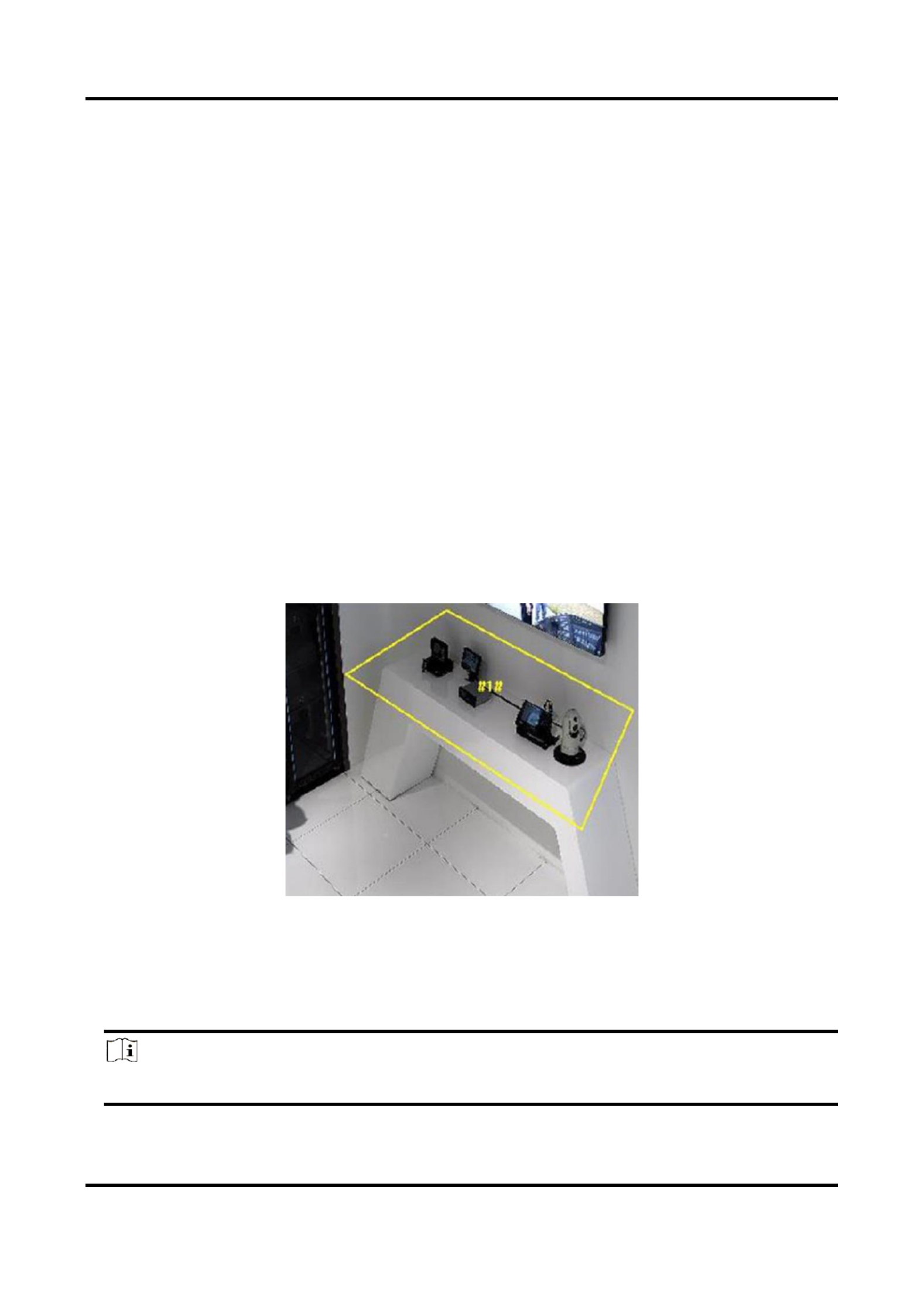
Network Camera User Manual
50
exhibits on display. If it occurs, the device can take linkage acons and the sta can take measures
to reduce property loss.
Steps
1. Go to Conguraon → Event → Smart Event → Object Removal Detecon.
2. Check . Enable
3. Select a . For the region sengs, see . Region Draw Area
4. Set the rule.
Sensivity
Range [1-100]. It stands for the percentage of the body part of an
acceptable target that leaves the pre-dened region.
Sensivity = 100 S1/ST*100 –
S1 stands for the target body part that leaves the pre-dened region.
ST stands for the complete target body.
Example: If you set the value as 60, a target is possible to be counted
as a removed object only when 40 percent body part of the target
leaves the region.
Threshold
Range [5-100s], the threshold for the me of the objects removed
from the region. If you set the value as 10, alarm is triggered aer the
object disappears from the region for 10s.
Figure 6-9 Set Rule
5. Oponal: Repeat the above steps to set more regions.
6. For the arming schedule sengs, see . For the linkage method sengs, see Set Arming Schedule
Linkage Method Sengs.
7. Click . Save
Note
The funcon is only supported by certain models. The actual display varies with the models.

Network Camera User Manual
51
6.2.12 Draw Area
This secon introduces the conguraon of area.
Steps
1. Click . Draw Area
2. Click on the live view to draw the boundaries of the detecon region, and right click to complete
drawing.
3. Click . Save
Note
Click to clear all pre-dened areas. Clear All
6.2.13 Set Size Filter
This part introduces the seng of size lter. Only the target whose size is between the minimum
value and maximum value is detected and triggers alarm.
Steps
1. Click , and drag the mouse in the live view to draw the maximum target size. Max. Size
2. Click , and drag the mouse in the live view to draw the minimum target size. Min. Size
3. Click . Save

Network Camera User Manual
52
Chapter 7 Network Sengs
7.1 TCP/IP
TCP/IP sengs must be properly congured before you operate the device over network. IPv4 and
IPv6 are both supported. Both versions can be congured simultaneously without conicng to
each other.
Go to for parameter sengs. Conguraon → Network → Basic Sengs → TCP/IP
NIC Type
Select a NIC (Network Interface Card) type according to your network condion.
IPv4
Two IPv4 modes are available.
DHCP
The device automacally gets the IPv4 parameters from the network if you check . The DHCP
device IP address is changed aer enabling the funcon. You can use SADP to get the device
IP address.
Note
The network that the device is connected to should support DHCP (Dynamic Host
Conguraon Protocol).
Manual
You can set the device IPv4 parameters manually. Input , , and IPv4 Address IPv4 Subnet Mask
IPv4 Default Gateway Test, and click to see if the IP address is available.
IPv6
Three IPv6 modes are available.
Route Adversement
The IPv6 address is generated by combining the route adversement and the device Mac
address.
Note
Route adversement mode requires the support from the router that the device is connected
to.
DHCP
The IPv6 address is assigned by the server, router, or gateway.

Network Camera User Manual
54
7.1.2 Mulcast Discovery
Check the , and then the online network camera can be automacally Enable Mulcast Discovery
detected by client soware via private mulcast protocol in the LAN.
7.2 SNMP
You can set the SNMP network management protocol to get the alarm event and excepon
messages in network transmission.
Before You Start
Before seng the SNMP, you should download the SNMP soware and manage to receive the
device informaon via SNMP port.
Steps
1. Go to the sengs page: Conguraon → Network → Advanced Sengs SNMP → .
2. Check , or . Enable SNMPv1 Enable SNMP v2c Enable SNMPv3
Note
The SNMP version you select should be the same as that of the SNMP soware.
And you also need to use the dierent version according to the security level required. SNMP v1
is not secure and SNMP v2 requires password for access. And SNMP v3 provides encrypon and
if you use the third version, HTTPS protocol must be enabled.
3. Congure the SNMP sengs.
4. Click . Save
7.3 Set SRTP
The Secure Real-me Transport Protocol (SRTP) is a Real-me Transport Protocol (RTP) internet
protocol, intended to provide encrypon, message authencaon and integrity, and replay aack
protecon to the RTP data in both unicast and mulcast applicaons.
Steps
1. Go to . Conguraon → Network → Advanced Sengs → SRTP
2. Select . Server Cercate
3. Select . Encrypted Algorithm
4. Click . Save
Note
● Only certain device models support this funcon.
● If the funcon is abnormal, check if the selected cercate is abnormal in cercate
management.

Network Camera User Manual
55
7.4 Port Mapping
By seng port mapping, you can access devices through the specied port.
Before You Start
When the ports in the device are the same as those of other devices in the network, refer to Port
to modify the device ports.
Steps
1. Go to . Conguraon → Network → Basic Sengs → NAT
2. Select the port mapping mode.
Auto Port Mapping
Refer to for detailed informaon. Set Auto Port Mapping
Manual Port
Mapping
Refer to for detailed informaon. Set Manual Port Mapping
3. Click . Save
7.4.1 Set Auto Port Mapping
Steps
1. Check , and choose a friendly name for the camera, or you can use the default Enable UPnP™
name.
2. Select the port mapping mode to . Auto
3. Click . Save
Note
UPnP™ funcon on the router should be enabled at the same me.
7.4.2 Set Manual Port Mapping
Steps
1. Check , and choose a friendly name for the device, or you can use the default Enable UPnP™
name.
2. Select the port mapping mode to , and set the external port to be the same as the Manual
internal port.
3. Click . Save
What to do next
Go to the router port mapping sengs interface and set the port number and IP address to be the
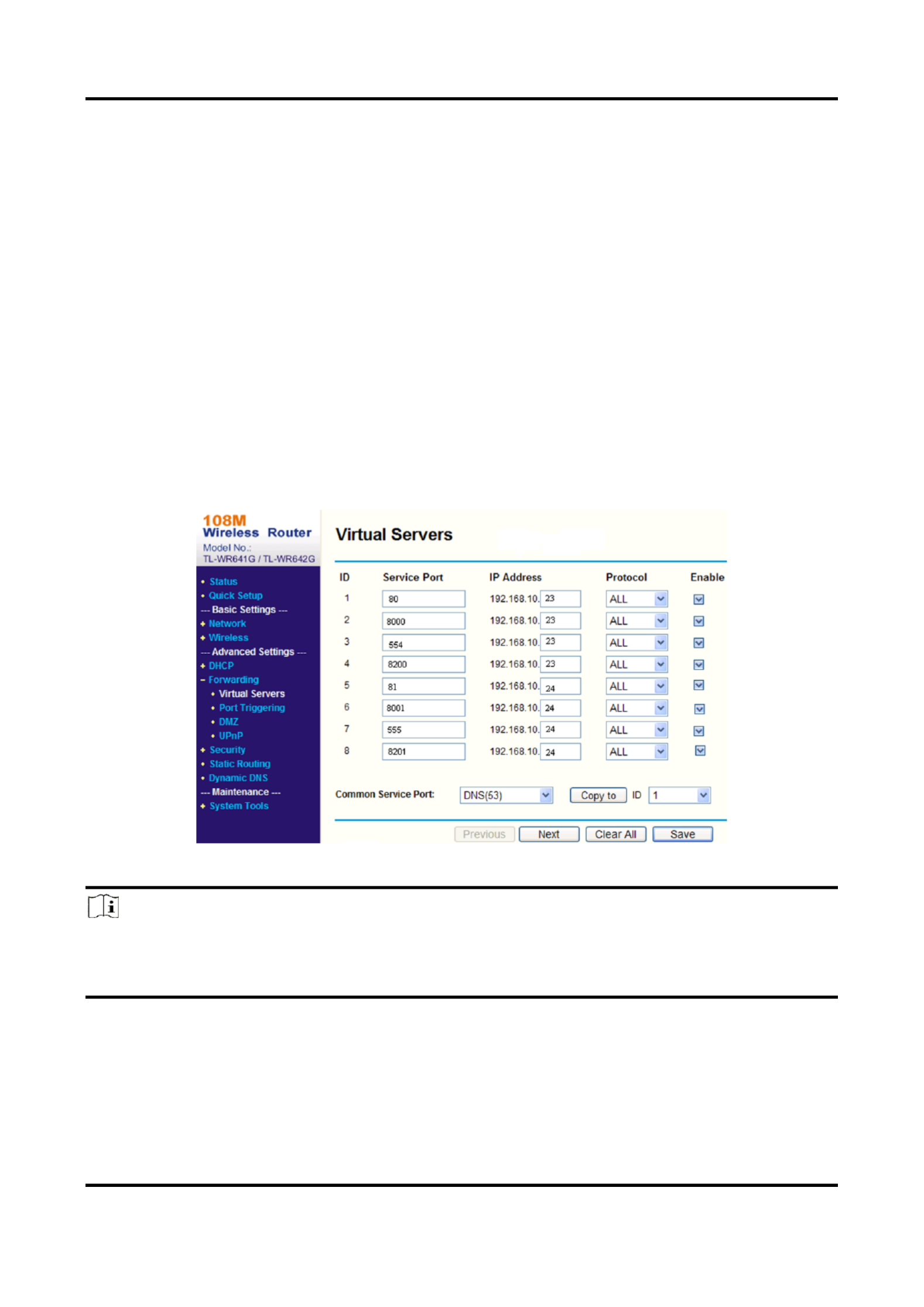
Network Camera User Manual
56
same as those on the device. For more informaon, refer to the router user manual.
7.4.3 Set Port Mapping on Router
The following sengs are for a certain router. The sengs vary depending on dierent models of
routers.
Steps
1. Select the . WAN Connecon Type
2. Set the and other network parameters of the route IP Address, Subnet Mask r.
3. Go to Forwarding → Virtual Severs Port Number IP Address, and input the and .
4. Click . Save
Example
When the cameras are connected to the same router, you can congure the ports of a camera as
80, 8000, and 554 with IP address 192.168.1.23, and the ports of another camera as 81, 8001, 555,
8201 with IP 192.168.1.24.
Figure 7-1 Port Mapping on Router
Note
The port of the network camera cannot conict with other ports. For example, some web
management port of the router is 80. Change the camera port if it is the same as the management
port.

Network Camera User Manual
57
7.5 Port
The device port can be modied when the device cannot access the network due to port conicts.
Cauon
Do not modify the default port parameters at will, otherwise the device may be inaccessible.
Go to for port sengs. Conguraon → Network → Basic Sengs → Port
HTTP Port
It refers to the port through which the browser accesses the device. For example, when the
HTTP Port is modied to 81, you need to enter in the browser for login. hp://192.168.1.64:81
HTTPS Port
It refers to the port through which the browser accesses the device with cercate. Cercate
vericaon is required to ensure the secure access.
RTSP Port
It refers to the port of real-me streaming protocol.
SRTP Por t
It refers to the port of secure real-me transport protocol.
Server Port
It refers to the port through which the client adds the device.
Enhanced SDK Service Port
It refers to the port through which the client adds the device. Cercate vericaon is required
to ensure the secure access.
WebSocket Port
TCP-based full-duplex communicaon protocol port for plug-in free preview.
WebSockets Port
TCP-based full-duplex communicaon protocol port for plug-in free preview. Cercate
vericaon is required to ensure the secure access.
Note
● Enhanced SDK Service Port, WebSocket Port, and WebSockets Port are only supported by
certain models.
● For device models that support that funcon, go to Conguraon → Network → Advanced
Sengs Network Service → to enable it.

Network Camera User Manual
58
7.6 Access to Device via Domain Name
You can use the Dynamic DNS (DDNS) for network access. The dynamic IP address of the device
can be mapped to a domain name resoluon server to realize the network access via domain
name.
Before You Start
Registraon on the DDNS server is required before conguring the DDNS sengs of the device.
Steps
1. Refer to to set DNS parameters. TCP/IP
2. Go to the DDNS sengs page: . Conguraon → Network → Basic Sengs → DDNS
3. Check and select . Enable DDNS DDNS type
DynDNS
Dynamic DNS server is used for domain name resoluon.
NO-IP
NO-IP server is used for domain name resoluon.
4. Input the domain name informaon, and click . Save
5. Check the device ports and complete port mapping. Refer to Port to check the device port , and
refer to for port mapping sengs. Port Mapping
6. Access the device.
By Browsers
Enter the domain name in the browser address bar to access the
device.
By Client Soware
Add domain name to the client soware. Refer to the client manual
for specic adding methods.
7.7 Access to Device via PPPoE Dial Up Connecon
This device supports the PPPoE auto dial-up funcon. The device gets a public IP address by ADSL
dial-up aer the device is connected to a modem. You need to congure the PPPoE parameters of
the device.
Steps
1. Go to . Conguraon → Network → Basic Sengs → PPPoE
2. Check . Enable PPPoE
3. Set the PPPoE parameters.
Dynamic IP
Aer successful dial-up, the dynamic IP address of the WAN is displayed.
User Name
User name for dial-up network access.

Network Camera User Manual
59
Password
Password for dial-up network access.
Conrm
Input your dial-up password again.
4. Click . Save
5. Access the device.
By Browsers
Enter the WAN dynamic IP address in the browser address bar to
access the device.
By Client Soware
Add the WAN dynamic IP address to the client soware. Refer to the
client manual for details.
Note
The obtained IP address is dynamically assigned via PPPoE, so the IP address always changes
aer reboong the camera. To solve the inconvenience of the dynamic IP, you need to get a
domain name from the DDNS provider (e.g. DynDns.com). Refer to Access to Device via Domain
Name for detail informaon.
7.8 Wireless Dial
Data of audio, video and image can be transferred via 3G/4G wireless network.
Note
The funcon is only supported by certain device models.
7.8.1 Set Wireless Dial
The built-in wireless module oers dial-up access to the Internet for the device.
Before You Start
Get a SIM card, and acvate 3G/4G services. Insert the SIM card to the corresponding slot.
Steps
1. Go to Conguraon → Network → Advanced Sengs → Wireless Dial.
2. Check to enable the funcon.
3. Click to congure and save the parameters. Dial Parameters
4. Click . See for detailed informaon. Dial Plan Set Arming Schedule
5. Oponal: Set . See for detailed informaon. Allowlist Set Allowlist
6. Click . Dial Status

Network Camera User Manual
60
Click Refresh
Refresh the dial status.
Click Disconnect
Disconnect the 3G/4G wireless network.
When the turns to , it means a successful dial. Dial Status Connected
7. Access the device via the of the computer in the network. IP Address
– Input the IP address in the browser to access the device.
– Add the device in client applicaon. Select , and input IP address and other IP/Domain
parameters to access the device.
7.8.2 Set Allowlist
Add the mobile phone number of administrator to the allowlist in order to receive alarm message
from the device.
Steps
1. Go to allowlist sengs page: Conguraon → Advanced Conguraon → Wireless Dial →
Allowlist.
2. Check . Enable SMS Alarm
3. Click in the allowlist.
1) Input the mobile phone number to receive alarm message.
2) Check . Reboot via SMS
3) Select the certain events, and the mobile phone can receive the alarm message when the
event happens.
4) Click . Save
5) Oponal: Repeat the steps above to set mulple recipients.
Modify the allowlist parameters.
Delete the allowlist that already set.
Send Test SMS
Send a message to the mobile phone for test.
4. Click . Save
7.9 Wi- Fi
Connect the device to wireless network by seng Wi-Fi parameters.
Note
This funcon is only supported by certain device models.

Network Camera User Manual
62
When you use WebSockets, select the . Server Cercate
Note
Complete cercate management before selecng server cercate. Refer to Cercate
Management for detailed informaon.
SDK Service & Enhanced SDK Service
Check to add the device to the client soware with SDK protocol. Enable SDK Service
Check to add the device to the client soware with SDK over Enable Enhanced SDK Service
TLS protocol.
When you use Enhanced SDK Service, select the . Server Cercate
Note
● Complete cercate management before selecng server cercate. Refer to Cercate
Management for detailed informaon.
● When set up connecon between the device and the client soware, it is recommended to
use Enhanced SDK Service and set the communicaon in Arming Mode to encrypt the data
transmission. See the user manual of the client soware for the arming mode sengs.
TLS (Transport Layer Security)
The device oers TLS1.1 and TLS1.2. Enable one or more protocol versions according to your
need.
Bonjour
Uncheck to disable the protocol.
3. Click . Save
7.11 Set Open Network Video Interface
If you need to access the device through Open Network Video Interface protocol, you can
congure the user sengs to enhance the network security.
Steps
1. Go to Conguraon → Network → Advanced Sengs → Integraon Protocol.
2. Check . Enable Open Network Video Interface
3. Click to congure the Open Network Video Interface user. Add
Delete
Delete the selected Open Network Video Interface user.
Modify
Modify the selected Open Network Video Interface user.
4. Click . Save

Network Camera User Manual
63
5. Oponal: Repeat the steps above to add more Open Network Video Interface users.
7.12 Set ISUP
When the device is registered on ISUP plaorm (formerly called Ehome), you can visit and manage
the device, transmit data, and forward alarm informaon over public network.
Steps
1. Go to Conguraon → Network → Advanced Sengs → Platform Access.
2. Select as the plaorm access mode. ISUP
3. Select . Enable
4. Select a protocol version and input related parameters.
5. Click . Save
Register status turns to when the funcon is correctly set. Online
7.13 Set Alarm Server
The device can send alarms to desnaon IP address or host name through HTTP, HTTPS, or ISUP
protocol. The desnaon IP address or host name should support HTTP, HTTP, or ISUP data
transmission.
Steps
1. Go to Conguraon → Network → Advanced Sengs → Alarm Server.
2. Enter , , and . Desnaon IP or Host Name URL Port
3. Select . Protocol
Note
HTTP, HTTPS, and ISUP are selectable. It is recommended to use HTTPS, as it encrypts the data
transmission during communicaon.
4. Click to check if the IP or host is available. Test
5. Click . Save
7.14 Access Camera via Hik-Connect
Hik-Connect is an applicaon for mobile devices. Using the App, you can view live image, receive
alarm nocaon and so on.
Before You Start
Connect the camera to network with network cables.
Steps
1. Get and install Hik-Connect applicaon by the following ways.

Network Camera User Manual
64
Visit to download the applicaon according to your mobile phone hps://appstore.hikvision.com
system.Visit the ocial site of our company. Then go to Support → Tools → Hikvision App
Store.Scan the QR code below to download the applicaon.
Note
If errors like "Unknown app" occur during the installaon, solve the problem in two ways.
Visit to refer to the troubleshoong.Visit hps://appstore.hikvision.com/stac/help/index.html
hps://appstore.hikvision.com/, and click at the upper right corner of the Installaon Help
interface to refer to the troubleshoong.
2. Start the applicaon and register for a Hik-Connect user account.
3. Log in aer registraon.
4. In the app, tap "+" on the upper-right corner and then scan the QR code of the camera to add
the camera. You can nd the QR code on the camera or on the cover of the Quick Start Guide of
the camera in the package.
5. Follow the prompts to set the network connecon and add the camera to your Hik-Connect
account.
For detailed informaon, refer to the user manual of the Hik-Connect app.
7.14.1 Enable Service on Camera Hik-Connect
Hik-Connect service should be enabled on your camera before using the service.
You can enable the service through SADP soware or Web browser.
Enable Service via Web Browser Hik-Connect
Follow the following steps to enable Hik-Connect Service via Web Browser.
Before You Start
You need to acvate the camera before enabling the service.
Steps
1. Access the camera via web browser.
2. Enter plaorm access conguraon interface. Conguraon → Network → Advanced Sengs
→ Plaorm Access
3. Select Hik-Connect as the . Plaorm Access Mode
4. Check . Enable

Network Camera User Manual
66
interface to refer to the troubleshoong.
2. Start the applicaon and register for a Hik-Connect user account.
3. Log in aer registraon.
7.14.3 Add Camera to Hik-Connect
Steps
1. Connect your mobile device to a Wi-Fi.
2. Log into the Hik-Connect app.
3. In the home page, tap "+" on the upper-right corner to add a camera.
4. Scan the QR code on camera body or on the cover. Quick Start Guide
Note
If the QR code is missing or too blur to be recognized, you can also add the camera by inpung
the camera's serial number.
5. Input the vericaon code of your camera.
Note
● The required vericaon code is the code you create or change when you enable Hik-Connect
service on the camera.
● If you forget the vericaon code, you can check the current vericaon code on Plaorm
Access conguraon page via web browser.
6. Tap buon in the popup interface. Connect to a Network
7. Choose or according to your camera funcon. Wired Connecon Wireless Connecon
Wireless Connecon
Input the Wi-Fi password that your mobile phone has connected to,
and tap to start the Wi-Fi connecon process. (Locate the Next
camera within 3 meters from the router when seng up the Wi-Fi.)
Wired Connecon
Connect the camera to the router with a network cable and tap
Connected in the result interface.
Note
The router should be the same one which your mobile phone has connected to.
8. Tap in the next interface to nish adding. Add
For detailed informaon, refer to the user manual of the Hik-Connect app.

Network Camera User Manual
67
Chapter 8 Arming Schedule and Alarm Linkage
Arming schedule is a customized me period in which the device performs certain tasks. Alarm
linkage is the response to the detected certain incident or target during the scheduled me.
8.1 Set Arming Schedule
Set the valid me of the device tasks.
Steps
1. Click . Arming Schedule
2. Drag the me bar to draw desired valid me.
Note
Up to 8 periods can be congured for one day.
3. Adjust the me period.
– Click on the selected me period, and enter the desired value. Click . Save
– Click on the selected me period. Drag the both ends to adjust the me perio d.
– Click on the selected me period, and drag it on the me bar.
4. Oponal: Click to copy the same sengs to other days. Copy to...
5. Click . Save
8.2 Linkage Method Sengs
You can enable the linkage funcons when an event or alarm occurs.
8.2.1 Trigger Alarm Output
If the device has been connected to an alarm output device, and the alarm output No. has been
congured, the device sends alarm informaon to the connected alarm output device when an
alarm is triggered.
Steps
1. Go to Conguraon → Event → Basic Event → Alarm Output.
2. Set alarm output parameters.
Automac Alarm
For the informaon about the conguraon, see . Automac Alarm
Manual Alarm
For the informaon about the conguraon, see . Manual Alarm
3. Click . Save

Network Camera User Manual
69
Refer to for memory card storage conguraon. Set New or Unencrypted Memory Card
8.2.3 Send Email
Check , and the device sends an email to the designated addresses with alarm Send Email
informaon when an alarm event is detected.
For email sengs, refer to . Set Email
Set Email
When the email is congured and is enabled as a linkage method, the device sends an Send Email
email nocaon to all designated receivers if an alarm event is detected.
Before You Start
Set the DNS server before using the Email funcon. Go to Conguraon → Network → Basic
Sengs TCP/IP → for DNS sengs.
Steps
1. Go to email sengs page: . Conguraon → Network → Advanced Sengs → Email
2. Set email parameters.
1) Input the sender's email informaon, including the , Sender's Address SMTP Server, and
SMTP Port.
2) Oponal: If your email server requires authencaon, check and input your Authencaon
user name and password to log in to the server.
3) Set the . E-mail Encrypon
● When you select or , and disable STARTTLS, emails are sent aer encrypted by SSL SSL TLS
or TLS. The SMTP port should be set as 465.
● When you select or and , emails are sent aer encrypted by SSL TLS Enable STARTTLS
STARTTLS, and the SMTP port should be set as 25.
Note
If you want to use STARTTLS, make sure that the protocol is supported by your email server.
If you check the while the protocol is not supported by your email sever, Enable STARTTLS
your email is sent with no encrypon.
4) Oponal: If you want to receive nocaon with alarm pictures, check . The Aached Image
nocaon email has 3 aached alarm pictures about the event with congurable image
capturing interval.
5) Input the receiver's informaon, including the receiver's name and address.
6) Click to see if the funcon is well congured. Test
3. Click . Save

Network Camera User Manual
70
8.2.4 Nofy Surveillance Center
Check , the alarm information is uploaded to the surveillance center Nofy Surveillance Center
when an alarm event is detected.
8.2.5 Trigger Recording
Check , and the device records the video about the detected alarm event. Trigger Recording
For recording settings, refer to Video Recording and Picture Capture
8.2.6 Flashing Light
After enabling and setting the , the light flashes when Flashing Light Flashing Light Alarm Output
an alarm event is detected.
Set Flashing Alarm Light Output
When events occur, the flashing light on the device can be triggered as an alarm.
Steps
1. Go t o Conguraon → Event → Basic Event → Flashing Alarm Light Output.
2. Set and . Flashing Duraon, Flashing Frequency Brightness
Flashing Duraon
The time that the flashing lasts when one alarm happens.
Flashing Frequency
The rate at which the light flashes. High frequency, medium frequency, low frequency, and
normally on are selectable.
Brightness
The brightness of the light.
3. Set the arming schedule. See for details. Set Arming Schedule
4. Click . Save
Note
Only certain device models support the function.
8.2.7 Audible Warning
After enabling and setting , the built-in speaker of the Audible Warning Audible Alarm Output
device or connected external speaker plays warning sounds when an alarm happens.
For audible alarm output settings, refer to . Set Audible Alarm Output

Network Camera User Manual
71
Note
The function is only supported by certain camera models.
Set Audible Alarm Output
When the device detects targets in the detection area, audible alarm can be triggered as a
warning.
Steps
1. Go to Configuration → Event → Basic Event → Audible Alarm Output.
2. Select and set related parameters. Sound Type
– Select and set the alarm times you need. Prompt
– Select and its contents. Set the alarm times you need. Warning
– Select . You can select a custom audio file from the drop-down list. If no file is Custom Audio
available, you can click to upload an audio file that meets the requirement. Up to three Add
audio files can be uploaded.
3. Optional: Click to play the selected audio file on the device. Test
4. Set arming schedule for audible alarm. See for details. Set Arming Schedule
5. Click . Save
Note
The function is only supported by certain device models.

Network Camera User Manual
72
Chapter 9 System and Security
It introduces system maintenance, system settings and security management, and explains how to
configure relevant parameters.
9.1 View Device Information
You can view device information, such as Device No., Model, Serial No. and Firmware Version.
Enter to view the device Configuration → System → System Settings → Basic Information
information.
9.2 Search and Manage Log
Log helps locate and troubleshoot problems.
Steps
1. Go to Configuration → System → Maintenance → Log.
2. Set search conditions , , , and Major Type Minor Type Start Time End Time.
3. Click Search.
The matched log files will be displayed on the log list.
4. Optional: Click to save the log files in your computer. Export
9.3 Simultaneous Login
The administrator can set the maximum number of users logging into the system through web
browser simultaneously.
Go to , click and set . Configuration → System → User Management General Simultaneous Login
9.4 Import and Export Configuration File
It helps speed up batch configuration on other devices with the same parameters.
Enter . Choose device Configuration → System → Maintenance → Upgrade & Maintenance
parameters that need to be imported or exported and follow the instructions on the interface to
import or export configuration file.
9.5 Export Diagnose Information
Diagnose information includes running log, system information, hardware information.
Go to . Check desired Configuration → System → Maintenance → Upgrade & Maintenance

Network Camera User Manual
73
diagnose information and click to export corresponding diagnose Diagnose Information
information of the device.
9.6 Reboot
You can reboot the device via browser.
Go to , and click Configuration → System → Maintenance → Upgrade & Maintenance Reboot.
9.7 Restore and Default
Restore and Default helps restore the device parameters to the default settings.
Steps
1. Go to Configuration → System → Maintenance → Upgrade & Maintenance.
2. Click or according to your needs. Restore Default
Restore
Reset device parameters, except user information, IP parameters and
video format to the default settings.
Default
Reset all the parameters to the factory default.
Note
Be careful when using this function. After resetting to the factory
default, all the parameters are reset to the default settings.
9.8 Upgrade
Before You Start
You need to obtain the correct upgrade package.
Caution
DO NOT disconnect power during the process, and the device reboots automatically after upgrade.
Steps
1. Go to Configuration → System → Maintenance → Upgrade & Maintenance.
2. Choose one method to upgrade.
Firmware
Locate the exact path of the upgrade file.

Network Camera User Manual
74
Firmware Directory
Locate the directory which the upgrade file belongs to.
3. Click to select the upgrade file. Browse
4. Click . Upgrade
9.9 View Open Source Software License
Go to , and click . Configuration → System → System Settings → About Device View Licenses
9.10 Wiegand
Note
This function is only supported by certain camera models.
Check and select the protocol. The default protocol is SHA-1 26bit. Enable
If enabled, the recognized license plate number will be output via the selected Wiegand protocol.
9.11 Metadata
Metadata is the raw data that the camera collects before algorithm processing. It provide the
option to users to explore various data usages.
Go to to enable metadata uploading of the desired Configuration → System → Metadata Settings
function.
Smart Event
The metadata of the smart event includes the target ID, target coordinate, time, etc.
9.12 Time and Date
You can configure time and date of the device by configuring time zone, time synchronization and
Daylight Saving Time (DST).
9.12.1 Synchronize Time Manually
Steps
1. Go to . Configuration → System → System Settings → Time Settings
2. Select . Time Zone
3. Click . Manual Time Sync.
4. Choose one time synchronization method.
– Select , and manually input or select date and time from the pop-up calendar. Set Time

Network Camera User Manual
76
4. Click . Save
9.13 Set RS- 485
RS-485 is used to connect the device to external device. You can use RS-485 to transmit the data
between the device and the computer or terminal when the communication distance is too long.
Before You Start
Connect the device and computer or termial with RS-485 cable.
Steps
1. Go to . Configuration → System → System Settings → RS-485
2. Set the RS-485 parameters.
Note
You should keep the parameters of the device and the computer or terminal all the same.
3. Click . Save
9.14 Set RS- 232
RS-232 can be used to debug device or access peripheral device. RS-232 can realize
communication between the device and computer or terminal when the communication distance
is short.
Before You Start
Connect the device to computer or terminal with RS-232 cable.
Steps
1. Go to . Configuration → System → System Settings → RS-232
2. Set RS-232 parameters to match the device with computer or terminal.
3. Click . Save
9.15 Power Consumption Mode
It is used to switch the power consumption when the device is working.
Note
The function is only supported by certain camera models.
Go to , select the Configuration → System → System Settings → Power Consumption Mode
desired power consumption mode.
Full Consumption Mode

Network Camera User Manual
78
IR Mode
IR light is enabled.
White Light Mode
White light is enabled.
Mix Mode
Both IR light and white light are enabled.
Off
Supplement light is disabled.
Brightness Adjustment Mode
Auto
The brightness adjusts according to the actual environment automatically.
Manual
You can drag the slider or set value to adjust the brightness.
9.16.2 Heater
You can enable heater to remove fog around the lens of the device.
Go to and select the mode as Configuration → System → System Settings → External Device
required.
9.17 Security
You can improve system security by setting security parameters.
9.17.1 Authentication
You can improve network access security by setting RTSP and WEB authentication.
Go to to choose authentication protocol Configuration → System → Security → Authentication
and method according to your needs.
RTSP Authentication
Digest and digest/basic are supported, which means authentication information is needed when
RTSP request is sent to the device. If you select , it means the device supports digest/basic
digest or basic authentication. If you select , the device only supports digest digest
authentication.
RTSP Digest Algorithm
MD5, SHA256 and MD5/SHA256 encrypted algorithm in RTSP authentication. If you enable the
digest algorithm except for MD5, the third-party platform might not be able to log in to the
device or enable live view because of compatibility. The encrypted algorithm with high strength

Network Camera User Manual
79
is recommended.
WEB Authentication
Digest and digest/basic are supported, which means authentication information is needed when
WEB request is sent to the device. If you select , it means the device supports digest digest/basic
or basic authentication. If you select , the device only supports digest authentication. digest
WEB Digest Algorithm
MD5, SHA256 and MD5/SHA256 encrypted algorithm in WEB authentication. If you enable the
digest algorithm except for MD5, the third-party platform might not be able to log in to the
device or enable live view because of compatibility. The encrypted algorithm with high strength
is recommended.
Note
Refer to the specific content of protocol to view authentication requirements.
9.17.2 Set IP Address Filter
IP address filter is a tool for access control. You can enable the IP address filter to allow or forbid
the visits from the certain IP addresses.
IP address refers to IPv4.
Steps
1. Go to Configuration → System → Security → IP Address Filter.
2. Check . Enable IP Address Filter
3. Select the type of IP address filter.
Forbidden
IP addresses in the list cannot access the device.
Allowed
Only IP addresses in the list can access the device.
4. Edit the IP address filter list.
Add
Add a new IP address or IP address range to the list.
Modify
Modify the selected IP address or IP address range in the list.
Delete
Delete the selected IP address or IP address range in the list.
5. Click . Save

Network Camera User Manual
80
9.17.3 Set HTTPS
HTTPS is a network protocol that enables encrypted transmission and identity authentication,
which improves the security of remote access.
Steps
1. Go to Configuration → Network → Advanced Settings → HTTPS.
2. Check to access the camera via HTTP or HTTPS protocol. Enable
3. Check to access the camera only via HTTPS protocol. Enable HTTPS Browsing
4. Select the Server Certificate.
5. Click Save.
Note
If the function is abnormal, check if the selected certificate is abnormal in Certificate
Management.
9.17.4 Set QoS
QoS (Quality of Service) can help improve the network delay and network congestion by setting
the priority of data sending.
Note
QoS needs support from network device such as router and switch.
Steps
1. Go to . Configuration → Network → Advanced Configuration → QoS
2. Set , and Video/Audio DSCP Alarm DSCP Management DSCP.
Note
Network can identify the priority of data transmission. The bigger the DSCP value is, the higher
the priority is. You need to set the same value in router while configuration.
3. Click Save.
9.17.5 Set IEEE 802.1X
IEEE 802.1x is a port-based network access control. It enhances the security level of the
LAN/WLAN. When devices connect to the network with IEEE 802.1x standard, the authentication is
needed.
Go to , and enable the function. Configuration → Network → Advanced Settings → 802.1X
Set and according to router information. Protocol EAPOL Version

Network Camera User Manual
81
Protocol
EAP-LEAP, EAP-TLS, and EAP-MD5 are selectable
EAP-LEAP and EAP-MD5
If you use EAP-LEAP or EAP-MD5, the authentication server must be configured. Register a
user name and password for 802.1X in the server in advance. Input the user name and
password for authentication.
EAP-TLS
If you use EAP-TLS, input Identify, Private Key Password, and upload CA Certificate, User
Certificate and Private Key.
EAPOL Version
The EAPOL version must be identical with that of the router or the switch.
9.17.6 Control Timeout Settings
If this function is enabled, you will be logged out when you make no operation (not including
viewing live image) to the device via web browser within the set timeout period.
Go to to complete settings. Configuration → System → Security → Advanced Security
9.17.7 Search Security Audit Logs
You can search and analyze the security log files of the device so as to find out the illegal intrusion
and troubleshoot the security events.
Steps
Note
This function is only supported by certain camera models.
1. Go to . Configuration → System → Maintenance → Security Audit Log
2. Select log types, , and . Start Time End Time
3. Click . Search
The log files that match the search conditions will be displayed on the Log List.
4. Optional: Click to save the log files to your computer. Export
9.17.8 Security Reinforcement
Security reinforce is a solution to enhance network security. With the function enabled, risky
functions, protocols, ports of the device are disabled and more secured alternative functions,
protocols and ports are enabled.
Go to . Check , Configuration → System → Security → Advanced Security Security Reinforcement
and click . Save

Network Camera User Manual
82
9.17.9 SSH
Secure Shell (SSH) is a cryptographic network protocol for operating network services over an
unsecured network.
The SSH function is disabled by default.
Caution
Use the function with caution. The security risk of device internal information leakage exists when
the function is enabled.
9.18 Certificate Management
It helps to manage the server/client certificates and CA certificate, and to send an alarm if the
certificates are close to expiry date, or are expired/abnormal.
9.18.1 Create Self-signed Certificate
Steps
1. Click . Create Self-signed Certificate
2. Follow the prompt to enter , , and other Certificate ID, Country Hostname/IP Validity
parameters.
Note
The certificate ID should be digits or letters and be no more than 64 characters.
3. Click . OK
4. Optional: Click to export the certificate, or click to delete the certificate to Export Delete
recreate a certificate, or click to view the certificate details. Certificate Properties
9.18.2 Create Certificate Request
Before You Start
Select a self-signed certificate.
Steps
1. Click . Create Certificate Request
2. Enter the related information.
3. Click . OK

Network Camera User Manual
83
9.18.3 Import Certificate
Steps
1. Click . Import
2. Click Create Certificate Request.
3. Enter the . Certificate ID
4. Click to select the desired server/client certificate. Browser
5. Select the desired import method and enter the required information.
6. Click . OK
7. Optional: Click to export the certificate, or click to delete the certificate to Export Delete
recreate a certificate, or click to view the certificate details. Certificate Properties
Note
● Up to 16 certificates are allowed.
● If certain functions are using the certificate, it cannot be deleted.
● You can view the functions that are using the certificate in the functions column.
● You cannot create a certificate that has the same ID with that of the existing certificate and
import a certificate that has the same content with that of the existing certificate.
9.18.4 Install Server/Client Certificate
Steps
1. Go to Configuration → System → Security → Certificate Management.
2. Click , and to install Create Self-signed Certificate Create Certificate Request Import
server/client certificate.
Create self-signed
certificate
Refer to Create Self-signed Certificate
Create certificate
request
Refer to Create Certificate Request
Import Certificate
Refer to Import Certificate
9.18.5 Install CA Certificate
Steps
1. Click . Import
2. Enter the . Certificate ID
3. Click to select the desired server/client certificate. Browser
4. Select the desired import method and enter the required information.

Network Camera User Manual
84
5. Click . OK
Note
Up to 16 certificates are allowed.
9.18.6 Enable Certificate Expiration Alarm
Steps
1. Check . If enabled, you will receive an email or the camera Enable Certificate Expiration Alarm
links to the surveillance center that the certificate will expire soon, or is expired or abnormal.
2. Set the , and . Remind Me Before Expiration (day) Alarm Frequency (day) Detection Time (hour)
Note
● If you set the reminding day before expiration to 1, then the camera will remind you the day
before the expiration day. 1 to 30 days are available. Seven days is the default reminding
days.
● If you set the reminding day before expiration to 1, and the detection time to 10:00, and the
certificate will expire in 9:00 the next day, the camera will remind you in 10:00 the first day.
3. Click . Save
9.19 User and Account
9.19.1 Set User Account and Permission
The administrator can add, modify, or delete other accounts, and grant different permission to
different user levels.
Caution
To increase security of using the device on the network, please change the password of your
account regularly. Changing the password every 3 months is recommended. If the device is used in
high-risk environment, it is recommended that the password should be changed every month or
week.
Steps
1. Go to Configuration → System → User Management User Management → .
2. Click . Enter , select , and enter . Assign remote permission to Add User Name Level Password
users based on needs.

Network Camera User Manual
86
Chapter 10 Allocate VCA Resource
VCA resource offers you options to enable certain VCA functions according to actual needs. It
helps allocate more resources to the desired functions.
Steps
1. Go to . Configuration → System → System Settings → VCA Resource
2. Select desired VCA function.
3. Save the settings.
Note
Some VCA functions are mutually exclusive. When certain function or functions are selected and
saved, others will not be hidden.
10.1 Switch Smart Mode
You can enable the smart function select the detection target as required.
Steps
1. Go to Configuration → System → System Settings → Smart Mode Switch。
2. Select the desired smart mode.
Table 10-1 Smart function of the smart mode
Smart Mode
Detection Target
Smart Function
Capture Mode
The device captures the target in the detection area and upload the captured image. You can
select the targets to capture as required.
Face
Face Capture
Motor Vehicles
Road Traffic
Other Combinations
Multi-Target-Type Detection
Comparison Mode
The device recognizes, captures and compares the targets in the rule region, and collects the
target attribute and models for the target.
Face
Face Capture
Face Comparison and
Modeling

Network Camera User Manual
87
Face+Human Body
Multi-Target-Type Detection
Face Comparison and
Modeling
Pattern Mode
The devices link the captured faces, human bodies and vehicles information of the different
channels and display the targets patterns.
Channel 1: Face
Channel 2: Face+Human
Body+Motor
Vehicles+Non-Motor Vehicles
Pattern Linkage
Face Capture
Multi-Target-Type Detection
Face Comparison and
Modeling
Channel 1: Face+Human Body
Channel 2: Face+Human
Body+Motor
Vehicles+Non-Motor Vehicles
Pattern
LinkageMulti-Target-Type
Detection
Face Comparison and
Modeling
Monitoring
-
3. Click . Save
Note
● In comparison mode, only channel 2 supports monitoring mode.
● The pattern mode is only supported by the 2-channel devices. Only channel 1 supports
human body detection.
10.2 Face Capture
The device can capture the face that appears in the configured area, and the face information will
be uploaded with the captured picture as well.
Note
● For device that supports face capture, you need to enable the function in . Refer VCA Resource
to for details. Allocate VCA Resource
● Face capture is only supported by certain models.
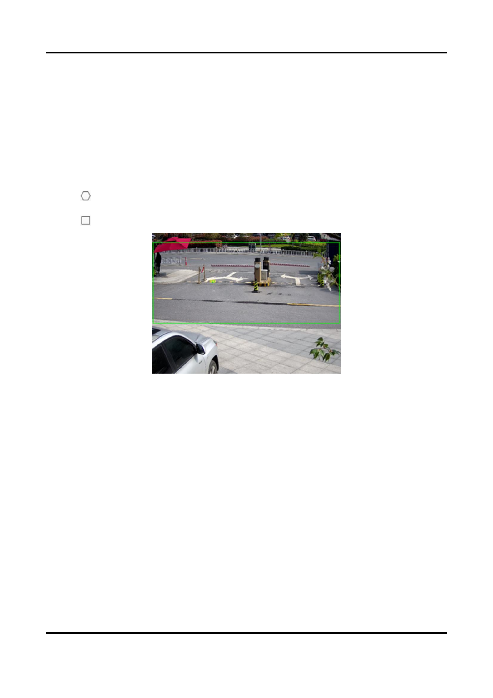
Network Camera User Manual
88
10.2.1 Set Face Capture
The face that appears in the configured area can be captured.
Before You Start
To enable the function, go to and select . VCA Resource Face Capture
Steps
1. Go to . Configuration → Face Capture
2. For shield region settings, refer to . Set Shield Region
3. Select and check . Rule Rule
4. Click to draw the detection area. It is recommended that the drawn area occupies 1/2 to
2/3 of the live view image.
5. Click and draw a rectangle based on the pupil distance of the face on the live view.
Figure 10-1 Set face capture
The device will detect whether there is a human face in the area by the set minimum pupil
distance.
6. For the arming schedule settings, refer to . For the linkage method settings, Set Arming Schedule
refer to . Linkage Method Settings
7. Click . Save
8. For overlay and capture settings, refer to . For advanced parameters Overlay and Capture
settings, refer to . Face Capture Algorithms Parameters
Result
You can view and download captured face images in . Refer to Picture View and Download Picture
for details.
10.2.2 Overlay and Capture
Choose to configure capture parameters and the information you want to display on stream and
picture.
Display VCA info. on Stream

Network Camera User Manual
90
The sensivity to idenfy a target. The higher the value is, the easier a face will be recognized,
and the higher possibility of misinformaon would be. The default value of 3 is recommended.
Capture Parameters
Best Shot
The best shot aer target leave the detecon area.
Capture Times
It refers to the capture mes a face will be captured during its stay in the congured area. The
default value is 1.
Capture Interval
The frame interval to capture a picture. If you set the value as 1, which is the default value, it
means the camera captures the face in every frame.
Capture Threshold
It stands for the quality of face to trigger capture and alarm. Higher value means beer quality
should be met to trigger capture and alarm.
Quick Shot
You can dene quick shot threshold and max. capture interval.
Quick Shot Threshold
It stands for the quality of face to trigger quick shot.
Face Exposure
Check the checkbox to enable the face exposure.
Reference Brightness
The reference brightness of a face in the face exposure mode. If a face is detected, the camera
adjusts the face brightness according to the value you set. The higher the value, the brighter the
face is.
Minimum Duraon
The minimum duraon of the camera exposures the face. The default value is 1 minute.
Note
If the face exposure is enabled, please make sure the WDR funcon is disabled, and the manual
iris is selected.
Face Filtering Time
It means the me interval between the camera detecng a face and taking a capture acon. If
the detected face stays in the scene for less than the set ltering me, capture will not be
triggered. For example, if the face ltering me is set as 5 seconds, the camera will capture the
detected face when the face keeps staying in the scene for 5 seconds.

Network Camera User Manual
91
Note
The face ltering me (longer than 0s) may increase the possibility of the actual capture mes
less than the set value above.
Restore Default
Click to restore all the sengs in advanced conguraon to the factory default. Restore
10.2.4 Set Shield Region
The shield region allows you to set the specic region in which the set smart funcon rule is
invalid.
Steps
1. Select . Shield Region
2. Click to draw shield area. Repeat this step above to set more shield regions.
3. Oponal: Click to delete the drawn areas.
4. Click . Save
10.3 Road Trac
Motor vehicle, non-motor vehicle, and pedestrian can be detected and captured when they enter
the set lane to realize rapid detecon and comprehensive surveillance of the targets on road.
Note
Only certain device models support this funcon.
10.3.1 Set Vehicle Detecon
The vehicle that enters the set lane can be detected and the picture of the vehicle and its license
plate can be captured and stored. Alarm will be triggered and capture can be uploaded.
Before You Start
Go to , and select . Conguraon → System → System Sengs → VCA Resources Road Trac
Steps
1. Go to Conguraon → Road Trac → Detecon Conguraon Vehicle Detecon, and select as
detecon type.
2. Check . Enable
3. Select the lane number.
4. Click and drag the lane line to set its posion, or click and drag the line end to adjust the length
and angle of the line.

Network Camera User Manual
92
5. Adjust the zoom rao of the camera so that the size of the vehicle in the image is close to that
of the red frame. Only the posion of red frame is adjustable.
Note
Only 1 license plate can be captured at one me for each lane.
6. Select and . Region Country/Region
7. Select the license plate informaon upload mode.
Entrance/Exit
The license plate informaon of the detected vehicle will be uploaded
when the vehicle passes the detecon area and triggers the detecon
in entrance/exit.
City Street
The license plate informaon of the detected vehicle will be uploaded
when the vehicle passes the detecon area and triggers the detecon
in city streets.
Alarm Input
It means the input alarm will trigger a license plate capture and
recognion acon.
Note
When Alarm Input is selected, the alarm input A<-1 will automacally be assigned to trigger
vehicle detecon and its alarm type is always NO.If the A<-1 alarm input is used to trigger vehicle
detecon, it can not be used for other basic events.When Alarm Input is selected and saved,
previously congured linkage method for A<-1 will be canceled.
8. Select the . Detecon mode
9. Check ans set the . The default me interval is Remove Duplicated License Plates Time Interval
4 minutes.
Note
Up to 8 license plates are supported.
10. Set arming schedule and linkage method. For the arming schedule seings, refer to Set Arming
Schedule Linkage Method Sengs. For the linkage method sengs, refer to .
11. Click . Save

Network Camera User Manual
93
10.3.2 Set Mixed-Trac Detecon Rule
The motor vehicle, non-motor vehicle, and pedestrian that enter the set lane can be detected, and
the picture of targets can be captured and stored. Alarm will be triggered and capture can be
uploaded.
Before You Start
Go to , ad select . Conguraon → System → System Sengs → VCA Resources Road Trac
Steps
1. Go to Conguraon → Road Trac → Detecon Conguraon Mixed-trac , and select
Detecon as detecon type.
2. Check . Enable
3. Select the lane number.
4. Select and . Region Country/Region
5. Set arming schedule and linkage method. For the arming schedule sengs, refer to Set Arming
Schedule Linkage Method Sengs. For the linkage method sengs, refer to .
6. Click . Save
10.3.3 Uploading Pictures Sengs
You can set the image parameters of the captured images in vehicle detecon and mixed-trac
detecon.
Go to . Conguraon → Road Trac → Picture
Picture Quality
The larger the value is, the clearer the picture is, but larger storage space is also required.
Picture Size
The larger the value is, the larger the storage space is needed. And the level of network
transmission requirement is also higher.
License Plate Enhancement
The larger the value is, the clearer the license plate is, but larger storage space is also required.
Check and set the level. The default level is 50. License Plate Enhancement
Overlay
You can overlay camera, device or vehicle informaon on the captured image and click to
adjust the order of overlay texts.
For camera sengs, go to to set relevant parameters Conguraon → Road Trac → Camera
and click . Save
10.3.4 Camera Sengs
You can set the parameters of each camera for beer management.
Go to to set relevant parameters and click . Conguraon → Road Trac → Camera Save

Network Camera User Manual
94
10.3.5 Import or Export Blocklist & Allowlist
You can import and export the blocklist and allowlist as desired, and check the list content in this
interface.
Steps
1. Click to open the PC local directory. Browse
2. Find the blocklist & allowlist le and click to select it. Click to conrm. Open
Note
The le to import should corresponds with the le template that is required by the camera. You
are recommended to export an empty blocklist & allowlist le from the camera as the template
and ll in the content.The le should be in the .xls format and the cell format should be Text.
3. Click to import the selected le. Import
4. Click to open the PC local directory. Export
5. Select a directory in your PC local directory.
6. Name the le in the le name text led.
7. Click . Save
10.4 Mul-Target-Type Detecon
Mul-Target-Type Detecon is to detect, capture and upload data of targets in mulple types,
such as human face, human body, and vehicle.
Note
For certain device models, you need to enable on Mul-Target-Type Detecon VCA Resource
page rst.
10.4.1 Set Mul-Target-Type Detection Rule
Aer seng the mul-target-type detecon rules and algorithm parameters, the device captures
targets of mulple types and triggers linkage acons automacally.
Steps
1. Go to . Conguraon → Mul-Target-Type Detecon → Rule
2. Check . Rule
3. Click , and draw a detecon area on live image.
4. Enter the min. pupil distance in the text eld, or click to draw min. pupil distance.
Min. Pupil Distance
The min. pupil distance refers to the minimum area between two pupils, and it is basic for the
device to recognize a face.
Produkt Specifikationer
| Mærke: | Hikvision |
| Kategori: | Overvågningskamera |
| Model: | DS-2XE6845G0-IZ |
Har du brug for hjælp?
Hvis du har brug for hjælp til Hikvision DS-2XE6845G0-IZ stil et spørgsmål nedenfor, og andre brugere vil svare dig
Overvågningskamera Hikvision Manualer

10 Februar 2025
10 Februar 2025
10 Februar 2025
10 Februar 2025
10 Februar 2025
5 Februar 2025
5 Februar 2025
12 Januar 2025
12 Januar 2025
7 Januar 2025
Overvågningskamera Manualer
- Overvågningskamera Bosch
- Overvågningskamera Denver
- Overvågningskamera Sony
- Overvågningskamera Canon
- Overvågningskamera Netis
- Overvågningskamera Samsung
- Overvågningskamera Panasonic
- Overvågningskamera Extech
- Overvågningskamera Moog
- Overvågningskamera TP-Link
- Overvågningskamera Philips
- Overvågningskamera Vitek
- Overvågningskamera Gigaset
- Overvågningskamera Pioneer
- Overvågningskamera Mitsubishi
- Overvågningskamera Braun
- Overvågningskamera Logitech
- Overvågningskamera Emos
- Overvågningskamera Google
- Overvågningskamera Technaxx
- Overvågningskamera HP
- Overvågningskamera Waeco
- Overvågningskamera Garmin
- Overvågningskamera Sanyo
- Overvågningskamera Grundig
- Overvågningskamera D-Link
- Overvågningskamera Arlo
- Overvågningskamera Motorola
- Overvågningskamera Asus
- Overvågningskamera Toshiba
- Overvågningskamera Pyle
- Overvågningskamera Kodak
- Overvågningskamera Furrion
- Overvågningskamera InFocus
- Overvågningskamera Nedis
- Overvågningskamera Friedland
- Overvågningskamera Abus
- Overvågningskamera Planet
- Overvågningskamera Adj
- Overvågningskamera Hama
- Overvågningskamera Creative
- Overvågningskamera Thomson
- Overvågningskamera Belkin
- Overvågningskamera Edimax
- Overvågningskamera Burg Wächter
- Overvågningskamera Clas Ohlson
- Overvågningskamera DataVideo
- Overvågningskamera Strong
- Overvågningskamera TRENDnet
- Overvågningskamera Smartwares
- Overvågningskamera Trevi
- Overvågningskamera Trust
- Overvågningskamera Laserliner
- Overvågningskamera Blaupunkt
- Overvågningskamera JVC
- Overvågningskamera Honeywell
- Overvågningskamera Uniden
- Overvågningskamera Buffalo
- Overvågningskamera Linksys
- Overvågningskamera Megasat
- Overvågningskamera Cisco
- Overvågningskamera EZVIZ
- Overvågningskamera König
- Overvågningskamera Elro
- Overvågningskamera Gembird
- Overvågningskamera Powerfix
- Overvågningskamera Alpine
- Overvågningskamera Netgear
- Overvågningskamera Maginon
- Overvågningskamera Yale
- Overvågningskamera Withings
- Overvågningskamera Nest
- Overvågningskamera Kerbl
- Overvågningskamera Vtech
- Overvågningskamera Exibel
- Overvågningskamera Genie
- Overvågningskamera Vaddio
- Overvågningskamera Bresser
- Overvågningskamera Western Digital
- Overvågningskamera Anker
- Overvågningskamera Digitus
- Overvågningskamera Zebra
- Overvågningskamera Jensen
- Overvågningskamera Alecto
- Overvågningskamera Flamingo
- Overvågningskamera Rollei
- Overvågningskamera Olympia
- Overvågningskamera Xiaomi
- Overvågningskamera Niceboy
- Overvågningskamera Aiptek
- Overvågningskamera Schneider
- Overvågningskamera B/R/K
- Overvågningskamera Marmitek
- Overvågningskamera Tesla
- Overvågningskamera Imou
- Overvågningskamera Ricoh
- Overvågningskamera Nexxt
- Overvågningskamera Aida
- Overvågningskamera APC
- Overvågningskamera Foscam
- Overvågningskamera Lorex
- Overvågningskamera Ikan
- Overvågningskamera Velleman
- Overvågningskamera LevelOne
- Overvågningskamera Marshall
- Overvågningskamera FLIR
- Overvågningskamera Perel
- Overvågningskamera Swann
- Overvågningskamera Vivotek
- Overvågningskamera Joblotron
- Overvågningskamera JUNG
- Overvågningskamera ORNO
- Overvågningskamera Binatone
- Overvågningskamera ZyXEL
- Overvågningskamera Fortinet
- Overvågningskamera Netatmo
- Overvågningskamera Tenda
- Overvågningskamera Eufy
- Overvågningskamera Ring
- Overvågningskamera M-e
- Overvågningskamera Overmax
- Overvågningskamera Somfy
- Overvågningskamera Y-cam
- Overvågningskamera Monacor
- Overvågningskamera ION
- Overvågningskamera Raymarine
- Overvågningskamera Ubiquiti Networks
- Overvågningskamera AVerMedia
- Overvågningskamera EnGenius
- Overvågningskamera Reolink
- Overvågningskamera Grandstream
- Overvågningskamera Trebs
- Overvågningskamera EVE
- Overvågningskamera Renkforce
- Overvågningskamera Marshall Electronics
- Overvågningskamera Manhattan
- Overvågningskamera SPC
- Overvågningskamera Caliber
- Overvågningskamera Pentatech
- Overvågningskamera Switel
- Overvågningskamera AVtech
- Overvågningskamera LogiLink
- Overvågningskamera Orion
- Overvågningskamera Eminent
- Overvågningskamera Kramer
- Overvågningskamera QSC
- Overvågningskamera Hanwha
- Overvågningskamera Brilliant
- Overvågningskamera Lanberg
- Overvågningskamera Hive
- Overvågningskamera Siedle
- Overvågningskamera BirdDog
- Overvågningskamera Evolveo
- Overvågningskamera Genius
- Overvågningskamera KJB Security Products
- Overvågningskamera Valueline
- Overvågningskamera Provision-ISR
- Overvågningskamera Quantum
- Overvågningskamera Axis
- Overvågningskamera ACTi
- Overvågningskamera CRUX
- Overvågningskamera Avanti
- Overvågningskamera Vimar
- Overvågningskamera Aluratek
- Overvågningskamera Dahua Technology
- Overvågningskamera Chacon
- Overvågningskamera SereneLife
- Overvågningskamera ZKTeco
- Overvågningskamera AG Neovo
- Overvågningskamera Stabo
- Overvågningskamera EtiamPro
- Overvågningskamera First Alert
- Overvågningskamera Speco Technologies
- Overvågningskamera Boss
- Overvågningskamera Broan
- Overvågningskamera Conceptronic
- Overvågningskamera Avidsen
- Overvågningskamera Crestron
- Overvågningskamera Lindy
- Overvågningskamera Kogan
- Overvågningskamera AVMATRIX
- Overvågningskamera Delta Dore
- Overvågningskamera Promise Technology
- Overvågningskamera Sitecom
- Overvågningskamera DiO
- Overvågningskamera Minox
- Overvågningskamera Intellinet
- Overvågningskamera V-TAC
- Overvågningskamera Qian
- Overvågningskamera August
- Overvågningskamera IDIS
- Overvågningskamera Geovision
- Overvågningskamera Schwaiger
- Overvågningskamera Steren
- Overvågningskamera Elmo
- Overvågningskamera AViPAS
- Overvågningskamera UniView
- Overvågningskamera Equip
- Overvågningskamera Alfatron
- Overvågningskamera REVO
- Overvågningskamera Aqara
- Overvågningskamera Ernitec
- Overvågningskamera Setti+
- Overvågningskamera BZBGear
- Overvågningskamera PTZ Optics
- Overvågningskamera AVer
- Overvågningskamera Ferguson
- Overvågningskamera Moxa
- Overvågningskamera Inovonics
- Overvågningskamera Bea-fon
- Overvågningskamera Profile
- Overvågningskamera WyreStorm
- Overvågningskamera Allnet
- Overvågningskamera Aldi
- Overvågningskamera Airlive
- Overvågningskamera Aritech
- Overvågningskamera ACME
- Overvågningskamera KlikaanKlikuit
- Overvågningskamera Marquant
- Overvågningskamera Ednet
- Overvågningskamera Lumens
- Overvågningskamera Hombli
- Overvågningskamera Naxa
- Overvågningskamera Miniland
- Overvågningskamera Xavax
- Overvågningskamera Gira
- Overvågningskamera Interlogix
- Overvågningskamera DSC
- Overvågningskamera Boyo
- Overvågningskamera Iget
- Overvågningskamera EverFocus
- Overvågningskamera Adesso
- Overvågningskamera Satel
- Overvågningskamera Notifier
- Overvågningskamera Monoprice
- Overvågningskamera Beafon
- Overvågningskamera Chuango
- Overvågningskamera MicroView
- Overvågningskamera ETiger
- Overvågningskamera Videcon
- Overvågningskamera INSTAR
- Overvågningskamera Advantech
- Overvågningskamera Digital Watchdog
- Overvågningskamera Moen
- Overvågningskamera Ganz
- Overvågningskamera MEE Audio
- Overvågningskamera Mobotix
- Overvågningskamera Kwikset
- Overvågningskamera Ikegami
- Overvågningskamera Leviton
- Overvågningskamera Pelco
- Overvågningskamera Approx
- Overvågningskamera ClearOne
- Overvågningskamera Ebode
- Overvågningskamera Oplink
- Overvågningskamera Dorr
- Overvågningskamera Sonic Alert
- Overvågningskamera Linear PRO Access
- Overvågningskamera Summer Infant
- Overvågningskamera SMC
- Overvågningskamera Topica
- Overvågningskamera Iiquu
- Overvågningskamera Verint
- Overvågningskamera Brinno
- Overvågningskamera Rostra
- Overvågningskamera Caddx
- Overvågningskamera Spyclops
- Overvågningskamera EKO
- Overvågningskamera Kguard
- Overvågningskamera Woonveilig
- Overvågningskamera Accsoon
- Overvågningskamera Mobi
- Overvågningskamera Surveon
- Overvågningskamera Hollyland
- Overvågningskamera Epcom
- Overvågningskamera Indexa
- Overvågningskamera Lutec
- Overvågningskamera Whistler
- Overvågningskamera ClearView
- Overvågningskamera VideoComm
- Overvågningskamera IMILAB
- Overvågningskamera 3xLOGIC
- Overvågningskamera Inkovideo
- Overvågningskamera Weldex
- Overvågningskamera SecurityMan
- Overvågningskamera Mach Power
- Overvågningskamera Canyon
- Overvågningskamera CNB Technology
- Overvågningskamera Tapo
- Overvågningskamera Aigis
- Overvågningskamera Exacq
- Overvågningskamera Brickcom
- Overvågningskamera Laxihub
- Overvågningskamera Securetech
- Overvågningskamera EFB Elektronik
- Overvågningskamera NetMedia
- Overvågningskamera Videotec
- Overvågningskamera Illustra
- Overvågningskamera Atlona
- Overvågningskamera Nivian
- Overvågningskamera Arenti
- Overvågningskamera E-bench
- Overvågningskamera Blow
- Overvågningskamera Syscom
- Overvågningskamera Tecno
- Overvågningskamera Night Owl
- Overvågningskamera Guardzilla
- Overvågningskamera Astak
- Overvågningskamera Blink
- Overvågningskamera Milestone Systems
- Overvågningskamera Zavio
- Overvågningskamera Campark
- Overvågningskamera IPX
- Overvågningskamera Dedicated Micros
- Overvågningskamera Hamlet
- Overvågningskamera Annke
- Overvågningskamera Qoltec
- Overvågningskamera Digimerge
- Overvågningskamera Feelworld
- Overvågningskamera Wisenet
- Overvågningskamera Infortrend
- Overvågningskamera Epiphan
- Overvågningskamera HiLook
- Overvågningskamera Compro
- Overvågningskamera Vimtag
- Overvågningskamera Sonoff
- Overvågningskamera Gewiss
- Overvågningskamera Alula
- Overvågningskamera Insteon
- Overvågningskamera Costar
- Overvågningskamera ALC
- Overvågningskamera Security Labs
- Overvågningskamera Comtrend
- Overvågningskamera Seneca
- Overvågningskamera Avigilon
- Overvågningskamera American Dynamics
- Overvågningskamera Vosker
- Overvågningskamera Sentry360
- Overvågningskamera Owltron
- Overvågningskamera Petcube
- Overvågningskamera Enabot
- Overvågningskamera Luis Energy
- Overvågningskamera Sir Gawain
- Overvågningskamera VisorTech
- Overvågningskamera Atlantis Land
- Overvågningskamera B & S Technology
- Overvågningskamera I3International
- Overvågningskamera Ecobee
- Overvågningskamera Turing
- Overvågningskamera Wasserstein
- Overvågningskamera Qolsys
- Overvågningskamera Control4
- Overvågningskamera Milesight
- Overvågningskamera GVI Security
- Overvågningskamera Conbrov
- Overvågningskamera HuddleCamHD
- Overvågningskamera Defender
- Overvågningskamera IOIO
- Overvågningskamera BIRDFY
- Overvågningskamera I-PRO
- Overvågningskamera DVDO
- Overvågningskamera TCP
- Overvågningskamera Bolin Technology
- Overvågningskamera Nextech
- Overvågningskamera Tuya
- Overvågningskamera Bolide
- Overvågningskamera Telycam
- Overvågningskamera Arecont Vision
- Overvågningskamera Schlage
Nyeste Overvågningskamera Manualer

7 April 2025
7 April 2025
6 April 2025
29 Marts 2025
28 Marts 2025
20 Marts 2025
20 Marts 2025
20 Marts 2025
13 Marts 2025
8 Marts 2025