Hikvision DS-HiWatchI-HWN-2108-8P Manual
Hikvision
Stemmeoptager
DS-HiWatchI-HWN-2108-8P
Læs nedenfor 📖 manual på dansk for Hikvision DS-HiWatchI-HWN-2108-8P (156 sider) i kategorien Stemmeoptager. Denne guide var nyttig for 20 personer og blev bedømt med 4.5 stjerner i gennemsnit af 2 brugere
Side 1/156

Network Video Recorder
User Manual

Network Video Recorder User Manual
1
User Manual
COPYRIGHT © Hangzhou Hikvision Digital Technology Co., Ltd. 2018
ALL RIGHTS RESERVED.
Any and all informaon, including, among others, wordings, pictures, graphs are the
properes of Hangzhou Hikvision Digital Technology Co., Ltd. or its subsidiaries
(hereinaer referred to be This user manual (hereinaer referred to be “Hikvision”).
“ ”the Manual ) cannot be reproduced, changed, translated, or distributed, parally or
wholly, by any means, without the prior wrien permission of Hikvision. Unless
otherwise spulated, Hikvision does not make any warranes, guarantees or
representaons, express or implied, regarding to the Manual.
About this Manual
This Manual is applicable to Network Video Recorder (NVR).
The Manual includ instrucons for using and managing the product. Pictures, es
charts, images and all other informaon hereinaer are for descripon and
explanaon only. The informaon contained in the Manual is subject to change,
without noce, due to rmware updates or other reasons. Please nd the latest
version in the company website (hps://www.hi-watch.eu/).
Please use this user manual under the guidance of professionals.
Trademarks Acknowledgement
and other Hikvision’s trademarks and logos are the properes of Hikvision
in various jurisdicons. Other trademarks and logos menoned below are the
properes of their respecve owners.
Legal Disclaimer
TO THE MAXIMUM EXTENT PERMITTED BY APPLICABLE LAW, THE PRODUCT
DESCRIBED, WITH ITS HARDWARE, SOFTWARE AND FIRMWARE, IS PROVIDED “AS
IS”, WITH ALL FAULTS AND ERRORS, AND HIKVISION MAKES NO WARRANTIES,
EXPRESS OR IMPLIED, INCLUDING WITHOUT LIMITATION, MERCHANTABILITY,
SATISFACTORY QUALITY, FITNESS FOR A PARTICULAR PURPOSE, AND NON-
INFRINGEMENT OF THIRD PARTY. IN NO EVENT WILL HIKVISION, ITS DIRECTORS,
OFFICERS, EMPLOYEES, OR AGENTS BE LIABLE TO YOU FOR ANY SPECIAL,
CONSEQUENTIAL, INCIDENTAL, OR INDIRECT DAMAGES, INCLUDING, AMONG
OTHERS, DAMAGES FOR LOSS OF BUSINESS PROFITS, BUSINESS INTERRUPTION, OR
LOSS OF DATA OR DOCUMENTATION, IN CONNECTION WITH THE USE OF THIS
PRODUCT, EVEN IF HIKVISION HAS BEEN ADVISED OF THE POSSIBILITY OF SUCH
DAMAGES.
REGARDING TO THE PRODUCT WITH INTERNET ACCESS, THE USE OF PRODUCT SHALL
BE WHOLLY AT YOUR OWN RISKS. HIKVISION SHALL NOT TAKE ANY RESPONSIBILITES
FOR ABNORMAL OPERATION, PRIVACY LEAKAGE OR OTHER DAMAGES RESULTING
FROM CYBER ATTACK, HACKER ATTACK, VIRUS INSPECTION, OR OTHER INTERNET
SECURITY RISKS; HOWEVER, HIKVISION WILL PROVIDE TIMELY TECHNICAL SUPPORT
IF REQUIRED.
SURVEILLANCE LAWS VARY BY JURISDICTION PLEASE CHECK ALL RELEVANT LAWS IN .
YOUR JURISDICTION BEFORE USING THIS PRODUCT IN ORDER TO ENSURE THAT
YOUR USE CONFORMS THE APPLICABLE LAW. HIKVISION SHALL NOT BE LIABLE IN
THE EVENT THAT THIS PRODUCT IS USED WITH ILLEGITIMATE PURPOSES.
IN THE EVENT OF ANY CONFLICTS BETWEEN THIS MANUAL AND THE APPLICABLE
LAW, THE LATER PREVAILS .

Network Video Recorder User Manual
2
Regulatory Information
FCC Informaon
Please take aenon that changes or modicaon not expressly approved by the
party responsible for compliance could void the user’s authority to operate the
equipment.
FCC compliance: This equipment has been tested and found to comply with the
limits for a Class A digital device, pursuant to part 15 of the FCC Rules. These limits
are designed to provide reasonable protecon against harmful interference when the
equipment is operated in a commercial environment. This equipment generates,
uses, and can radiate radio frequency energy and, if not installed and used in
accordance with the instrucon manual, may cause harmful interference to radio
communicaons. Operaon of this equipment in a residenal area is likely to cause
harmful interference in which case the user will be required to correct the
interference at his own expense.
FCC Condions
This device complies with part 15 of the FCC Rules. Operaon is subject to the
following two condions:
1. This device may not cause harmful interference.
2. This device must accept any interference received, including interference that may
cause undesired operaon.
EU Conformity Statement
This product and - if applicable - the supplied accessories too are marked
with "CE" and comply therefore with the applicable harmonized European
standards listed under the EMC Direcve 2014/30/EU, the LVD Direcve
2014/35/EU, the RoHS Direcve 2011/65/EU.
2012/19/EU (WEEE direcve): Products marked with this symbol cannot be
disposed of as unsorted municipal waste in the European Union. For proper
recycling, return this product to your local supplier upon the purchase of
equivalent new equipment, or dispose of it at designated collection points. For more
informaon see: www.recyclethis.info
2006/66/EC (baery direcve): This product contains a baery that cannot
be disposed of as unsorted municipal waste in the European Union. See the
product documentaon for specic baery informaon. The battery is
marked with this symbol, which may include leering to indicate cadmium (Cd), lead
(Pb), or mercury (Hg). For proper recycling, return the baery to your supplier or to a
designated collecon point. For more informaon see: www.recyclethis.info
Industry Canada ICES-003 Compliance
This device meets the CAN ICES-3 (A)/NMB-3(A) standards requirements.

Network Video Recorder User Manual
3
Safety Instrucons
Proper conguraon of all passwords and other security sengs is the
responsibility of the installer and/or end-user.
In the use of the product, you must be in strict compliance with the electrical
safety regulaons of the naon and region. Please refer to technical
specicaons for detailed informaon.
Input voltage should meet both the SELV (Safety Extra Low Voltage) and the
Limited Power Source with 100~240 VAC, 48VDC or 12 VDC according to the
IEC60950-1 standard. Please refer to technical specicaons for detailed
informaon.
Do not connect several devices to one power adapter as adapter overload may
cause over-heang or a re hazard.
Please make sure that the plug is rmly connected to the power socket.
If smoke, odor or noise rise from the device, turn o the power at once and
unplug the power cable, and then please contact the service center.
Prevenve and Cauonary Tips
Before connecting and operating your device, please be advised of the following tips:
Ensure unit is installed in a well-venlated, dust-free environment.
Unit is designed for indoor use only.
Keep all liquids away from the device.
Ensure environmental condions meet factory specicaons.
Ensure unit is properly secured to a rack or shelf. Major shocks or jolts to the unit
as a result of dropping it may cause damage to the sensive electronics within
the unit.
Use the device in conjuncon with an UPS if possible.
Power down the unit before connecng and disconnecng accessories and
peripherals.
A factory recommended HDD should be used for this device.
Improper use or replacement of the battery may result in hazard of explosion.
Replace with the same or equivalent type only. Dispose of used baeries
according to the instrucons provided by th manufacturer. e

Network Video Recorder User Manual
4
Applicable Models
This manual is applicable to the models listed in the following table.
Series
Model
HWN-2100H
HWN-2104H
HWN-2108H
HWN2100H-P
HWN-2104H-4P
HWN-2108H- 8P
HWN-2100MH
HWN-2104MH
HWN-2108MH
HWN-2100MH-P
HWN-2104MH-4P
HWN-2108MH- 8P
Symbol Conventions
The symbols that may be found in this document are defined as follows.
Symbol
Description
Provides additional information to emphasize or supplement
important points of the main text.
Indicates a potentially hazardous situation, which if not avoided,
could result in equipment damage, data loss, performance
degradation, or unexpected results.
Indicates a hazard with a high level of risk, which if not avoided,
will result in death or serious injury.

Network Video Recorder User Manual
5
Product Key Features
General
Connectable to network cameras, network dome and encoders.
Connectable to the third-party network cameras via HIK, ONVIF, private RTSP
protocols.
Connectable to the smart IP cameras.
PAL/NTSC adaptive video inputs.
Supports H.265+/H.265/ H.264+/H.264 video streams.
Each channel supports dual-stream.
Up to network cameras can be connected.8
Independent configuration for each channel, including resolution, frame rate,
bit rate, image quality, etc.
The quality of the input and output record is configurable.
Local Monitoring
HDMITM
/VGA outputs at up to 1920×1080 resolution.
Multiple screen display in live view is supported, and the display sequence of
channels is adjustable.
Live view screen can be switched in group, and manual switch and automatic
cycle live view are also provided, and the interval of automatic cycle can be
adjusted.
Configurable main stream and sub-stream for the live vie w.
Quick setting menu is provided for live view.
Motion detection, video tampering VCA (Video Content Analysis) alarm, video ,
exception alert and video loss alert functions.
Privacy mask.
Multiple PTZ protocols supported; PTZ preset, patrol and pattern.
Zooming in by clicking the mouse and PTZ tracing by dragging mouse.
HDD Management
1 SATA hard disk can be connected, with a maximum of 6TB storage capacity.
Support S.M.A.R.T. and bad sector detection.s
HDD quota management; different capacity can be assigned to different
channel.
Recording and Playback
Holiday recording schedule configuration.

Network Video Recorder User Manual
6
Continuous and event video recording parameters.
Multiple recording types: manual, continuous, alarm, motion, motion | alarm,
motion & alarm.
8 recording time periods with separated recording types each day.
Pre-record and post-record for alarm, motion detection for recording, and pre-
record time for schedule and manual recording.
Searching record files by events (alarm input/motion detection/VCA).
Playback by s -periods. ub
Tag adding for record files, searching and playing back by tags.
Locking and unlocking record files.
Local redundant recording.
Provides new playback interface with easy and flexible operation.
Searching and playing back record files by camera No., recording type, start
time, end time, etc.
Smart search for the selected area in the video.
Zooming in when playback.
Reverse playback of multi-channel.
Supports pause, play reverse, speed up, speed down, skip forward, and skip
backward when playback, and locating by dragging the mouse.
Supports thumbnails view and fast view during playback.
Supports playback by transcoded stream.
Up to 4/8-ch synchronous playback.
Backup
Export video data by USB or SATA device.
Export video clips when playback.
Management and maintenance of backup devices.
Alarm and Exception
Configurable arming time of alarm input/output.
Alarm for video loss, motion detection, VCA, video tampering, HDD full HDD ,
error, network disconnected, IP confliction, illegal login, abnormal record, and
PoE power overload (for the models supports PoE interfaces only), etc.
Alarm triggers full screen monitoring, audio alarm, notifying surveillance
center, sending email and alarm output.
Automatic restore when system is abnormal.

Network Video Recorder User Manual
7
Supports line crossing detection and intrusion detection.
VCA alarm message push via iVMS-4500 mobile client software.
Other Local Functions
Three-level user management; admin user is allowed to create many operating
accounts and define their operating permission, which includes the limit to
access any channel.
Admin password resetting by exporting/importing the GUID file.
Operation, alarm, exceptions and log recording and searching.
Manually triggering and clearing alarms.
Import and export of device configuration information.
Network Functions
10 /100/1000 Mbps self-adaptive Ethernet interface.
4 independent PoE network interfaces are provided for /4P series;
8 independent PoE network interfaces are provided for /8P series.
IPv6 is supported.
TCP/IP protocol, CP, DNS, DDNS, NTP, SADP, and SMTP are supported.DH
TCP, UDP and RTP for unicast.
Auto/Manual port mapping by UPnP TM.
Supports access by .Hik-Connect
Remote reverse playback via RTSP.
Supports accessing by the platform via ONVIF.
Remote search, playback, download, locking and unlocking of the record files,
and the breakpoint resume is supported for downloading files.
Remote viewing of the device status, system logs and alarm status.
Remote keyboard operation.
Remote locking and unlocking of control panel and mouse.
Remote HDD formatting and program upgrading.
Remote system restart and shutdown.
Alarm and exception information can be sent to the remote host
Remotely start/stop recording.
Remotely start/stop alarm output.
Remote PTZ control (depending on models).

Network Video Recorder User Manual
8
Remote JPEG capture.
Two-way audio and voice broadcasting.
Embedded WEB server.
Upgrade by FTP server.
Development Scalability:
SDK for Windows and Linux system.
Source code of application software for demo.
Development support and training for application system.

Network Video Recorder User Manual
9
TABLE OF CONTENTS
Chapter 1 Introduction ............................................................................................. 13
Front Panel ................................................................................................. 13
USB Mouse Operation ................................................................................ 13
Rear Panel .................................................................................................. 14
Chapter 2 Getting Started............................................................................................. 17
Device Startup and Activation .................................................................... 17
Starting Up and Shutting Down the NVR .......................................... 17
Activating Your Device ......................................................................18
Using the Unlock Pattern for Login ................................................... 20
Login and Logout ............................................................................... 23
Resetting Your Password ................................................................... 24
Using the Wizard for Basic Configuration .................................................. 25
Adding and Connecting the IP Cameras ..................................................... 28
Activating the IP Camera ................................................................... 28
Adding the Online IP Cameras ..........................................................29
Editing the Connected IP Cameras and Configuring Customized
Protocols ....................................................................................................32
Editing IP Cameras Connected to the PoE Interfaces ....................... 35
Chapter 3 Live View ................................................................................................. 38
Live View Status Icons ................................................................................ 38
Operations in Live View Mode ................................................................... 38
Right-Click Menu ............................................................................... 38
Quick Setting Toolbar in Live View Mode .........................................39
Adjusting Live View Settings ...................................................................... 41
Channel-zero Encoding ..............................................................................43
Chapter 4 PTZ Controls ........................................................................................... 45
Configuring PTZ Settings ............................................................................ 45
Setting PTZ Presets, Patrols & Patterns ...................................................... 47
Customizing Presets .......................................................................... 47
Calling Presets ................................................................................... 47
Customizing Patrols ........................................................................... 48
Calling Patrols .................................................................................... 49
Customizing Patterns ........................................................................50
Calling Patterns ................................................................................. 50

Network Video Recorder User Manual
10
Customizing Linear Scan Limit .......................................................... 51
Calling Linear Scan ............................................................................52
One-touch Park ................................................................................. 52
PTZ Control Panel ............................................................................ 54
Chapter 5 Recording Settings .................................................................................. 56
Configuring Parameters ............................................................................. 56
Configuring Recording Schedule ................................................................ 58
Configuring Motion Detection Recording .................................................. 61
Configuring Alarm Triggered Recording ..................................................... 63
Configuring VCA Event Recording .............................................................. 64
Manual Recording ...................................................................................... 66
Configuring Holiday Recording ................................................................... 66
Configuring Redundant Recording ............................................................. 67
Files Protection .......................................................................................... 69
Locking the Recording Files ............................................................... 69
Setting HDD Property to Read-only .................................................. 71
Chapter 6 Playback ................................................................................................... 73
Playing Back Record Files ........................................................................... 73
Instant Playback ................................................................................ 73
Playing Back by Normal Search ......................................................... 73
Playing back by Smart Search ........................................................... 77
Playing Back by Event Search ............................................................ 79
Playing Back by Tag ...........................................................................81
Playing Back by System Logs ............................................................. 83
Playing Back External File .................................................................. 85
Playing Back by Sub-periods ............................................................. 85
Auxiliary Functions of Playback.................................................................. 86
Playing Back Frame by Frame ...........................................................86
Fast View ........................................................................................... 87
Digital Zoom ...................................................................................... 87
File Management .............................................................................. 88
Chapter 7 Backup ...................................................................................................... 89
Backing up Record Files .............................................................................. 89
Backing up by Normal Video Search ................................................. 89
Backing up by Event Search ..............................................................91
Backing up Video Clips ...................................................................... 92

Network Video Recorder User Manual
11
Managing Backup Devices ......................................................................... 93
Chapter 8 Alarm Settings ......................................................................................... 94
Setting Motion Detection Alarm ................................................................ 94
Setting Sensor Alarms ................................................................................ 96
Detecting Video Loss Alarm ....................................................................... 98
Detecting Video Tampering Alarm ............................................................. 99
Line Crossing Detection Alarm ................................................................. 101
Intrusion Detection Alarm........................................................................ 102
Handling Exceptions Alarm ...................................................................... 104
Setting Alarm Response Actions .............................................................. 105
Triggering or Clearing Alarm Output Manually ........................................ 108
Chapter 9 Network Settings .................................................................................. 109
Configuring General Settings ................................................................... 109
Configuring Advanced Settings ................................................................ 109
Configuring Hik-Connect ................................................................. 109
Configuring DDNS............................................................................ 110
Configuring NTP Server ................................................................... 112
Configuring More Settings .............................................................. 113
Configuring Email ............................................................................ 114
Configuring NAT .............................................................................. 115
Checking Network Traffic ................................................................ 118
Configuring Network Detection ............................................................... 120
Testing Network Delay and Packet Loss .......................................... 120
Exporting Network Packet............................................................... 120
Checking the Network Status .......................................................... 121
Checking Network Statistics ............................................................ 122
Chapter 10 HDD Management ............................................................................. 123
Initializing HDDs ..................................................................................... 123
Configuring Quota Mode ....................................................................... 124
HDD Detection ....................................................................................... 125
Configuring HDD Error Alarms ............................................................... 127
Chapter 11 Camera Settings .................................................................................. 129
Configuring OSD Settings ....................................................................... 129
Configuring Privacy Mask ....................................................................... 130
Configuring Video Parameters ............................................................... 131
Chapter 12 Device Management and Maintenance ........................................... 132

Network Video Recorder User Manual
12
Viewing System Information .................................................................. 132
Searching & Export Log Files .................................................................. 132
Importing/Exporting Configuration Files ............................................... 135
Upgrading System .................................................................................. 135
Upgrading by Local Backup Device ............................................... 135
Upgrading by FTP .......................................................................... 136
Restoring Default Settings ...................................................................... 137
Chapter 13 Others ................................................................................................... 138
Configuring General Settings ................................................................. 138
Configuring DST Settings ........................................................................ 139
Configuring More Settings for Device Parameters ................................. 139
Managing User Accounts ....................................................................... 140
Adding a User ................................................................................ 140
Deleting a User .............................................................................. 143
Editing a User ................................................................................ 143
Chapter 14 Appendix ............................................................................................. 146
Glossary .................................................................................................. 146
Troubleshooting ..................................................................................... 147

Network Video Recorder User Manual
13
Chapter 1 Introduction
Front Panel
HWN2100H-P Series
HWN-2100MH-P Series
Description of Front Panel
USB Mouse Operation
A regular 3-button (Left/Right/Scroll-wheel) USB mouse can also be used with this
NVR. To use a USB mouse:
Plug USB mouse into one of the USB interfaces on the front panel of the NVR.
No.
Icon
Description
1
Indicator turns red when NVR is powered up.
2
Indicator lights in red when data is being read from or
written to HDD.
3
Indicator blinks blue when network connection is
functioning properly.

Network Video Recorder User Manual
14
The mouse should automatically be detected. If in a rare case that the mouse is
not detected, the possible reason may be that the two devices are not
compatible, please refer to the recommended the device list from your provider.
The operation of the mouse:
Description of the Mouse Control
Name
Action
Description
Left-Click
Single-Click
Live view: Select channel and show the quick set
menu.
Menu: Select and enter.
Double-Click
Live view: Switch between single-screen and
multi-screen.
Click and Drag
PTZ control: pan, tilt and zoom.
Video tampering, privacy mask and motion
detection: Select target area.
Digital zoom-in: Drag and select target area.
Live view: Drag channel/time bar.
Right-Click
Single-Click
Live view: Show menu.
Menu: Exit current menu to upper level menu.
Scroll-
Wheel
Scrolling up
Live view: Previous screen.
Menu: Previous item.
Scrolling down
Live view: Next screen.
Menu: Next item.
Rear Panel
The rear panel vaires according to different models.

Network Video Recorder User Manual
15
HWN-2100H and HWN-2100MH Series
HWN-2100H Rear Panel
HWN-2100MH Rear Panel
Description of Rear Panel
No.
Item
Description
1
Power Supply
12 VDC power supply.
2
VGA Interface
DB9 connector for VGA output. Display local video
output and menu.
3
HDMI Interface
HDMI video output connector.
4
USB Interface
Universal Serial Bus (USB) ports for additional
devices such as USB mouse and USB Hard Disk Drive
(HDD).
5
LAN Network
Interface
1 10 /100 /1000 Mbps self-adaptive Ethernet
interface.
6
Ground
Ground (needs to be connected when NVR starts
up).

Network Video Recorder User Manual
16
HWN2100H-P and HWN-2100MH-P Series
HWN2100H-P Rear Panel
HWN-2100MH-P Rear Panel
Description of Rear Panel
No.
Item
Description
1
Power Supply
12 VDC power supply.
2
VGA Interface
DB9 connector for VGA output. Display local video
output and menu.
3
HDMI Interface
HDMI video output connector.
4
USB Interface
Universal Serial Bus (USB) ports for additional devices
such as USB mouse and USB Hard Disk Drive (HDD).
5
LAN Network Interface
1 10 /100 /1000 Mbps self-adaptive Ethernet interface.
6
Ground
Ground (needs to be connected when NVR start . s up)
7
Network Interfaces with
PoE function
Network interfaces for the cameras and to provide
power over Ethernet.
4 interfaces for /4P models and 8 interfaces for /8P
models.

Network Video Recorder User Manual
17
Chapter 2 Getting Started
Device Startup and Activation
Starting Up and Shutting Down the NVR
Purpose:
Proper startup and shutdown procedures are crucial to expanding the life of the NVR.
Before you start:
Check that the voltage of the extra power supply is the same with the NVR’s
requirement, and the ground connection is working properly.
Starting up the NVR:
Check the power supply is plugged into an electrical outlet. It is HIGHLY
recommended that an Uninterruptible Power Supply (UPS) be used in conjunction
with the device. The Power indicator LED on the front panel should be red,
indicating the device gets the power supply.
Turn on the power switch on the rear panel if the device starts up for the first
time, or press the button on the front panel. The Power indicator LED should
turn blue indicating that the unit begins to start up.
After startup, the Power indicator LED remains blue. A splash screen with the
status of the HDD appears on the monitor. The row of icons at the bottom of the
screen shows the HDD status. ‘X’ means that the HDD is not installed or cannot be
detected.
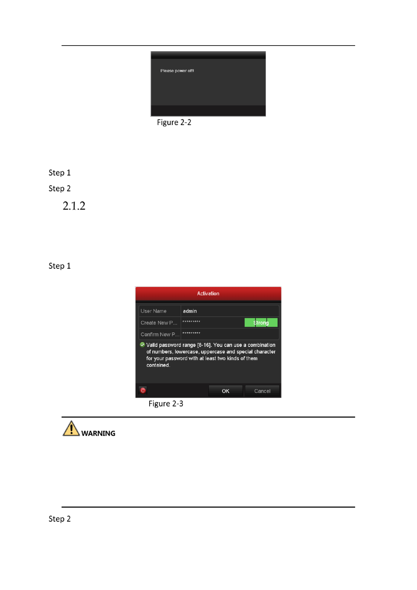
Shutting down the NVR
Go to . Menu > Shutdown
Shutdown Menu
Click shutdown.
Click . Yes
Network Video Recorder User Manual
18
Shutdown Attention
Rebooting the NVR
In the Shutdown menu, you can also reboot the NVR.
Go to . Menu > Shutdown
Click to lock the NVR or to reboot the NVR. Logout Reboot
Activating Your Device
Purpose:
For the first-time access, you need to activate the device by setting an admin
password. No operation is allowed before activation.
Input same password in the text field of and the Create New Password Confirm
New Password.
Settings Admin Password
We highly recommend you create a strong password of your own choosing (Using a
minimum of 8 characters, including at least three of the following categories: upper
case letters, lower case letters, numbers, and special characters.) in order to increase
the security of your product. And we recommend you reset your password regularly,
especially in the high security system, resetting the password monthly or weekly can
better protect your product.
Click to save the password and activate the device. OK

Network Video Recorder User Manual
20
Warning
Using the Unlock Pattern for Login
You can configure the unlock pattern for device login.
Configuring the Unlock Pattern
After the device is activated, you can enter the following interface to configure the
device unlock pattern.
Set Unlock Pattern
Step 1 Use the mouse to draw a pattern among the 9 dots on the screen. Release the
mouse when the pattern is done.

Network Video Recorder User Manual
21
Draw the Pattern
Connect at least 4 dots to draw the pattern.
Each dot can be connected for once only.
Step 2 Draw the same pattern again to confirm it. When the two patterns match, the
pattern is configured successfully.
Confirm the Pattern
If the two patterns are different, you must set the pattern again.

Network Video Recorder User Manual
22
Re-set the Pattern
Logging in via Unlock Pattern
Only the user has the permission to unlock the device. admin
Please configure the pattern first before unlocking. Please refer to Configuring
the Unlock Pattern:
Right click the mouse on the screen and select menu to enter the interface as the
shown in Figure 2.8.
Draw the Unlock Pattern
Draw the pre-defined pattern to unlock to enter the menu operation.
If you have forgotten your pattern, you can select the Forget My Pattern or
Switch User option to enter the normal login dialog box.
When the pattern you draw is different from the pattern you have configured,
you should try again.
If you have drawn the wrong pattern for more than 5 times, the system will
switch to the normal login mode automatically.

Network Video Recorder User Manual
23
Normal Login Dialog Box
Login and Logout
User Log in
Purpose:
If NVR has logged out, you must login the device before operating the menu and
other functions.
Select in the dropdown list. User Name
Login Interface
Input password.
Click to log in. OK
When you forget the password of the admin, you can click Forget Password to reset
the password. Please refer to Chapter 2.1.5 Resetting Your Password for details.
The device gets locked for 60 seconds if the admin user performs 7 failed password
attempts (5 attempts for the guest/operator).
User Logout
Purpose:

Network Video Recorder User Manual
24
After logging out, the monitor turns to the live view mode and if you want to do
some operation, you need to enter user name and password tog in again.
Go to . Menu > Shutdown
Logout
Click . Logout
After you have logged out the system, menu operation on the screen is invalid. It is
required to input a user name and password to unlock the system.
Resetting Your Password
When you forget the password of the admin, you can reset the password by
importing the GUID file. The GUID file must be exported and saved in the local U-
flash disk after you have activated the device (refer to Chapter 2.1.2 Activating Your
Device).
On the user login interface, click to enter the Reset Password Forget Password
interface.
Please insert the U-flash disk stored with the GUID file to the NVR before resetting
password.
Reset Password

Network Video Recorder User Manual
25
Select the GUID file from the U-flash disk and click to import the file to the Import
device.
If you have imported the wrong GUID file for 7 times, you will be not allowed to reset
the password for 30 minutes.
After the GUID file is successfully imported, enter the reset password interface to
set the new admin password.
Click to set the new password. You can export the new GUID file to the U-flash OK
disk for future password resetting.
When the new password is set, the original GUID file will be invalid. The new GUID
file should be exported for future password resetting. You can also enter the
User>User Management interface to edit the admin user and export the GUID file.
Using the Wizard for Basic Configuration
The Setup Wizard can guide you to configure the system resolution, system
date/time, HDD initialization, IP camera management, etc.
If you don’t want to use the setup wizard at that moment, click Exit. You can also
choose to use the Setup Wizard next time by leaving the “Start wizard when the
device starts?” checkbox checked.
Enter the general settings interface to configure the VGA/HDMI resolution,
system date and time, and HDD initialization.
Initialize HDD: check it to initialize the HDD which it is used for the first time.

Network Video Recorder User Manual
26
Start Wizard Interface
Click to enter the IP Camera Management interface. Next
Automatically Add Cameras (for Non-PoE Models)
For non-PoE devices, you can quickly add one or more IP cameras which are
searched within the same network and have the same user name and
password with the device.
Start Wizard Interface

Network Video Recorder User Manual
27
1) Click . Add All
The device starts to automatically search and add the matched cameras.
2) Click when the cameras are added. OK
Manually Add Cameras
1) Click search the online IP cameras within the same network. Search to
2) Click to add the cameras which have the same user name and Add
password with the device.
IP Camera Management
Before adding the camera, make sure the IP camera to be added is in active
status. If the camera is in inactive status, you can click the inactive icon of the camera to
set the password to activate it. You can also select multiple cameras from the list and
click the One-touch Activate to activate the cameras in batch.
Click to complete the startup Setup Wizard. Exit

Network Video Recorder User Manual
28
Adding and Connecting the IP Cameras
Activating the IP Camera
Purpose:
Before adding the camera, make sure the IP camera to be added is in active status.
Select from the right-click menu in live view mode or Go to Add IP Camera Menu>
Camera Camera > to enter the IP camera management interface.
For the IP camera detected online in the same network segment, the Password
status shows whether it is active or inactive.
IP Camera Management Interface
Click the inactive icon of the camera to enter the following interface to activate it.
You can also select multiple cameras from the list and click to One-touch Activate
activate the cameras in batch.
Activate the Camera
Set the password of the camera to activate it.
Use Admin Password: when you check the checkbox, the camera (s) will be
configured with the same admin password of the operating NVR.

Network Video Recorder User Manual
29
Set New Password
Create New Password: If the admin password is not used, you must create the
new password for the camera and confirm it.
We highly recommend you create a strong password of your own choosing (Using a
minimum of 8 characters, including at least three of the following categories: upper
case letters, lower case letters, numbers, and special characters.) in order to increase
the security of your product. And we recommend you reset your password regularly,
especially in the high security system, resetting the password monthly or weekly can
better protect your product.
Click to finish the acitavting of the IP camera. And the security status of OK
camera will be changed to Active.
Adding the Online IP Cameras
Purpose:
The main function of the NVR is to connect the network cameras and record the
video got from it. So before you can get a live view or record of the video, you should
add the network cameras to the connection list of the device.
Before you start:
Ensure the network connection is valid and correct. For detailed checking and
configuring of the network, please see Chapter Checking Network Traffic Chapter and
Configuring Network Detection.
Adding the IP Cameras
OPTION 1:
Select from the right-click menu in live view mode or Go to Add IP Camera Menu>
Camera Camera> to enter the IP camera management interface.

Network Video Recorder User Manual
30
Adding IP Camera Interface
The online cameras with same network segment will be detected and displayed in
the camera list.
Select th IP camera from the list and click the button to add the camera. Or e
you can click to add all cameras (with the same login One-touch Adding
password) from the list.
Make sure the camera to add has already been activated.
(For the encoders with multiple channels only) check the in Channel Port checkbox
the pop-up window, as shown in the following figure, and click to add multiple OK
channels.
Selecting Multiple Channels
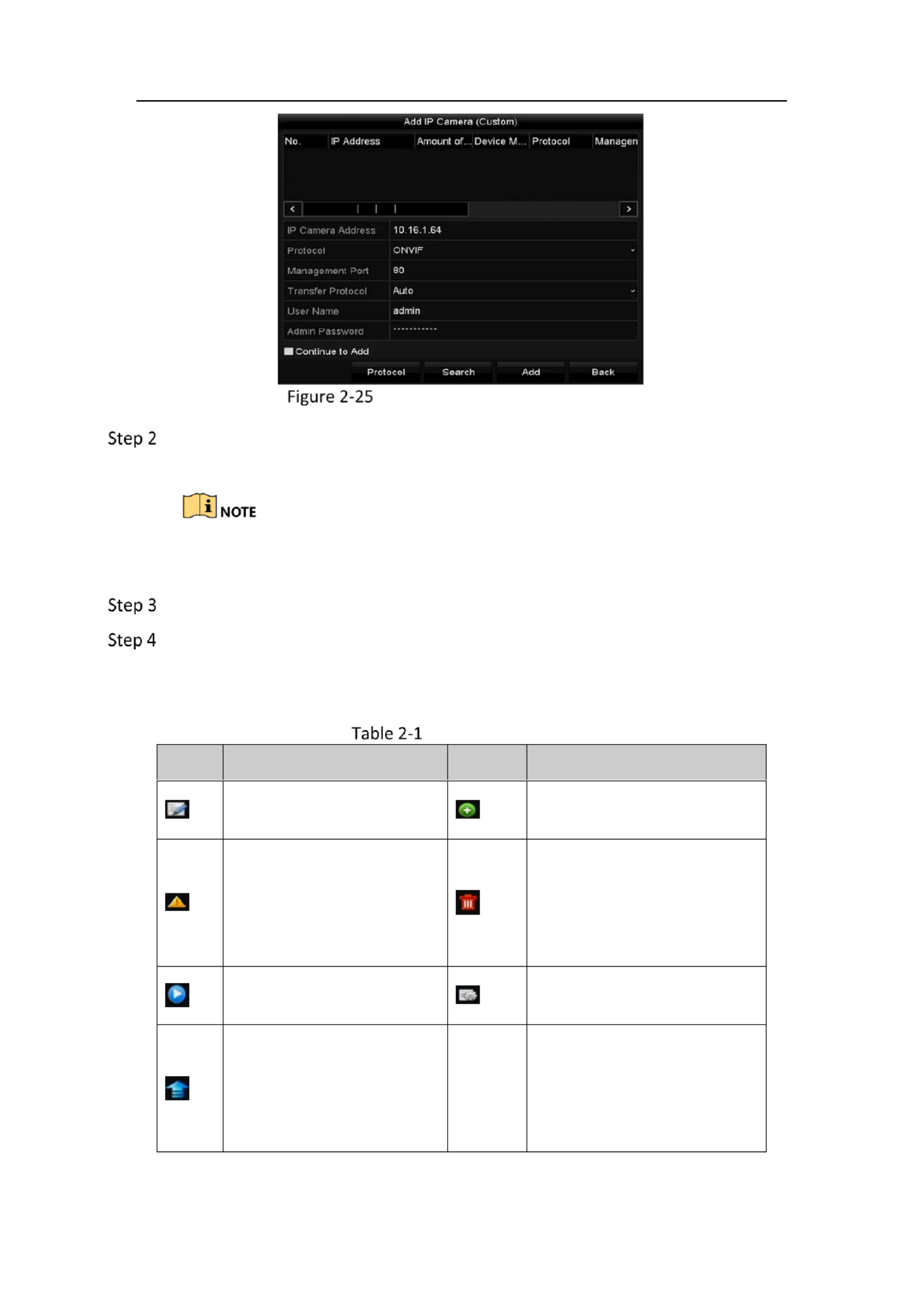
OPTION 2:
On the IP Camera Management interface, click to pop up the Add Custom Adding
IP Camera (Custom) interface.
Network Video Recorder User Manual
31
Custom Adding IP Camera Interface
You can edit the IP address, protocol, management port, and other information of
the IP camera to be added.
If the IP camera to add has not been actiavated, you can activate it from the IP
camera list on the camera management interface.
(Optional) Check to add other IP cameras. Continue to Add
Click to add the camera. The successfully added cameras are listed in the Add
interface.
Refer to the following table for the description of the icons
Description of Icons
Icon
Explanation
Icon
Explanation
Edit basic parameters of
the camera
Add the detected IP camera
The camera is
disconnected; you can click
the icon to get the
exception information of
camera
Delete the IP camera
Play the live video of the
connected camera
Advanced settings of the
camera.
Upgrade the connected IP
camera
Security
Show the security status of
the camera to be
active/inactive or the
password strength
(strong/medium/weak/risk)
Network Video Recorder User Manual
32
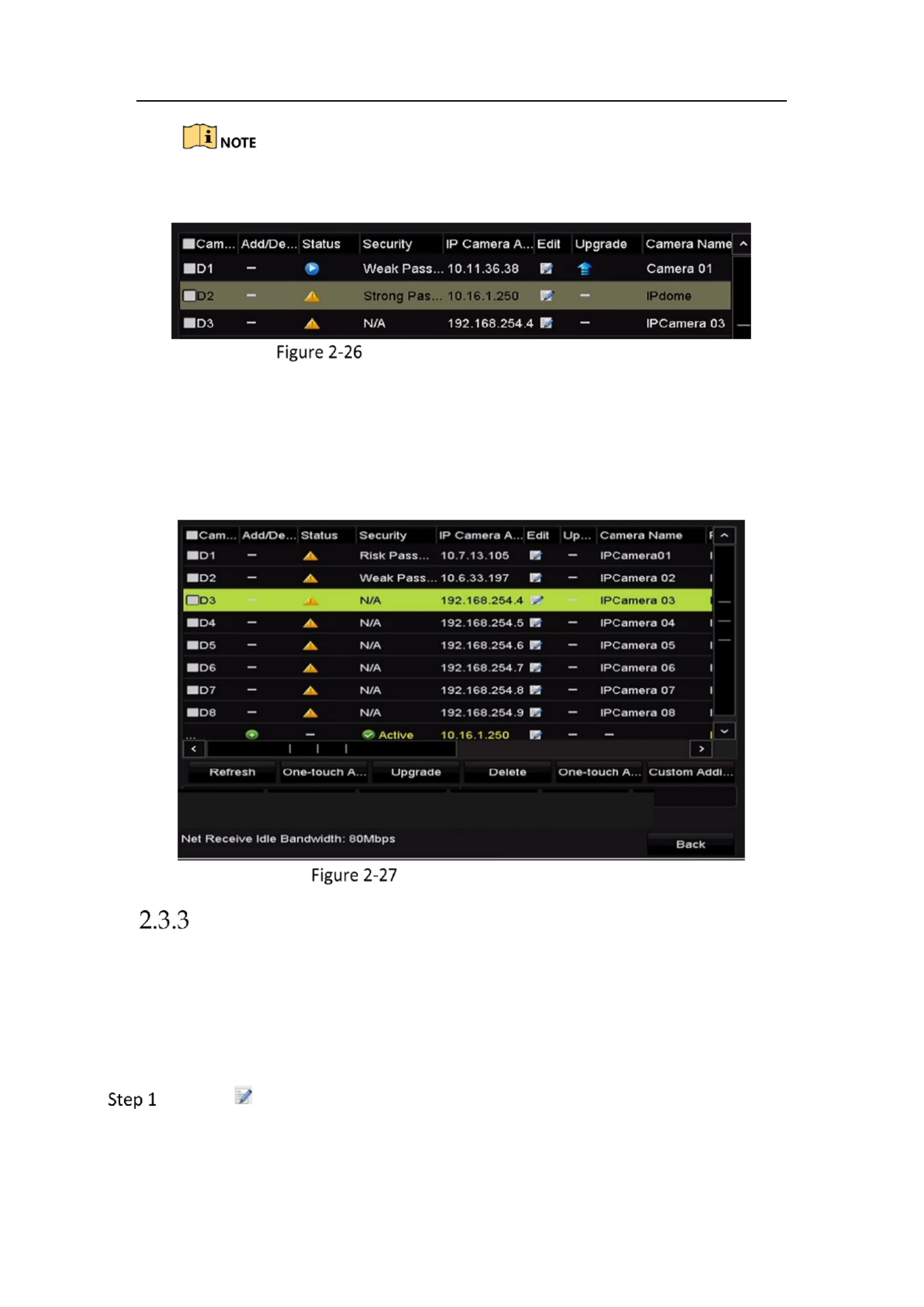
For the added IP cameras, the Security status shows the security level of the
password of camera: strong password, weak password and risk password.
Security Level of IP Camera’s Password
Enabling the Password of IP Camera Visible
For the admin login user account, you can check Show Password of IP Camera to
enable the show the passwords of the successfully added IP cameras in the list.
You must enter the admin password to confirm permission .
Show Password of IP Camera
Editing the Connected IP Cameras and Configuring
Customized Protocols
After the adding of the IP cameras, the basic information of the camera lists in the
page, you can configure the basic setting of the IP cameras.
Editing the IP Camera Parameters
Click the icon to edit the parameters; you can edit the IP address, protocol
and other parameters.

Network Video Recorder User Manual
34
Password Configuration of the Camera
Click to save the settings and exit the interface. OK
Configuring the Customized Protocols
Purpose:
To connect the network cameras which are not configured with the standard
protocols, you can configure the customized protocols for them.
Click in the custom adding IP camera interface to enter the protocol Protocol
management interface.
Protocol Management Interface
There are 16 customized protocols provided in the system, you can edit the
protocol name; and choose whether to enable the sub-stream.
Choose the protocol type of transmission and choose the transfer protocols.

Network Video Recorder User Manual
35
Before customizing the protocol for the network camera, you have to contact the
manufacturer of the network camera to consult the URL (uniform resource locator)
for getting main stream and sub-stream.
The format of the URL is: [Type]://[IP Address of the network camera]:[Port]/[Path].
Example: rtsp://192.168.1.55:554/ch1/main/av_stream.
Protocol Name: Edit the name for the custom protocol.
Enable Substream: If the network camera does not support sub-stream or the
sub-stream is not needed leave the checkbox empty.
Type: The network camera adopting custom protocol must support getting
stream through standard RTSP.
Transfer Protocol: Select the transfer protocol for the custom protocol.
Port: Set the port No. for the custom protocol.
Path: Set the resource path for the custom protocol. E.g., ch1/main/av_stream.
The protocol type and the transfer protocols must be supported by the connected
network camera.
After adding the customized protocols, you can see the protocol name is listed in the
dropdown list of protocol.
Protocol Setting
Choose the protocols you just added to validate the connection of the network
camera.
Editing IP Cameras Connected to the PoE Interfaces
This chapter is only applicable for the /P models.

Network Video Recorder User Manual
36
The PoE interfaces enables the NVR system to pass electrical power safely, along with
data, on Ethernet cabling to the connected network cameras.
Up to 4 network cameras can be connected to models, and network cameras /4P 8 to
/8P models you disable the PoE interface, you can also connect to the online . If
network cameras. And the PoE interface supports the Plug-and-Play function.
To add Cameras for NVR supporting PoE function:
Before you start:
Connect the network cameras via the PoE interfaces.
Go to > . Menu> Camera Camera
List of Connected Cameras
The cameras connecting to the PoE interface cannot be deleted in this menu.
Click the button, and select the Adding Method in the drop-down list.
Plug-and-Play: It means that the camera is connected to the PoE interface,
so in this case, the parameters of the camera can’t be edited. The IP
address of the camera can only be edited in the Network Configuration
interface, see for detailed Chapter .1 Configuring General Settings 11
information.

Network Video Recorder User Manual
37
Edit IP Camera Interface - Plug-and-Play
Manual: You can disable the PoE interface by selecting the manual while
the current channel can be used as a normal channel and the parameters
can also be edited.
Input the IP address, the user name and password of administrator manually,
and click to add the IP camera. OK
Edit IP Camera Interface - Manual

Network Video Recorder User Manual
38
Chapter 3 Live View
Live View displays the video image getting from each camera in real time.
Live View Status Icons
In the live view mode, there are status icons at the upper-right of the screen for each
channel, showing the status of the record and alarm in the channel, so that you can
know whether the channel is recorded, or whether there are alarms occur as soon as
possible.
Description of Live View Icons
Icons
Description
Alarm (video loss, video tampering, motion detection, sensor alarm
or VCA alarm)
Record (manual record, continuous record, motion detection ,
sensor alarm or VCA alarm triggered record)
Alarm & Record
Event/Exception (motion detection, sensor alarm, VCA alarm or
exception information appears at the lower-left corner of the ,
screen. Please refer to Chapter 8.8 Setting Alarm Response
Actions for details.)
Operations in Live View Mode
Right-Click Menu
In live view mode, there are many functions provided. The functions are listed below.
When the aux output is enabled, the main output cannot perform any operation, and
you can do some basic operation on the live view mode for the Aux output.

Network Video Recorder User Manual
39
Mouse Operation in Live View
Name
Description
Common Menu
Quick access to the sub-menus which you frequently visit.
Menu
Enter the main menu of the system by right clicking the
mouse.
Single Screen
Switch to the single full screen by choosing channel number
from the dropdown list.
Multi-screen
Adjust the screen layout by choosing from the dropdown list.
Previous Screen
Switch to the previous screen.
Next Screen
Switch to the next screen.
Start/Stop Auto-
switch
Enable/disable the auto-switch of the screens.
Start Recording
Start continuous recording or motion detection recording of
all channels.
Add IP Camera
Enter the IP Camera Management interface, and manage the
cameras.
Playback
Enter the playback interface and start playing back the video
of the selected channel immediately.
Output Mode
Four modes of output supported, including Standard, Bright,
Gentle and Vivid.
Aux Monitor
The NVR checks the connection of the output interfaces to
define the main and auxiliary output interfaces. The priority
level for the main and aux output is HDMI > VGA
When both the HDMI and VGA are connected, the HDMI is
used as main output and the VGA is used as the aux output .
The of the live view configuration must be set before using dwell time Start Auto-
switch.
The right-click menu varies according to different models, please refer to the actual
GUI menu of the device.
Quick Setting Toolbar in Live View Mode
On the screen of each channel, there is a quick setting toolbar which shows when
you single click the mouse in the corresponding screen.

Network Video Recorder User Manual
41
Image Settings- Customize
Live View Strategy can be selected to set strategy, including Real-time,
Balanced, Fluency.
Live View Strategy
Move the mouse onto the icon to show the real-time stream information,
including the frame rate, bitrate, resolution and stream type.
Information
Adjusting Live View Settings
Purpose:
Live View settings can be customized according to different needs. You can configure
the output interface, dwell time for screen to be shown, mute or turning on the
audio, the screen number for each channel, etc.

Network Video Recorder User Manual
43
1) 36 Select a View mode in . Up to -screen display is
supported for 32-ch NVR.
2) Select the small window, and double-click on the channel number to
display the channel on the window.
3) If you do not want camera to be displayed on the live view interface, the
click the corresponding stop it. to
4) You can also click button to start live view for all the channels and click
to stop all the live view.
5) Click to save the setting.Apply
Set the stream type for live view of camera.
1) Click the to enter the more settings interface. More Settings
2) Select the camera to configure from the list.
3) Select the stream type to Main Stream, S -Stream or Auto. ub
Stream Type Settings
4) Click to save the settings. Apply
5) (Optional) You can click to copy the stream type settings of the current Copy
camera to other camera (s).
Channel-zero Encoding
Purpose:
Sometimes you need to get a remote view of many channels in real time from web
browser or CMS (Client Management System) software, in order to decrease the
bandwidth requirement without affecting the image quality, channel-zero encoding
is supported as an option for you.
Go to > . Menu Configuration > Live View
Select . Channel-Zero Encoding
Live View- Channel-Zero Encoding
Check the checkbox after . Enable Channel Zero Encoding

Network Video Recorder User Manual
47
Setting PTZ Presets, Patrols & Patterns
Before you start:
Please make sure that the presets, patrols and patterns should be supported by PTZ
protocols.
Customizing Presets
Purpose:
Follow the steps to set the Preset location which you want the PTZ camera to point
to when an event takes place.
Go to > > . Menu Camera PTZ
PTZ Settings
Use the directional button to wheel the camera to the location where you want to
set preset; and the zoom and focus operations can be recorded in the preset as
well.
Enter the preset No. (1~255) in the preset text field, and click the button to S et
link the location to the preset.
Repeat the steps2-3 to save more presets.
You can click to clear the location information of the preset, or click Clear the Clear
All button to clear the location information of all the presets.
Calling Presets
Purpose:
This feature enables the camera to point to a specified position such as a window
when an event takes place.
Click the button in the lower-right corner of the PTZ setting interface; PTZ

Network Video Recorder User Manual
48
Or press the PTZ button on the front panel or click the PTZ Control icon in
the quick setting bar, or select the PTZ option in the right-click menu to show the
PTZ control panel.
Choose C in the dropdown list. amera
Click the button to show the general settings of the PTZ control.
PTZ Panel - General
Click to enter the preset No. in the corresponding text field.
Click the button to call it. Call Preset
Customizing Patrols
Purpose:
Patrols can be set to move the PTZ to different key points and have it stay there for a
set duration before moving on to the next key point. The key points are
corresponding to the presets. The presets can be set following the steps above in
Customizing Presets.
Go to > > . Menu Camera PTZ
PTZ Settings

Network Video Recorder User Manual
49
Select patrol No. in the drop-down list of patrol.
Click to add key points for the patrol. Set
Key point Configuration
Configure key point parameters, such as the key point No., duration of staying for
one key point and speed of patrol. The key point is corresponding to the preset.
The determines the order at which the PTZ will follow while cycling Key Point No.
through the patrol. The refers to the time span to stay at the Duration
corresponding key point. The defines the speed at which the PTZ will move Speed
from one key point to the next.
Click to add the next key point to the patrol, and you can click to save the Add OK
key point to the patrol.
You can delete all the key points by clicking for the selected patrol, or Clear
click the button to delete all the key pints for all patrols. Clear All
Calling Patrols
Purpose:
Calling a patrol makes the PTZ to move according the predefined patrol path.
Click the button in the lower-right corner of the PTZ setting interface; PTZ
Or press the PTZ button on the front panel or click the PTZ Control icon in the quick setting bar , or
select the PTZ option in the right-click menu t show the PTZ control panel. o
Click the button to show the general settings of the PTZ control.
PTZ Panel - General
Network Video Recorder User Manual
52
The speed dome starts linear scan from the left limit to the right limit, and you must
set the left limit on the left side of the right limit, as well the angle from the left limit
to the right limit should be no more than .180º
Calling Linear Scan
Before operating this function, make sure the connected camera supports the linear
scan and is in KVISION protocol. HI
Purpose:
Follow the procedure to call the linear scan in the predefined scan range.
Click in the lower-right corner of the PTZ setting interface; PTZ
Or press the PTZ button on the front panel or click the PTZ Control icon in
the quick setting bar to enter the PTZ setting menu in live view mode.
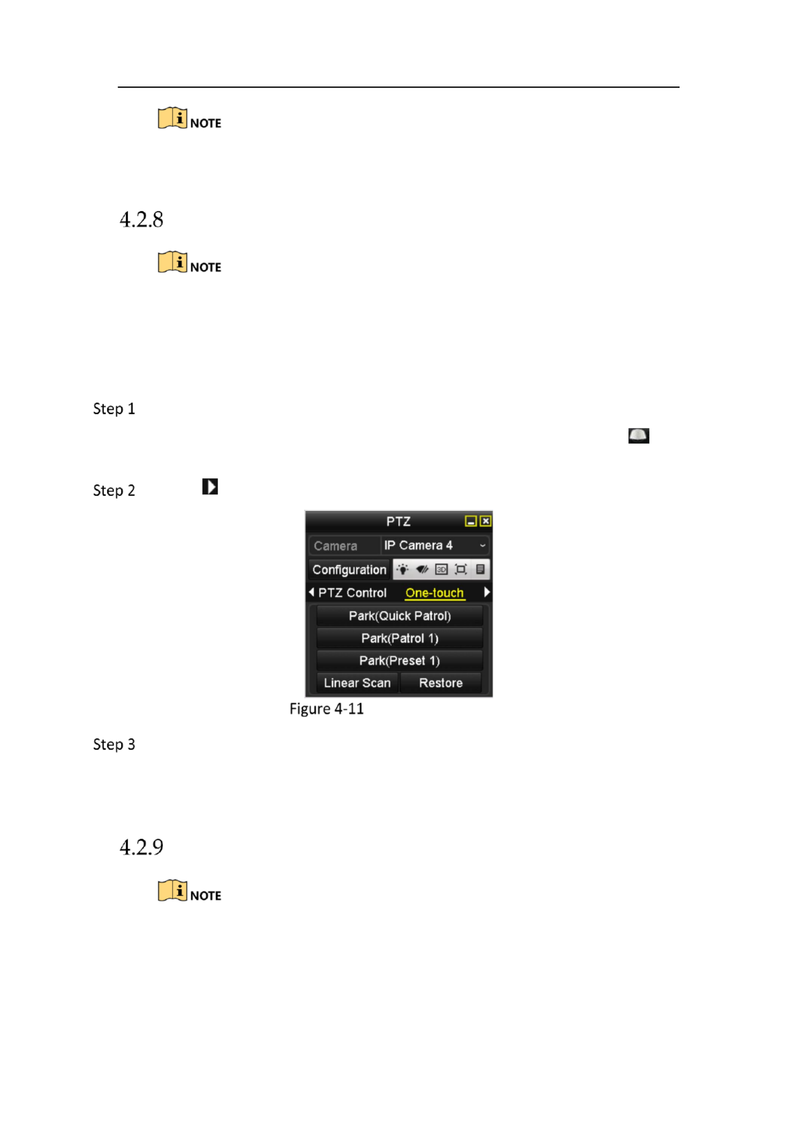
Click the button to show the one-touch function of the PTZ control.
PTZ Panel - One-touch
Click to start the linear scan and click the Linear Scan button again to Linear Scan
stop it.
You can click Restore to clear the defined left limit and right limit data and the
dome needs to reboot to make settings take effect.
One-touch Park
Before operating this function, make sure the connected camera supports the linear
scan and is in HIKVISION protocol.
Purpose:
Produkt Specifikationer
| Mærke: | Hikvision |
| Kategori: | Stemmeoptager |
| Model: | DS-HiWatchI-HWN-2108-8P |
Har du brug for hjælp?
Hvis du har brug for hjælp til Hikvision DS-HiWatchI-HWN-2108-8P stil et spørgsmål nedenfor, og andre brugere vil svare dig
Stemmeoptager Hikvision Manualer

30 December 2025
11 Oktober 2024
10 Oktober 2024
10 Oktober 2024
27 August 2024
20 August 2024
10 August 2024
9 August 2024
7 August 2024
6 August 2024
Stemmeoptager Manualer
- Stemmeoptager Sony
- Stemmeoptager Philips
- Stemmeoptager Grundig
- Stemmeoptager D-Link
- Stemmeoptager Motorola
- Stemmeoptager Roland
- Stemmeoptager Toshiba
- Stemmeoptager Kodak
- Stemmeoptager Yamaha
- Stemmeoptager Olympus
- Stemmeoptager Nedis
- Stemmeoptager Abus
- Stemmeoptager Planet
- Stemmeoptager Aiwa
- Stemmeoptager DataVideo
- Stemmeoptager Trevi
- Stemmeoptager König
- Stemmeoptager Lervia
- Stemmeoptager Olympia
- Stemmeoptager AJA
- Stemmeoptager Tascam
- Stemmeoptager Vivotek
- Stemmeoptager Zoom
- Stemmeoptager Line 6
- Stemmeoptager Saramonic
- Stemmeoptager Samson
- Stemmeoptager RCA
- Stemmeoptager AVerMedia
- Stemmeoptager GoClever
- Stemmeoptager Hanwha
- Stemmeoptager Audioline
- Stemmeoptager Sound Devices
- Stemmeoptager M-Audio
- Stemmeoptager GPO
- Stemmeoptager Provision-ISR
- Stemmeoptager Atomos
- Stemmeoptager Majestic
- Stemmeoptager Audiovox
- Stemmeoptager Axis
- Stemmeoptager Reloop
- Stemmeoptager Sangean
- Stemmeoptager Oregon Scientific
- Stemmeoptager Dahua Technology
- Stemmeoptager Boss
- Stemmeoptager Blackmagic Design
- Stemmeoptager Lectrosonics
- Stemmeoptager Qian
- Stemmeoptager Geovision
- Stemmeoptager Gefen
- Stemmeoptager Airlive
- Stemmeoptager Marquant
- Stemmeoptager Profoon
- Stemmeoptager Mpman
- Stemmeoptager Humax
- Stemmeoptager Engel Axil
- Stemmeoptager EverFocus
- Stemmeoptager Livescribe
- Stemmeoptager Griffin
- Stemmeoptager Kguard
- Stemmeoptager Neo
- Stemmeoptager Epcom
- Stemmeoptager LifeGood
- Stemmeoptager Syscom
- Stemmeoptager Pixel Maker
- Stemmeoptager Feelworld
- Stemmeoptager HiLook
- Stemmeoptager Jammin Pro
Nyeste Stemmeoptager Manualer

15 Januar 2025
14 Januar 2025
29 December 2024

27 December 2024
21 December 2024
15 December 2024

12 December 2024
6 Oktober 2024
30 September 2024
27 September 2024