Honeywell Genesis 7580 Manual
Honeywell
Stregkodelæser
Genesis 7580
Læs nedenfor 📖 manual på dansk for Honeywell Genesis 7580 (68 sider) i kategorien Stregkodelæser. Denne guide var nyttig for 36 personer og blev bedømt med 4.5 stjerner i gennemsnit af 2 brugere
Side 1/68

Genesis™
Presentation Area Imager
7580
User’s Guide

Disclaimer
Honeywell International Inc. (“HII”) reserves the right to make changes in
specifications and other information contained in this document without prior
notice, and the reader should in all cases consult HII to determine whether any
such changes have been made. The information in this publication does not
represent a commitment on the part of HII.
HII shall not be liable for technical or editorial errors or omissions contained
herein: nor for incidental or consequential damages resulting from the furnishing,
performance, or use of this manual.
This document contains propriety information that is protected by copyright.
All rights reserved. No part of this document may be photocopied, reproduced,
or translated into another language without the prior written consent of HII.
© 2010 - 2011 Honeywell International Inc. All rights reserved.
Web Address: www.honeywellaidc.com
Trademarks
Omniplanar, Swiftdecoder, Metrologic, MetroSet2, and TotalFreedom are
trademarks or registered trademarks of Metrologic Instruments, Inc. or Honeywell
International Inc.
Microsoft, Windows 95, and Windows are registered trademarks of Microsoft
Corporation.
IBM is a trademark of International Business Machines Corporation.
Checkpoint is a registered trademark of Checkpoint Systems, Inc.
Other product names mentioned in this manual may be trademarks or
registered trademarks of their respective companies and are the property of their
respective owners.
Patents
For patent information, please refer to www.honeywellaidc.com/patents.

iii
Table of Contents
Introduction
Product Overview ............................................................................................. 1
Base Kit Components ....................................................................................... 2
Optional Accessories ........................................................................................ 2
MS7580 Components ....................................................................................... 4
Labels ............................................................................................................... 5
Maintenance ..................................................................................................... 5
Cable Installation and Removal ........................................................................ 6
Interface Installation
RS232 .............................................................................................................. 7
Keyboard Wedge .............................................................................................. 8
RS485 .............................................................................................................. 9
USB ................................................................................................................ 10
Mounting the MS7580
Components of Adapter Kit 46-00911 ............................................................ 13
Components of Wall Mount Kit 46-00913 ....................................................... 13
Installation of Adapter Kit 46-00911 ............................................................... 14
Installation of Wall Mount Kit 46- 00913 .......................................................... 16
Operation
Modes of Operation ........................................................................................ 17
Audible Indicators ........................................................................................... 19
Visual Indicators ............................................................................................. 20
Failure Modes ................................................................................................. 21
Field of View ................................................................................................... 22
Depth of Field by Minimum Bar Code Element Width .................................... 23
IR Activation Range ........................................................................................ 24
Illumination Source ......................................................................................... 25
IR Source ....................................................................................................... 26
Targeting Source ............................................................................................ 27

iv
Troubleshooting Guide ......................................................................... 29
Design Specifications ........................................................................... 33
Applications and Protocols .................................................................. 35
Configuration and Upgrades ................................................................ 37
Configuration Modes ...................................................................................... 37
Upgrading the Firmware ................................................................................. 37
MS7580 124- -EAS Model
Integrated RF EAS Antenna Connection ........................................................ 39
EAS System Connection ................................................................................ 40
Configuration for EAS Applications ................................................................ 42
EAS Tag Deactivation Range ......................................................................... 44
Imager Pinouts–MS7580 124- -EAS ................................................................ 46
Cable Pinouts ................................................................................................. 47
Antenna Disconnect ....................................................................................... 47
Imager and Cable Terminations
Standard Imager Pinouts ................................................................................ 49
Standard Cable Pinouts.................................................................................. 50
Limited Warranty ................................................................................... 53
Regulatory Compliance
Safety ............................................................................................................. 55
EMC ............................................................................................................... 56
Index ....................................................................................................... 59
Customer Support ................................................................................. 61
Technical Assistance ...................................................................................... 61
Product Service and Repair ............................................................................ 62

1
Introduction
Product Overview
The MS7580 Genesis™ is a high performance presentation -area imaging bar
code imager that utilizes CMOS imaging sensors for superior image quality.
Genesis utilizes custom decoder software, for reliable decoding of both 1D and
2D bar code symbologies. Sharp images can be captured and transmitted in a
variety of outputs including: .jpg, .bmp, and .tiff.
Omnidirectional scanning capabil ities and an excellent motion tolerance provides
aggressive scanning of all standard 1D, GS1 DataBar™ (RSS), PDF417,
microPDF, Composite, Matrix, and Postal Codes symbology types. Firmware
updates are easily loaded into Flash memory.
The MS7580 provides an extended scan volume and a built in object detection
sensor (IR) that instantly turns on the imager when an object is presented within
the imager’s field of view.
Genesis™ Interface Support
MS7580–124
Interfaces supported include:
• RS232
• USB
• Keyboard Wedge
• RS485 (External via Cable)
EAS equipped models are indicated with an EAS extension on the model number
(i.e., MS7580 124 39 47- -EAS). See pages – for additional product information.
-USB is configurable for Keyboard Emulation Mode, Bi Directional Serial Emulation
Mode or IBM OEM. The default USB setting is Keyboard Emulation Mode.
Applicable for IBM® host applications.
Note: Standard models ship with the ability to read all 1D, PDF and 2D bar ,
codes. Decoding and functional capability is limited and imagers will
not support key features including, but not limited to, the ability to
decode PDF, 2D or OCR fonts without proper limited use licenses
provided by Honeywell. If you wish to purchase a limited license for one
or more of the key features not included in the standard , please imager
specify at the time of sale or otherwise contact a customer service
representative for more information.
2
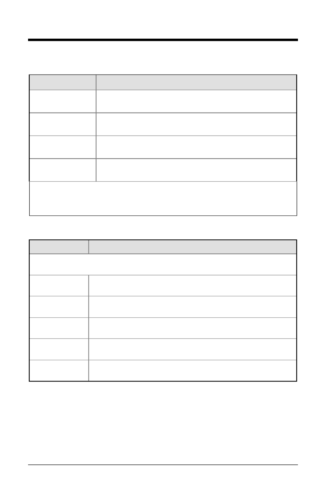
Base Kit Components
Part # Description
MS7580-124 Genesis 7580 Presentation Area Imager
00 02544- MetroSelect® -Single Line Configuration Guide
00-0 2525 Area-Imaging Supplemental Configuration Guide*
GEN- -7580 UG Genesis 7580 Installation and User’s Guide*
EAS equipped models are indicated with an EAS extension on the model number
(i.e., - - – MS7580 124 EAS). See pages 39 47 for additional product information.
.Manuals are available for download from www.honeywellaidc.com
Optional Accessories
Part # Description
AC to DC Power Transformer - 1 Regulated 12VDC @ .25A output.
46 00862- 90VAC to 255VAC United States, Canada and Japan
46 00863 90- VAC to 255VAC Continental European
46 00864- 90VAC to 255VAC United Kingdom
46 00865- 90VAC to 255VAC China
46- 00866 90VAC to 255VAC Australia
Other items may be ordered for the specific protocol being used. To order additional items,
contact the dealer, distributor, cor ustomer service. See page 61 for contact information.

3
Part # Description
Cable Compatibility Warning
The MS7580 requires a cable designed for a 12VDC area imager.
Do not attempt to use any cables other than the specified cables listed below
(cable series 5S 5S- xxx). Any damage incurred from incorrect cable usage
will void the limited warranty shown on page 53.
5S 5S000- -3 RS232 12V VLink Cable with Built in Power Jack
Straight Black Cable with Short Strain Relief
5S 5S002- -3 Keyboard Wedge 12V VLink Cable with Adapter Cable
Straight Black Cable with Short Strain Relief
5S 5S213- -N-3
USB Direct Cable for 12V Host Power
Locking Plus Power™ Type A- Connector
Straight Black Cable with Short Strain Relief
5S 5S235- -3
USB 12V VLink Cable with Built in Power Jack
Non-Locking Type A Connector
Straight Black Cable with Short Strain Relief
MX- - -3 RS485 5S006
RS485 Voltage Converter Cable with Build in Power
Jack
Straight Black Cable with Short Strain Relief
The following MS7580 EAS cables are compatible with Checkpoint- -124
®
System devices. For additional cable information for the MS7580- -EAS, 124
refer pages 39 47– .
MX- -E-3 5S114 RS232 12V VLink Straight, Black Cable
with Built in Power Jack
MX- -E-3 5S236 USB 12V VLink Straight Black Cable with
Built in Power Jack, Non Locking Type A Conne- ctor
46 00911- MS7580 Wall Mount Adapter Kit
46 00913- MS7580 Wall Mount Kit
00 05250- MS7580 Wall Mount Installation Guide
Other items may be ordered for the specific protocol being used. To order additional items,
contact the dealer, distributor, cor ustomer service. See page for contact information.61

4
MS7580 Components
Item Item Description
1 Blue and White LED
See Visual Indicators (on page 20)
2 Button Mode Select Button
3 Speaker See Audible Indicators (on page 19)
4 Window LED Aperture
5 Adjustable Base
6 Cable Connection 10- pin RJ45, Female Socket,
See Imager Pinout Connections ( ) on page 49
7 Cable Release See Cable Installation and Removal (on page 6)
Note: The MS7580 124 model- -EAS is equipped with an integrated antenna
for Electronic Article Surveillance (EAS) system support. See pages
39 47– for additional product information.
Figure Imager Components1.
5
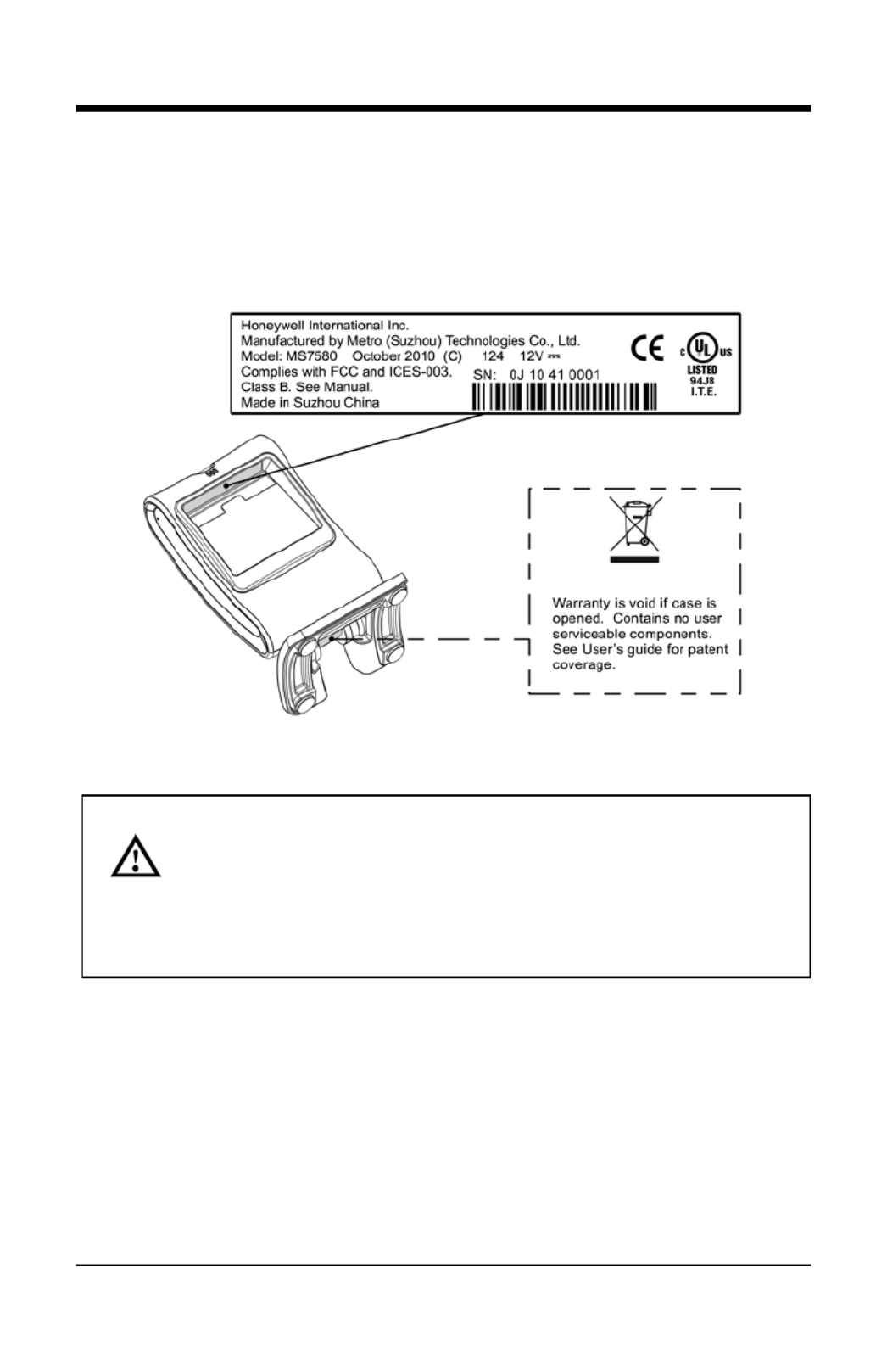
Labels
Each MS7580 has a label located near the top of the output window. This label
provides the imager’s model number, date of manufacture, serial number, CE
and caution information. Additional information has been molded into the
underside of the imager's case. The following figure gives an example of the
label and the molded text with their locations identified.
Figure 2. Label and Molded Text Samples
For North America:
CAUTION: To maintain compliance with applicable standards, all circuits
connected to the must meet the requirements scanner of a NEC Class 2
power source or Limited Power Source as defined in UL 60950 1 Clause 2.5- .
For Other Countries:
CAUTION: To maintain compliance with applicable standards, all circuits
connected to the scanner must meet the requirements of a Limited Power
Source as defined in IEC 60950-1 Clause 2.5.
Maintenance
Smudges and dirt on the imager's window can interfere with the imager's
performance. If the window requires cleaning, use only a mild glass cleaner
containing no ammonia. When cleaning the window, spray the cleaner onto a lint
free, non-abrasive cleaning cloth and then gently wipe the window clean.
If the imager's case requires cleaning, use a mild cleaning agent that does not
contain strong oxidizing chemicals. Strong cleaning agents may discolor or
damage the 's exterior.imager
6
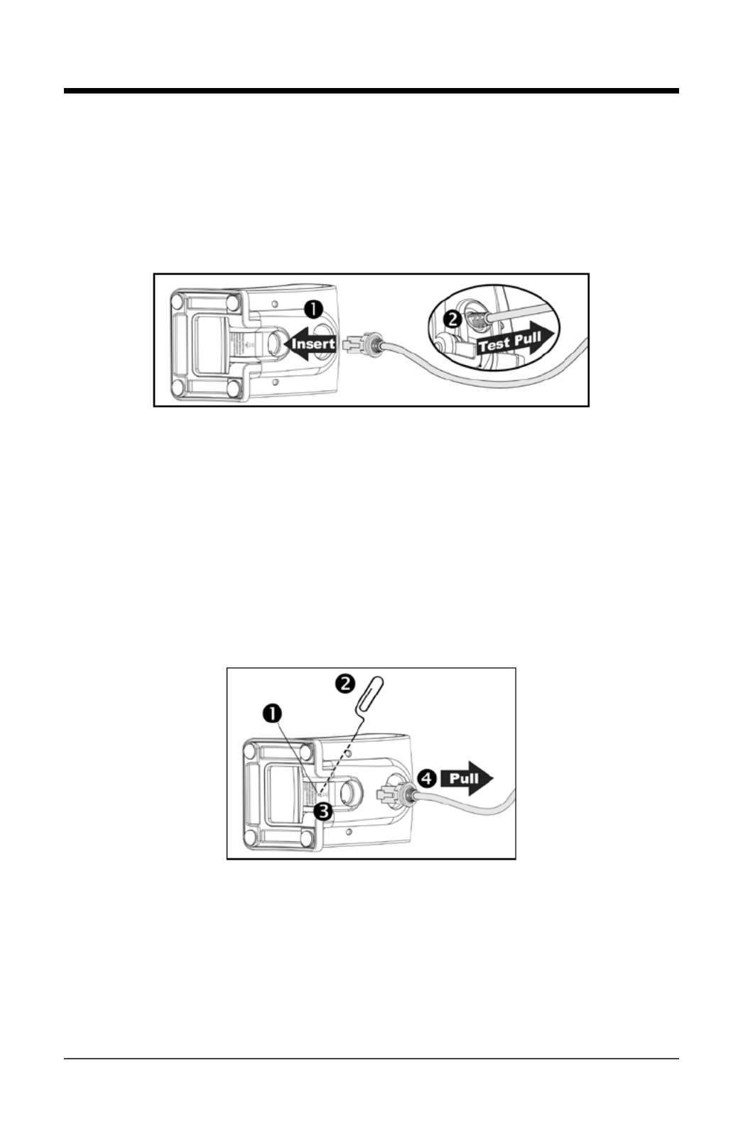
Cable Installation and Removal
Installation
1. Insert the cable’s modular connector into the socket on the imager.
2. ently gPull on the cable strain relief to ensure the cable is installed.
Note: If the cable is not fully latched, the imager may power intermittently.
Figure ble3. Installing the Ca
Removal
Turn the host power off and disconnect the power supply from the cable b efore
attempting to disconnect the cable from the imager.
1. Locate the small pin on the hole imager near the cable connection point.
2. Bend a paperclip into the shape shown below.
3. Insert the paperclip into the pinhole and apply pressure to release the
connector lock.
4. Pull gently on the strain-relief of the cable to remove the cable from the
imager.
Figure Disconnecting4. the Cable
MS7580 124- -EAS Model Note
See page 39 for additional cable installation/removal instructions specific to the
MS7580- -124 EAS Genesis with integrated RF EAS antenna.
7
Interface Installation
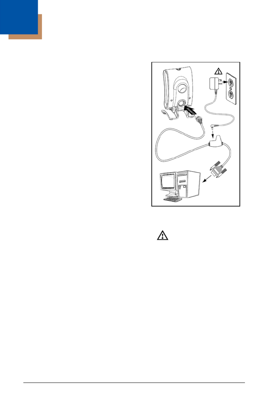
RS232
1. Turn off power to the host device.
2. modular Plug the interface cable’s
connector into the socket on the imager.
3. Connect the other end of the cable to a
dedicated COM port the host device.on
4. Plug the power supply12V into the
power jack on the cable.
5. Check the AC input requirements
of the power supply to the voltage verify
matches the AC outlet. The outlet must
be located near the equipment and
easily accessible.
6. Connect AC power to the transformer.
7. The MS7580 will start to initialize.
The white and blue LED will alternately
fade on and off for three seconds.
When the has finished imager
initializing, the imager will flash the white
LED three times while simultaneously
beep threeing times. The low intensity
blue LED will remain turned on.
8. Turn on power to the host device.
Installation Notes
• - -MS7580 124 EAS models are equipped with an integrated RF EAS
antenna. See page for additional 39 cable installation instructions for
EAS equipped Genesis models.
• Plugging the into a port on the host system does not guarantee imager
that scanned information will be communicated properly to the host
system. The is shipped from the factory configured with default imager
settings. Please refer to the MetroSelect Single Line Configuration -
Guide ( 02544) or MetroSet2’s help files for instructions on PN -00
changing the imager’s configuration. In addition, please check that the
imager and host system are using the same communication protocol.
The MS7580 requires 12V power to function for RS232 operation. Honeywell
recommends using the external power supply shipped with the MS7580.
Figure 5. RS232
See caution on page 5.

8
Keyboard Wedge
1. Turn off power to the host device.
2. modular Plug the interface cable’s
connector imager into the socket on the .
3. Disconnect the keyboard from the
host device.
4. Connect the “Y” ends of the
communication cable to the keyboard
and the keyboard port on the host
device. A male/female adapter cable is
supplied . with the imager kit
5. Plug the power supply12V into the
power jack on the cable.
6. Check the AC input requirements e of th
power supply to verify the voltage
matches the AC outlet. The outlet must
be located near the equipment and be
easily accessible.
7. Connect AC power to the transformer.
8. The MS7580 will start to initialize. The
white and blue LED will alternately fade
on and off for three seconds. When the
imager has finished initializing, the
imager will flash the white LED three
times while simultaneously beeping
three times. The low intensity blue LED
will remain turned on.
9. Turn on power to the host device.
Installation Note
Plugging the into a port on the host system does not guarantee that imager
scanned information will be communicated properly to the host system. The
imager is shipped from the factory configured with default settings. Please refer
to the MetroSelect Single Line Configuration Guide (- PN -00 02544) or
MetroSet2’s help files for instructions on changing the ’s configuration. In imager
addition, please check that the and host system are using the same imager
communication protocol.
The MS7580 requires 12V power to function for Keyboard Wedge operation.
Figure 6. Keyboard Wedge
See caution on page 5.
Produkt Specifikationer
| Mærke: | Honeywell |
| Kategori: | Stregkodelæser |
| Model: | Genesis 7580 |
| Vægt: | 340 g |
| Produktfarve: | Sort |
| Opbevaringstemperatur (T-T): | -40 - 60 °C |
| Relativ luftfugtighed ved drift (H-H): | 0 - 95 % |
| Strømforbrug (standby): | 1.3 W |
| Driftstemperatur (T-T): | 0 - 40 °C |
| Dimensioner (BxDxH): | 83 x 80 x 150 mm |
| Indgangsspænding: | 12 V |
| Standard grænseflader: | USB, RS-232, RS-485 |
| Strømforbrug: | 167 mA |
| Opløsning på optisk sensor: | 832 pixel |
| Strømforbrug (aktiv): | 2 W |
| Pitch læsningsvinkel: | -70 - 70 ° |
| Yaw læsningsvinkel: | -75 - 75 ° |
| Afkodningsstandarder: | 1D, 2D, PDF, OCR |
Har du brug for hjælp?
Hvis du har brug for hjælp til Honeywell Genesis 7580 stil et spørgsmål nedenfor, og andre brugere vil svare dig
Stregkodelæser Honeywell Manualer

29 December 2024
29 December 2024
3 Oktober 2024
13 September 2024
28 August 2024
28 August 2024
28 August 2024
21 August 2024
20 August 2024
18 August 2024
Stregkodelæser Manualer
- Stregkodelæser Nilox
- Stregkodelæser IFM
- Stregkodelæser Motorola
- Stregkodelæser Nedis
- Stregkodelæser Casio
- Stregkodelæser Palm
- Stregkodelæser Trimble
- Stregkodelæser König
- Stregkodelæser Deltaco
- Stregkodelæser Digitus
- Stregkodelæser Zebra
- Stregkodelæser Olympia
- Stregkodelæser ELO
- Stregkodelæser Intermec
- Stregkodelæser Datalogic
- Stregkodelæser Newland
- Stregkodelæser Renkforce
- Stregkodelæser Manhattan
- Stregkodelæser DeLOCK
- Stregkodelæser Opticon
- Stregkodelæser Qian
- Stregkodelæser Godex
- Stregkodelæser Steren
- Stregkodelæser Argox
- Stregkodelæser IC Intracom
- Stregkodelæser Adesso
- Stregkodelæser POSline
- Stregkodelæser Metapace
- Stregkodelæser Wasp
- Stregkodelæser Approx
- Stregkodelæser Brady
- Stregkodelæser Baracoda
- Stregkodelæser Posiflex
- Stregkodelæser Datamax-O'neil
- Stregkodelæser CipherLab
- Stregkodelæser Cypress
- Stregkodelæser DENSO
- Stregkodelæser Socket Mobile
- Stregkodelæser Mach Power
- Stregkodelæser QUIO
- Stregkodelæser EC Line
- Stregkodelæser Tecno
- Stregkodelæser ZBA
- Stregkodelæser Code Corporation
- Stregkodelæser Hamlet
- Stregkodelæser Qoltec
- Stregkodelæser Vultech
- Stregkodelæser Psion
- Stregkodelæser Koamtac
- Stregkodelæser Unitech
- Stregkodelæser Atlantis Land
- Stregkodelæser ID-Tech
- Stregkodelæser Code
- Stregkodelæser Bluebird
- Stregkodelæser Cognex
Nyeste Stregkodelæser Manualer

24 Marts 2025
24 Marts 2025
26 Februar 2025
23 Februar 2025
23 Februar 2025
23 Februar 2025
23 Februar 2025
23 Februar 2025
21 Februar 2025
20 Februar 2025