Lenovo Ideacentre AIO 520-24ARR Manual
Lenovo
Skrivebord
Ideacentre AIO 520-24ARR
Læs nedenfor 📖 manual på dansk for Lenovo Ideacentre AIO 520-24ARR (107 sider) i kategorien Skrivebord. Denne guide var nyttig for 12 personer og blev bedømt med 4.5 stjerner i gennemsnit af 2 brugere
Side 1/107

ideacentreAll-In-One520(22&24inch)
ComputerHardwareMaintenanceManual
MachineTypes:F0D1[AIO520-24IKL/EnergyStar]F0D2[AIO
520-24IKU/EnergyStar]/F0D3[AIO520-24AST/EnergyStar]F0D4
[AIO520-22IKL/EnergyStar]/F0D5[AIO520-22IKU/EnergyStar]
F0D6[AIO520-22AST/EnergyStar]


ideacentreAll-In-One520(22&24inch)
Computer
HardwareMaintenanceManual
MachineTypes:F0D1[AIO520-24IKL/EnergyStar]F0D2[AIO
520-24IKU/EnergyStar]/F0D3[AIO520-24AST/EnergyStar]F0D4
[AIO520-22IKL/EnergyStar]/F0D5[AIO520-22IKU/EnergyStar]
F0D6[AIO520-22AST/EnergyStar]

FirstEdition(July2017)
©CopyrightLenovo2017.
LIMITEDANDRESTRICTEDRIGHTSNOTICE:IfdataorsoftwarearedeliveredpursuantaGeneralServices
Administration“GSA”contract,use,reproduction,ordisclosureissubjecttorestrictionssetforthinContractNo.
GS-35F-05925

Contents
Chapter1.Aboutthismanual......1
ImportantSafetyInformation..........1
Chapter2.Safetyinformation......3
Generalsafety................3
Electricalsafety...............3
Safetyinspectionguide............5
Handlingelectrostaticdischarge-sensitive
devices..................5
Groundingrequirements............6
Safetynotices................6
Chapter3.Generalinformation.....9
Specifications................9
Chapter4.GeneralCheckout.....11
Chapter5.UsingtheSetupUtility...13
StartingtheLenovoBIOSSetupUtilityprogram.13
Viewingandchangingsettings........13
Usingpasswords..............13
Enablingordisablingadevice........15
Selectingastartupdevice..........16
ExitingtheLenovoBIOSSetupUtilityprogram..17
Chapter6.Symptom-to-FRUIndex..19
Harddiskdrivebooterror..........19
PowerSupplyProblems...........19
POSTerrorcodes.............20
Undeterminedproblems...........20
Chapter7.Locatingconnectors,
controlsandcomponents......21
Chapter8.Replacinghardware....31
Generalinformation.............31
Replacingthekeyboardandmouse......32
Replacingtheadapter............32
Removingthestandbase..........33
Removingtherearcover...........33
Replacingthecamera............37
Replacingtheheat-sink...........38
ReplacingtheCPU.............39
Replacingtheharddiskdrive.........42
Replacingthesystemfan..........43
Replacingtheopticaldrive..........44
Replacingthememorymodule........45
Replacingthesolidstatedrive........47
ReplacingtheWi-Ficard...........47
ReplacingthesideUSBboard........48
Replacingthemotherboard..........49
Removingthestandholder..........51
ReplacingtheMicrophonemodule.......51
Replacingthespeakersystem........52
ReplacingtheLCDpanelmodule.......53
Chapter9.FRUlists..........57
Chapter10.Generalinformation..101
AdditionalServiceInformation........101
©CopyrightLenovo2017 iii

ivideacentreAll-In-One520(22&24inch)ComputerHardwareMaintenanceManual
Chapter1.Aboutthismanual
ThismanualcontainsserviceandreferenceinformationforLenovoAll-In-One520seriescomputerslistedon
thecover.ItisintendedonlyfortrainedservicerswhoarefamiliarwithLenovocomputerproducts.
BeforeservicingaLenovoproduct,besuretoreadtheSafetyInformation.
ThedescriptionoftheTV-tunercardinthismanualappliesonlytocomputerswithaTV-tunercardinstalled.
ItdoesnotapplytocomputerswithoutaTV-tunercard.
ImportantSafetyInformation
BesuretoreadallCAUTIONandDANGERsectionsinthismanualbeforefollowinganyoftheinstructions.
VeuillezliretouteslesconsignesdetypeDANGERetATTENTIONduprésentdocumentavantd’exécuter
lesinstructions.
LesenSieunbedingtalleHinweisevomT yp“ACHTUNG”oder“VORSICHT”indieserDokumentation,bevor
SieirgendwelcheVorgängedurchführen
LeggereleistruzioniintrodottedaATTENZIONEePERICOLOpresentinelmanualeprimadieseguireuna
qualsiasidelleistruzioni
Certifique-sedelertodasasinstruçõesdecuidadoeperigonestemanualantesdeexecutarqualquer
umadasinstruções
Esimportantequeleatodaslasdeclaracionesdeprecauciónydepeligrodeestemanualantesdeseguir
lasinstrucciones.
©CopyrightLenovo2017 1

2ideacentreAll-In-One520(22&24inch)ComputerHardwareMaintenanceManual

Chapter2.Safetyinformation
Thischaptercontainsthesafetyinformationthatyouneedtobefamiliarwithbeforeservicingacomputer.
Generalsafety
Followtheserulestoensuregeneralsafety:
•Keeptheareasaroundthecomputerclearandcleanduringandaftermaintenance.
•Whenliftinganyheavyobject:
1.Ensureyoucanstandsafelywithoutslipping.
2.Distributetheweightoftheobjectequallyacrossbothfeet.
3.Liftslowly.Nevermovesuddenlyortwistwhenyouattempttolift.
4.Liftbystandingorbypushingupwithyourlegmuscles;thisactionremovesthestrainfromthe
musclesinyourback.
Donotattempttoliftanyobjectsthatweighmorethan16kg(35lb)orobjectsthatyouthinkare
tooheavyforyou.
•Donotperformanyactionthatwouldcreateahazardforthecustomer,orwouldmakethecomputer
unsafe.
•Beforeyoustartthecomputer,ensurethatotherservicerepresentativesandcustomerpersonnelarenot
inapositionthatwouldcreateahazardforthem.
•Placeremovedcoversandotherpartsinasafeplace,awayfromallpersonnel,whileyouareservicingthe
computer.
•Keepyourtoolcaseawayfromareasthatpeoplemaywalkthroughtoensureno-onetripsoverit.
•Donotwearlooseclothingthatcanbetrappedinthemovingpartsofamachine.Ensurethatyoursleeves
arefastenedorrolledupaboveyourelbows.Ifyourhairislong,tieorfastenitback.
•Inserttheendsofyournecktieorscarfinsideclothingorfastenitwithanon-conductiveclip,
approximately8centimeters(3inches)fromtheend.
•Donotwearjewelry,chains,metal-frameeyeglasses,ormetalfastenersforyourclothing.
Remember:Metalobjectsaregoodelectricalconductors.
•Wearsafetyglasseswhenyouare:hammering,drillingsoldering,cuttingwire,attachingsprings,using
solvents,orworkinginanyotherconditionsthatmightbehazardoustoyoureyes.
•Afterservice,reinstallallsafetyshields,guards,labels,andgroundwires.Replaceanysafetydevice
thatiswornordefective.
•Reattachallcoverscorrectlybeforereturningthecomputertothecustomer.
Electricalsafety
CAUTION:
Electricalcurrentfrompower,telephone,andcommunicationcablescanbehazardous.T oavoid
personalinjuryorequipmentdamage,disconnectanyattachedpowercords,telecommunication
cables,networkcables,andmodemcablesbeforeyouopenthecomputercovers,unlessinstructed
otherwiseintheinstallationandconfigurationprocedures.
©CopyrightLenovo2017 3

Observethefollowingruleswhenworkingonelectricalequipment.
Important:Useonlyapprovedtoolsandtestequipment.Somehandtoolshavehandlescoveredwithasoft
materialthatdoesnotinsulateyouwhenworkingwithliveelectricalcurrents.Manycustomershaverubber
floormatsneartheirequipmentthatcontainsmallconductivefiberstodecreaseelectrostaticdischarge.
•Findtheroomemergencypower-off(EPO)switch,disconnectingswitch,orelectricaloutlet.Ifanelectrical
accidentoccurs,youcanthenoperatetheswitchorunplugthepowercordquickly.
•Donotworkaloneunderhazardousconditionsornearequipmentthathashazardousvoltages.
•Disconnectallpowerbefore:
–Performingamechanicalinspection
–Workingnearpowersupplies
–RemovingorinstallingFieldReplaceableUnits(FRUs)
•Beforeyoustarttoworkonthecomputer,unplugthepowercord.Ifyoucannotunplugit,askthe
customertopower-offtheelectricaloutletthatsuppliespowertothemachineandtolocktheelectrical
outletintheoffposition.
•Ifyouneedtoworkonacomputerthathasexposedelectricalcircuits,observethefollowingprecautions:
–Ensurethatanotherperson,familiarwiththepower-offcontrols,isnearyou.
Remember:Anotherpersonmustbetheretoswitchoffthepower,ifnecessary.
–Useonlyonehandwhenworkingwithpowered-onelectricalequipment;keeptheotherhandinyour
pocketorbehindyourback.
Remember:Theremustbeacompletecircuittocauseelectricalshock.Byobservingtheaboverule,
youmaypreventacurrentfrompassingthroughyourbody.
–Whenusingatester,setthecontrolscorrectlyandusetheapprovedprobeleadsandaccessoriesfor
thattester.
–Standonsuitablerubbermats(obtainedlocally,ifnecessary)toinsulateyoufromgroundssuchas
metalfloorstripsandmachineframes.
Observethespecialsafetyprecautionswhenyouworkwithveryhighvoltages;theseinstructionsarein
thesafetysectionsofthemaintenanceinformation.Useextremecarewhenmeasuringhighvoltages.
•Regularlyinspectandmaintainyourelectricalhandtoolstoensuretheyaresafetouse.
•Donotusewornorbrokentoolsandtesters.
•Neverassumethatpowerhasbeendisconnectedfromacircuit.First,checkthatithasbeenpoweredoff.
•Alwayslookcarefullyforpossiblehazardsinyourworkarea.Examplesofthesehazardsarewetfloors,
non-groundedpowerextensioncables,conditionsthatmaycauseorallowpowersurges,andmissing
safetygrounds.
•Donottouchliveelectricalcircuitswiththereflectivesurfaceofaplasticdentalmirror.Thissurfaceis
conductive,andtouchingalivecircuitcancausepersonalinjuryanddamagetothecomputer.
•Donotservicethefollowingpartswiththepoweronwhentheyareremovedfromtheirnormaloperating
positionsinacomputer:
–Powersupplyunits
–Pumps
–Blowersandfans
–Motorgenerators
andsimilarunits.(Thispracticeensurescorrectgroundingoftheunits.)
•Ifanelectricalaccidentoccurs:
–Usecaution;donotbecomeavictimyourself.
4ideacentreAll-In-One520(22&24inch)ComputerHardwareMaintenanceManual

–Switchoffpower.
–Sendanotherpersontogetmedicalaid.
Safetyinspectionguide
Theintentofthisinspectionguideistoassistyouinidentifyingpotentialhazardsposedbytheseproducts.
Eachcomputer,asitwasdesignedandbuilt,hadrequiredsafetyitemsinstalledtoprotectusersand
servicepersonnelfrominjury.Thisguideaddressesonlythoseitems.However,goodjudgmentshouldbe
usedtoidentifypotentialsafetyhazardsduetoattachmentoffeaturesoroptionsnotcoveredbythis
inspectionguide.
Ifanyhazardsarepresent,youmustdeterminehowserioustheapparenthazardcouldbeandwhetheryou
cancontinuewithoutfirstresolvingtheproblem.
Considerthefollowingitemsandthesafetyhazardstheypresent:
•Electricalhazards,especiallyprimarypower(primaryvoltageontheframecancauseseriousorfatal
electricalshock).
•Explosivehazards,suchasadamagedCRTfaceorbulgingcapacitor
•Mechanicalhazards,suchaslooseormissinghardware
Theguideconsistsofaseriesofstepspresentedasachecklist.Beginthecheckswiththepoweroff,and
thepowercorddisconnected.
Checklist:
1.Checkexteriorcoversfordamage(loose,broken,orsharpedges).
2.Power-offthecomputer.Disconnectthepowercord.
3.Checkthepowercordfor:
a.Athird-wiregroundconnectoringoodcondition.Useametertomeasurethird-wireground
continuityfor0.1ohmorlessbetweentheexternalgroundpinandframeground.
b.Thepowercordshouldbetheappropriatetypeasspecifiedinthepartslistings.
c.Insulationmustnotbefrayedorworn.
4.Removethecover.
5.Checkforanyobviousalterations.Usegoodjudgmentastothesafetyofanyalterations.
6.Checkinsidetheunitforanyobvioushazards,suchasmetalfilings,contamination,waterorother
liquids,orsignsoffireorsmokedamage.
7.Checkforworn,frayed,orpinchedcables.
8.Checkthatthepower-supplycoverfasteners(screwsorrivets)havenotbeenremovedortamperedwith.
Handlingelectrostaticdischarge-sensitivedevices
Anycomputerpartcontainingtransistorsorintegratedcircuits(ICs)shouldbeconsideredsensitiveto
electrostaticdischarge(ESD).ESDdamagecanoccurwhenthereisadifferenceinchargebetweenobjects.
ProtectagainstESDdamagebyequalizingthechargesothatthecomputer,thepart,theworkmat,andthe
personhandlingthepartareallatthesamecharge.
Notes:
1.Useproduct-specificESDprocedureswhentheyexceedtherequirementsnotedhere.
2.MakesurethattheESDprotectivedevicesyouusehavebeencertified(ISO9000)asfullyeffective.
WhenhandlingESD-sensitiveparts:
Chapter2.Safetyinformation5

•Keepthepartsinprotectivepackagesuntiltheyareinsertedintotheproduct.
•Avoidcontactwithotherpeoplewhilehandlingthepart.
•Wearagroundedwriststrapagainstyourskintoeliminatestaticonyourbody.
•Preventthepartfromtouchingyourclothing.Mostclothingisinsulativeandretainsachargeeven
whenyouarewearingawriststrap.
•Usetheblacksideofagroundedworkmattoprovideastatic-freeworksurface.Thematisespecially
usefulwhenhandlingESD-sensitivedevices.
•Selectagroundingsystem,suchasthoselistedbelow,toprovideprotectionthatmeetsthespecific
servicerequirement.
Note:TheuseofagroundingsystemisdesirablebutnotrequiredtoprotectagainstESDdamage.
–AttachtheESDgroundcliptoanyframeground,groundbraid,orgreen-wireground.
–UseanESDcommongroundorreferencepointwhenworkingonadouble-insulatedor
battery-operatedsystem.Youcanusecoaxorconnector-outsideshellsonthesesystems.
–Usetheroundground-prongoftheACplugonAC-operatedcomputers.
Groundingrequirements
Electricalgroundingofthecomputerisrequiredforoperatorsafetyandcorrectsystemfunction.Proper
groundingoftheelectricaloutletcanbeverifiedbyacertifiedelectrician.
Safetynotices
TheCAUTIONandDANGERsafetynoticesinthissectionareprovidedinthelanguageofEnglish.
DANGER
Electricalcurrentfrompower,telephoneandcommunicationcablesishazardous.
Toavoidashockhazard:
•Donotconnectordisconnectanycablesorperforminstallation,maintenance,orreconfiguration
ofthisproductduringanelectricalstorm.
•Connectallpowercordstoaproperlywiredandgroundedelectricaloutlet.
•Connectanyequipmentthatwillbeattachedtothisproducttoaproperlywiredoutlet.
•Whenpossible,useonehandonlytoconnectordisconnectsignalcables.
•Neverturnonanyequipmentwhenthereisevidenceoffire,water,orstructuraldamage.
•Disconnecttheattachedpowercords,telecommunicationscables,networkcables,andmodem
cablesbeforeyouopenthedevicecovers,unlessinstructedotherwiseintheinstallationand
configurationprocedures.
•Connectanddisconnectcablesasdescribedinthefollowingtablewheninstalling,moving,or
openingcoversonthisproductorattacheddevices.
6ideacentreAll-In-One520(22&24inch)ComputerHardwareMaintenanceManual

ToConnect ToDisconnect
1.T urneverythingOFF .
2.First,attachallcablestodevices.
3.Attachsignalcablestoconnectors.
4.Attachpowercordstooutlet.
5.T urndeviceON.
1.T urneverythingOFF .
2.First,removepowercordsfromoutlets.
3.Removesignalcablesfromconnectors.
4.Removeallcablesfromdevices.
CAUTION:
Whenreplacingthelithiumbattery,useonlyPartNumber45C1566oranequivalenttypebattery
recommendedbythemanufacturer.Ifyoursystemhasamodulecontainingalithiumbattery,replace
itonlywiththesamemoduletypemadebythesamemanufacturer.Thebatterycontainslithiumand
canexplodeifnotproperlyused,handled,ordisposedof.
Donot:
•Throwintoorimmerseinwater
•Heattomorethan100°C(212°F)
•Repairordisassemble
Disposeofthebatteryasrequiredbylocalordinancesorregulations.
CAUTION:
Whenlaserproducts(suchasCD-ROMs,DVD-ROMdrives,fiberopticdevices,ortransmitters)are
installed,notethefollowing:
•Donotremovethecovers.Removingthecoversofthelaserproductcouldresultinexposureto
hazardouslaserradiation.Therearenoserviceablepartsinsidethedevice.
•Useofcontrolsoradjustmentsorperformanceofproceduresotherthanthosespecifiedherein
mightresultinhazardousradiationexposure.
DANGER
SomelaserproductscontainanembeddedClass3AorClass3Blaserdiode.Notethefollowing:
Thesediodesemitradiationwhenopen.Donotstareintothebeam,donotviewdirectlywith
opticalinstruments,andavoiddirectexposuretothebeam.
Chapter2.Safetyinformation7
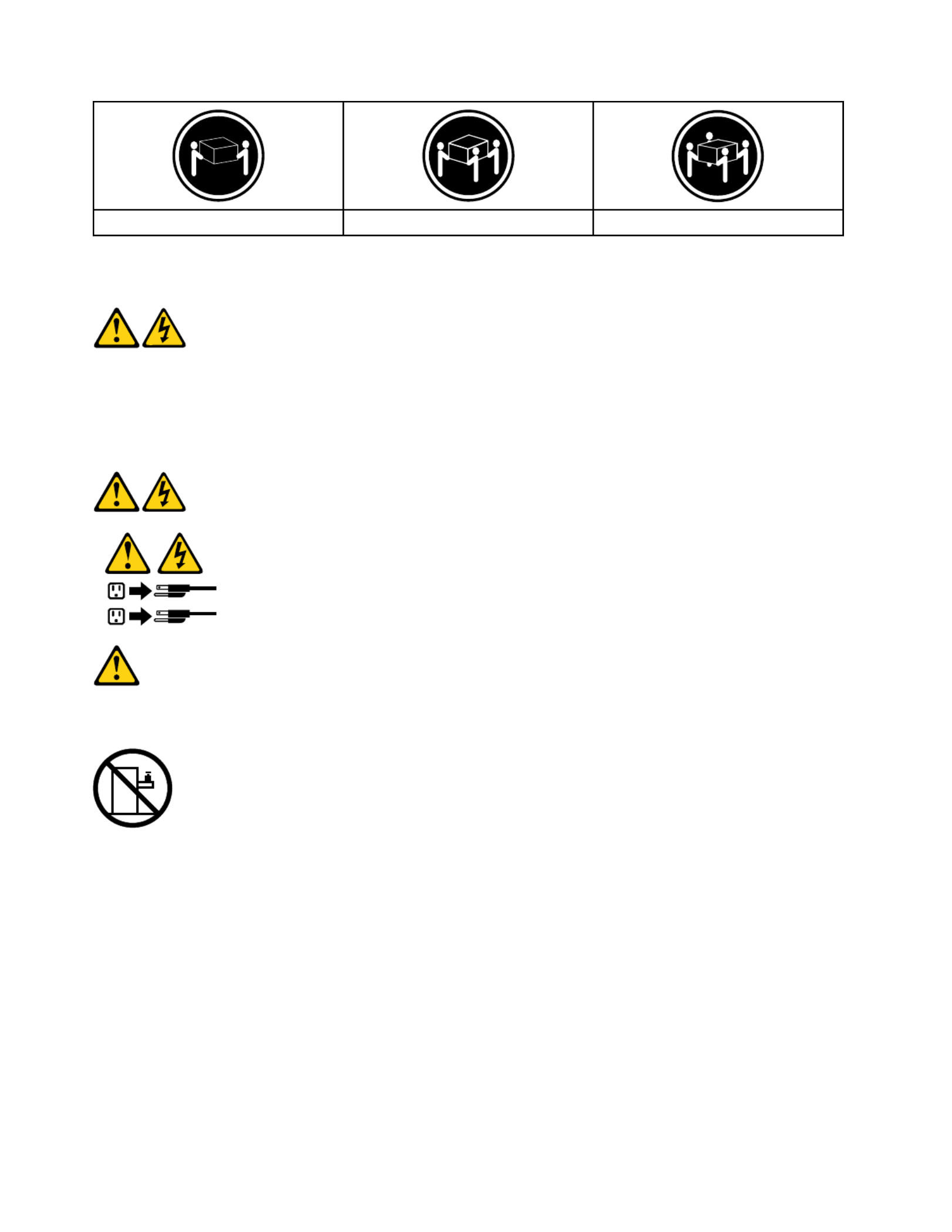
≥18kg(37lbs)≥32kg(70.5lbs)≥55kg(121.2lbs)
CAUTION:
Usesafepracticeswhenlifting.
CAUTION:
Thepowercontrolbuttononthedeviceandthepowerswitchonthepowersupplydonotturnoff
theelectricalcurrentsuppliedtothedevice.Thedevicealsomighthavemorethanonepower
cord.Toremoveallelectricalcurrentfromthedevice,ensurethatallpowercordsaredisconnected
fromthepowersource.
1
2
CAUTION:
Donotplaceanyobjectweighingmorethan82kg(180lbs.)ontopofrack-mounteddevices.
8ideacentreAll-In-One520(22&24inch)ComputerHardwareMaintenanceManual

Chapter3.Generalinformation
Thischapterprovidesgeneralinformationthatappliestoallcomputermodelscoveredbythismanual.
Specifications
Thissectionliststhephysicalspecificationsforyourcomputer.
Thissectionliststhephysicalspecificationsforyourcomputer.
TypeLenovoAll-In-One520
Thissectionliststhephysicalspecifications.
Environment
Airtemperature:
Operating:10°to35°C
Transit:-20°to55°C
Humidity:
Operating:35%to80%
Transit:20%to90%(40°C)
Altitude:86KPato106KPa
Electricalinput:
Inputvoltage:90V-264V(AC)
Inputfrequency:47Hz-63Hz
©CopyrightLenovo2017 9

10ideacentreAll-In-One520(22&24inch)ComputerHardwareMaintenanceManual

Chapter4.GeneralCheckout
Attention:Thedrivesinthecomputeryouareservicingmighthavebeenrearrangedorthedrivestartup
sequencemayhavebeenchanged.Beextremelycarefulduringwriteoperationssuchascopying,saving,or
formatting.Dataorprogramscanbeoverwrittenifyouselectanincorrectdrive.
Generalerrormessagesappearifaproblemorconflictisfoundbyanapplication,theoperatingsystem,or
both.Foranexplanationofthesemessages,refertotheinformationsuppliedwiththatsoftwarepackage.
Usethefollowingproceduretohelpdeterminethecauseoftheproblem:
1.Power-offthecomputerandallexternaldevices.
2.Checkallcablesandpowercords.
3.Setalldisplaycontrolstothemiddleposition.
4.Power-onallexternaldevices.
5.Power-onthecomputer.
•Lookfordisplayederrorcodes.
•Lookforreadableinstructionsoramainmenuonthedisplay.
Ifyoudidnotreceivethecorrectresponse,proceedtostep6.
Ifyoudidreceivethecorrectresponse,proceedtostep7.
6.Ifoneofthefollowinghappens,followtheinstructiongiven:
•IfthecomputerdisplaysaPOSTerror,goto“POSTerrorcodes” .
•Ifthecomputerhangsandnoerrorisdisplayed,continueatstep7.
7.Iftheteststopsandyoucannotcontinue,replacethelastdevicetested.
©CopyrightLenovo2017 11

12ideacentreAll-In-One520(22&24inch)ComputerHardwareMaintenanceManual

Chapter5.UsingtheSetupUtility
TheSetupUtilityprogramisusedtoviewandchangetheconfigurationsettingsofyourcomputer,regardless
ofwhichoperatingsystemyouareusing.However,theoperatingsystemsettingsmightoverrideanysimilar
settingsintheSetupUtilityprogram.
StartingtheLenovoBIOSSetupUtilityprogram
TostarttheLenovoBIOSSetupUtilityprogram,dothefollowing:
1.Ifyourcomputerisalreadyonwhenyoustartthisprocedure,shutdowntheoperatingsystemand
turnoffthecomputer.
2.PressandholdtheF1keythenturnonthecomputer.WhentheLenovoBIOSSetupUtilityprogramis
displayed,releasetheF1key.
Note:IfaPower-OnPasswordoranAdministratorPasswordhasbeenset,theSetupUtilityprogrammenu
willnotbedisplayeduntilyoutypeyourpassword.Formoreinformation,see“Usingpasswords.”
Viewingandchangingsettings
SystemconfigurationoptionsarelistedintheLenovoBIOSSetupUtilityprogrammenu.T ovieworchange
settings,see“StartingtheSetupUtilityprogram.”
YoumustusethekeyboardwhenusingtheLenovoBIOSSetupUtilitymenu.Thekeysusedtoperform
varioustasksaredisplayedonthebottomofeachscreen.
Usingpasswords
YoucanusetheLenovoBIOSSetupUtilityprogramtosetpasswordstopreventunauthorizedpersons
fromgainingaccesstoyourcomputeranddata.See“StartingtheSetupUtilityprogram.”Thefollowing
typesofpasswordsareavailable:
•AdministratorPassword
•Power-OnPassword
Youdonothavetosetanypasswordstouseyourcomputer.However,ifyoudecidetosetpasswords,read
thefollowingsections.
Passwordconsiderations
Apasswordcanbeanycombinationoflettersandnumbersupto16characters(a-zand0-9).Forsecurity
reasons,itisagoodideatouseastrongpasswordthatcannotbeeasilycompromised.Wesuggestthat
passwordsshouldfollowtheserules:
•Forastrongpassword,use7-16charactersandamixoflettersandnumbers.
•Donotuseyournameoryourusername.
•Donotuseacommonwordoracommonname.
•Usesomethingsignificantlydifferentfromyourpreviouspassword.
Attention:AdministratorandPower-Onpasswordsarenotcasesensitive.
©CopyrightLenovo2017 13

AdministratorPassword
SettinganAdministratorPassworddetersunauthorizedpersonsfromchangingconfigurationsettings.Y ou
mightwanttosetanAdministratorPasswordifyouareresponsibleformaintainingthesettingsofseveral
computers.
AfteryousetanAdministratorPassword,apasswordpromptisdisplayedeverytimeyouaccesstheLenovo
BIOSSetupUtilityprogram.
IfboththeAdministratorandPower-OnPasswordareset,youcantypeeitherpassword.However,youmust
useyourAdministratorPasswordtochangeanyconfigurationsettings.
Setting,changing,ordeletinganAdministratorpassword
T osetanAdministratorPassword,dothefollowing:
Note:Apasswordcanbeanycombinationoflettersandnumbersupto16characters(a-zand0-9).For
moreinformation,see“Passwordconsiderations”onpage13.
1.StarttheLenovoBIOSSetupUtilityprogram(see“StartingtheLenovoBIOSSetupUtilityprogram”on
page13).
2.FromtheSecuritymenu,selectSetAdministratorPasswordandpresstheEnterkey.
3.Thepassworddialogboxwillbedisplayed.T ypethepasswordthenpresstheEnterkey.
4.Re-typethepasswordtoconfirm,thenpresstheEnterkey.Ifyoutypedthepasswordcorrectly,
thepasswordwillbeinstalled.
T ochangeanAdministratorPassword,dothefollowing:
1.StarttheLenovoBIOSSetupUtilityprogram(see“StartingtheLenovoBIOSSetupUtilityprogram”on
page13).
2.FromtheSecuritymenu,selectSetAdministratorPasswordandpresstheEnterkey.
3.Thepassworddialogboxwillbedisplayed.T ypethecurrentpasswordthenpresstheEnterkey.
4.T ypethenewpassword,thenpresstheEnterkey.Re-typethepasswordtoconfirmthenewpassword.
Ifyoutypedthenewpasswordcorrectly,thenewpasswordwillbeinstalled.ASetupNoticedconfirming
thatchangeshavebeensavedwillbedisplayed.
T odeleteapreviouslysetAdministratorPassword,dothefollowing:
1.FromtheSecuritymenu,selectSetAdministratorPasswordandpresstheEnterkey.
2.Thepassworddialogboxwillbedisplayed.T ypethecurrentpasswordandpresstheEnterkey.
3.T odeleteanAdministratorPassword,leaveeachnewpasswordlineitemblank,thenpresstheEnter
key.ASetupNoticeconfirmingthatchangeshavebeensavedwillbedisplayed.
4.ReturntotheLenovoBIOSSetupUtilityprogrammenuandselecttheExitoption.
5.SelectSavechangesandExitfromthemenu.
Power-OnPassword
WhenaPower-OnPasswordisset,youcannotstarttheLenovoBIOSSetupUtilityprogramuntilavalid
passwordistypedfromthekeyboard.
Setting,changing,ordeletingaPower-OnPassword
Note:Apasswordcanbeanycombinationoflettersandnumbersupto16characters(a-zand0-9).
14ideacentreAll-In-One520(22&24inch)ComputerHardwareMaintenanceManual

TosetaPower-OnPassword,dothefollowing:
1.StarttheLenovoBIOSSetupUtilityprogram(See”StartingtheLenovoBIOSSetupUtilityprogram”on
page13.)
2.FromtheSecuritymenu,selectSetPower-OnPasswordandpresstheEnterkey.
3.Thepassworddialogboxwillbedisplayed.Typethepassword,thenpresstheEnterkey.
4.Re-typethepasswordtoconfirm.Ifyoutypedthepasswordcorrectly,thepasswordwillbeinstalled.
TochangeaPower-OnPassword,dothefollowing:
1.StarttheLenovoBIOSSetupUtilityprogram(See”StartingtheLenovoBIOSSetupUtilityprogram”on
page13.)
2.FromtheSecuritymenu,selectSetPower-OnPasswordandpresstheEnterkey.
3.Thepassworddialogboxwillbedisplayed.TypethecurrentpasswordthenpresstheEnterkey.
4.T ypethenewpassword,thenpresstheEnterkey.Re-typethepasswordtoconfirmthenewpassword.
Ifyoutypedthenewpasswordcorrectly,thenewpasswordwillbeinstalled.ASetupNoticedconfirming
thatchangeshavebeensavedwillbedisplayed.
TodeleteapreviouslysetPower-OnPassword,dothefollowing:
1.FromtheSecuritymenu,selectSetPower-OnPasswordandpresstheEnterkey.
2.Thepassworddialogboxwillbedisplayed.TypethecurrentpasswordandpresstheEnterkey.
3.T odeletethePower-OnPassword,leaveeachnewpasswordlineitemblank,thenpressEnter.ASetup
Noticeconfirmingthatchangeshavebeensavedwillbedisplayed.
4.ReturntotheLenovoBIOSSetupUtilityprogrammenuandselecttheExitoption.
5.SelectSavechangesandExitfromthemenu.
Enablingordisablingadevice
TheDevicesoptionsisusedtoenableordisableuseraccesstothefollowingdevices:
USBFunctionshertoenableordisableUSB(UniversalSerial
Bus)functions.Ifthefunctionsaredisabled,noUSB
devicescanbeused.
SATAMode WhenthisfeatureissettoDisabled,alldevices
connectedtotheSATAconnectors(e.g.harddiskdrives
ortheopticaldiskdrive)aredisabledandcannotbe
accessed.
OnboardAudioControllerSelectwhethertoenableordisabletheOnboard
AudioController.WhenthisfeatureissettoDisabled
alldevicesconnectedtotheaudioconnectors(e.g.
headphonesoramicrophone)aredisabledandcannot
beused.
OnboardEthernetControllerorLANBootAgentSelectwhethertoenableordisabletheOnboardEthernet
Controller,orselectwhethertoenableordisableload
onboardPXE(PrebootExecutionEnvironment).
Toenableordisableadevice,dothefollowing:
1.StarttheSetupUtilityprogram(see“StartingtheSetupUtilityprogram”onpage13).
2.FromtheSetupUtilityprogrammenu,selectDevices.
3.Selectanoptionasfollows:
SelectUSBSetup,presstheEnterkey,thenselectUSBFunctions.
Chapter5.UsingtheSetupUtility15

SelectATADeviceSetup,presstheEnterkey,thenselectSATAMode.
SelectAudioSetup,presstheEnterkey,thenselectOnboardAudioController.
SelectNetworkSetup,presstheEnterkey,thenselectOnboardEthernetSupportorLANBoot
Agent.
4.SelectDisabledorEnabledandpresstheEnterkey.
5.ReturntotheLenovoBIOSSetupUtilityprogrammenuandselecttheExitoption.
6.SelectSavechangesandExitfromthemenu.
Notes:
a.Ifyoudonotwanttosavethesettings,selectDiscardchangesandExitfromthemenu.
b.SelectIDE/AHCIMode:DevicedriversupportisrequiredforACHI.Dependingonhowtheharddisk
imagewasinstalled,changingthissettingmaypreventthesystemfrombooting.
Selectingastartupdevice
IfyourcomputerdoesnotbootfromadevicesuchastheCD/DVD-ROMdrivediskorharddiskasexpected,
followoneoftheproceduresbelow.
Selectingatemporarystartupdevice
Usethisproceduretostartupfromanybootdevice.
Note:NotallCDs,DVDsorharddiskdrivesarebootable.
1.T urnoffyourcomputer.
2.PressandholdtheF12keythenturnonthecomputer.WhentheStartupDeviceMenuappears,
releasetheF12key.
Note:IftheStartupDeviceMenudoesnotdisplayusingthesesteps,repeatedlypressandreleasethe
F12keyratherthankeepingitpressedwhenturningonthecomputer.
3.Use↑and↓arrowstoselectthedesiredstartupdevicefromtheStartupDeviceMenuandpress
theEnterkeytobegin.
Note:SelectingastartupdevicefromtheStartupDeviceMenudoesnotpermanentlychangethe
startupsequence.
Selectingorchangingthestartupdevicesequence
Tovieworpermanentlychangetheconfiguredstartupdevicesequence,dothefollowing:
1.StarttheLenovoBIOSSetupUtilityprogram(see“StartingtheLenovoBIOSSetupUtilityprogram”on
page13).
2.FromtheLenovoBIOSSetupUtilityprogrammainmenu,selecttheStartupoption.
3.PresstheEnterkey,andselectthedevicesforthePrimaryBootSequence.Readtheinformation
displayedontherightsideofthescreen.
4.Use-and¯arrowstoselectadevice.Usethe<+>or<->keystomoveadeviceupordown.Usethe
<×>keytoexcludethedevicefromorincludethedeviceinthebootsequence.
5.ReturntotheLenovoBIOSSetupUtilityprogrammenuandselecttheExitoption.
6.SelectSavechangesandExitfromthemenu.
Notes:
16ideacentreAll-In-One520(22&24inch)ComputerHardwareMaintenanceManual

a.Ifyoudonotwanttosavethesettings,selectDiscardchangesandExitfromthemenu.
b.Ifyouhavechangedthesesettingsandwanttoreturntothedefaultsettings,selectLoadOptimal
Defaultsfromthemenu.
ExitingtheLenovoBIOSSetupUtilityprogram
Afteryoufinishviewingorchangingsettings,presstheEsckeytoreturntotheLenovoBIOSSetupUtility
programmainmenu.YoumighthavetopresstheEsckeyseveraltimes.Dooneofthefollowing:
•Ifyouwanttosavethenewsettings,selectSavechangesandExitfromthemenu.WhentheSave&
resetwindowshows,selecttheYesbutton,andthenpresstheEnterkeytoexittheLenovoBIOS
SetupUtilityprogram.
•Ifyoudonotwanttosavethesettings,selectDiscardchangesandExitfromthemenu.Whenthe
ResetWithoutSavingwindowshows,selecttheYesbutton,andthenpresstheEnterkeytoexitthe
LenovoBIOSSetupUtilityprogram.
Chapter5.UsingtheSetupUtility17

18ideacentreAll-In-One520(22&24inch)ComputerHardwareMaintenanceManual

Chapter6.Symptom-to-FRUIndex
TheSymptom-to-FRUindexlistserrorsymptomsandpossiblecauses.Themostlikelycauseislistedfirst.
AlwaysbeginwithChapter4,“GeneralCheckout,”onpage11.Thisindexcanalsobeusedtohelpyou
decidewhichFRUstohaveavailablewhenservicingacomputer.Ifyouareunabletocorrecttheproblem
usingthisindex,goto“Undeterminedproblems”onpage20.
Notes:
•Ifyouhavebothanerrormessageandanincorrectaudioresponse,diagnosetheerrormessagefirst.
•Ifyoucannotrunthediagnostictestsoryougetadiagnosticerrorcodewhenrunningatestbutdid
receiveaPOSTerrormessage,diagnosethePOSTerrormessagefirst.
•Ifyoudidnotreceiveanyerrormessagelookforadescriptionofyourerrorsymptomsinthefirstpartof
thisindex.
Harddiskdrivebooterror
Aharddiskdrivebooterrorcanbecausedbythefollowing.
Error FRU/Action
Thestartupdriveisnotincludedinthebootsequence
configuration.
Checktheconfigurationandensurethestartupdriveis
inthebootsequence.
Nooperatingsystemisinstalledonthebootdrive.Installanoperatingsystemonthebootdrive.
Thebootsectoronthestartupdriveiscorrupted. Thedrivemustbeformatted.Dothefollowing:
1.Attempttobackupthedataonthefailingharddisk
drive.
2.Usetheoperatingsystemtoformattheharddisk
drive.
Thedriveisdefective. Replacetheharddiskdrive.
PowerSupplyProblems
Followtheseproceduresifyoususpectthereisapowersupplyproblem.
Check/Verify
Checkthatthefollowingareproperlyinstalled:
•PowerCord
•On/OffSwitchconnector
•SystemBoardPowerSupplyconnectors
•Microprocessorconnections
Reseatconnectors
Checkthepowercord.PowerCord
Checkthepower-onswitch.Power-onSwitch
©CopyrightLenovo2017 19

POSTerrorcodes
Eachtimeyouturnthecomputeron,itperformsaseriesofteststocheckthatthesystemisoperating
correctlyandthatcertainoptionsareset.ThisseriesoftestsiscalledthePower-OnSelf-Test,orPOST.
POSTdoesthefollowing:
•Checkssomebasicmotherboardoperations
•Checksthatthememoryisworkingcorrectly
•Startsvideooperations
•Verifiesthatthebootdriveisworking
POSTErrorMessageescription/Action
Keyboarderror Cannotinitializethekeyboard.Makesurethekeyboard
isproperlyconnectedtothecomputerandthatnokeys
areheldpressedduringPOST .T opurposelyconfigure
thecomputerwithoutakeyboard,selectKeyboardless
operationinStartupandsettheoptiontoEnabled.The
BIOSthenignoresthemissingkeyboardduringPOST .
RebootandSelectproperBootdeviceorInsertBoot
MediainselectedBootdevice
TheBIOSwasunabletofindasuitablebootdevice.Make
surethebootdriveisproperlyconnectedtothecomputer.
Makesureyouhavebootablemediainthebootdevice.
Undeterminedproblems
1.Power-offthecomputer.
2.Removeordisconnectthefollowingcomponents(ifconnectedorinstalled)oneatatime.
a.Externaldevices(modem,printer,ormouse)
b.Extendedvideomemory
c.ExternalCache
d.ExternalCacheRAM
e.Harddiskdrive
f.Diskdrive
3.Power-onthecomputertore-testthesystem.
4.Repeatsteps1through3untilyoufindthefailingdeviceorcomponent.
Ifalldevicesandcomponentshavebeenremovedandtheproblemcontinues,replacethesystemboard.
20ideacentreAll-In-One520(22&24inch)ComputerHardwareMaintenanceManual
Chapter7.Locatingconnectors,controlsandcomponents
Thissectionprovidesillustrationstohelplocatethevariousconnectors,controlsandcomponentsofthe
computer.
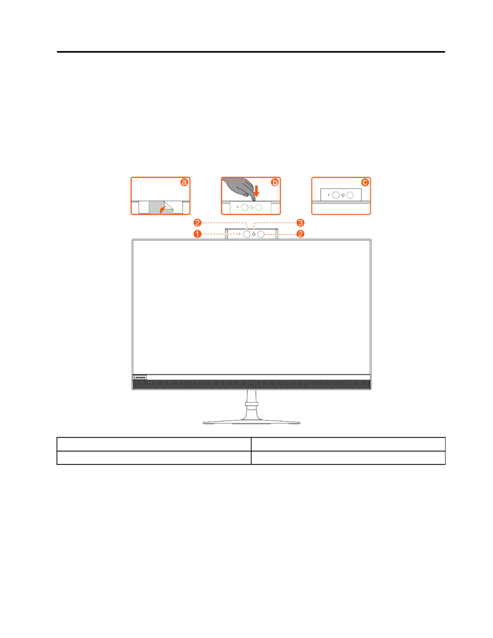
Fontview
Thefollowingillustrationshowsthelocationofcontrolsandcomponentsonthefrontofthecomputer.
Attention:Becarefulnottoblockanyairventsonthecomputer.Blockedairventscancauseoverheating.
1.CameraLEDindicator 3.Built-incamera
2.InfraredLEDs(Selectedmodelsonly)
©CopyrightLenovo2017 21

Leftandrightview
Thefollowingillustrationshowsthelocationofconnectors,controlsandcomponentsontheleftandright
sideofthecomputer.
1.USB3.0connectors 3.Powerbutton
2.Opticaldrive(Optional)4.Cableclip
22ideacentreAll-In-One520(22&24inch)ComputerHardwareMaintenanceManual

Rearview
Thefollowingillustrationshowsthelocationofconnectorsandcomponentsontherearofthecomputer.
1.SecuritycableslotSB2.0connector
2.Powerconnector 7.USB2.0connector
3.Ethernetconnector 8.USB2.0connector
4.HDMI-outconnector 9.HDMI-inconnector(Optional)
5.USB2.0connector 10.Airvent
Chapter7.Locatingconnectors,controlsandcomponents23

Hardwarecomponents
Thefollowingillustrationshowsthecomponentsthatmakeupyourcomputer.
Nonetouchmodel
1.Standholder 221.Powercord
2.Standbase
3.Rearcover 24.Hingecover(bottom)
4.HDDshielding 25.Cameramodule
5.HDDbracket 26.Motherboardframe
6.Harddiskdrive 27.Systemfan
7.HDDcable
8.ODDcable 29.Motherboard
9.ODDbezel
24ideacentreAll-In-One520(22&24inch)ComputerHardwareMaintenanceManual

10.Opticaldiskdrive 31.Battery
11.ODDbracketwithlatchassembly 32.Memorycard
12.ODDboard 33.Wi-Ficover
132.LVDscable
14.LCDMainframeD
15.LCDpanel 36.RFAntennacables
16.LCDbacklightcable37.Cardreadercable
17.Powerswitchboard 38.USBandAudiocable
18.MicrophoneModule(withbracket)39.SideI/Oshielding
19.SpeakersystemdeI/OUSBboard
20.Frontdeco
21.Poweradapterboard
Chapter7.Locatingconnectors,controlsandcomponents25

T ouchmodel
1.Standholder)
2.Standbasem)
3.Rearcover 24.Cameramodule
4.HDDshielding 25.Motherboardframe
5.HDDbracket 26.Systemfan
6.Harddiskdrive
7.HDDcable
8.ODDcable
9.ODDbezel 30.Battery
10.Opticaldiskdrive 31.Memorycard
11.ODDbracketwithlatchassembly 32.Wi-Ficover
26ideacentreAll-In-One520(22&24inch)ComputerHardwareMaintenanceManual

12.ODDboard 33.Wi-Ficard
13.LVDscable 34.SSD
14.LCDpanelmodule 35.RFAntennacables
15.LCDbacklightcable36.Cardreadercable
16.Powerswitchboard 37.USBandAudiocable
17.MicrophoneModule(withbracket)38.SideI/Oshielding
18.SpeakersystemdeI/OUSBboard
19.Frontdeco
20.Poweradapterboard
21.Powercord
Chapter7.Locatingconnectors,controlsandcomponents27

Identifyingpartsonthemotherboard
Themotherboard(sometimescalledtheplanarorsystemboard)isthemaincircuitboardinyourcomputer.
Itprovidesbasiccomputingfunctionsandsupportsavarietyofdevicesthatarefactory-installedorthat
youcaninstalllater.Thefollowingillustrationshowsthelocationofconnectorsandcomponentsonthe
frontofthemotherboard.
AIO520–24AST/AIO520–22AST
1.Battery
2.HDDSAT Aconnecto 14.Wificonnector
3.HDDpowerconnector 15.Speakerconnector
4.DC-INconnectorardconnector
5.Ethernetconnector 17.I/Oboardconnector
6.HDMI-outconnector 18.SSDSATAconnector
7.USB2.0connectoronverterconnector
8.USB2.0connector 20.Powerswitchboardconnector
9.USB2.0connector 21.4-in-1connector
10.USB3.0connector2.Systemfanconnector
11.HDMI-inconnector 23.ODDboardconnector
12.Cameraconnector
28ideacentreAll-In-One520(22&24inch)ComputerHardwareMaintenanceManual

AIO520–24IKU/AIO520–22IKU
1.Battery
2.HDDSAT Aconnecto 14.Wificonnector
3.HDDpowerconnector 15.Speakerconnector
4.DC-INconnectorOboardconnector
5.Ethernetconnector 17.I/Oboardconnector
6.HDMI-outconnector 18.SSDSAT Aconnector
7.USB2.0connector9.Converterconnector
8.USB2.0connector 20.Powerswitchboardconnector
9.USB2.0connector 21.4-in-1connector
10.USB3.0connector22.Systemfanconnector
11.HDMI-inconnector 23.ODDboardconnector
12.Cameraconnector
AIO520–24IKL/AIO520–22IKL
Chapter7.Locatingconnectors,controlsandcomponents29

1.Battery
2.HDDSAT Aconnecto 14.Wificonnector
3.HDDpowerconnector 15.Speakerconnector
4.DC-INconnectorardconnector
5.Ethernetconnector 17.I/Oboardconnector
6.HDMI-outconnector 18.SSDSAT Aconnector
7.USB2.0connectoronverterconnector
8.USB2.0connector 20.Powerswitchboardconnector
9.USB2.0connector 21.4-in-1connector
10.USB3.0connector2.Systemfanconnector
11.HDMI-inconnector 23.ODDboardconnector
12.Cameraconnector
30ideacentreAll-In-One520(22&24inch)ComputerHardwareMaintenanceManual

Chapter8.Replacinghardware
Attention:Donotremovethecomputercoverorattemptanyrepairbeforereadingthe“Importantsafetyinformation”
intheSafetyandWarrantyGuidethatwasincludedwithyourcomputer.T oobtaincopiesoftheSafetyandWarranty
Guide,gototheSupportWebsiteat:http://consumersupport.lenovo.com.
Note:UseonlypartsprovidedbyLenovo.
Generalinformation
Pre-disassemblyinstructions
Beforestartingthedisassemblyprocedure,makesurethatyoudothefollowing:
1.Turnoffthepowertothesystemandallperipherals.
2.Unplugallpowerandsignalcablesfromthecomputer.
3.Placethesystemonaflat,stablesurface.
©CopyrightLenovo2017 31

Replacingthekeyboardandmouse
Note:YourkeyboardwillbeconnectedtoaUSBconnectorateithersideorattherearofthecomputer.
Toreplacethekeyboardandmouse:
Step1.Removeanymediafromthedrives,shutdownthecomputer,andturnoffallattacheddevices.
Step2.Unplugallpowercordsfromelectricaloutlets.
Step3.Disconnectallcablesattachedtothecomputer.Thisincludespowercords,input/output(I/O)
cables,andanyothercablesthatareconnectedtothecomputer..
Step4.Locatetheconnectorforthekeyboard.RefertoLocatingconnectors,controlsandcomponentsto
locatethevariousconnectors.
Step5.Disconnectthedefectivekeyboardcablefromthecomputerandconnectthenewkeyboardcable
tothesameconnector.
Step6.Themousecanbereplacedusingthesamemethod.
Replacingtheadapter
Attention:Turnoffthecomputerandwait3to5minutestoletitcooldownbeforeremovingthecover.
Step1.Removeanymediafromthedrives,shutdowntheoperatingsystem,andturnoffthecomputer
andallattacheddevices.
Step2.Disconnecttheadapterfromtheconnectoronthecomputer,thenunplugtheadapterfrom
electricaloutlet.
32ideacentreAll-In-One520(22&24inch)ComputerHardwareMaintenanceManual

Step3.Connectthenewadapterasshown.
Removingthestandbase
Attention:Turnoffthecomputerandwait3to5minutestoletitcooldownbeforeremovingthecover.
Note:Itmaybehelpfultoplacethecomputerface-downonasoftatsurfaceforthisprocedure.Lenovo
recommendsthatyouuseablanket,towel,orothersoftclothtoprotectthetouchscreenfromscratches
orotherdamage.
Step1.Removeanymediafromthedrives,shutdowntheoperatingsystem,andturnoffthecomputer
andallattacheddevices.
Step2.Unplugallpowercordsfromelectricaloutlets.
Step3.Disconnectallcablesattachedtothecomputer.Thisincludespowercords,input/output(I/O)
cables,andanyothercablesthatareconnectedtothecomputer.RefertoLocatingconnectors,
controlsandcomponentstolocatethevariousconnectors.
Step4.Twistthehandscrewringcounter-clockwiseuntilthestandbaseisloosened.a
Step5.Removethestandbasefromthestandholderandputitaside.b
Removingtherearcover
Attention:Turnoffthecomputerandwait3to5minutestoletitcooldownbeforeremovingthecover.
Note:Itmaybehelpfultoplacethecomputerface-downonasoftatsurfaceforthisprocedure.Lenovo
recommendsthatyouuseablanket,towel,orothersoftclothtoprotectthetouchscreenfromscratches
orotherdamage.
Chapter8.Replacinghardware33

Step1.Removeanymediafromthedrives,shutdowntheoperatingsystem,andturnoffthecomputer
andallattacheddevices.
Step2.Unplugallpowercordsfromelectricaloutlets.
Step3.Disconnectallcablesattachedtothecomputer.Thisincludespowercords,input/output(I/O)
cables,andanyothercablesthatareconnectedtothecomputer.RefertoLocatingconnectors,
controlsandcomponentstolocatethevariousconnectors.
Step4.Removethestandbase.RefertoRemovingthestandbase.
Step5.Removethehingecovers.
Step6.Removethescrewcoverrubber.
34ideacentreAll-In-One520(22&24inch)ComputerHardwareMaintenanceManual

Step7.Rotatethescrewdriver90degreestotheright,andthenliftuptherearcoverfromtheleftside
bottom.
Chapter8.Replacinghardware35

Step8.UnplugthecablesthatconnecttotheMotherboard.
Step9.Toreattachtherearcover:
a.Reconnectthecablestothemotherboard.
b.Aligntherearcoverwiththechassis.
c.Presstherearcoveruntilitsnapsintoposition.
36ideacentreAll-In-One520(22&24inch)ComputerHardwareMaintenanceManual

Replacingthecamera
Note:Turnoffthecomputerandwait3to5minutestoletitcooldownbeforeremovingthecover.
Note:Itmaybehelpfultoplacethecomputerface-downonasoftatsurfaceforthisprocedure.Lenovo
recommendsthatyouuseablanket,towel,orothersoftclothtoprotectthecomputerscreenfromscratches
orotherdamage.
Toreplacethecamera:
Step1.Removeanymediafromthedrives,shutdowntheoperatingsystem,andturnoffthecomputer
andallattacheddevices.
Step2.Unplugallpowercordsfromelectricaloutlets.
Step3.Disconnectallcablesattachedtothecomputer.Thisincludespowercords,input/output(I/O)
cables,andanyothercablesthatareconnectedtothecomputer.RefertoLocatingconnectors,
controlsandcomponentstolocatethevariousconnectors.
Step4.Removethestandbase.RefertoRemovingthestandbase.
Step5.Removetherearcover.RefertoRemovingtherearcover.
Step6.Disconnectthecameracableformthecorrespondingconnectoronthemotherboard.Referto
Locatingconnectors,controlsandcomponents.
Step7.Pressthecameratomakeitoutofthechassisandremovethesixscrews,andthenpressthe
cameraintothechassisagainandpulloutthecameramodule.
Step8.Toinstallthenewcamera:
a.CPlacethenewcameramoduleintoposition,securethemoduletothechassiswithsixscrews
b.Connectthecameracabletothemotherboard.
Chapter8.Replacinghardware37

Step9.Reattachtherearcoverandstandbase.
Replacingtheheat-sink
Note:Turnoffthecomputerandwait3to5minutestoletitcooldownbeforeremovingthecover.
Note:Itmaybehelpfultoplacethecomputerface-downonasoftatsurfaceforthisprocedure.Lenovo
recommendsthatyouuseablanket,towel,orothersoftclothtoprotectthecomputerscreenfromscratches
orotherdamage.
Toreplacetheheat-sink:
Step1.Removeanymediafromthedrives,shutdowntheoperatingsystem,andturnoffthecomputer
andallattacheddevices.
Step2.Unplugallpowercordsfromelectricaloutlets.
Step3.Disconnectallcablesattachedtothecomputer.Thisincludespowercords,input/output(I/O)
cables,andanyothercablesthatareconnectedtothecomputer.RefertoLocatingconnectors,
controlsandcomponentstolocatethevariousconnectors.
Step4.Removethestandbase.RefertoRemovingthestandbase.
Step5.Removetherearcover.RefertoRemovingtherearcover.
Step6.Removethecameramodule.RefertoReplacingthecamera.
Step7.Loosentheninescrewsthatsecuretheheat-sinktothemotherboard,andthenliftuptheheat-sink
andremoveit.
Attention:Placetheheat-sinkupsidedownonaatsurfacetopreventthermalgreasefromcontaminating
othercomponents.
Attention:UseanalcoholpadtowipethethermalgreaseofftheCPU.
Step8.Toinstallthenewheat-sink:
38ideacentreAll-In-One520(22&24inch)ComputerHardwareMaintenanceManual

a.Positionthenewheat-sinkonthemotherboardsothattheninescrewsarealignedwiththe
holesinthemotherboardandwindshielding.
b.Tightenthescrewsinnumericordertosecurethenewheat-sinktothemotherboard.
Step9.Reattachthecameramodule,rearcoverandstandbase.
ReplacingtheCPU
Note:Turnoffthecomputerandwait3to5minutestoletitcooldownbeforeremovingthecover.
Note:Itmaybehelpfultoplacethecomputerface-downonasoftatsurfaceforthisprocedure.Lenovo
recommendsthatyouuseablanket,towel,orothersoftclothtoprotectthecomputerscreenfromscratches
orotherdamage.
ToreplacetheCPU
Step1.Removeanymedia(disks,CDs,DVDs,ormemorycards)fromthedrives,shutdowntheoperating
system,andturnoffthecomputerandallattacheddevices.
Step2.Unplugallpowercordsfromelectricaloutlets.
Step3.Disconnectallcablesattachedtothecomputer.Thisincludespowercords,input/output(I/O)
cables,andanyothercablesthatareconnectedtothecomputer.Referto“Leftandrightview”
and“Rearview”forhelpwithlocatingthevariousconnectors.
Step4.Removetheheat-sink.Referto“Replacingtheheatsink” .
Chapter8.Replacinghardware39
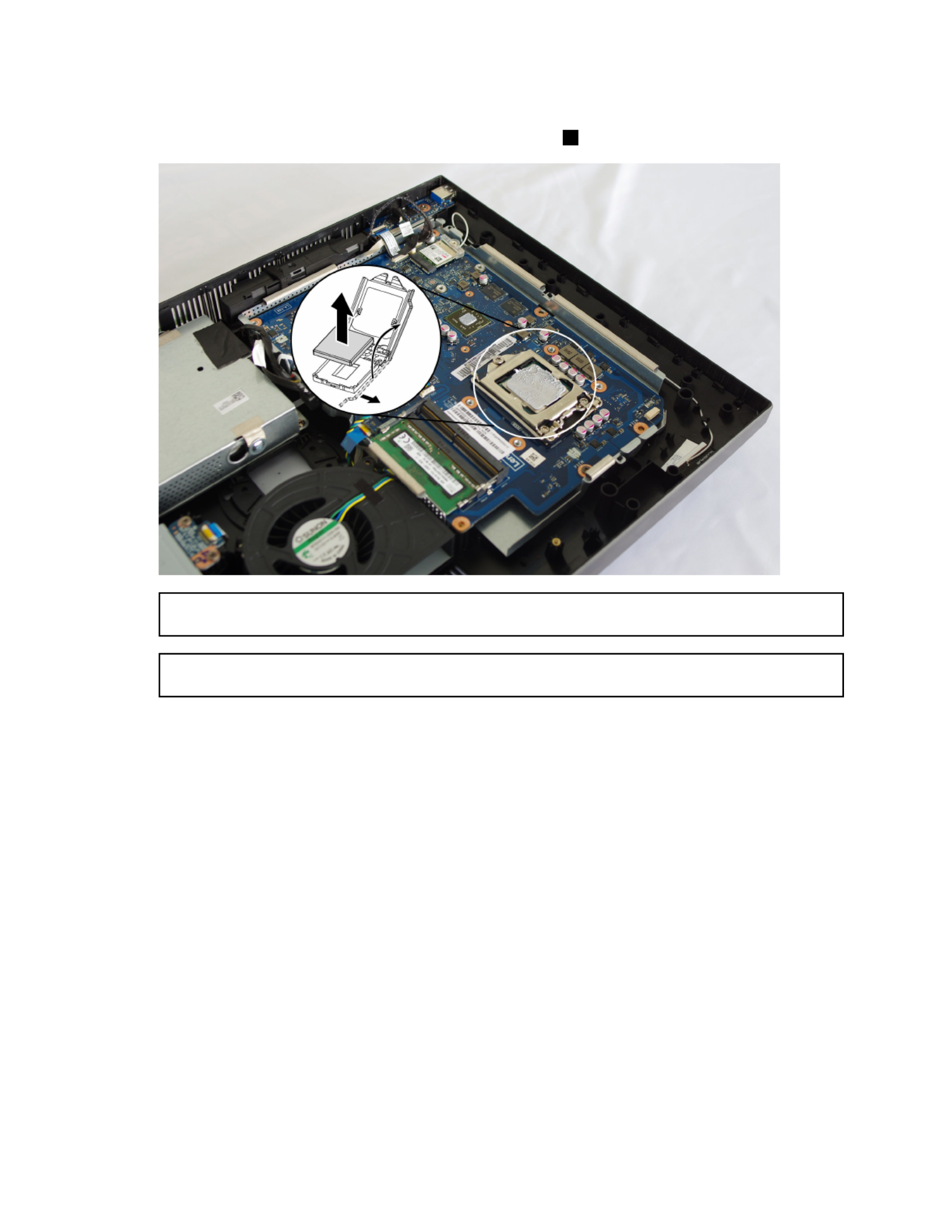
Step5.Liftthesmallhandleandopentheretainer.
Step6.Liftthemicroprocessorstraightupandoutofthesocket.3
Attention:Donottouchthegoldcontactsonthebottomofthemicroprocessor.Whenhandlingthe
microprocessor,touchonlythesides.
Note:Donotdropanythingontothemicroprocessorsocketwhileitisexposed.Thesocketpinsmust
bekeptascleanaspossible.
40ideacentreAll-In-One520(22&24inch)ComputerHardwareMaintenanceManual

Step7.Holdingthesidesofthemicroprocessorwithyourngers,removetheprotectivecover1that
protectsthegoldcontactsonthenewmicroprocessor. 2
Step8.Holdingthesidesofthemicroprocessorwithyourngers,positionthemicroprocessorsothatthe
notchesonthemicroprocessorarealignedwiththetabsinthemicroprocessorsocket.
Important:Toavoiddamagingthemicroprocessorcontacts,keepthemicroprocessorcompletelylevel
whileinstallingitintothesocket.
Step9.Lowerthemicroprocessorstraightdownintoitssocketonthemotherboard.
Step10.Tosecurethemicroprocessorinthesocket,closethemicroprocessorretainerandlockitinto
positionwiththesmallhandle.
Step11.Useathermalgreasesyringetoplace5dropsofgreaseonthetopofthemicroprocessor.Each
dropofgreaseshouldbe0.03ml(3tickmarksonthegreasesyringe).
Step12.Reattachtheheat-sink,EMIcover,middlecover,opticaldrive,standholder,footcoverandstand
base.
Chapter8.Replacinghardware41

Replacingtheharddiskdrive
Attention:Turnoffthecomputerandwait3to5minutestoletitcooldownbeforeremovingthecover.
Note:Itmaybehelpfultoplacethecomputerface-downonasoftatsurfaceforthisprocedure.Lenovo
recommendsthatyouuseablanket,towel,orothersoftclothtoprotectthetouchscreenfromscratches
orotherdamage.
Step1.Removeanymediafromthedrives,shutdowntheoperatingsystem,andturnoffthecomputer
andallattacheddevices.
Step2.Unplugallpowercordsfromelectricaloutlets.
Step3.Disconnectallcablesattachedtothecomputer.Thisincludespowercords,input/output(I/O)
cables,andanyothercablesthatareconnectedtothecomputer.RefertoLocatingconnectors,
controlsandcomponentstolocatethevariousconnectors.
Step4.Removethestandbase.RefertoRemovingthestandbase.
Step5.Removetherearcover.RefertoRemovingtherearcover.
Step6.Pulltheharddiskdriveandbrackettoleft,andthenliftthemup.
Step7.Disconnectthesignalcablefromtheharddiskdrive.
Step8.Removethefourscrewsthatsecuretheharddiskdrivetothebracket.
Step9.Toinstallthenewharddiskdrive:
a.Lineupthenewharddiskdrivewiththebracketandsecureitwithfourscrews.
b.Connectthedataandpowercablestothenewharddiskdrive.
c.Slidetheharddiskdriveandbracketbackintoposition.
Step10.Reattachtherearcoverandstandbase.
42ideacentreAll-In-One520(22&24inch)ComputerHardwareMaintenanceManual

Replacingthesystemfan
Note:T urnoffthecomputerandwait3to5minutestoletitcooldownbeforeremovingthecover.
Note:Itmaybehelpfultoplacethecomputerface-downonasoftflatsurfaceforthisprocedure.Lenovo
recommendsthatyouuseablanket,towel,orothersoftclothtoprotectthecomputerscreenfromscratches
orotherdamage.
Toreplacethesystemfan
Step1.Removeanymediafromthedrives,shutdowntheoperatingsystem,andturnoffthecomputer
andallattacheddevices.
Step2.Unplugallpowercordsfromelectricaloutlets.
Step3.Disconnectallcablesattachedtothecomputer.Thisincludespowercords,input/output(I/O)
cables,andanyothercablesthatareconnectedtothecomputer.RefertoLocatingconnectors,
controlsandcomponentstolocatethevariousconnectors.
Step4.Removethestandbase.RefertoRemovingthestandbase.
Step5.Removetherearcover.RefertoRemovingtherearcover.
Step6.Removethescrewthatsecuresthesystemfantothechassis.
Step7.Disconnectthesystemfanpowercablefromthemotherboard.
Step8.Liftthesystemfanuptoremoveit.
Step9.Toinstallthenewsystemfan:
a.Placethenewsystemfanintoposition,andthensecureittothechassiswithonescrew.
b.Connectthesystemfanpowercabletotheconnectoronthemotherboard.
Step10.Reattachtherearcoverandstandbase.
Chapter8.Replacinghardware43

Replacingtheopticaldrive
Attention:Turnoffthecomputerandwait3to5minutestoletitcooldownbeforeremovingthecover.
Note:Itmaybehelpfultoplacethecomputerface-downonasoftflatsurfaceforthisprocedure.Lenovo
recommendsthatyouuseablanket,towel,orothersoftclothtoprotectthetouchscreenfromscratches
orotherdamage.
Step1.Removeanymediafromthedrives,shutdowntheoperatingsystem,andturnoffthecomputer
andallattacheddevices.
Step2.Unplugallpowercordsfromelectricaloutlets.
Step3.Disconnectallcablesattachedtothecomputer.Thisincludespowercords,input/output(I/O)
cables,andanyothercablesthatareconnectedtothecomputer.RefertoLocatingconnectors,
controlsandcomponentstolocatethevariousconnectors.
Step4.Removethestandbase.RefertoRemovingthestandbase.
Step5.Removetherearcover.RefertoRemovingtherearcover.
Step6.Pushtheopticaldriveoutusingascrewdriveroryourhand.
44ideacentreAll-In-One520(22&24inch)ComputerHardwareMaintenanceManual

Step7.Pushasmallironstick(paperclip)intothesmallholeontheopticaldrivebezelsothatthedisk
springsoutasshown.
Step8.Removetheopticaldrivebezelfromtheopticaldriveasshown.12
Step9.Toinstallthenewopticaldrive:
a.Insertthetabsontheopticaldrivebezelintothecorrespondingholesinthenewopticaldrive,
andthenpushthebezelbackintoposition.
b.Gentlypushthediskforwarduntilitsnapsintoposition.
c.Slidethenewopticaldriveintothedrivebay.
Step10.Reattachtherearcoverandstandbase.
Replacingthememorymodule
Attention:T urnoffthecomputerandwait3to5minutestoletitcooldownbeforeremovingthecover.
Note:Itmaybehelpfultoplacethecomputerface-downonasoftflatsurfaceforthisprocedure.Lenovo
recommendsthatyouuseablanket,towel,orothersoftclothtoprotectthetouchscreenfromscratches
orotherdamage.
Chapter8.Replacinghardware45

Step1.Removeanymediafromthedrives,shutdowntheoperatingsystem,andturnoffthecomputer
andallattacheddevices.
Step2.Unplugallpowercordsfromelectricaloutlets.
Step3.Disconnectallcablesattachedtothecomputer.Thisincludespowercords,input/output(I/O)
cables,andanyothercablesthatareconnectedtothecomputer.RefertoLocatingconnectors,
controlsandcomponentstolocatethevariousconnectors.
Step4.Removethestandbase.RefertoRemovingthestandbase.
Step5.Removetherearcover.RefertoRemovingtherearcover.
Step6.Pushoutthelatchesonbothsidesofthememorysockettoreleasethememorymoduleandgently
pullthememorymoduleupwardtoremoveitfromitssocket.
Step7.
Step8.Toinstallthenewmemorymodule:
a.Positionthenewmemorymoduleoverthememoryslot.Ensurethatthenotch2onthe
memorymodulealignscorrectlywiththeslotkey1inthememorysocket.Pressthememory
moduledownuntilsnapsintoposition.
b.Reinstallthememorycover.
Step9.Reattachtherearcoverandstandbase.
46ideacentreAll-In-One520(22&24inch)ComputerHardwareMaintenanceManual

Replacingthesolidstatedrive
Attention:Turnoffthecomputerandwait3to5minutestoletitcooldownbeforeremovingthecover.
Note:Itmaybehelpfultoplacethecomputerface-downonasoftflatsurfaceforthisprocedure.Lenovo
recommendsthatyouuseablanket,towel,orothersoftclothtoprotectthetouchscreenfromscratches
orotherdamage.
Step1.Removeanymediafromthedrives,shutdowntheoperatingsystem,andturnoffthecomputer
andallattacheddevices.
Step2.Unplugallpowercordsfromelectricaloutlets.
Step3.Disconnectallcablesattachedtothecomputer.Thisincludespowercords,input/output(I/O)
cables,andanyothercablesthatareconnectedtothecomputer.RefertoLocatingconnectors,
controlsandcomponentstolocatethevariousconnectors.
Step4.Removethestandbase.RefertoRemovingthestandbase.
Step5.Removetherearcover.RefertoRemovingtherearcover.
Step6.Removethescrewthatsecurethesolidstatedrivetothemotherboard,andthenslideoutthe
solidstatedrive.3
Step7.Toinstallthenewsolidstatedrive:
a.Insertthesolidstatedriveintotheslot.
b.Securethenewsolidstatedrivetomotherboardwithonescrew.
c.Reinstallthememorycover.
Step8.Reattachtherearcoverandstandbase.
ReplacingtheWi-Ficard
Note:T urnoffthecomputerandwait3to5minutestoletitcooldownbeforeremovingthecover.
Chapter8.Replacinghardware47

Note:Itmaybehelpfultoplacethecomputerface-downonasoftflatsurfaceforthisprocedure.Lenovo
recommendsthatyouuseablanket,towel,orothersoftclothtoprotectthecomputerscreenfromscratches
orotherdamage.
ToreplacetheWi-Ficard:
Step1.Removeanymediafromthedrives,shutdowntheoperatingsystem,andturnoffthecomputer
andallattacheddevices.
Step2.Unplugallpowercordsfromelectricaloutlets.
Step3.Disconnectallcablesattachedtothecomputer.Thisincludespowercords,input/output(I/O)
cables,andanyothercablesthatareconnectedtothecomputer.RefertoLocatingconnectors,
controlsandcomponentstolocatethevariousconnectors.
Step4.Removethestandbase.RefertoRemovingthestandbase.
Step5.Removetherearcover.RefertoRemovingtherearcover.
Step6.RemovethescrewthatsecurestheWi-Ficardtothemotherboard.
Step7.DisconnecttheantennacablesfromtheWi-Ficard.
Step8.PulltheWi-Ficardoutoftheslot.
Step9.T oinstallthenewWi-Ficard:
a.InsertthenewWi-FicardintotheWi-Ficardslot.
b.ConnecttheantennacablestothenewWi-Ficard.
c.SecurenewtheWi-Ficardtothemotherboardwiththescrew.
Step10.Reattachtherearcoverandstandbase.
ReplacingthesideUSBboard
Note:T urnoffthecomputerandwait3to5minutestoletitcooldownbeforeremovingthecover.
48ideacentreAll-In-One520(22&24inch)ComputerHardwareMaintenanceManual

Note:Itmaybehelpfultoplacethecomputerface-downonasoftflatsurfaceforthisprocedure.Lenovo
recommendsthatyouuseablanket,towel,orothersoftclothtoprotectthecomputerscreenfromscratches
orotherdamage.
ToreplacethesideUSBboard:
Step1.Removeanymediafromthedrives,shutdowntheoperatingsystem,andturnoffthecomputer
andallattacheddevices.
Step2.Unplugallpowercordsfromelectricaloutlets.
Step3.Disconnectallcablesattachedtothecomputer.Thisincludespowercords,input/output(I/O)
cables,andanyothercablesthatareconnectedtothecomputer.RefertoLocatingconnectors,
controlsandcomponentstolocatethevariousconnectors.
Step4.Removethestandbase.RefertoRemovingthestandbase.
Step5.Removetherearcover.RefertoRemovingtherearcover.
Step6.DisconnecttheantennacablesfromthesideUSBboard.1
Step7.RemovethescrewthatsecuresthesideUSBboardtothebottomframe.
Step8.LiftupthesideUSBboard.
Step9.T oinstallthenewsideUSBboard:
a.InsertthenewsideUSBboardintothesideUSBboardslot.
b.SecurethenewsideUSBboardtothebottomframewiththescrew.
c.ConnecttheantennacablestothenewsideUSBboard.
Step10.Reattachtherearcoverandstandbase.
Replacingthemotherboard
Note:T urnoffthecomputerandwait3to5minutestoletitcooldownbeforeremovingthecover.
Chapter8.Replacinghardware49

Note:Itmaybehelpfultoplacethecomputerface-downonasoftflatsurfaceforthisprocedure.Lenovo
recommendsthatyouuseablanket,towel,orothersoftclothtoprotectthecomputerscreenfromscratches
orotherdamage.
Toreplacethemotherboard:
Step1.Removeanymediafromthedrives,shutdowntheoperatingsystem,andturnoffthecomputer
andallattacheddevices.
Step2.Unplugallpowercordsfromelectricaloutlets.
Step3.Disconnectallcablesattachedtothecomputer.Thisincludespowercords,input/output(I/O)
cables,andanyothercablesthatareconnectedtothecomputer.RefertoLocatingconnectors,
controlsandcomponentstolocatethevariousconnectors.
Step4.Removethestandbase.RefertoRemovingthestandbase.
Step5.Removetherearcover.RefertoRemovingtherearcover.
Step6.Removethememorymodules.RefertoReplacingthememorymodule.
Step7.Removethesolidstatedrive.RefertoReplacingthesolidstatedrive.
Step8.Removetheheat-sink.RefertoReplacingtheheat-sink.
Step9.RemovetheWi-Ficard.RefertoReplacingtheWi-Ficard.
Step10.Removeallthecablesfromthemotherboard.
Step11.Removetheeightscrewsthatsecurethemotherboardtothechassis,andthenliftthemotherboard
uptoremoveit.
Step12.T oinstallthenewmotherboard:
a.Aligntheeightscrewholesinthenewmotherboardwiththescrewholesinthechassis.
b.Securethenewmotherboardtothechassiswitheightscrews.
c.Connectallthecablestothenewmotherboard.
Step13.Installthefollowingpartstothenewmotherboard:
50ideacentreAll-In-One520(22&24inch)ComputerHardwareMaintenanceManual
•Wi-Ficard
•Heat-sink
•Solidstatedrive
•Memorymodule
Step14.Reattachtherearcoverandstandbase.
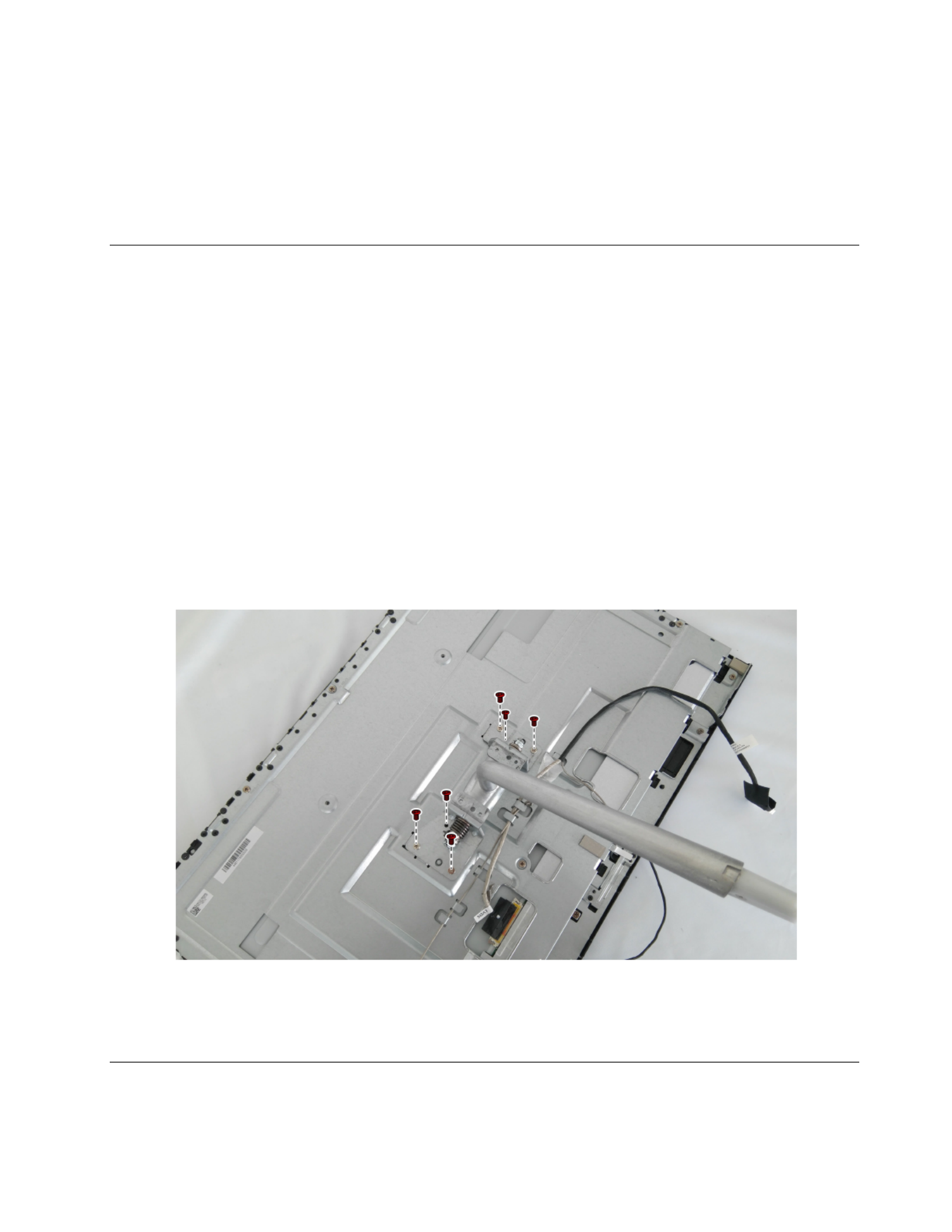
Removingthestandholder
Attention:Turnoffthecomputerandwait3to5minutestoletitcooldownbeforeremovingthecover.
Note:Itmaybehelpfultoplacethecomputerface-downonasoftflatsurfaceforthisprocedure.Lenovo
recommendsthatyouuseablanket,towel,orothersoftclothtoprotectthetouchscreenfromscratches
orotherdamage.
Step1.Removeanymediafromthedrives,shutdowntheoperatingsystem,andturnoffthecomputer
andallattacheddevices.
Step2.Unplugallpowercordsfromelectricaloutlets.
Step3.Disconnectallcablesattachedtothecomputer.Thisincludespowercords,input/output(I/O)
cables,andanyothercablesthatareconnectedtothecomputer.RefertoLocatingconnectors,
controlsandcomponentstolocatethevariousconnectors.
Step4.Removethestandbase.RefertoRemovingthestandbase.
Step5.Removetherearcover.RefertoRemovingtherearcover.
Step6.Removethesixscrews.
Step7.Toreattachthestandholder:
a.Aligntheholesinthestandholderwiththecorrespondingholesinthechassis.
b.Securethestandholdertothechassiswithscrews.
ReplacingtheMicrophonemodule
Note:T urnoffthecomputerandwait3to5minutestoletitcooldownbeforeremovingthecover.
Chapter8.Replacinghardware51

Note:Itmaybehelpfultoplacethecomputerface-downonasoftflatsurfaceforthisprocedure.Lenovo
recommendsthatyouuseablanket,towel,orothersoftclothtoprotectthecomputerscreenfromscratches
orotherdamage.
Toreplacethespeakersystem:
Step1.Removeanymediafromthedrives,shutdowntheoperatingsystem,andturnoffthecomputer
andallattacheddevices.
Step2.Unplugallpowercordsfromelectricaloutlets.
Step3.Disconnectallcablesattachedtothecomputer.Thisincludespowercords,input/output(I/O)
cables,andanyothercablesthatareconnectedtothecomputer.RefertoLocatingconnectors,
controlsandcomponentstolocatethevariousconnectors.
Step4.Removethestandbase.RefertoRemovingthestandbase.
Step5.Removetherearcover.RefertoRemovingtherearcover.
Step6.Disconnectthemicrophonemodulecablefromtheconnectoronthemotherboard,andremovethe
screwthatsecuresthemicrophonemoduletothemotherboard.
Step7.Liftupthemicrophonemoduletoremoveit.
Step8.T oinstallthenewmicrophonemodule:
a.Securethenewmicrophonemoduletothemotherboardwiththescrew.
b.Connectthecabletothemotherboard.
Step9.Reattachrearcoverandstandbase.
Replacingthespeakersystem
Note:T urnoffthecomputerandwait3to5minutestoletitcooldownbeforeremovingthecover.
52ideacentreAll-In-One520(22&24inch)ComputerHardwareMaintenanceManual

Note:Itmaybehelpfultoplacethecomputerface-downonasoftflatsurfaceforthisprocedure.Lenovo
recommendsthatyouuseablanket,towel,orothersoftclothtoprotectthecomputerscreenfromscratches
orotherdamage.
Toreplacethespeakersystem:
Step1.Removeanymediafromthedrives,shutdowntheoperatingsystem,andturnoffthecomputer
andallattacheddevices.
Step2.Unplugallpowercordsfromelectricaloutlets.
Step3.Disconnectallcablesattachedtothecomputer.Thisincludespowercords,input/output(I/O)
cables,andanyothercablesthatareconnectedtothecomputer.RefertoLocatingconnectors,
controlsandcomponentstolocatethevariousconnectors.
Step4.Removethestandbase.RefertoRemovingthestandbase.
Step5.Removetherearcover.RefertoRemovingtherearcover.
Step6.Disconnectthespeakersystemcablefromtheconnectoronthemotherboard,andthenslidethe
rubberscrewsofthespeakersystemoutofthescrewslots.
Step7.Liftupthespeakersystemtoremoveit.
Step8.T oinstallthenewspeakersystem:
a.Slideintherubberscrewsofthenewspeakersystemintothescrewslotsinthechassis.
b.Connectthecabletothemotherboard.
Step9.Reattachrearcover,andstandbase.
ReplacingtheLCDpanelmodule
Note:T urnoffthecomputerandwait3to5minutestoletitcooldownbeforeremovingthecover.
Chapter8.Replacinghardware53

Note:Itmaybehelpfultoplacethecomputerface-downonasoftflatsurfaceforthisprocedure.Lenovo
recommendsthatyouuseablanket,towel,orothersoftclothtoprotectthecomputerscreenfromscratches
orotherdamage.
ToreplacetheLCDpanelmodule:
Step1.Removeanymediafromthedrives,shutdowntheoperatingsystem,andturnoffthecomputer
andallattacheddevices.
Step2.Unplugallpowercordsfromelectricaloutlets.
Step3.Disconnectallcablesattachedtothecomputer.Thisincludespowercords,input/output(I/O)
cables,andanyothercablesthatareconnectedtothecomputer.RefertoLocatingconnectors,
controlsandcomponentstolocatethevariousconnectors.
Step4.Removethestandbase.RefertoRemovingthestandbase.
Step5.Removetherearcover.RefertoRemovingtherearcover.
Step6.Removethestandholder.RefertoRemovingthestandholder.
Step7.Removethememorymodules.RefertoReplacingthememorymodule.
Step8.Removethesolidstatedrive.RefertoReplacingthesolidstatedrive.
Step9.Removetheheat-sink.RefertoReplacingtheheat-sink.
Step10.RemovetheCPU.RefertoReplacingtheCPU.
Step11.Removethemotherboard.RefertoReplacingthemotherboard.
Step12.RemovetheLVDScableandconvertercablefromtheconnectorsintheLCDpanel.
Step13.RemovethenineteenscrewsthatsecurethemainframetotheLCDpanel.
54ideacentreAll-In-One520(22&24inch)ComputerHardwareMaintenanceManual

Step14.Liftupthemainframetoremoveit.
Step15.Ifyourdeviceisatouchcomputer,disconnectthetouchcablefromtheconnectoronthe
motherboard.Otherwise,skipthisstep.RefertoLocatingconnectors,controlsandcomponentsto
locatethetouchconnector.
Step16.T oinstallthenewtheLCDpanelmodule:
a.AlignthenewLCDpanelwiththemainframe.
b.SecurethenewLCDpaneltothemainframewithnineteenscrews.
c.Connectthetouch(touchmodelonly),LVDSandconvertercablestotheconnectorsinthe
newLCDpanel.
Step17.Reattachallotherremovedparts.
Chapter8.Replacinghardware55

56ideacentreAll-In-One520(22&24inch)ComputerHardwareMaintenanceManual
Produkt Specifikationer
| Mærke: | Lenovo |
| Kategori: | Skrivebord |
| Model: | Ideacentre AIO 520-24ARR |
Har du brug for hjælp?
Hvis du har brug for hjælp til Lenovo Ideacentre AIO 520-24ARR stil et spørgsmål nedenfor, og andre brugere vil svare dig
Skrivebord Lenovo Manualer

23 November 2024
23 November 2024
10 Oktober 2024
10 Oktober 2024
17 September 2024
10 September 2024
9 September 2024
31 August 2024
28 August 2024
13 August 2024
Skrivebord Manualer
- Skrivebord Ikea
- Skrivebord Acer
- Skrivebord Sony
- Skrivebord Samsung
- Skrivebord Panasonic
- Skrivebord Apple
- Skrivebord Sharp
- Skrivebord HP
- Skrivebord Asus
- Skrivebord Gigabyte
- Skrivebord Toshiba
- Skrivebord InFocus
- Skrivebord Asrock
- Skrivebord Butler
- Skrivebord Optoma
- Skrivebord Zaor
- Skrivebord JYSK
- Skrivebord Parisot
- Skrivebord United Office
- Skrivebord Razer
- Skrivebord Medion
- Skrivebord Haier
- Skrivebord Seagate
- Skrivebord Vtech
- Skrivebord Tripp Lite
- Skrivebord Packard Bell
- Skrivebord Microsoft
- Skrivebord Fellowes
- Skrivebord Digitus
- Skrivebord Genesis
- Skrivebord Techly
- Skrivebord Viewsonic
- Skrivebord Dell
- Skrivebord ELO
- Skrivebord Fujitsu
- Skrivebord Cooler Master
- Skrivebord MSI
- Skrivebord NEC
- Skrivebord Bush
- Skrivebord TrekStor
- Skrivebord ECS
- Skrivebord SPC
- Skrivebord ZTE
- Skrivebord Kobo
- Skrivebord Kramer
- Skrivebord Onyx
- Skrivebord Vorago
- Skrivebord EMachines
- Skrivebord Axis
- Skrivebord Faytech
- Skrivebord Intel
- Skrivebord Sharkoon
- Skrivebord Supermicro
- Skrivebord BDI
- Skrivebord Kogan
- Skrivebord LC-Power
- Skrivebord Planar
- Skrivebord Overdrive
- Skrivebord Zotac
- Skrivebord Moxa
- Skrivebord Alienware
- Skrivebord Aeris
- Skrivebord Maxdata
- Skrivebord Targa
- Skrivebord Peaq
- Skrivebord Shuttle
- Skrivebord Promethean
- Skrivebord Foxconn
- Skrivebord Ibm
- Skrivebord Advantech
- Skrivebord Pelco
- Skrivebord Xtech
- Skrivebord MP
- Skrivebord Elitegroup
- Skrivebord X Rocker
- Skrivebord Smart Things
- Skrivebord System76
- Skrivebord Zoostorm
- Skrivebord Bestar
- Skrivebord Cybernet
- Skrivebord Altra
- Skrivebord Dell Wyse
- Skrivebord AOpen
- Skrivebord ProDVX
- Skrivebord NComputing
- Skrivebord MvixUSA
- Skrivebord Seville Classics
- Skrivebord AIS
- Skrivebord Wyse
- Skrivebord Mount-It!
Nyeste Skrivebord Manualer

1 April 2025
4 Marts 2025

18 Februar 2025

15 Februar 2025
14 Februar 2025
14 Februar 2025
14 Februar 2025
14 Februar 2025

10 Januar 2025
6 Januar 2025