Lenovo ThinkCentre 7638 Manual
Lenovo
Skrivebord
ThinkCentre 7638
Læs nedenfor 📖 manual på dansk for Lenovo ThinkCentre 7638 (84 sider) i kategorien Skrivebord. Denne guide var nyttig for 7 personer og blev bedømt med 4.5 stjerner i gennemsnit af 2 brugere
Side 1/84


ThinkCentre
User Guide

Note
Before using this information and the product it supports, be sure to read and understand the ThinkCentre Safety and
Warranty Guide and “Notices,” on page 69.
Third Edition (October 2009)
© Copyright Lenovo 2009.
LENOVO products, data, computer software, and services have been developed exclusively at private expense and
are sold to governmental entities as commercial items as defined by 48 C.F.R. 2.101 with limited and restricted
rights to use, reproduction and disclosure.
LIMITED AND RESTRICTED RIGHTS NOTICE: If products, data, computer software, or services are delivered
pursuant a General Services Administration GSA contract, use, reproduction, or disclosure is subject to restrictions″ ″
set forth in Contract No. GS-35F-05925.

Contents
Important safety information . . . . . . v
Chapter 1. Product overview . . . . . . 1
Features . . . . . . . . . . . . . . . . 1
Specifications . . . . . . . . . . . . . . 4
Software overview . . . . . . . . . . . . 5
Software provided with your Windows operating
system . . . . . . . . . . . . . . . 5
Locations . . . . . . . . . . . . . . . 7
Locating connectors on the front of your computer 7
Locating connectors on the rear of your computer 8
Locating components . . . . . . . . . . 10
Locating parts on the system board . . . . . 11
Chapter 2. Installing options and
replacing hardware . . . . . . . . . 13
Handling static-sensitive devices . . . . . . . 13
Installing options and replacing hardware . . . . 13
Installing external options . . . . . . . . 14
Opening the computer cover . . . . . . . 14
Accessing the system board components and
drives . . . . . . . . . . . . . . . 16
Installing or replacing a memory module . . . 16
Installing or replacing a PCI card . . . . . . 18
Installing internal drives . . . . . . . . . 20
Replacing the hard disk drive . . . . . . . 24
Replacing the optical drive . . . . . . . . 27
Replacing the battery . . . . . . . . . . 28
Replacing the power supply assembly . . . . 30
Replacing the heat sink and fan assembly . . . 32
Replacing the card reader. . . . . . . . . 34
Replacing the keyboard . . . . . . . . . 35
Replacing the mouse . . . . . . . . . . 35
Completing the parts replacement . . . . . . 36
Installing security features . . . . . . . . . 37
Integrated cable lock . . . . . . . . . . 38
Password protection . . . . . . . . . . 38
Erasing lost or forgotten passwords (clearing
CMOS) . . . . . . . . . . . . . . . 38
Chapter 3. Recovery information . . . 41
Creating and using recovery media . . . . . . 41
Creating recovery media . . . . . . . . . 41
Using recovery media . . . . . . . . . . 42
Performing backup and recovery operations . . . 42
Performing a backup operation . . . . . . . 43
Performing a recovery operation . . . . . . 43
Using the Rescue and Recovery workspace . . . . 44
Creating and using rescue media . . . . . . . 45
Creating rescue media . . . . . . . . . . 45
Using rescue media. . . . . . . . . . . 45
Creating and using a recovery repair diskette . . . 46
Creating a recovery repair diskette . . . . . 46
Using a recovery repair diskette . . . . . . 46
Installing or reinstalling device drivers . . . . . 47
Setting a rescue device in the startup sequence . . 48
Solving recovery problems . . . . . . . . . 48
Chapter 4. Using the Setup Utility . . . 49
Starting the Setup Utility program. . . . . . . 49
Viewing and changing settings . . . . . . . . 49
Using passwords . . . . . . . . . . . . 49
Password considerations . . . . . . . . . 50
Power-On Password . . . . . . . . . . 50
Administrator Password . . . . . . . . . 50
Hard Disk User Password . . . . . . . . 50
Setting, changing, and deleting a password. . . 50
Enabling or disabling a device . . . . . . . . 51
Selecting a startup device . . . . . . . . . . 51
Selecting a temporary startup device . . . . . 51
Selecting or changing the startup device sequence 52
Exiting from the Setup Utility program . . . . . 52
Chapter 5. Updating system programs 53
Using system programs . . . . . . . . . . 53
Updating (flashing) BIOS from a disc . . . . . . 53
Updating (flashing) BIOS from your operating
system . . . . . . . . . . . . . . . . 54
Recovering from a POST/BIOS update failure . . . 54
Chapter 6. Troubleshooting and
diagnostics. . . . . . . . . . . . . 57
Basic troubleshooting . . . . . . . . . . . 57
Diagnostic programs . . . . . . . . . . . 59
Lenovo ThinkVantage Toolbox . . . . . . . 59
Lenovo System Toolbox . . . . . . . . . 59
PC-Doctor for Rescue and Recovery . . . . . 60
PC-Doctor for DOS . . . . . . . . . . . 60
Cleaning the mouse . . . . . . . . . . . 61
Optical mouse . . . . . . . . . . . . 61
Non-optical mouse . . . . . . . . . . . 61
Chapter 7. Getting information, help,
and service. . . . . . . . . . . . . 63
Information resources . . . . . . . . . . . 63
Online Books folder . . . . . . . . . . 63
Lenovo ThinkVantage Tools . . . . . . . . 63
ThinkVantage Productivity Center . . . . . . 64
Lenovo Welcome . . . . . . . . . . . 64
Access Help . . . . . . . . . . . . . 64
Safety and Warranty . . . . . . . . . . 64
Lenovo Web site (http://www.lenovo.com). . . 65
Help and service . . . . . . . . . . . . 65
Using the documentation and diagnostic
programs . . . . . . . . . . . . . . 65
Calling for service . . . . . . . . . . . 65
Using other services . . . . . . . . . . 66
Purchasing additional services . . . . . . . 67
© Copyright Lenovo 2009 iii

Appendix. Notices . . . . . . . . . . 69
Television output notice . . . . . . . . . . 70
European conformance CE mark . . . . . . . 70
Trademarks . . . . . . . . . . . . . . 70
Index . . . . . . . . . . . . . . . 71
iv User Guide

Important safety information
CAUTION:
Before using this manual, be sure to read and understand all the related safety
information for this product. Refer to the ThinkCentre Safety and Warranty Guide
that you received with this product for the latest safety information. Reading
and understanding this safety information reduces the risk of personal injury
and or damage to your product.
If you no longer have a copy of the ThinkCentre Safety and Warranty Guide, you can
obtain a Portable Document Format (PDF) version from the Lenovo
®Support Web
site at:
http://www.lenovo.com/support
© Copyright Lenovo 2009 v

vi User Guide

Chapter 1. Product overview
This chapter describes the computer features, specifications, preinstalled software
programs, and part and connector locations.
Features
This section provides an overview of the computer features.
System information
The following information covers a variety of models. For information about
your specific model, use the Setup Utility program. See Chapter 4, “Using the
Setup Utility,” on page 49.
Microprocessor
vIntel®Celeron®processor
vIntel Core™2 Duo processor
vIntel Core 2 Quad processor
vIntel Pentium®dual-core processor
vInternal cache (size varies by model type)
Memory
vSupports up to four double data rate 3 dual inline memory modules (DDR3
DIMMs)
Internal drives
vCard reader (some models)
vOptical drive
vSATA (Serial Advanced Technology Attachment) internal hard disk drive (some
models)
vSolid State Drive (SSD) (some models)
Video subsystem
vIntegrated graphics card for a VGA (Video Graphics Array) connector and
DisplayPort connector
vPCI (Peripheral Component Interconnect) Express x16 graphics card slot on the
system board for a discrete graphics card
© Copyright Lenovo 2009 1

Audio subsystem
vHigh Definition (HD) with ADI 1882 Audio Codec
vAudio line-in connector, audio line-out connector, and microphone connector on
the rear panel
vMicrophone connector and headphone connector on the front panel
vInternal speaker (some models)
Connectivity
v10/100/1000 Mbps integrated Ethernet controller
vPCI V.90 Data/Fax modem (some models)
System management features
vAbility to store power-on self-test (POST) hardware test results
vAutomatic power-on startup
vAlert Standard Format 2.0
vIntel Active Management Technology (AMT) (some models)
vIntel matrix storage manager
vPreboot Execution Environment (PXE) and Dynamic Host Configuration Protocol
(DHCP)
vRemote Administration
vSecure Managed Client (SMC) (some models)
vSystem Management (SM) Basic Input/Output System (BIOS) and SM software
vWake on LAN
vWake on Ring (in the Setup Utility program, this feature is called Serial Port
Ring Detect for an external modem)
Input/Output (I/O) features
v9-pin serial port (one standard and one optional)
vEight USB connectors (two on the front panel and six on the rear panel)
vEthernet connector
vOne DisplayPort connector
vOne eSATA connector
vStandard keyboard connector (some models)
vStandard mouse connector (some models)
vThree audio connectors (audio line-in connector, audio line-out connector, and
microphone connector) on the rear panel
vTwo audio connectors (microphone connector and headphone connector) on the
front panel
vVGA monitor connector
Expansion
vOne card reader
vOne hard disk drive bay
vOne optical drive bay
vOne PCI card slot
vOne PCI Express x16 graphics card slot
2User Guide

Power supply
v280-watt auto-sensing power supply
vAutomatic 50/60 Hz input frequency switching
vAdvanced Configuration and Power Interface (ACPI) support
Security features
vComputrace
vCover presence switch (also called intrusion switch, some models)
vHard Disk User Password
vKeyboard with fingerprint reader (some models)
vPower-On Password (POP) and Administrator Password for BIOS access
vSerial and parallel port I/O control
vStartup sequence control
vStartup without diskette drive, keyboard, or mouse
vSupport for the addition of an integrated cable lock (Kensington lock)
vSupport to enable or disable a device
vTrusted Platform Module (TPM)
vUnattended start mode
vUSB switch on/off individually
Software programs, preinstalled
Your computer might come with preinstalled software programs. If it does, an
operating system, device drivers to support built-in features, and other support
programs are included. For more information, see “Software overview” on page 5.
Operating system, preinstalled
vMicrosoft®Windows®7
vMicrosoft Windows Vista®
vMicrosoft Windows XP Professional
(preinstalled through downgrade rights in Windows 7 Professional, Windows 7
Ultimate, Windows Vista Business, or Windows Vista Ultimate)
Operating systems, certified or tested for compatibility
1(varies by model type)
vLinux®
1. The operating systems listed here are being certified or tested for compatibility at the time this publication goes to press.
Additional operating systems might be identified by Lenovo as compatible with your computer following the publication of this
booklet. Corrections and additions to this list are subject to change. To determine if an operating system has been certified or
tested for compatibility, check the Web site of the operating system vendor.
Chapter 1. Product overview 3

Specifications
This section lists the physical specifications for your computer.
Dimensions
Width: 317 mm (12.48 inches)
Height: 99 mm (3.90 inches)
Depth: 355 mm (13.98 inches)
Weight
Maximum configuration as shipped: 7.5 kg (16.53 lbs)
Environment
Air temperature:
Operating: 10° to 35°C (50° to 95°F)
Non-operating: -40° to 60°C (-40° to 140°F) (with package)
Non-operating: -10° to 60°C (14° to 140°F) (without package)
Humidity:
Operating: 10% to 80% (10% per hour, non condensing)
Non-operating: 10% to 90% (10% per hour, non condensing)
Maximum altitude:
Operating: -50 to 10 000 ft (-15.2 to 3 048 m)
Non-operating: -50 to 35 000 ft (-15.2 to 10 668 m)
Electrical input
Input voltage:
Low range:
Minimum: 100 V ac
Maximum: 127 V ac
Input frequency range: 50 to 60 Hz
Voltage-selection switch setting: 115 V ac
High range:
Minimum: 200 V ac
Maximum: 240 V ac
Input frequency range: 50 to 60 Hz
Voltage-selection switch setting: 230 V ac
4User Guide

Software overview
This section describes the software preinstalled on the computers that have an
internal hard disk drive and an operating system from Lenovo.
Software provided with your Windows operating system
This section describes the Windows applications included with your computer.
Software provided by Lenovo
The following software programs are provided by Lenovo to help you improve
productivity and reduce the cost associated with maintaining your computer.
Software programs provided with your computer might vary depending on your
model type and preinstalled operating system.
Lenovo ThinkVantage Tools: The Lenovo ThinkVantage
®Tools program guides
you to a host of information sources and provides easy access to various tools to
help you work more easily and securely. For more information, see “Lenovo
ThinkVantage Tools” on page 63.
Note: The Lenovo ThinkVantage Tools program is only available on computers
preinstalled with Windows 7 from Lenovo.
ThinkVantage Productivity Center: The ThinkVantage Productivity Center
program guides you to a host of information and tools to help you set up,
understand, maintain, and enhance your computer.
Note: The ThinkVantage Productivity Center program is only available on
computers preinstalled with Windows Vista or Windows XP from Lenovo.
ThinkVantage Rescue and Recovery: The ThinkVantage Rescue and Recovery
®
(RnR) program is a one button recovery and restore solution that includes a set of
self recovery tools to help users diagnose computer problems, get help, and
recover from system crashes quickly, even if the primary operating system will not
start.
ThinkVantage Client Security Solution: The ThinkVantage Client Security
Solution (CSS) program is available on select Lenovo computers. It helps protect
your information, including vital security information like passwords, encryption
keys, and electronic credentials, while guarding against unauthorized user access
to data.
Note: The ThinkVantage Client Security Solution program is only available on
computers preinstalled with Windows Vista or Windows XP from Lenovo.
Password Manager: The Password Manager program helps you automatically
capture and fill in authentication information for Windows applications and Web
sites.
Note: The Password Manager program is only available on computers preinstalled
with Windows 7 from Lenovo.
ThinkVantage System Update: The ThinkVantage System Update (TVSU)
program helps you keep the software on your system up-to-date, by downloading
and installing software packages (TVT applications, device drivers, BIOS flashes,
and other third party applications). Some examples of software that you should
Chapter 1. Product overview 5

keep updated are programs provided by Lenovo, such as the Rescue and Recovery
program and the Productivity Center program.
ThinkVantage Power Manager: The ThinkVantage Power Manager program
provides convenient, flexible, and complete power management for your
ThinkCentre®computer. By using the ThinkVantage Power Manager program, you
can adjust your power settings to achieve the best balance between system
performance and power saving.
Fingerprint Software: The integrated fingerprint reader provided on some
keyboards enables you to enroll your fingerprint and associate it with your
power-on password, hard disk drive password, and Windows password. As a
result, fingerprint authentication can replace passwords and enable simple and
secure user access. A fingerprint reader keyboard is available with select computers
or can be purchased for computers that support this option.
Lenovo ThinkVantage Toolbox
The Lenovo ThinkVantage Toolbox program helps you maintain your computer,
improve computing security, diagnose computer problems, get familiar with the
innovative technologies provided by Lenovo, and get more information about your
computer. See “Lenovo ThinkVantage Toolbox” on page 59 for detailed
information.
Note: The Lenovo ThinkVantage Toolbox program is only available on computers
preinstalled with Windows 7 from Lenovo.
Lenovo System Toolbox
The Lenovo System Toolbox diagnostic program is preinstalled on your hard disk
drive. This diagnostic program works through the Windows operating system to
diagnose hardware problems and report operating-system-controlled settings that
can cause hardware failures. See “Lenovo System Toolbox” on page 59 for more
information.
Note: The Lenovo System Toolbox program is only available on computers
preinstalled with Windows Vista or Windows XP from Lenovo.
PC-Doctor for Rescue and Recovery
The PC-Doctor for Rescue and Recovery diagnostic program is preinstalled on
your hard disk drive. It is part of the Rescue and Recovery workspace on each
Lenovo computer to diagnose hardware problems and report operating-system-
controlled settings that can cause hardware failures. Use the PC-Doctor for Rescue
and Recovery if you are unable to start the Windows operating system. See
“PC-Doctor for Rescue and Recovery” on page 60 for more information.
Adobe Reader
The Adobe Reader is a tool used to view, print, and search PDF documents.
See “Online Books folder” on page 63 for more information about accessing the
online books and the Lenovo Web site.
Antivirus software
Your computer comes with antivirus software that you can use to detect and
eliminate viruses. Lenovo provides a full version of antivirus software on your
hard disk drive with a free 30-day subscription. After 30 days, you must renew the
license to continue receiving the antivirus program updates.
6User Guide

Locations
Locating connectors on the front of your computer
Figure 1 shows the locations of the connectors on the front of your computer.
Note: Not all computer models have the following connectors.
1 3USB connector Headphone connector
2 4Microphone connector USB connector
Figure 1. Front connector locations
Chapter 1. Product overview 7

Locating connectors on the rear of your computer
Figure 2 shows the locations of the connectors on the rear of your computer. Some
connectors on the rear of your computer are color-coded to help you determine
where to connect the cables on your computer.
1 9Serial port (some models) Standard mouse connector (some models)
2 10Power cord connector DisplayPort connector
3 11Audio line-in connector USB connectors (2)
4 12Audio line-out connector eSATA connector
5 13Microphone connector USB connectors (4)
6 14Serial port Ethernet connector
7 15VGA monitor connector PCI Express x16 graphics card slot
8 Standard keyboard connector (some
models)
16 PCI card slot
Figure 2. Rear connector locations
8User Guide

Connector Description
Audio line-in connector Used to receive audio signals from an external audio device,
such as a stereo system. When you attach an external audio
device, a cable is connected between the audio line-out
connector of the device and the audio line-in connector of the
computer.
Audio line-out connector Used to send audio signals from the computer to external
devices, such as powered stereo speakers (speakers with
built-in amplifiers), headphones, multimedia keyboards, or the
audio line-in connector on a stereo system or other external
recording device.
DisplayPort connector Used to attach a high-performance monitor, a direct-drive
monitor, or other devices that use a DisplayPort connector.
eSATA connector Use this external Serial Advanced Technology Attachment
(eSATA) connector to attach an external hard disk drive.
Ethernet connector Used to attach an Ethernet cable for a local area network
(LAN).
Note: To operate the computer within FCC Class B limits, use
a Category 5 Ethernet cable.
Microphone connector Used to attach a microphone to your computer when you want
to record sound or if you use speech-recognition software.
Serial port Used to attach an external modem, a serial printer, or other
devices that use a 9-pin serial port.
Standard keyboard
connector
Used to attach a keyboard that uses a standard keyboard
connector.
Standard mouse connector Used to attach a mouse, a trackball, or other pointing devices
that use a standard mouse connector.
USB connector Used to attach a device that requires a Universal Serial Bus
(USB) connector, such as a USB keyboard, a USB mouse, a USB
scanner or a USB printer. If you have more than eight USB
devices, you can purchase a USB hub, which you can use to
connect additional USB devices.
VGA monitor connector Used to attach a VGA monitor or other devices that use a VGA
monitor connector.
Chapter 1. Product overview 9

Locating components
Figure 3 shows the locations of the various components in your computer. To open
the computer cover, see “Opening the computer cover” on page 14.
1 4Hard disk drive (some models) Optical drive
2 Microprocessor, heat sink and fan
assembly
5 Memory slots (4)
3 6Internal speaker (some models) Power supply assembly
Figure 3. Component locations
10 User Guide

Locating parts on the system board
Figure 4 shows the locations of the parts on the system board.
1 11PCI card slot Memory slots (4)
2 PCI Express x16 graphics card slot 24-pin power connector12
3 13Battery Serial (COM 2) connector
4 14Internal speaker connector Front audio connector
5 Cover presence switch connector
(Intrusion switch connector) (some
models)
15 SATA connectors (2)
6 Microprocessor fan connector System fan connector16
7 17Thermal sensor connector Front USB connector 1
8 Microprocessor Front USB connector 218
9 194-pin power connector Clear CMOS (Complementary Metal Oxide
Semiconductor)/Recovery jumper
10 20Front panel connector Power fan connector
Figure 4. System board parts locations
Chapter 1. Product overview 11

12 User Guide

Chapter 2. Installing options and replacing hardware
This chapter provides instructions for installing options and replacing hardware for
your computer. You can expand the capabilities of your computer by adding
memory modules, PCI cards, or drives. When installing or replacing an option, use
these instructions along with the instructions that come with the option.
Important: Before you install or replace any option, be sure to read and
understand the "Important safety information" in the ThinkCentre Safety
and Warranty Guide. The precautions and guidelines will help you work
safely.
Handling static-sensitive devices
Do not open the static-protective package containing the new part until the
defective part has been removed from the computer and you are ready to install
the new part. Static electricity, although harmless to you, can seriously damage
computer components and parts.
When you handle parts and other computer components, take these precautions to
avoid static-electricity damage:
v Limit your movement. Movement can cause static electricity to build up around
you.
v Always handle parts and other computer components carefully. Handle PCI
cards, memory modules, system boards, and microprocessors by the edges.
Never touch any exposed circuitry.
v Prevent others from touching the parts and other computer components.
v Before you replace a new part, touch the static-protective package containing the
part to a metal expansion-slot cover or other unpainted metal surface on the
computer for at least two seconds. This reduces static electricity in the package
and your body.
v When possible, remove the new part from the static-protective packaging, and
install it directly in the computer without setting the part down. When this is
not possible, place the static-protective package that the part came in on a
smooth, level surface and place the part on it.
v Do not place the part on the computer cover or other metal surface.
Installing options and replacing hardware
This section provides introductions for installing options and replacing hardware
for your computer. When installing or replacing an option, use these instructions
along with the instructions that come with the option.
Attention
Do not open your computer or attempt any repair before reading and understanding the
“Important safety information” in the ThinkCentre Safety and Warranty Guide that came with
your computer. To obtain a copy of the ThinkCentre Safety and Warranty Guide, go to:
http://www.lenovo.com/support
Note: Use only computer parts provided by Lenovo.
© Copyright Lenovo 2009 13
Installing external options
External speakers, a printer, or a scanner can be connected to your computer. For
some external options, you must install additional software in addition to making
the physical connection. When installing an external option, see “Locating
connectors on the front of your computer” on page 7 and “Locating connectors on
the rear of your computer” on page 8 to identify the required connector, and then
use the instructions that come with the option to help you make the connection
and install any software or device drivers that are required for the option.
Opening the computer cover
Attention
Do not open your computer or attempt any repair before reading and understanding the
“Important safety information” in the ThinkCentre Safety and Warranty Guide that came with
your computer. To obtain a copy of the ThinkCentre Safety and Warranty Guide, go to:
http://www.lenovo.com/support
This section provides instructions on how to open the computer cover.
CAUTION:
Turn off the computer and wait three to five minutes to let the computer cool
before opening the computer cover.
Important
Be sure to read and understand “Handling static-sensitive devices” on page
13 before opening the computer cover.
To open the computer cover:
1. Remove any media from the drives, shut down your operating system, and
turn off all attached devices and the computer.
2. Unplug all power cords from electrical outlets.
3. Disconnect the cables attached to the computer. This includes power cords,
input/output (I/O) cables, and any other cables that are connected to the
computer. See “Locating connectors on the front of your computer” on page 7
and “Locating connectors on the rear of your computer” on page 8.
4. Remove any locking devices, such as a cable lock that secures the computer
cover.
14 User Guide

5. Press the buttons on the sides of the computer and pivot the computer cover
upward to open.
Figure 5. Opening the computer cover
Chapter 2. Installing options and replacing hardware 15

Accessing the system board components and drives
This section provides instructions on how to access the system board components
and drives.
To access the system board components and drives:
1. Open the computer cover. See “Opening the computer cover” on page 14.
2. On some models, you might need to pivot the optical drive bay assembly
upward and remove the hard disk drive to access the internal components. See
“Replacing the hard disk drive” on page 24.
Notes:
a. Make sure you note the locations of any cables that you disconnect from the
drives or the system board.
b. Make sure the hard disk drive assembly is in the latched down position
before closing the computer cover to prevent damage to the hard disk drive.
Installing or replacing a memory module
Attention
Do not open your computer or attempt any repair before reading and understanding the
“Important safety information” in the ThinkCentre Safety and Warranty Guide that came with
your computer. To obtain a copy of the ThinkCentre Safety and Warranty Guide, go to:
http://www.lenovo.com/support
This section provides instructions on how to install or replace a memory module.
Your computer has four slots for installing or replacing DDR3 DIMMs (double data
rate 3 dual inline memory modules) that provide up to a maximum of 8 GB
system memory. When installing or replacing a memory module, use 1 GB or 2 GB
DDR3 DIMMs in any combination up to a maximum of 8 GB.
Figure 6. Pivoting the optical drive bay assembly
16 User Guide

To install or replace a memory module:
1. Open the computer cover. See “Opening the computer cover” on page 14.
2. Pivot the optical drive bay assembly upward to access the memory slots. See
“Accessing the system board components and drives” on page 16.
3. Remove any parts that might prevent your access to the memory slots.
4. Locate the memory slots.
5. Open the retaining clips.
If you are replacing an old memory module, open the retaining clips and
remove the memory module being replaced as shown.
Figure 7. Opening the retaining clips
Figure 8. Removing the old memory module
Chapter 2. Installing options and replacing hardware 17
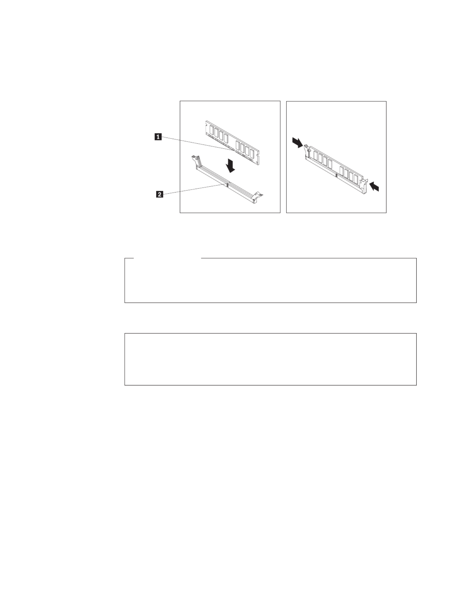
6. Position the new memory module over the memory slot. Make sure that the
notch on the memory module aligns correctly with the slot key on the1 2
system board. Push the memory module straight down into the slot until the
retaining clips close.
What to do next:
v To work with another option, go to the appropriate section.
v To complete the installation, go to “Completing the parts replacement” on
page 36.
Installing or replacing a PCI card
Attention
Do not open your computer or attempt any repair before reading and understanding the
“Important safety information” in the ThinkCentre Safety and Warranty Guide that came with
your computer. To obtain a copy of the ThinkCentre Safety and Warranty Guide, go to:
http://www.lenovo.com/support
This section provides instructions on how to install or replace a PCI card. Your
computer has one standard PCI card slot and one PCI Express x16 graphics card
slot.
Figure 9. Installing the memory module
18 User Guide

To install or replace a PCI card:
1. Open the computer cover. See “Opening the computer cover” on page 14.
2. Rotate the card retainer to the open position. If you are installing a PCI card,
remove the appropriate slot cover. If you are replacing an old PCI card, remove
the old card that is currently installed.
Notes:
a. The card fits tightly into the card slot. If necessary, alternate moving each
side of the card a small amount until it is removed from the card slot.
b. If the card is held in place by a retaining latch, press the card retaining latch
1 as shown to disengage the latch. Grasp the card and gently pull it out
of the slot.
3. Remove the new PCI card from its static-protective package.
Figure 10. Removing a PCI card
Chapter 2. Installing options and replacing hardware 19

4. Install the new card into the appropriate card slot on the system board and
rotate the card retainer to the closed position. See “Locating parts on the
system board” on page 11.
What to do next:
v To work with another option, go to the appropriate section.
v To complete the installation, go to “Completing the parts replacement” on
page 36.
Installing internal drives
This section provides instructions on how to install the internal drives.
Internal drives are devices that your computer uses to read and store data. You can
add drives to your computer to increase storage capacity and enable your
computer to read other types of media. Some of the types of drives that are
available for your computer are:
v Serial Advanced Technology Attachment (SATA) hard disk drives
v Solid State Drive
v SATA optical drives, such as CD drives or DVD drives
v Removable media drives
Note: These types of drives are also referred to as integrated drive electronics
(IDE) drives.
Internal drives are installed in bays. In this manual, the bays are referred to as
bay 1, bay 2, and so on.
Figure 11. Installing the PCI card
20 User Guide

When you install an internal drive, it is important to note the type and size of the
drive that you can install in each bay. Also, it is important to correctly connect the
internal drive cables to the installed drive.
Drive specifications
Your computer comes with the following factory-installed drives:
v A 3.5-inch hard disk drive in bay 1
v An optical drive in bay 2 (some models)
Figure 12 shows the locations of the drive bays.
The following list describes the type and size of the drive that you can install in
each bay:
1 Bay 1 - Maximum height: 25.8 mm (1 inch) 3.5-inch hard disk drive
1.8-inch Solid State Drive (requires
a Universal Adapter Bracket, 3.5 to
1.8-inch)
2 Bay 2 - Maximum height: 43 mm (1.7 inches)
Maximum length: 180 mm (7.08 inches)
Optical drive, such as a CD drive
or a DVD drive (preinstalled in
some models)
3.5-inch hard disk drive (requires a
Universal Adapter Bracket, 5.25 to
3.5-inch)*
5.25-inch hard disk drive
* You can obtain a Universal Adapter Bracket, 5.25 to 3.5-inch from a local
computer retailer or by contacting the Customer Support Center.
Figure 12. Drive bay locations
Chapter 2. Installing options and replacing hardware 21

Installing a drive in bay 2
Attention
Do not open your computer or attempt any repair before reading and understanding the
“Important safety information” in the ThinkCentre Safety and Warranty Guide that came with
your computer. To obtain a copy of the ThinkCentre Safety and Warranty Guide, go to:
http://www.lenovo.com/support
This section provides instructions on how to install a drive in bay 2.
To install an optical drive or an additional hard disk drive in bay 2:
1. Open the computer cover. See “Opening the computer cover” on page 14.
2. If there is a metal static shield installed in the drive bay, remove the metal
shield by using a flat-blade screwdriver to gently pry it loose.
3. If you are installing a drive with accessible media, such as an optical drive,
remove the plastic panel in the bezel by squeezing the plastic tabs that secure
the panel on the inside of the bezel.
Note: If you are installing a 3.5-inch hard disk drive, you must use a Universal
Adapter Bracket, 5.25 to 3.5-inch. You can obtain this bracket from a local
computer retailer or by contacting the Customer Support Center.
4. Install the retainer that comes with your drive on the side of the drive.
Figure 13. Installing the retainer
22 User Guide

5. Slide the drive into the bay until it locks into position.
6. Pivot the optical drive bay assembly upward to gain access to the cable
connections and connect the signal cable and the power cable for the drive.
7. Continue at “Connecting a SATA drive.”
Connecting a SATA drive
A SATA optical drive or a SATA hard disk drive can be connected to any available
SATA connector.
1. Locate the signal cable that comes with the new drive.
2. Locate an available SATA connector on the system board. See “Locating parts
on the system board” on page 11.
3. Connect one end of the signal cable to the drive and the other end to the
available SATA connector on the system board.
4. Locate one of the extra five-wire power connectors and connect it to the drive.
Figure 14. Installing a drive in bay 2
Figure 15. Connecting a SATA drive
Chapter 2. Installing options and replacing hardware 23

What to do next:
v To work with another option, go to the appropriate section.
v To complete the installation, go to “Completing the parts replacement” on
page 36.
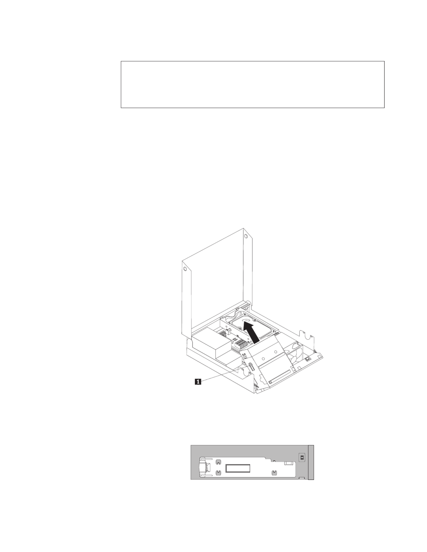
Replacing the hard disk drive
Attention
Do not open your computer or attempt any repair before reading and understanding the
“Important safety information” in the ThinkCentre Safety and Warranty Guide that came with
your computer. To obtain a copy of the ThinkCentre Safety and Warranty Guide, go to:
http://www.lenovo.com/support
This section provides instructions on how to replace the hard disk drive if your
computer has one. For computer models that do not have an internal hard disk
drive and use a remote hard disk drive accessed through the SMC - Storage Array,
contact your network or storage administrator.
Important
When you receive a new hard disk drive, you also receive a set of Product
Recovery discs Product Recovery discs. The set of enables you to restore the
contents of the hard disk drive to the factory default settings. For more
information on recovering factory-installed software, refer to Chapter 3,
“Recovery information,” on page 41.
To replace the hard disk drive:
1. Open the computer cover. See “Opening the computer cover” on page 14.
2. You might need to pivot the optical drive bay assembly upward to gain easy
access to the hard disk drive.
3. Locate the hard disk drive.
24 User Guide

4. Push the blue handle of the hard disk drive bracket inwards to release the two
clips that secure the hard disk drive to the chassis and then pivot the hard1
disk drive upwards.
5. Disconnect the signal cable and the power cable from the hard disk drive and
then lift the hard disk drive up to completely remove it from the chassis.
6. Remove the failing hard disk drive from the bracket by flexing the sides of the
bracket enough.
Figure 16. Removing the hard disk drive
Chapter 2. Installing options and replacing hardware 25

7. To install a new hard disk drive into the bracket, flex the bracket and align
pin , pin , pin , and pin on the bracket with the holes in the1 2 3 4
hard disk drive.
Important: Do not touch the circuit board on the bottom of the hard disk
drive.
8. Connect the signal cable and the power cable to the new hard disk drive.
9. Install the new hard disk drive and bracket into the hard disk drive retainer
and rotate down until the two clips on the blue handle of the hard disk drive
bracket snap into position.
10. Go to “Completing the parts replacement” on page 36.
Figure 17. Installing the hard disk drive bracket
26 User Guide
Replacing the optical drive
Attention
Do not open your computer or attempt any repair before reading and understanding the
“Important safety information” in the ThinkCentre Safety and Warranty Guide that came with
your computer. To obtain a copy of the ThinkCentre Safety and Warranty Guide, go to:
http://www.lenovo.com/support
This section provides instructions on how to replace the optical drive.
To replace the optical drive:
1. Open the computer cover. See “Opening the computer cover” on page 14.
2. Pivot the optical drive bay assembly upward to gain easy access to the optical
drive.
3. Disconnect the signal cable and the power cable from the rear of the optical
drive.
4. Press the optical drive lock and slide the optical drive out of the rear of the1
drive bay assembly.
5. Remove the optical drive retainer from the drive being replaced and then
install the retainer on the left side of the new drive to be installed.
Figure 18. Removing the old optical drive
Figure 19. Installing the retainer
Chapter 2. Installing options and replacing hardware 27
Produkt Specifikationer
| Mærke: | Lenovo |
| Kategori: | Skrivebord |
| Model: | ThinkCentre 7638 |
Har du brug for hjælp?
Hvis du har brug for hjælp til Lenovo ThinkCentre 7638 stil et spørgsmål nedenfor, og andre brugere vil svare dig
Skrivebord Lenovo Manualer

23 November 2024
23 November 2024
10 Oktober 2024
10 Oktober 2024
17 September 2024
10 September 2024
9 September 2024
31 August 2024
28 August 2024
13 August 2024
Skrivebord Manualer
- Skrivebord Ikea
- Skrivebord Acer
- Skrivebord Sony
- Skrivebord Samsung
- Skrivebord Panasonic
- Skrivebord Apple
- Skrivebord Sharp
- Skrivebord HP
- Skrivebord Asus
- Skrivebord Gigabyte
- Skrivebord Toshiba
- Skrivebord InFocus
- Skrivebord Asrock
- Skrivebord Butler
- Skrivebord Optoma
- Skrivebord Zaor
- Skrivebord JYSK
- Skrivebord Parisot
- Skrivebord United Office
- Skrivebord Razer
- Skrivebord Medion
- Skrivebord Haier
- Skrivebord Seagate
- Skrivebord Vtech
- Skrivebord Tripp Lite
- Skrivebord Packard Bell
- Skrivebord Microsoft
- Skrivebord Fellowes
- Skrivebord Digitus
- Skrivebord Genesis
- Skrivebord Techly
- Skrivebord Viewsonic
- Skrivebord Dell
- Skrivebord ELO
- Skrivebord Fujitsu
- Skrivebord Cooler Master
- Skrivebord MSI
- Skrivebord NEC
- Skrivebord Bush
- Skrivebord TrekStor
- Skrivebord ECS
- Skrivebord SPC
- Skrivebord ZTE
- Skrivebord Kobo
- Skrivebord Kramer
- Skrivebord Onyx
- Skrivebord Vorago
- Skrivebord EMachines
- Skrivebord Axis
- Skrivebord Faytech
- Skrivebord Intel
- Skrivebord Sharkoon
- Skrivebord Supermicro
- Skrivebord BDI
- Skrivebord Kogan
- Skrivebord LC-Power
- Skrivebord Planar
- Skrivebord Overdrive
- Skrivebord Zotac
- Skrivebord Moxa
- Skrivebord Alienware
- Skrivebord Aeris
- Skrivebord Maxdata
- Skrivebord Targa
- Skrivebord Peaq
- Skrivebord Shuttle
- Skrivebord Promethean
- Skrivebord Foxconn
- Skrivebord Ibm
- Skrivebord Advantech
- Skrivebord Pelco
- Skrivebord Xtech
- Skrivebord MP
- Skrivebord Elitegroup
- Skrivebord X Rocker
- Skrivebord Smart Things
- Skrivebord System76
- Skrivebord Zoostorm
- Skrivebord Bestar
- Skrivebord Cybernet
- Skrivebord Altra
- Skrivebord Dell Wyse
- Skrivebord AOpen
- Skrivebord ProDVX
- Skrivebord NComputing
- Skrivebord MvixUSA
- Skrivebord Seville Classics
- Skrivebord AIS
- Skrivebord Wyse
- Skrivebord Mount-It!
Nyeste Skrivebord Manualer

1 April 2025
4 Marts 2025

18 Februar 2025

15 Februar 2025
14 Februar 2025
14 Februar 2025
14 Februar 2025
14 Februar 2025

10 Januar 2025
6 Januar 2025