LevelOne FCS-3071 Manual
LevelOne
Overvågningskamera
FCS-3071
Læs nedenfor 📖 manual på dansk for LevelOne FCS-3071 (74 sider) i kategorien Overvågningskamera. Denne guide var nyttig for 29 personer og blev bedømt med 4.5 stjerner i gennemsnit af 2 brugere
Side 1/74

FCS-3071
2-Megapixel PoE Dome Network Camera
User Manual
Ver1.4

1
Table of Contents
1. Introduction.................................................................................................................3
1.1
Features ...................................................................................................................... 3
1.2
Package Contents ....................................................................................................... 4
1.3
Camera Overview........................................................................................................ 4
2. Preparations for IP Camera Setup ............................................................................6
2.1
System Requirements ................................................................................................. 6
3. Accessing Camera .....................................................................................................6
Using recording software....................................................................................................... 11
Installing DC Viewer Software Online.................................................................................... 12
4. Configuration & Operation.......................................................................................15
4.1
Browser-based Viewer Introduction ........................................................................... 15
4.2
Home Page................................................................................................................ 17
4.3
System Related Settings............................................................................................ 19
4.3.1
Host Name and System Time Setting......................................................... 20
4.3.2
Security ...................................................................................................... 21
4.3.3
Network...................................................................................................... 24
4.3.4
DDNS......................................................................................................... 29
4.3.5
Mail ............................................................................................................ 30
4.3.6
FTP ............................................................................................................ 31
4.3.7
Motion Detection ........................................................................................ 32
4.3.8
Storage Management................................................................................. 36
4.3.9
Recording................................................................................................... 38
4.3.10
File Location............................................................................................... 39
4.3.11
View Log File.............................................................................................. 40
4.3.12
View User Information ................................................................................ 41
4.3.13
View Parameters........................................................................................ 43
4.3.14
Factory Default........................................................................................... 44
4.3.15
Software Version........................................................................................ 45
4.3.16
Software Upgrade ...................................................................................... 46
4.3.17
Maintenance............................................................................................... 49
4.4
Video Streaming Settings .......................................................................................... 50
4.4.1
Video Resolution and Rotate Type ............................................................. 50
4.4.2
Video Compression .................................................................................... 53
4.4.3
Video OCX Protocol ................................................................................... 55
4.4.4
Video Frame Skip....................................................................................... 56
4.4.5
Video Mask ................................................................................................ 57
4.5
Camera Settings........................................................................................................ 58
4.5.1
Exposure Setting........................................................................................ 58

2
4.5.2
White Balance Setting ................................................................................ 60
4.5.3
Brightness Setting ...................................................................................... 61
4.5.4
Sharpness Setting ...................................................................................... 61
4.5.5
Contrast Setting ......................................................................................... 61
4.5.6
Saturation Setting....................................................................................... 61
4.5.7
Hue Setting ................................................................................................ 62
4.5.8
TV System Setup ....................................................................................... 62
4.6
Logout ....................................................................................................................... 63
Appendix A: Technical Specifications...........................................................................64
Appendix B: Internet Security Settings .........................................................................66
Appendix C: DC Viewer Download Procedure ..............................................................69
Appendix D: Install UPnP Components.........................................................................71
Default ID / Password
Login ID Password
root null(without password)

3
1. Introduction
The LevelOne FCS-3071 is a compact, rugged H.264 2-Megapixel PoE Mini
Dome Camera designed for tough environments. The casing is tamper-resistant,
it can withstand vibration, humidity, dust and fluctuating temperatures found. for
example buses and trains.
The FCS-3071 is a palm-sized, discreet network camera specifically designed
for mass transit vehicles. The flat tamper-resistant casing makes it ideal for
installation. The IP66 rating provides a rugged package for both indoor and
outdoor applications
In compatible with EN50155, the standard for electronic equipment operating in
railway vehicles, the FCS-3071 is an economical mobile surveillance solution
with high reliability and rugged performance.
The FCS-3071 utilizes PoE (Power-over-Ethernet), allowing it to be operated
and powered from a single Ethernet cable, giving greater ease of installation
and cost savings. In order to facilitate on-board storage and data portability, the
FCS-3071 is also complete with a Micro SD/SDHC card slot for local recording.
1.1 Features
- 2-Megapixel Progressive Scan CMOS Sensor
- Dual streaming simultaneously
- H.264 and MJPEG Compression
- Shockproof for Rolling Stock Applications
- Weatherproof IP66 housing & RJ-45 dongle cable
- Micro SD/SDHC Card Slot for On-Board Storage
- Powered by PoE (802.3af) Only
- Free software included (Industry-leading 64-channel IP CamSecure™ software)

4
1.2 Package Contents
Please check the package contains the following items listed below.
Indoor Camera/
Rugged Camera (with Cable)
Self-tapping
screws ( 3) ×
Plastic Anchors
( 3)×
Security Screw
( 1) ×
Rubber Washer ( 1, Casing) ×
Rubber Washers ( 3, Baseplate)×
(Rugged Camera only)
Security Torx
Quick Guide
CD
1.3 Camera Overview
Designation Description
1
Reset Button Restore to default setting; press the
button with a proper tool
2
Lens Rotate the lens right/left to adjust focus
3
Focus Fixed Screw
Loosen the screw to adjust the lens
4
Tilt Fixed Screw Loosen the screw to adjust tilt angle
5
Micro SD Card Slot
Micro SD Card recording
5
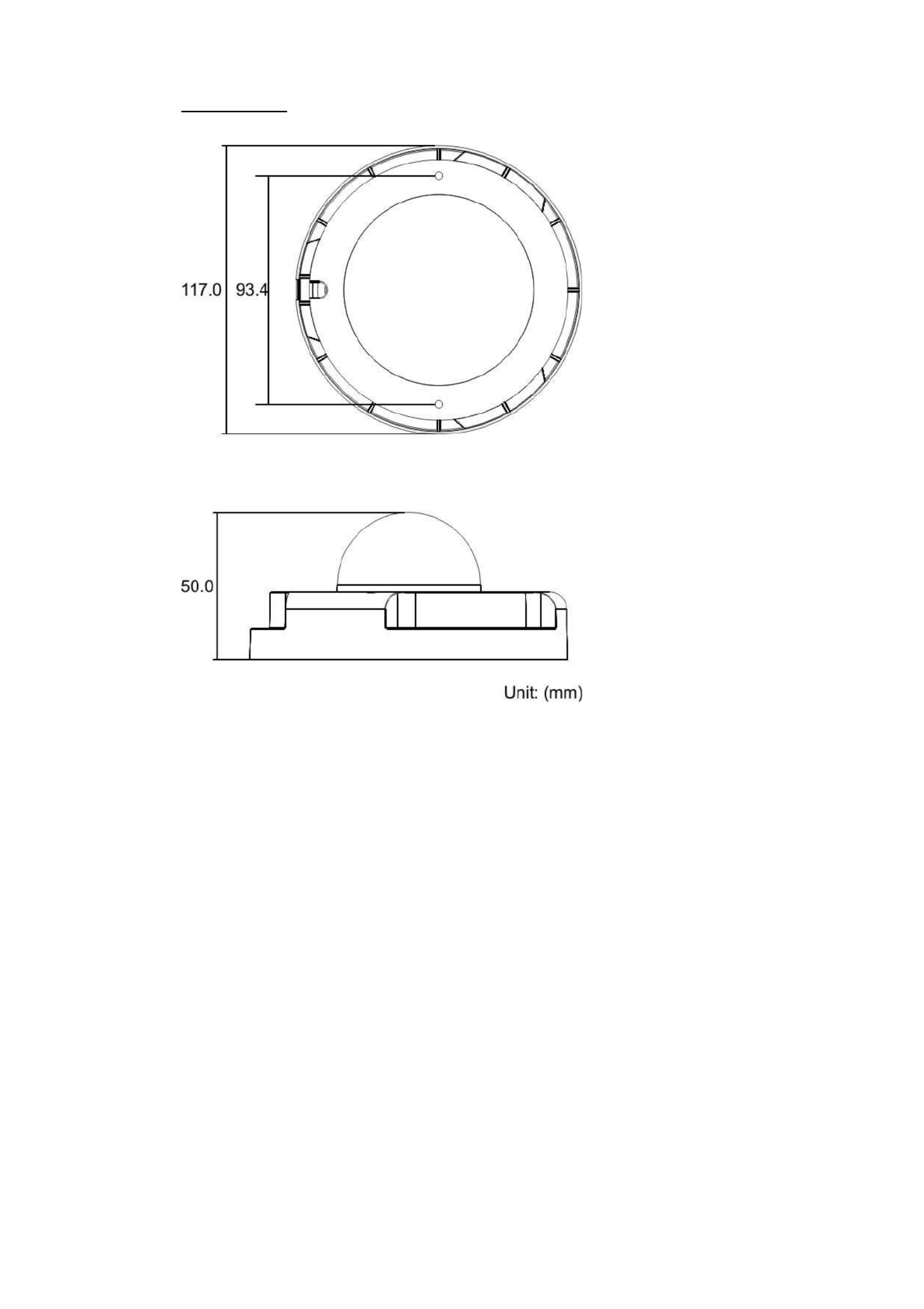
Dimensions

6
2. Preparations for IP Camera Setup
This chapter provides information about system requirements for IP Dome
Camera operation, power and Ethernet connection for Indoor/Outdoor IP Dome
Camera and ways to access to the camera.
2.1 System Requirements
To perform the IP Camera via web browser, please ensure your PC is in good
network connection, and meet system requirements as described below.
Items System Requirement
Personal Computer
1. Intel○
R Pentium○
R M, 2.16 GHz or Intel○
R Core
TM
2 Duo,
2.0 GHz
2. 2 GB RAM or more
Operating System Windows VISTA or Windows XP
Web Browser Microsoft Internet Explorer 6.0 or later
Network Card 10Base-T (10 Mbps) or 100Base-TX (100 Mbps) operation
Viewer ActiveX control plug-in for Microsoft IE
3. Accessing Camera
For initial access to the IP Camera, users can search the camera through the
installer program: DeviceSearch.exe, which can be found in “Device Search”
folder in the supplied CD.
Device Search Software Setup
Step 1: Double click on the program Device Search.exe (see the icon below);
its window will appear as shown below. Then click the “Device Search”
button.

7
Step 2: The security alert window will pop up. Click “Unblock” to continue.
Device Search
Step 3: Click “Device Search” again, and all the finding IP devices will be listed
in the page, as shown in the figure below. The IP Camera’s default IP
address is: . 192.168.0.250
Step 4: Double click or right click and select “Browse” to access the camera
directly via web browser.

8
Step 5: Then the prompt window of request for entering default username
and password (as shown below) will appear for logging in to the IP
Dome Camera.
The default login ID and password are:
Login ID Password
root null(without password)
NOTE: ID and password are case sensitive.
NOTE: It is strongly advised that administrator’s password be
altered for the security concerns. Refer to section 5.3.2 Security
for further details.
Additionally, users can change the IP Camera’s network property, either DHCP
or Static IP, directly in the device finding list. Refer to the following section for
changing the IP Camera’s network property.
9
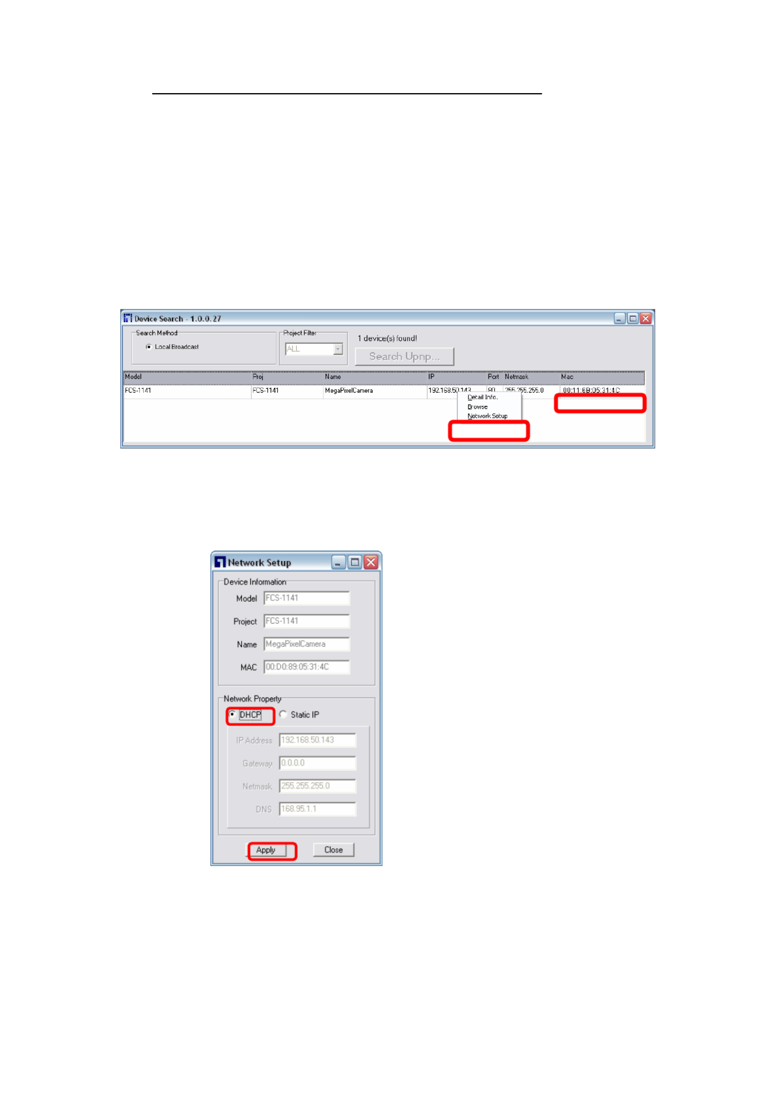
Example of Changing IP Camera’s Network Property
Users can directly change an IP Camera’s network property, ex. from static IP
to DHCP, in the finding device list. The way to change the IP Camera’s network
property is specified below:
Step 1: In the finding device list, click on the IP Camera that you would like to
change its network property. On the selected item, right click and select
“Network Setup.” Meanwhile, record the IP Camera’s MAC address, for
future identification.
Step 2: The “Network Setup” page will come out. Select “DHCP,” and press
“Apply” button down the page.
Step 3: Click “OK” on the Note of setting change. Wait for one minute to
re-search the IP Camera.

10
Step 4: Click the “Device Search” button to search all the devices. Then select
the IP Camera with the correct MAC address. Double click on the IP
Camera, and the login window will come out.
Step 5: Enter User name and Password to access the IP Camera.

11
Using recording software
The product software CD also contains recording software-IP CamSecure, allowing
simultaneous monitoring and video recording for multiple Network Cameras Please install .
the recording software; then launch the program to add the Network Camera to the
Channel list For detailed information about how to use IP CamSecure, please refer to the .
user’s manual of the software or download it at http://global.level1.com.

13
Once login to the IP Camera, users will see the Home page as shown below:
Administrator/User Privileges
“Administrator” represents the person who can configure the IP Camera and
authorize user’s access to the camera; “User” refers to whoever has access to
the camera with limited authority, i.e. entering Home and Camera setting pages.
Image and Focus Adjustment
The image displays on the Home page when successfully accessing to the IP
Camera. Adjust zoom and focus as necessary to produce a clear image.
Step 1: Unscrew the IP Dome Camera’s cover.

14
Step 2: Loosen the focus fixed screw, and rotate the lens counter-/clockwise to
adjust focus; loosen the tilt fixed screw, and adjust the camera’s tilt
angle.

15
4. Configuration & Operation
The IP Camera is provided with a user-friendly browser-based configuration
interface, as well as a free bundled CMS (Central Management System) for
video playback and recording. In this chapter, information about main page
introduction, system related settings and camera settings will be described in
detail.
For further information about CMS software, please refer to IP CamSecure user
manual.
4.1 Browser-based Viewer Introduction
The figure below shows the Home page of the IP Camera’s Viewer Window.
NOTE: Please note that the function buttons will vary depending on the
camera model.
Time Display
Live Video Panel
Recording Button
Video Compression Info
Video Stream Pause Button
Snapshot Button
Display Mode

16
There are five tabs: Home, System, Streaming, Camera and Logout on the top
of the viewer window.
Home
Users can monitor live video of the targeted area.
System setting
The administrator can set host name, system time, root password, network
related settings, etc. Further details will be interpreted in section “System
Related Settings”.
Streaming setting
The administrator can modify video resolution and rotate type in this page.
Camera setting
Users can adjust various camera parameters, including <Exposure>, <White
Balance>, <Brightness>, <Sharpness>, <Contrast> and <Digital Zoom>.
Logout
Click on the tab to re-login the IP Camera with another username and
password.

17
4.2 Home Page
In the Home page, there are several function buttons right down the displayed
image.
NOTE: Please note that the function buttons will vary depending on the
camera model.
Screen Size Adjustment
Image display size can be adjusted to x1/2 and full screen.
Digital Zoom Control
In the full screen mode, users can implement digital PTZ by rotating the mouse
wheel (for zoom in/out), and drag the mouse into any direction.
Snapshot button
Press the button, and the JPEG snapshots will automatically be saved in the
appointed place. The default place of saving snapshots is: C:\. To change the
storage location, please refer to section “File Location” for further details.

19
4.3 System Related Settings
The figure below shows all categories under the “System” tab. Each category in
the left column will be explained in the following sections.
NOTE: The “System” configuration page is only accessible by the
Administrator.
20
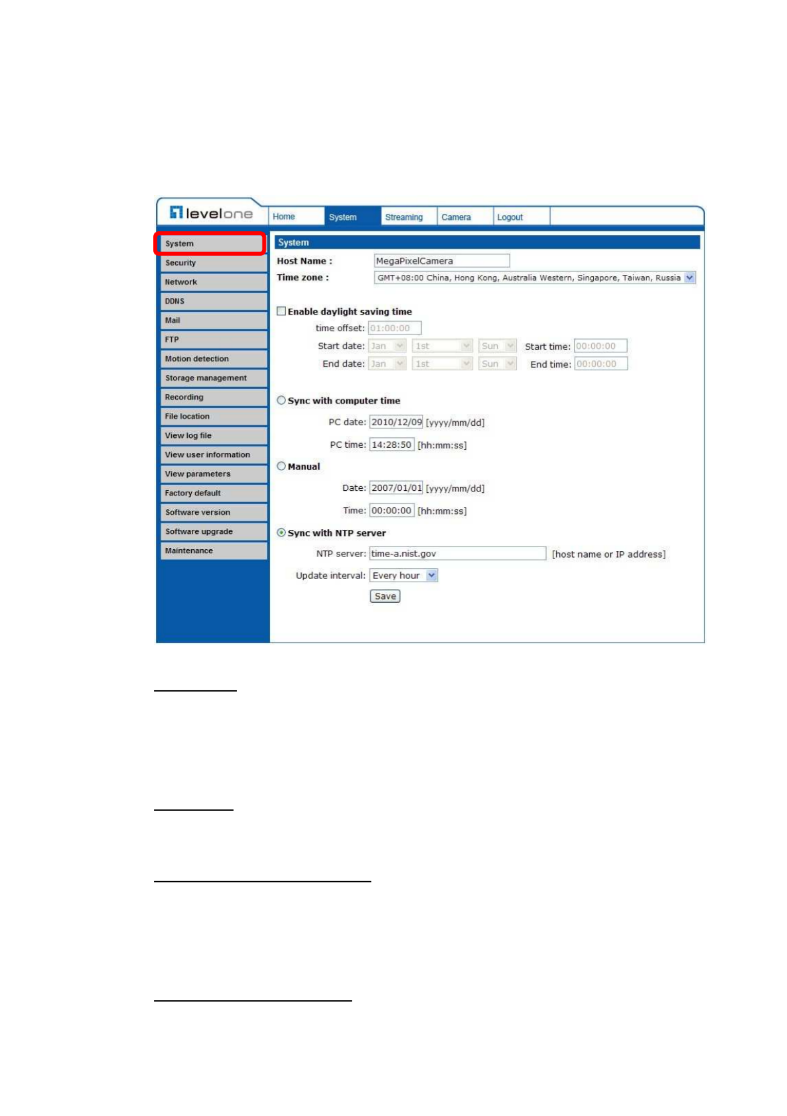
4.3.1 Host Name and System Time Setting
Press the first category: <System> in the left column; the page is shown as
below.
Host Name
The name is for camera identification. If alarm function is enabled and is set to
send alarm message by Mail/FTP, the host name entered here will display in
the alarm message.
Time Zone
Select the time zone you are in from the drop-down menu.
Enable Daylight Saving Time
To enable DST, please check the item and then specify time offset and DST
duration. The format for time offset is [hh:mm:ss]; for instance, if the amount of
time offset is one hour, please enter “01:00:00” into the field.
Sync With Computer Time
Select the item, and video date and time display will synchronize with the PC’s.

21
Manual
The Administrator can set video date, time and day manually. Entry format
should be identical with that shown next to the enter fields.
Sync with NTP server
Network Time Protocol (NTP) is an alternate way to synchronize your camera’s
clock with a NTP server. Please specify the server you wish to synchronize in
the enter field. Then select an update interval from the drop-down menu. For
further information about NTP, please see the web site: . www.ntp.org
4.3.2 Security
Click the category: <Security>, and the page is shown as the figure below.
Root password
Change the administrator’s password by inputting the new password in both text
boxes. The input characters/numbers will be displayed as dots for security
purposes. After clicking <Save>, the web browser will ask the Administrator for
the new password for access. The maximum length of the password is 14 digits.

22
NOTE: The following characters are valid: A-Z, a-z, 0-9, !#$%&’-.@^_~.
Add user
Type the new user's name and password and click <Add> to add the new user.
Both user name and password can be up to 16 characters. The new user will be
displayed in the user name list. There is a maximum of twenty user accounts.
Each user can be assigned the privileges of and/or “Camera control”
“Listen”.
• I/O access
This item supports fundamental functions that enable users to view
video when accessing to the camera.
• Camera control
This item allows the appointed User to change camera parameters on
the Camera Setting page.
• Talk/Listen
Talk and Listen functions allow the appointed user in the local site (PC
site) communicating with, for instance, the administrator in the remote
site.
NOTE: The Compact IP Dome Camera does not have the Talk
function.
Manage User
Delete user
To delete a user, pull down the user list, and select the user name you wish to
delete. Then click <Delete> to remove it.
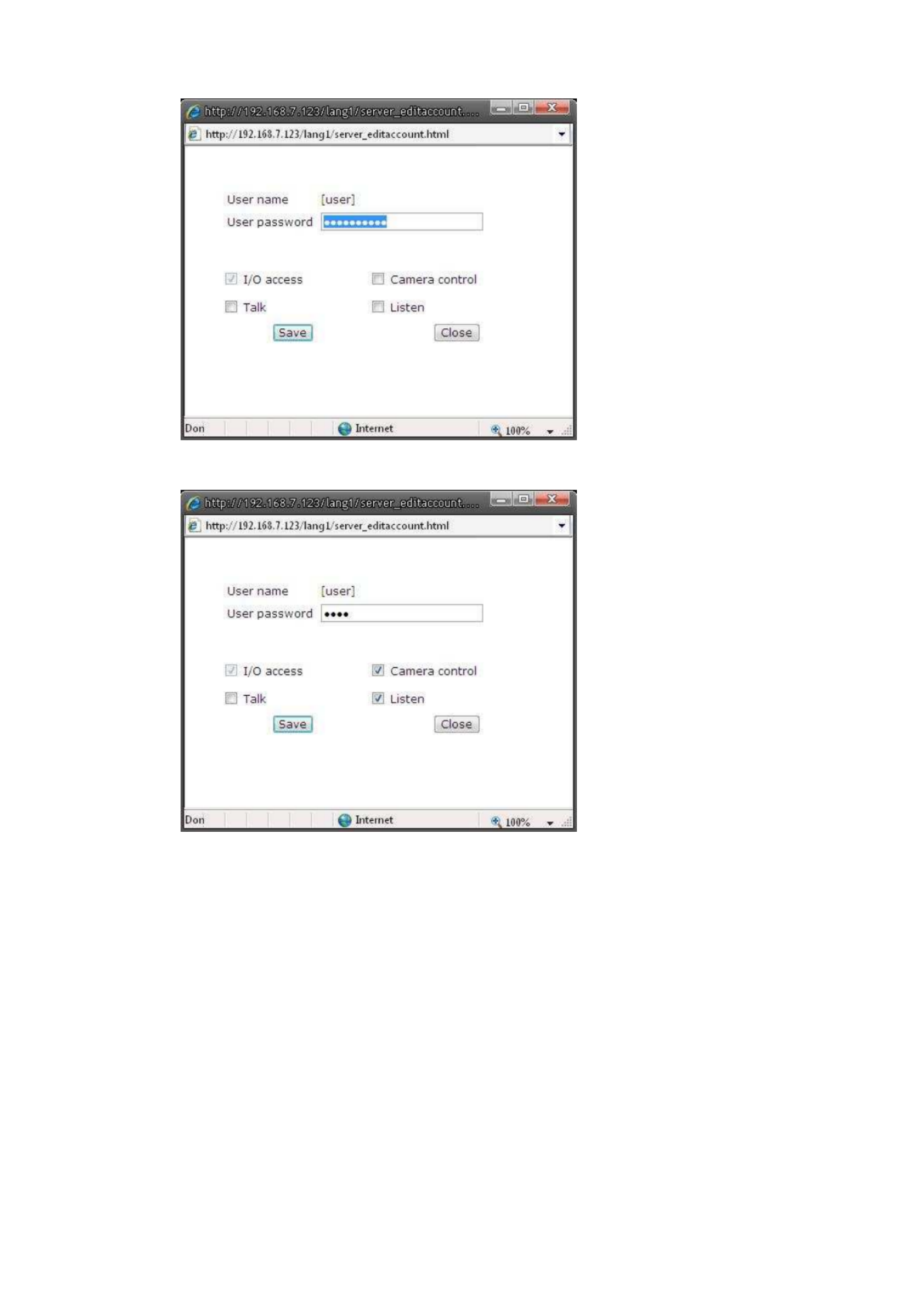
Edit user
Pull down the user list and select a user name. Click <Edit> to edit the user’s
password and privilege.
NOTE: It is required to enter the User password as well as select the
function open to the user. When finished, click <Save> to modify the
account authority.
23

24
4.3.3 Network
Click <Network> in the left column, and the page will display as shown below.
Users can choose to connect to the IP Camera with fixed or dynamic (DHCP) IP
address. The IP Camera also provides PPPoE support for users who connect to
the network via PPP over Ethernet (PPPoE).
Get IP address automatically (DHCP)
The camera’s default setting is “Use fixed IP address”. Please refer to the
previous section “ for logging in with the default IP address. Accessing Camera”
If select “ ”, after the IP Camera restarts, users Get IP address automatically
can search it through the installer program: Device Search.exe, which can be
found in “Device Search” folder in the supplied CD.
NOTE: Please make the record of the IP Camera’s MAC address, which
can be found in the label of the camera, for identification in the future.

26
• Default gateway
This is the gateway used to forward frames to destinations in different
subnet. Invalid gateway setting will fail the transmission to destinations
in different subnet.
• Primary DNS
Primary DNS is the primary domain name server that translates
hostnames into IP addresses.
• Secondary DNS
Secondary DNS is a secondary domain name server that backups the
primary DNS.
Use PPPoE
For the PPPoE users, enter the PPPoE Username and Password into the fields,
and click on the “Save” button to complete the setting.
Advanced
• Web Server port
The default web server port is 80. Once the port is changed, the user
must be notified the change for the connection to be successful. For
instance, when the Administrator changes the HTTP port of the IP
Camera whose IP address is 192.168.0.100 from 80 to 8080, the user
must type in the web browser “http://192.168.0.100:8080” instead of
http://192.168.0.100.
• RTSP port
RTSP port could be set from 1 to 65535. (Normal Setting Port: 554,
1024 ~65535)
• MJPEG over HTTP port
The default setting of HTTP Port is 8008; setting range: 1024 ~65535.
NOTE: Be aware to choose the different port from the one set for the
web server port.
27
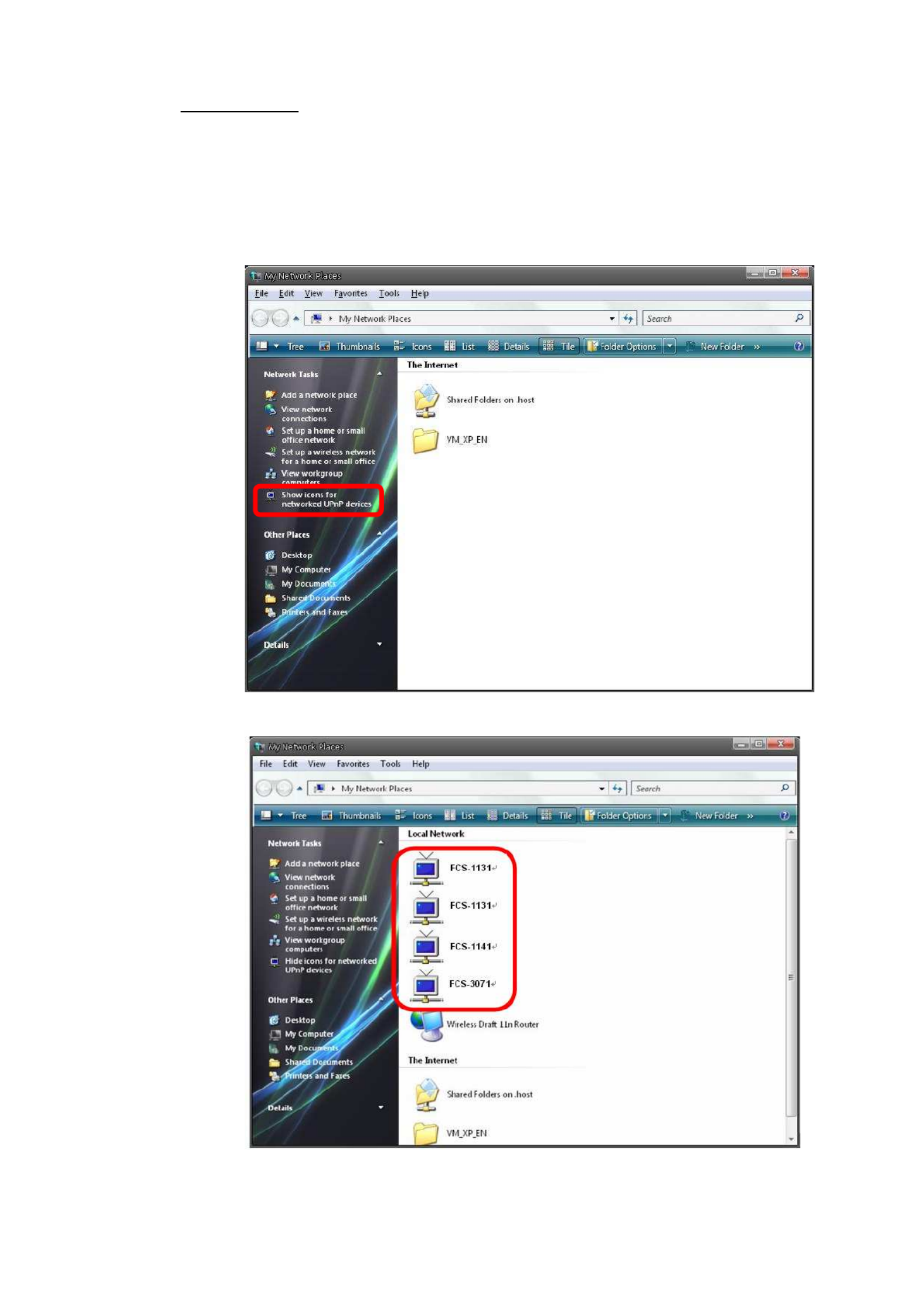
UPnP Setting
• Enable UPnP
When the UPnP is enable, whenever the IP Camera is presented to the
LAN, the icon of the connected IP Cameras will appear in My Network
Places to allow for direct access as shown below.

29
4.3.4 DDNS
Dynamic Domain Name System (DDNS) allows a host name to be constantly
synchronized with a dynamic IP address. In other words, it allows those using a
dynamic IP address to be associated to a static domain name so others can
connect to it by name.
Enable DDNS
Check the item to enable DDNS.
Provider
Select one DDNS host from the provider list.
Host name
Enter the registered domain name in the field.
Username/E-mail
Enter the username or e-mail required by the DDNS provider for authentication.
30
Password/Key
Enter the password or key required by the DDNS provider for authentication.
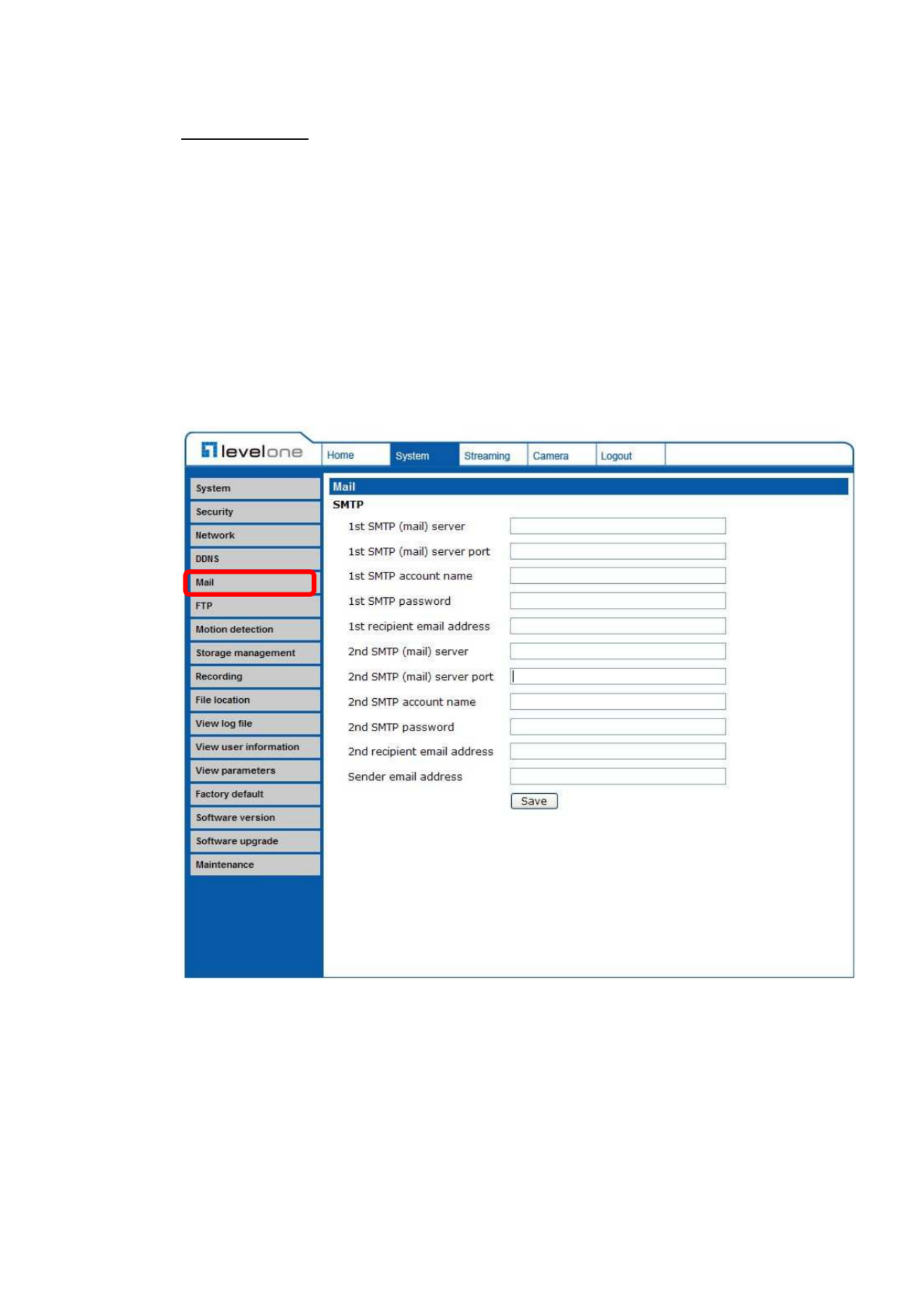
4.3.5 Mail
The Administrator can send an e-mail via Simple Mail Transfer Protocol (SMTP)
when motion is detected. SMTP is a protocol for sending e-mail messages
between servers. SMTP is a relatively simple, text-based protocol, where one or
more recipients of a message are specified and the message text is transferred.
The configuration page is shown as follows:
Two sets of SMTP can be configured. Each set includes SMTP Server, Account
Name, Password and E-mail Address settings. For SMTP server, contact your
network service provider for more specific information.

31
4.3.6 FTP
The Administrator can set as sending alarm message to a specific File Transfer
Protocol (FTP) site when motion is detected. Users can assign alarm message
to up to two FTP sites. The FTP setting page is shown below. Enter the FTP
details, which include server, server port, user name, password and remote
folder, in the fields. Press “Save” when finished.

33
If Motion Detection function is activated, the pop-off window (Motion) with
indication of motion will be shown.
When motion is detected, the signals will be displayed on the Motion window as
shown below.
Detailed settings of Motion Detection are described as follows:
Motion Detection
You will be able to turn on/off Motion Detection in System section. Default
setting is Off.
Motion Detection Setting
Users could adjust various parameters of Motion Detection in this section.
• Sampling pixel interval [1-100]:
The default value is 10, which means system will take one sampling
pixel for every 10 pixel.
• Detection level [1-100]:
The default level is 10. The item is to set detection level for each
sampling pixel; the smaller the value, the more sensitive it is.

34
• Sensitivity level [1-100]:
The default level is 80, which means if 20% or more sampling pixels are
detected differently, system will detect motion. The bigger the value, the
more sensitive it is. Meanwhile, when the value is bigger, the red
horizontal line in the motion indication window will be lower accordingly.
• Time interval (sec) [0-7200]:
The default interval is 10. The value is the interval between each
detected motion.
Triggered Action (Multi-option)
The Administrator can specify alarm actions that will take when motion is
detected. All options are listed as follows:
• Enable Alarm Output
Check the item and select the predefined type of alarm output to enable
alarm relay output when motion is detected.
NOTE: This option is excluded in the Compact IP Dome
Camera.
• Record stream to SD Card
Select this item, and the Motion Detection recording will be stored in
Micro SD/ SDHC card when motion is detected.
NOTE: Please make sure the local recording (with Micro SD/
SDHC card) is activated so that this function can be implemp-
lemented. See section for further details. “Recording”
• Send Alarm Message by FTP/E-Mail
The Administrator can select whether to send an alarm message by
FTP and/or E-Mail when motion is detected.
• Upload Image by FTP
Select this item, and the Administrator can assign a FTP site and
configure various parameters as shown in the figure below. When
motion is detected, event images will be uploaded to the appointed FTP
site.

35
• Upload Image by E-Mail
Select this item, and the Administrator can assign an e-mail address
and configure various parameters as shown in the figure below. When
motion is detected, event images will be sent to the appointed e-mail
address.
NOTE: Make sure SMTP or FTP configuration has been completed. See
section “ for further details. Mail” and “FTP”
File Name
The uploaded image’s filename format can be set in this section. Please select
the one that meets your requirements.
Save
Click the Save button to save all the Motion Detection settings mentioned
above.
36
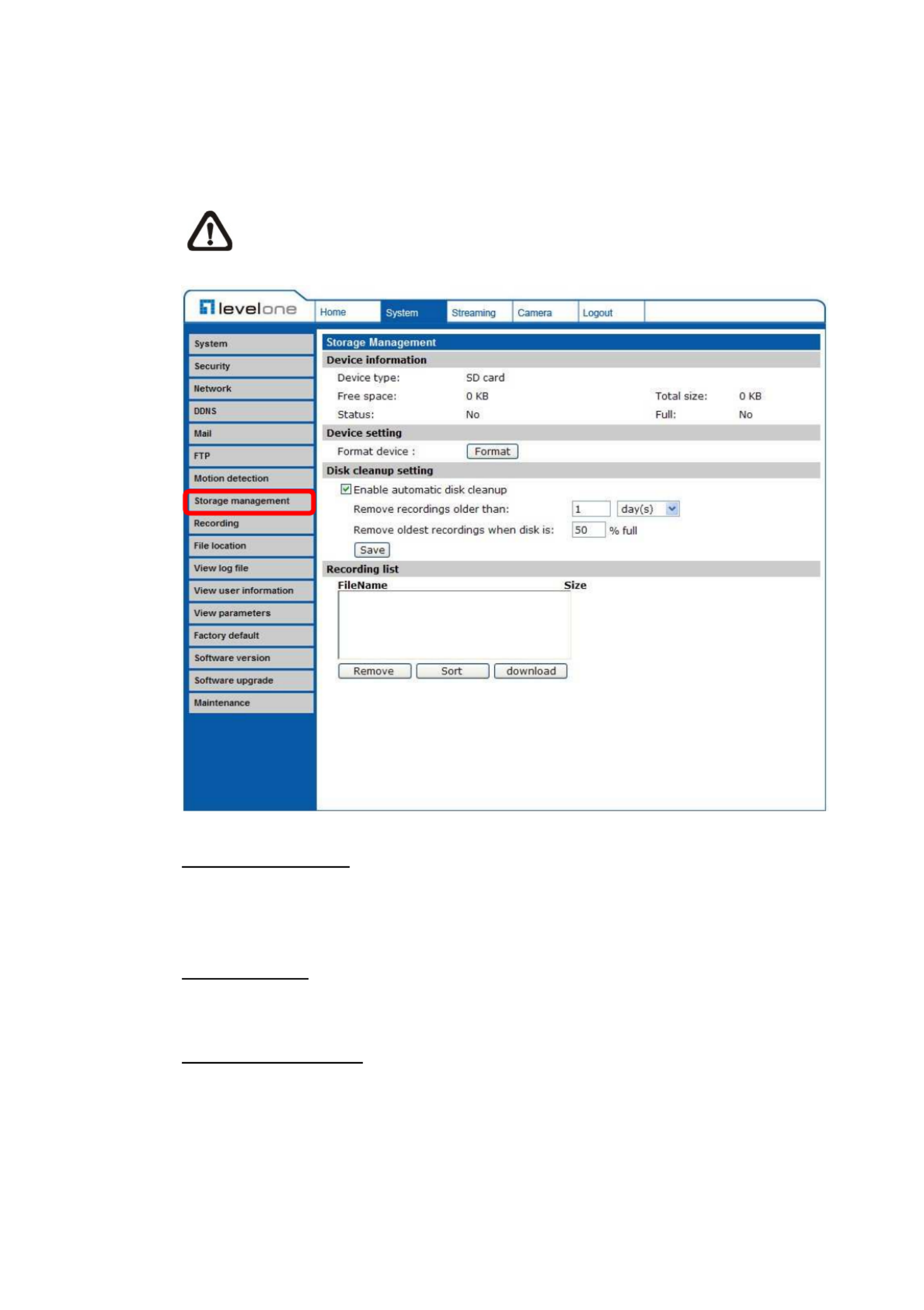
4.3.8 Storage Management
Users can implement local recording to the Micro SD/SDHC card.
NOTE: Please format the Micro SD/SDHC card first before recording
starts.
Device information
When users insert the Micro SD/SDHC card, the card information such as the
memory capacity and status will be shown at Device Information section.
Device setting
Press the “Format” button to format the memory card.
Disk cleanup setting
Users can enable automatic recordings cleanup by specifying the time and
storage limits
37
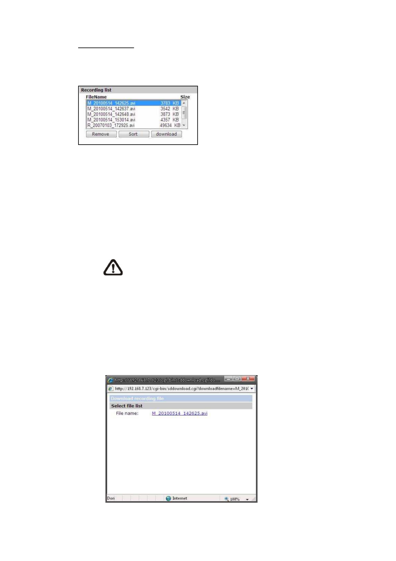
Recording List
Each video file on the Micro SD/SDHC card will be listed in the Recording list as
shown below.
• Remove
To remove a file, select the file first, and then press the “Remove”
button.
• Sort:
Press the “Sort” button, and the files in the Recording list will be listed in
name and date order.
NOTE: The capital letter A/M/R appears in the very beginning of
name denotes the sort of the recording: A stands for Alarm; M
stands for Motion; R stands for regular recording.
• Download:
To open/download a video clip, select the file first, and then press the
“download” button below the Recording list field. The selected file
window will pop up as shown below. Click on the AVI file to directly play
the video in the player or download it to a specified location.
38
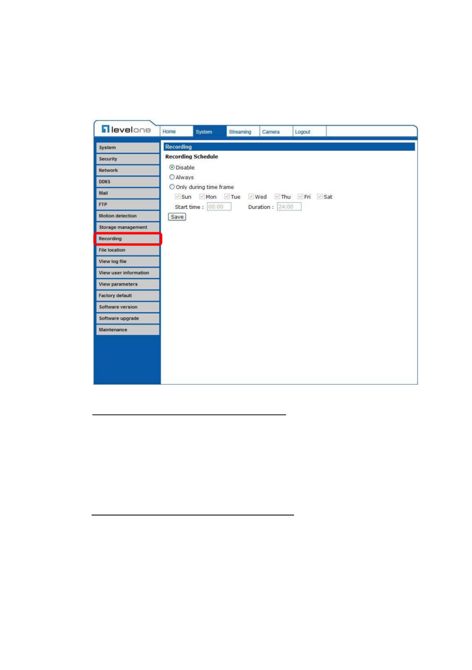
4.3.9 Recording
In the Recording setting page, users can specify the recording schedule that fits
the present surveillance requirement.
Activating Micro SD/SDHC Card Recording
Two types of schedule mode are offered: Always and Time Frame setting.
Users can setup the time frame to fit the recording schedule or choose “Always”
to activate Micro SD/SDHC Card Recording all the time.
Please click on the “Save” button for confirming the schedule mode.
Terminating Micro SD/SDHC Card Recording
Select “Disable” to terminate the recording function.
39
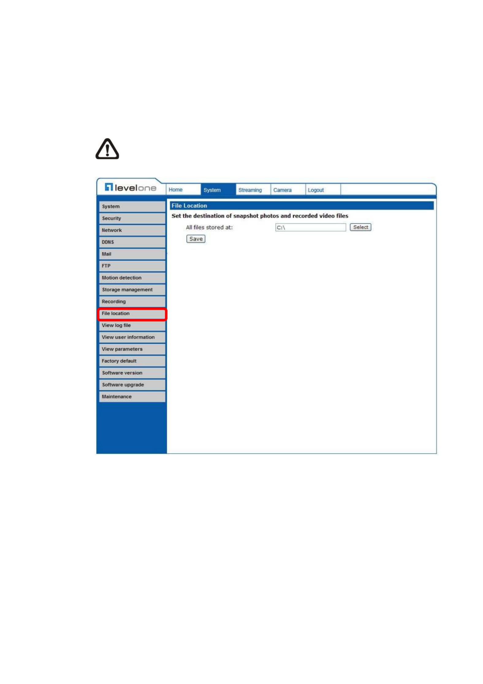
4.3.10 File Location
Users can specify a storage location for the snapshots and live video recording.
The default setting is: C:\. Once confirm the setting, press “Save,” and all the
snapshots and recording will be saved in the designate location.
NOTE: Please make sure the selected file path contains valid characters
such as letters and numbers.

40
4.3.11 View Log File
Click on the link to view the system log file. The content of the file provides
useful information about configuration and connections after system boot-up.
42
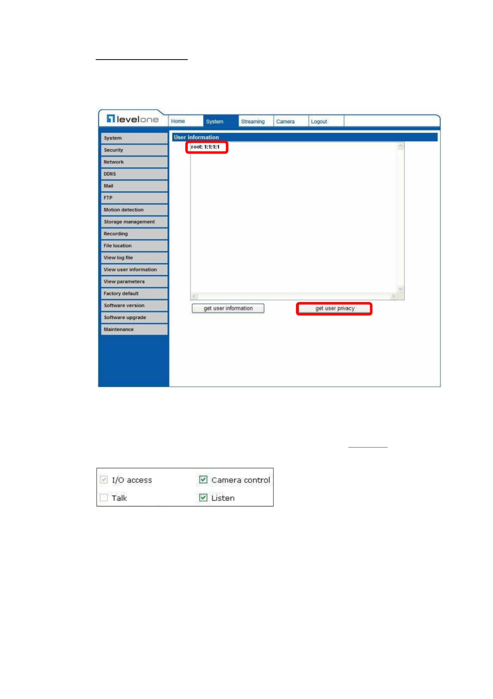
View User Privilege
Press “get user privacy” down the page, and the Administrator can view each
user’s privileges.
As the figure above shows:
User: 1:1:0:1
1:1:0:1= I/O access : Camera control : Talk : Listen (see “ ) Security”
Therefore, it denotes the user is granted privileges of I/O access, Camera
control and Listen.

43
4.3.13 View Parameters
Click on this item to view the entire system’s parameter setting.

44
4.3.14 Factory Default
The factory default setting page is shown as below. Follow the instructions to
reset the IP Camera to factory default setting if needed.
Set Default
Click on the “Set Default” button to recall the factory default settings. Then the
system will restart in 30 seconds.
NOTE: The IP address will be restored to default.
Reboot
Click on the “Reboot” button, and the system will restart without changing
current settings.

45
4.3.15 Software Version
The current software version is displayed in the software version page, which is
shown as the figure below.

46
4.3.16 Software Upgrade
Software upgrade can be carried out in the “Software Upgrade” page, as shown
below.
NOTE: Make sure the upgrade software file is available before carrying
out software upgrade.
The procedure of software upgrade is like the following:

47
Step 1: Click “Browse” and select the binary file to be uploaded, ex.
Userland.jffs2.
NOTE: Do not change the upgrade file name, or the system will fail to
find the file.
Step 2: Pull down the upgrade binary file list and select the file you want to
upgrade; in this case, select “userland.jffs2.”
Step 3: Press “Upgrade”. The system will first check whether the upgrade file
exists or not, and then begin to upload the upgrade file. Subsequently,
the upgrade status bar will display on the page. When it runs to 100%,
the upgrade process is finished.
49
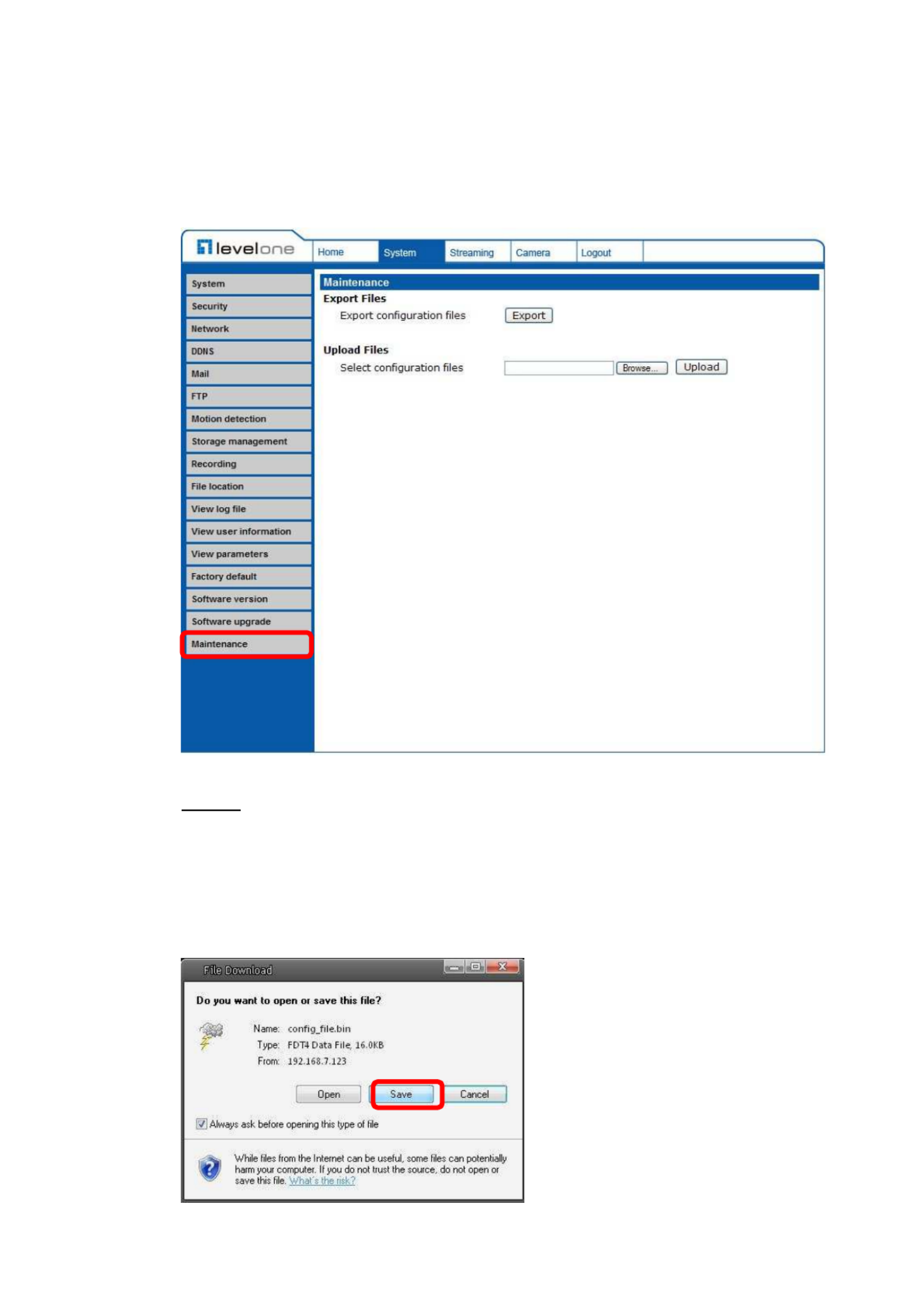
4.3.17 Maintenance
Users can export configuration files to a specified location and retrieve data by
uploading an existing configuration file to the IP Camera.
Export
Users can save the system settings by exporting the configuration file (.bin) to a
specified location for future use. Press the “Export” button, and the popup File
Download window will come out as shown below. Click “Save” and specify a
desired location for saving the configuration file.

50
Upload
To copy an existing configuration file to the IP Camera, please first click on
“Browse” to select the configuration file, and then press the “Upload” button for
uploading.
4.4 Video Streaming Settings
Press the tab ”Streaming” in the top of the page, and the configurable video
items will display in the left column. In Streaming, the Administrator can
configure specific video resolution, video compression mode, video protocol,
etc. Further details of these settings will be specified in the following sections.
4.4.1 Video Resolution and Rotate Type
The video setting page is shown below:
Produkt Specifikationer
| Mærke: | LevelOne |
| Kategori: | Overvågningskamera |
| Model: | FCS-3071 |
| Kode for international beskyttelse (IP): | IP66 |
| Type: | IP-sikkerhedskamera |
| Højde: | 50 mm |
| Vægt: | 180 g |
| Brugervejledning: | Ja |
| Produktfarve: | Black,White |
| Pakkevægt: | 500 g |
| Pakkedybde: | 80 mm |
| Pakkebredde: | 210 mm |
| Pakkehøjde: | 220 mm |
| Kompatible hukommelseskort: | MicroSD (TransFlash),MicroSDHC |
| Wi-Fi: | Ingen |
| Formfaktor: | Kuppel |
| Understøttede videotilstande: | 480p,720p,1080p |
| Relativ luftfugtighed ved drift (H-H): | 10 - 90 % |
| Ethernet LAN-porte (RJ-45): | 1 |
| Ethernet LAN: | Ja |
| Driftstemperatur (T-T): | -10 - 50 °C |
| Maksimal opløsning: | 1920 x 1080 pixel |
| Hurtig installationsvejledning: | Ja |
| Understøttede grafikopløsninger: | 352 x 288,640 x 480 (VGA),704 x 480,800 x 600 (SVGA),1024 x 768 (XGA),1280 x 1024 (SXGA),1280 x 720 (HD 720),1920 x 1080 (HD 1080) |
| Forbindelsesteknologi: | Ledningsført |
| Certificering: | CE, FCC |
| Strømforbrug (maks.): | 3.5 W |
| Netværksstandarder: | IEEE 802.1x,IEEE 802.3af |
| Understøttede netværksprotokoller: | IPv4/v6, TCP/IP, UDP, RTP, RTSP, HTTP, HTTPS, ICMP, FTP, SMTP, DHCP, PPPoE, UPnP, IGMP, SNMP, QoS, ONVIF |
| Knap til nulstilling: | Ja |
| IP-adresse filtrering: | Ja |
| Strømkilde type: | PoE |
| Diameter: | 117 mm |
| Indbygget kortlæser: | Ja |
| Full HD: | Ja |
| Indbygget HDD: | Ingen |
| Video komprimeringsformater: | H.264,M-JPEG |
| Understøttet placering: | Udendørs |
| Hvidbalance: | Automatisk |
| Sensortype: | CMOS |
| Samlet antal megapixels: | 2 MP |
| Støjreduktion: | Ja |
| Optisk zoom: | - x |
| Digital zoom: | 8 x |
| Fokusindstilling: | 1.5 |
| Grænseflade: | RJ-45 |
| Progressiv scanning: | Ja |
| Strøm over Ethernet (PoE): | Ja |
| Bredt dynamikområde (WDR): | Ja |
| Vandafvisende: | Ja |
| Minimumsbelysning: | 0.02 Lux |
| Optisk sensorstørrelse: | 1/2.7 " |
| Zoom kapacitet: | Ja |
| Fast brændvidde: | 4 mm |
| Nattesyn: | Ingen |
| Billedhastighed: | 30 fps |
| Justering af billedkvalitet: | Brightness,Contrast,Saturation,Sharpness |
| Fortrolighedspolitik maskering: | Ja |
| Tidsstempel overlay: | Ja |
| Tekst billedtekst overlay: | Ja |
| Ethernet-grænsefladetype: | Hurtigt ethernet |
| HTTPS -kryptering: | Ja |
| Kameraets lukkerhastighed: | 1 - 1/10000 sek./side |
| Kamera lukker type: | Elektronisk |
| PTZ-kontrol: | Ja |
| Automatisk forstærkningskontrol: | Ja |
| Adgangskodebeskyttelse type: | Bruger |
| Flip & spejl: | Ja |
| Aktiv manipulering af alarm: | Ja |
| Objektivets synsvinkel, vandret: | 78 ° |
| Portrættilstand: | Ja |
| Antal videostreams: | 4 |
| Kompensationsmetode for baglys: | Ja |
Har du brug for hjælp?
Hvis du har brug for hjælp til LevelOne FCS-3071 stil et spørgsmål nedenfor, og andre brugere vil svare dig
Overvågningskamera LevelOne Manualer

23 September 2024
14 September 2024
20 August 2024
16 August 2024
10 August 2024
6 August 2024
6 August 2024
4 August 2024
4 August 2024
4 August 2024
Overvågningskamera Manualer
- Overvågningskamera Bosch
- Overvågningskamera Denver
- Overvågningskamera Sony
- Overvågningskamera Canon
- Overvågningskamera Netis
- Overvågningskamera Samsung
- Overvågningskamera Panasonic
- Overvågningskamera Extech
- Overvågningskamera Moog
- Overvågningskamera TP-Link
- Overvågningskamera Philips
- Overvågningskamera Vitek
- Overvågningskamera Gigaset
- Overvågningskamera Pioneer
- Overvågningskamera Mitsubishi
- Overvågningskamera Braun
- Overvågningskamera Logitech
- Overvågningskamera Emos
- Overvågningskamera Google
- Overvågningskamera Technaxx
- Overvågningskamera HP
- Overvågningskamera Waeco
- Overvågningskamera Garmin
- Overvågningskamera Sanyo
- Overvågningskamera Grundig
- Overvågningskamera D-Link
- Overvågningskamera Arlo
- Overvågningskamera Motorola
- Overvågningskamera Asus
- Overvågningskamera Toshiba
- Overvågningskamera Pyle
- Overvågningskamera Kodak
- Overvågningskamera Furrion
- Overvågningskamera InFocus
- Overvågningskamera Nedis
- Overvågningskamera Friedland
- Overvågningskamera Abus
- Overvågningskamera Planet
- Overvågningskamera Adj
- Overvågningskamera Hama
- Overvågningskamera Creative
- Overvågningskamera Thomson
- Overvågningskamera Belkin
- Overvågningskamera Edimax
- Overvågningskamera Burg Wächter
- Overvågningskamera Clas Ohlson
- Overvågningskamera DataVideo
- Overvågningskamera Strong
- Overvågningskamera TRENDnet
- Overvågningskamera Smartwares
- Overvågningskamera Trevi
- Overvågningskamera Trust
- Overvågningskamera Laserliner
- Overvågningskamera Blaupunkt
- Overvågningskamera JVC
- Overvågningskamera Honeywell
- Overvågningskamera Uniden
- Overvågningskamera Buffalo
- Overvågningskamera Linksys
- Overvågningskamera Megasat
- Overvågningskamera Cisco
- Overvågningskamera EZVIZ
- Overvågningskamera König
- Overvågningskamera Elro
- Overvågningskamera Gembird
- Overvågningskamera Powerfix
- Overvågningskamera Alpine
- Overvågningskamera Netgear
- Overvågningskamera Maginon
- Overvågningskamera Yale
- Overvågningskamera Withings
- Overvågningskamera Nest
- Overvågningskamera Kerbl
- Overvågningskamera Vtech
- Overvågningskamera Exibel
- Overvågningskamera Genie
- Overvågningskamera Vaddio
- Overvågningskamera Bresser
- Overvågningskamera Western Digital
- Overvågningskamera Anker
- Overvågningskamera Digitus
- Overvågningskamera Zebra
- Overvågningskamera Jensen
- Overvågningskamera Alecto
- Overvågningskamera Flamingo
- Overvågningskamera Rollei
- Overvågningskamera Olympia
- Overvågningskamera Xiaomi
- Overvågningskamera Niceboy
- Overvågningskamera Aiptek
- Overvågningskamera Schneider
- Overvågningskamera B/R/K
- Overvågningskamera Marmitek
- Overvågningskamera Tesla
- Overvågningskamera Imou
- Overvågningskamera Ricoh
- Overvågningskamera Nexxt
- Overvågningskamera Aida
- Overvågningskamera APC
- Overvågningskamera Foscam
- Overvågningskamera Lorex
- Overvågningskamera Ikan
- Overvågningskamera Velleman
- Overvågningskamera Marshall
- Overvågningskamera FLIR
- Overvågningskamera Perel
- Overvågningskamera Swann
- Overvågningskamera Vivotek
- Overvågningskamera Joblotron
- Overvågningskamera JUNG
- Overvågningskamera ORNO
- Overvågningskamera Binatone
- Overvågningskamera ZyXEL
- Overvågningskamera Fortinet
- Overvågningskamera Netatmo
- Overvågningskamera Tenda
- Overvågningskamera Eufy
- Overvågningskamera Ring
- Overvågningskamera M-e
- Overvågningskamera Overmax
- Overvågningskamera Somfy
- Overvågningskamera Y-cam
- Overvågningskamera Hikvision
- Overvågningskamera Monacor
- Overvågningskamera ION
- Overvågningskamera Raymarine
- Overvågningskamera Ubiquiti Networks
- Overvågningskamera AVerMedia
- Overvågningskamera EnGenius
- Overvågningskamera Reolink
- Overvågningskamera Grandstream
- Overvågningskamera Trebs
- Overvågningskamera EVE
- Overvågningskamera Renkforce
- Overvågningskamera Marshall Electronics
- Overvågningskamera Manhattan
- Overvågningskamera SPC
- Overvågningskamera Caliber
- Overvågningskamera Pentatech
- Overvågningskamera Switel
- Overvågningskamera AVtech
- Overvågningskamera LogiLink
- Overvågningskamera Orion
- Overvågningskamera Eminent
- Overvågningskamera Kramer
- Overvågningskamera QSC
- Overvågningskamera Hanwha
- Overvågningskamera Brilliant
- Overvågningskamera Lanberg
- Overvågningskamera Hive
- Overvågningskamera Siedle
- Overvågningskamera BirdDog
- Overvågningskamera Evolveo
- Overvågningskamera Genius
- Overvågningskamera KJB Security Products
- Overvågningskamera Valueline
- Overvågningskamera Provision-ISR
- Overvågningskamera Quantum
- Overvågningskamera Axis
- Overvågningskamera ACTi
- Overvågningskamera CRUX
- Overvågningskamera Avanti
- Overvågningskamera Vimar
- Overvågningskamera Aluratek
- Overvågningskamera Dahua Technology
- Overvågningskamera Chacon
- Overvågningskamera SereneLife
- Overvågningskamera ZKTeco
- Overvågningskamera AG Neovo
- Overvågningskamera Stabo
- Overvågningskamera EtiamPro
- Overvågningskamera First Alert
- Overvågningskamera Speco Technologies
- Overvågningskamera Boss
- Overvågningskamera Broan
- Overvågningskamera Conceptronic
- Overvågningskamera Avidsen
- Overvågningskamera Crestron
- Overvågningskamera Lindy
- Overvågningskamera Kogan
- Overvågningskamera AVMATRIX
- Overvågningskamera Delta Dore
- Overvågningskamera Promise Technology
- Overvågningskamera Sitecom
- Overvågningskamera DiO
- Overvågningskamera Minox
- Overvågningskamera Intellinet
- Overvågningskamera V-TAC
- Overvågningskamera Qian
- Overvågningskamera August
- Overvågningskamera IDIS
- Overvågningskamera Geovision
- Overvågningskamera Schwaiger
- Overvågningskamera Steren
- Overvågningskamera Elmo
- Overvågningskamera AViPAS
- Overvågningskamera UniView
- Overvågningskamera Equip
- Overvågningskamera Alfatron
- Overvågningskamera REVO
- Overvågningskamera Aqara
- Overvågningskamera Ernitec
- Overvågningskamera Setti+
- Overvågningskamera BZBGear
- Overvågningskamera PTZ Optics
- Overvågningskamera AVer
- Overvågningskamera Ferguson
- Overvågningskamera Moxa
- Overvågningskamera Inovonics
- Overvågningskamera Bea-fon
- Overvågningskamera Profile
- Overvågningskamera WyreStorm
- Overvågningskamera Allnet
- Overvågningskamera Aldi
- Overvågningskamera Airlive
- Overvågningskamera Aritech
- Overvågningskamera ACME
- Overvågningskamera KlikaanKlikuit
- Overvågningskamera Marquant
- Overvågningskamera Ednet
- Overvågningskamera Lumens
- Overvågningskamera Hombli
- Overvågningskamera Naxa
- Overvågningskamera Miniland
- Overvågningskamera Xavax
- Overvågningskamera Gira
- Overvågningskamera Interlogix
- Overvågningskamera DSC
- Overvågningskamera Boyo
- Overvågningskamera Iget
- Overvågningskamera EverFocus
- Overvågningskamera Adesso
- Overvågningskamera Satel
- Overvågningskamera Notifier
- Overvågningskamera Monoprice
- Overvågningskamera Beafon
- Overvågningskamera Chuango
- Overvågningskamera MicroView
- Overvågningskamera ETiger
- Overvågningskamera Videcon
- Overvågningskamera INSTAR
- Overvågningskamera Advantech
- Overvågningskamera Digital Watchdog
- Overvågningskamera Moen
- Overvågningskamera Ganz
- Overvågningskamera MEE Audio
- Overvågningskamera Mobotix
- Overvågningskamera Kwikset
- Overvågningskamera Ikegami
- Overvågningskamera Leviton
- Overvågningskamera Pelco
- Overvågningskamera Approx
- Overvågningskamera ClearOne
- Overvågningskamera Ebode
- Overvågningskamera Oplink
- Overvågningskamera Dorr
- Overvågningskamera Sonic Alert
- Overvågningskamera Linear PRO Access
- Overvågningskamera Summer Infant
- Overvågningskamera SMC
- Overvågningskamera Topica
- Overvågningskamera Iiquu
- Overvågningskamera Verint
- Overvågningskamera Brinno
- Overvågningskamera Rostra
- Overvågningskamera Caddx
- Overvågningskamera Spyclops
- Overvågningskamera EKO
- Overvågningskamera Kguard
- Overvågningskamera Woonveilig
- Overvågningskamera Accsoon
- Overvågningskamera Mobi
- Overvågningskamera Surveon
- Overvågningskamera Hollyland
- Overvågningskamera Epcom
- Overvågningskamera Indexa
- Overvågningskamera Lutec
- Overvågningskamera Whistler
- Overvågningskamera ClearView
- Overvågningskamera VideoComm
- Overvågningskamera IMILAB
- Overvågningskamera 3xLOGIC
- Overvågningskamera Inkovideo
- Overvågningskamera Weldex
- Overvågningskamera SecurityMan
- Overvågningskamera Mach Power
- Overvågningskamera Canyon
- Overvågningskamera CNB Technology
- Overvågningskamera Tapo
- Overvågningskamera Aigis
- Overvågningskamera Exacq
- Overvågningskamera Brickcom
- Overvågningskamera Laxihub
- Overvågningskamera Securetech
- Overvågningskamera EFB Elektronik
- Overvågningskamera NetMedia
- Overvågningskamera Videotec
- Overvågningskamera Illustra
- Overvågningskamera Atlona
- Overvågningskamera Nivian
- Overvågningskamera Arenti
- Overvågningskamera E-bench
- Overvågningskamera Blow
- Overvågningskamera Syscom
- Overvågningskamera Tecno
- Overvågningskamera Night Owl
- Overvågningskamera Guardzilla
- Overvågningskamera Astak
- Overvågningskamera Blink
- Overvågningskamera Milestone Systems
- Overvågningskamera Zavio
- Overvågningskamera Campark
- Overvågningskamera IPX
- Overvågningskamera Dedicated Micros
- Overvågningskamera Hamlet
- Overvågningskamera Annke
- Overvågningskamera Qoltec
- Overvågningskamera Digimerge
- Overvågningskamera Feelworld
- Overvågningskamera Wisenet
- Overvågningskamera Infortrend
- Overvågningskamera Epiphan
- Overvågningskamera HiLook
- Overvågningskamera Compro
- Overvågningskamera Vimtag
- Overvågningskamera Sonoff
- Overvågningskamera Gewiss
- Overvågningskamera Alula
- Overvågningskamera Insteon
- Overvågningskamera Costar
- Overvågningskamera ALC
- Overvågningskamera Security Labs
- Overvågningskamera Comtrend
- Overvågningskamera Seneca
- Overvågningskamera Avigilon
- Overvågningskamera American Dynamics
- Overvågningskamera Vosker
- Overvågningskamera Sentry360
- Overvågningskamera Owltron
- Overvågningskamera Petcube
- Overvågningskamera Enabot
- Overvågningskamera Luis Energy
- Overvågningskamera Sir Gawain
- Overvågningskamera VisorTech
- Overvågningskamera Atlantis Land
- Overvågningskamera B & S Technology
- Overvågningskamera I3International
- Overvågningskamera Ecobee
- Overvågningskamera Turing
- Overvågningskamera Wasserstein
- Overvågningskamera Qolsys
- Overvågningskamera Control4
- Overvågningskamera Milesight
- Overvågningskamera GVI Security
- Overvågningskamera Conbrov
- Overvågningskamera HuddleCamHD
- Overvågningskamera Defender
- Overvågningskamera IOIO
- Overvågningskamera BIRDFY
- Overvågningskamera I-PRO
- Overvågningskamera DVDO
- Overvågningskamera TCP
- Overvågningskamera Bolin Technology
- Overvågningskamera Nextech
- Overvågningskamera Tuya
- Overvågningskamera Bolide
- Overvågningskamera Telycam
- Overvågningskamera Arecont Vision
- Overvågningskamera Schlage
Nyeste Overvågningskamera Manualer
7 April 2025
7 April 2025
6 April 2025
29 Marts 2025
28 Marts 2025
20 Marts 2025
20 Marts 2025
20 Marts 2025
13 Marts 2025
8 Marts 2025