LG D7301WE Manual
LG
Tørretumbler
D7301WE
Læs nedenfor 📖 manual på dansk for LG D7301WE (56 sider) i kategorien Tørretumbler. Denne guide var nyttig for 24 personer og blev bedømt med 4.5 stjerner i gennemsnit af 2 brugere
Side 1/56

ENGLISH
OWNER’S MANUAL
DRYER
Read this owner’s manual thoroughly before operating the appliance
and keep it handy for reference at all times.
DLE7300*E (Elec)
DLG7301*E (Gas)
MFL70442606
Rev.01_112218
www.lg.com
Copyright © 2018 LG Electronics Inc. All Rights Reserved.

2TABLE OF CONTENTS
TABLE OF CONTENTS
3 PRODUCT FEATURES
4 SAFETY INSTRUCTIONS
5 IMPORTANT SAFETY INSTRUCTIONS
7 GROUNDING INSTRUCTIONS
8 PRODUCT OVERVIEW
8 Parts
8 Accessories
8 Safety Tether Kit
8 Two-Way Reversible Door (on some models)
9 INSTALLATION
9 Installation Overview
9 Product Specifications
10 Installation Location Requirements
10 Clearances
12 Leveling the Dryer
12 Reversing the Door
20 Installing the Side Vent Kit
21 Venting the Dryer
23 Connecting Gas Dryers
25 Connecting Electric Dryers
29 Final Installation Check
30 Installation Test (Duct Check)
32 OPERATION
32 Using the Dryer
33 Check the Lint Filter Before Every Load
33 Sorting Loads
33 Loading the Dryer
34 Using the LG EasyLoadTM
35 Control Panel
37 Cycle Guide
39 Cycle Settings and Options
41 SMART FUNCTIONS
41 Smart ThinQ Application
43 Smart Diagnosis™ Function
44 MAINTENANCE
44 Regular Cleaning
45 TROUBLEShOOTINg
45 FAQs: Frequently Asked Questions
45 User Support Videos
46 Before Calling for Service
53 WARRANTY (USA)

3
PRODUCT FEATURES
ENGLISH
PRODUCT FEATURES
Easy-to-Use Control Panel
An entire selection of user-friendly functions make operating the dryer easy.
Two-Way Easy-Access Reversible Door
The LG EasyLoadTM can be tilted open from the top, hamper-style, allowing you to easily load the dryer without items falling
on the floor. The door still swings open to provide easy access for unloading or loading of bulkier items. The door hinge can
be reversed to adjust to the installation location.
Flow SenseTM Duct Blockage Sensing System Indicator
The Flow SenseTM duct blockage sensing system detects and alerts you to restrictions in the installed household ductwork
that reduce exhaust airflow through the dryer. If you see the alert: Clean or repair the ducts to remove the restrictions. Keep
your ducts free of blockage to help increase efficiency and reduce long drying times caused by blocked ducts.
Smart ThinQ™
Download the new LG smart phone app to set options, self-diagnose and troubleshoot problems with the appliance, and
other useful features. This function uses Wi-Fi.
Protocol P154
Sanitization Performance of
Residential Clothes dryer

4SAFETY INSTRUCTIONS
SAFETY INSTRUCTIONS
READ ALL INSTRUCTIONS BEFORE USE
Your safety and the safety of others is very important.
We have provided many important safety messages in this manual and on your appliance. Always read and
obey all safety messages.
This is the safety alert symbol.
This symbol alerts you to potential hazards that can kill or hurt you and others.
All safety messages will follow the safety alert symbol and either the word DANGER, WARNING, or
CAUTION.
These words mean:
DANGER -
You will be killed or seriously injured if you
do not
immediately follow instructions.
WARNING - You may be killed or seriously injured if you do not follow instructions.
CAUTION - You may be slightly injured or cause damage to the product if you do not follow
instructions.
All safety messages will tell you what the potential hazard is, tell you how to reduce the chance of injury,
and tell you what may happen if the instructions are not followed.
WARNING – Risk of Fire
Install the clothes dryer according to the manufacturer’s instructions and local codes.
•Do not install a clothes dryer with flexible plastic venting materials. If flexible metal (foil type) duct is installed,
it must be of a specific type identified by the appliance manufacturer as suitable for use with clothes dryers.
Flexible venting materials are known to collapse, be easily crushed, and trap lint. These conditions will obstruct
clothes dryer airflow and increase the risk of fire.
•To reduce the risk of severe injury or death, follow all installation instructions.
•Save these instructions.
WARNING
FIRE OR EXPLOSION HAZARD
Failure to follow safety warnings exactly could result in serious injury, death or property damage.
—Do not store or use gasoline or other flammable vapors and liquids in the vicinity of this or any other
appliance.
—WHAT TO DO IF YOU SMELL GAS
• Do not try to light any appliance.
• Do not touch any electrical switch; do not use any phone in your building.
• Clear the room, building or area of all occupants.
• Immediately call your gas supplier from a neighbor’s phone. Follow the gas supplier’s instructions.
• If you cannot reach your gas supplier, call the fire department.
—Installation and service must be performed by a qualified installer, service agency or the gas supplier.

6SAFETY INSTRUCTIONS
Operation
•Read all instructions before using the appliance.
•Do not dry articles that have been previously
cleaned in, washed in, soaked in, or spotted with
gasoline, dry-cleaning solvents, or other flammable
or explosive substances, as they give off vapors
that could ignite or explode.
•Do not reach into the appliance if the drum is
moving.
•Do not allow children to play on or in the appliance.
Close supervision of children is necessary when
the appliance is used near children.
•Do not use fabric softeners or products to eliminate
static unless recommended by the manufacturer of
the fabric softener or product.
•Do not use heat to dry articles containing foam
rubber or similarly textured rubber-like materials.
•Do not tamper with controls.
•Always check the inside of the dryer for foreign
objects. Failure to follow these instructions may
result in fire or death.
•Do not store plastic, paper, or clothing that may
burn or melt on top of the dryer during operation.
Failure to follow these instructions may result in fire
or death.
•Be careful when opening and closing the door.
Fingers and hands can get caught in the door and
cause injury if the door drops forward unexpectedly.
•Do not place heavy items on or lean against the
top of the door when it is open.
•Do not attempt to pull the hamper door open
more than 40 degrees. The dryer could tip
forward, causing injury or damage.
•Do not place items on the top of the dryer.
•Gas appliances can cause minor exposure to four
potentially hazardous substances, namely benzene,
carbon monoxide, formaldehyde, and soot, caused
primarily by the incomplete combustion of natural
gas or LP fuels.
•Properly adjusted dryers will minimize incomplete
combustion. Exposure to these substances can be
minimized further by properly venting the dryer to
the outdoors.
SAVE THESE INSTRUCTIONS
Steam (steam model):
•Do not open the dryer door during steam
cycles. Failure to follow these instructions may
result in a burn hazard.
•Do not dry articles that have been previously
cleaned in, washed in, soaked in, or spotted
with gasoline, dry-cleaning solvents, or other
flammable or explosive substances as they give
off vapors that could ignite or explode. Failure to
follow these instructions may result in fire or death.
•Do not fill the steam feeder with gasoline,
dry cleaning solvents, or other flammable or
explosive substances. Failure to follow these
instructions may result in fire or death.
•Do not touch the steam nozzle in the drum
during or after the steam cycles. Failure to follow
these instructions may result in a burn hazard.
•Do not fill the steam feeder with hot water (over
86 °F/30 °C). Failure to follow these instructions
may result in a burn hazard.
Maintenance
•Do not repair or replace any part of the appliance
or attempt any servicing unless specifically
recommended in the user maintenance instructions
or in published user-repair instructions that you
understand and have the skills to carry out.
•Clean the lint filter before or after each load.
•The interior of the appliance and exhaust duct
should be cleaned periodically by qualified service
personnel.
•Before the appliance is removed from service
or discarded, remove the door to the drying
compartment.
•Certain internal parts are intentionally not grounded
and may present a risk of electronic shock only
during servicing.
Service personnel - do not contact the following
parts while the appliance is energized: CONTROL
BOARD
WARNING
Fire Hazard
Failure to follow safety warnings exactly could
result in serious injury, death or property damage.
Do not install a booster fan in the exhaust duct.
Install all clothes dryers in accordance with the
installation instructions of the manufacturer of the
dryer.

7
SAFETY INSTRUCTIONS
ENGLISH
GROUNDING INSTRUCTIONS
WARNING
Improper connection of the equipment-grounding conductor may result in a risk of electric shock.
Check with a qualified electrician or service person if you are in doubt that the appliance is properly
grounded.
•This appliance must be grounded. In the event
of malfunction or breakdown, grounding will reduce
the risk of electric shock by providing a path of least
resistance for electric current.
•This appliance must be equipped with a cord
having an equipment-grounding conductor and
a grounding plug. The plug must be plugged into
an appropriate outlet that is properly installed and
grounded in accordance with all local codes and
ordinances.
•Do not modify the plug. If it will not fit the outlet,
have a proper outlet installed by a qualified
electrician.
•This appliance must be connected to a
grounded metal, permanent wiring system or
an equipment-grounding conductor must be
run with the circuit conductors and connected
to the equipment-grounding terminal or lead
on the appliance. Electric shock may result if the
dryer is not properly grounded.
•The dryer should always be plugged into its
own individual electrical outlet which has a
voltage rating that matches the rating plate. This
provides the best performance and also prevents
overloading house wiring circuits which can cause
a fire hazard from overheated wires.
•Never unplug the dryer by pulling on the power
cord. Always grip the plug firmly and pull
straight out from the outlet. The power cord may
be damaged, resulting in a risk of fire and electric
shock.
•Repair or replace immediately all power
cords that have become frayed or otherwise
damaged. Do not use a cord that shows cracks
or abrasion damage along its length or at either
end. The power cord may melt, creating electric
shock and/or fire hazard.
•When installing or moving the dryer, be careful
not to pinch, crush, or damage the power cord.
This will prevent injury and damage to the dryer
from fire and electric shock.
•Do not, under any circumstances, cut or
remove the ground prong from the power cord.
To prevent personal injury or damage to the dryer,
the electrical power cord must be plugged into a
properly grounded outlet.
•For personal safety, this dryer must be properly
grounded. Failure to do so may result in electric
shock or injury.
•Refer to the installation instructions in this
manual for specific electrical requirements for
your model. Failure to follow these instructions
may create an electric shock hazard and/or a fire
hazard.
•This dryer must be plugged into a properly
grounded outlet. Electrical shock may result if
the dryer is not properly grounded. Have the
wall outlet and circuit checked by a qualified
electrician to make sure the outlet is properly
grounded. Failure to follow these instructions
may create an electric shock hazard and/or a fire
hazard.

8PRODUCT OVERVIEW
PRODUCT OVERVIEW
Parts
Control
panel
Leveling
feet
Reversible
door Power cord
location
(gas models)
Water inlet valve
(on some models)
Exhaust duct
outlet
Terminal block
access panel
(electric models)
Gas connection
location
(gas models)
Lintlter
Accessories
Included Accessories
Optional Accessories
Side vent kit
(sold separately)
Kit No. 383EEL9001B
Safety Tether Kit
(on some models)
Drying rack
(sold separately)
No. 3750EL0001C
Release
Hamper
door
Swing door
The LG EasyLoad™ feature allows you to open the
dryer door from the top, hamper-style, when loading the
dryer to help guide clothes into the drum and prevent
them from falling onto the floor. When unloading the
dryer or loading bulkier items, use the swing door for
easy access to the drum.
Safety Tether Kit
This optional kit helps prevent the dryer tipping if children climb on the door or if someone should fall onto the
door. It is recommended that you install this kit, depending on your situation, but it is not required. Follow the
customer installation instructions included with the kit to properly install the kit. If you do not install the kit, store it
out of reach of children.
NOTE
•For your safety and for extended product life, use only authorized components. The manufacturer is not
responsible for product malfunction or accidents caused by the use of separately purchased unauthorized
components or parts.
•The images in this guide may be different from the actual components and accessories, which are subject
to change by the manufacturer without prior notice for product improvement purposes.
Two-Way Reversible Door
(on some models)

9
INSTALLATION
ENGLISH
INSTALLATION
Installation Overview
Please read the following installation instructions first after purchasing this product or transporting it to another
location.
Check and choose
the proper location
Connect gas dryers Connect electric dryers Plug in the power cord
Installation test Test run
Gas dryer Electric dryer
Level the dryer Vent the dryer
Product Specifications
The appearance and specifications listed in this manual may vary due to constant product improvements.
Dryer Models DLE7300*E, DLG7301*E
Electrical requirements Please refer to the rating label regarding detailed information.
Gas requirements NG: 4–10.5-inch WC
LP: 8–13-inch WC
Dimensions 27” (W) X 29 1/2” (D) X 44 1/4” (H), 50 1/4” (D with door open)
68.6 cm (W) X 75.0 cm (D) X 112.3 cm (H), 127.5 cm (D with door open)
Net weight Gas dryer : 124.6 lb (56.5 Kg)
Electric dryer : 122.4 lb (55.5 Kg)
Drying capacity
- Normal cycle IEC 7.3 cu.ft. (22.5 lb/10.2 kg)
NOTE
Model numbers can be found on the cabinet inside the door.

10 INSTALLATION
Installation Location Requirements
WARNING
Read all installation instructions completely before installing and operating the dryer! It is important that you
review this entire manual before installing and using the dryer. Detailed instructions concerning electrical
connections, gas connections, and exhaust requirements are provided on the following pages.
The installation requires:
•A location that allows for proper exhaust installation. A gas dryer must be exhausted to the outdoors. See
Venting the Dryer.
•A grounded electrical outlet located within 2 ft. (61 cm) of either side of the dryer. See Connecting Electric
Dryers .
•A sturdy floor to support the total dryer weight of 200 lb (90.7 kg). The combined weight of a companion
appliance should also be considered.
•No other fuel-burning appliance can be installed in the same closet as a dryer.
Do not operate the dryer at temperatures below 45 °F (7 °C). At lower temperatures, the dryer might not shut off
at the end of an automatic cycle. This can result in longer drying times. The dryer must not be installed or stored
in an area where it will be exposed to water and/or weather. Check code requirements. Some codes limit, or do
not permit, installation of the dryer in garages, closets, mobile homes or sleeping quarters. Contact your local
building inspector.
NOTE
•The floor must be level, with a maximum slope of 1 inch (2.5 cm) under the entire dryer.
Clothes may not tumble properly, and automatic sensor cycles may not operate correctly if dryer is not
level.
•For a garage installation, you will need to place the dryer at least 18 inches (46 cm) above the floor. The
standard pedestal is 15 inches (38.1 cm). You will need 18 inches (46 cm) from the garage floor to the
bottom of the dryer.
Clearances
Installation Spacing for Recessed Area or Closet Installation
The following spacing dimensions are recommended for this dryer. This dryer has been tested for clearances of
1 inch (2.5 cm) on the sides and rear. Recommended clearances should be considered for the following reasons:
•Additional clearances should be considered for ease of installation and servicing.
•Additional clearances might be required for wall, door and floor moldings.
•Additional clearances should be considered on all sides of the dryer to reduce noise transfer.
For closet installation, with a door, minimum ventilation openings in the top and bottom of the door are
required. Louvered doors with equivalent ventilation openings are acceptable.
•Companion appliance spacing should also be considered.

11
INSTALLATION
ENGLISH
Closet Ventilation Requirements
Closets with doors must have both an upper and lower vent to prevent heat and moisture buildup in the closet.
One upper vent opening with a minimum opening of 48 sq. in. (310 cm
2) must be installed no lower than 6 feet
above the floor. One lower vent opening with a minimum opening of 24 sq. in. (155 cm
2) must be installed no
more than one foot above the floor. Install vent grills in the door or cut down the door at the top and bottom to
form openings. Louvered doors with equivalent ventilation openings are also acceptable.
NOTE
There should be at least a little space around the dryer (or any other appliance) to eliminate the transfer of
vibration from one appliance to another. If there is enough vibration, it could cause appliances to make noise
or come into contact, causing paint damage and further increasing noise.
Installation Spacing for Recessed Area or Closet
Closet Door Vent
Requirements
3"
(7.6 cm)
14" max.*
(35.6 cm)
1"
(2.5 cm)
1"
(2.5 cm)
27"
(68.6 cm)
3"
(7.6 cm)
50 1/4"
(127.5 cm)
29 1/2"
(75.0 cm)
18" min.
(45.7 cm)
21 1/4"
(54 cm)
48 in.
2
(310 cm2)
24 in.2
(155 cm 2
)
* Required spacing
Installation Spacing for Cabinet
For cabinet installation with a door, minimum ventilation openings in the top of the cabinet are required.
* Required spacing
7"* (17.8 cm) 7"* (17.8 cm)
5"*
(12.7 cm)
1"
(2.5 cm)
1" *
(2.5 cm)
1"
(2.5 cm)
29 1/2"
(75.0 cm)
27"
(68.6 cm)

13
INSTALLATION
ENGLISH
4With the door on a protected surface, remove all
screws on the sides of the door and lift off the
inner door frame using a flat blade screwdriver.
Remove the latch hook and blank and install
them on the opposite side.
Latch hook
Blank
Inner door
frame
5Remove the 4 screws securing the hinges to
the door frame. Remove the two plastic cover
caps. Reinstall the hinges and cover caps on the
opposite sides from which they were removed.
Cover cap
Hinge
assembly
6With the hinges and cover caps in the new
locations, remount the inner door frame onto the
outer door frame with the screws removed in
step 4 above.
WARNING
Be sure to support the weight of the door before
installing the hinge screws.
Swing door
1Open the door from the side so that the hinge
screws are accessible.
WARNING
Be sure to support the weight of the door before
removing the hinge screws.
2Remove the four hinge screws.
While supporting the door, remove the four hinge
screws, two from each hinge. Set the door aside
face down on a protected surface to prevent
damage to the door or the work surface.
3Reverse the components on the cabinet.
hinge
hinge
cover
hinge
cover
latch
mechanism
latch
hole
cover
hinge
a. Use a Phillips screwdriver to remove the two
screws and the latch mechanism on the front
panel of the cabinet.
b. Remove the latch hole cover by gently prying it
up with a flat blade screwdriver, being careful
not to scratch the paint. Install the latch hole
cover on the opposite side, where the latch
mechanism was removed. Install the latch
mechanism in the position from which you
removed the latch hole cover, using the two
screws removed in step a.
c. Remove the hinge cover by gently prying it up
with a flat blade screwdriver, being careful not
to scratch the paint. Rotate the hinge cover
180 degrees and install it on the opposite side,
where the hinge was attached.

14 INSTALLATION
7Reinstall the door.
While supporting the door, install the four hinge
screws removed in step 2. Test the swing of
the door to make sure the hinges and latch are
properly aligned and that the door opens, closes
and latches properly.
Swing
Door
Easy LoadTM Door (on some models)
NOTE
The door reversal procedure for the Easy Load
door is far more complex than for a conventional
swing door. Read through these instructions in
their entirety before beginning the process, to
judge whether you prefer to have the procedure
done by a professional installer or service person.
The instructions here are for changing the door
swing from a right to a left side hinge. If the door
has been reversed, and it is necessary to change
it back, use care when following these instructions.
Some of the illustrations and the left/right
references will be reversed, and you will need to
read the instructions carefully.
Tools Required
Phillips or large flat-blade screwdriver (for hinge screws)
Small flat-blade screwdriver (for lifting out parts)
WARNING
The dryer door is very large and heavy.
Failure to follow the instructions below can result
in damage to the dryer, property damage or
personal injury.
•To avoid damage to the dryer or the door,
support the door with a stool or box that fits
under the door, or have an assistant support
the weight of the door.
•Avoid dropping the door to prevent damage to
the door or the floor.
•Unplug the dryer or turn off power at the main
circuit breaker before beginning door reversal.
ON THE CABINET :
1Open the door from the side so that the hinge
screws are accessible.
WARNING
Be sure to support the weight of the door before
installing the hinge screws.
2Remove the door from cabinet.
a. While supporting the door, remove the four
hinge screws.
Two large
screws
Two small
screws
b. Lift the door slightly to disengage the hinge
support and remove the door from the cabinet.
Set the door aside face down on a protected
work surface.
3Reverse the components on the cabinet.
Upper
hinge
Hinge
cover
Hinge
latch
mechanism
Latch
hole
cover
Hinge
bracket
a. Use a Phillips screwdriver to remove the two
screws and the latch mechanism on the front
panel of the cabinet.
b. Remove the latch hole cover by gently prying it
up with a flat blade screwdriver, being careful
not to scratch the paint. Install the latch hole
cover on the opposite side, where the latch
mechanism was removed. Install the latch
mechanism in the position from which you
removed the latch hole cover, using the two
screws removed in step a.
c. Remove the hinge cover by gently prying it up
with a flat blade screwdriver, being careful not
to scratch the paint. Rotate the hinge cover
180 degrees and install it on the opposite side,
where the upper hinge was attached.
d. Reverse the hinge and the hinge bracket at
the bottom of the cabinet. Remove the two
screws from the hinge bracket at the bottom
right and remove the hinge bracket. Remove
the lower of the two screws behind the hinge
bracket. Do NOT remove the upper screw
behind the hinge bracket. Set the parts aside.

19
INSTALLATION
ENGLISH
12 Reinstall the side interlock button.
Install the side interlock button on the opposite
side from which it was removed.
NOTE
Make sure the spring is on the interlock button
and is centered in the compartment.
13 Reinstall the door cover.
a. Clean the glass on the door and door cover,
if necessary.
b. Make sure the three gray interlock buttons
are properly installed and that the top and
side lock rods intersect properly.
c. Carefully lower the door cover into place,
aligning the holes in the cover with the three
interlock buttons and the bumpers on the
bottom edge. You may need to force fit the
door cover.
d. Once the door cover is in place, secure it
with the 12 screws removed in step 4.
NOTE
Make sure the three interlock buttons are aligned
with the holes in the door cover.
Two different screws
NOTE
Ten similar screws are inserted in the top and
sides of the door cover. The two different screws
are inserted in the bottom edge.
14 Reassemble the door on cabinet.
While supporting the door, insert the hinge
support into the slot in the door and slide the
door down slightly to seat it. Install the four
hinge screws removed in step 2. Test the
swing of the door to check the alignment of the
hinges and latch. Make sure the door opens,
closes, and latches properly in both directions.
Two large screws
Two small screws
NOTE
If the door is damaged, or if the door does not
work after reassembly, contact the call center at
1-800-243-0000.

20 INSTALLATION
Installing the Side Vent Kit
WARNING
•Use a heavy metal vent.
•Do not use plastic or thin foil ducts.
•Clean old ducts before installing this dryer.
•To reduce the risk of injury to persons, adhere
to all industry recommended safety procedures
including the use of long-sleeved gloves and
safety glasses.
•Failure to follow all of the safety warnings in this
manual could result in property damage, injury
to persons, or death.
The dryer is shipped to vent to the rear. It can also
be configured to vent to the bottom or side (right-side
venting is not available on gas models).
An adapter kit, part number 383EEL9001B, may be
purchased from an LG retailer. This kit contains the
necessary duct components to change the dryer vent
location.
1Remove the rear exhaust duct retaining screw.
Pull out the exhaust duct.
Retaining Screw
Rear Exhaust
Duct
Option 1: Side Venting
2Press the tabs on the knockout and carefully
remove the knockout for the desired vent
opening (right-side venting is not available on
gas models). Press the adapter duct onto the
blower housing and secure to the base of the
dryer as shown.
Adapter
Duct
Bracket
Knockout
3Preassemble a 4-inch (10.2 cm) elbow to the
next 4-inch (10.2 cm) duct section, and secure
all joints with duct tape. Be sure that the male
end of the elbow faces AWAY from the dryer.
Insert the elbow/duct assembly through the
side opening and press it onto the adapter duct.
Secure it in place with duct tape. Be sure that
the male end of the duct protrudes 1½ inches
(3.8 cm) to connect the remaining ductwork.
Attach the cover plate to the back of the dryer
with the included screw.
Cover
Plate
Elbow 1½"
(3.8 cm)
Option 2: Bottom Venting
2Press the adapter duct onto the blower housing
and secure it to the base of the dryer as shown.
Adapter
Duct
Bracket
3Insert the 4-inch (10.2 cm) elbow through the
rear opening and press it onto the adapter duct.
Be sure that the male end of the elbow faces
down through the hole in the bottom of the
dryer. Secure it in place with duct tape. Attach
the cover plate to the back of the dryer with the
included screw.
Cover
Plate
Elbow

22 INSTALLATION
Routing And Connecting Ductwork
NOTE
Follow the guidelines below to maximize drying
performance and reduce lint buildup and
condensation in the ductwork. Ductwork and
fittings are NOT included and must be purchased
separately.
•Use 4-inch (10.2 cm) diameter rigid, semi-rigid
or flexible metal ductwork.
•The exhaust duct run should be as short as
possible.
•Use as few elbow joints as possible.
•The male end of each section of exhaust duct
must point away from the dryer.
•Use duct tape on all duct joints.
•Insulate ductwork that runs through unheated
areas in order to reduce condensation and lint
buildup on duct surfaces.
•Incorrect or inadequate exhaust systems
are not covered by the dryer warranty. Dryer
failures or service required because of such
exhaust systems will not be covered by the
dryer warranty.
Correct Venting
Incorrect Venting

23
INSTALLATION
ENGLISH
Connecting Gas Dryers
WARNING
To reduce the risk of fire or explosion, electric
shock, property damage, injury to persons, or
death when using this appliance, follow basic
safety precautions.
Gas Supply Requirements
•As shipped from the factory, this dryer is
configured for use with natural gas (NG). It can
be converted for use with propane (LP) gas.
Gas pressure must not exceed 8 inches
(20.3 cm) of water column for NG, or 13 inches
(33 cm) of water column for LP.
•A qualified service or gas company technician
must connect the dryer to the gas service.
Failure to follow these instructions may result
in fire, explosion, or death.
•Isolate the dryer from the gas supply system
by closing its individual manual shutoff valve
during any pressure testing of the gas supply.
Failure to do so may result in fire, explosion, or
death.
•Supply line requirements: Your laundry room
must have a rigid gas supply line to the dryer.
In the United States, an individual manual
shutoff valve MUST be installed within at least
6 ft. (1.8 m) of the dryer, in accordance with
the National Fuel Gas Code ANSI Z223.1 or
Canadian gas installation code CSA B149.1.
A 1/8-inch (0.3 cm) NPT pipe plug must be
installed. Failure to do so may result in fire,
explosion, or death.
•If using a rigid pipe, the rigid pipe should be
½ inch IPS. If acceptable under local codes and
ordinances and when acceptable to your gas
supplier, 3/8-inch (1 cm) approved tubing may
be used where lengths are less than 20 ft.
(6.1 m). Larger tubing should be used for
lengths in excess of 20 ft. (6.1 m). Failure to do
so may result in fire, explosion, or death.
•Connect the dryer to the type of gas shown on
the nameplate. Failure to do so may result in fire,
explosion, or death.
•To prevent contamination of the gas valve,
purge the gas supply of air and sediment before
connecting the gas supply to the dryer. Before
tightening the connection between the gas
supply and the dryer, purge remaining air until
the odor of gas is detected. Failure to do so may
result in fire, explosion, or death.
•DO NOT use an open flame to inspect for gas
leaks. Use a noncorrosive leak detection fluid.
Failure to do so may result in fire, explosion, or
death.
•Use only a new AGA- or CSA-certified gas
supply line with flexible stainless steel
connectors. Failure to do so may result in fire,
explosion, or death.
•Securely tighten all gas connections. Failure to
do so may result in fire, explosion, or death.
•Use Teflon tape or a pipe-joint compound
that is insoluble in propane (LP) gas on all
pipe threads. Failure to do so may result in fire,
explosion, or death.
•DO NOT attempt any disassembly of the dryer;
disassembly requires the attention and tools of
an authorized and qualified service technician
or company. Failure to follow this warning may
result in fire, explosion, or death.
Electrical Requirements for Gas
Models Only
•Do not, under any circumstances, cut or remove
the third (ground) prong from the power cord.
Failure to follow this warning may result in fire,
explosion, or death.
•For personal safety, this dryer must be properly
grounded. Failure to follow this warning may result
in fire, explosion, or death.
•This dryer must be plugged into a 120-VAC,
60-Hz. grounded outlet protected by a
15-ampere fuse or circuit breaker.
Failure to follow
this warning may result in fire, explosion, or death.
•Where a standard 2-prong wall outlet is
encountered, it is your personal responsibility
and obligation to have it replaced with a
properly grounded 3-prong wall outlet. Failure to
follow this warning may result in fire, explosion, or
death.
Plug dryer into a 120 VAC,
60 Hz grounded 3-prong
outlet.
WARNING
ELECTRIC SHOCK HAZARD
Failure to follow safety warnings could result in
serious injury or death.
This dryer is equipped with a three-prong
grounding plug for protection against shock
hazard and should be plugged directly into a
properly grounded three-prong receptacle. Do not
cut or remove the grounding prong from this plug.

26 INSTALLATION
WARNINg
Connect the power cord to the terminal block.
Connect each wire in the power cord to the
terminal block screw with the matching colored
wire. The terminal block wire colors are indicated
in the manual. Failure to follow these instructions
may result in a short or overload.
Grounding through the neutral conductor is
prohibited for: (1) new branch-circuit installations,
(2) mobile homes, (3) recreational vehicles, and
(4) areas where local codes prohibit grounding
through the neutral conductor.
Four-Wire Power Cord
•A 4-wire connection is required for
all mobile and manufactured home
installations, as well as all new
construction after January 1, 1996.
•A UL-listed strain relief is required.
•Use a 30-amp, 240-volt, 4-wire, UL-listed power
cord with #10 AWG-minimum copper conductor and
closed loop or forked terminals with upturned ends.
1Remove the terminal block access cover on the
upper back of the dryer.
2Install a UL-listed strain relief into the power cord
through-hole.
3Thread a 30-amp, 240-volt, 4-wire, UL-listed
power cord with #10 AWG-minimum copper
conductor through the strain relief.
Terminal Block
UL-Listed
Strain Relief
UL-Listed 4-Wire Power Cord
4Transfer the dryer’s ground wire from behind the
green ground screw to the center screw of the
terminal block.
NOTE
This dryer is supplied with the neutral wire
grounded. This white ground wire MUST BE
MOVED to the neutral terminal when a 4-wire
cord is to be used, or where grounding through
the neutral conductor is prohibited.
5Attach the two hot leads of the power cord to the
outer terminal block screws.
6Attach the white neutral wire to the center screw
of the terminal block.
7Attach the power cord ground wire to the green
ground screw.
8Tighten all screws securely.
9Reinstall the terminal block access cover.
Hot
(Red)
Neutral
(White)
Hot
(Black)
Ground
Screw
Power Cord
Ground Wire
White Wire
moved from
Ground
Screw

27
INSTALLATION
ENGLISH
Four-Wire Direct Wire
•A 4-wire connection is required for
all mobile and manufactured home
installations, as well as all new
construction after January 1, 1996.
•A UL-listed strain relief is required.
•Use UL-listed 4-wire #10 AWG-minimum copper
conductor cable. Allow at least 5 ft. (1.5 m) of wire
to allow for removal and reinstallation of the dryer.
1Remove 5 inches (12.7 cm) of the outer covering
from the wire. Remove 5 inches (12.7 cm)
of insulation from the ground wire. Cut off
approximately 1½ inches (3.8 cm) from the other
three wires and strip 1 inch (2.5 cm) of insulation
from each wire. Bend the ends of the three
shorter wires into a hook shape.
Ground Wire
1" (2.5 cm)
5"
(12.7 cm)
2Remove the terminal block access cover on the
upper back of the dryer.
3Install a UL-listed strain relief into the power cord
through-hole.
4Thread the 4-wire #10 AWG-minimum copper
power cable prepared in step 1 through the
strain relief.
Terminal Block
UL-Listed
Strain Relief
UL-Listed 4-Wire Power Cord
5Transfer the dryer’s ground wire from behind the
green ground screw to the center screw of the
terminal block.
NOTE
This dryer is supplied with the neutral wire
grounded. This white ground wire MUST BE
MOVED to the neutral terminal when a 4-wire
cord is to be used, or where grounding through
the neutral conductor is prohibited.
6Attach the two hot leads of the power cord to the
outer terminal block screws.
7Attach the white neutral wire to the center screw
of the terminal block.
8Attach the power cord ground wire to the green
ground screw.
9Tighten all screws securely.
10 Reinstall the terminal block access cover.
Hot
(Red)
Neutral
(White)
Hot
(Black)
Ground
Screw
Power Cord
Ground Wire
White Wire
moved from
Ground
Screw

29
INSTALLATION
ENGLISH
Three-Wire Direct Wire
•A 3-wire connection is NOT permitted
on new construction after January 1,
1996.
•A UL-listed strain relief is required.
•Use UL-listed 3-wire, #10 AWG-minimum copper
conductor cable. Allow at least 5 ft. (1.5 m) length
to allow for removal and installation of dryer.
1Remove 3½-inch (8.9 cm) of the outer covering
from the wire. Strip 1 inch (2.5 cm) insulation
from each wire. Bend the ends of the three wires
into a hook shape.
1" (2.5 cm)
2Remove the terminal block access cover on the
upper back of the dryer.
3Install a UL-listed strain relief into the power cord
through-hole.
4Thread the 3-wire, #10 AWG-minimum copper
conductor power cable prepared in step 1
through the strain relief.
Terminal
Block
UL-Listed
Strain Relief
UL-Listed 3-Wire Power Cord
5Attach the two hot leads (black and red) of the
power cord to the outer terminal block screws.
6Attach the neutral (white) wire to the center
terminal block screw.
NOTE
The dryer is supplied with the neutral conductor
grounded. If a 3-wire cord is to be used and is
allowed, make sure the white neutral grounding
wire is connected to the green ground screw.
7Connect the external ground (if required by local
codes) to the green ground screw.
8Tighten all screws securely.
9Reinstall the terminal block access cover.
Hot
(Red)
Neutral
(White)
Hot
(Black)
Ground
Screw
External Ground
Wire (If required by
local codes)
White Wire
from Dryer
harness
Final Installation Check
Once you have completed the installation of the dryer
and it is in its final location, confirm proper operation
with the following tests and the Installation Test (Duct
Check) on the following page.
Testing Dryer Heating
GAS MODELS
Close the dryer door, press the button to turn POWER
the dryer on, and start the dryer on a heat setting.
When the dryer starts, the igniter should ignite the
main burner.
ELECTRIC MODELS
Close the dryer door, press the button to turn POWER
the dryer on, and start the dryer on a heat setting.
The exhaust air should be warm after the dryer has
been operating for 3 minutes.
Checking Airow
Effective dryer operation requires proper airflow.
The adequacy of the airflow can be measured by
evaluating the static pressure. Static pressure in the
exhaust duct can be measured with a manometer,
placed on the exhaust duct approximately 2 ft. (60.9
cm) from the dryer. Static pressure in the exhaust duct
should not exceed 0.6-inch (1.5 cm). The dryer should
be checked while the dryer is running with no load.
Checking Levelness
Once the dryer is in its final location, recheck the
dryer to be sure it is level. Make sure it is level front
to back and side to side, and that all four leveling feet
are firmly on the floor.
Checking Venting
Vent ductwork should be checked for lint buildup
and cleaned at least once per year. If any noticeable
reduction in drying performance occurs, check duct
for obstructions and blockages.

30 INSTALLATION
Installation Test (Duct Check)
Once you have completed the installation of the
dryer, use this test to make sure the condition of the
exhaust system is adequate for proper operation of
the dryer. This test should be performed to alert you
to any serious problems in the exhaust system of
your home.
•This dryer features Flow Sense™, an innovative
sensing system that automatically detects
blockages and restrictions in dryer ductwork.
Keeping ductwork clean of lint buildup and free of
restrictions allows clothes to dry faster and reduces
energy use.
NOTE
The dryer should be cool before starting this test.
If the dryer was warmed up during installation, run
the AIR DRY cycle for a few minutes to reduce
the interior temperature.
To activate the installation test:
1Remove the drying rack and literature, and
then close the door.
Do not load anything in the drum for this test, as
in may affect the accuracy of the results.
2Press and hold the POWER, Temp., and Signal
buttons until and a usage count alternate
in the display. (The usage count indicates the
number of cycles run with no load during the last
5 cycles.)
3Press the START/PAUSE button.
The dryer will start the test, which will last about
2 minutes. The heat will be turned on and the
temperatures in the drum will be measured and
displayed. A chime sounds when the test portion
of the cycle is complete.
4Check the display for results.
During the test cycle, monitor the Flow Sense™
display on the control panel. If no bars are
displayed, when the cycle ends, the exhaust
system is adequate. If the exhaust system is
severely restricted, the display will show four
bars. Other problems may also be shown with
error codes. See the chart below for error code
details and solutions.
NO BARS:
OK
FOUR BARS:
RESTRICTED
Four bars indicates that the exhaust system is
severely restricted. Have the system checked
immediately, as performance will be poor.
5End of cycle.
At the end of the test cycle, will display.
The test cycle will end and the dryer will shut off
automatically after a short delay.
•Check the error code before you call for service
Error
Code
Possible
Causes Solutions
tE1
or
tE2
•Temperature
sensor
failure.
•Turn off the dryer and
call for service.
HS
•Humidity
sensor failure.
•Turn off the dryer and
call for service.
PS
or PF
or nP
•Electric
dryer power
cord is not
connected
correctly, or
house power
supply is
incorrect.
•House fuse is
blown, circuit
breaker
has tripped,
or power
outage has
occurred.
•Check the power
supply or the
connection of the
power cord to the
terminal block. Refer
to the Connecting
Electric Dryers
section of this
manual for complete
instructions.
•Reset circuit breaker
or replace fuse. Do
not increase the
fuse capacity. If the
problem is a circuit
overload, have
it corrected by a
qualified electrician.
gAS
•Gas supply or
service turned
off. (Gas
Model only.)
•Confirm that house
gas shutoff and the
dryer gas shutoff are
both fully open.

31
INSTALLATION
ENGLISH
•Check the duct condition
If the Flow SenseTM LED is turned on, check the
exhaust system for restrictions and damage. Repair
or replace the exhaust system as needed.
NOTE
Whenthedryerisrstinstalled,thistestshould
be performed to alert you to any existing
problems with the exhaust duct in your home.
However, since the test performed during normal
operation provides more accurate information on
the condition of the exhaust duct than does the
installation test, the number of bars displayed
during the two tests may not be the same.
Do not interrupt the test cycle, as this could result
in inaccurate results.
Even if no bars are displayed during the test
cycle, some restrictions may still be present in the
exhaust system. Refer to the Venting the Dryer
section of this manual for complete exhaust
system and venting requirements.
Restricted or Blocked Airow
Avoid long runs or runs with multiple elbows or bends.
Excess or crushed
transition duct
Too many elbows or
exhaust too long
Check for blockages and lint buildup.
Lint
buildup or
blockage
Make sure the ductwork is not crushed or restricted.
Crushed
or
damaged
exhaust

33
OPERATION
ENGLISH
Check the Lint Filter Before
Every Load
Always make sure the lint filter is clean before starting
a new load; a clogged lint filter will increase drying
time. To clean, pull the lint filter straight up and roll
any lint off the filter with your fingers. Do not rinse or
wash the filter to remove lint. Push the lint filter firmly
back into place. See for more Regular Cleaning
information.
Always ensure the lint filter is properly installed before
running the dryer. Running the dryer with a loose or
missing lint filter will damage the dryer and articles in
the dryer.
Lint Filter
Sorting Loads
Fabric Care Labels
Most articles of clothing feature fabric care labels that
include instructions for proper care.
Fabric Care Labels
Heat setting
High Medium Low No heat/air
Tumble dry
Dry Normal Permanent Press/
wrinkle resistant
Gentle/
delicate
Do not
tumble dry
Do not dry
(used with do not wash)
Group Similar Items
For best results, sort clothes into loads that can be
dried with the same drying cycle.
Different fabrics have different care requirements, and
some fabrics will dry more quickly than others. For
best fabric care results, always dry fabrics with similar
care requirements together.
Loading the Dryer
WARNING
To reduce the risk of fire, electric shock, or
injury to persons when using this appliance,
follow basic precautions, including the
following:
•Check all pockets to make sure that they are
empty. Items such as clips, pens, coins, and
keys can damage both your dryer and your
clothes. Flammable objects such as lighters
or matches could ignite, causing a fire.
Failure to do so may result in fire, explosion, or
death.
•Never dry clothes that have been exposed
to oil, gasoline, or other flammable
substances. Washing clothes will not
completely remove oil residues. Failure to
obey this warning may result in fire, explosion,
or death.
NOTE
Loading Tips
•Combine large and small items in the same
load.
•Damp clothes will expand as they dry. Do not
overload the dryer; clothes require room to
tumble and dry properly.
•Close zippers, hooks, and drawstrings to
prevent these items from snagging or tangling
on other clothes.

34 OPERATION
Using the LG EasyLoad
TM
Swing Door
Use the swing door when unloading, or when loading
bulkier items, for easy access to the drum.
To open the swing door, grasp the top of the door on
the side opposite the hinge and pull.
NOTE
Make sure the hamper door release is completely
closed before using the swing door.
Swing door
Interlock
Buttons
WARNING
Do not press the three interlock buttons when
the door is open. The door may fall off and cause
serious injury.
•Do not place heavy items on or lean against
the top of the door when it is open.
The dryer could tip forward, causing injury or
property damage.
Hamper Door (on some models)
Use the hamper door when loading. The hamper door
opens about 40 degrees and acts as a chute to help
guide items into the drum and help prevent items from
falling onto the floor. It also comes in handy when
unloading a few small items, helping prevent the rest
of the laundry from being pulled onto the floor.
To open the hamper door, press the release on the
top of the door and pull the door forward.
Make sure laundry is fully inserted in the drum before
closing the door.
NOTE
Make sure the swing door latch is completely
closed before pressing the hamper door release.
Hamper door release
40°
Hamper door
WARNING
•Do not attempt to pull the hamper door open
more than 40 degrees.
•Be careful when opening and closing the door.
Fingers and hands can get caught in the door
and cause injury if the door drops forward
unexpectedly.
35
OPERATION
ENGLISH
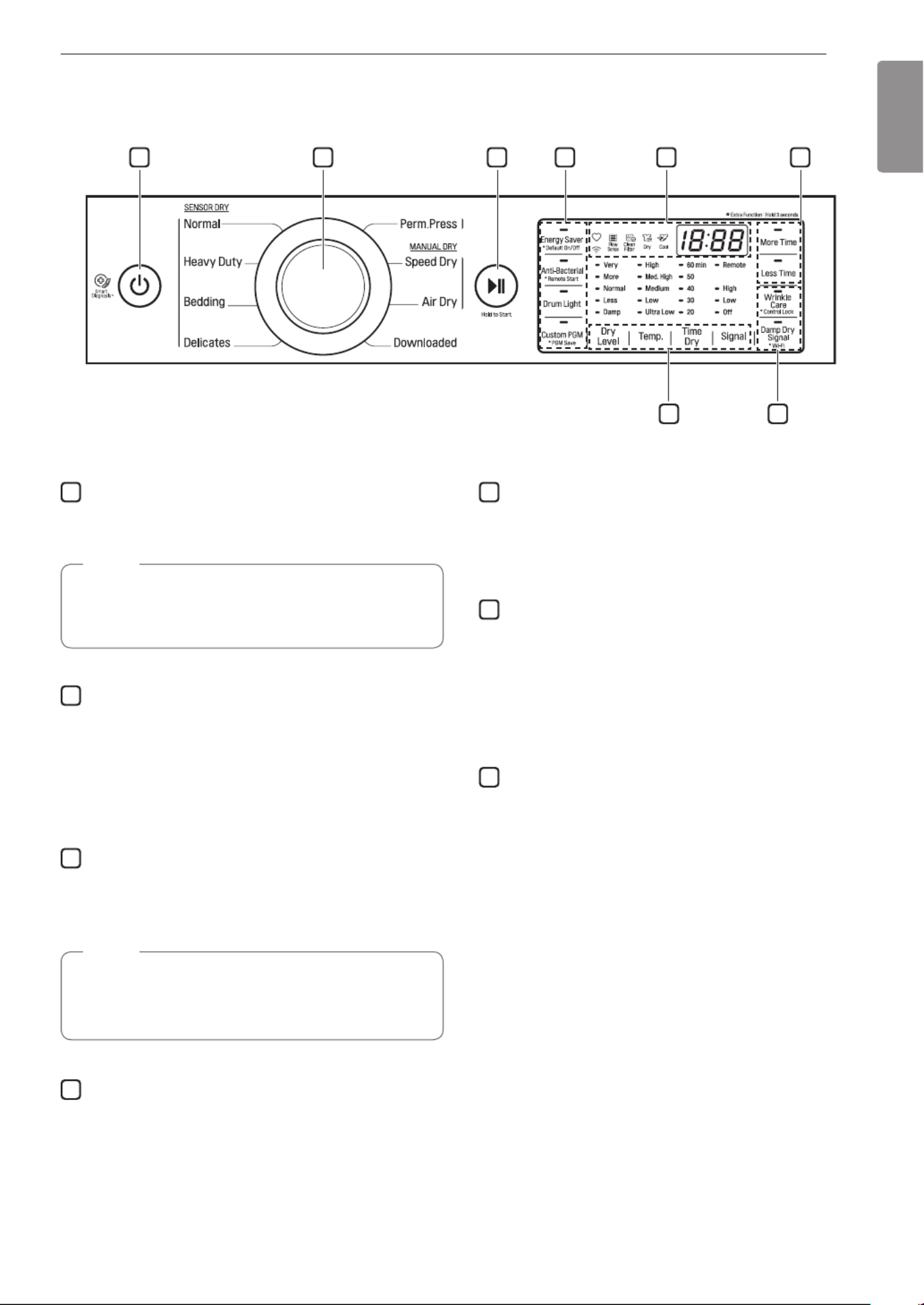
Control Panel
1 2 3 5 64
47
1
POWER Button
Press to turn the dryer ON. Press again to turn the
dryer OFF.
NOTE
Pressing the button during a cycle will POWER
cancel that cycle and any load settings will be
lost.
2
Cycle Selector Knob
Turn this knob to select the desired cycle. Once
the desired cycle has been selected, the standard
presets are shown in the display. On Manual Dry
cycles, these settings can be adjusted using the cycle
modifier buttons any time before starting the cycle.
3
START/PAUSE Button
Press this button to start the selected cycle. If the
dryer is running, use this button to pause the cycle
without losing the current settings.
NOTE
If you do not press the START/PAUSE button to
resume a cycle within 60 minutes, the dryer turns
off automatically.
4
Cycle Option Buttons
The option buttons allow you to select additional cycle
options. Certain buttons also allow you to activate
special functions by pressing and holding the button
for 3 seconds.
5
Time and Status Display
The display shows the settings, estimated time
remaining, options, and status messages for the
dryer.
6
MORE TIME/LESS TIME Buttons
Use these buttons with the Time Dry and other
Manual Dry cycles to adjust the drying time. Press the
MORE TIME button to increase the selected manual
cycle time by 1 minute; press the button LESS TIME
to decrease the cycle time by 1 minute.
7
Cycle Modifier Buttons
Use these buttons to select the desired cycle settings
for the selected cycle. The current settings are shown
in the display. Press the button for that modifier to
select other settings.
Produkt Specifikationer
| Mærke: | LG |
| Kategori: | Tørretumbler |
| Model: | D7301WE |
Har du brug for hjælp?
Hvis du har brug for hjælp til LG D7301WE stil et spørgsmål nedenfor, og andre brugere vil svare dig
Tørretumbler LG Manualer

6 Februar 2025
6 Februar 2025
1 Januar 2025
22 December 2024
22 December 2024
19 December 2024
19 December 2024
19 December 2024
6 September 2024
2 September 2024
Tørretumbler Manualer
- Tørretumbler DeLonghi
- Tørretumbler Sinbo
- Tørretumbler Bosch
- Tørretumbler PKM
- Tørretumbler Gram
- Tørretumbler EasyMaxx
- Tørretumbler Siemens
- Tørretumbler Samsung
- Tørretumbler Scandomestic
- Tørretumbler GE
- Tørretumbler Zanussi
- Tørretumbler Cylinda
- Tørretumbler Panasonic
- Tørretumbler Candy
- Tørretumbler Fisher & Paykel
- Tørretumbler Gorenje
- Tørretumbler VOX
- Tørretumbler Miele
- Tørretumbler Blomberg
- Tørretumbler Concept
- Tørretumbler Teka
- Tørretumbler OK
- Tørretumbler AEG
- Tørretumbler Electrolux
- Tørretumbler Bauknecht
- Tørretumbler Whirlpool
- Tørretumbler Vestfrost
- Tørretumbler Mitsubishi
- Tørretumbler Master
- Tørretumbler Sharp
- Tørretumbler Hotpoint
- Tørretumbler Omega
- Tørretumbler Hoover
- Tørretumbler Daewoo
- Tørretumbler Arçelik
- Tørretumbler ProfiCare
- Tørretumbler Grundig
- Tørretumbler Indesit
- Tørretumbler Hotpoint Ariston
- Tørretumbler Klarstein
- Tørretumbler Ardo
- Tørretumbler Etna
- Tørretumbler Infiniton
- Tørretumbler Emerio
- Tørretumbler Logik
- Tørretumbler Bartscher
- Tørretumbler Sauber
- Tørretumbler Westinghouse
- Tørretumbler Element
- Tørretumbler Thomson
- Tørretumbler Constructa
- Tørretumbler Hyundai
- Tørretumbler AKAI
- Tørretumbler Hisense
- Tørretumbler Brandt
- Tørretumbler Adler
- Tørretumbler Black And Decker
- Tørretumbler Camry
- Tørretumbler TecLime
- Tørretumbler Blaupunkt
- Tørretumbler Tomado
- Tørretumbler AEG-Electrolux
- Tørretumbler Ariston
- Tørretumbler Asko
- Tørretumbler Atlas
- Tørretumbler Becken
- Tørretumbler BEKO
- Tørretumbler Gaggenau
- Tørretumbler Iberna
- Tørretumbler Ignis
- Tørretumbler Küppersbusch
- Tørretumbler Neff
- Tørretumbler Privileg
- Tørretumbler Smeg
- Tørretumbler Clatronic
- Tørretumbler Noveen
- Tørretumbler Remington
- Tørretumbler Ariston Thermo
- Tørretumbler Fagor
- Tørretumbler Haier
- Tørretumbler Bomann
- Tørretumbler Russell Hobbs
- Tørretumbler Ariete
- Tørretumbler Leifheit
- Tørretumbler Vivax
- Tørretumbler Crosley
- Tørretumbler UPO
- Tørretumbler Zanker
- Tørretumbler Galanz
- Tørretumbler Amana
- Tørretumbler Amica
- Tørretumbler Arthur Martin-Electrolux
- Tørretumbler Euromaid
- Tørretumbler Kernau
- Tørretumbler Caple
- Tørretumbler SIBIR
- Tørretumbler Zerowatt
- Tørretumbler Taurus
- Tørretumbler Veripart
- Tørretumbler Zenith
- Tørretumbler Balay
- Tørretumbler Exquisit
- Tørretumbler Pelgrim
- Tørretumbler Elba
- Tørretumbler Elektra Bregenz
- Tørretumbler ELIN
- Tørretumbler Faure
- Tørretumbler Rommer
- Tørretumbler Schneider
- Tørretumbler MPM
- Tørretumbler Profilo
- Tørretumbler Tesla
- Tørretumbler Hanseatic
- Tørretumbler Thor
- Tørretumbler V-Zug
- Tørretumbler Maytag
- Tørretumbler Auto Joe
- Tørretumbler Schulthess
- Tørretumbler Thomas
- Tørretumbler Bush
- Tørretumbler Heylo
- Tørretumbler Aspes
- Tørretumbler Salora
- Tørretumbler Inventum
- Tørretumbler Cleanmaxx
- Tørretumbler White Knight
- Tørretumbler Midea
- Tørretumbler CDA
- Tørretumbler Frigidaire
- Tørretumbler Frilec
- Tørretumbler Bimar
- Tørretumbler Esatto
- Tørretumbler SVAN
- Tørretumbler Everglades
- Tørretumbler Danby
- Tørretumbler RCA
- Tørretumbler Koenic
- Tørretumbler ECG
- Tørretumbler General Electric
- Tørretumbler Eldom
- Tørretumbler Proline
- Tørretumbler Stirling
- Tørretumbler Saivod
- Tørretumbler ElectriQ
- Tørretumbler Lavorwash
- Tørretumbler Gemini
- Tørretumbler Rinnai
- Tørretumbler Friac
- Tørretumbler Technika
- Tørretumbler Seiki
- Tørretumbler Baumatic
- Tørretumbler Beper
- Tørretumbler Morris
- Tørretumbler Kenmore
- Tørretumbler Avanti
- Tørretumbler Continental Edison
- Tørretumbler Corbero
- Tørretumbler Otsein-Hoover
- Tørretumbler Artusi
- Tørretumbler Orima
- Tørretumbler Magic Chef
- Tørretumbler Lamona
- Tørretumbler Philco
- Tørretumbler Zanussi-Electrolux
- Tørretumbler Sôlt
- Tørretumbler Rex
- Tørretumbler Classique
- Tørretumbler Kunft
- Tørretumbler Simpson
- Tørretumbler Euro Appliances
- Tørretumbler Summit
- Tørretumbler Kogan
- Tørretumbler LERAN
- Tørretumbler New Pol
- Tørretumbler Insignia
- Tørretumbler Andis
- Tørretumbler Jocel
- Tørretumbler Ufesa
- Tørretumbler SanGiorgio
- Tørretumbler Electra
- Tørretumbler IFB
- Tørretumbler Mistral
- Tørretumbler Wisberg
- Tørretumbler KDK
- Tørretumbler AYA
- Tørretumbler Vedette
- Tørretumbler Royal Sovereign
- Tørretumbler Nordland
- Tørretumbler John Lewis
- Tørretumbler Mabe
- Tørretumbler Castor
- Tørretumbler Heinner
- Tørretumbler Nabo
- Tørretumbler Defy
- Tørretumbler Nordmende
- Tørretumbler WLA
- Tørretumbler Ansonic
- Tørretumbler Kelvinator
- Tørretumbler Listo
- Tørretumbler EAS Electric
- Tørretumbler Speed Queen
- Tørretumbler WhiteLine
- Tørretumbler Creda
- Tørretumbler Kleenmaid
- Tørretumbler Essentiel B
- Tørretumbler Edy
- Tørretumbler Altus
- Tørretumbler Eurotech
- Tørretumbler Equator
- Tørretumbler Coline
- Tørretumbler Trieste
- Tørretumbler Teco
- Tørretumbler Bluesky
- Tørretumbler Icecool
- Tørretumbler Marynen
- Tørretumbler Ormond
- Tørretumbler Sichler
- Tørretumbler Eudora
- Tørretumbler Hiberg
- Tørretumbler Romo
- Tørretumbler Microstar
- Tørretumbler Amba
- Tørretumbler Winia
- Tørretumbler Huebsch
- Tørretumbler Novamatic
- Tørretumbler T4223C
- Tørretumbler Miele Professional
- Tørretumbler Mio Star
- Tørretumbler One Concept
- Tørretumbler Dexter Laundry
- Tørretumbler TESLA Electronics
- Tørretumbler Smart Brand
- Tørretumbler Mybeo
- Tørretumbler CEEM
- Tørretumbler Ulsonix
- Tørretumbler Yamazen
- Tørretumbler Onix
Nyeste Tørretumbler Manualer

24 Marts 2025
24 Marts 2025
24 Marts 2025

21 Marts 2025
15 Marts 2025

15 Marts 2025
15 Marts 2025
15 Marts 2025
15 Marts 2025
15 Marts 2025