Lowrance M68C S/Map Manual
Læs nedenfor 📖 manual på dansk for Lowrance M68C S/Map (176 sider) i kategorien Navigator. Denne guide var nyttig for 34 personer og blev bedømt med 4.5 stjerner i gennemsnit af 2 brugere
Side 1/176

Pub. 988-0152-031
www.lowrance.com
M68C S/Map &
M68C IceMachine
Fish-finding Sonar & Mapping GPS
Installation and Operation
Instructions

i
Table of Contents
Sec. 1: Read Me First! .............................................................. 1
Capabilities and Specifications: M68............................................ 3
How your Sonar Works................................................................. 4
How your GPS Works ................................................................... 5
Introduction to GPS and WAAS................................................... 5
How to Use this Manual: Typographical Conventions................ 7
Sec. 2: Installation & Accessories .......................................... 9
Preparations.................................................................................. 9
Transducer Installation................................................................ 9
Recommended Tools and Supplies ......................................... 10
Selecting a Transducer Location................................................ 10
How Low Should You Go?....................................................... 11
Shoot-Thru-Hull vs. Transom Mounting ............................... 12
Transom Transducer Assembly and Mounting ......................... 13
Trolling Motor Bracket Installation........................................... 16
Transducer Orientation and Fish Arches.................................. 17
Shoot-Thru-Hull Preparation and Installation ......................... 18
Power and Cable Connections.................................................... 22
Mounting the Sonar Unit: In-Dash or Bracket ......................... 23
Portable Sonar Installation........................................................ 27
Portable Transducer Assembly .............................................. 29
Sec. 3: Basic Sonar Operation.............................................. 31
Keyboard Basics.......................................................................... 31
Memory........................................................................................ 32
Menus .......................................................................................... 32
Main Menu .............................................................................. 32
Sonar Menu ............................................................................. 33
Pages ........................................................................................... 35
Basic Sonar Quick Reference ............................................... 37
Sonar Operations ........................................................................ 38
Fish Symbols vs. Full Sonar Chart ........................................ 40
Other Free Training Aids ....................................................... 41
Sec. 4: Sonar Options & Other Features ........................... 43
ASP (Advanced Signal Processing)......................................... 43
Alarms ......................................................................................... 44
Depth Alarms .......................................................................... 44
Zone Alarm.............................................................................. 45
Fish Alarm............................................................................... 46
Chart Speed................................................................................. 47
ColorLine.................................................................................. 47
Depth Cursor............................................................................... 49
Depth Range - Automatic ........................................................... 49

ii
Depth Range - Manual................................................................ 50
Turn Auto Depth Range on Again:..................................... 50
Depth Range - Upper and Lower Limits ................................... 50
FasTrack .................................................................................. 52
Fish I.D. (Fish Symbols & Depths) ......................................... 52
FishTrack ................................................................................. 53
Overlay Data............................................................................... 54
Change Displayed Data Font Size: ........................................ 55
Ping Speed & HyperScroll....................................................... 56
Reset Options.............................................................................. 57
Sensitivity & Auto Sensitivity.................................................... 58
Turn Auto Sensitivity Back on:.............................................. 59
Set Keel Offset ............................................................................ 59
Sonar Color Mode........................................................................ 60
Sonar Page & Sonar Chart Display Options ............................. 61
Full Sonar Chart ..................................................................... 61
Split Zoom Sonar Chart.......................................................... 61
Digital Data/Chart .................................................................. 62
Flasher..................................................................................... 62
Sonar Simulator.......................................................................... 63
Stop Chart ................................................................................... 63
Surface Clarity ............................................................................ 64
Zoom Pan..................................................................................... 65
Sec. 5: Ice Fishing.................................................................... 67
Icemachine Mode Operation....................................................... 68
Sensitivity ............................................................................... 70
Colorline.............................................................................. 71
Battery Gauge ......................................................................... 72
Sonar Signal Interpretation ....................................................... 72
Ice Flasher Options..................................................................... 73
Split Zoom Display Mode........................................................ 73
Color Modes............................................................................. 74
Scouting Through the Ice ........................................................... 75
Sec. 6: Sonar Troubleshooting.............................................. 77
Sec. 7: Basic GPS Operations................................................ 81
Keyboard ..................................................................................... 81
Power/Lights (Turn Unit On and Off) ....................................... 82
Main Menu .................................................................................. 82
Pages ........................................................................................... 84
Sonar Page .............................................................................. 84
Satellite Status Page .............................................................. 84
Navigation Page...................................................................... 86
Full Map Page ......................................................................... 88

iii
GPS Quick Reference ............................................................. 91
Find your Current Position ........................................................ 92
Moving around the Map: Zoom & Cursor Arrow Keys.............. 92
Selecting any Map Item with the Cursor .................................. 93
Set a Waypoint............................................................................ 93
Create Waypoint at Current Position.................................... 93
Create Waypoint on Map........................................................ 94
Create Waypoint by Entering a Position ............................... 95
Navigate to a Waypoint .............................................................. 95
Set Man Overboard (MOB) Waypoint........................................ 96
Navigate Back to MOB Waypoint.............................................. 96
Navigate to Cursor Position on Map.......................................... 97
Navigate to a Map Place............................................................. 99
Creating and Saving a Trail....................................................... 99
Displaying a Saved Trail .......................................................... 101
Navigating Trails...................................................................... 101
Visual Trailing ...................................................................... 102
Navigate a Trail (Forward)................................................... 102
Navigate a Back Trail (Backtrack, or Reverse) ................... 104
Cancel Navigation..................................................................... 105
Sec. 8: Advanced GPS Operations .....................................107
Find Distance from Current Position to Another Location .... 107
Find Distance from Point to Point ........................................... 107
Icons........................................................................................... 107
Create Icon on Map............................................................... 108
Create Icon at Current Position........................................... 108
Delete an Icon ....................................................................... 108
Navigate to an Icon ............................................................... 109
Routes........................................................................................ 109
Create and Save a Route ...................................................... 110
Delete a Route ....................................................................... 112
Edit a Route .......................................................................... 112
Navigate a Route................................................................... 113
Navigate a Route in Reverse ................................................ 114
Trails ......................................................................................... 115
Delete a Trail ........................................................................ 115
Edit a Trail Name ................................................................. 115
Edit a Trail Color .................................................................. 116
Edit a Trail Pattern .............................................................. 116
Utilities...................................................................................... 116
Alarm Clock........................................................................... 116
Sun/Moon Rise & Set Calculator.......................................... 116
Trip Calculator...................................................................... 116

iv
Trip Down Timer................................................................... 116
Trip Up Timer ....................................................................... 117
Waypoints.................................................................................. 117
Delete a Waypoint................................................................. 117
Edit a Waypoint (Name, Symbol and Position) ................... 117
Selecting a Waypoint ............................................................ 118
Set a Waypoint by Average Position .................................... 118
Set a Waypoint by Projecting a Position.............................. 118
Sec. 9: System & GPS Setup Options................................. 119
Alarms ....................................................................................... 119
Auto Satellite Search................................................................ 120
Coordinate System Selection.................................................... 121
Map Fix ..................................................................................... 122
Customize Page Displays ......................................................... 124
Customize Map or Navigation Page..................................... 124
Customize Position Page ...................................................... 124
GPS Simulator .......................................................................... 125
Simulating Trail or Route Navigation ................................. 126
Initialize GPS............................................................................ 126
Map Auto Zoom......................................................................... 127
Map Data................................................................................... 127
Earth Map Detail .................................................................. 127
Pop-Up Map Info................................................................... 128
Fill Water with White........................................................... 128
Map Overlays (Range Rings; Lat/Long Grid) ...................... 128
Map Datum Selection ............................................................... 128
Map Detail Category Selection................................................. 129
Map Orientation ....................................................................... 130
Overlay Data............................................................................. 131
Pop-Up Help.............................................................................. 133
Reset Options............................................................................ 134
Screen Contrast and Brightness .............................................. 134
Set Language ............................................................................ 135
Set Local Time .......................................................................... 135
Show WAAS Alarm................................................................... 136
Software Version Information.................................................. 136
Sounds and Alarm Sound Styles.............................................. 137
Track Smoothing....................................................................... 138
Trail Options ............................................................................. 138
Delete All Trails .................................................................... 139
Update Active Trail Option .................................................. 139
Update Trail Criteria (Auto, Time, Distance).................. 139
Trail Update Rate (Time, Distance)................................. 139

v
Delete Trail ........................................................................... 140
New Trail............................................................................... 140
Trail Visible/Invisible and Other Trail Options .................. 141
Transparency ............................................................................ 141
Units of Measure....................................................................... 142
Sec. 10: Searching................................................................. 143
Find any Item Selected by Map Cursor ................................... 143
Find Map Places........................................................................ 144
Find Streets or Intersections.................................................... 146
Find Waypoints......................................................................... 150
Sec. 11: Supplemental Material..........................................153
Index......................................................................................... 159
WARNING!
A CAREFUL NAVIGATOR NEVER RELIES ON ONLY ONE METHOD
TO OBTAIN POSITION INFORMATION.
CAUTION
When showing navigation data to a position (waypoint), a GPS unit will show
the shortest, most direct path to the waypoint. It provides navigation data to the
waypoint regardless of obstructions. Therefore, the prudent navigator will not
only take advantage of all available navigation tools when traveling to a way-
point, but will also visually check to make sure a clear, safe path to the waypoint
is always available.
WARNING!
When a GPS unit is used in a vehicle, the vehicle operator is solely re-
sponsible for operating the vehicle in a safe manner. Vehicle operators
must maintain full surveillance of all pertinent driving, boating or fly-
ing conditions at all times. An accident or collision resulting in damage
to property, personal injury or death could occur if the operator of a
GPS-equipped vehicle fails to pay full attention to travel conditions and
vehicle operation while the vehicle is in motion.

vi
Notes

1
Section 1:
Read Me First!
How this manual can get you out on the water, fast!
Welcome to the exciting world of digital sonar and GPS! We know
you're anxious to begin finding fish, but we have a favor to ask. Before
you grab the unit and begin installing it, please give us a moment or
two to explain how our manual can help you get the best performance
from your combination fish finder and GPS receiver.
First, we want to thank you for buying a Lowrance sonar/GPS unit.
Whether you're a first time user or a professional fisherman, you'll dis-
cover that your unit is easy to use, yet capable of handling demanding
navigation and sonar tasks.
Our goal for this book is to get you on the water fast, with a minimum
of fuss. Like you, we'd rather spend more time boating or fishing and
less time reading the manual!
So, we designed our book so that you don't have to read the whole thing
from front to back for the information you want. At the start (or end) of
each segment, we'll tell you what content is coming up next. If it's a
concept you're already familiar with, we'll show you how and where to
skip ahead for the next important topic. We've also made it easy to look
up any tips you may need from time to time. Here's how:
The manual is organized into 11 sections. This first section is an intro-
duction to the M68 sonar and GPS. It tells you the basics you need to
know before you can make the unit look around and tell you where you
are, or look below the surface to find some fish.
Section 2 will help you install your unit, as well as the transducer (the
most important part of any sonar installation). We'll also tell you about
some of the available accessories.
Section 3 covers Basic Sonar Operation. It will show you how easy it is
to run your sonar, right out of the box. This section features a one-page
Sonar Quick Reference. (If you've already jumped ahead and fig-
ured out how to install the unit yourself, and you just can't wait
any longer, turn to the Quick Reference on page 37 and head
for the water with your unit!)
After you've gained some experience with your sonar, you'll want to
check out Section 4, which discusses more advanced Sonar Options and
Other Features.
When you come to a sonar menu command on the unit's screen, you can
look it up in the manual by skimming over the table of contents or the in-

2
dex, or just flipping through Section 3 or scanning through the sonar op-
tions in Section 4.
Section 5 is a brief introduction to the powerful ice fishing applications of
the M68C and M68C IceMachine. (See section 2 to learn how you can get
the most out of your M68C with the addition of a special portable power
pack for ice fishing.)
If you're having difficulty with your sonar, you can find an answer to
the most common problems in Section 6, Sonar Troubleshooting.
The manual switches from sonar to navigation in Section 7, which in-
troduces you to Basic GPS Operations. This section features a one-
page GPS Quick Reference on page 91.
Section 7 contains short, easy-to-scan GPS lessons that follow one an-
other in chronological order. They're all you'll need to know to find your
way on the water quickly.
After you've learned the basics (or if you already have some GPS expe-
rience), you may want to try out some of the unit's many advanced
navigation features. That brings us to Section 8, Advanced GPS Opera-
tions. This section contains the rest of the unit's GPS command func-
tions, organized in alphabetical order.
When you come to a GPS menu command on the screen, you can look it up
in the manual by skimming over the table of contents or index, just flipping
through Section 7 or scanning through the command portion of Section 8.
This unit is ready to use right out of the box, but you can fine tune and
customize its operation with dozens of options. Since sonar is the unit's
key feature, we put the main sonar options in Section 4. Some options,
such as screen brightness settings, affect both sonar and GPS opera-
tions. We describe how to use those common options along with GPS
options in Section 9, System Setup and GPS Setup Options. Section 9 is
organized in alphabetical order.
In Section 10, we go into more detail on one of the unit's most remarkable
GPS capabilities — Searching. There are so many map items you can
search for, we had to give this function its own section in the manual!
Finally, in Section 11, we offer Supplemental Material, including a list
of the GPS datums used, warranties and customer service information.
Now, if you're into the fine details, glance over the next segment on
specifications to see just how much sonar and GPS power your unit con-
tains. It's important to us (and our power users), but, if don't careyou
how many watts of power the unit has, or how many waypoints it can
store, skip ahead to important information on how sonar works, on page
4. (Background on GPS begins on page 5.)

3
Capabilities and Specifications: M68
General
Display:............................ High-contrast Film SuperTwist LCD. Diago-
nal viewing area: 3.5" (8.9 cm).
Resolution:...................... 160 pixel x 240 pixel resolution; 38,400 total
pixels.
Backlighting:.................. LED backlit screen with multiple lighting lev-
els; backlit keypad.
Input power:................... 10 to 17 volts DC.
Current drain: ............... 170 ma lights off; 240 ma lights on.
Case size:......................... 5.8" H x 4.3" W x 2.5" D (14.7 cm H x 10.8 cm
W x 6.6 cm D) sealed, waterproof; suitable for
saltwater use.
Back-up memory: .......... Built-in memory stores GPS data for dec-
ades. User settings are stored when unit is
turned off.
Languages:...................... 10; menu languages selectable by user.
Sonar
Frequency:...................... 200 kHz.
Transducer:...................... A Skimmer transducer comes packed with
your sonar unit. Its 20° cone angle offers a
wide fish detection area of up to 60º with
high sensitivity settings. Operates at boat
speeds up to 70 mph (61 kts).
Transmitter: ................... 800 watts peak-to-peak; 100 watts RMS.
Sonar sounding
depth capability: ........... 600 feet (180 meters). Actual capability de-
pends on transducer configuration and in-
stallation, bottom composition and water con-
ditions. All sonar units typically read deeper
in fresh water than in salt water.
Depth display:................ Continuous display.
Audible alarms: ............. Deep/shallow/fish/zone.
Automatic ranging:....... Yes, with instant screen updates.
Auto bottom track:........ Yes
Zoom bottom track: ...... Yes.
Split-screen zoom:......... Yes.
Surface water temp: ..... Yes, built into transducer.

5
display, where an image of the object appears on the scrolling sonar
chart. The sonar's microprocessor calculates the time lapse between the
transmitted signal and echo return to determine the distance to the
object. The whole process repeats itself several times each second.
How Your GPS Works
You'll navigate faster and easier if you understand how this unit scans
the sky to tell you where you are on the earth — and, where you're go-
ing. (But if you already have a working understanding of GPS receivers
and the GPS navigation system, skip on ahead to Section 2, Installation
& Accessories on page 9. If you're new to GPS, read on, and you can later
impress your friends with your new-found knowledge.)
First, think of your unit as a small but powerful computer. (But don't
worry — we made this unit easy to use, so you don't need to be a computer
expert to find your way!) The unit includes a keypad and a screen with
menus so you can tell it what to do. The screen also lets the unit show your
location on a moving map, as well as point the way to your destination.
This unit uses an internal antenna/receiver module, which makes the
whole system work something like your car radio. But instead of your
favorite dance tunes, this receiver tunes in to a couple of dozen GPS
satellites circling the earth. (It will also listen in to the WAAS satellites
in orbit, but more about that in the upcoming segment introducing you
to GPS and WAAS.)
Your unit listens to signals from as many satellites as it can "see" above
the horizon, eliminates the weakest signals, then computes its location
in relation to those satellites. Once it figures its latitude and longitude,
the unit plots that position on the GPS screen. The whole process takes
place several times a second!
Another portion of the unit's onboard memory is devoted to recording GPS
navigation information, which includes waypoints, event marker icons,
trails and routes. This lets you look back the way you came, and retrace
your path. Think of this data storage like the hard drive memory in a
computer or a tape in a cassette tape recorder. You can save several dif-
ferent GPS data files, erase 'em and record new ones, over and over again.
Introduction to GPS and WAAS
Well, now you know the basics of how the unit does its work. You might
be ready to jump ahead to Section 2, Installation & Accessories, on page
13, so you can mount your unit and plug in the power. Or you might
want to see how our text formatting makes the manual tutorials easy to
skim. If that's the case, move on to "How to Use This Manual" on page
10. But, if you want to understand the current state of satellite naviga-
tion, look over this segment describing how GPS and its new companion

6
WAAS work together to get you where you're going.
The Global Positioning System (GPS) was launched July 17, 1995 by
the United States Department of Defense. It was designed as a 24-
hour-a-day, 365-days-a-year, all weather global navigation system for
the armed forces of the U.S. and its allies. Civilian use was also avail-
able at first, but it was less accurate because the military scrambled
the signal somewhat, using a process called Selective Availability (SA.)
GPS proved so useful for civilian navigation that the federal govern-
ment discontinued SA on May 2, 2000, after the military developed
other methods to deny GPS service to enemy forces. Reliable accuracy
for civilian users jumped from 100 meters (330 feet) under SA to the
present level of 10 to 20 meters (about 30 to 60 feet.)
Twenty-four satellites orbit 10,900 nautical miles above the Earth,
passing overhead twice daily. A series of ground stations (with precisely
surveyed locations) controls the satellites and monitors their exact loca-
tions in the sky. Each satellite broadcasts a low-power signal that identi-
fies the satellite and its position above the earth. Three of these satellites
are spares, unused until needed. The rest virtually guarantee that at
least four satellites are in view nearly anywhere on Earth at all times.
The system requires signal reception from three satellites in order to
determine a position. This is called a 2D fix. It takes four satellites to
determine both position and elevation (your height above sea level —
also called altitude). This is called a 3D fix.
A minimum of three satellites are required to determine a 2D fix.
Remember, the unit must have a clear view of the satellites in order to
receive their signals. Unlike radio or television signals, GPS works at
very high frequencies. These signals can be easily blocked by trees,
buildings, an automobile roof, even your body.

7
Like most GPS receivers, this unit doesn’t have a compass or any other
navigation aid built inside. It relies solely on the signals from the sat-
ellites to calculate a position. Speed, direction of travel, and distance
are all calculated from position information. Therefore, in order for the
unit to determine direction of travel, you must be moving and the
faster, the better. This is not to say that it won’t work at walking or
trolling speeds — it will. There will simply be more "wandering" of the
data shown on the display.
GPS alone is plenty accurate for route navigation, but the U.S. Federal
Aviation Administration has special aircraft navigation needs that go
beyond basic GPS. So, the FAA has developed a program to boost GPS
performance with its Wide Area Augmentation System, or WAAS. The
FAA commissioned the system on July 11, 2003.
WAAS is designed to increase GPS accuracy to within 7.6 meters vertically
and horizontally, but it consistently delivers accuracies within 1-2 meters
horizontal and 2-3 meters vertical, according to the FAA. It does this by
broadcasting correction signals on GPS frequencies. Your unit automati-
cally receives both GPS and WAAS signals.
However, there are some fringe areas of the U.S., including parts of
Alaska, that do not yet receive robust WAAS coverage. Continued WAAS
development is planned to extend WAAS coverage in the years to come.
WAAS boosts the accuracy of land GPS navigation, but the system is
designed for aircraft. The satellites are in a fixed orbit around the
Equator, so they appear very low in the sky to someone on the ground
in North America. Aircraft and vessels on open water can get consis-
tently good WAAS reception, but terrain, foliage or even large man-made
structures can sometimes block the WAAS signal from ground receivers.
You'll find that using your GPS receiver is both easy and amazingly
accurate. It’s easily the most accurate method of electronic navigation
available to the general public today. Remember, however, that this
receiver is only a tool. Always have another method of navigation avail-
able, such as a map or chart and a compass.
Also remember that this unit will always show navigation information
in the shortest line from your present position to a waypoint, regardless
of terrain! It only calculates position, it can’t know what’s between you
and your destination, for example. It’s up to you to safely navigate
around obstacles, no matter how you’re using this product.
How to use this manual: typographical conventions
Many instructions are listed as numbered steps. The keypad and arrow
"keystrokes" appear as boldface type. So, if you're in a real hurry (or
just need a reminder), you can skim the instructions and pick out what

8
menu command to use by finding the boldface command text. The fol-
lowing paragraphs explain how to interpret the text formatting for
those commands and other instructions:
Arrow Keys
The arrow keys control the movement of dotted cross-hair lines on your
mapping screen called the cursor. The arrow keys also control a hori-
zontal line depth cursor on the sonar screen. The arrow keys help you
move around the menus so you can execute different commands. They
are represented by symbols like these, which denote the down arrow
key, the up arrow, the left arrow and the right arrow: ↓
↓
↓
↓↓ ↑
↑
↑
↑↑ ←
←
←
←← →
→
→
→→ .
Keyboard
The other keys perform a variety of functions. When the text refers to a
key to press, the key is shown in bold, sans serif type. For example, the
"Enter/Icons" key is shown as ENT and the "Menu" key is shown as MENU.
Menu Commands
A menu command or a menu option will appear in small capital letters, in
a bold sans serif type like this: R POUTE LANNING. These indicate that you are
to select this command or option from a menu or take an action of some
kind with the menu item. Text that you may need to enter or file names
you need to select are show in italic type, such as trail name.
Instructions = Menu Sequences
Most functions you perform with this unit are described as a sequence
of key strokes and selecting menu commands. We've written them in a
condensed manner for quick and easy reading.
For example, instructions for navigating a trail would look like this:
1. From the Plotter Page, press MENU MENU| |↓
↓
↓
↓↓ to M TY RAILS|ENT.
2. Press ↓
↓
↓
↓↓ to Trail 1|ENT ENT| |
→
→
→
→→ ↓
↓
↓
↓↓ to NAVIGATE| .
3. You are asked to wait while it converts the trail into a route.
4. The wait message disappears and the unit begins showing navi-
gation information along the trail. Now, begin moving and follow
your unit's directions.
Translated into complete English, step 1 above would mean: "Start on
the Plotter Page. Press the Menu key twice. Next, repeatedly press (or
press and hold) the down arrow key to scroll down the menu and select
(highlight) the My Trails menu command. Finally, press the Enter key."
Step 2 would mean: "Press the down arrow key repeatedly to scroll to
the trail named Trail 1, and press Enter. Next, press the right arrow
key and then the down arrow key to highlight the Navigate command,
then press Enter."

9
Section 2:
Installation & Accessories
Preparations
You can install the sonar and GPS systems in some other order if you
prefer, but we recommend this installation sequence:
CAUTION:
You should read over this entire installation section before drill-
ing any holes in your vehicle or vessel!
1. Determine the approximate location for the sonar/GPS unit, so you
can plan how and where to route the power/transducer cable. This will
help you make sure you have enough cable length for the desired con-
figuration.
2. Determine the approximate location for the transducer and its cable
route.
3. Determine the location of your battery or other power connection,
along with the power cable route.
4. Install the transducer and route the transducer cable to the so-
nar/GPS unit.
5. Route the power cable from the unit's location to an appropriate
power source and connect it there.
6. Connect the transducer/power cable to the unit and mount the so-
nar/GPS unit to the bracket.
Transducer Installation
These instructions will help you install your Skimmer transducer on a
transom, on a trolling motor or inside a hull. Please read all instruc-
tions before proceeding with any installation.
Your Skimmer transducer typically comes packaged with a one-piece
stainless steel bracket for mounting it to the transom of your boat. The
optional trolling motor mount uses a one-piece plastic bracket with an
adjustable strap. These are "kick-up" mounting brackets. They help pre-
vent damage if the transducer strikes an object while the boat is moving.
If the transducer does "kick-up," the bracket can easily be pushed back
into place without tools.
Read these instructions carefully before attempting the installation.
Determine which of the installation methods is right for your boat.
13
Second, the transducer angle cannot be adjusted for the best fish arches
on your sonar display. (This is not an issue for flasher-style sonars.)
Lack of angle adjustment can be particularly troublesome on hulls that
sit with the bow high when at rest or at slow trolling speeds.
Third, a transducer CAN NOT shoot through wood and metal hulls.
Those hulls require either a transom mount or a thru-hull installation.
Fourth, if your Skimmer transducer has a built in temp sensor, it will
only show the temperature of the bilge, not the water surface temp.
Follow the testing procedures listed in the shoot-thru-hull installation
section at the end of this lesson to determine if you can satisfactorily
shoot through the hull.
TRANSOM TRANSDUCER ASSEMBLY AND MOUNTING
The best way to install the transducer is to loosely assemble all of the
parts first, place the transducer's bracket against the transom and see if
you can move the transducer so that it's parallel with the ground.
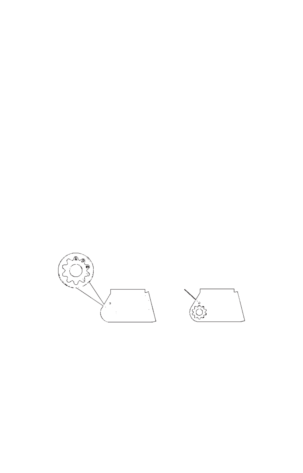
1. Assembling the bracket. Press the two small plastic ratchets into the
sides of the metal bracket as shown in the following illustration. Notice
there are letters molded into each ratchet. Place each ratchet into the
bracket with the letter "A" aligned with the dot stamped into the metal
bracket. This position sets the transducer's coarse angle adjustment for a
14° transom. Most outboard and stern-drive transoms have a 14 angle.°
Align plastic ratchets in bracket.
2. Aligning the transducer on the transom. Slide the transducer
between the two ratchets. Temporarily slide the bolt though the
transducer assembly and hold it against the transom. Looking at the
transducer from the side, check to see if it will adjust so that its face
is parallel to the ground. If it does, then the "A" position is correct for
your hull.
If the transducer's face isn't parallel with the ground, remove the
transducer and ratchets from the bracket. Place the ratchets into the
holes in the bracket with the letter "B" aligned with the dot stamped
in the bracket.
Dot

14
Reassemble the transducer and bracket and place them against the
transom. Again, check to see if you can move the transducer so it's
parallel with the ground. If you can, then go to step 3. If it doesn't,
repeat step 2, but use a different alignment letter until you can place
the transducer on the transom correctly.
Insert bolt and check transducer position on transom.
3. Assembling the transducer. Once you determine the correct posi-
tion for the ratchets, assemble the transducer as shown in the fol-
lowing figure. Don't tighten the lock nut at this time.
Assemble transducer and bracket.
4. Drilling mounting holes. Hold the transducer and bracket assembly
against the transom. The transducer should be roughly parallel to the
ground. The transducer's centerline should be in line with the bottom
of the hull. Don't let the bracket extend below the hull!
Mark the center of each slot for the mounting screw pilot holes. You
will drill one hole in the center of each slot.
Drill the holes using the #29 bit (for the #10 screws).
Ratchets
Nut
Metal
washer
Metal washer
Bolt
Rubber
washers

17
3. Route the transducer cable alongside the trolling motor shaft. Use
plastic ties (not included) to attach the transducer cable to the troll-
ing motor shaft. Make sure there is enough slack in the cable for the
motor to turn freely. Route the cable to the sonar unit and the trans-
ducer is ready for use.
Transducer mounted on trolling motor, side view.
TRANSDUCER ORIENTATION AND FISH ARCHES
If you do not get good fish arches on your display, it could be because
the transducer is not parallel with the ground when the boat is at rest
in the water or at slow trolling speeds.
Transducer angles and their effects on fish arches.
Transducer aimed
too far back
Transducer aimed
too far forward
Proper transducer angle
Partial fish arches
Full fish arch
18
If the arch slopes up – but not back down – then the front of the trans-
ducer is too high and needs to be lowered. If only the back half of the
arch is printed, then the nose of the transducer is angled too far down
and needs to be raised.
NOTE:
Periodically wash the transducer's face with soap and water to re-
move any oil film. Oil and dirt on the face will reduce the sensitivity
or may even prevent operation.
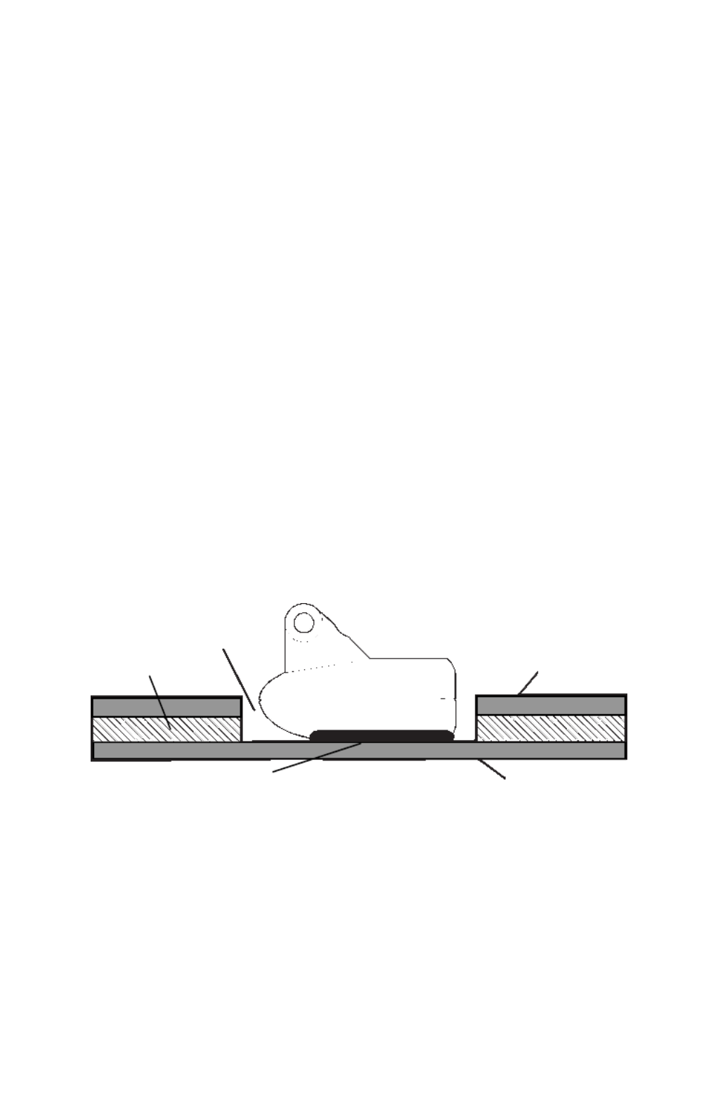
SHOOT-THRU-HULL PREPARATION
Hulls With Floatation Materials
The transducer installation inside a fiberglass hull must be in an area
that does not have air bubbles in the resin or separated fiberglass lay-
ers. The sonar signal must pass through solid fiberglass. A successful
transducer installation can be made on hulls with flotation materials
(such as plywood, balsa wood or foam) between layers of fiberglass if
the material is removed from the chosen area. See the figure below.
WARNING:
Do not remove any material from your inner hull unless
you know the hull's composition. Careless grinding or
cutting on your hull can result in damage that could sink
your boat. Contact your boat dealer or manufacturer to
confirm your hull specifications.
Epoxy the transducer to a solid portion of the hull.
For example, some (but not all) manufacturers use a layer of fiberglass,
then a core of balsa wood, finishing with an outer layer of fiberglass.
Removing the inner layer of fiberglass and the balsa wood core exposes
the outer layer of fiberglass. The transducer can then be epoxied di-
rectly to the outer layer of fiberglass. After the epoxy cures for 24
hours, fill the remaining space with polyester resin. When the job is
finished, the hull is watertight and structurally sound. Remember, the
sonar signal must pass through solid fiberglass. Any air bubbles in the
fiberglass or the epoxy will reduce or eliminate the sonar signals.
Fill with polyester resin
Inner hull
Epoxy to hull first Outer hull
Flotation material
Produkt Specifikationer
| Mærke: | Lowrance |
| Kategori: | Navigator |
| Model: | M68C S/Map |
Har du brug for hjælp?
Hvis du har brug for hjælp til Lowrance M68C S/Map stil et spørgsmål nedenfor, og andre brugere vil svare dig
Navigator Lowrance Manualer

9 August 2024
9 August 2024
3 August 2024
2 August 2024
1 August 2024
31 Juli 2024
29 Juli 2024
28 Juli 2024
28 Juli 2024
28 Juli 2024
Navigator Manualer
- Navigator SilverCrest
- Navigator Acer
- Navigator Honda
- Navigator BMW
- Navigator Toyota
- Navigator Opel
- Navigator Sony
- Navigator Mazda
- Navigator Audi
- Navigator Volkswagen
- Navigator Philips
- Navigator Pioneer
- Navigator Kenwood
- Navigator HP
- Navigator Harman Kardon
- Navigator Becker
- Navigator Garmin
- Navigator Sanyo
- Navigator Grundig
- Navigator Volvo
- Navigator Motorola
- Navigator Asus
- Navigator Bushnell
- Navigator Pyle
- Navigator Humminbird
- Navigator Sygic
- Navigator Thomson
- Navigator Skoda
- Navigator Nokia
- Navigator Mio
- Navigator Blaupunkt
- Navigator JVC
- Navigator Uniden
- Navigator Hitachi
- Navigator Medion
- Navigator Alpine
- Navigator Navman
- Navigator Parrot
- Navigator Packard Bell
- Navigator Kapsys
- Navigator Zebra
- Navigator Jensen
- Navigator VDO
- Navigator Zenec
- Navigator Kalkhoff
- Navigator TomTom
- Navigator Cobra
- Navigator Binatone
- Navigator Dual
- Navigator GlobalSat
- Navigator Celestron
- Navigator Overmax
- Navigator Midland
- Navigator Alfa Romeo
- Navigator Raymarine
- Navigator Simrad
- Navigator MaxCom
- Navigator Chrysler
- Navigator Furuno
- Navigator Navitel
- Navigator Caliber
- Navigator Lark
- Navigator Teasi
- Navigator GoClever
- Navigator Clarion
- Navigator V7
- Navigator Airis
- Navigator Audiovox
- Navigator Rand McNally
- Navigator Navigon
- Navigator IGo
- Navigator Magellan
- Navigator Scosche
- Navigator Prestigio
- Navigator Boss
- Navigator Camos
- Navigator Coyote
- Navigator Insignia
- Navigator Eagle
- Navigator Xomax
- Navigator Sylvania
- Navigator Marquant
- Navigator Lanzar
- Navigator GolfBuddy
- Navigator Soundstream
- Navigator VDO Dayton
- Navigator Dashmate
- Navigator Route 66
- Navigator Falk
- Navigator Seecode
- Navigator Nav N Go
- Navigator Pharos
- Navigator Viamichelin
- Navigator ModeCom
- Navigator Xzent
- Navigator CarTrek
- Navigator Whistler
- Navigator ESX
- Navigator Dynavin
- Navigator Cheetah
- Navigator Cydle
- Navigator LXNAV
- Navigator Planet Audio
- Navigator Eclipse
- Navigator Voice Caddie
- Navigator SkyCaddie
- Navigator TELE System
- Navigator IZZO Golf
- Navigator Zoleo
- Navigator Izzo
Nyeste Navigator Manualer

18 Januar 2025

10 Januar 2025
31 December 2025
30 December 2025
29 December 2024
29 December 2024
14 December 2024
14 December 2024
8 December 2024
8 December 2024