Supermicro A+ Server F1114S-FT Manual
Supermicro
Server
A+ Server F1114S-FT
Læs nedenfor 📖 manual på dansk for Supermicro A+ Server F1114S-FT (121 sider) i kategorien Server. Denne guide var nyttig for 11 personer og blev bedømt med 4.5 stjerner i gennemsnit af 2 brugere
Side 1/121

USER’S MANUAL
Revision 1.0a
FatTwin®
AS -F1114S-FT

The information in this User’s Manual has been carefully reviewed and is believed to be accurate. The vendor assumes
no responsibility for any inaccuracies that may be contained in this document, and makes no commitment to update
or to keep current the information in this manual, or to notify any person or organization of the updates. Please Note:
For the most up-to-date version of this manual, please see our website at www.supermicro.com.
Super Micro Computer, Inc. ("Supermicro") reserves the right to make changes to the product described in this manual
at any time and without notice. This product, including software and documentation, is the property of Supermicro and/
or its licensors, and is supplied only under a license. Any use or reproduction of this product is not allowed, except
as expressly permitted by the terms of said license.
IN NO EVENT WILL Super Micro Computer, Inc. BE LIABLE FOR DIRECT, INDIRECT, SPECIAL, INCIDENTAL,
SPECULATIVE OR CONSEQUENTIAL DAMAGES ARISING FROM THE USE OR INABILITY TO USE THIS PRODUCT
OR DOCUMENTATION, EVEN IF ADVISED OF THE POSSIBILITY OF SUCH DAMAGES. IN PARTICULAR, SUPER
MICRO COMPUTER, INC. SHALL NOT HAVE LIABILITY FOR ANY HARDWARE, SOFTWARE, OR DATA STORED
OR USED WITH THE PRODUCT, INCLUDING THE COSTS OF REPAIRING, REPLACING, INTEGRATING,
INSTALLING OR RECOVERING SUCH HARDWARE, SOFTWARE, OR DATA.
Any disputes arising between manufacturer and customer shall be governed by the laws of Santa Clara County in the
State of California, USA. The State of California, County of Santa Clara shall be the exclusive venue for the resolution
of any such disputes. Supermicro's total liability for all claims will not exceed the price paid for the hardware product.
FCC Statement: This equipment has been tested and found to comply with the limits for a Class A or Class B digital
device pursuant to Part 15 of the FCC Rules. These limits are designed to provide reasonable protection against
harmful interference when the equipment is operated in industrial environment for Class A device or in residential
environment for Class B device. This equipment generates, uses, and can radiate radio frequency energy and, if not
installed and used in accordance with the manufacturer’s instruction manual, may cause harmful interference with
radio communications. Operation of this equipment in a residential area is likely to cause harmful interference, in
which case you will be required to correct the interference at your own expense.
California Best Management Practices Regulations for Perchlorate Materials: This Perchlorate warning applies only
to products containing CR (Manganese Dioxide) Lithium coin cells. “Perchlorate Material-special handling may apply.
See ”.www.dtsc.ca.gov/hazardouswaste/perchlorate
WARNING: This product can expose you to chemicals including
lead, known to the State of California to cause cancer and birth
defects or other reproductive harm. For more information, go
to www.P65Warnings.ca.gov.
!
The products sold by Supermicro are not intended for and will not be used in life support systems, medical equipment,
nuclear facilities or systems, aircraft, aircraft devices, aircraft/emergency communication devices or other critical
systems whose failure to perform be reasonably expected to result in signicant injury or loss of life or catastrophic
property damage. Accordingly, Supermicro disclaims any and all liability, and should buyer use or sell such products
for use in such ultra-hazardous applications, it does so entirely at its own risk. Furthermore, buyer agrees to fully
indemnify, defend and hold Supermicro harmless for and against any and all claims, demands, actions, litigation, and
proceedings of any kind arising out of or related to such ultra-hazardous use or sale.
Manual Revision 1.0a
Release Date: June 23, 2022
Unless you request and receive written permission from Super Micro Computer, Inc., you may not copy any part of this
document. Information in this document is subject to change without notice. Other products and companies referred
to herein are trademarks or registered trademarks of their respective companies or mark holders.
Copyright © 2022 by Super Micro Computer, Inc.
All rights reserved.
Printed in the United States of America

4
Preface
Contents
Chapter 1 Introduction
1.1 Overview ...............................................................................................................................8
1.2 Unpacking the System .........................................................................................................8
1.3 FatTwin: System Notes ........................................................................................................9
Nodes ..................................................................................................................................9
System Power .....................................................................................................................9
1.4 System Features ................................................................................................................10
1.5 Server Chassis Features ....................................................................................................11
Node Controls ...................................................................................................................11
Front Features ...................................................................................................................12
Rear Features ...................................................................................................................13
1.6 Motherboard Layout ...........................................................................................................13
Quick Reference Table ......................................................................................................15
Chapter 2 Server Installation
2.1 Overview .............................................................................................................................17
2.2 Preparing for Setup ............................................................................................................17
Choosing a Setup Location ...............................................................................................17
Rack Precautions ..............................................................................................................17
Server Precautions ............................................................................................................18
Rack Mounting Considerations .........................................................................................18
Ambient Operating Temperature ....................................................................................18
Airow ............................................................................................................................18
Mechanical Loading .......................................................................................................18
Circuit Overloading ........................................................................................................19
Reliable Ground .............................................................................................................19
2.3 Rack Mounting Instructions ................................................................................................20
Identifying the Sections of the Rack Rails ........................................................................21
Adjusting the Rails ............................................................................................................21
Installing the Rails on a Rack ...........................................................................................22
Chassis Installation ...........................................................................................................23

5
FatTwin AS -F1114S-FT User's Manual
Chapter 3 Maintenance and Component Installation
3.1 Removing Power ................................................................................................................24
3.2 Chassis Components .........................................................................................................25
Installing and Removing the Node Drawers .....................................................................25
Removing Nodes from the Chassis ...............................................................................26
Removing the Cover from the Node..............................................................................26
Nodes and Associated Hard Drives ..................................................................................27
Installing and Removing 2.5" Hard Drives ........................................................................27
Installing Expansion Cards................................................................................................29
Assembling the PCIe Slot Bracket Assembly ................................................................30
Installing Air Shrouds ........................................................................................................32
Air Shrouds ....................................................................................................................32
Removing and Installing System Fans .............................................................................33
Removing and Installing External System Fans ............................................................33
Replacing the Power Supplies .........................................................................................34
Power Supply Replacement ..........................................................................................34
3.3 Motherboard Components ..................................................................................................35
Processor and Heatsink Installation ..................................................................................35
3.4 Memory Support and Installation .......................................................................................42
Memory Support ............................................................................................................42
DIMM Module Population ..................................................................................................43
DIMM Installation ..............................................................................................................44
DIMM Removal .................................................................................................................44
Motherboard Battery .........................................................................................................45
Chapter 4 Motherboard Connections
4.1 Power Connections ............................................................................................................46
4.2 Headers and Connectors ...................................................................................................47
4.3 Front I/O Ports ....................................................................................................................51
4.4 Jumpers ..............................................................................................................................53
Explanation of Jumpers .................................................................................................53
4.5 LED Indicators ....................................................................................................................55

6
Preface
Chapter 5 Software
5.1 Microsoft Windows OS Installation .....................................................................................57
5.2 Driver Installation ................................................................................................................59
5.3 SuperDoctor® 5 ...................................................................................................................60
5.4 IPMI ....................................................................................................................................61
BMC ADMIN User Password ............................................................................................61
Chapter 6 UEFI BIOS
6.1 Introduction .........................................................................................................................62
Starting the Setup Utility ...................................................................................................62
6.2 Main Setup .........................................................................................................................63
6.3 Advanced ............................................................................................................................65
6.4 IPMI ....................................................................................................................................82
6.5 Event Logs .........................................................................................................................85
6.6 Security ...............................................................................................................................87
6.7 Boot ....................................................................................................................................89
6.8 Save & Exit .........................................................................................................................91
Appendix A Standardized Warning Statements for AC Systems
Appendix B System Specications
Appendix C UEFI BIOS Recovery
Appendix D BSMI Safety Warnings

7
Contacting Supermicro
Headquarters
Address: Super Micro Computer, Inc.
980 Rock Ave.
San Jose, CA 95131 U.S.A.
Tel: +1 (408) 503-8000
Fax: +1 (408) 503-8008
Email: marketing@supermicro.com (General Information)
support@supermicro.com (Technical Support)
Website: www.supermicro.com
Europe
Address: Super Micro Computer B.V.
Het Sterrenbeeld 28, 5215 ML
's-Hertogenbosch, The Netherlands
Tel: +31 (0) 73-6400390
Fax: +31 (0) 73-6416525
Email: Sales_Europe@supermicro.com (General Information)
Support_Europe@supermicro.com (Technical Support)
rma@supermicro.nl (Customer Support)
Website: www.supermicro.nl
Asia-Pacic
Address: Super Micro Computer, Inc.
3F, No. 150, Jian 1st Rd.
Zhonghe Dist., New Taipei City 235
Taiwan (R.O.C)
Tel: +886-(2) 8226-3990
Fax: +886-(2) 8226-3992
Email: Sales-Asia@supermicro.com.tw (General Information)
Support@supermicro.com.tw (Technical Support)
Website: www.supermicro.com.tw
FatTwin AS -F1114S-FT User's Manual

9
Chapter 1: Introduction
1.3 FatTwin: System Notes
As a FatTwin conguration, the FatTwin AS -F1114S-FT is a unique server system. With eight
system boards incorporated into a single chassis acting as eight separate nodes, there are
several points you should keep in mind.
Nodes
Each of the eight serverboards act as a separate node in the system. As independent nodes,
each may be powered o and on without aecting the others. In addition, each node is a
hot-swappable unit that may be removed from the chassis. The nodes are connected to the
server backplane by means of an adapter card.
Note: A guide pin is located between the upper and lower nodes on the inner chassis wall.
This guide pin also acts as a “stop” when a node is fully installed. If too much force is used
when inserting a node this pin may break o. Take care to slowly slide a node in until you
hear the “click” of the locking tab seating itself.
System Power
Four 2200W or 2000W power supplies are used to provide the power for all serverboards.
Each serverboard however, can be shut down independently of the others with the power
button on its own control panel.

10
FatTwin AS -F1114S-FT User's Manual
1.4 System Features
The following table provides you with an overview of the main features of the AS -F1114S-FT.
Please refer to Appendix C for additional specications.
System Features
Motherboard*
One H12SSFF-AN6
Chassis
CSE-F418IF4-R2K20BP
CPU*
Single AMD EPYC™ 7003/7002 Series processor
Socket Type
Socket SP3
Memory*
Support for up to 4TB registered ECC DDR4-3200 in 16 slots
Chipset
System on Chip
Expansion Slots*
2x PCIe 4.0 x16 slots
1x AIOM networking slot (PCIe 4.0 x16)
M.2 Interface: 2 PCIe 4.0 p10-x4
• M.2 Form Factor: 2260, 2280, 22110
• M.2 Key: M-Key
Note: only two slots are available in the front for use.
Hard Drives*
Two or four 2.5" SATA3 or NVMe drives per node
Power
Four 2200W or 2000W redundant power supplies
Cooling
Up to eight 8-cm hot-swappable 13.5K RPM cooling fans shared by the system's eight serverboard nodes
Form Factor
Proprietary: 18.73" (L) x 8.54" (W) (475.74 mm x 216.92 mm)
Dimensions
(WxHxD) 17.63 x 6.96 x 29 in. (448 x 177 x 737 mm)
*Per node.
11
Chapter 1: Introduction
Node Controls
Item Feature Description
1 Power Button
The main power button on each of the eight control panels is used to apply or remove
power from the power supply to each of the eight systems in the chassis. Turning o
system power with this button removes the main power, but keeps standby power
supplied to the system. Therefore, you must unplug system before servicing. The power
button has a built-in LED which will turn green when the power is on.
2 UID LED
When used with a UID compatible serverboard, the UID indicator is used to turn on or
o the blue light function of the LED. This is built into the front side of the UID button
and at the rear end of each serverboard node, for those motherboards which support it.
Once the blue light is activated, the unit can be easily located in very large racks and
server banks.
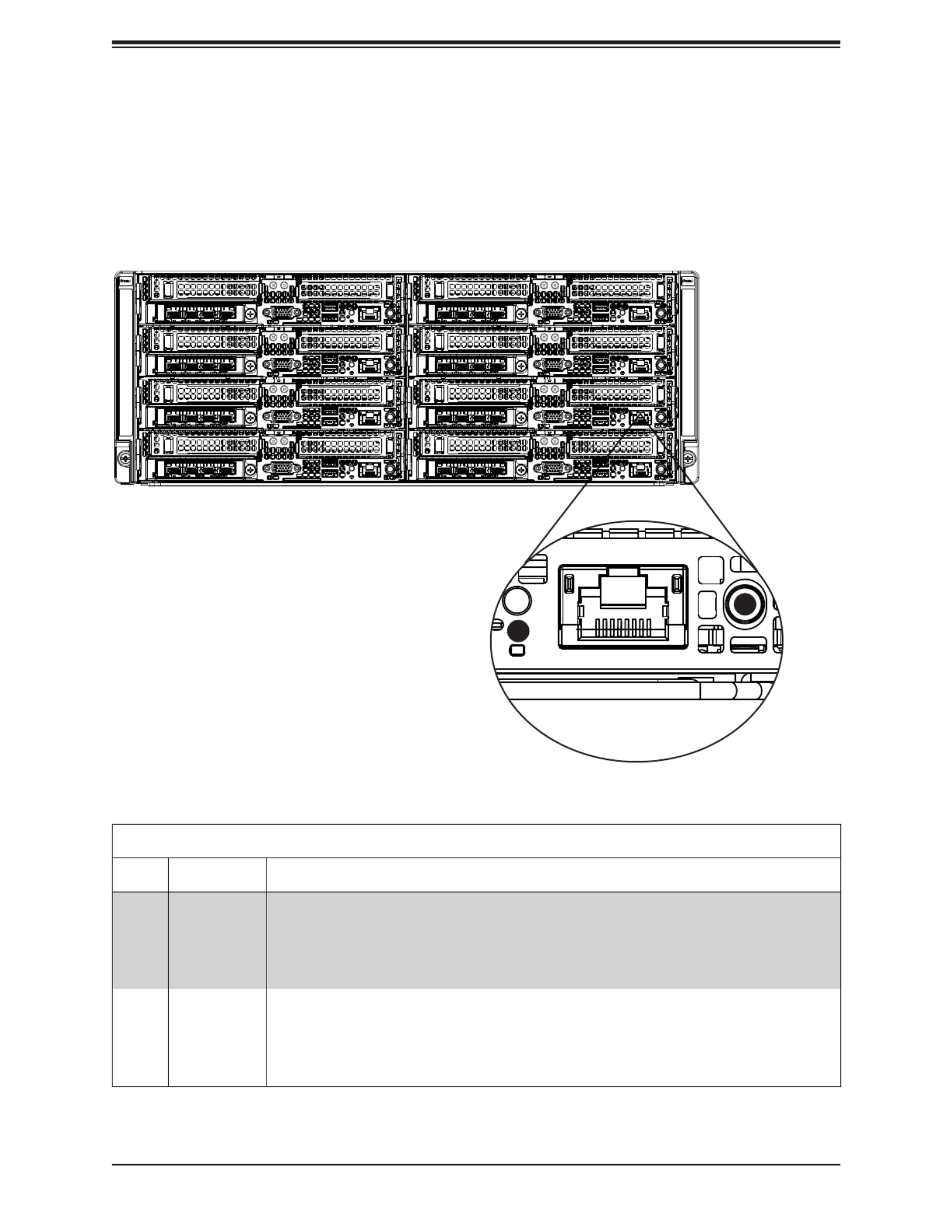
1.5 Server Chassis Features
Node Controls
Each node has a power button and UID LED located with I/O ports on the front of the node.
See Chapter 4 for details on the node controls.
Figure 1-1. Node Controls
1
2

12
FatTwin AS -F1114S-FT User's Manual
Front System Features
Item Feature Description
1 Node Ports and Controls (8) See the section for node controls above for details, and see chapter 4
for node port details.
2 Expansion Card Slots Each node has two bays in the front for low-prole expansion cards.
See chapter 3 for details on the expansion cards.
3 AIOM module See Chapter 4 for details on the SIOM modules.
Figure 1-2. System Front View
1
2
1
1
1
3
3
2
2
2
2
2
2
2
2
2
2
2
2
2
2
2
3
3
3
3
3
3
1
1
1
1
Front Features
The CSE-F418IF4-R2K20BP is a 4U chassis with eight hot-swap server nodes. See the
illustration below for the features included on the front of the chassis.
13
Chapter 1: Introduction
1.6 Motherboard Layout
Below is a layout of the H12SSFF-AN6 with jumper, connector and LED locations shown. See
the table on the following page for descriptions. For detailed descriptions, pinout information
and jumper settings, refer to Chapter 4.
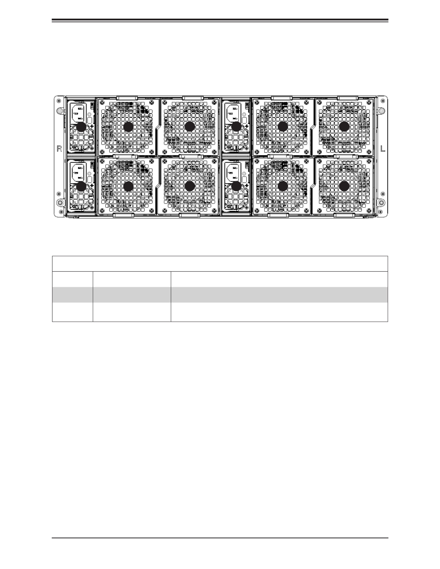
Rear System Features
Item Feature Description
1 Power Supply Four (4) redundant 2200W or 2000W power supplies
2 Rear Fan The chassis has eight rear fans for cooling. These are hot-swappable
and can be replaced without powering down the system.
Figure 1-3. System Rear View
2
2
1
1
12
21
2
2
2
2
Rear Features
The illustration below shows the features included on the rear of the chassis.

15
Chapter 1: Introduction
Note: Jumpers, connectors, switches, and LED indicators that are not described in the
preceding table are for manufacturing testing purposes only and not covered in this manual.
Quick Reference Table
Jumper Description Default Setting
JBT1 Clear CMOS Open (Normal)
JWD1 Watch Dog control Pins 1-2 (Reset)
LED Description Status
LED2 HDD Activity LED Blinking Green: HDD Active
LED3 Overheat/Fan Fail LED Solid Red: OH/Fan Failure
LED4 M.2 LED (for M.2-HC1) Blinking Green: M.2-HC1 Active
LED5 M.2 LED (for M.2-HC2) Blinking Green: M.2-HC2 Active
LEDM1 BMC Heartbeat LED Blinking Green (BMC normal)
UID LED1 Front ID LED Solid blue: UID switched to ON, unit identied
Connector Description
AIOM AIOM slot for networking card
Battery Onboard CMOS battery
DIMMA1 - DIMMH2 DIMM (memory) slots
FAN1, FAN2 System cooling fan headers
HDD_PWR1, HDD_PWR2 HDD/SSD power supply connectors
IPMI_LAN Dedicated IPMI LAN port
I-SATA0 Internal SATA port to support SATA DOM
JCOM1 Onboard COM port header
JIPMB1 4-pin BMC external IC header
JSD1 SATA DOM power connector
JSXB1 PCIe 4.0 x16 connector (for right hand riser card)
JSXB2 PCIe 4.0 x16 connector (for left hand riser card)
JTPM1 Trusted Platform Module (TPM)/Port 80 connector
JUSB1 Front USB 3.0 ports: USB0/USB1
M.2-HC1, M.2-HC2 M.2 PCIe p15-x4 interfaces
NCSI NC-SI connector
P1_NVME1, P1_NVME2 Internal NVMe ports
PB_MISC P12V standby for PMBUS, PS_ON
PB_PWR1, PB_PWR2 P12V
PWR Power on button
SATA0-11 Onboard SATA3 ports
VGA Front VGA port

16
FatTwin AS -F1114S-FT User's Manual
E
CPU
A
DDR4 DIMM
DDR4 DIMM
AMD SP3
PCIE X16
PCIE X4 / SATA
BMC
AST2600
PHY
RTL8211FS
VGA
CPU USB2 [2:3]
TPM/80 Port
BIOS ROM
32MB
LPC
CPU USB2 [0-1]
USB3.0 X2
A1/A2
B
DDR4 DIMM
B1/B2
DDR4 DIMM
C
C1/C2
DDR4 DIMM
D
D1/D2
H
DDR4 DIMM
DDR4 DIMM
G
F
DDR4 DIMM
E1/E2 F1/F2 G1/G2 H1/H2
JSXB1
F I/O
F I/O
RJ45
F I/O
1G-Base
COM
RS-232
BMC ROM
64MB
M.2
S/W
PCIE X4 / SATA
M.2
MINI SAS HD
X3
SLIMSAS L/P
X2
JSXB2 PCIE X16
AIOM PCIE X16
LPC
SATA-DOM
SPI
CPLD
NAND-FLASH
2G-BIT
DUAL-BOOT
4MBIT
NC-SI
S/W
NC-SI CONN.
CPU USB2 [2]
SPI
SPI
SPI
SPI
FANx2
HDD_PWR
X2
SPI1F/W SPI
G1 G0G3 G2
P2 P1P3 P0
G2-SATA[20]
G2-SATA[22]
G2-SATA[23]
G2-SATA[24:27]
G3-SATA[30:33]
G3-SATA[34:37]
G3-PCIE[8]
G3-PCIE[12]
G3-PCIE[9:11]
G3-PCIE[13:15]
G1-PCIE[0:3]
G1-PCIE[4:7]
G1-PCIE[8:11]
G1-PCIE[12:15]
P1-PCIE[0:15]
P0-PCIE[8]
P2-PCIE[0:15]
P3-PCIE[0:15]
Reversal
CPU USB3 [0-1]
Figure 1-5. System on Chip Chipset: System Block Diagram
Note: This is a general block diagram and may not exactly represent the features on your
motherboard. See the System Specications appendix for the actual specications of your
motherboard.

Chapter 2: Server Installation
17
Chapter 2
Server Installation
2.1 Overview
This chapter provides advice and instructions for mounting your system in a server rack.
If your system is not already fully integrated with processors, system memory etc., refer to
Chapter 4 for details on installing those specic components.
Caution: Electrostatic Discharge (ESD) can damage electronic components. To prevent such
damage to PCBs (printed circuit boards), it is important to use a grounded wrist strap, handle
all PCBs by their edges and keep them in anti-static bags when not in use.
2.2 Preparing for Setup
The box in which the system was shipped should include the rackmount hardware needed to
install it into the rack. Please read this section in its entirety before you begin the installation.
Choosing a Setup Location
• The system should be situated in a clean, dust-free area that is well ventilated. Avoid areas
where heat, electrical noise and electromagnetic elds are generated.
• Leave enough clearance in front of the rack so that you can open the front door completely
(~25 inches) and approximately 30 inches of clearance in the back of the rack to allow
sucient space for airow and access when servicing.
• This product should be installed only in a Restricted Access Location (dedicated equipment
rooms, service closets, etc.).
• This product is not suitable for use with visual display workplace devices according to §2
of the German Ordinance for Work with Visual Display Units.
Rack Precautions
• Ensure that the leveling jacks on the bottom of the rack are extended to the oor so that
the full weight of the rack rests on them.

FatTwin AS -F1114S-FT User's Manual
18
• In single rack installations, stabilizers should be attached to the rack. In multiple rack in-
stallations, the racks should be coupled together.
• Always make sure the rack is stable before extending a server or other component from
the rack.
• You should extend only one server or component at a time - extending two or more simul-
taneously may cause the rack to become unstable.
Server Precautions
• Review the electrical and general safety precautions in Appendix B.
• Determine the placement of each component in the rack you install the rails.before
• Install the heaviest server components at the bottom of the rack rst and then work your
way up.
• Use a regulating uninterruptible power supply (UPS) to protect the server from power
surges and voltage spikes and to keep your system operating in case of a power failure.
• Allow any drives and power supply modules to cool before touching them.
• When not servicing, always keep the front door of the rack and all covers/panels on the
servers closed to maintain proper cooling.
Rack Mounting Considerations
Ambient Operating Temperature
If installed in a closed or multi-unit rack assembly, the ambient operating temperature of
the rack environment may be greater than the room's ambient temperature. Therefore,
consideration should be given to installing the equipment in an environment compatible with
the manufacturer’s maximum rated ambient temperature (TMRA).
Airow
Equipment should be mounted into a rack so that the amount of airow required for safe
operation is not compromised.
Mechanical Loading
Equipment should be mounted into a rack so that a hazardous condition does not arise due
to uneven mechanical loading.

Chapter 2: Server Installation
19
Note: Insert the nodes into the chassis from the bottom left to bottom right and then up all
the way to the top (left rst, then right). Do not insert the nodes on one side fully (leaving one
side empty) and then the other side or it will be very hard to insert the last node.
Circuit Overloading
Consideration should be given to the connection of the equipment to the power supply circuitry
and the eect that any possible overloading of circuits might have on overcurrent protection
and power supply wiring. Appropriate consideration of equipment nameplate ratings should
be used when addressing this concern.
Reliable Ground
A reliable ground must be maintained at all times. To ensure this, the rack itself should be
grounded. Particular attention should be given to power supply connections other than the
direct connections to the branch circuit (i.e. the use of power strips, etc.).
To prevent bodily injury when mounting or servicing this unit in a rack, you must take
special precautions to ensure that the system remains stable. The following guidelines
are provided to ensure your safety:
• This unit should be mounted at the bottom of the rack if it is the only unit in the rack.
• When mounting this unit in a partially lled rack, load the rack from the bottom to the top
with the heaviest component at the bottom of the rack.
• If the rack is provided with stabilizing devices, install the stabilizers before mounting or
servicing the unit in the rack.

FatTwin AS -F1114S-FT User's Manual
20
2.3 Rack Mounting Instructions
This section provides information on installing the chassis into a rack unit with the rails
provided. There are a variety of rack units on the market, which may mean that the assembly
procedure will dier slightly from the instructions provided. You should also refer to the
installation instructions that came with the rack unit you are using.
Note: This rail will t a rack between 28" and 33.5" deep. The CSE-F418IF4 is not designed
for installation into a Telco post-style rack unit.
Stability Hazard: The rack stabilizing mechanism must be in place, or the rack must
be bolted to the oor before you slide the unit out for servicing. Failure to stabilize the
rack can cause the rack to tip over.
Warning: Slide rail mounted equipment is not to be used as a shelf or a work space.
Warning: When initially installing the server to a rack, test that the rail locking tabs engage to
prevent the server from being overextended. Have a rack lift in place as a precaution in case
the test fails.
Warning: In any instance of pulling the system from the rack, always use a rack lift and follow
all associated safety precautions.
Chapter 2: Server Installation
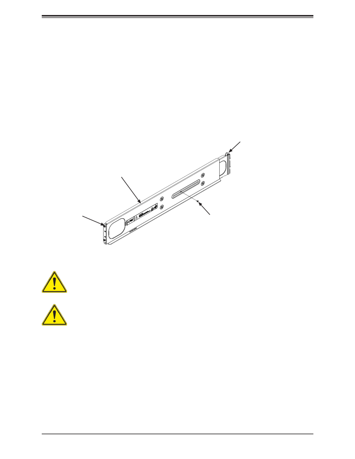
21
Figure 2-1. Identifying the Rail Sections
Warning: do not pick up the server with the front handles. They are designed to pull
the system from a rack only.
Slide rail mounted equipment is not to be used as a shelf or a work space.
Identifying the Sections of the Rack Rails
The chassis package includes two rail assemblies in the rack mounting kit. Each assembly
consists of two sections: A front section which secures to the front post of the rack and a rear
section which adjusts in length and secures to the rear post of the rack. These assemblies
are specically designed for the left and right side of the chassis (see Figure 2-1).
Adjusting the Rails
Each rail assembly has an adjusting screw. loosening this screw allows you to adjust the
length of the rail to t a variety of rack sizes.
Inner Rail
This Side Faces
Outward Adjusting Screw
Outer Rail

FatTwin AS -F1114S-FT User's Manual
22
Figure 2-2. Attaching the Rails to a Rack
Installing the Rails on a Rack
Installing the Rails
1. Adjust the length of both rails as described on the previous page.
2. Align the front section of the outer rail with the slots on the front post of the rack. Secure
the front of the outer rail to the rack with two screws.
3. Pull out the rear section of the outer rail, adjusting the length until it ts within the posts
of the rack.
4. Align the rear section of the rail with the slots on the rear post of the rack. Secure the
rear of the outer rail to the rear of the rack with two screws.
5. Repeat steps 1-4 for the remaining rail.
FRONT BACK

Chapter 2: Server Installation
23
Note: The gure above is for illustration purposes only and does not represent exactly the
same server in this manual. Always install servers to the bottom of the rack rst.
Figure 2-3. Installing into a Rack
Chassis Installation
Installing the Chassis into a Rack
1. Conrm that the rails are correctly installed on the rack.
2. Align the bottom of the chassis with the bottom of the rails.
3. Insert the chassis into the AS -F1114S-FT rails, keeping the pressure even on both
sides, pushing the chassis into the rack until it clicks into the locked position.
4. Secure the chassis handles to the front of the rack.

FatTwin AS -F1114S-FT User's Manual
24
Chapter 3
Maintenance and Component Installation
This chapter provides instructions on installing and replacing main system components. To
prevent compatibility issues, only use components that match the specications and/or part
numbers given.
Installation or replacement of most components require that power rst be removed from the
system. Please follow the procedures given in each section.
3.1 Removing Power
Use the following procedure to ensure that power has been removed from the system. This
step is necessary when removing or installing non hot-swap components or when replacing
a non-redundant power supply.
Removing the Power Cord
1. Use the operating system to power down the system, following the on-screen prompts.
2. After the system has completely shut-down, carefully grasp the head of the power cord
and gently pull it out of the back of the power supply.
3. If your system has dual redundant power supplies, remove the cords from both power
supplies.
4. Disconnect the cord from the power strip or wall outlet.

25
Chapter 3: Maintenance and Component Installation
3.2 Chassis Components
The chassis includes power supplies, fans and eight nodes. Each node is a separate system
containing a drawer with a serverboard and other components. Each node may be removed
from the chassis separately.
Installing and Removing the Node Drawers
The CSE-F418IF4 chassis contains eight individual motherboards in separate node drawers
(Figure 3-1). Each motherboard node controls a set of two internal xed hard drives. Note
that if a motherboard node drawer is pulled out of the chassis, the hard drives associated
with that node will power down as well.
Figure 3-1. Installing and Removing the Node Drawers
Node 4
Node 8
Node 3
Node 7
Node 6
Node 5
Node 2
Node 1
FatTwin AS -F1114S-FT User's Manual
26
Removing Nodes from the Chassis
Each of the eight individual nodes may be removed from the chassis separately. Note that
when a node is removed from the chassis, the hard drives located in the node will shut-down.
Removing a Node
1. Grasp the node by the handles on both sides of the front of the node.
2. Press down on the left handle to disengage the latch.
3. While holding down the left handle, carefully pull the node forward and out of the
chassis.
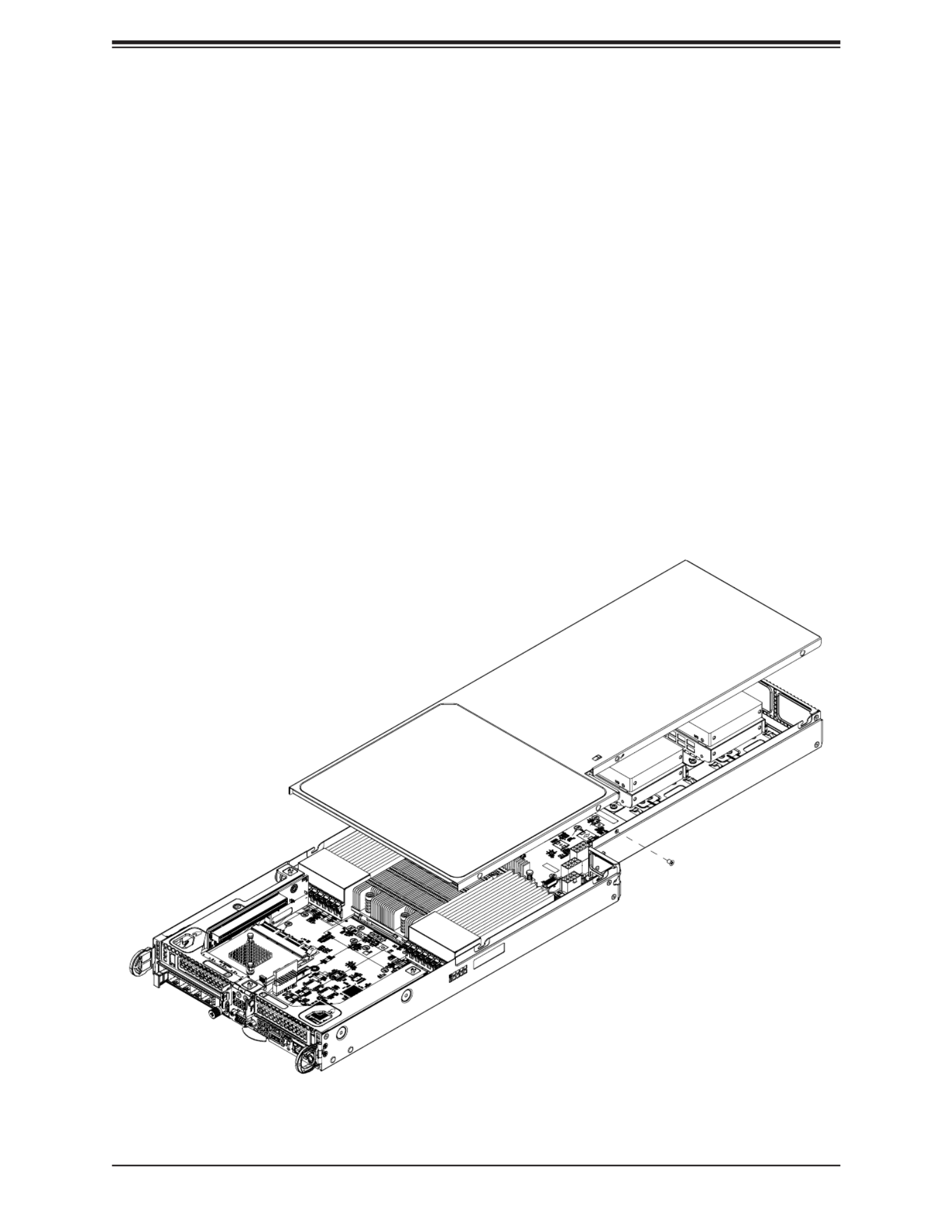
Removing the Cover from the Node
Removing the Node Cover
1. Remove the node from the chassis as described above.
2. Push the top cover toward the rear side of the node.
3. Lift the cover up and o the node.
Figure 3-2. Removing the Node Cover

27
Chapter 3: Maintenance and Component Installation
Nodes and Associated Hard Drives
The CSE-F418IF4 chassis contains up to eight individual motherboards in separate 1U nodes.
Each node has either two 2.5" drives, with an additional optional two 2.5" drives for the P2
model. Zero nodes have eight drives. Note that if a node is pulled out of the chassis, the hard
drives associated with that node will power down as well. Refer to the charts below and on
the following pages for your specic chassis conguration
Installing and Removing 2.5" Hard Drives
Removing 2.5" Fixed Hard Drives from the Node
1. Remove the node from the chassis and remove the cover from the node as described
previously in this section.
2. Remove the screw securing the hard drive tray to the oor of the chassis.
3. Lift the hard drive and tray up and out of the chassis.
Figure 3-3. Removing 2.5" Fixed Hard Drives from a Node
3

29
Chapter 3: Maintenance and Component Installation
Installing Expansion Cards
Each of the eight nodes in the chassis has space for two low-prole expansion cards mounted
in the front of the node. The following instructions are for chassis nodes in which the expansion
cards are mounted in the front of the node.
Figure 3-6. PCIe Slot Conguration
PCIe Slot Shield
PCIe Slot Clip

FatTwin AS -F1114S-FT User's Manual
30
Figure 3-7. Assembling the PCIe Slot Bracket and Riser Card
Assembling the PCIe Slot Bracket Assembly
Each node supports two expansion cards in front of the node. Each expansion card must be
plugged into a riser card, which in turn plugs into the motherboard.
Assembling the PCIe Slot Bracket Assembly
1. Remove the node from the chassis and remove the cover from the node as described
previously in this section.
2. Open the PCIe slot clip and remove the PCIe slot shield. (See the illustration on the
previous page)
3. Remove the tool-less PCIe slot bracket.
4. Lift the PCIe slot bracket out of the node.
Expansion Card
PCIe Slot Bracket
Card Mounting
Screws

FatTwin AS -F1114S-FT User's Manual
32
Installing Air Shrouds
Air Shrouds
Air shrouds concentrate airow to maximize fan eciency. The CSE-F418IF4 chassis require
an air shroud in each node.
Installing an Air Shroud
1. Remove the node from the chassis and remove the cover from the node as described
previously in this section.
2. Make sure that the motherboard and all components are properly installed in each node.
3. Place the two air shrouds over the motherboard, as illustrated below.
4. Repeat the procedure for the remaining nodes.
Figure 3-9. Installing the Air Shroud

33
Chapter 3: Maintenance and Component Installation
Removing and Installing System Fans
Removing and Installing External System Fans
The chassis has eight fans in the rear of the system. Fans that fail can be replaced by simply
removing them from the rear without powering down the system.
Removing a Rear Exhaust Fan
1. Determine which fan has failed.
2. Press the release tabs on the fan and pull it away from rear of the system.
Installing a Rear Exhaust Fan
1. Press the release tabs on the fan and insert it into the open fan bay.
2. Push the fan into the bay until it clicks into the locked position.
Figure 3-10. Installing the External Fan
FatTwin AS -F1114S-FT User's Manual
34
Replacing the Power Supplies
The CSE-F418IF4 chassis includes four redundant 2200W or 2000W power supplies. These
power supplies are auto-switching capable. This enables the power supplies to automatically
sense and operate at a 100v to 240v input voltage. An amber light will be illuminated on
the power supply when the power is o. An illuminated green light indicates that the power
supply is operating.
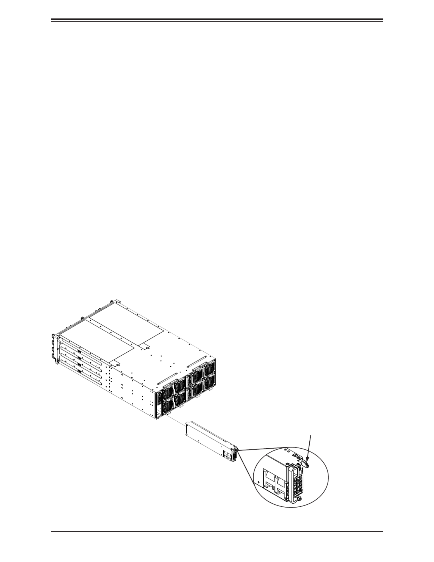
Power Supply Replacement
The CSE-F418IF4 chassis utilizes redundant power supplies. In the unlikely event that the
power supply unit needs to be replaced, a power supply can be removed, without powering
down the system. Replacement units can be ordered directly from Supermicro (See the
contact information in the Preface of this manual).
Changing the Power Supply
1. Disconnect the AC power cord on the back of the failed power supply.
2. Press the release tab on the back of the power supply and pull the power supply out
using the handle provided.
3. Push the replacement power supply module into the power bay until it clicks into the
locked position.
4. Plug the AC power cord back into the power supply module and power it up.
Figure 3-11. Changing a Power Supply
Release Tab

35
Chapter 3: Maintenance and Component Installation
3.3 Motherboard Components
Processor and Heatsink Installation
Warning: When handling the processor package, avoid placing direct pressure on the label
area of the fan. Also, improper CPU installation or socket misalignment can cause serious
damage to the CPU or the motherboard that will require RMA repairs. Please read and follow
all instructions thoroughly before installing your CPU and heatsink.
Important:
• For the Processor/Heatsink installation you need to use a T20 screwdriver when opening/
closing the CPU socket.
• Always connect the power cord last, and always remove it before adding, removing or
changing any hardware components. Make sure that you install the processor into the
CPU socket before you install the CPU heatsink.
• If you buy a CPU separately, make sure that you use an AMD-certied multi-directional
heatsink only.
• Make sure to install the motherboard into the chassis before you install the CPU heatsink.
• When receiving a motherboard without a processor pre-installed, make sure that the plastic
CPU socket cap is in place and none of the socket pins are bent; otherwise, contact your
retailer immediately.
• Refer to the Supermicro website for updates on CPU support.

FatTwin AS -F1114S-FT User's Manual
36
Installing the Processor and Heatsink
1. Unscrew the screws holding down Force Frame in the sequence of 3-2-1. The screws
are numbered on the Force Frame next to each screw hole.
Screw #1
Screw #2
Screw #3
Force Frame
2. The spring-loaded Force Frame will raise up after the last screw securing it (#1) is
removed. Gently allow it to lift up to its stopping position.
Produkt Specifikationer
| Mærke: | Supermicro |
| Kategori: | Server |
| Model: | A+ Server F1114S-FT |
Har du brug for hjælp?
Hvis du har brug for hjælp til Supermicro A+ Server F1114S-FT stil et spørgsmål nedenfor, og andre brugere vil svare dig
Server Supermicro Manualer

30 Januar 2025
30 Januar 2025
11 Januar 2025
11 Januar 2025
11 Januar 2025
8 Januar 2025
28 December 2024
28 December 2024
28 December 2024
28 December 2024
Server Manualer
- Server QNAP
- Server Bosch
- Server Acer
- Server Sony
- Server HP
- Server D-Link
- Server Asus
- Server Gigabyte
- Server Toshiba
- Server Lenovo
- Server Abus
- Server Planet
- Server Black Box
- Server TRENDnet
- Server Buffalo
- Server Medion
- Server Linksys
- Server Megasat
- Server Cisco
- Server Seagate
- Server Netgear
- Server Tripp Lite
- Server Western Digital
- Server Technics
- Server Digitus
- Server Dell
- Server Fujitsu
- Server MSI
- Server NEC
- Server APC
- Server LevelOne
- Server FLIR
- Server ZyXEL
- Server Eaton
- Server ELAC
- Server Synology
- Server Hikvision
- Server Monacor
- Server AVerMedia
- Server Asustor
- Server Kramer
- Server Hanwha
- Server LaCie
- Server Naim
- Server Fantec
- Server Provision-ISR
- Server Quantum
- Server Axis
- Server ACTi
- Server Digi
- Server ATen
- Server Teo
- Server Vimar
- Server Smart-AVI
- Server Intel
- Server StarTech.com
- Server Conceptronic
- Server Rocstor
- Server IStarUSA
- Server Blackmagic Design
- Server Lindy
- Server Veritas
- Server Promise Technology
- Server Sitecom
- Server HGST
- Server AMX
- Server Intellinet
- Server Iomega
- Server Silverstone
- Server Geovision
- Server Ernitec
- Server KanexPro
- Server Gefen
- Server Moxa
- Server C2G
- Server Allnet
- Server Maxdata
- Server Matrox
- Server Valcom
- Server Freecom
- Server IoSafe
- Server Revox
- Server Luxman
- Server G-Technology
- Server Areca
- Server SEH
- Server Ibm
- Server Sonnet
- Server TAIDEN
- Server SIIG
- Server Advantech
- Server Mobotix
- Server Extron
- Server Avocent
- Server Silex
- Server Middle Atlantic
- Server In Win
- Server Sun
- Server Atlona
- Server MvixUSA
- Server Dual Bay
- Server Raidsonic
- Server EMC
- Server Infortrend
- Server Opengear
- Server EXSYS
- Server Raritan
- Server Chenbro Micom
- Server Mr. Signal
- Server Atlantis Land
- Server Lantronix
- Server NETSCOUT
- Server Origin Storage
- Server IMC Networks
Nyeste Server Manualer

9 Marts 2025
9 Marts 2025
9 Marts 2025
23 Januar 2025
23 Januar 2025
23 Januar 2025
23 Januar 2025
23 Januar 2025
19 Januar 2025
14 Januar 2025