TP-Link N600 Manual
TP-Link
Adgangspunkt
N600
Læs nedenfor 📖 manual på dansk for TP-Link N600 (20 sider) i kategorien Adgangspunkt. Denne guide var nyttig for 17 personer og blev bedømt med 4.5 stjerner i gennemsnit af 2 brugere
Side 1/20

Installation Guide
Wireless N Access Point
EAP110/EAP120/EAP220


CONTENTS
About This Installation Guide
This guide is designed to familiarize you with the general layout of the EAP110,
EAP120 and EAP220, describe how to perform the hardware installation, and how
to configure the EAP Controller software in your network. Your EAP has more
features and functionalities which can be found in the User Guide.
Conventions
Unless otherwise noted, the EAP or the device mentioned in this guide stands for
300Mbps Wireless N Access Point EAP110, Wireless N Gigabit Access Point EAP120
and EAP220.
Network Topology 01 —————————————————————
Hardware Overview 02 ————————————————————
Hardware Installation ——————————————————— 05
1. Installation Requirements ....................................................... 05
2. Mounting Bracket ................................................................... 05
3. Installation ............................................................................ 06
4. Power Supply ......................................................................... 11
Software Conguration —————————————————— 13
Q&A 14 ———————————————————————————
Specications ——————————————————————— 15
01
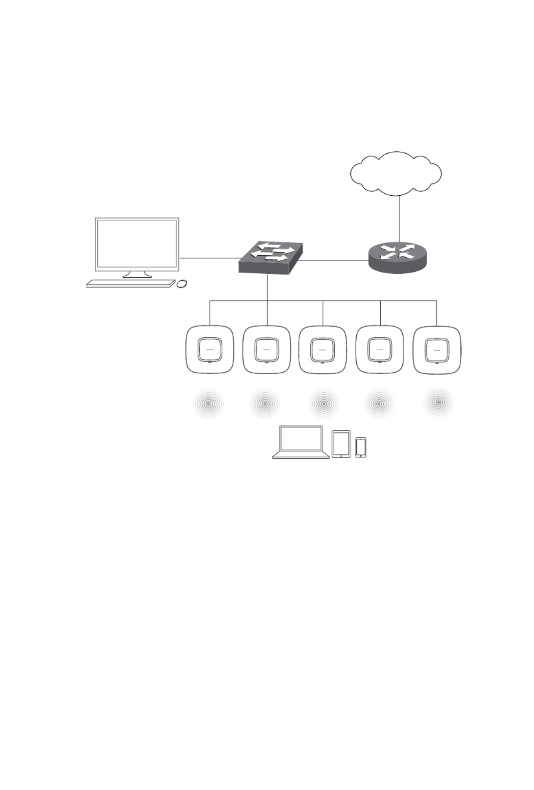
Network Topology
A typical network topology for the EAP is shown below.
Controller Host
EAP
Controller
Router
Switch
Internet
EAP
Clients
To deploy an EAP in your local network, a DHCP server is required to assign IP
addresses to the EAP and clients. Typically, a router acts as the DHCP server.
Ensure the EAPs are in the same subnet with the Controller Host in which the EAP
Controller software is installed.
The EAP can be managed by the EAP Controller software, which is a management
software specially designed for the TP-LINK EAP devices on a local wireless
network, allowing you to centrally configure and monitor mass EAP devices using
a web browser on your PC. The EAP can also work independently as a standalone
device.
02
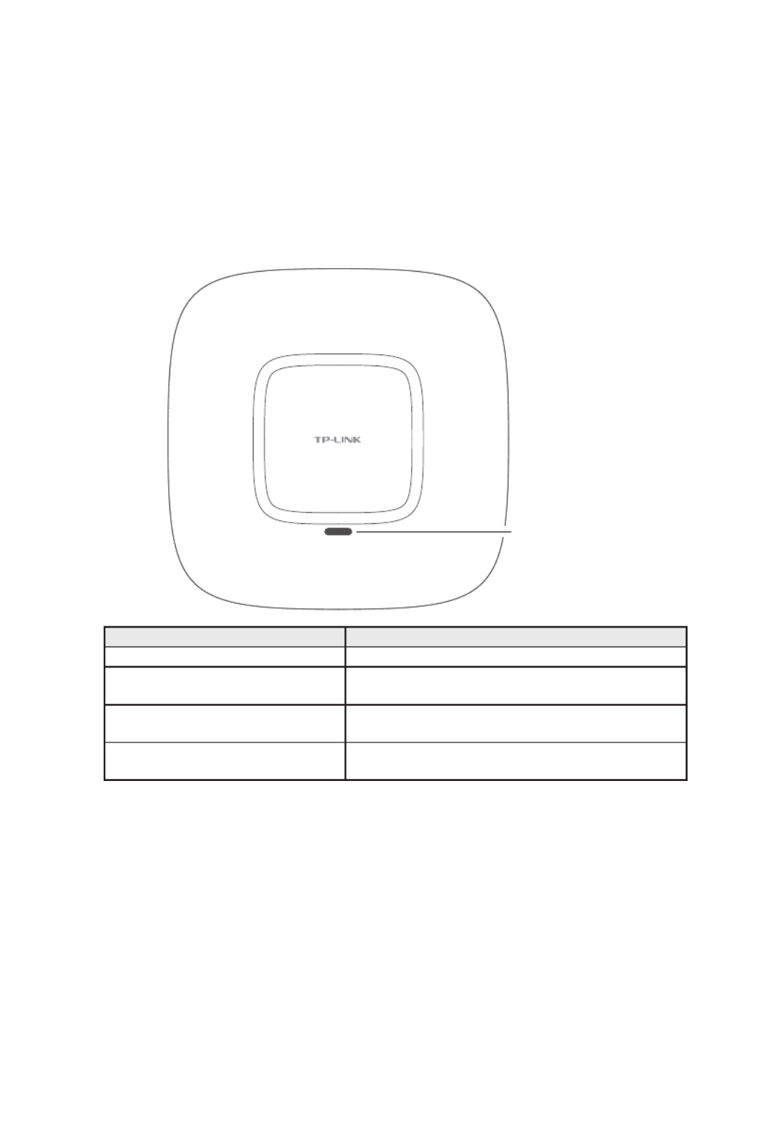
Hardware Overview
1. LED
EAP110, EAP120 and EAP220 have the same LED status and corresponding
indications.
System LED
LED Status Indication
Solid green The device is working properly.
Flashing red System errors. RAM, Flash, Ethernet, WLAN or
firmware may be malfunctioning.
Flashing yellow Firmware update is in progress. Do not disconnect
or power off the device.
Double-flashing red, green, yellow The device is being reset to its factory default
settings.

03
2. Interface Panel
■EAP110
ARROW 1
RESET ETHERNET
■EAP120/EAP220
ARROW 1
RESET CONSOLE ETHERNET ON/OFF POWER
Please note that EAP110 does not have the CONSOLE port, POWER port or ON/OFF
button. The interface panel components of the EAP, from left to right, are described
in the following list.
Kensington Security Slot
Secure the lock (not provided) into the security slot to prevent the device from
being stolen.
RESET
With the device powered on, press and hold the RESET button for about 8 seconds
until the LED ashes red, then release the button. The device will restore to factory
default settings.
CONSOLE
This port is used to connect to the serial port of a computer or a terminal to check
and monitor system information of EAP120/EAP220.
Note: CLI commands are not available in current software version. We will release
a new version supporting CLI commands soon. Please pay close attention to our
ofcial website.

04
ON/OFF
Press this button to turn on/off the EAP120/EAP220.
POWER
The power port is used to connect the EAP120/EAP220 to an electrical wall outlet
via power adapter. Please only use the provided power adapter. Refer to next
chapter 4.Power Supply to learn how to power the EAP120/EAP220 via power
adapter.
ARROW 1
This arrow is used to align with ARROW 2 on the mounting bracket to lock the EAP
into place. Please refer to next chapter to locate ARROW 2. 2.Mounting Bracket
ETHERNET
For EAP110, this port is used to connect to the POE port of the provided PoE
adapter for both data transmission and power supply through Ethernet cabling.
For EAP120/EAP220, this port is used to connect to a router or a switch to transmit
data or to a PSE (Power Sourcing Equipment), such as a PoE switch, for both data
transmission and Power over Ethernet (PoE) through Ethernet cabling.
■Passive PoE Adapter
The PoE adapter is ONLY provided with EAP110 for power supply. Refer to next
chapter 4.Power Supply to learn more about power supply for EAP110.
Power LED
Power LED
The Power LED indicates the status of the electric current: green (0-0.8A), red
(0.8A-1A).
POE Port
This port is used to connect to the ETHERNET port of EAP110.
LAN Port
This port is used to connect to your LAN.
05
Hardware Installation
The EAP can be wall-mounted or ceiling-mounted. Please suitably arrange your
wire layout before mounting the EAP. We take EAP110 as example to explain the
installation. EAP110 can be powered via the provided PoE adapter, while EAP120
and EAP220 can be powered via a PoE switch or the provided power adapter.
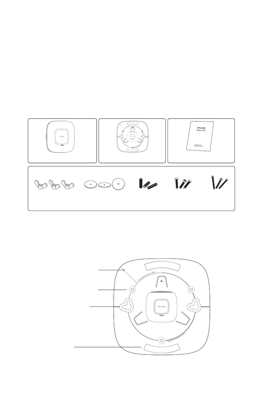
1. Installation Requirements
Before installation, check the package contents for the following items:
Other installation equipments may require, including a pencil, ruler, drill, drill bit,
screwdriver and a ladder.
2. Mounting Bracket
The following figure describes the layout of the mounting bracket.
Locking clip
ARROW 2 is used to align
with ARROW 1 under the
interface panel
Ceiling mounting slot
Wall mounting slot
EAP Mounting Bracket Installation Guide
Wing Nuts (3) Washers (3) Plastic Wall
Anchors (3)
Self-tapping
Screws (3)
Pan-head
Screws (3)

06
3. Installation
■Ceiling Mounting
Note:
■Make sure the thickness of the ceiling is less than 18mm and
the ceiling can bear at least five kilograms.
■It is NOT recommended to mount the EAP on a low-strength
material, such as gypsum ceiling panel. If no other choice is
available, make sure you add a piece of strong material under
the wing nuts to ensure the EAP is mounted solidly.
1. Remove the ceiling tile.
2. Place the mounting bracket in the center of the ceiling tile. Mark the positions
of the three mounting slots and a hole for the Ethernet cable to feed through.
L≈40mm
L
Mark of the hole for Ethernet
cable to feed through

07
3. Use a drill with the appropriate size drill bit to drill three 4mm holes for
the pan-head screws, and drill a 10mm hole for the Ethernet cable to feed
through.
10mm hole for Ethernet cable feed
4mm hole for mounting bracket
4. Secure the mounting bracket to the ceiling tile using the pan-head screws,
washers and wing nuts, as shown below.
Hole to feed the Ethernet cable
Hole to feed the screw
Pan-head screw
Wing nut
Washer
Produkt Specifikationer
| Mærke: | TP-Link |
| Kategori: | Adgangspunkt |
| Model: | N600 |
| Bredde: | 86.5 mm |
| Dybde: | 24 mm |
| Højde: | 10 mm |
| Produktfarve: | Hvid |
| Wi-Fi: | Ja |
| Opbevaringstemperatur (T-T): | -40 - 70 °C |
| Relativ luftfugtighed ved drift (H-H): | 10 - 90 % |
| Relativ luftfugtighed ved opbevaring (H-H): | 5 - 90 % |
| Wi-Fi-standarder: | 802.11a,802.11b,802.11g |
| Driftstemperatur (T-T): | 0 - 40 °C |
| Sikkerhedsalgoritmer: | 128-bit WEP,64-bit WEP,802.1x RADIUS,WPA-PSK,WPA2-PSK |
| Hurtig start guide: | Ja |
| Forbindelsesteknologi: | Trådløs |
| Certificering: | CE, FCC |
| Bedste Wi-Fi standard: | Wi-Fi 4 (802.11n) |
| Netværksstandarder: | IEEE 802.11a,IEEE 802.11b,IEEE 802.11g,IEEE 802.11n |
| Trådløs forbindelse: | Ja |
| Bæredygtighedscertifikater: | RoHS |
| Understøttede Windows-operativsystemer: | Ja |
| Værtsgrænseflade: | USB |
| Grænseflade: | WLAN |
| Intern: | Ingen |
| Maksimal dataoverførselshastighed: | 300 Mbit/s |
| Understøttede WLAN-dataoverførselshastigheder: | 11,54,300 Mbit/s |
| Modulation: | 16-QAM,64-QAM,CCK,DBPSK,DQPSK,OFDM |
| Minimum systemkrav: | Windows 7(32/64bits), Windows Vista(32/64bits), Windows XP(32/64bits) |
| Optisk drev påkrævet: | Ja |
Har du brug for hjælp?
Hvis du har brug for hjælp til TP-Link N600 stil et spørgsmål nedenfor, og andre brugere vil svare dig
Adgangspunkt TP-Link Manualer

30 December 2025
11 December 2024
4 December 2024
3 Oktober 2024
1 Oktober 2024
11 September 2024
10 September 2024
10 September 2024
2 September 2024
2 September 2024
Adgangspunkt Manualer
- Adgangspunkt Bosch
- Adgangspunkt Aruba
- Adgangspunkt Netis
- Adgangspunkt Moog
- Adgangspunkt HP
- Adgangspunkt D-Link
- Adgangspunkt Asus
- Adgangspunkt AVM
- Adgangspunkt Planet
- Adgangspunkt Belkin
- Adgangspunkt Edimax
- Adgangspunkt Black Box
- Adgangspunkt DataVideo
- Adgangspunkt TRENDnet
- Adgangspunkt Honeywell
- Adgangspunkt Buffalo
- Adgangspunkt Linksys
- Adgangspunkt Cisco
- Adgangspunkt Huawei
- Adgangspunkt Netgear
- Adgangspunkt Totolink
- Adgangspunkt Digitus
- Adgangspunkt Zebra
- Adgangspunkt Techly
- Adgangspunkt Dell
- Adgangspunkt Alcatel-Lucent
- Adgangspunkt LevelOne
- Adgangspunkt ZyXEL
- Adgangspunkt Fortinet
- Adgangspunkt Tenda
- Adgangspunkt LigoWave
- Adgangspunkt EQ3
- Adgangspunkt Ubiquiti Networks
- Adgangspunkt EnGenius
- Adgangspunkt Devolo
- Adgangspunkt Grandstream
- Adgangspunkt Renkforce
- Adgangspunkt Mikrotik
- Adgangspunkt Eminent
- Adgangspunkt Hercules
- Adgangspunkt V7
- Adgangspunkt Amer Networks
- Adgangspunkt Mercku
- Adgangspunkt EQ-3
- Adgangspunkt Vimar
- Adgangspunkt Dahua Technology
- Adgangspunkt Speco Technologies
- Adgangspunkt StarTech.com
- Adgangspunkt Draytek
- Adgangspunkt Crestron
- Adgangspunkt Lindy
- Adgangspunkt Lancom
- Adgangspunkt Sitecom
- Adgangspunkt AMX
- Adgangspunkt Homematic IP
- Adgangspunkt Intellinet
- Adgangspunkt Kingston
- Adgangspunkt Steren
- Adgangspunkt Media-Tech
- Adgangspunkt Moxa
- Adgangspunkt Allnet
- Adgangspunkt Allied Telesis
- Adgangspunkt Airlive
- Adgangspunkt Macally
- Adgangspunkt Hawking Technologies
- Adgangspunkt INCA
- Adgangspunkt Advantech
- Adgangspunkt Silex
- Adgangspunkt SMC
- Adgangspunkt Cambium Networks
- Adgangspunkt CradlePoint
- Adgangspunkt FlyingVoice
- Adgangspunkt Extreme Networks
- Adgangspunkt Aerohive
- Adgangspunkt Bountiful
- Adgangspunkt WatchGuard
- Adgangspunkt NUVO
- Adgangspunkt Cudy
- Adgangspunkt IP-COM
- Adgangspunkt Mach Power
- Adgangspunkt Syscom
- Adgangspunkt Meru
- Adgangspunkt Amped Wireless
- Adgangspunkt 3Com
- Adgangspunkt Ruckus Wireless
- Adgangspunkt Bintec-elmeg
- Adgangspunkt Brocade
- Adgangspunkt ICC
- Adgangspunkt Insteon
- Adgangspunkt Juniper
- Adgangspunkt Comtrend
- Adgangspunkt Premiertek
- Adgangspunkt Atlantis Land
- Adgangspunkt Mojo
- Adgangspunkt Luxul
- Adgangspunkt Peplink
Nyeste Adgangspunkt Manualer
5 April 2025
20 Marts 2025

15 Januar 2025
13 Januar 2025
13 Januar 2025
13 Januar 2025
12 Januar 2025

26 December 2024
23 December 2024
23 December 2024