Trix 22014 Manual
Læs gratis den danske manual til Trix 22014 (84 sider) i kategorien Modelbygning. Denne vejledning er vurderet som hjælpsom af 11 personer og har en gennemsnitlig bedømmelse på 3.5 stjerner ud af 6 anmeldelser.
Har du et spørgsmål om Trix 22014, eller vil du spørge andre brugere om produktet?
Produkt Specifikationer
| Mærke: | Trix |
| Kategori: | Modelbygning |
| Model: | 22014 |
| Type: | Model Railways Parts & Accessories |
| Bredde: | - mm |
| Dybde: | - mm |
| Højde: | - mm |
| Vægt: | HO (1:87) |
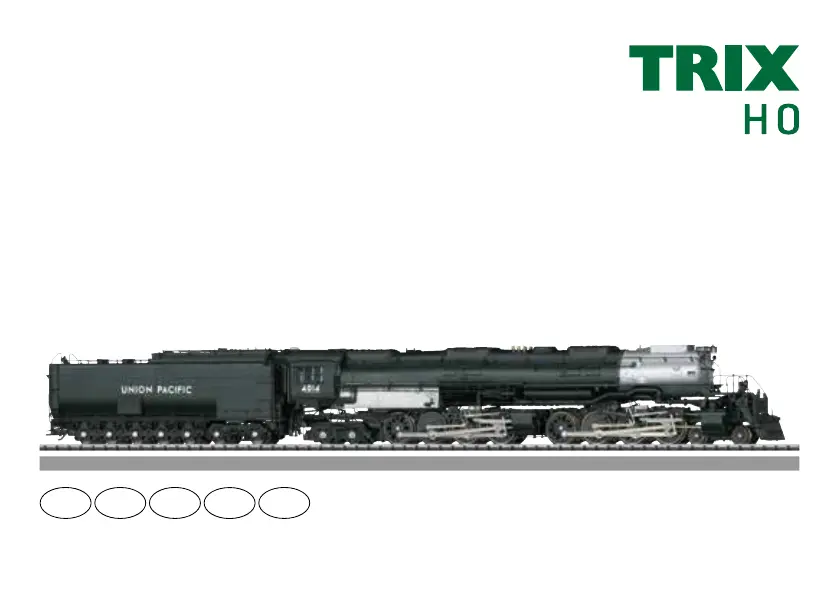
| Produktfarve: | Sort, sølv |
| Produkttype: | Lokomotiv |
| Længde: | 465 mm |
| Anbefalet alder (min.): | 15 År |
| Mærke kompatibilitet: | Trix |
| Foreslået køn: | Dreng |
| Klingende: | Ja |
| Ikke for børn fra 0-3 år: | Ja |
| Radius: | 360 mm |
Har du brug for hjælp?
Hvis du har brug for hjælp til Trix 22014 stil et spørgsmål nedenfor, og andre brugere vil svare dig
Modelbygning Trix Manualer


Modelbygning Manualer
- Siku
- Playmobil
- Roco
- KidKraft
- Geomag
- Robbe
- Thames & Kosmos
- Discovery
- Hitec
- MBZ
- Graupner
- Wiking
- Wilesco
- Snap Circuits
- Carson
Nyeste Modelbygning Manualer


