Allied Telesis AT-9724TS Manual
Allied Telesis
Diverse - Andet
AT-9724TS
Læs nedenfor 📖 manual på dansk for Allied Telesis AT-9724TS (197 sider) i kategorien Diverse - Andet. Denne guide var nyttig for 25 personer og blev bedømt med 4.5 stjerner i gennemsnit af 2 brugere
Side 1/197

High-Density Layer 3 Stackable Gigabit Ethernet Switch
AT-9724TS
Installation and User’s Guide
PN D617/10032 Rev 1
Copyright. 2004 Allied Telesyn, Inc.
19800 North Creek Parkway, Suite 200, Bothell WA 98011, USA
All rights reserved. No part of this publication may be reproduced without prior written permission from Allied Telesyn,
Inc.All product names, company names, logos or other designations mentioned herein are trademarks or registered trademarks
of their respective owners.Allied Telesyn, Inc. reserves the right to make changes in specifications and other information
contained in this document without prior written notice.The information provided herein is subject to change
without notice. In no event shall Allied Telesyn Inc. be liable for any incidental, special, indirect, or consequential damages
whatsoever, including but not limited to lost profits, arising out of or related to this manual or the information contained
herein, even if Allied Telesyn, Inc. has been advised of, known, or should have known, the possibility of such damages.

Electrical Safety and Emission Statement
Standards:This product meets the following standards.
CE Marking Warning: This is a Class A product. In a domestic environment this product may cause radio interference in which case the user may be required to take adequate
measures.
Important: Appendix B contains translated safety statements for installing this equipment.When you see the go to Appendix A for the translated safety statement in your language.
Wichtig: Anhang B enthält übersetzte Sicherheitshinweise für die Installation dieses Geräts.Wenn Sie sehen, schlagen Sie in Anhang A den übersetzten Sicherheitshinweis in Ihrer
Sprache nach.
Vigtigt: Tillæg B indeholder oversatte sikkerhedsadvarsler, der vedrører installation af dette udstyr. Når De ser symbolet, skal De slå op i tillæg A og finde de oversatte
sikkerhedsadvarsler i Deres eget sprog.
Belangrijk: Appendix B bevat vertaalde veiligheidsopmerkingen voor het installeren van deze apparatuur.Wanneer u de ziet, raadpleeg Appendix A voor vertaalde v
eiligheidsinstructies in uw taal.
Important: L'annexe B contient les instructions de sécurité relatives à l'installation de cet équipement. Lorsque vous voyez le symbole , reportez-vous à l'annexe A pour consulter la
traduction de ces instructions dans votre langue.
Tärkeää: Liite B sisältää tämän laitteen asentamiseen liittyvät käännetyt turvaohjeet. Kun näet -symbolin, katso käännettyä turvaohjetta liitteestä A.
Importante: l’Appendice B contiene avvisi di sicurezza tradotti per l’installazione di questa apparecchiatura. Il simbolo, indica di consultare l’Appendice A per l’avviso di sicurezza nella
propria lingua.
Viktig: Tillegg B inneholder oversatt sikkerhetsinformasjon for installering av dette utstyret. Når du ser , åpner du til Tillegg A for å finne den oversatte sikkerhetsinformasjonen på
ønsket språk.
Importante: O Anexo B contém advertências de segurança traduzidas para instalar este equipamento. Quando vir o símbolo , leia a advertência de segurança traduzida no seu idioma
no Anexo A.
Importante: El Apéndice B contiene mensajes de seguridad traducidos para la instalación de este equipo. Cuando vea el símbolo , vaya al Apéndice A para ver el mensaje de seguridad
traducido a su idioma.
Obs! Bilaga B innehåller översatta säkerhetsmeddelanden avseende installationen av denna utrustning. När du ser, skall du gå till Bilaga A för att läsa det översatta säkerhetsmeddelandet
på ditt språk.
1
Allied Telesyn AT-9724TS High-Density Layer 3 Stackable Gigabit Ethernet Switch

Table of Contents
Electrical Safety and Emission Statement . . . . . . . . . . . . . . . . . . . . . . . . . . . . . . . . . . . . . . . . . . . . . . . . . . . . . . . . . . . . . . . . . . . . . . . . . . . . . . . . . . . . . . . . . . . . . . . . . . . . . . . . . . . . . . . . 1
Preface . . . . . . . . . . . . . . . . . . . . . . . . . . . . . . . . . . . . . . . . . . . . . . . . . . . . . . . . . . . . . . . . . . . . . . . . . . . . . . . . . . . . . . . . . . . . . . . . . . . . . . . . . . . . . . . . . . . . . . . . . . . . . . . . . . . . . . . . . . . 5
Purpose of This Guide . . . . . . . . . . . . . . . . . . . . . . . . . . . . . . . . . . . . . . . . . . . . . . . . . . . . . . . . . . . . . . . . . . . . . . . . . . . . . . . . . . . . . . . . . . . . . . . . . . . . . . . . . . . . . . . . . . . . . . . . . . . . . . . 5
How This Guide is Organized . . . . . . . . . . . . . . . . . . . . . . . . . . . . . . . . . . . . . . . . . . . . . . . . . . . . . . . . . . . . . . . . . . . . . . . . . . . . . . . . . . . . . . . . . . . . . . . . . . . . . . . . . . . . . . . . . . . . . . . . . 5
Document Conventions. . . . . . . . . . . . . . . . . . . . . . . . . . . . . . . . . . . . . . . . . . . . . . . . . . . . . . . . . . . . . . . . . . . . . . . . . . . . . . . . . . . . . . . . . . . . . . . . . . . . . . . . . . . . . . . . . . . . . . . . . . . . . . 6
Where to Find Related Guides . . . . . . . . . . . . . . . . . . . . . . . . . . . . . . . . . . . . . . . . . . . . . . . . . . . . . . . . . . . . . . . . . . . . . . . . . . . . . . . . . . . . . . . . . . . . . . . . . . . . . . . . . . . . . . . . . . . . . . . . 7
Contacting Allied Telesyn Technical Support . . . . . . . . . . . . . . . . . . . . . . . . . . . . . . . . . . . . . . . . . . . . . . . . . . . . . . . . . . . . . . . . . . . . . . . . . . . . . . . . . . . . . . . . . . . . . . . . . . . . . . . . . . . . . . 7
Returning Products . . . . . . . . . . . . . . . . . . . . . . . . . . . . . . . . . . . . . . . . . . . . . . . . . . . . . . . . . . . . . . . . . . . . . . . . . . . . . . . . . . . . . . . . . . . . . . . . . . . . . . . . . . . . . . . . . . . . . . . . . . . . . . . . . 8
FTP Server . . . . . . . . . . . . . . . . . . . . . . . . . . . . . . . . . . . . . . . . . . . . . . . . . . . . . . . . . . . . . . . . . . . . . . . . . . . . . . . . . . . . . . . . . . . . . . . . . . . . . . . . . . . . . . . . . . . . . . . . . . . . . . . . . . . . . . . . 8
For Sales or Corporate Information . . . . . . . . . . . . . . . . . . . . . . . . . . . . . . . . . . . . . . . . . . . . . . . . . . . . . . . . . . . . . . . . . . . . . . . . . . . . . . . . . . . . . . . . . . . . . . . . . . . . . . . . . . . . . . . . . . . . 8
Tell Us What You Think . . . . . . . . . . . . . . . . . . . . . . . . . . . . . . . . . . . . . . . . . . . . . . . . . . . . . . . . . . . . . . . . . . . . . . . . . . . . . . . . . . . . . . . . . . . . . . . . . . . . . . . . . . . . . . . . . . . . . . . . . . . . . . 9
Introduction . . . . . . . . . . . . . . . . . . . . . . . . . . . . . . . . . . . . . . . . . . . . . . . . . . . . . . . . . . . . . . . . . . . . . . . . . . . . . . . . . . . . . . . . . . . . . . . . . . . . . . . . . . . . . . . . . . . . . . . . . . . . . . . . . . . . . 10
Fast Ethernet . . . . . . . . . . . . . . . . . . . . . . . . . . . . . . . . . . . . . . . . . . . . . . . . . . . . . . . . . . . . . . . . . . . . . . . . . . . . . . . . . . . . . . . . . . . . . . . . . . . . . . . . . . . . . . . . . . . . . . . . . . . . . . . . . . . . . 10
Gigabit Ethernet Technology . . . . . . . . . . . . . . . . . . . . . . . . . . . . . . . . . . . . . . . . . . . . . . . . . . . . . . . . . . . . . . . . . . . . . . . . . . . . . . . . . . . . . . . . . . . . . . . . . . . . . . . . . . . . . . . . . . . . . . . . . 10
Switching Technology . . . . . . . . . . . . . . . . . . . . . . . . . . . . . . . . . . . . . . . . . . . . . . . . . . . . . . . . . . . . . . . . . . . . . . . . . . . . . . . . . . . . . . . . . . . . . . . . . . . . . . . . . . . . . . . . . . . . . . . . . . . . . . . 10
Switch Description. . . . . . . . . . . . . . . . . . . . . . . . . . . . . . . . . . . . . . . . . . . . . . . . . . . . . . . . . . . . . . . . . . . . . . . . . . . . . . . . . . . . . . . . . . . . . . . . . . . . . . . . . . . . . . . . . . . . . . . . . . . . . . . . . 11
Ports. . . . . . . . . . . . . . . . . . . . . . . . . . . . . . . . . . . . . . . . . . . . . . . . . . . . . . . . . . . . . . . . . . . . . . . . . . . . . . . . . . . . . . . . . . . . . . . . . . . . . . . . . . . . . . . . . . . . . . . . . . . . . . . . . . . . . . . . . . . . 12
Installing the SFP ports. . . . . . . . . . . . . . . . . . . . . . . . . . . . . . . . . . . . . . . . . . . . . . . . . . . . . . . . . . . . . . . . . . . . . . . . . . . . . . . . . . . . . . . . . . . . . . . . . . . . . . . . . . . . . . . . . . . . . . . . . . . . . . 12
Front-Panel Components. . . . . . . . . . . . . . . . . . . . . . . . . . . . . . . . . . . . . . . . . . . . . . . . . . . . . . . . . . . . . . . . . . . . . . . . . . . . . . . . . . . . . . . . . . . . . . . . . . . . . . . . . . . . . . . . . . . . . . . . . . . . 12
LED Indicators . . . . . . . . . . . . . . . . . . . . . . . . . . . . . . . . . . . . . . . . . . . . . . . . . . . . . . . . . . . . . . . . . . . . . . . . . . . . . . . . . . . . . . . . . . . . . . . . . . . . . . . . . . . . . . . . . . . . . . . . . . . . . . . . . . . 13
Rear Panel Components . . . . . . . . . . . . . . . . . . . . . . . . . . . . . . . . . . . . . . . . . . . . . . . . . . . . . . . . . . . . . . . . . . . . . . . . . . . . . . . . . . . . . . . . . . . . . . . . . . . . . . . . . . . . . . . . . . . . . . . . . . . . 13
Side Panel Components. . . . . . . . . . . . . . . . . . . . . . . . . . . . . . . . . . . . . . . . . . . . . . . . . . . . . . . . . . . . . . . . . . . . . . . . . . . . . . . . . . . . . . . . . . . . . . . . . . . . . . . . . . . . . . . . . . . . . . . . . . . . . 14
Installation . . . . . . . . . . . . . . . . . . . . . . . . . . . . . . . . . . . . . . . . . . . . . . . . . . . . . . . . . . . . . . . . . . . . . . . . . . . . . . . . . . . . . . . . . . . . . . . . . . . . . . . . . . . . . . . . . . . . . . . . . . . . . . . . . . . . . . . 14
Package Contents. . . . . . . . . . . . . . . . . . . . . . . . . . . . . . . . . . . . . . . . . . . . . . . . . . . . . . . . . . . . . . . . . . . . . . . . . . . . . . . . . . . . . . . . . . . . . . . . . . . . . . . . . . . . . . . . . . . . . . . . . . . . . . . . . . 14
Before You Connect to the Network.. . . . . . . . . . . . . . . . . . . . . . . . . . . . . . . . . . . . . . . . . . . . . . . . . . . . . . . . . . . . . . . . . . . . . . . . . . . . . . . . . . . . . . . . . . . . . . . . . . . . . . . . . . . . . . . . . . 14
Installing the Switch Without the Rack . . . . . . . . . . . . . . . . . . . . . . . . . . . . . . . . . . . . . . . . . . . . . . . . . . . . . . . . . . . . . . . . . . . . . . . . . . . . . . . . . . . . . . . . . . . . . . . . . . . . . . . . . . . . . . . . . 15
Installing the Switch in a Rack . . . . . . . . . . . . . . . . . . . . . . . . . . . . . . . . . . . . . . . . . . . . . . . . . . . . . . . . . . . . . . . . . . . . . . . . . . . . . . . . . . . . . . . . . . . . . . . . . . . . . . . . . . . . . . . . . . . . . . . . 16
Mounting the Switch in a Standard 19" Rack . . . . . . . . . . . . . . . . . . . . . . . . . . . . . . . . . . . . . . . . . . . . . . . . . . . . . . . . . . . . . . . . . . . . . . . . . . . . . . . . . . . . . . . . . . . . . . . . . . . . . . . . . . . . 16
Power On. . . . . . . . . . . . . . . . . . . . . . . . . . . . . . . . . . . . . . . . . . . . . . . . . . . . . . . . . . . . . . . . . . . . . . . . . . . . . . . . . . . . . . . . . . . . . . . . . . . . . . . . . . . . . . . . . . . . . . . . . . . . . . . . . . . . . . . . 16
Power Failure . . . . . . . . . . . . . . . . . . . . . . . . . . . . . . . . . . . . . . . . . . . . . . . . . . . . . . . . . . . . . . . . . . . . . . . . . . . . . . . . . . . . . . . . . . . . . . . . . . . . . . . . . . . . . . . . . . . . . . . . . . . . . . . . . . . . . 16
External Redundant Power System . . . . . . . . . . . . . . . . . . . . . . . . . . . . . . . . . . . . . . . . . . . . . . . . . . . . . . . . . . . . . . . . . . . . . . . . . . . . . . . . . . . . . . . . . . . . . . . . . . . . . . . . . . . . . . . . . . . . 16
Connecting The Switch . . . . . . . . . . . . . . . . . . . . . . . . . . . . . . . . . . . . . . . . . . . . . . . . . . . . . . . . . . . . . . . . . . . . . . . . . . . . . . . . . . . . . . . . . . . . . . . . . . . . . . . . . . . . . . . . . . . . . . . . . . . . . 17
Switch To End Node. . . . . . . . . . . . . . . . . . . . . . . . . . . . . . . . . . . . . . . . . . . . . . . . . . . . . . . . . . . . . . . . . . . . . . . . . . . . . . . . . . . . . . . . . . . . . . . . . . . . . . . . . . . . . . . . . . . . . . . . . . . . . . . . 17
Switch to Hub or Switch . . . . . . . . . . . . . . . . . . . . . . . . . . . . . . . . . . . . . . . . . . . . . . . . . . . . . . . . . . . . . . . . . . . . . . . . . . . . . . . . . . . . . . . . . . . . . . . . . . . . . . . . . . . . . . . . . . . . . . . . . . . . 17
Connecting To Network Backbone or Server. . . . . . . . . . . . . . . . . . . . . . . . . . . . . . . . . . . . . . . . . . . . . . . . . . . . . . . . . . . . . . . . . . . . . . . . . . . . . . . . . . . . . . . . . . . . . . . . . . . . . . . . . . . . 18
Stacking and the AT-9724TS. . . . . . . . . . . . . . . . . . . . . . . . . . . . . . . . . . . . . . . . . . . . . . . . . . . . . . . . . . . . . . . . . . . . . . . . . . . . . . . . . . . . . . . . . . . . . . . . . . . . . . . . . . . . . . . . . . . . . . . . . . 18
Stacking Limitations utilizing a Ring Topology . . . . . . . . . . . . . . . . . . . . . . . . . . . . . . . . . . . . . . . . . . . . . . . . . . . . . . . . . . . . . . . . . . . . . . . . . . . . . . . . . . . . . . . . . . . . . . . . . . . . . . . . . . . . 19
Introduction To Switch Management . . . . . . . . . . . . . . . . . . . . . . . . . . . . . . . . . . . . . . . . . . . . . . . . . . . . . . . . . . . . . . . . . . . . . . . . . . . . . . . . . . . . . . . . . . . . . . . . . . . . . . . . . . . . . . . . . . . 20
AT-9724TS Gigabit Layer 3 Switch Management Options . . . . . . . . . . . . . . . . . . . . . . . . . . . . . . . . . . . . . . . . . . . . . . . . . . . . . . . . . . . . . . . . . . . . . . . . . . . . . . . . . . . . . . . . . . . . . . . . . . 20
Web-based Management Interface . . . . . . . . . . . . . . . . . . . . . . . . . . . . . . . . . . . . . . . . . . . . . . . . . . . . . . . . . . . . . . . . . . . . . . . . . . . . . . . . . . . . . . . . . . . . . . . . . . . . . . . . . . . . . . . . . . . . 20
SNMP-Based Management. . . . . . . . . . . . . . . . . . . . . . . . . . . . . . . . . . . . . . . . . . . . . . . . . . . . . . . . . . . . . . . . . . . . . . . . . . . . . . . . . . . . . . . . . . . . . . . . . . . . . . . . . . . . . . . . . . . . . . . . . . . 20
Command Line Console Interface Through The Serial Port. . . . . . . . . . . . . . . . . . . . . . . . . . . . . . . . . . . . . . . . . . . . . . . . . . . . . . . . . . . . . . . . . . . . . . . . . . . . . . . . . . . . . . . . . . . . . . . . . 20
Connecting the Console Port (RS-232 DCE) . . . . . . . . . . . . . . . . . . . . . . . . . . . . . . . . . . . . . . . . . . . . . . . . . . . . . . . . . . . . . . . . . . . . . . . . . . . . . . . . . . . . . . . . . . . . . . . . . . . . . . . . . . . . 20
First Time Connecting to The Switch . . . . . . . . . . . . . . . . . . . . . . . . . . . . . . . . . . . . . . . . . . . . . . . . . . . . . . . . . . . . . . . . . . . . . . . . . . . . . . . . . . . . . . . . . . . . . . . . . . . . . . . . . . . . . . . . . . 21
Password Protection . . . . . . . . . . . . . . . . . . . . . . . . . . . . . . . . . . . . . . . . . . . . . . . . . . . . . . . . . . . . . . . . . . . . . . . . . . . . . . . . . . . . . . . . . . . . . . . . . . . . . . . . . . . . . . . . . . . . . . . . . . . . . . . 22
SNMP Settings . . . . . . . . . . . . . . . . . . . . . . . . . . . . . . . . . . . . . . . . . . . . . . . . . . . . . . . . . . . . . . . . . . . . . . . . . . . . . . . . . . . . . . . . . . . . . . . . . . . . . . . . . . . . . . . . . . . . . . . . . . . . . . . . . . . . 22
Traps. . . . . . . . . . . . . . . . . . . . . . . . . . . . . . . . . . . . . . . . . . . . . . . . . . . . . . . . . . . . . . . . . . . . . . . . . . . . . . . . . . . . . . . . . . . . . . . . . . . . . . . . . . . . . . . . . . . . . . . . . . . . . . . . . . . . . . . . . . . . 23
MIBs . . . . . . . . . . . . . . . . . . . . . . . . . . . . . . . . . . . . . . . . . . . . . . . . . . . . . . . . . . . . . . . . . . . . . . . . . . . . . . . . . . . . . . . . . . . . . . . . . . . . . . . . . . . . . . . . . . . . . . . . . . . . . . . . . . . . . . . . . . . . 23
IP Address Assignment . . . . . . . . . . . . . . . . . . . . . . . . . . . . . . . . . . . . . . . . . . . . . . . . . . . . . . . . . . . . . . . . . . . . . . . . . . . . . . . . . . . . . . . . . . . . . . . . . . . . . . . . . . . . . . . . . . . . . . . . . . . . . . 23
Connecting Devices to the Switch . . . . . . . . . . . . . . . . . . . . . . . . . . . . . . . . . . . . . . . . . . . . . . . . . . . . . . . . . . . . . . . . . . . . . . . . . . . . . . . . . . . . . . . . . . . . . . . . . . . . . . . . . . . . . . . . . . . . 24
Introduction to Web-based Switch Configuration . . . . . . . . . . . . . . . . . . . . . . . . . . . . . . . . . . . . . . . . . . . . . . . . . . . . . . . . . . . . . . . . . . . . . . . . . . . . . . . . . . . . . . . . . . . . . . . . . . . . . . . . 25
Introduction . . . . . . . . . . . . . . . . . . . . . . . . . . . . . . . . . . . . . . . . . . . . . . . . . . . . . . . . . . . . . . . . . . . . . . . . . . . . . . . . . . . . . . . . . . . . . . . . . . . . . . . . . . . . . . . . . . . . . . . . . . . . . . . . . . . . . 25
Login to Web Manager. . . . . . . . . . . . . . . . . . . . . . . . . . . . . . . . . . . . . . . . . . . . . . . . . . . . . . . . . . . . . . . . . . . . . . . . . . . . . . . . . . . . . . . . . . . . . . . . . . . . . . . . . . . . . . . . . . . . . . . . . . . . . . 25
Web-based User Interface. . . . . . . . . . . . . . . . . . . . . . . . . . . . . . . . . . . . . . . . . . . . . . . . . . . . . . . . . . . . . . . . . . . . . . . . . . . . . . . . . . . . . . . . . . . . . . . . . . . . . . . . . . . . . . . . . . . . . . . . . . . 26
Areas of the User Interface . . . . . . . . . . . . . . . . . . . . . . . . . . . . . . . . . . . . . . . . . . . . . . . . . . . . . . . . . . . . . . . . . . . . . . . . . . . . . . . . . . . . . . . . . . . . . . . . . . . . . . . . . . . . . . . . . . . . . . . . . 26
Web Pages . . . . . . . . . . . . . . . . . . . . . . . . . . . . . . . . . . . . . . . . . . . . . . . . . . . . . . . . . . . . . . . . . . . . . . . . . . . . . . . . . . . . . . . . . . . . . . . . . . . . . . . . . . . . . . . . . . . . . . . . . . . . . . . . . . . . . . . 27
Configuring The Switch . . . . . . . . . . . . . . . . . . . . . . . . . . . . . . . . . . . . . . . . . . . . . . . . . . . . . . . . . . . . . . . . . . . . . . . . . . . . . . . . . . . . . . . . . . . . . . . . . . . . . . . . . . . . . . . . . . . . . . . . . . . . . 28
Switch Information. . . . . . . . . . . . . . . . . . . . . . . . . . . . . . . . . . . . . . . . . . . . . . . . . . . . . . . . . . . . . . . . . . . . . . . . . . . . . . . . . . . . . . . . . . . . . . . . . . . . . . . . . . . . . . . . . . . . . . . . . . . . . . . . . 28
IP Address. . . . . . . . . . . . . . . . . . . . . . . . . . . . . . . . . . . . . . . . . . . . . . . . . . . . . . . . . . . . . . . . . . . . . . . . . . . . . . . . . . . . . . . . . . . . . . . . . . . . . . . . . . . . . . . . . . . . . . . . . . . . . . . . . . . . . . . . 29
Setting the Switch's IP Address using the Console Interface. . . . . . . . . . . . . . . . . . . . . . . . . . . . . . . . . . . . . . . . . . . . . . . . . . . . . . . . . . . . . . . . . . . . . . . . . . . . . . . . . . . . . . . . . . . . . . . . 30
Advanced Settings . . . . . . . . . . . . . . . . . . . . . . . . . . . . . . . . . . . . . . . . . . . . . . . . . . . . . . . . . . . . . . . . . . . . . . . . . . . . . . . . . . . . . . . . . . . . . . . . . . . . . . . . . . . . . . . . . . . . . . . . . . . . . . . . . 30
Box Information. . . . . . . . . . . . . . . . . . . . . . . . . . . . . . . . . . . . . . . . . . . . . . . . . . . . . . . . . . . . . . . . . . . . . . . . . . . . . . . . . . . . . . . . . . . . . . . . . . . . . . . . . . . . . . . . . . . . . . . . . . . . . . . . . . . 31
Port Configurations . . . . . . . . . . . . . . . . . . . . . . . . . . . . . . . . . . . . . . . . . . . . . . . . . . . . . . . . . . . . . . . . . . . . . . . . . . . . . . . . . . . . . . . . . . . . . . . . . . . . . . . . . . . . . . . . . . . . . . . . . . . . . . . . 32
Port Description . . . . . . . . . . . . . . . . . . . . . . . . . . . . . . . . . . . . . . . . . . . . . . . . . . . . . . . . . . . . . . . . . . . . . . . . . . . . . . . . . . . . . . . . . . . . . . . . . . . . . . . . . . . . . . . . . . . . . . . . . . . . . . . . . . 33
Port Mirroring . . . . . . . . . . . . . . . . . . . . . . . . . . . . . . . . . . . . . . . . . . . . . . . . . . . . . . . . . . . . . . . . . . . . . . . . . . . . . . . . . . . . . . . . . . . . . . . . . . . . . . . . . . . . . . . . . . . . . . . . . . . . . . . . . . . . 34
Link Aggregation. . . . . . . . . . . . . . . . . . . . . . . . . . . . . . . . . . . . . . . . . . . . . . . . . . . . . . . . . . . . . . . . . . . . . . . . . . . . . . . . . . . . . . . . . . . . . . . . . . . . . . . . . . . . . . . . . . . . . . . . . . . . . . . . . . . 34
Understanding Port Trunk Groups . . . . . . . . . . . . . . . . . . . . . . . . . . . . . . . . . . . . . . . . . . . . . . . . . . . . . . . . . . . . . . . . . . . . . . . . . . . . . . . . . . . . . . . . . . . . . . . . . . . . . . . . . . . . . . . . . . . . 34
LACP Port Setting . . . . . . . . . . . . . . . . . . . . . . . . . . . . . . . . . . . . . . . . . . . . . . . . . . . . . . . . . . . . . . . . . . . . . . . . . . . . . . . . . . . . . . . . . . . . . . . . . . . . . . . . . . . . . . . . . . . . . . . . . . . . . . . . . 36
MAC Notification. . . . . . . . . . . . . . . . . . . . . . . . . . . . . . . . . . . . . . . . . . . . . . . . . . . . . . . . . . . . . . . . . . . . . . . . . . . . . . . . . . . . . . . . . . . . . . . . . . . . . . . . . . . . . . . . . . . . . . . . . . . . . . . . . . 37
MAC Notification Global Settings . . . . . . . . . . . . . . . . . . . . . . . . . . . . . . . . . . . . . . . . . . . . . . . . . . . . . . . . . . . . . . . . . . . . . . . . . . . . . . . . . . . . . . . . . . . . . . . . . . . . . . . . . . . . . . . . . . . . . 37
MAC Notification Port Setting . . . . . . . . . . . . . . . . . . . . . . . . . . . . . . . . . . . . . . . . . . . . . . . . . . . . . . . . . . . . . . . . . . . . . . . . . . . . . . . . . . . . . . . . . . . . . . . . . . . . . . . . . . . . . . . . . . . . . . . 38
IGMP. . . . . . . . . . . . . . . . . . . . . . . . . . . . . . . . . . . . . . . . . . . . . . . . . . . . . . . . . . . . . . . . . . . . . . . . . . . . . . . . . . . . . . . . . . . . . . . . . . . . . . . . . . . . . . . . . . . . . . . . . . . . . . . . . . . . . . . . . . . . 38
IGMP Snooping. . . . . . . . . . . . . . . . . . . . . . . . . . . . . . . . . . . . . . . . . . . . . . . . . . . . . . . . . . . . . . . . . . . . . . . . . . . . . . . . . . . . . . . . . . . . . . . . . . . . . . . . . . . . . . . . . . . . . . . . . . . . . . . . . . . . 40
Static Router Ports . . . . . . . . . . . . . . . . . . . . . . . . . . . . . . . . . . . . . . . . . . . . . . . . . . . . . . . . . . . . . . . . . . . . . . . . . . . . . . . . . . . . . . . . . . . . . . . . . . . . . . . . . . . . . . . . . . . . . . . . . . . . . . . . 41
Spanning Tree . . . . . . . . . . . . . . . . . . . . . . . . . . . . . . . . . . . . . . . . . . . . . . . . . . . . . . . . . . . . . . . . . . . . . . . . . . . . . . . . . . . . . . . . . . . . . . . . . . . . . . . . . . . . . . . . . . . . . . . . . . . . . . . . . . . . . 42
802.1s MSTP. . . . . . . . . . . . . . . . . . . . . . . . . . . . . . . . . . . . . . . . . . . . . . . . . . . . . . . . . . . . . . . . . . . . . . . . . . . . . . . . . . . . . . . . . . . . . . . . . . . . . . . . . . . . . . . . . . . . . . . . . . . . . . . . . . . . . . 42
802.1w Rapid Spanning Tree. . . . . . . . . . . . . . . . . . . . . . . . . . . . . . . . . . . . . . . . . . . . . . . . . . . . . . . . . . . . . . . . . . . . . . . . . . . . . . . . . . . . . . . . . . . . . . . . . . . . . . . . . . . . . . . . . . . . . . . . . . 43
STP Bridge Global Settings . . . . . . . . . . . . . . . . . . . . . . . . . . . . . . . . . . . . . . . . . . . . . . . . . . . . . . . . . . . . . . . . . . . . . . . . . . . . . . . . . . . . . . . . . . . . . . . . . . . . . . . . . . . . . . . . . . . . . . . . . . 43
MST Configuration Table . . . . . . . . . . . . . . . . . . . . . . . . . . . . . . . . . . . . . . . . . . . . . . . . . . . . . . . . . . . . . . . . . . . . . . . . . . . . . . . . . . . . . . . . . . . . . . . . . . . . . . . . . . . . . . . . . . . . . . . . . . . . 45
2
Allied Telesyn AT-9724TS High-Density Layer 3 Stackable Gigabit Ethernet Switch

MSTI Port Information. . . . . . . . . . . . . . . . . . . . . . . . . . . . . . . . . . . . . . . . . . . . . . . . . . . . . . . . . . . . . . . . . . . . . . . . . . . . . . . . . . . . . . . . . . . . . . . . . . . . . . . . . . . . . . . . . . . . . . . . . . . . . . 48
STP Instance Settings . . . . . . . . . . . . . . . . . . . . . . . . . . . . . . . . . . . . . . . . . . . . . . . . . . . . . . . . . . . . . . . . . . . . . . . . . . . . . . . . . . . . . . . . . . . . . . . . . . . . . . . . . . . . . . . . . . . . . . . . . . . . . . . 49
STP Port Settings . . . . . . . . . . . . . . . . . . . . . . . . . . . . . . . . . . . . . . . . . . . . . . . . . . . . . . . . . . . . . . . . . . . . . . . . . . . . . . . . . . . . . . . . . . . . . . . . . . . . . . . . . . . . . . . . . . . . . . . . . . . . . . . . . 51
Forwarding & Filtering . . . . . . . . . . . . . . . . . . . . . . . . . . . . . . . . . . . . . . . . . . . . . . . . . . . . . . . . . . . . . . . . . . . . . . . . . . . . . . . . . . . . . . . . . . . . . . . . . . . . . . . . . . . . . . . . . . . . . . . . . . . . . . 52
Unicast Forwarding . . . . . . . . . . . . . . . . . . . . . . . . . . . . . . . . . . . . . . . . . . . . . . . . . . . . . . . . . . . . . . . . . . . . . . . . . . . . . . . . . . . . . . . . . . . . . . . . . . . . . . . . . . . . . . . . . . . . . . . . . . . . . . . . 52
Static Multicast Forwarding.. . . . . . . . . . . . . . . . . . . . . . . . . . . . . . . . . . . . . . . . . . . . . . . . . . . . . . . . . . . . . . . . . . . . . . . . . . . . . . . . . . . . . . . . . . . . . . . . . . . . . . . . . . . . . . . . . . . . . . . . . . 53
VLANs . . . . . . . . . . . . . . . . . . . . . . . . . . . . . . . . . . . . . . . . . . . . . . . . . . . . . . . . . . . . . . . . . . . . . . . . . . . . . . . . . . . . . . . . . . . . . . . . . . . . . . . . . . . . . . . . . . . . . . . . . . . . . . . . . . . . . . . . . . 54
Understanding IEEE 802.1p Priority . . . . . . . . . . . . . . . . . . . . . . . . . . . . . . . . . . . . . . . . . . . . . . . . . . . . . . . . . . . . . . . . . . . . . . . . . . . . . . . . . . . . . . . . . . . . . . . . . . . . . . . . . . . . . . . . . . . 54
VLAN Description . . . . . . . . . . . . . . . . . . . . . . . . . . . . . . . . . . . . . . . . . . . . . . . . . . . . . . . . . . . . . . . . . . . . . . . . . . . . . . . . . . . . . . . . . . . . . . . . . . . . . . . . . . . . . . . . . . . . . . . . . . . . . . . . 54
Notes About VLANs on the AT-9724TS . . . . . . . . . . . . . . . . . . . . . . . . . . . . . . . . . . . . . . . . . . . . . . . . . . . . . . . . . . . . . . . . . . . . . . . . . . . . . . . . . . . . . . . . . . . . . . . . . . . . . . . . . . . . . . . . 54
IEEE 802.1Q
VLANs. . . . . . . . . . . . . . . . . . . . . . . . . . . . . . . . . . . . . . . . . . . . . . . . . . . . . . . . . . . . . . . . . . . . . . . . . . . . . . . . . . . . . . . . . . . . . . . . . . . . . . . . . . . . . . . . . . . . . . . . . . . . . . . . 54
802.1Q VLAN Tags . . . . . . . . . . . . . . . . . . . . . . . . . . . . . . . . . . . . . . . . . . . . . . . . . . . . . . . . . . . . . . . . . . . . . . . . . . . . . . . . . . . . . . . . . . . . . . . . . . . . . . . . . . . . . . . . . . . . . . . . . . . . . . . . . 55
Port VLAN ID. . . . . . . . . . . . . . . . . . . . . . . . . . . . . . . . . . . . . . . . . . . . . . . . . . . . . . . . . . . . . . . . . . . . . . . . . . . . . . . . . . . . . . . . . . . . . . . . . . . . . . . . . . . . . . . . . . . . . . . . . . . . . . . . . . . . . 57
Tagging and Untagging . . . . . . . . . . . . . . . . . . . . . . . . . . . . . . . . . . . . . . . . . . . . . . . . . . . . . . . . . . . . . . . . . . . . . . . . . . . . . . . . . . . . . . . . . . . . . . . . . . . . . . . . . . . . . . . . . . . . . . . . . . . . . . 57
Ingress Filtering . . . . . . . . . . . . . . . . . . . . . . . . . . . . . . . . . . . . . . . . . . . . . . . . . . . . . . . . . . . . . . . . . . . . . . . . . . . . . . . . . . . . . . . . . . . . . . . . . . . . . . . . . . . . . . . . . . . . . . . . . . . . . . . . . . . 57
Default
VLANs . . . . . . . . . . . . . . . . . . . . . . . . . . . . . . . . . . . . . . . . . . . . . . . . . . . . . . . . . . . . . . . . . . . . . . . . . . . . . . . . . . . . . . . . . . . . . . . . . . . . . . . . . . . . . . . . . . . . . . . . . . . . . . . . . . . . 57
Port-based VLANs . . . . . . . . . . . . . . . . . . . . . . . . . . . . . . . . . . . . . . . . . . . . . . . . . . . . . . . . . . . . . . . . . . . . . . . . . . . . . . . . . . . . . . . . . . . . . . . . . . . . . . . . . . . . . . . . . . . . . . . . . . . . . . . . . 58
VLAN Segmentation . . . . . . . . . . . . . . . . . . . . . . . . . . . . . . . . . . . . . . . . . . . . . . . . . . . . . . . . . . . . . . . . . . . . . . . . . . . . . . . . . . . . . . . . . . . . . . . . . . . . . . . . . . . . . . . . . . . . . . . . . . . . . . . 58
VLAN and Trunk Groups . . . . . . . . . . . . . . . . . . . . . . . . . . . . . . . . . . . . . . . . . . . . . . . . . . . . . . . . . . . . . . . . . . . . . . . . . . . . . . . . . . . . . . . . . . . . . . . . . . . . . . . . . . . . . . . . . . . . . . . . . . . . 58
Protocol VLANs . . . . . . . . . . . . . . . . . . . . . . . . . . . . . . . . . . . . . . . . . . . . . . . . . . . . . . . . . . . . . . . . . . . . . . . . . . . . . . . . . . . . . . . . . . . . . . . . . . . . . . . . . . . . . . . . . . . . . . . . . . . . . . . . . . . 59
Static VLAN Entry . . . . . . . . . . . . . . . . . . . . . . . . . . . . . . . . . . . . . . . . . . . . . . . . . . . . . . . . . . . . . . . . . . . . . . . . . . . . . . . . . . . . . . . . . . . . . . . . . . . . . . . . . . . . . . . . . . . . . . . . . . . . . . . . . 59
GVRP Setting . . . . . . . . . . . . . . . . . . . . . . . . . . . . . . . . . . . . . . . . . . . . . . . . . . . . . . . . . . . . . . . . . . . . . . . . . . . . . . . . . . . . . . . . . . . . . . . . . . . . . . . . . . . . . . . . . . . . . . . . . . . . . . . . . . . . . 62
Traffic Control . . . . . . . . . . . . . . . . . . . . . . . . . . . . . . . . . . . . . . . . . . . . . . . . . . . . . . . . . . . . . . . . . . . . . . . . . . . . . . . . . . . . . . . . . . . . . . . . . . . . . . . . . . . . . . . . . . . . . . . . . . . . . . . . . . . . 63
Port Security . . . . . . . . . . . . . . . . . . . . . . . . . . . . . . . . . . . . . . . . . . . . . . . . . . . . . . . . . . . . . . . . . . . . . . . . . . . . . . . . . . . . . . . . . . . . . . . . . . . . . . . . . . . . . . . . . . . . . . . . . . . . . . . . . . . . . 64
Port Lock Entries . . . . . . . . . . . . . . . . . . . . . . . . . . . . . . . . . . . . . . . . . . . . . . . . . . . . . . . . . . . . . . . . . . . . . . . . . . . . . . . . . . . . . . . . . . . . . . . . . . . . . . . . . . . . . . . . . . . . . . . . . . . . . . . . . . 65
QoS . . . . . . . . . . . . . . . . . . . . . . . . . . . . . . . . . . . . . . . . . . . . . . . . . . . . . . . . . . . . . . . . . . . . . . . . . . . . . . . . . . . . . . . . . . . . . . . . . . . . . . . . . . . . . . . . . . . . . . . . . . . . . . . . . . . . . . . . . . . . 66
The Advantages of QoS . . . . . . . . . . . . . . . . . . . . . . . . . . . . . . . . . . . . . . . . . . . . . . . . . . . . . . . . . . . . . . . . . . . . . . . . . . . . . . . . . . . . . . . . . . . . . . . . . . . . . . . . . . . . . . . . . . . . . . . . . . . . . 66
Understanding QoS . . . . . . . . . . . . . . . . . . . . . . . . . . . . . . . . . . . . . . . . . . . . . . . . . . . . . . . . . . . . . . . . . . . . . . . . . . . . . . . . . . . . . . . . . . . . . . . . . . . . . . . . . . . . . . . . . . . . . . . . . . . . . . . . 66
Bandwidth Control . . . . . . . . . . . . . . . . . . . . . . . . . . . . . . . . . . . . . . . . . . . . . . . . . . . . . . . . . . . . . . . . . . . . . . . . . . . . . . . . . . . . . . . . . . . . . . . . . . . . . . . . . . . . . . . . . . . . . . . . . . . . . . . . 67
QoS Scheduling Mechanism. . . . . . . . . . . . . . . . . . . . . . . . . . . . . . . . . . . . . . . . . . . . . . . . . . . . . . . . . . . . . . . . . . . . . . . . . . . . . . . . . . . . . . . . . . . . . . . . . . . . . . . . . . . . . . . . . . . . . . . . . . 68
Output Scheduling . . . . . . . . . . . . . . . . . . . . . . . . . . . . . . . . . . . . . . . . . . . . . . . . . . . . . . . . . . . . . . . . . . . . . . . . . . . . . . . . . . . . . . . . . . . . . . . . . . . . . . . . . . . . . . . . . . . . . . . . . . . . . . . . . 68
Configuring the Combination Queue . . . . . . . . . . . . . . . . . . . . . . . . . . . . . . . . . . . . . . . . . . . . . . . . . . . . . . . . . . . . . . . . . . . . . . . . . . . . . . . . . . . . . . . . . . . . . . . . . . . . . . . . . . . . . . . . . . 69
802.1p Default Priority . . . . . . . . . . . . . . . . . . . . . . . . . . . . . . . . . . . . . . . . . . . . . . . . . . . . . . . . . . . . . . . . . . . . . . . . . . . . . . . . . . . . . . . . . . . . . . . . . . . . . . . . . . . . . . . . . . . . . . . . . . . . . 70
802.1p User Priority . . . . . . . . . . . . . . . . . . . . . . . . . . . . . . . . . . . . . . . . . . . . . . . . . . . . . . . . . . . . . . . . . . . . . . . . . . . . . . . . . . . . . . . . . . . . . . . . . . . . . . . . . . . . . . . . . . . . . . . . . . . . . . . 70
Traffic Segmentation. . . . . . . . . . . . . . . . . . . . . . . . . . . . . . . . . . . . . . . . . . . . . . . . . . . . . . . . . . . . . . . . . . . . . . . . . . . . . . . . . . . . . . . . . . . . . . . . . . . . . . . . . . . . . . . . . . . . . . . . . . . . . . . . 71
System Log Server . . . . . . . . . . . . . . . . . . . . . . . . . . . . . . . . . . . . . . . . . . . . . . . . . . . . . . . . . . . . . . . . . . . . . . . . . . . . . . . . . . . . . . . . . . . . . . . . . . . . . . . . . . . . . . . . . . . . . . . . . . . . . . . . . 72
SNTP Settings. . . . . . . . . . . . . . . . . . . . . . . . . . . . . . . . . . . . . . . . . . . . . . . . . . . . . . . . . . . . . . . . . . . . . . . . . . . . . . . . . . . . . . . . . . . . . . . . . . . . . . . . . . . . . . . . . . . . . . . . . . . . . . . . . . . . . 74
Current Time Settings . . . . . . . . . . . . . . . . . . . . . . . . . . . . . . . . . . . . . . . . . . . . . . . . . . . . . . . . . . . . . . . . . . . . . . . . . . . . . . . . . . . . . . . . . . . . . . . . . . . . . . . . . . . . . . . . . . . . . . . . . . . . . . 74
Time Zone and DST . . . . . . . . . . . . . . . . . . . . . . . . . . . . . . . . . . . . . . . . . . . . . . . . . . . . . . . . . . . . . . . . . . . . . . . . . . . . . . . . . . . . . . . . . . . . . . . . . . . . . . . . . . . . . . . . . . . . . . . . . . . . . . . 75
Access Profile Table . . . . . . . . . . . . . . . . . . . . . . . . . . . . . . . . . . . . . . . . . . . . . . . . . . . . . . . . . . . . . . . . . . . . . . . . . . . . . . . . . . . . . . . . . . . . . . . . . . . . . . . . . . . . . . . . . . . . . . . . . . . . . . . . 76
Configuring the Access Profile Table . . . . . . . . . . . . . . . . . . . . . . . . . . . . . . . . . . . . . . . . . . . . . . . . . . . . . . . . . . . . . . . . . . . . . . . . . . . . . . . . . . . . . . . . . . . . . . . . . . . . . . . . . . . . . . . . . . . 76
Port Access Entity (802.1X). . . . . . . . . . . . . . . . . . . . . . . . . . . . . . . . . . . . . . . . . . . . . . . . . . . . . . . . . . . . . . . . . . . . . . . . . . . . . . . . . . . . . . . . . . . . . . . . . . . . . . . . . . . . . . . . . . . . . . . . . . 84
Understanding 802.1x Port-based and MAC-based Network Access Control . . . . . . . . . . . . . . . . . . . . . . . . . . . . . . . . . . . . . . . . . . . . . . . . . . . . . . . . . . . . . . . . . . . . . . . . . . . . . . . . . . 84
Port-Based Network Access Control . . . . . . . . . . . . . . . . . . . . . . . . . . . . . . . . . . . . . . . . . . . . . . . . . . . . . . . . . . . . . . . . . . . . . . . . . . . . . . . . . . . . . . . . . . . . . . . . . . . . . . . . . . . . . . . . . . 85
MAC-Based Network Access Control . . . . . . . . . . . . . . . . . . . . . . . . . . . . . . . . . . . . . . . . . . . . . . . . . . . . . . . . . . . . . . . . . . . . . . . . . . . . . . . . . . . . . . . . . . . . . . . . . . . . . . . . . . . . . . . . . 85
Configure Authenticator . . . . . . . . . . . . . . . . . . . . . . . . . . . . . . . . . . . . . . . . . . . . . . . . . . . . . . . . . . . . . . . . . . . . . . . . . . . . . . . . . . . . . . . . . . . . . . . . . . . . . . . . . . . . . . . . . . . . . . . . . . . . 86
Local Users. . . . . . . . . . . . . . . . . . . . . . . . . . . . . . . . . . . . . . . . . . . . . . . . . . . . . . . . . . . . . . . . . . . . . . . . . . . . . . . . . . . . . . . . . . . . . . . . . . . . . . . . . . . . . . . . . . . . . . . . . . . . . . . . . . . . . . . 87
PAE System Control. . . . . . . . . . . . . . . . . . . . . . . . . . . . . . . . . . . . . . . . . . . . . . . . . . . . . . . . . . . . . . . . . . . . . . . . . . . . . . . . . . . . . . . . . . . . . . . . . . . . . . . . . . . . . . . . . . . . . . . . . . . . . . . . 88
Port Capability Settings . . . . . . . . . . . . . . . . . . . . . . . . . . . . . . . . . . . . . . . . . . . . . . . . . . . . . . . . . . . . . . . . . . . . . . . . . . . . . . . . . . . . . . . . . . . . . . . . . . . . . . . . . . . . . . . . . . . . . . . . . . . . . 88
Initializing Ports for Port Based 802.1x . . . . . . . . . . . . . . . . . . . . . . . . . . . . . . . . . . . . . . . . . . . . . . . . . . . . . . . . . . . . . . . . . . . . . . . . . . . . . . . . . . . . . . . . . . . . . . . . . . . . . . . . . . . . . . . . . 89
Initializing Ports for MAC Based 802.1x . . . . . . . . . . . . . . . . . . . . . . . . . . . . . . . . . . . . . . . . . . . . . . . . . . . . . . . . . . . . . . . . . . . . . . . . . . . . . . . . . . . . . . . . . . . . . . . . . . . . . . . . . . . . . . . . 90
Reauthenticate Port(s) for Port Based 802.1x . . . . . . . . . . . . . . . . . . . . . . . . . . . . . . . . . . . . . . . . . . . . . . . . . . . . . . . . . . . . . . . . . . . . . . . . . . . . . . . . . . . . . . . . . . . . . . . . . . . . . . . . . . . 90
Reauthenticate Port(s) for MAC Based 802.1x. . . . . . . . . . . . . . . . . . . . . . . . . . . . . . . . . . . . . . . . . . . . . . . . . . . . . . . . . . . . . . . . . . . . . . . . . . . . . . . . . . . . . . . . . . . . . . . . . . . . . . . . . . . 91
RADIUS Server . . . . . . . . . . . . . . . . . . . . . . . . . . . . . . . . . . . . . . . . . . . . . . . . . . . . . . . . . . . . . . . . . . . . . . . . . . . . . . . . . . . . . . . . . . . . . . . . . . . . . . . . . . . . . . . . . . . . . . . . . . . . . . . . . . . 92
Layer 3 IP Networking. . . . . . . . . . . . . . . . . . . . . . . . . . . . . . . . . . . . . . . . . . . . . . . . . . . . . . . . . . . . . . . . . . . . . . . . . . . . . . . . . . . . . . . . . . . . . . . . . . . . . . . . . . . . . . . . . . . . . . . . . . . . . . 93
Layer 3 Global Advanced Settings . . . . . . . . . . . . . . . . . . . . . . . . . . . . . . . . . . . . . . . . . . . . . . . . . . . . . . . . . . . . . . . . . . . . . . . . . . . . . . . . . . . . . . . . . . . . . . . . . . . . . . . . . . . . . . . . . . . . . 93
Setting Up IP Interfaces . . . . . . . . . . . . . . . . . . . . . . . . . . . . . . . . . . . . . . . . . . . . . . . . . . . . . . . . . . . . . . . . . . . . . . . . . . . . . . . . . . . . . . . . . . . . . . . . . . . . . . . . . . . . . . . . . . . . . . . . . . . . . 93
MD5 Key Table Configuration . . . . . . . . . . . . . . . . . . . . . . . . . . . . . . . . . . . . . . . . . . . . . . . . . . . . . . . . . . . . . . . . . . . . . . . . . . . . . . . . . . . . . . . . . . . . . . . . . . . . . . . . . . . . . . . . . . . . . . . . 95
Route Redistribution Settings . . . . . . . . . . . . . . . . . . . . . . . . . . . . . . . . . . . . . . . . . . . . . . . . . . . . . . . . . . . . . . . . . . . . . . . . . . . . . . . . . . . . . . . . . . . . . . . . . . . . . . . . . . . . . . . . . . . . . . . . 96
Static/Default Route. . . . . . . . . . . . . . . . . . . . . . . . . . . . . . . . . . . . . . . . . . . . . . . . . . . . . . . . . . . . . . . . . . . . . . . . . . . . . . . . . . . . . . . . . . . . . . . . . . . . . . . . . . . . . . . . . . . . . . . . . . . . . . . . 97
Route Preference Settings . . . . . . . . . . . . . . . . . . . . . . . . . . . . . . . . . . . . . . . . . . . . . . . . . . . . . . . . . . . . . . . . . . . . . . . . . . . . . . . . . . . . . . . . . . . . . . . . . . . . . . . . . . . . . . . . . . . . . . . . . . . 98
Static ARP Table . . . . . . . . . . . . . . . . . . . . . . . . . . . . . . . . . . . . . . . . . . . . . . . . . . . . . . . . . . . . . . . . . . . . . . . . . . . . . . . . . . . . . . . . . . . . . . . . . . . . . . . . . . . . . . . . . . . . . . . . . . . . . . . . . . 100
RIP . . . . . . . . . . . . . . . . . . . . . . . . . . . . . . . . . . . . . . . . . . . . . . . . . . . . . . . . . . . . . . . . . . . . . . . . . . . . . . . . . . . . . . . . . . . . . . . . . . . . . . . . . . . . . . . . . . . . . . . . . . . . . . . . . . . . . . . . . . . . 100
RIP 1 Route Interpretation . . . . . . . . . . . . . . . . . . . . . . . . . . . . . . . . . . . . . . . . . . . . . . . . . . . . . . . . . . . . . . . . . . . . . . . . . . . . . . . . . . . . . . . . . . . . . . . . . . . . . . . . . . . . . . . . . . . . . . . . . 101
RIP Configuration. . . . . . . . . . . . . . . . . . . . . . . . . . . . . . . . . . . . . . . . . . . . . . . . . . . . . . . . . . . . . . . . . . . . . . . . . . . . . . . . . . . . . . . . . . . . . . . . . . . . . . . . . . . . . . . . . . . . . . . . . . . . . . . . . 102
Setting Up RIP . . . . . . . . . . . . . . . . . . . . . . . . . . . . . . . . . . . . . . . . . . . . . . . . . . . . . . . . . . . . . . . . . . . . . . . . . . . . . . . . . . . . . . . . . . . . . . . . . . . . . . . . . . . . . . . . . . . . . . . . . . . . . . . . . . . 102
OSPF . . . . . . . . . . . . . . . . . . . . . . . . . . . . . . . . . . . . . . . . . . . . . . . . . . . . . . . . . . . . . . . . . . . . . . . . . . . . . . . . . . . . . . . . . . . . . . . . . . . . . . . . . . . . . . . . . . . . . . . . . . . . . . . . . . . . . . . . . . 103
General OSPF Settings. . . . . . . . . . . . . . . . . . . . . . . . . . . . . . . . . . . . . . . . . . . . . . . . . . . . . . . . . . . . . . . . . . . . . . . . . . . . . . . . . . . . . . . . . . . . . . . . . . . . . . . . . . . . . . . . . . . . . . . . . . . . . 117
OSPF Area ID Settings . . . . . . . . . . . . . . . . . . . . . . . . . . . . . . . . . . . . . . . . . . . . . . . . . . . . . . . . . . . . . . . . . . . . . . . . . . . . . . . . . . . . . . . . . . . . . . . . . . . . . . . . . . . . . . . . . . . . . . . . . . . . . 117
OSPF Interface Settings . . . . . . . . . . . . . . . . . . . . . . . . . . . . . . . . . . . . . . . . . . . . . . . . . . . . . . . . . . . . . . . . . . . . . . . . . . . . . . . . . . . . . . . . . . . . . . . . . . . . . . . . . . . . . . . . . . . . . . . . . . . . 118
OSPF
Virtual Interface Settings . . . . . . . . . . . . . . . . . . . . . . . . . . . . . . . . . . . . . . . . . . . . . . . . . . . . . . . . . . . . . . . . . . . . . . . . . . . . . . . . . . . . . . . . . . . . . . . . . . . . . . . . . . . . . . . . . . . . . . 120
OSPF Area Aggregation Settings . . . . . . . . . . . . . . . . . . . . . . . . . . . . . . . . . . . . . . . . . . . . . . . . . . . . . . . . . . . . . . . . . . . . . . . . . . . . . . . . . . . . . . . . . . . . . . . . . . . . . . . . . . . . . . . . . . . . . 121
OSPF Host Route Settings. . . . . . . . . . . . . . . . . . . . . . . . . . . . . . . . . . . . . . . . . . . . . . . . . . . . . . . . . . . . . . . . . . . . . . . . . . . . . . . . . . . . . . . . . . . . . . . . . . . . . . . . . . . . . . . . . . . . . . . . . . 121
DHCP / BOOTP Relay. . . . . . . . . . . . . . . . . . . . . . . . . . . . . . . . . . . . . . . . . . . . . . . . . . . . . . . . . . . . . . . . . . . . . . . . . . . . . . . . . . . . . . . . . . . . . . . . . . . . . . . . . . . . . . . . . . . . . . . . . . . . . 122
DHCP / BOOTP Relay Information. . . . . . . . . . . . . . . . . . . . . . . . . . . . . . . . . . . . . . . . . . . . . . . . . . . . . . . . . . . . . . . . . . . . . . . . . . . . . . . . . . . . . . . . . . . . . . . . . . . . . . . . . . . . . . . . . . . 122
DHCP/BootP Relay Settings . . . . . . . . . . . . . . . . . . . . . . . . . . . . . . . . . . . . . . . . . . . . . . . . . . . . . . . . . . . . . . . . . . . . . . . . . . . . . . . . . . . . . . . . . . . . . . . . . . . . . . . . . . . . . . . . . . . . . . . . 123
DNS Relay . . . . . . . . . . . . . . . . . . . . . . . . . . . . . . . . . . . . . . . . . . . . . . . . . . . . . . . . . . . . . . . . . . . . . . . . . . . . . . . . . . . . . . . . . . . . . . . . . . . . . . . . . . . . . . . . . . . . . . . . . . . . . . . . . . . . . . 123
Configuring DNS Relay . . . . . . . . . . . . . . . . . . . . . . . . . . . . . . . . . . . . . . . . . . . . . . . . . . . . . . . . . . . . . . . . . . . . . . . . . . . . . . . . . . . . . . . . . . . . . . . . . . . . . . . . . . . . . . . . . . . . . . . . . . . . 124
DNS Relay Static Settings . . . . . . . . . . . . . . . . . . . . . . . . . . . . . . . . . . . . . . . . . . . . . . . . . . . . . . . . . . . . . . . . . . . . . . . . . . . . . . . . . . . . . . . . . . . . . . . . . . . . . . . . . . . . . . . . . . . . . . . . . . 124
VRRP . . . . . . . . . . . . . . . . . . . . . . . . . . . . . . . . . . . . . . . . . . . . . . . . . . . . . . . . . . . . . . . . . . . . . . . . . . . . . . . . . . . . . . . . . . . . . . . . . . . . . . . . . . . . . . . . . . . . . . . . . . . . . . . . . . . . . . . . . . 125
VRRP Configuration. . . . . . . . . . . . . . . . . . . . . . . . . . . . . . . . . . . . . . . . . . . . . . . . . . . . . . . . . . . . . . . . . . . . . . . . . . . . . . . . . . . . . . . . . . . . . . . . . . . . . . . . . . . . . . . . . . . . . . . . . . . . . . . 125
VRRP Interface Settings . . . . . . . . . . . . . . . . . . . . . . . . . . . . . . . . . . . . . . . . . . . . . . . . . . . . . . . . . . . . . . . . . . . . . . . . . . . . . . . . . . . . . . . . . . . . . . . . . . . . . . . . . . . . . . . . . . . . . . . . . . . . 126
IP Multicast Routing Protocol. . . . . . . . . . . . . . . . . . . . . . . . . . . . . . . . . . . . . . . . . . . . . . . . . . . . . . . . . . . . . . . . . . . . . . . . . . . . . . . . . . . . . . . . . . . . . . . . . . . . . . . . . . . . . . . . . . . . . . . 129
IGMP Interface Configuration . . . . . . . . . . . . . . . . . . . . . . . . . . . . . . . . . . . . . . . . . . . . . . . . . . . . . . . . . . . . . . . . . . . . . . . . . . . . . . . . . . . . . . . . . . . . . . . . . . . . . . . . . . . . . . . . . . . . . . . 129
DVMRP Interface Configuration . . . . . . . . . . . . . . . . . . . . . . . . . . . . . . . . . . . . . . . . . . . . . . . . . . . . . . . . . . . . . . . . . . . . . . . . . . . . . . . . . . . . . . . . . . . . . . . . . . . . . . . . . . . . . . . . . . . . . 130
DVMRP Global Settings . . . . . . . . . . . . . . . . . . . . . . . . . . . . . . . . . . . . . . . . . . . . . . . . . . . . . . . . . . . . . . . . . . . . . . . . . . . . . . . . . . . . . . . . . . . . . . . . . . . . . . . . . . . . . . . . . . . . . . . . . . . . 130
DVMRP Interface Settings . . . . . . . . . . . . . . . . . . . . . . . . . . . . . . . . . . . . . . . . . . . . . . . . . . . . . . . . . . . . . . . . . . . . . . . . . . . . . . . . . . . . . . . . . . . . . . . . . . . . . . . . . . . . . . . . . . . . . . . . . . 130
PIM-DM Interface Configuration . . . . . . . . . . . . . . . . . . . . . . . . . . . . . . . . . . . . . . . . . . . . . . . . . . . . . . . . . . . . . . . . . . . . . . . . . . . . . . . . . . . . . . . . . . . . . . . . . . . . . . . . . . . . . . . . . . . . . 132
PIM-DM Configuration. . . . . . . . . . . . . . . . . . . . . . . . . . . . . . . . . . . . . . . . . . . . . . . . . . . . . . . . . . . . . . . . . . . . . . . . . . . . . . . . . . . . . . . . . . . . . . . . . . . . . . . . . . . . . . . . . . . . . . . . . . . . . 131
3
Allied Telesyn AT-9724TS High-Density Layer 3 Stackable Gigabit Ethernet Switch

Security Management. . . . . . . . . . . . . . . . . . . . . . . . . . . . . . . . . . . . . . . . . . . . . . . . . . . . . . . . . . . . . . . . . . . . . . . . . . . . . . . . . . . . . . . . . . . . . . . . . . . . . . . . . . . . . . . . . . . . . . . . . . . . . . 133
Security IP . . . . . . . . . . . . . . . . . . . . . . . . . . . . . . . . . . . . . . . . . . . . . . . . . . . . . . . . . . . . . . . . . . . . . . . . . . . . . . . . . . . . . . . . . . . . . . . . . . . . . . . . . . . . . . . . . . . . . . . . . . . . . . . . . . . . . . 133
User Accounts . . . . . . . . . . . . . . . . . . . . . . . . . . . . . . . . . . . . . . . . . . . . . . . . . . . . . . . . . . . . . . . . . . . . . . . . . . . . . . . . . . . . . . . . . . . . . . . . . . . . . . . . . . . . . . . . . . . . . . . . . . . . . . . . . . . 133
Admin and User Privileges. . . . . . . . . . . . . . . . . . . . . . . . . . . . . . . . . . . . . . . . . . . . . . . . . . . . . . . . . . . . . . . . . . . . . . . . . . . . . . . . . . . . . . . . . . . . . . . . . . . . . . . . . . . . . . . . . . . . . . . . . . 134
Access Authentication Control . . . . . . . . . . . . . . . . . . . . . . . . . . . . . . . . . . . . . . . . . . . . . . . . . . . . . . . . . . . . . . . . . . . . . . . . . . . . . . . . . . . . . . . . . . . . . . . . . . . . . . . . . . . . . . . . . . . . . . 135
Policy & Parameters. . . . . . . . . . . . . . . . . . . . . . . . . . . . . . . . . . . . . . . . . . . . . . . . . . . . . . . . . . . . . . . . . . . . . . . . . . . . . . . . . . . . . . . . . . . . . . . . . . . . . . . . . . . . . . . . . . . . . . . . . . . . . . . 135
Application's Authentication Settings . . . . . . . . . . . . . . . . . . . . . . . . . . . . . . . . . . . . . . . . . . . . . . . . . . . . . . . . . . . . . . . . . . . . . . . . . . . . . . . . . . . . . . . . . . . . . . . . . . . . . . . . . . . . . . . . . 136
Authentication Server Group Settings . . . . . . . . . . . . . . . . . . . . . . . . . . . . . . . . . . . . . . . . . . . . . . . . . . . . . . . . . . . . . . . . . . . . . . . . . . . . . . . . . . . . . . . . . . . . . . . . . . . . . . . . . . . . . . . . 136
Authentication Server Hosts . . . . . . . . . . . . . . . . . . . . . . . . . . . . . . . . . . . . . . . . . . . . . . . . . . . . . . . . . . . . . . . . . . . . . . . . . . . . . . . . . . . . . . . . . . . . . . . . . . . . . . . . . . . . . . . . . . . . . . . . 138
Login Method Lists. . . . . . . . . . . . . . . . . . . . . . . . . . . . . . . . . . . . . . . . . . . . . . . . . . . . . . . . . . . . . . . . . . . . . . . . . . . . . . . . . . . . . . . . . . . . . . . . . . . . . . . . . . . . . . . . . . . . . . . . . . . . . . . . 139
Enable Method Lists. . . . . . . . . . . . . . . . . . . . . . . . . . . . . . . . . . . . . . . . . . . . . . . . . . . . . . . . . . . . . . . . . . . . . . . . . . . . . . . . . . . . . . . . . . . . . . . . . . . . . . . . . . . . . . . . . . . . . . . . . . . . . . . 140
Local Enable Password. . . . . . . . . . . . . . . . . . . . . . . . . . . . . . . . . . . . . . . . . . . . . . . . . . . . . . . . . . . . . . . . . . . . . . . . . . . . . . . . . . . . . . . . . . . . . . . . . . . . . . . . . . . . . . . . . . . . . . . . . . . . . 141
Enable Admin . . . . . . . . . . . . . . . . . . . . . . . . . . . . . . . . . . . . . . . . . . . . . . . . . . . . . . . . . . . . . . . . . . . . . . . . . . . . . . . . . . . . . . . . . . . . . . . . . . . . . . . . . . . . . . . . . . . . . . . . . . . . . . . . . . . . 142
Secure Socket Layer (SSL) . . . . . . . . . . . . . . . . . . . . . . . . . . . . . . . . . . . . . . . . . . . . . . . . . . . . . . . . . . . . . . . . . . . . . . . . . . . . . . . . . . . . . . . . . . . . . . . . . . . . . . . . . . . . . . . . . . . . . . . . . . 143
Download Certificate . . . . . . . . . . . . . . . . . . . . . . . . . . . . . . . . . . . . . . . . . . . . . . . . . . . . . . . . . . . . . . . . . . . . . . . . . . . . . . . . . . . . . . . . . . . . . . . . . . . . . . . . . . . . . . . . . . . . . . . . . . . . . 143
Configuration . . . . . . . . . . . . . . . . . . . . . . . . . . . . . . . . . . . . . . . . . . . . . . . . . . . . . . . . . . . . . . . . . . . . . . . . . . . . . . . . . . . . . . . . . . . . . . . . . . . . . . . . . . . . . . . . . . . . . . . . . . . . . . . . . . . . 144
Secure Shell (SSH) . . . . . . . . . . . . . . . . . . . . . . . . . . . . . . . . . . . . . . . . . . . . . . . . . . . . . . . . . . . . . . . . . . . . . . . . . . . . . . . . . . . . . . . . . . . . . . . . . . . . . . . . . . . . . . . . . . . . . . . . . . . . . . . . 145
SSH Configuration . . . . . . . . . . . . . . . . . . . . . . . . . . . . . . . . . . . . . . . . . . . . . . . . . . . . . . . . . . . . . . . . . . . . . . . . . . . . . . . . . . . . . . . . . . . . . . . . . . . . . . . . . . . . . . . . . . . . . . . . . . . . . . . . 145
SSH Algorithm . . . . . . . . . . . . . . . . . . . . . . . . . . . . . . . . . . . . . . . . . . . . . . . . . . . . . . . . . . . . . . . . . . . . . . . . . . . . . . . . . . . . . . . . . . . . . . . . . . . . . . . . . . . . . . . . . . . . . . . . . . . . . . . . . . . 145
SSH User Authentication . . . . . . . . . . . . . . . . . . . . . . . . . . . . . . . . . . . . . . . . . . . . . . . . . . . . . . . . . . . . . . . . . . . . . . . . . . . . . . . . . . . . . . . . . . . . . . . . . . . . . . . . . . . . . . . . . . . . . . . . . . . 147
SNMP Manager. . . . . . . . . . . . . . . . . . . . . . . . . . . . . . . . . . . . . . . . . . . . . . . . . . . . . . . . . . . . . . . . . . . . . . . . . . . . . . . . . . . . . . . . . . . . . . . . . . . . . . . . . . . . . . . . . . . . . . . . . . . . . . . . . . . 149
SNMP Settings . . . . . . . . . . . . . . . . . . . . . . . . . . . . . . . . . . . . . . . . . . . . . . . . . . . . . . . . . . . . . . . . . . . . . . . . . . . . . . . . . . . . . . . . . . . . . . . . . . . . . . . . . . . . . . . . . . . . . . . . . . . . . . . . . . . 149
SNMP User Table . . . . . . . . . . . . . . . . . . . . . . . . . . . . . . . . . . . . . . . . . . . . . . . . . . . . . . . . . . . . . . . . . . . . . . . . . . . . . . . . . . . . . . . . . . . . . . . . . . . . . . . . . . . . . . . . . . . . . . . . . . . . . . . . . 150
SNMP
View Table . . . . . . . . . . . . . . . . . . . . . . . . . . . . . . . . . . . . . . . . . . . . . . . . . . . . . . . . . . . . . . . . . . . . . . . . . . . . . . . . . . . . . . . . . . . . . . . . . . . . . . . . . . . . . . . . . . . . . . . . . . . . . . . . . 151
SNMP Group Table. . . . . . . . . . . . . . . . . . . . . . . . . . . . . . . . . . . . . . . . . . . . . . . . . . . . . . . . . . . . . . . . . . . . . . . . . . . . . . . . . . . . . . . . . . . . . . . . . . . . . . . . . . . . . . . . . . . . . . . . . . . . . . . . 152
SNMP Community Table Configuration. . . . . . . . . . . . . . . . . . . . . . . . . . . . . . . . . . . . . . . . . . . . . . . . . . . . . . . . . . . . . . . . . . . . . . . . . . . . . . . . . . . . . . . . . . . . . . . . . . . . . . . . . . . . . . . . 153
SNMP Host Table . . . . . . . . . . . . . . . . . . . . . . . . . . . . . . . . . . . . . . . . . . . . . . . . . . . . . . . . . . . . . . . . . . . . . . . . . . . . . . . . . . . . . . . . . . . . . . . . . . . . . . . . . . . . . . . . . . . . . . . . . . . . . . . . . 154
SNMP Engine ID. . . . . . . . . . . . . . . . . . . . . . . . . . . . . . . . . . . . . . . . . . . . . . . . . . . . . . . . . . . . . . . . . . . . . . . . . . . . . . . . . . . . . . . . . . . . . . . . . . . . . . . . . . . . . . . . . . . . . . . . . . . . . . . . . . 155
Monitoring . . . . . . . . . . . . . . . . . . . . . . . . . . . . . . . . . . . . . . . . . . . . . . . . . . . . . . . . . . . . . . . . . . . . . . . . . . . . . . . . . . . . . . . . . . . . . . . . . . . . . . . . . . . . . . . . . . . . . . . . . . . . . . . . . . . . . . 156
Port Utilization. . . . . . . . . . . . . . . . . . . . . . . . . . . . . . . . . . . . . . . . . . . . . . . . . . . . . . . . . . . . . . . . . . . . . . . . . . . . . . . . . . . . . . . . . . . . . . . . . . . . . . . . . . . . . . . . . . . . . . . . . . . . . . . . . . . 156
CPU Utilization . . . . . . . . . . . . . . . . . . . . . . . . . . . . . . . . . . . . . . . . . . . . . . . . . . . . . . . . . . . . . . . . . . . . . . . . . . . . . . . . . . . . . . . . . . . . . . . . . . . . . . . . . . . . . . . . . . . . . . . . . . . . . . . . . . 156
Packets . . . . . . . . . . . . . . . . . . . . . . . . . . . . . . . . . . . . . . . . . . . . . . . . . . . . . . . . . . . . . . . . . . . . . . . . . . . . . . . . . . . . . . . . . . . . . . . . . . . . . . . . . . . . . . . . . . . . . . . . . . . . . . . . . . . . . . . . . 157
Received (RX) . . . . . . . . . . . . . . . . . . . . . . . . . . . . . . . . . . . . . . . . . . . . . . . . . . . . . . . . . . . . . . . . . . . . . . . . . . . . . . . . . . . . . . . . . . . . . . . . . . . . . . . . . . . . . . . . . . . . . . . . . . . . . . . . . . . 157
UMB Cast (RX) . . . . . . . . . . . . . . . . . . . . . . . . . . . . . . . . . . . . . . . . . . . . . . . . . . . . . . . . . . . . . . . . . . . . . . . . . . . . . . . . . . . . . . . . . . . . . . . . . . . . . . . . . . . . . . . . . . . . . . . . . . . . . . . . . . 159
Transmitted (TX) . . . . . . . . . . . . . . . . . . . . . . . . . . . . . . . . . . . . . . . . . . . . . . . . . . . . . . . . . . . . . . . . . . . . . . . . . . . . . . . . . . . . . . . . . . . . . . . . . . . . . . . . . . . . . . . . . . . . . . . . . . . . . . . . 160
Errors . . . . . . . . . . . . . . . . . . . . . . . . . . . . . . . . . . . . . . . . . . . . . . . . . . . . . . . . . . . . . . . . . . . . . . . . . . . . . . . . . . . . . . . . . . . . . . . . . . . . . . . . . . . . . . . . . . . . . . . . . . . . . . . . . . . . . . . . . . 162
Received (RX) . . . . . . . . . . . . . . . . . . . . . . . . . . . . . . . . . . . . . . . . . . . . . . . . . . . . . . . . . . . . . . . . . . . . . . . . . . . . . . . . . . . . . . . . . . . . . . . . . . . . . . . . . . . . . . . . . . . . . . . . . . . . . . . . . . . 162
Transmitted (TX) . . . . . . . . . . . . . . . . . . . . . . . . . . . . . . . . . . . . . . . . . . . . . . . . . . . . . . . . . . . . . . . . . . . . . . . . . . . . . . . . . . . . . . . . . . . . . . . . . . . . . . . . . . . . . . . . . . . . . . . . . . . . . . . . 163
Size . . . . . . . . . . . . . . . . . . . . . . . . . . . . . . . . . . . . . . . . . . . . . . . . . . . . . . . . . . . . . . . . . . . . . . . . . . . . . . . . . . . . . . . . . . . . . . . . . . . . . . . . . . . . . . . . . . . . . . . . . . . . . . . . . . . . . . . . . . . . 165
Stacking Information . . . . . . . . . . . . . . . . . . . . . . . . . . . . . . . . . . . . . . . . . . . . . . . . . . . . . . . . . . . . . . . . . . . . . . . . . . . . . . . . . . . . . . . . . . . . . . . . . . . . . . . . . . . . . . . . . . . . . . . . . . . . . . 166
Device Status . . . . . . . . . . . . . . . . . . . . . . . . . . . . . . . . . . . . . . . . . . . . . . . . . . . . . . . . . . . . . . . . . . . . . . . . . . . . . . . . . . . . . . . . . . . . . . . . . . . . . . . . . . . . . . . . . . . . . . . . . . . . . . . . . . . . 167
MAC Address . . . . . . . . . . . . . . . . . . . . . . . . . . . . . . . . . . . . . . . . . . . . . . . . . . . . . . . . . . . . . . . . . . . . . . . . . . . . . . . . . . . . . . . . . . . . . . . . . . . . . . . . . . . . . . . . . . . . . . . . . . . . . . . . . . . . 168
Switch History Log . . . . . . . . . . . . . . . . . . . . . . . . . . . . . . . . . . . . . . . . . . . . . . . . . . . . . . . . . . . . . . . . . . . . . . . . . . . . . . . . . . . . . . . . . . . . . . . . . . . . . . . . . . . . . . . . . . . . . . . . . . . . . . . 169
IGMP Snooping Group. . . . . . . . . . . . . . . . . . . . . . . . . . . . . . . . . . . . . . . . . . . . . . . . . . . . . . . . . . . . . . . . . . . . . . . . . . . . . . . . . . . . . . . . . . . . . . . . . . . . . . . . . . . . . . . . . . . . . . . . . . . . . 170
IGMP Snooping Forwarding. . . . . . . . . . . . . . . . . . . . . . . . . . . . . . . . . . . . . . . . . . . . . . . . . . . . . . . . . . . . . . . . . . . . . . . . . . . . . . . . . . . . . . . . . . . . . . . . . . . . . . . . . . . . . . . . . . . . . . . . . 170
Browse Router Port . . . . . . . . . . . . . . . . . . . . . . . . . . . . . . . . . . . . . . . . . . . . . . . . . . . . . . . . . . . . . . . . . . . . . . . . . . . . . . . . . . . . . . . . . . . . . . . . . . . . . . . . . . . . . . . . . . . . . . . . . . . . . . 171
Port Access Control . . . . . . . . . . . . . . . . . . . . . . . . . . . . . . . . . . . . . . . . . . . . . . . . . . . . . . . . . . . . . . . . . . . . . . . . . . . . . . . . . . . . . . . . . . . . . . . . . . . . . . . . . . . . . . . . . . . . . . . . . . . . . . 171
Authenticator State . . . . . . . . . . . . . . . . . . . . . . . . . . . . . . . . . . . . . . . . . . . . . . . . . . . . . . . . . . . . . . . . . . . . . . . . . . . . . . . . . . . . . . . . . . . . . . . . . . . . . . . . . . . . . . . . . . . . . . . . . . . . . . . 171
Authenticator Statistics . . . . . . . . . . . . . . . . . . . . . . . . . . . . . . . . . . . . . . . . . . . . . . . . . . . . . . . . . . . . . . . . . . . . . . . . . . . . . . . . . . . . . . . . . . . . . . . . . . . . . . . . . . . . . . . . . . . . . . . . . . . . 172
Authenticator Session Statistics . . . . . . . . . . . . . . . . . . . . . . . . . . . . . . . . . . . . . . . . . . . . . . . . . . . . . . . . . . . . . . . . . . . . . . . . . . . . . . . . . . . . . . . . . . . . . . . . . . . . . . . . . . . . . . . . . . . . . 174
Authenticator Diagnostics . . . . . . . . . . . . . . . . . . . . . . . . . . . . . . . . . . . . . . . . . . . . . . . . . . . . . . . . . . . . . . . . . . . . . . . . . . . . . . . . . . . . . . . . . . . . . . . . . . . . . . . . . . . . . . . . . . . . . . . . . . 175
RADIUS Authentication. . . . . . . . . . . . . . . . . . . . . . . . . . . . . . . . . . . . . . . . . . . . . . . . . . . . . . . . . . . . . . . . . . . . . . . . . . . . . . . . . . . . . . . . . . . . . . . . . . . . . . . . . . . . . . . . . . . . . . . . . . . . 176
RADIUS Accounting. . . . . . . . . . . . . . . . . . . . . . . . . . . . . . . . . . . . . . . . . . . . . . . . . . . . . . . . . . . . . . . . . . . . . . . . . . . . . . . . . . . . . . . . . . . . . . . . . . . . . . . . . . . . . . . . . . . . . . . . . . . . . . . 177
Layer 3 Feature. . . . . . . . . . . . . . . . . . . . . . . . . . . . . . . . . . . . . . . . . . . . . . . . . . . . . . . . . . . . . . . . . . . . . . . . . . . . . . . . . . . . . . . . . . . . . . . . . . . . . . . . . . . . . . . . . . . . . . . . . . . . . . . . . . . 178
Browse IP Address . . . . . . . . . . . . . . . . . . . . . . . . . . . . . . . . . . . . . . . . . . . . . . . . . . . . . . . . . . . . . . . . . . . . . . . . . . . . . . . . . . . . . . . . . . . . . . . . . . . . . . . . . . . . . . . . . . . . . . . . . . . . . . . . 178
Browse Routing Table. . . . . . . . . . . . . . . . . . . . . . . . . . . . . . . . . . . . . . . . . . . . . . . . . . . . . . . . . . . . . . . . . . . . . . . . . . . . . . . . . . . . . . . . . . . . . . . . . . . . . . . . . . . . . . . . . . . . . . . . . . . . . . 179
Browse ARP Table . . . . . . . . . . . . . . . . . . . . . . . . . . . . . . . . . . . . . . . . . . . . . . . . . . . . . . . . . . . . . . . . . . . . . . . . . . . . . . . . . . . . . . . . . . . . . . . . . . . . . . . . . . . . . . . . . . . . . . . . . . . . . . . . 179
Browse IP Multicast Forwarding Table. . . . . . . . . . . . . . . . . . . . . . . . . . . . . . . . . . . . . . . . . . . . . . . . . . . . . . . . . . . . . . . . . . . . . . . . . . . . . . . . . . . . . . . . . . . . . . . . . . . . . . . . . . . . . . . . . 179
Browse IGMP Group Table . . . . . . . . . . . . . . . . . . . . . . . . . . . . . . . . . . . . . . . . . . . . . . . . . . . . . . . . . . . . . . . . . . . . . . . . . . . . . . . . . . . . . . . . . . . . . . . . . . . . . . . . . . . . . . . . . . . . . . . . . 180
OSPF Monitoring . . . . . . . . . . . . . . . . . . . . . . . . . . . . . . . . . . . . . . . . . . . . . . . . . . . . . . . . . . . . . . . . . . . . . . . . . . . . . . . . . . . . . . . . . . . . . . . . . . . . . . . . . . . . . . . . . . . . . . . . . . . . . . . . . 180
Browse OSPF LSDB Table . . . . . . . . . . . . . . . . . . . . . . . . . . . . . . . . . . . . . . . . . . . . . . . . . . . . . . . . . . . . . . . . . . . . . . . . . . . . . . . . . . . . . . . . . . . . . . . . . . . . . . . . . . . . . . . . . . . . . . . . . . 180
Browse OSPF Neighbor Table . . . . . . . . . . . . . . . . . . . . . . . . . . . . . . . . . . . . . . . . . . . . . . . . . . . . . . . . . . . . . . . . . . . . . . . . . . . . . . . . . . . . . . . . . . . . . . . . . . . . . . . . . . . . . . . . . . . . . . . 181
OSPF Virtual Neighbor. . . . . . . . . . . . . . . . . . . . . . . . . . . . . . . . . . . . . . . . . . . . . . . . . . . . . . . . . . . . . . . . . . . . . . . . . . . . . . . . . . . . . . . . . . . . . . . . . . . . . . . . . . . . . . . . . . . . . . . . . . . . . 181
DVMRP Monitoring . . . . . . . . . . . . . . . . . . . . . . . . . . . . . . . . . . . . . . . . . . . . . . . . . . . . . . . . . . . . . . . . . . . . . . . . . . . . . . . . . . . . . . . . . . . . . . . . . . . . . . . . . . . . . . . . . . . . . . . . . . . . . . . 182
Browse DVMRP Routing Table. . . . . . . . . . . . . . . . . . . . . . . . . . . . . . . . . . . . . . . . . . . . . . . . . . . . . . . . . . . . . . . . . . . . . . . . . . . . . . . . . . . . . . . . . . . . . . . . . . . . . . . . . . . . . . . . . . . . . . . 182
Browse DVMRP Neighbor Address Table . . . . . . . . . . . . . . . . . . . . . . . . . . . . . . . . . . . . . . . . . . . . . . . . . . . . . . . . . . . . . . . . . . . . . . . . . . . . . . . . . . . . . . . . . . . . . . . . . . . . . . . . . . . . . . 182
Browse DVMRP Routing Next Hop Table. . . . . . . . . . . . . . . . . . . . . . . . . . . . . . . . . . . . . . . . . . . . . . . . . . . . . . . . . . . . . . . . . . . . . . . . . . . . . . . . . . . . . . . . . . . . . . . . . . . . . . . . . . . . . . 183
PIM Monitoring. . . . . . . . . . . . . . . . . . . . . . . . . . . . . . . . . . . . . . . . . . . . . . . . . . . . . . . . . . . . . . . . . . . . . . . . . . . . . . . . . . . . . . . . . . . . . . . . . . . . . . . . . . . . . . . . . . . . . . . . . . . . . . . . . . . 183
PIM Neighbor Address Table . . . . . . . . . . . . . . . . . . . . . . . . . . . . . . . . . . . . . . . . . . . . . . . . . . . . . . . . . . . . . . . . . . . . . . . . . . . . . . . . . . . . . . . . . . . . . . . . . . . . . . . . . . . . . . . . . . . . . . . . 183
Switch Maintenance . . . . . . . . . . . . . . . . . . . . . . . . . . . . . . . . . . . . . . . . . . . . . . . . . . . . . . . . . . . . . . . . . . . . . . . . . . . . . . . . . . . . . . . . . . . . . . . . . . . . . . . . . . . . . . . . . . . . . . . . . . . . . . . 184
TFTP Services . . . . . . . . . . . . . . . . . . . . . . . . . . . . . . . . . . . . . . . . . . . . . . . . . . . . . . . . . . . . . . . . . . . . . . . . . . . . . . . . . . . . . . . . . . . . . . . . . . . . . . . . . . . . . . . . . . . . . . . . . . . . . . . . . . . 184
Download Firmware . . . . . . . . . . . . . . . . . . . . . . . . . . . . . . . . . . . . . . . . . . . . . . . . . . . . . . . . . . . . . . . . . . . . . . . . . . . . . . . . . . . . . . . . . . . . . . . . . . . . . . . . . . . . . . . . . . . . . . . . . . . . . . 184
Download Configuration File . . . . . . . . . . . . . . . . . . . . . . . . . . . . . . . . . . . . . . . . . . . . . . . . . . . . . . . . . . . . . . . . . . . . . . . . . . . . . . . . . . . . . . . . . . . . . . . . . . . . . . . . . . . . . . . . . . . . . . . 184
Upload Configuration . . . . . . . . . . . . . . . . . . . . . . . . . . . . . . . . . . . . . . . . . . . . . . . . . . . . . . . . . . . . . . . . . . . . . . . . . . . . . . . . . . . . . . . . . . . . . . . . . . . . . . . . . . . . . . . . . . . . . . . . . . . . . 185
Upload Log. . . . . . . . . . . . . . . . . . . . . . . . . . . . . . . . . . . . . . . . . . . . . . . . . . . . . . . . . . . . . . . . . . . . . . . . . . . . . . . . . . . . . . . . . . . . . . . . . . . . . . . . . . . . . . . . . . . . . . . . . . . . . . . . . . . . . . 185
Multiple Image Services . . . . . . . . . . . . . . . . . . . . . . . . . . . . . . . . . . . . . . . . . . . . . . . . . . . . . . . . . . . . . . . . . . . . . . . . . . . . . . . . . . . . . . . . . . . . . . . . . . . . . . . . . . . . . . . . . . . . . . . . . . . . 185
Firmware Information . . . . . . . . . . . . . . . . . . . . . . . . . . . . . . . . . . . . . . . . . . . . . . . . . . . . . . . . . . . . . . . . . . . . . . . . . . . . . . . . . . . . . . . . . . . . . . . . . . . . . . . . . . . . . . . . . . . . . . . . . . . . . 185
Config Firmware Image . . . . . . . . . . . . . . . . . . . . . . . . . . . . . . . . . . . . . . . . . . . . . . . . . . . . . . . . . . . . . . . . . . . . . . . . . . . . . . . . . . . . . . . . . . . . . . . . . . . . . . . . . . . . . . . . . . . . . . . . . . . . 186
Ping T
est . . . . . . . . . . . . . . . . . . . . . . . . . . . . . . . . . . . . . . . . . . . . . . . . . . . . . . . . . . . . . . . . . . . . . . . . . . . . . . . . . . . . . . . . . . . . . . . . . . . . . . . . . . . . . . . . . . . . . . . . . . . . . . . . . . . . . . . . 187
Save Changes . . . . . . . . . . . . . . . . . . . . . . . . . . . . . . . . . . . . . . . . . . . . . . . . . . . . . . . . . . . . . . . . . . . . . . . . . . . . . . . . . . . . . . . . . . . . . . . . . . . . . . . . . . . . . . . . . . . . . . . . . . . . . . . . . . . . 188
Reset. . . . . . . . . . . . . . . . . . . . . . . . . . . . . . . . . . . . . . . . . . . . . . . . . . . . . . . . . . . . . . . . . . . . . . . . . . . . . . . . . . . . . . . . . . . . . . . . . . . . . . . . . . . . . . . . . . . . . . . . . . . . . . . . . . . . . . . . . . . 188
Reboot Device . . . . . . . . . . . . . . . . . . . . . . . . . . . . . . . . . . . . . . . . . . . . . . . . . . . . . . . . . . . . . . . . . . . . . . . . . . . . . . . . . . . . . . . . . . . . . . . . . . . . . . . . . . . . . . . . . . . . . . . . . . . . . . . . . . . 189
Logout . . . . . . . . . . . . . . . . . . . . . . . . . . . . . . . . . . . . . . . . . . . . . . . . . . . . . . . . . . . . . . . . . . . . . . . . . . . . . . . . . . . . . . . . . . . . . . . . . . . . . . . . . . . . . . . . . . . . . . . . . . . . . . . . . . . . . . . . . 189
Appendix A Technical Specifications . . . . . . . . . . . . . . . . . . . . . . . . . . . . . . . . . . . . . . . . . . . . . . . . . . . . . . . . . . . . . . . . . . . . . . . . . . . . . . . . . . . . . . . . . . . . . . . . . . . . . . . . . . . . . . . . . . 190
Appendix B Translated Electrical Safety and Emission Information . . . . . . . . . . . . . . . . . . . . . . . . . . . . . . . . . . . . . . . . . . . . . . . . . . . . . . . . . . . . . . . . . . . . . . . . . . . . . . . . . . . . . . . . . . 192
4
Allied Telesyn AT-9724TS High-Density Layer 3 Stackable Gigabit Ethernet Switch

Preface
Purpose of This Guide
This guide is intended for network administrators who are responsible for installing and maintaining the AT-9724TS Gigabit Switch.
How This Guide is Organized
This guide contains the following chapters and appendices:
Chapter 1, Introduction, describes the features, functions, LEDs, and ports on the Gigabit Switch.
Chapter 2 Installation, describes how to install the switch.
Chapter 3 Connecting the Switch.
Chapter 4. Introduction to Switch Management, basic management features, connecting devices to the switch.
Chapter 5. Introduction to Web-based Switch Management.
Chapter 6. Configuring the Switch, including accessing switch information, setting up network configurations.
Chapter 7. Management, security features, user accounts, access authentication control.
Chapter 8. SNMP Manager, description of features and brief introduction.
Chapter 9. Monitoring
Chapter 10. Maintenance, switch utility functions.
Appendix A, Specifications, provides Residential Gateway specifications.
Appendix B, Translated Electrical Safety and Emission Information, contains multi-language translations of the cautions and warnings in this manual.
5
Allied Telesyn AT-9724TS High-Density Layer 3 Stackable Gigabit Ethernet Switch

Document Conventions
This guide uses several conventions that you should become familiar with before you begin to install the product:
Note
A note provides additional information.
cWarning
A warning indicates that performing or omitting a specific action may result in bodily injury.
mCaution
A caution indicates that performing or omitting a specific action may result in equipment damage or loss of data.
[ ] In a command line, square brackets indicate an optional entry. For example: [copy filename] means that optionally you can type copy
followed by the name of the file. Do not type the brackets.
Bold font Indicates a button, a toolbar icon, menu, or menu item. For example: Open the File menu and choose Cancel. Used for emphasis. May
also indicate system messages or prompts appearing on your screen. For example:You have mail. Bold font is also used to represent
filenames, program names and commands. For example: use the copy command.
Typewriter Indicates commands and responses to prompts that must be typed exactly as printed in the manual.
Font
Italics Indicates a window name or a field.Also can indicate a variables or parameter that is replaced with an appropriate word or string.
For example: type filename means that you should type the actual filename instead of the word shown in italic.
Menu Name > Indicates the menu structure. Device > Port > Port Properties means the Port Properties menu option under the
Menu Option Port menu option that is located under the Device menu.
6
Allied Telesyn AT-9724TS High-Density Layer 3 Stackable Gigabit Ethernet Switch

Where to Find Related Guides
The Allied Telesyn web site at www.alliedtelesyn.com under the support section contains the most recent documentation for all of our products.All web-
based documents relating to this product and other Allied Telesyn products can be downloaded from the web site.
Contacting Allied Telesyn Technical Support
You can contact Allied Telesyn technical support through the company’s web site www.alliedtelesyn.com under the support section or by telephone or fax.
EUROPEAN SUPPORT NUMBERS
Telephone support is available Monday through Friday between 0900 and 1730 local time (excluding national holidays).
Austria, Belgium, Finland, France, Germany, Ireland, Italy, Luxembourg, The Netherlands, Norway, Sweden, Switzerland
and the United Kingdom
Free phone 00 800 287 877 678 or +31 20 711 4333
europe_support@alliedtelesyn.com
Spain:
Free phone 00 800 287 877 67 or +31 20 711 4333
europe_support@alliedtelesyn.com
Finland:
Free phone: 990 800 287 877 67 or +31 20 711 4333
europe_support@alliedtelesyn.com
Croatia and Slovenia:
Support Telephone number: +385 1 382 1341
Support Fax Number: + 385 1 382 1340
Support e-mail Address:ATIhelpdesk_Croatia@alliedtelesyn.com
Czech Republic:
Support Telephone number: +420 296 538 888
Support Fax Number: +420 296 538 889
Support e-mail Address: Czech_support@alliedtelesyn.com
Hungary:
Support Telephone number: +36 1 382 6385
Support Fax number: +36 1 382 6398
Support e-mail Address: Hungary_Helpdesk@alliedtelesyn.com
Poland:
Support Telephone number: +48 22 535 9670
Support Fax number: +48 22 535 9671
Support e-mail Address: Polska_pomoc@alliedtelesyn.com
Serbia, Montenegro, Macedonia, Bosnia and Herzegovina and Bulgaria:
Support Telephone number: +381 11 32 35 639
Support Fax Number: +381 11 3235 992
Support e-mail Address:Yug.Servis@alliedtelesyn.com
Russia and former Soviet Union Countries:
Support Telephone number: +7-095-935 8585
Support Fax Number: +7-095-935 8586
Support e-mail Address : support_CIS@alliedtelesyn.ru
Ukraine:
Support Telephone number: +7-095-935 8585
Support Fax Number: +7-095-935 8586
Support e-mail Address : Ukraine support@alliedtelesyn.com
All other countries not listed above should refer their technical support request to:
Support T
elephone number:+31 20 711 4333
Support e-mail Address: europe_support@alliedtelesyn.com
Americas:
T
echnical Support by Phone or Fax (8-5 PST M-F)
Toll-free: 1 800 428 4835
Fax: 1 425 481 3790
*Support for Puerto Rico and the US Virgin Islands is provided through our Technical Support Center in Latin America.
México
e-mail soporte_mexico@alliedtelesyn.com
Teléfono +52 55 5559 0611
7
Allied Telesyn AT-9724TS High-Density Layer 3 Stackable Gigabit Ethernet Switch

Returning Products
Products for return or repair must first be assigned a Return Materials Authorization (RMA) number. RMA policy varies from country to country. Please check
the applicable RMA policy at www.alliedtelesyn.com. For Europe, you can also contact our European Customer Service centre by e-mail at
rma_europe@alliedtelesyn.com.
FTP Server
If you need management software for an Allied Telesyn managed device, you can download the software by connecting directly to our FTP server at
ftp.alliedtelesyn.com.At login, enter “anonymous” as the user name and your e-mail address as the password.
8
Allied Telesyn AT-9724TS High-Density Layer 3 Stackable Gigabit Ethernet Switch
European & Latin America Headquarters
Allied Telesis International SA
Via Motta 24
6830 Chiasso
Switzerland
T
el: +41 91 6976900
Fax: +41 91 6976911
Allied Telesis International Services
Piazza Tirana n.24/4 B
20147 Milano
Italy
T
el: +39 02 4141121
Fax: +39 02 41411261
REGIONAL LOCATIONS
Austria & Eastern Europe
Allied Telesyn Vertriebsgesellschaft m.b.H.
Lainzer Strasse 16/5-6
1130,Vienna
Tel: +43-1-876 24 41
Fax: +43-1-876 25 72
Poland
Allied Telesyn Vertriebsgesellschaft m.b.H.
Sp. z o.o. Oddzial w Polsce
ul. Elektoralna 13
00-137 Warszawa
Tel: +48 22 620 82 96
Fax: +48 22 654 48 56
Romania
Allied Telesyn Vertriebsgesellschaft m.b.H.
str.Thomas Masaryk 23
Sector 2, Bucharest 0209
Tel: +40-21-211-1817/8245
Fax: +40-21-210-5610
Russia
Allied Telesyn International
Ul. Korovij Vall
Dom 7 Str.1 Office 190
119049 Moscow
Tel: +7095 9358585
Fax: +7095 9358586
Serbia & Montenegro
Allied Telesyn Vertriebsgesellschaft m.b.H.
Krunska 6
11000 Belgrade
T
el & Fax: +381 11 3033 208
+381 11 3033 209
+381 11 3235 639
France
Allied T
elesyn International SAS
12, avenue de Scandinavie
Parc Victoria, Immeuble “Le Toronto”
91953 Courtaboeuf Cédex - Les Ulis
Tel: +33 1 60 92 15 25
Fax: +33 1 69 28 37 49
Greece
Allied Telesyn International S.r.l
Kiriazi 14-16
145 62 Kifisia
Tel: +30 210 6234 200
Fax: +30 210 6234 209
Italy – North
Allied Telesyn International S.r.l.
Via Anna Kuliscioff, 37
20152 Milano
Tel: +39 02 41304.1
Fax: +39 02 41304.200
Italy – East
T
el: +39 348 1522583
Tel & Fax: +39 049 8868175
Italy – South
Allied Telesyn International S.r.l.
Via Troilo il Grande 3
00131 Roma
T
el: +39 06 41294507
Fax: +39 06 41404801
Turkey
Allied Telesyn International
6. Cadde 61/2 Öveçler
06460 Ankara
Tel: +90 312 472 1054/55
Fax: +90 312 472 1056
Germany – South
Allied Telesyn International GmbH
Zeppelinstr.1
85399 Hallbergmoos
Tel: +49-811-999 37-0
Fax: +49-811-999 37-22
Germany - Koln
Allied Telesyn GmbH West
Edmund Rumpler-Str. 6b
51149 Koln
Deutschand
Tel.: +49 02203 1019685
Fax: +49 02203 1019678
Denmark
Allied Telesyn Internationa
Jyllinge ErhvervsCenter
Møllehaven 8
DK-4040 Jyllinge
Tel: +45 46734835
Fax: +45 46734837
Finland
Allied Telesyn International Ltd.
Metsänneidonkuja 10
02130 ESPOO
T
el: +358 9 7255 5290
Fax: +358 9 7255 5299
Iceland +47 22 70 04 70
Ireland (Freephone) 1 800 409 127
The Netherlands
Allied T
elesyn International BV
Hoeksteen 26
2132 MS Hoofddorp
T
el: +31 20 6540 246
Fax: +31 20 6540 249
Norway
Allied Telesyn International
Ole Deviksvei 4
0666 Oslo
T
el: +47 22 70 04 70
Fax: +47 22 70 04 01
Sweden
Allied Telesyn International
Isafjordsgatan 22, B5tr
164 40 Kista
Sweden
T
el.: +46 (0) 8131414
Fax: +46 (0) 87506004
United Kingdom
Allied Telesyn International Ltd.
100 Longwater Avenue
GreenPark
Reading, RG2 6GP
T
el: +44 118 920 9800
Fax: +44 118 975 2456
Latin America – Support Office
Allied T
elesyn International
19800 North Creek Parkway, Suite 200
Bothell,WA 98011 USA
T
el: +1 425 481 3852
Fax: +1 425 489 9191
Toll Free (Mexico & Puerto Rico): (95-800) 424 5012 ext.
3852
Latin America – Mexico
Allied Telesyn International
AV. Insurgentes Sur # 800, Piso 8
Col. Del Valle
México, DF, 03100
Tel: +52 55 5448 4989
Fax: +52 55 5448 4910
Portugal
Allied Telesyn International
Centro de Escritórios das Laranjeiras
Praça Nuno Rodrigues dos Santos, Nº 7 Sala 211
1600-171 Lisbon
Tel: +351 21 721 74 00
Fax: +351 21 727 91 26
Spain
Allied Telesyn International S.L.U
Plaza de España
18-4ª Ofic. 3, 28008 Madrid
Tel: +34 91 559 1055
Fax: +34 91 559 2644
Allied Telesyn International, Corp.
19800 North Creek Parkway, Suite 200
Bothell,WA 98011
T
el: 1 (425) 487-8880
Fax: 1 (425) 489-9191
For current information, please visit our web site
www.alliedtelesyn.com

Tell Us What You Think
If you have any comments or suggestions on how we might improve this or other Allied Telesyn documents, please contact us at www.alliedtelesyn.com.
9
Allied Telesyn AT-9724TS High-Density Layer 3 Stackable Gigabit Ethernet Switch

Chapter 1 - Introduction
1-1 Ethernet Technology
1-2 Switch Description
1-3 Features
1-4 Ports
1-5 Front Panel Components
1-6 Rear-Panel Description
1-7 Side-Panel Description
1-8 Gigabit Combo Ports
1-9 Ethernet Technology
1-10 Fast Ethernet Technology
1-1 Ethernet Technology
Fast Ethernet
The growing importance of LANs and the increasing complexity of desktop computing applications are fueling the need for high performance networks.
A number of high-speed LAN technologies are proposed to provide greater bandwidth and improve client/server response times. Among them, Fast Ethernet, or
100T, provides a non-disruptive, smooth evolution from 10T technology.
100Mbps Fast Ethernet is a standard specified by the IEEE 802.3 LAN committee. It is an extension of the 10Mbps Ethernet standard with the ability to transmit
and receive data at 100Mbps, while maintaining the Carrier Sense Multiple Access with Collision Detection (CSMA/CD) Ethernet protocol.
Gigabit Ethernet Technology
Gigabit Ethernet is an extension of IEEE 802.3 Ethernet utilizing the same packet structure, format, and support for CSMA/CD protocol, full duplex, flow control,
and management objects, but with a tenfold increase in theoretical throughput over 100Mbps Fast Ethernet and a one hundred-fold increase over 10Mbps
Ethernet. Since it is compatible with all 10Mbps and 100Mbps Ethernet environments, Gigabit Ethernet provides a straightforward upgrade without wasting a
company's existing investment in hardware, software, and trained personnel.
The increased speed and extra bandwidth offered by Gigabit Ethernet are essential to coping with the network bottlenecks that frequently develop as computers
and their busses get faster and more users use applications that generate more traffic. Upgrading key components, such as your backbone and servers to Gigabit
Ethernet can greatly improve network response times as well as significantly speed up the traffic between your subnetworks.
Gigabit Ethernet enables fast optical fibre connections to support video conferencing, complex imaging, and similar data-intensive applications. Likewise, since data
transfers occur 10 times faster than Fast Ethernet, servers outfitted with Gigabit Ethernet NIC's are able to perform 10 times the number of operations in the
same amount of time.
In addition, the phenomenal bandwidth delivered by Gigabit Ethernet is the most cost-effective method to take advantage of today and tomorrow's rapidly
improving switching and routing internetworking technologies.
Switching Technology
Another key development pushing the limits of Ethernet technology is in the field of switching technology. A switch bridges Ethernet packets at the MAC address
level of the Ethernet protocol transmitting among connected Ethernet or Fast Ethernet LAN segments.
Switching is a cost-effective way of increasing the total network capacity available to users on a local area network. A switch increases capacity and decreases
network loading by making it possible for a local area network to be divided into different segments, which are not competing with each other for network
transmission capacity, and therefore decreasing the load on each segment.
The Switch acts as a high-speed selective bridge between the individual segments.Traffic that needs to go from one segment to another (from one port to
another) is automatically forwarded by the Switch, without interfering with any other segments (ports).This allows the total network capacity to be multiplied,
while still maintaining the same network cabling and adapter cards.
For Fast Ethernet or Gigabit Ethernet networks, a switch is an effective way of eliminating problems of chaining hubs beyond the "two-repeater limit." A switch
can be used to split parts of the network into different collision domains, for example, making it possible to expand your Fast Ethernet network beyond the 205-
meter network diameter limit for 100TX networks. Switches supporting both traditional 10Mbps Ethernet and 100Mbps Fast Ethernet are also ideal for bridging
between existing 10Mbps networks and new 100Mbps networks.
Switching LAN technology is a marked improvement over the previous generation of network bridges, which were characterized by higher latencies. Routers
have also been used to segment local area networks, but the cost of a router and the setup and maintenance required make routers relatively impractical.Today's
switches are an ideal solution to most kinds of local area network congestion problems.
10
Allied Telesyn AT-9724TS High-Density Layer 3 Stackable Gigabit Ethernet Switch

1-2 Switch Description
The AT-9724TS has 24 1000T Gigabit ports that may be used in uplinking various network devices to the Switch, including PCs, hubs and other switches to
provide a gigabit Ethernet uplink in full-duplex mode.
In addition, the AT-9724TS is equipped with 4 SFP (Small Form Factor Portable) combo ports, which are to be used with fibre-optical transceiver cabling in order
to uplink various other networking devices for a gigabit link that may span great distances.These 4 SFP ports support full-duplex transmissions, have auto-
negotiation and can be used with AT-MG8LX10 (1000LX),AT-MG8SX (1000SX) and AT-MG8ZX (1000ZX) transceivers.These four ports are referred to as
“combo” ports which means that both the SFP ports and the 1000T ports are numbered the same (21–24) and cannot be used simultaneously.Attempting to use
the ports simultaneously will cause a link down status for the 1000T ports. SFP ports will always have priority over these 1000T ports.
Also included at the rear of the Switch are two 10-gigabit stacking ports used to stack up to twelve switches in a ring topology.The AT-9724TS may be used as
the master unit of a switch stack when utilizing these ports and, in total, may provide a stacking solution of up to 288 gigabit ports.
Note: The four SFP combo ports on the Switch, numbered 21–24 cannot be used simultaneously with the corresponding 1000T ports, numbered
21–24. If both ports are in use at the same time (ex. port 21 of the SFP and port 21 of the 1000T), the SFP ports will take priority over the combo
ports and render the 1000T ports inoperable.
1-3 Features
• IEEE 802.3z compliant
• IEEE 802.3x Flow Control in full-duplex compliant
• IEEE 802.3u compliant
•IEEE 802.3ab compliant
•IEEE 802.3ae compliant (for optional XFP module)
•IEEE 802.1p Priority Queues
• IEEE 802.3ad Link Aggregation Control Protocol support.
• IEEE 802.1x Port-based and MAC-based Access Control
• IEEE 802.1Q VLAN
• IEEE 802.1D Spanning Tree, IEEE 802.1W Rapid Spanning Tree and IEEE 802.1s Multiple Spanning Tree support
• Stacking support in Ring topology
• Access Control List (ACL) support
• IP Multinetting support
• Protocol VLAN support
•Single IP Management support
• Access Authentication Control utilizing TACACS, XTACACS,TACACS+ and RADIUS protocols
• Dual Image Firmware
• Simple Network Time Protocol support
•MAC Notification support
•System and Port Utilization support
•System Log Support
•High performance switching engine performs forwarding and filtering at full wire speed up to 128Gbps.
• Full- and half-duplex for all gigabit ports. Full duplex allows the switch port to simultaneously transmit and receive data. It only works with
connections to full-duplex-capable end stations and switches. Connections to a hub must take place at half-duplex.
•Support broadcast storm filtering
•Non-blocking store and forward switching scheme capability to support rate adaptation and protocol conversion
• Supports by-port Egress/Ingress rate control
• Efficient self-learning and address recognition mechanism enables forwarding rate at wire speed
•Support port-based enable and disable
•Address table: Supports up to 8K MAC addresses per device
• Supports a packet buffer of up to 3 Mbits
• Supports Port-based VLAN Groups
• Port Trunking with flexible load distribution and fail-over function
• IGMP Snooping support
• Layer 3 support including DVMRP, OSPF and RIP
11
Allied Telesyn AT-9724TS High-Density Layer 3 Stackable Gigabit Ethernet Switch

• SNMP support
• Secure Sockets Layer (SSL) and Secure Shell (SSH) support
• Port Mirroring support
• MIB support for:
RFC1213 MIB II
RFC1493 Bridge
RFC1757 RMON
RFC1643 Ether-like MIB
RFC2233 Interface MIB
IF MIB
Private MIB
RFC2674 for 802.1p
IEEE 802.1x MIB
• RS-232 DCE console port for Switch management
• Provides parallel LED display for port status such as link/act, speed, etc.
1-4 Ports
Twenty-four (24) 1000T combo ports that may be used in uplinking various network devices to the Switch, including PCs, hubs and other switches to provide a
gigabit Ethernet uplink in full-duplex mode.
Four (4) high-performance SFP ports for a fibre-optic connection to various network connections, for use over great distances.
Two 10-gigabit stacking ports at the rear of the Switch for stacking switches utilizing ring topology.
RS-232 DCE Diagnostic port (console port) for setting up and managing the Switch via a connection to a console terminal or PC using a terminal emulation
program.
Installing the SFP ports
The Switch is equipped with four SFP (Small Form Factor Portable) ports, which are to be used with fibre-optical transceiver cabling in order to uplink various
other networking devices for a gigabit link that may span great distances.
Figure 1- 1. Inserting the fibre-optic transceivers into the AT-9724TS
1-5 Front Panel Components
The front panel of the Switch consists of LED indicators for Power,Master, Console, RPS, SIO (stacking), a seven-segment Stack ID LED and for Link/Act for each
port on the Switch, as well as 24 1000T ports, 4 SFP gigabit Ethernet ports and a RS-232 DCE console port for Switch management.
Figure 1- 2. Front Panel View of the AT-9724TS as shipped
Comprehensive LED indicators display the status of the Switch and the network.
12
Allied Telesyn AT-9724TS High-Density Layer 3 Stackable Gigabit Ethernet Switch
13 5 7911 13 15
24 6 8 10 12 14 16
17 19 21 23
18 20 22 24
21 22 23 24
2 4 6 8 10 12 14 16 18 20 22 24
1 3 5 7 9 11 13 15 17 19 21 23
Power
Master
Console
RPS
1000
Link
Act
1000
Link
Act
1
2
SIO Stack ID
AT- 9724TS

LED Indicators
The Switch supports LED indicators for Power, Master, Console, RPS, SIO (stacking indicators), a seven-segment Stack ID LED and Port LEDs.The following
shows the LED indicators for the Switch along with an explanation of each indicator.
Figure 1- 3. LED Indicators
LED Description
Power This LED will light green after the Switch is powered on to indicate the ready state of the device.The indicator is dark when the Switch is
powered off.
Master This LED will light solid green when the Switch is configured to be a master switch of a switch stack in a ring topology or when it is in use as a
stand-alone switch.This LED will remain dark if the Switch is not configured to be a master switch in a switch stack.
Console This LED should blink during the Power-On Self Test (POST).When the POST is finished successfully, the LED goes dark.This indicator will light
solid green when the Switch is being logged into via out-of-band/local console management through the RS-232 console port in the front of the
Switch using a straight-through serial cable.
This LED will light solid amber if the Power-On-Self-Test has failed.
RPS This LED will be lit when the internal power has failed and the RPS has taken over the power supply to the Switch. Otherwise, it will remain
dark.
Port LEDs One row of LEDs for each port is located above the ports on the front panel.The first LED is for the top port and the second one is for the
bottom ports.A solid light denotes activity on the port while a blinking light indicates a valid link.These LEDs will remain dark if there is no
link/activity on the port.
Stacking Ports
(SIO) There are two LEDs in the front of the Switch marked SIO, and they relate to the two 10-gigabit stacking ports at the rear of the Switch.These
LEDs are marked 1 and 2 and will light solid green to denote activity on the port, while a blinking light will indicate a valid link.
Stack ID These two seven-segment LEDs display the current switch stack order of the Switch while in use. Possible numbers to be displayed range from
1-12 in use.
1-6 Rear Panel Components
The rear panel of the Switch contains an AC power connector, two 10-gigabit stacking ports and a redundant power supply connector.
Figure 1- 4. Rear panel view of the Switch
The AC power connector is a standard three-pronged connector that supports the power cord. Plug-in the female connector of the provided power cord into
this socket, and the male side of the cord into a power outlet.The Switch automatically adjusts its power setting to any supply voltage in the range from 100 ~
240
VAC at 50 ~ 60 Hz.
The rear panel also includes an outlet for an optional external power supply.When power fails, the optional external RPS will take over all the power
immediately and automatically.
1-7 Side-Panel Components
The right-hand side panel of the Switch contains 2 system fans, while the left hand panel includes a heat vent.
The system fans are used to dissipate heat.The sides of the system also provide heat vents to serve the same purpose. Do not block these openings, and leave at
least 6 inches of space at the rear and sides of the Switch for proper ventilation. Be reminded that without proper heat dissipation and air circulation, system
components might overheat, which could lead to system failure.
Figure 1- 5. Side Panels
13
Allied Telesyn AT-9724TS High-Density Layer 3 Stackable Gigabit Ethernet Switch

Chapter 2 - Installation
2-1 Package Contents
2-2 Before You Connect to the Network
2-3 Installing the Switch Without the Rack
2-4 Rack Installation
2-5 Power On
2-6 Power Failure
2-7 Redundant Power System
2-1 Package Contents
Open the shipping carton of the Switch and carefully unpack its contents.The carton should contain the following items:
• One AT-9724TS Switch
• One AC power cord
• One Stacking Cable
• One CD which includes the AT-9724TS Manual, and Net.Cover documents
• One Warranty Card
• Mounting kit (two brackets and screws)
•Four rubber feet with adhesive backing
• RS-232 console cable
• If any item is found missing or damaged, please contact your local Allied Telesyn Reseller for replacement.
2-2 Before You Connect to the Network
The site where you install the Switch may greatly affect its performance. Please follow these guidelines for setting up the Switch.
• Install the Switch on a sturdy, level surface that can support at least 6.6lb. (3kg) of weight. Do not place heavy objects on the Switch.
• The power outlet should be within 1.82 metres (6 feet) of the Switch.
• Visually inspect the power cord and see that it is fully secured to the AC power port.
•Make sure that there is proper heat dissipation from and adequate ventilation around the Switch. Leave at least 10 cm (4 inches) of space at the front
and rear of the Switch for ventilation.
• Install the Switch in a fairly cool and dry place for the acceptable temperature and humidity operating ranges.
• Install the Switch in a site free from strong electromagnetic field generators (such as motors), vibration, dust, and direct exposure to sunlight.
• When installing the Switch on a level surface, attach the rubber feet to the bottom of the device.The rubber feet cushion the Switch, protect the
casing from scratches and prevent it from scratching other surfaces.
• Ensure you program the Switch with a valid IP address – see section xxxx.
2-3 Installing the Switch without a Rack
When installing the Switch on a desktop or shelf, the rubber feet included with the Switch should first be attached. Attach these cushioning feet on the bottom
at each corner of the device. Allow enough ventilation space between the Switch and any other objects in the vicinity.
14
Allied Telesyn AT-9724TS High-Density Layer 3 Stackable Gigabit Ethernet Switch

Figure 2- 1. Prepare Switch for installation on a desktop or shelf
2-4 Installing the Switch in a Rack
The Switch can be mounted in a standard 19" rack. Use the following diagrams to guide you.
Fasten the mounting brackets to the Switch using the screws provided.With the brackets attached securely, you can mount the Switch in a standard rack as
shown in Figure 2-2.
15
Allied Telesyn AT-9724TS High-Density Layer 3 Stackable Gigabit Ethernet Switch

16
Allied Telesyn AT-9724TS High-Density Layer 3 Stackable Gigabit Ethernet Switch
2-5 Mounting the Switch in a Standard 19" Rack
Figure 2- 2. Installing Switch in a rack
2-5 Power On
Plug one end of the AC power cord into the power connector of the Switch and the other end into the local power source outlet.
After the Switch is powered on, the LED indicators will momentarily blink.This blinking of the LED indicators represents a reset of the system.
2-6 Power Failure
As a precaution, in the event of a power failure, unplug the Switch.When power is resumed, plug the Switch back in.
2-7 External Redundant Power System
The Switch supports an external redundant power system.
Figure 2- 3.The AT-9724TS with the AT-RPS7000 Redundant External Power Supply

Chapter 3 - Connecting the Switch
• 3-1 Switch to End Node
• 3-2 Switch to Hub or Switch
• 3-3 Connecting to Network Backbone or Server
• 3-4 Stacking and the AT-9724TS
3-1 Switch To End Node
End nodes include PCs outfitted with a 10, 100 or 1000Mbps RJ45 Ethernet Network Interface Card (NIC) and most routers.
An end node can be connected to the Switch via a twisted-pair UTP/STP cable.The end node should be connected to any of the 24 1000T ports of the Switch.
Figure 3- 1. Switch connected to an end node
The Link/Act LEDs for each UTP port will light green or amber when the link is valid.A blinking LED indicates packet activity on that port.
3-2 Switch to Hub or Switch
These connections can be accomplished in a number of ways using a normal cable.
• A 10T hub or switch can be connected to the Switch via a twisted-pair Category 3, 4 or 5 UTP/STP cable.
• A 100TX hub or switch can be connected to the Switch via a twisted-pair Category 5 UTP/STP cable.
• A 1000T switch can be connected to the Switch via a twisted pair Category 5e UTP/STP cable.
• A switch supporting a fibre-optic uplink can be connected to the Switch’s SFP ports via fibre-optic cabling.
Figure 3- 2. Switch connected to a port on a hub or switch using either a straight or crossover cable – any normal cable is fine
17
Allied Telesyn AT-9724TS High-Density Layer 3 Stackable Gigabit Ethernet Switch
13 5 7911 13 15
24 6 8 10 12 14 16
17 19 21 23
18 20 22 24
21 22 23 24
2 4 6 8 10 12 14 16 18 20 22 24
1 3 5 7 9 11 13 15 17 19 21 23
Power
Master
Console
RPS
1000
Link
Act
1000
Link
Act
1
2
SIO Stack ID
AT-9724TS
135 7
911 13 15
246 8 10 12 14 16
17 19 21 23
18 20 22 24
21 22 23 24
24 6 8 10 12 14 16 18 20 22 24
13 5 7 9 11 13 15 17 19 21 23
Power
Master
Console
RPS
1000
Link
Act
1000
Link
Act
1
2
SIO Stack ID
AT-9724TS
UTP cable

Figure 3- 3. Switch connected to switch using fibre-optic cabling
3-3 Connecting To Network Backbone or Server
The 4 combo SFP ports and the 24 1000T ports are ideal for uplinking to a network backbone, server or server farm.The copper ports operate at a speed of
1000, 100 or 10Mbps in full or half duplex mode.The fibre-optic ports can operate at 1000Mbps in full duplex mode only.
Connections to the Gigabit Ethernet ports are made using fibre-optic cable or Category 5e copper cable, depending on the type of port. A valid connection is
indicated when the Link LED is lit.
3-4 Stacking and the AT-9724TS
The AT-9724TS is equipped with two 10-gigabit stacking ports at the rear of the Switch, as seen in Figure 3-5.These stacking ports may be used to stack the AT-
9724TS to a master switch to be used in a switch stack.
Figure 3- 5. SIO 1 and SIO 2 Stacking ports at the rear of the AT-9724TS
These two stacking ports, named SIO 1 and SIO 2 can be used with other stacking switches for a scalable stacking solution of up to 288 ports in a ring topology.
These two stacking ports have corresponding LEDs at the front of the Switch, labelled SIO 1 and SIO 2 will light solid green whenever the corresponding port is
in use.
Figure 3- 6. Stacking LEDs (SIO) at the front of the AT
-9724TS
18
Allied Telesyn AT-9724TS High-Density Layer 3 Stackable Gigabit Ethernet Switch
135 7
911 13 15
246 8 10 12 14 16
17 19 21 23
18 20 22 24
21 22 23 24
2 4 6 8 10 12 14 16 18 20 22 24
13 5 7 9 11 13 15 17 19 21 23
Power
Master
Console
RPS
1000
Link
Act
1000
Link
Act
1
2
SIO Stack ID
AT-9724TS
13 5 7911 13 15
24 6 8 10 12 14 16
17 19 21 23
18 20 22 24
21 22 23 24
2 4 6 8 10 12 14 16 18 20 22 24
1 3 5 7 9 11 13 15 17 19 21 23
Power
Master
Console
RPS
1000
Link
Act
1000
Link
Act
1
2
SIO Stack ID
AT-9724TS
Optical fibre cable

Figure 3- 8. Stacking in a Ring Architecture
Note: The Do not connect the stacked Switch group to the network until you have properly configured all Switches for stacking. An improperly
configured Switch stack can cause a broadcast storm.
Stacking Limitations Utilizing a Ring Topology
There is a limit to the number of AT-9724TS Switches that can be stacked in a ring topology. A maximum of 12 switches can be stacked.
Note: All Switches must have the same firmware rev.
19
Allied Telesyn AT-9724TS High-Density Layer 3 Stackable Gigabit Ethernet Switch

Chapter 4 - Introduction to Switch Management
4-1 AT-9724TS Gigabit Layer 3 Switch Management Options
4-2 Web-based Management Interface
4-3 SNMP-Based Management
4-4 Command Line Console Interface Through The Serial Port
4-5 Connecting the Console Port (RS-232 DCE)
4-6 First Time Connecting to The Switch
4-7 Password Protection
4-8 SNMP Settings
4-9 IP Address Assignment
4-10 Connecting Devices to the Switch
4-1 AT-9724TS Gigabit Layer 3 Switch Management Options
This system may be managed out-of-band through the console port on the front panel or in-band using Telnet.The user may also choose the web-based
management, accessible through a web browser.
4-2 Web-based Management Interface
After you have successfully installed the Switch, you can configure the Switch, monitor the LED panel, and display statistics graphically using a web browser, such
as Netscape Navigator (version 6.2 and higher) or Microsoft® Internet Explorer (version 5.0).
4-3 SNMP-Based Management
You can manage the Switch with an SNMP-compatible console program.The Switch supports SNMP version 1.0, version 2.0 and version 3.0.The SNMP agent
decodes the incoming SNMP messages and responds to requests with MIB objects stored in the database.The SNMP agent updates the MIB objects to generate
statistics and counters.
4-4 Command Line Console Interface Through The Serial Port
You can also connect a computer or terminal to the serial console port to access the Switch.The command-line-driven interface provides complete access to all
Switch management features.
4-5 Connecting the Console Port (RS-232 DCE)
The Switch provides an RS-232 serial port that enables a connection to a computer or terminal for monitoring and configuring the Switch.This port is a female
DB-9 connector, implemented as a data terminal equipment (DTE) connection.
To use the console port, you need the following equipment:
• A terminal or a computer with both a serial port and the ability to emulate a terminal.
• A null modem or crossover RS-232 cable with a female DB-9 connector for the console port on the Switch (supplied with the switch).
To connect a terminal to the console port:
1. Connect the female connector of the RS-232 cable directly to the console port on the Switch, and tighten the captive retaining screws.
2. Connect the other end of the cable to a terminal or to the serial connector of a computer running terminal emulation software. Set the terminal
emulation software as follows:
3. Select the appropriate serial port (COM port 1 or COM port 2).
4. Set the data rate to 115200 baud.
5. Set the data format to 8 data bits, 1 stop bit, and no parity.
6. Set flow control to none.
7. Under Properties, select VT100 for Emulation mode.
8. Select Terminal keys for Function,Arrow, and Ctrl keys. Ensure that you select Terminal keys (not Windows keys).
Note: When you use HyperTerminal with the Microsoft® Windows® 2000 operating system, ensure that you have Windows 2000 Service Pack 2
or later installed.Windows 2000 Service Pack 2 allows you to use arrow keys in HyperTerminal's VT100 emulation. See www.microsoft.com for
information on Windows 2000 service packs.
20
Allied Telesyn AT-9724TS High-Density Layer 3 Stackable Gigabit Ethernet Switch

9. After you have correctly set up the terminal, plug the power cable into the power receptacle on the back of the Switch.The boot sequence appears in
the terminal.
10. After the boot sequence completes, the console login screen displays.
11. If you have not logged into the command line interface (CLI) program, press the Enter key at the User name and password prompts.There is one
default user name and password for the Switch. User names and passwords must first be created by the administrator. If you have previously set up
user accounts, log in and continue to configure the Switch.
12. Enter the commands to complete your desired tasks. Many commands require administrator-level access privileges. Read the next section for more
information on setting up user accounts. See the AT-9724TS Command Line Interface Reference Manual on the documentation CD for a list of all
commands and additional information on using the CLI.
13. When you have completed your tasks, exit the session with the logout command or close the emulator program.
Make sure the terminal or PC you are using to make this connection is configured to match these settings.
If you are having problems making this connection on a PC, make sure the emulation is set to VT-100.You will be able to set the emulation by clicking on the File
menu in you HyperTerminal window, clicking on Properties in the drop-down menu, and then clicking the Settings tab.This is where you will find the
Emulation options. If you still do not see anything, try rebooting the Switch by disconnecting its power supply.
Once connected to the console, the screen below will appear on your console screen.This is where the user will enter commands to perform all the available
management functions.The Switch will prompt the user to enter a user name and a password. Upon the initial connection, there is no user name or password
and therefore just press enter twice to access the command line interface.
4-6 First Time Connecting to the Switch
The Switch supports user-based security that can allow you to prevent unauthorized users from accessing the Switch or changing its settings.This section tells
how to log onto the Switch.
Note: The passwords used to access the Switch are case-sensitive; therefore, "S" is not the same as "s."
When you first connect to the Switch, you will be presented with the first login screen (shown below).
Note: Press Ctrl+R to refresh the screen.This command can be used at any time to force the console program in the Switch to refresh the
console screen.
Figure 4- 1. Initial screen, first time connecting to the Switch
The initial username and password are:
Username: manager
Password: friend
You will be given access to the command prompt AT-9724TS:4# shown below.
21
Allied Telesyn AT-9724TS High-Density Layer 3 Stackable Gigabit Ethernet Switch

Figure 4- 2. Command Prompt
Note: The first user automatically gets Administrator level privileges. It is recommended to create at least one Admin-level user account for the
Switch.
4-7 Password Protection
One of the first tasks when settings up the Switch is to create user accounts. If you log in using a predefined administrator-level user name, you have privileged
access to the Switch's management software.
After your initial login, define new passwords for both default user names to prevent unauthorized access to the Switch, and record the passwords for future
reference.
To create an administrator-level account for the Switch, do the following:
At the CLI login prompt, enter create account admin followed by the <user name> and press the Enter key.
You will be asked to provide a password.Type the <password> used for the administrator account being created and press the Enter key.
You will be prompted to enter the same password again to verify it.Type the same password and press the Enter key.
Successful creation of the new administrator account will be verified by a Success message.
Note: Passwords are case sensitive. User names and passwords can be up to 15 characters in length.
The sample below illustrates a successful creation of a new administrator-level account with the user name "newmanager".
AT-9724TS:4#create account admin newmanager
Command: create account admin newmanager
Enter a case-sensitive new password:********
Enter the new password again for confirmation:********
Success.
AT-9724TS:4#
mCaution: CLI configuration commands only modify the running configuration file and are not saved when the Switch is rebooted.To save all your
configuration changes in nonvolatile storage,you must use the save command to copy the running configuration file to the startup configuration.
4-8 SNMP Settings
Simple Network Management Protocol (SNMP) is an OSI Layer 7 (Application Layer) designed specifically for managing and monitoring network devices. SNMP
enables network management stations to read and modify the settings of gateways, routers, switches, and other network devices. Use SNMP to configure system
features for proper operation, monitor performance and detect potential problems in the Switch, switch group or network.
Managed devices that support SNMP include software (referred to as an agent), which runs locally on the device.A defined set of variables (managed objects) is
maintained by the SNMP agent and used to manage the device.These objects are defined in a Management Information Base (MIB), which provides a standard
presentation of the information controlled by the on-board SNMP agent. SNMP defines both the format of the MIB specifications and the protocol used to
access this information over the network.
22
Allied Telesyn AT-9724TS High-Density Layer 3 Stackable Gigabit Ethernet Switch

The AT-9724TS supports SNMP versions 1, 2c, and 3.You can specify which version of SNMP you want to use to monitor and control the Switch.The three
versions of SNMP vary in the level of security provided between the management station and the network device.
In SNMP v.1 and v.2, user authentication is accomplished using 'community strings', which function like passwords.The remote user SNMP application and the
Switch SNMP must use the same community string. SNMP packets from any station that has not been authenticated are ignored (dropped).
The default community strings for the Switch used for SNMP v.1 and v.2 management access are:
public – Allows authorized management stations to retrieve MIB objects.
private – Allows authorized management stations to retrieve and modify MIB objects.
SNMP v.3 uses a more sophisticated authentication process that is separated into two parts.The first part is to maintain a list of users and their attributes that
are allowed to act as SNMP managers.The second part describes what each user on that list can do as an SNMP manager.
The Switch allows groups of users to be listed and configured with a shared set of privileges.The SNMP version may also be set for a listed group of SNMP
managers.Thus, you may create a group of SNMP managers that are allowed to view read-only information or receive traps using SNMP v.1 while assigning a
higher level of security to another group, granting read/write privileges using SNMP v.3.
Using SNMP v.3 individual users or groups of SNMP managers can be allowed to perform or be restricted from performing specific SNMP management
functions.The functions allowed or restricted are defined using the Object Identifier (OID) associated with a specific MIB.An additional layer of security is
available for SNMP v.3 in that SNMP messages may be encrypted.To read more about how to configure SNMP v.3 settings for the Switch read the section
entitled Management.
Traps
Traps are messages that alert network personnel of events that occur on the Switch.The events can be as serious as a reboot (someone accidentally turned OFF
the Switch), or less serious like a port status change.The Switch generates traps and sends them to the trap recipient (or network manager).Typical traps include
trap messages for Authentication Failure,Topology Change and Broadcast/Multicast Storm.
MIBs
Management and counter information are stored by the Switch in the Management Information Base (MIB).The Switch uses the standard MIB-II Management
Information Base module. Consequently, values for MIB objects can be retrieved from any SNMP-based network management software. In addition to the
standard MIB-II, the Switch also supports its own proprietary enterprise MIB as an extended Management Information Base.The proprietary MIB may also be
retrieved by specifying the MIB Object Identifier. MIB values can be either read-only or read-write.
4-9 IP Address Assignment
Each Switch must be assigned its own IP Address, which is used for communication with an SNMP network manager or other TCP/IP application (for example
BOOTP,TFTP).The Switch's default IP address is 10.0.0.1.You can change the default Switch IP address to meet the specification of your networking address
scheme.
The Switch is also assigned a unique MAC address by the factory.This MAC address cannot be changed, and can be found by entering the command "show
switch" into the command line interface, as shown below.
Figure 4- 3.“show switch” command
The Switch's MAC address can also be found from the Web management program on the Switch Information (Basic Settings) window in the
Configuration menu.
The IP address for the Switch must be set before it can be managed with the Web-based manager.The Switch IP address can be automatically set using BOOTP
or DHCP protocols, in which case the actual address assigned to the Switch must be known.
The IP address may be set using the Command Line Interface (CLI) over the console serial port as follows:
Starting at the command line prompt, enter the commands config ipif System ipaddress xxx.xxx.xxx.xxx/yyy.yyy.yyy.yyy.Where the x's represent
the IP address to be assigned to the IP interface named System and the y's represent the corresponding subnet mask.
23
Allied Telesyn AT-9724TS High-Density Layer 3 Stackable Gigabit Ethernet Switch

Alternatively, you can enter config ipif System ipaddress xxx.xxx.xxx.xxx/z.Where the x's represent the IP address to be assigned to the IP interface
named System and the z represents the corresponding number of subnets in CIDR notation.
The IP interface named System on the Switch can be assigned an IP address and subnet mask which can then be used to connect a management station to the
Switch's Telnet or Web-based management agent.
Figure 4- 4.Assigning the Switch an IP Address
In the above example, the Switch was assigned an IP address of 10.53.13.144 with a subnet mask of 255.0.0.0.The system message Success indicates that the
command was executed successfully.The Switch can now be configured and managed via Telnet and the CLI or via the Web-based management.
4-10 Connecting Devices to the Switch
After you assign IP addresses to the Switch, you can connect devices to the Switch.
To connect a device to an SFP transceiver port:
•Use your cabling requirements to select an appropriate SFP transceiver type.
• Insert the SFP transceiver (sold separately) into the SFP transceiver slot.
•Use the appropriate network cabling to connect a device to the connectors on the SFP transceiver.
mCaution: When the SFP transceiver acquires a link, the associated integrated 10/100/1000T port is disabled.
24
Allied Telesyn AT-9724TS High-Density Layer 3 Stackable Gigabit Ethernet Switch

Chapter 5 - Introduction to Web-based Switch Configuration
5-1 Introduction
5-2 Login to Web manager
5-3 Web-Based User Interface
5-4 Basic Setup
5-5 Reboot
5-6 Basic Switch Setup
5-7 Network Management
5-8 Switch Utilities
5-9 Network Monitoring
5-10 IGMP Snooping Status
5-1 Introduction
All software functions of the AT-9724TS can be managed, configured and monitored via the embedded web-based (HTML) interface.The Switch can be managed
from remote stations anywhere on the network through a standard browser such as Netscape Navigator/Communicator or Microsoft Internet Explorer.The
browser acts as a universal access tool and can communicate directly with the Switch using the HTTP protocol.
The Web-based management module and the Console program (and Telnet) are different ways to access the same internal switching software and configure it.
Thus, all settings encountered in web-based management are the same as those found in the console program.
5-2 Login to Web Manager
To begin managing your Switch, simply run the browser you have installed on your computer and point it to the IP address you have defined for the device.The
URL in the address bar should read something like: http://123.123.123.123, where the numbers 123 represent the IP address of the Switch.
Note: The Factory default IP address for the Switch is 10.0.0.1.
Figure 5- 1. Login Button
This opens the management module's user authentication window, as seen below.
25
Allied Telesyn AT-9724TS High-Density Layer 3 Stackable Gigabit Ethernet Switch

5-3 Web-based User Interface
The user interface provides access to various Switch configuration and management screens, allows you to view performance statistics, and permits you to
graphically monitor the system status.
Areas of the User Interface
The figure below shows the user interface.The user interface is divided into 3 distinct areas as described in the table.
Figure 5- 2. Main Web-Manager Screen
Area Function
1Select the menu or window to be displayed.The folder icons can be opened to display the hyperlinked menu buttons and
subfolders contained within them. Click the Allied Telesyn logo to go to the Allied Telesyn website.
2Presents a graphical near real-time image of the front panel of the Switch.This area displays the Switch's ports and expansion
modules, showing port activity, duplex mode, or flow control, depending on the specified mode.Various areas of the graphic can
be selected for performing management functions, including port configuration.
3Presents switch information based on your selection and the entry of configuration data.
mCaution: Any changes made to the Switch configuration during the current session must be saved in the Save Changes web menu (explained
below) or use the command line interface (CLI) command save.
26
Allied Telesyn AT-9724TS High-Density Layer 3 Stackable Gigabit Ethernet Switch

Web Pages
Configurations – Contains screens concerning configurations for IP Address, Switch Information,Advanced Settings, Port Configuration, IGMP, Spanning Tree,
Forwarding Filtering,VLANs, Port Bandwidth, SNTP Settings, Port Security, QoS, MAC Notification, LACP,Access Profile Table, System Log Servers, PAE Access
Entity, and Layer 3 IP Networking.
Security Management – Contains screens concerning configurations for Security IP, User Accounts,Access Authentication Control (TACACS), Secure
Sockets Layer (SSL), and Secure Shell (SSH).
SNMP Manager – Contains screens and windows concerning the implementation and upkeep of the SNMP Manager of the Switch.
Monitoring – Contains screens concerning monitoring the Switch, pertaining to Port Utilization, CPU Utilization, Packets, Errors Size, MAC Address, IGMP
Snooping Group, IGMP Snooping Forwarding,VLAN Status, Router Port, Port Access Control and Layer 3 Feature.
Maintenance – Contains screens concerning configurations and information about Switch maintenance, including TFTP Services, CF Services, Dual Image
Information, Switch History, Ping Test, Save Changes, Reboot Services and Logout.
Single IP Management – Contains screens concerning information on Single IP Management, including SIM Settings,Topology and Firmware/Configuration
downloads.
Note: Be sure to configure the user name and password in the User Accounts menu before connecting the Switch to the greater network.
27
Allied Telesyn AT-9724TS High-Density Layer 3 Stackable Gigabit Ethernet Switch

Chapter 6 - Configuring The Switch
6-1 Switch Information
6-2 IP Address
6-3 Box Information
6-4 Advanced Settings
6-5 Port Configuration
6-6 Port Description
6-7 Port Mirroring
6-8 Link Aggregation
6-9 LACP Port Setting
6-10MAC Notification
6-11GMP
6-12 Spanning Tree
6-13 Forward & Filtering
6-14 VLANs
6-15 Traffic Control
6-16 Port Security
6-17 Port Lock Entries
6-18 QoS
6-19 System Log Servers
6-20 SNTP Setting
6-21 Access Profile Table
6-22 Port Access Entity
6-23 Layer 3 IP Networking
6-1 Switch Information
The subsections below describe how to change some of the basic settings for the Switch such as changing IP settings and assigning user names and passwords for
management access privileges, as well as how to save the changes and restart the Switch.
Click the Switch Information link in the Configuration menu.
Figure 6- 1. Switch Information – Basic Settings window
The Switch Information window shows the Switch's MAC Address (assigned by the factory and unchangeable), the Boot PROM,Firmware
Version, and Hardware Version.This information is helpful to keep track of PROM and firmware updates and to obtain the Switch's MAC address for entry
into another network device's address table, if necessary.The user may also enter a System Name,System Location and System Contact to aid in
defining the Switch, to the user's preference.
28
Allied Telesyn AT-9724TS High-Density Layer 3 Stackable Gigabit Ethernet Switch

6-2 IP Address
The IP Address may initially be set using the console interface prior to connecting to it through the Ethernet. If the Switch IP address has not yet been changed,
read the introduction of the AT-9724TS Command Line Interface Reference Manual or return to Chapter 4 of this manual for more information.
To change IP settings using the web manager you must access the IP Address menu located in the Configuration folder.
To configure the Switch's IP address:
Open the Configuration folder and click the IP Address menu link.The web manager will display the Switch's current IP settings in the IP configuration
menu, as seen below.
Figure 6- 2. IP Address Settings window
To manually assign the Switch's IP address, subnet mask, and default gateway address:
1. Select Manual from the Get IP From drop-down menu.
2. Enter the appropriate IP Address and Subnet Mask.
3. If you want to access the Switch from a different subnet from the one it is installed on, enter the IP address of the Default Gateway.If you will
manage the Switch from the subnet on which it is installed, you can leave the default address (0.0.0.0) in this field.
4. If no VLANs have been previously configured on the Switch, you can use the default VLAN Name.The default VLAN contains all of the Switch ports
as members. If VLANs have been previously configured on the Switch, you will need to enter the VLAN ID of the VLAN that contains the port
connected to the management station that will access the Switch.The Switch will allow management access from stations with the same VID listed
here.
Note: The Switch's factory default IP address is 10.0.0.1 with a subnet mask of 255.0.0.0 and a default gateway of 0.0.0.0.
To use the BOOTP or DHCP protocols to assign the Switch an IP address, subnet mask, and default gateway address:
Use the Get IP From:<Manual> pull-down menu to choose from BOOTP or DHCP.This selects how the Switch will be assigned an IP address on the next
reboot.
The IP Address Settings options are:
Parameter Description
BOOTP The Switch will send out a BOOTP broadcast request when it is powered up.The BOOTP protocol allows IP
addresses, network masks, and default gateways to be assigned by a central BOOTP server. If this option is set,
the Switch will first look for a BOOTP server to provide it with this information before using the default or
previously entered settings.
DHCP The Switch will send out a DHCP broadcast request when it is powered up.The DHCP protocol allows IP
addresses, network masks, and default gateways to be assigned by a DHCP server. If this option is set, the
Switch will first look for a DHCP server to provide it with this information before using the default or
previously entered settings.
Manual Allows the entry of an IP address, Subnet Mask, and a Default Gateway for the Switch.These fields should be of
the form xxx.xxx.xxx.xxx, where each xxx is a number (represented in decimal form) between 0 and 255.This
address should be a unique address on the network assigned for use by the network administrator.
Subnet Mask A Bitmask that determines the extent of the subnet that the Switch is on. Should be of the form
xxx.xxx.xxx.xxx,where each xxx is a number (represented in decimal) between 0 and 255.The value
should be 255.0.0.0 for a Class A network, 255.255.0.0 for a Class B network, and 255.255.255.0 for a Class C
network, but custom subnet masks are allowed.
Default Gateway IP address that determines where packets with a destination address outside the current subnet should be
sent.This is usually the address of a router or a host acting as an IP gateway.If your network is not part of an
intranet, or you do not want the Switch to be accessible outside your local network, you can leave this field
unchanged.
29
Allied Telesyn AT-9724TS High-Density Layer 3 Stackable Gigabit Ethernet Switch

VLAN Name This allows the entry of a VLAN Name from which a management station will be allowed to manage the Switch
using TCP/IP (in-band via web manager or Telnet). Management stations that are on VLANs other than the one
entered here will not be able to manage the Switch in-band unless their IP addresses are entered in the
Security IP Management menu. If VLANs have not yet been configured for the Switch, the default VLAN contains
all of the Switch's ports.There are no entries in the Security IP Management table, by default, so any
management station that can connect to the Switch can access the Switch until a management VLAN is
specified or Management Station IP Addresses are assigned.
Click Apply to let your changes take effect.
Setting the Switch's IP Address using the Console Interface
Each Switch must be assigned its own IP Address, which is used for communication with an SNMP network manager or other TCP/IP
application (for example BOOTP,TFTP).The Switch's default IP address is 10.0.0.1.You can change the default Switch IP address to meet the
specification of your networking address scheme.
The IP address for the Switch must be set before it can be managed with the Web-based manager.The Switch IP address can be automatically
set using BOOTP or DHCP protocols, in which case the actual address assigned to the Switch must be known.The IP address may be set using
the Command Line Interface (CLI) over the console serial port as follows:
Starting at the command line prompt, enter the commands config ipif System ipaddress xxx.xxx.xxx.xxx/yyy.yyy.yyy.yyy.Where the x's
represent the IP address to be assigned to the IP interface named System and the y's represent the corresponding subnet mask.
Alternatively, you can enter config ipif System ipaddress xxx.xxx.xxx.xxx/z.Where the x's represent the IP address to be assigned
to the IP interface named System and the z represents the corresponding number of subnets in CIDR notation.
The IP interface named System on the Switch can be assigned an IP address and subnet mask which can then be used to connect a management
station to the Switch's Telnet or Web-based management agent.
The system message Success indicates that the command was executed successfully.The Switch can now be configured and managed via Telnet
and the CLI or via the Web-based management agent using the above IP address to connect to the Switch.
Advanced Settings
The Advanced Settings window contains the main settings for all major functions for the Switch.To view the Advanced Settings window, click its link in
the Configuration folder.This will enable the following window to be viewed and configured.
Figure 6- 3. Switch Information (Advanced Settings)
30
Allied Telesyn AT-9724TS High-Density Layer 3 Stackable Gigabit Ethernet Switch

Parameter Description
Serial Port Auto Logout Time Select the logout time used for the console interface.This automatically logs the user out after an idle period of
time, as defined. Choose from the following options: 2 Minutes, 5 Minutes, 10 Minutes, 15 Minutes or Never.The
default setting is 10 minutes.
Serial Port Baud Rate This field specifies the baud rate for the serial port on the Switch.This field’s menu is set at 115200 and cannot
be changed.
MAC Address Aging Time This field specifies the length of time a learned MAC Address will remain in the forwarding table without being
(10-1000000) accessed (that is, how long a learned MAC Address is allowed to remain idle).The default age-out time for the
Switch is 300 seconds.To change this, type in a different value representing the MAC address age-out time in
seconds.The MAC Address Aging Time can be set to any value between 10 and 1,000,000 seconds.The
default setting is 300 seconds.
IGMP Snooping To enable system-wide IGMP Snooping capability select Enabled. IGMP snooping is Disabled by default. Enabling
IGMP snooping allows you to specify use of a multicast router only (see below).To configure IGMP Snooping
for individual VLANs, use the IGMP Snooping page under the IGMP Snooping folder.
Multicast router Only This field specifies that the Switch should only forward all multicast traffic to a multicast-enabled router, if
enabled. Otherwise, the Switch will forward all multicast traffic to any IP router.The default is Disabled.
GVRP Status Use this pull-down menu to enable or disable GVRP on the Switch.
Telnet Status Telnet configuration is Enabled by default. If you do not want to allow configuration of the system through
Telnet choose Disabled.
Telnet TCP Port Number The TCP port number.TCP ports are numbered between 1 and 65535.The "well-known" TCP port for the
(1-65535) T
elnet protocol is 23.
Web Status Web-based management is Enabled by default. If you choose to disable this by selecting Disabled, you will lose
the ability to configure the system through the web interface as soon as these settings are applied.
RMON Status Remote monitoring (RMON) of the Switch is Enabled or Disabled here.
Link Aggregation Algorithm The algorithm that the Switch uses to balance the load across the ports that make up the port trunk group is
defined by this definition. Choose MAC Source,MAC Destination,MAC Src & Dest,IP Source,IP Destination or IP Src
& Dest (See the Link Aggregation section of this manual).
Switch 802.1x The Switch’s 802.1x function may be enabled by port or by MAC Address; the default is Disabled. This field must
be enabled to view and configure certain windows for 802.1x. More information regarding 802.1x, its functions
and implementation can be found later in this section, under the Port Access Entity folder.
Port-Based 802.1x specifies that ports configured for 802.1x are initialized based on the port number only and
are subject to any authorization parameters configured.
MAC-based Authorization specifies that ports configured for 802.1x are initialized based on the port number
and the MAC address of the computer being authorized and are then subject to any authorization parameters
configured.
Auth Protocol The user may use the pull down menu to choose between radius eap and radius pap for the 802.1x
authentication protocol on the Switch.The default setting is radius eap.
HOL Prevention This field will enable or disable Head of Line Prevention on the Switch.The default is Enabled.
Jumbo Frame This field will enable or disable the Jumbo Frame function on the Switch.The default is Disabled.
Syslog State Enables or disables Syslog State; default is Disabled.
Click Apply to implement changes made.
6.3 Box Information
The Box Information Configuration screen can be found in the Configuration folder under the heading Box Information.This window is used to
configure the Master switch of a switch stack.The Master switch is the switch that will be used to configure the software applications regarding the switch stack.
Figure 6- 4. Box Information Configuration window
31
Allied Telesyn AT-9724TS High-Density Layer 3 Stackable Gigabit Ethernet Switch
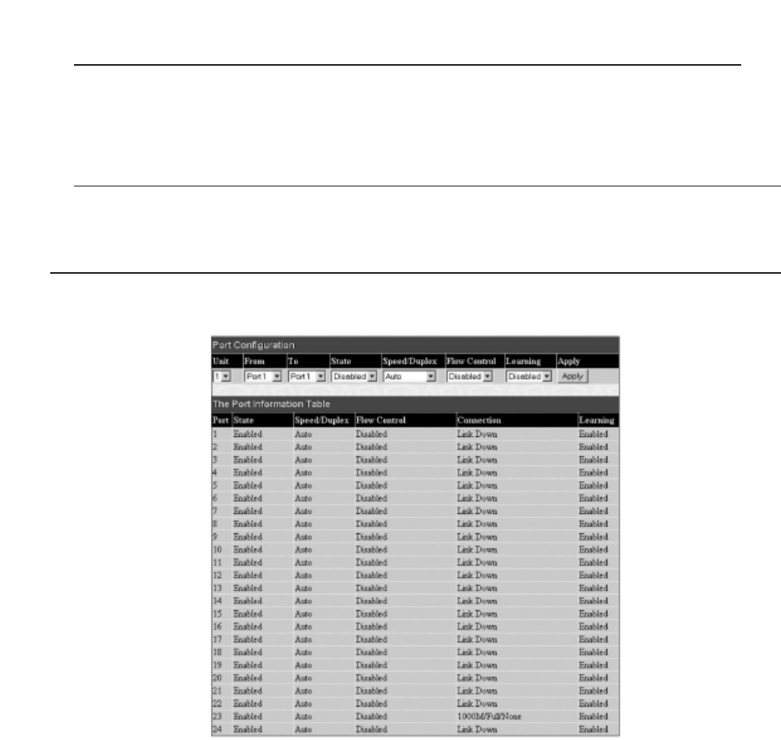
Parameter Description
Current Box ID The current Box ID of the Master switch in the stack.
New Box ID The new box ID of the Master switch in the stack.
Box Type The user may choose the model name of the Master switch in a stack to be the main configuring switch of that
stack.
Priority Displays the priority ID of the Switch.The lower the number, the higher the priority.The box (switch) with the
lowest priority number in the stack is the Master switch.
Information configured in this screen may be found in the Monitoring folder under Stack Information.
6-4 Port Configuration
This section contains information for configuring various attributes and properties for individual physical ports, including port speed and address learning. Clicking
on Port Configurations in the Configuration menu will display the following window for the user:
Figure 6- 5. Port Configuration and The Port Information Table window
To configure switch ports:
1. Choose the port or sequential range of ports using the From…To… port pull-down menus, and the Unit ID of the Switch to be configured.
2. Use the remaining pull-down menus to configure the parameters described below:
32
Allied Telesyn AT-9724TS High-Density Layer 3 Stackable Gigabit Ethernet Switch

Parameter Description
State Toggle the State <Enabled> field to either enable or disable a given port or group of ports.
Speed/Duplex Toggle the Speed/Duplex field to either select the speed and duplex/half-duplex state of the port. Auto
denotes auto-negotiation between 10 and 100Mbps devices, in full- or half-duplex.The Auto setting allows the
port to automatically determine the fastest settings the device the port is connected to can handle, and then to
use those settings.The other options are Auto,10M/Half,10M/Full,100M/Half and 100M/Full,1000M/Full_M and
1000M/Full_S.There is no automatic adjustment of port settings with any option other than Auto.
The Switch allows the user to configure two types of gigabit connections; 1000M/Full_M and 1000M/Full_S.
Gigabit connections are only supported in full duplex connections and take on certain characteristics that are
different from the other choices listed.
The 1000M/Full_M (master) and 1000M/Full_S (slave) parameters refer to connections running a 1000T cable
for connection between the Switch port and other device capable of a gigabit connection.The master setting
(1000M/Full_M) will allow the port to advertise capabilities related to duplex, speed and physical layer type.The
master setting will also determine the master and slave relationship between the two connected physical layers.
This relationship is necessary for establishing the timing control between the two physical layers.The timing
control is set on a master physical layer by a local source.The slave setting (1000M/Full_S) uses loop timing,
where the timing comes form a data stream received from the master. If one connection is set for
1000M/Full_M, the other side of the connection must be set for 1000M/Full_S.Any other configuration will
result in a link down status for both ports.
Flow Control Displays the flow control scheme used for the various port configurations. Ports configured for full-duplex use
802.3x flow control, half-duplex ports use backpressure flow control, and Auto ports use an automatic selection
of the two.The default is Disabled.
Learning Enable or disable MAC address learning for the selected ports.When Enabled, destination and source MAC
addresses are automatically listed in the forwarding table.When learning is Disabled, MAC addresses must be
manually entered into the forwarding table.This is sometimes done for reasons of security or efficiency. See the
section on Forwarding/Filtering for information on entering MAC addresses into the forwarding table.
The default setting is Disabled.
Click Apply to implement the new settings on the Switch.
6-5 Port Description
The AT-9724TS supports a port description feature where the user may name various ports on the Switch.To assign names to various ports, click the Port
Description on the Configuration menu:
Figure 6- 6. Port Description Setting and Port Description Table window
Use the From and To pull down menu to choose a port or range of ports to describe and Unit to choose the Switch in the switch stack, and then enter a
description of the port(s). Click Apply to set the descriptions in the Port Description Table.
33
Allied Telesyn AT-9724TS High-Density Layer 3 Stackable Gigabit Ethernet Switch

6-6 Port Mirroring
The Switch allows you to copy frames transmitted and received on a port and redirect the copies to another port.You can attach a monitoring device to the
mirrored port, such as a sniffer or an RMON probe, to view details about the packets passing through the first port.This is useful for network monitoring and
troubleshooting purposes.To view the Setup Port Mirroring window, click Port Mirroring in the Configuration folder.
Figure 6- 7. Setup Port Mirroring window
To configure a mirror port:
• Select the Source Port from where you want to copy frames and the Target Port, which receives the copies from the source port.
• Select the Source Direction,Ingress,Egress,or Both and change the Status drop-down menu to Enabled.
• Click Apply to let the changes take effect.
Note: You cannot mirror a fast port onto a slower port. For example, if you try to mirror the traffic from a 100Mbps port onto a 10Mbps port,
this can cause throughput problems.The port you are copying frames from should always support an equal or lower speed than the port to which
you are sending the copies.Also, the target port for the mirroring cannot be a member of a trunk group. Please note a target port and a source port
cannot be the same port.
6-7 Link Aggregation
Understanding Port Trunk Groups
Port trunk groups are used to combine a number of ports together to make a single high-bandwidth data pipeline.
The AT
-9724TS supports up to 32 port trunk groups with 2 to 8 ports in each group.A potential bit rate of 8000Mbps can be achieved.
Figure 6- 8. Example of Port Trunk Group
34
Allied Telesyn AT-9724TS High-Density Layer 3 Stackable Gigabit Ethernet Switch
PC PC PC PC PC PC PC PC PC
13 5 7911 13 15
24 6 8 10 12 14 16
17 19 21 23
18 20 22 24
21 22 23 24
2 4 6 8 10 12 14 16 18 20 22 24
1 3 5 7 9 11 13 15 17 19 21 23
Power
Master
Console
RPS
1000
Link
Act
1000
Link
Act
1
2
SIO Stack ID
AT- 9724TS
Port Trunk Group
13 5 7
2468
10/100/1000Mbps Backbone Switch
100Mbps 100Mbps 100Mbps
10/100Mbps Hub 10/100Mbps Hub10/100Mbps Hub
100Mbps
100Mbps100Mbps
100Mbps10Mbps10Mbps
10Mbps10Mbps

The Switch treats all ports in a trunk group as a single port. Data transmitted to a specific host (destination address) will always be transmitted over the same
port in a trunk group.This allows packets in a data stream to arrive in the same order they were sent.
Note: If any ports within the trunk group become disconnected, packets intended for the disconnected port will be load shared among the other
uplinked ports of the link aggregation group.
Link aggregation allows several ports to be grouped together and to act as a single link.This gives a bandwidth that is a multiple of a single link's bandwidth.
Link aggregation is most commonly used to link a bandwidth intensive network device or devices, such as a server, to the backbone of a network.
The Switch allows the creation of up to 32 link aggregation groups, each group consisting of 2 to 8 links (ports). All of the ports in the group must be members
of the same VLAN, and their STP status, static multicast, traffic control, traffic segmentation and 802.1p default priority configurations must be identical. Port
locking, port mirroring and 802.1X must not be enabled on the trunk group. Further, the aggregated links must all be of the same speed and should be configured
as full-duplex.
The Master Port of the group is to be configured by the user, and all configuration options, including the VLAN configuration that can be applied to the Master
Port, are applied to the entire link aggregation group.
Load balancing is automatically applied to the ports in the aggregated group, and a link failure within the group causes the network traffic to be directed to the
remaining links in the group.
The Spanning Tree Protocol will treat a link aggregation group as a single link, on the switch level. On the port level, the STP will use the port parameters of the
Master Port in the calculation of port cost and in determining the state of the link aggregation group. If two redundant link aggregation groups are configured on
the Switch, STP will block one entire group, in the same way STP will block a single port that has a redundant link.
To configure port trunking, click on the Link Aggregation hyperlink in the Configuration folder to bring up the Port Link Aggregation Group table:
Figure 6- 9. Current Link Aggregation Group Entries window
To configure port trunk groups, click the Add button to add a new trunk group and use the Link Aggregation Settings menu (see example below) to set
up trunk groups.To modify a port trunk group, click the hyperlinked group number corresponding to the entry you wish to alter.To delete a port trunk group,
click the corresponding 8under the Delete heading in the Current Link Aggregation Group Entries table.
Figure 6- 10. Link Aggregation Group Configuration window – Add
35
Allied Telesyn AT-9724TS High-Density Layer 3 Stackable Gigabit Ethernet Switch

Figure 6- 11. Link Aggregation Group Configuration window – Modify
The user-changeable parameters are as follows:
Parameter Description
Group ID Select an ID number for the group, between 1 and 32.
State Trunk groups can be toggled between Enabled and Disabled.This is used to turn a port trunking group on or off.
This is useful for diagnostics, to quickly isolate a bandwidth intensive network device or to have an absolute
backup aggregation group that is not under automatic control.
Master Port Choose the Master Port for the trunk group using the pull down menu.
Member Ports Choose the members of a trunked group. 2 to 8 ports can be assigned to an individual group.
Flooding PortA trunking group must designate one port to allow transmission of broadcasts and unknown unicasts.
Active Port Shows the port that is currently forwarding packets.
Type This pull-down menu allows you to select between Static and LACP (Link Aggregation Control Protocol). LACP
allows for the automatic detection of links in a Port Trunking Group.
After setting the previous parameters, click Apply to allow your changes to be implemented. Successfully created trunk groups will be show in the Current
Link Aggregation Group Entries.
6-8 LACP Port Setting
The LACP Port Setting window is used in conjunction with the Link Aggregation window to create port trunking groups on the Switch. Using the
following window, the user may set which ports will be active and passive in processing and sending LACP control frames.
Figure 6- 12. LACP Port Setting and LACP Port Information window
36
Allied Telesyn AT-9724TS High-Density Layer 3 Stackable Gigabit Ethernet Switch

The user may set the following parameters:
Parameter Description
Unit Choose the switch in the switch stack to be configured by using the pull-down menu.
From/To A consecutive group of ports may be configured starting with the selected port.
Mode Active – Active LACP ports are capable of processing and sending LACP control frames.This allows LACP
compliant devices to negotiate the aggregated link so the group may be changed dynamically as needs require.
In order to utilize the ability to change an aggregated port group, that is, to add or subtract ports from the
group, at least one of the participating devices must designate LACP ports as active. Both devices must support
LACP.
Passive – LACP ports that are designated as passive cannot initially send LACP control frames. In order to allow
the linked port group to negotiate adjustments and make changes dynamically, one end of the connection must
have "active" LACP ports (see above).
After setting the previous parameters, click Apply to allow your changes to be implemented.The LACP Port Table shows which ports are active and/or
passive.
6-9 MAC Notification
MAC Notification is used to monitor MAC addresses learned and entered into the forwarding database.
MAC Notification Global Settings
To globally set MAC notification on the Switch, open the following screen by opening the MAC Notification folder and clicking the MAC Notification
Global Settings link:
Figure 6- 13. Current and New MAC Notification Global Settings window
The following parameters may be modified:
Parameter Description
State Enable or disable MAC notification globally on the Switch.The default setting is Disabled.
Interval (sec) The user may set the time, between 1 and 2,147,483,647 seconds, between MAC notifications.The default
setting is 1 second.
History size The maximum number of entries listed in the history log used for notification. Up to 500 entries can be
specified.The default setting is 1.
Current MAC notification configurations can be viewed in the Current MACNotification Global Settings window,as seen above.
37
Allied Telesyn AT-9724TS High-Density Layer 3 Stackable Gigabit Ethernet Switch

MAC Notification Port Settings
To change MAC notification settings for a port or group of ports on the Switch, click Port Settings in the MAC Notification folder, which will display the
following screen:
Figure 6- 14. MAC Notification Port Settings and Port State Table
The following parameters may be set:
Parameter Description
Unit Choose the Switch ID number of the Switch in the switch stack to be modified.
From…ToSelect a port or group of ports to enable for MAC notification using the pull down menus.
State Enable MAC Notification for the ports selected using the pull down menu.
Click Apply to implement changes made.
6-10 IGMP
Computers and network devices that want to receive multicast transmissions need to inform nearby routers that they will become members of a multicast
group.The Internet Group Management Protocol (IGMP) is used to communicate this information. IGMP is also used to periodically check the
multicast group for members that are no longer active.
In the case where there is more than one multicast router on a subnetwork, one router is elected as the ‘querier’.This router then keeps track of the
membership of the multicast groups that have active members.The information received from IGMP is then used to determine if multicast packets should be
forwarded to a given subnetwork or not.The router can check, using IGMP, to see if there is at least one member of a multicast group on a given subnetwork. If
there are no members on a subnetwork, packets will not be forwarded to that subnetwork.
IGMP Versions 1 and 2
Multicast groups allow members to join or leave at any time. IGMP provides the method for members and multicast routers to communicate when joining or
leaving a multicast group.
IGMP version 1 is defined in RFC 1112. It has a fixed packet size and no optional data.
38
Allied Telesyn AT-9724TS High-Density Layer 3 Stackable Gigabit Ethernet Switch

The format of an IGMP packet is shown below:
Figure 6- 15. IGMP Message Format
The IGMP Type codes are shown below:
Type Meaning
0x11 Membership Query (if Group Address is 0.0.0.0)
0x11 Specific Group Membership Query (if Group Address is Present)
0x16 Membership Report (version 2)
0x17 Leave a Group (version 2)
0x12 Membership Report (version 1)
Table 6- 1. IGMP Type Codes
IGMP packets enable multicast routers to keep track of the membership of multicast groups, on their respective subnetworks.The following outlines what is
communicated between a multicast router and a multicast group member using IGMP.
A host sends an IGMP “report” to join a group.
A host will never send a report when it wants to leave a group (for version 1).
A host will send a “leave” report when it wants to leave a group (for version 2).
Multicast routers send IGMP queries (to the all-hosts group address: 224.0.0.1) periodically to see whether any group members exist on their subnetworks. If
there is no response from a particular group, the router assumes that there are no group members on the network.
The Time-to-Live (TTL) field of query messages is set to 1 so that the queries will not be forwarded to other subnetworks.
IGMP version 2 introduces some enhancements such as a method to elect a multicast querier for each LAN, an explicit leave message, and query messages that
are specific to a given group.
The states a computer will go through to join or to leave a multicast group are shown below:
Figure 6- 16. IGMP State Transitions
39
Allied Telesyn AT-9724TS High-Density Layer 3 Stackable Gigabit Ethernet Switch
Non-
Member
Delaying
Member
Member
IGMP State
Tr a nsitions
Join Group
Start Timer
Leave Group
Stop Timer
Timer Expires
Send Response
Query Received
Start Timer
Another Host
Responds
Stop Timer
Count
Becomes
Zero
Leave
Group
Octets
IGMP Message Format
Group Address (all zeros if this is a query)
08 16 31
Ty p eResponse Time Checksum
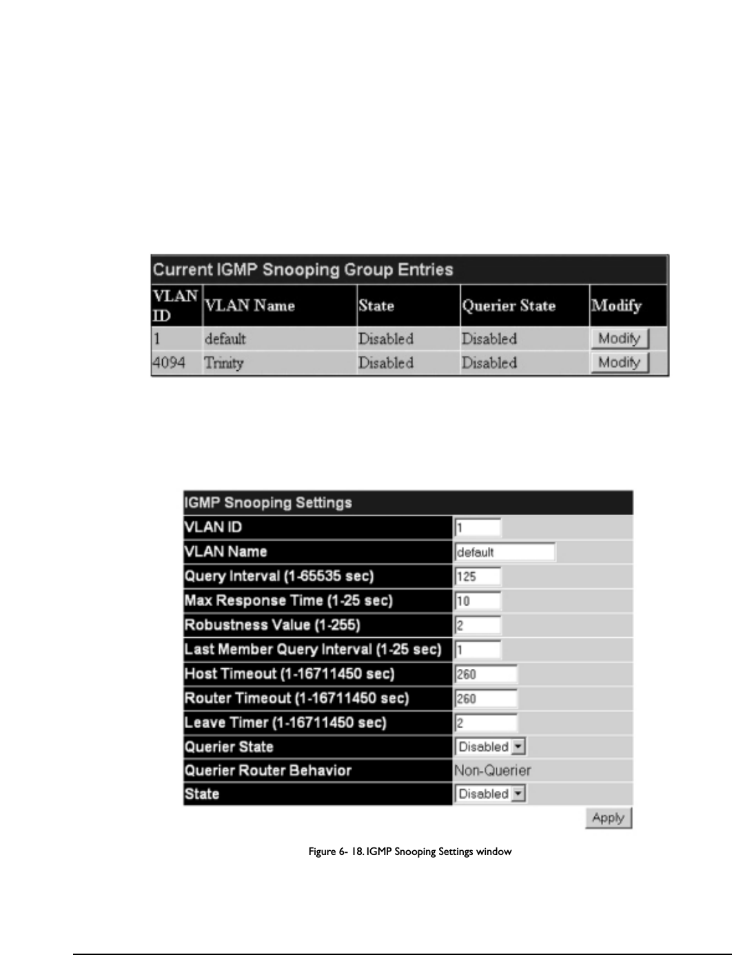
IGMP Snooping
Internet Group Management Protocol (IGMP) snooping allows the Switch to recognize IGMP queries and reports sent between network stations or
devices and an IGMP host.When enabled for IGMP snooping, the Switch can open or close a port to a specific device based on IGMP messages passing through
the Switch.
In order to use IGMP Snooping it must first be enabled for the entire Switch (see Advanced Settings).You may then fine-tune the settings for each VLAN
using the IGMP Snooping link in the Configuration folder. When enabled for IGMP snooping, the Switch can open or close a port to a specific Multicast
group member based on IGMP messages sent from the device to the IGMP host or vice versa.The Switch monitors IGMP messages and discontinues forwarding
multicast packets when there are no longer hosts requesting that they continue. Use the IGMP Snooping Group Entry Table to view IGMP Snooping
status.To modify settings, click the Modify button for the VLAN Name entry you want to change.
Use the Current IGMP Snooping Group Entries window to view IGMP Snooping settings.To modify settings, click the Modify button for the VLAN
ID you want to change.
Figure 6- 17. Current IGMP Snooping Group Entries
Clicking the Modify button will open the IGMP Snooping Settings menu, shown below:
Figure 6- 18. IGMP Snooping Settings window
The following parameters may be viewed or modified:
Parameter Description
VLAN ID This is the VLAN ID that, along with the VLAN Name, identifies the VLAN the user wishes to modify the
IGMP Snooping Settings for.
VLAN Name This is the VLAN Name that, along with the VLAN ID, identifies the VLAN the user wishes to modify the
IGMP Snooping Settings for.
Query Interval The Query Interval field is used to set the time (in seconds) between transmitting IGMP queries. Entries
between 1 and 65535 seconds are allowed. Default = 125.
Max Response Time This determines the maximum amount of time in seconds allowed before sending an IGMP response report.
The Max Response Time field allows an entry between 1 and 25 (seconds). Default = 10.
40
Allied Telesyn AT-9724TS High-Density Layer 3 Stackable Gigabit Ethernet Switch
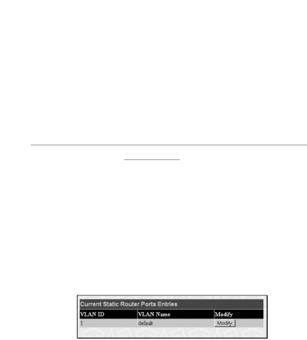
Robustness Value Adjust this variable according to expected packet loss. If packet loss on the VLAN is expected to be high, the
Robustness Variable should be increased to accommodate increased packet loss.This entry field allows an
entry of 1 to 255. Default = 2.
Last Member Query Interval This field specifies the maximum amount of time between group-specific query messages, including those sent
in response to leave group messages. Default = 1.
Host Timeout This is the maximum amount of time in seconds allowed for a host to continue membership in a multicast
group without the Switch receiving a host membership report. Default = 260.
Router Timeout This is the maximum amount of time in seconds a route is kept in the forwarding table without receiving a
membership report. Default = 260.
Leave Timer This specifies the maximum amount of time in seconds between the Switch receiving a leave group message
from a host, and the Switch issuing a group membership query. If no response to the membership query is
received before the Leave Timer expires, the (multicast) forwarding entry for that host is deleted.
Querier State Choose Enabled to enable transmitting IGMP Query packets or Disabled to disable.The default is Disabled.
Querier Router Behavior This read-only field describes the behavior of the router for sending query packets. Querier will denote that the
router is sending out IGMP query packets. Non-Querier will denote that the router is not sending out IGMP
query packets.This field will only read Querier when the Querier State and the State fields have been
Enabled.
State Select Enabled to implement IGMP Snooping.This field is Disabled by default.
Click Apply to implement the new settings. Click the Show All IGMP Group Entries link to return to the Current IGMP Snooping Group Entries
window.
Static Router Ports
A static router port is a port that has a multicast router attached to it. Generally, this router would have a connection to a WAN or to the Internet. Establishing a
router port will allow multicast packets coming from the router to be propagated through the network, as well as allowing multicast messages (IGMP) coming
from the network to be propagated to the router.
A router port has the following behavior:
• All IGMP Report packets will be forwarded to the router port.
• IGMP queries (from the router port) will be flooded to all ports.
• All UDP multicast packets will be forwarded to the router port. Because routers do not send IGMP reports or implement IGMP snooping, a multicast
router connected to the router port of a Layer 3 switch would not be able to receive UDP data streams unless the UDP multicast packets were all
forwarded to the router port.
A router port will be dynamically configured when IGMP query packets, RIPv2 multicast, DVMRP multicast or PIM-DM multicast packets are detected flowing
into a port.
Open the IGMP folder and the click on the Static Router Ports Entry link to open the Current Static Router Ports Entries page, as shown
below.
Figure 6- 19. Current Static Router Ports Entries window
The Current Static Router Ports Entries page (shown above) displays all of the current entries to the Switch's static router port table.To modify an
entry, click the Modify button.This will open the Static Router Ports Settings page, as shown below.
41
Allied Telesyn AT-9724TS High-Density Layer 3 Stackable Gigabit Ethernet Switch

Figure 6- 20. Static Router Ports Settings window
The following parameters can be set:
Parameter Description
VID (VLAN ID) This is the VLAN ID that, along with the VLAN Name, identifies the VLAN where the multicast router is
attached.
VLAN Name This is the name of the VLAN where the multicast router is attached.
Unit Choose the Switch ID number of the Switch in the switch stack to be modified.
Member Ports These are the ports on the Switch that will have a multicast router attached to them.
Click Apply to implement the new settings, click the Show All Static Router Port Entries link to return to the Current Static Router Port Entries
window.
6.11 Spanning Tree
This Switch supports three versions of the Spanning Tree Protocol; 802.1d STP, 802.1w Rapid STP and 802.1s MSTP. 802.1d STP will be familiar to most
networking professionals. However, since 802.1w RSTP and 802.1s MSTP has been recently introduced to Allied Telesyn managed Ethernet switches, a brief
introduction to the technology is provided below followed by a description of how to set up 802.1d STP, 802.1w RSTP and 802.1s MSTP.
802.1s MSTP
Multiple Spanning Tree Protocol, or MSTP, is a standard defined by the IEEE community that allows multiple VLANs to be mapped to a single spanning tree
instance,which will provide multiple pathways across the network.Therefore, these MSTP configurations will balance the traffic load, preventing wide scale
disruptions when a single spanning tree instance fails.This will allow for faster convergences of new topologies for the failed instance. Frames designated for these
VLANs will be processed quickly and completely throughout interconnected bridges utilizing either of the three spanning tree protocols (STP, RSTP or MSTP).
This protocol will also tag BDPU packets so receiving devices can distinguish spanning tree instances, spanning tree regions and the VLANs associated with them.
These instances will be classified by an MSTI ID. MSTP will connect multiple spanning trees with a Common and Internal Spanning Tree (CIST).The CIST will
automatically determine each MSTP region, its maximum possible extent and will appear as one virtual bridge that runs a single spanning tree. Consequentially,
frames assigned to different VLANs will follow different data routes within administratively established regions on the network, continuing to allow simple and full
processing of frames, regardless of administrative errors in defining VLANs and their respective spanning trees.
Each switch utilizing the MSTP on a network will have a single MSTP configuration that will have the following three attributes:
1. A configuration name defined by an alphanumeric string of up to 32 characters (defined in the MST Configuration Table window in the
Configuration Name field).
2. A configuration revision number (named here as a Revision Level and found in the MST Configuration Table window) and;
3. A 4096 element table (defined here as a VID List in the MST Configuration Table window) which will associate each of the possible 4096
VLANs supported by the Switch for a given instance.
T
o utilize the MSTP function on the Switch, three steps need to be taken:
1. The Switch must be set to the MSTP setting (found in the STP Bridge Global Settings window in the STP Version field).
2. The correct spanning tree priority for the MSTP instance must be entered (defined here as a Priority in the STP Instance Settings window
when configuring an MSTI ID settings).
3. VLANs that will be shared must be added to the MSTP Instance ID (defined here as a VID List in the MST Configuration Table window
when configuring an MSTI ID settings).
42
Allied Telesyn AT-9724TS High-Density Layer 3 Stackable Gigabit Ethernet Switch

802.1w Rapid Spanning Tree
The Switch implements three versions of the Spanning Tree Protocol, the Multiple Spanning Tree Protocol (MSTP) as defined by the IEEE 802.1s, the Rapid
Spanning Tree Protocol (RSTP) as defined by the IEEE 802.1w specification and a version compatible with the IEEE 802.1d STP. RSTP can operate with legacy
equipment implementing IEEE 802.1d, however the advantages of using RSTP will be lost.
The IEEE 802.1w Rapid Spanning Tree Protocol (RSTP) evolved from the 802.1d STP standard. RSTP was developed in order to overcome some limitations of
STP that impede the function of some recent switching innovations, in particular, certain Layer 3 functions that are increasingly handled by Ethernet switches.The
basic function and much of the terminology is the same as STP. Most of the settings configured for STP are also used for RSTP. This section introduces some new
Spanning Tree concepts and illustrates the main differences between the two protocols.
Port Transition States
An essential difference between the three protocols is in the way ports transition to a forwarding state and in the way this transition relates to the role of the
port (forwarding or not forwarding) in the topology. MSTP and RSTP combine the transition states disabled, blocking and listening used in 802.1d and creates a
single state Discarding. In either case, ports do not forward packets. In the STP port transition states disabled, blocking or listening or in the RSTP/MSTP port
state discarding, there is no functional difference, the port is not active in the network topology.Table 6-1 below compares how the three protocols differ
regarding the port state transition.
All three protocols calculate a stable topology in the same way. Every segment will have a single path to the root bridge.All bridges listen for BPDU packets.
However, BPDU packets are sent more frequently – with every Hello packet. BPDU packets are sent even if a BPDU packet was not received.Therefore, each link
between bridges is sensitive to the status of the link. Ultimately this difference results in faster detection of failed links, and thus faster topology adjustment.A
draw-back of 802.1d is this absence of immediate feedback from adjacent bridges.
802.1d MSTP 802.1w RSTP 802.1d STP Forwarding Learning
Discarding Discarding Disabled No No
Discarding Discarding Blocking No No
Discarding Discarding Listening No No
Learning Learning Learning No Yes
Forwarding Forwarding Forwarding Yes Yes
Table 6- 2. Comparing Port States
RSTP is capable of a more rapid transition to a forwarding state – it no longer relies on timer configurations – RSTP compliant bridges are sensitive to feedback
from other RSTP compliant bridge links. Ports do not need to wait for the topology to stabilize before transitioning to a forwarding state. In order to allow this
rapid transition, the protocol introduces two new variables: the edge port and the point-to-point (P2P) port.
Edge Port
The edge port is a configurable designation used for a port that is directly connected to a segment where a loop cannot be created. An example would be a port
connected directly to a single workstation. Ports that are designated as edge ports transition to a forwarding state immediately without going through the
listening and learning states. An edge port loses its status if it receives a BPDU packet, immediately becoming a normal spanning tree port.
P2P Port
A P2P port is also capable of rapid transition. P2P ports may be used to connect to other bridges. Under RSTP/MSTP, all ports operating in full-duplex mode are
considered to be P2P ports, unless manually overridden through configuration.
802.1d / 802.1w / 802.1s Compatibility
MSTP or RSTP can interoperate with legacy equipment and is capable of automatically adjusting BPDU packets to 802.1d format when necessary. However, any
segment using 802.1d STP will not benefit from the rapid transition and rapid topology change detection of MSTP or RSTP
.The protocol also provides for a
variable used for migration in the event that legacy equipment on a segment is updated to use RSTP or MSTP.
The Spanning Tree Protocol (STP) operates on two levels:
1. On the switch level, the settings are globally implemented.
2. On the port level, the settings are implemented on a per user-defined group of ports basis.
STP Bridge Global Settings
To open the following window, open the Spanning Tree folder in the Configuration menu and click the STP Bridge Global Settings link.
43
Allied Telesyn AT-9724TS High-Density Layer 3 Stackable Gigabit Ethernet Switch
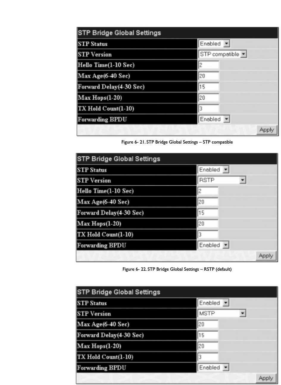
Figure 6- 21. STP Bridge Global Settings – STP compatible
Figure 6- 22. STP Bridge Global Settings – RSTP (default)
Figure 6- 23. STP Bridge Global Settings
The following parameters can be set:
44
Allied Telesyn AT-9724TS High-Density Layer 3 Stackable Gigabit Ethernet Switch

Parameter Description
STP Status Use the pull-down menu to enable or disable STP globally on the Switch.The default is Disabled.
STP Version Use the pull-down menu to choose the desired version of STP to be implemented on the Switch.There are
three choices:
STP – Select this parameter to set the Spanning Tree Protocol (STP) globally on the switch.
RSTP – Select this parameter to set the Rapid Spanning Tree Protocol (RSTP) globally on the Switch.
MSTP – Select this parameter to set the Multiple Spanning Tree Protocol (MSTP) globally on the Switch.
Hello Time: (1-10 sec)The Hello Time can be set from 1 to 10 seconds.This is the interval between two transmissions of BPDU
packets sent by the Root Bridge to tell all other switches that it is indeed the Root Bridge.This field will only
appear here when STP or RSTP is selected for the STP Version. For MSTP, the Hello Time must be set on a port
per port basis. See the MST Port Settings section for further details.
Max Age: (6 - 40 sec)The Max Age may be set to ensure that old information does not endlessly circulate through redundant
paths in the network, preventing the effective propagation of the new information. Set by the Root Bridge, this
value will aid in determining that the Switch has spanning tree configuration values consistent with other
devices on the bridged LAN. If the value ages out and a BPDU has still not been received from the Root Bridge,
the Switch will start sending its own BPDU to all other switches for permission to become the Root Bridge. If
it turns out that your switch has the lowest Bridge Identifier, it will become the Root Bridge.The user may
choose a time between 6 and 40 seconds.The default value is 20.
Forward Delay: (4 – 30 sec)The Forward Delay can be from 4 to 30 seconds.Any port on the Switch spends this time in the listening
state while moving from the blocking state to the forwarding state.
Max Hops (1-20) Used to set the number of hops between devices in a spanning tree region before the BPDU (bridge protocol
data unit) packet sent by the Switch will be discarded. Each switch on the hop count will reduce the hop count
by one until the value reaches zero.The Switch will then discard the BDPU packet and the information held for
the port will age out.The user may set a hop count from 1 to 20.The default is 20.
TX Hold Count (1-10) Used to set the maximum number of Hello packets transmitted per interval.The count can be specified from 1
to 10.The default is 3.
Forwarding BPDU This field can be Enabled or Disabled.When Enabled, it allows the forwarding of STP BPDU packets from other
network devices.The default is Enabled.
Click Apply to implement changes made.
Note: The Hello Time cannot be longer than the Max.Age. Otherwise, a configuration error will occur. Observe the following formulas when
setting the above parameters:
Max.Age ≤ 2 x (Forward Delay - 1 second)
Max.Age ≤ 2 x (Hello Time + 1 second)
MST Configuration Table
The following screens in the MST Configuration Table window allow the user to configure a MSTI instance on the Switch.These settings will uniquely
identify a multiple spanning tree instance set on the Switch.The Switch initially possesses one CIST or Common Internal Spanning Tree of which the user may
modify the parameters for but cannot change the MSTI ID for, and cannot be deleted.To view the Current MST Configuration Identification window,
click Configuration > Spanning Tree > MST Configuration Table:
Figure 6- 24. Current MST Configuration Identification window
45
Allied Telesyn AT-9724TS High-Density Layer 3 Stackable Gigabit Ethernet Switch

The window above contains the following information:
Parameter Description
Configuration Name A previously configured name set on the Switch to uniquely identify the MSTI (Multiple Spanning Tree Instance).
If a configuration name is not set, this field will show the MAC address to the device running MSTP.
Revision Level This value, along with the Configuration Name will identify the MSTP region configured on the Switch.
MSTI ID This field shows the MSTI IDs currently set on the Switch.This field will always have the CIST MSTI, which
may be configured but not deleted. Clicking the hyperlinked name will open a new window for configuring
parameters associated with that particular MSTI.
VID List This field displays the VLAN IDs associated with the specific MSTI.
To delete a previously set MSTI Instance ID, click the corresponding 8 under the Delete heading in the Current MST Configuration Identification
window. Clicking the Add button will reveal the following window to configure:
Figure 6- 25. Instance ID Settings window – Add
The user may configure the following parameters to create a MSTI in the Switch.
Parameter Description
MSTI ID Enter a number between 1 and 15 to set a new MSTI on the Switch.
Type Create is selected to create a new MSTI. No other choices are available for this field when creating a new
MSTI.
VID List (1-4094) This field is used to specify the
VID range from configured VLANs set on the Switch. Supported VIDs on the
Switch range from ID number 1 to 4094.
Click Apply to implement changes made.
To configure the settings for the CIST, click on its hyperlinked MSTI ID number in the Current MST Configuration Identification window, which will
reveal the following window to configure:
Figure 6- 26. Instance ID Settings window – CIST modify
46
Allied Telesyn AT-9724TS High-Density Layer 3 Stackable Gigabit Ethernet Switch

The user may configure the following parameters to configure the CIST on the Switch.
Parameter Description
MSTI ID The MSTI ID of the CIST is 0 and cannot be altered.
Type The type of configuration about to be processed.This window is used to add or delete VIDs to the configured
MSTI or internal CIST. All other parameters are permanently set and therefore unchangeable.
VID List (1-4094) This field is used to specify the VID range from configured VLANs set on the Switch. Supported VIDs on the
Switch range from ID number 1 to 4094.
Click Apply to implement changes made.
To configure the parameters for a previously set MSTI, click on its hyperlinked MSTI ID number, which will reveal the following screen for configuration.
Figure 6- 27. Instance ID Settings window – modify
The user may configure the following parameters for a MSTI on the Switch.
Parameter Description
MSTI ID Displays the MSTI ID previously set by the user.
Type This field allows the user to choose a desired method for altering the MSTI settings.The user has 4 choices.
Add VID – Select this parameter to add VIDs to the MSTI ID, in conjunction with the VID List parameter.
Remove VID – Select this parameter to remove VIDs from the MSTI ID, in conjunction with the VID List
parameter.
VID List (1-4094) This field is used to specify the
VID range from configured VLANs set on the Switch that the user wishes to add
to this MSTI ID. Supported VIDs on the Switch range from ID number 1 to 4094.This parameter can only be
utilized if the Type chosen is Add or Remove.
Click Apply to implement changes made.
47
Allied Telesyn AT-9724TS High-Density Layer 3 Stackable Gigabit Ethernet Switch

MSTI Port Information
This window displays the current MSTI configuration settings and can be used to update the port configuration for an MSTI ID. If a loop occurs, the MSTP
function will use the port priority to select an interface to put into the forwarding state. Set a higher priority value for interfaces to be selected for forwarding
first. In instances where the priority value is identical, the MSTP function will implement the lowest port number into the forwarding state and other interfaces
will be blocked. Remember that lower priority values mean higher priorities for forwarding packets.
To view the following window, click Configuration > Spanning Tree > MST Port Information:
Figure 6- 28. MSTP Port Information window
To view the MSTI settings for a particular port, select the Port number and the Unit ID number of the switch in the switch stack, located in the top left hand
corner of the screen and click Apply. To modify the settings for a particular MSTI Instance, click on its hyperlinked MSTI ID, which will reveal the following
window.
Figure 6- 29. MSTI Settings window
Parameter Description
Instance ID Displays the MSTI ID of the instance being configured.An entry of 0 in this field denotes the CIST (default
MSTI).
Internal cost (0=Auto) This parameter is set to represent the relative cost of forwarding packets to specified ports when an interface
is selected within a STP instance.The default setting is 0 (auto).There are two options:
0 (auto) – Selecting this parameter for the internal Cost will set quickest route automatically and optimally for
an interface.The default value is derived from the media speed of the interface.
value 1-2000000 – Selecting this parameter with a value in the range of 1-2000000 will set the quickest route
when a loop occurs. A lower Internal cost represents a quicker transmission.
Priority Enter a value between 0 and 240 to set the priority for the port interface. A higher priority will designate the
interface to forward packets first. A lower number denotes a higher priority.This entry must be divisible by 16.
The default priority setting is 128.
Click Apply to implement changes made.
48
Allied Telesyn AT-9724TS High-Density Layer 3 Stackable Gigabit Ethernet Switch

49
Allied Telesyn AT-9724TS High-Density Layer 3 Stackable Gigabit Ethernet Switch
STP Instance Settings
The following window displays MSTIs currently set on the Switch.To view the following table, click Configuration > Spanning Tree > STP Instance
Settings:
Figure 6- 30. STP Instance Settings
The following information is displayed:
Parameter Description
Instance Type Displays the instance type(s) currently configured on the Switch. Each instance type is classified by a MSTI ID.
CIST refers to the default MSTI configuration set on the Switch.
Instance Status Displays the current status of the corresponding MSTI ID.
Instance Priority Displays the priority of the corresponding MSTI ID.The lowest priority will be the root bridge.
Priority Click the Modify button to change the priority of the MSTI.This will open the Instance ID Settings window to
configure.The Type field in this window will be permanently set to Set Priority Only. Enter the new priority in
the Priority field and click Apply to implement the new priority setting.
Click Apply to implement changes made.
Clicking the hyperlinked name will allow the user to view the current parameters set for the MSTI Instance.
Figure 6- 31. STP Instance Operational Status – CIST

Figure 6- 32. STP Instance Operational Status – Previously Configured MSTI
The following parameters may be viewed in the STP Instance Operational Status windows:
Parameter Description
Designated Root Bridge This field will show the priority and MAC address of the Root Bridge.
External Root Cost This defines a metric that indicates the relative cost of forwarding packets to the specified port list. Port cost
can be set automatically or as a metric value.The default value is 0 (auto).
0 (auto) – Setting 0 for the external cost will automatically set the speed for forwarding packets to the specified
port(s) in the list for optimal efficiency. Default port cost: 100Mbps port = 200000. Gigabit port = 20000.
value 1-200000000 – Define a value between 1 and 200000000 to determine the external cost.The lower the
number, the greater the probability the port will be chosen to forward packets.
Regional Root Bridge This field will show the priority and MAC address of the Regional (Internal) Root Bridge.This MAC address
should be the MAC address of the Switch.
Internal Root Cost This parameter is set to represent the relative cost of forwarding packets to specified ports when an interface
is selected within a STP instance.The default setting is 0 (auto).There are two options:
0 (auto) – Selecting this parameter for the internalCost will set quickest route automatically and optimally for an
interface.The default value is derived from the media speed of the interface.
value 1-2000000 – Selecting this parameter with a value in the range of 1-2000000 will set the quickest route
when a loop occurs.A lower Internal cost represents a quicker transmission.
Designated Bridge This field will show the priority and MAC address of the Designated Bridge.The information shown in this table
comes from a BPDU packet originating from this bridge.
Root Port This is the port on the Switch that is physically connected to the Root Bridge.
Max Age The Max Age may be set to ensure that old information does not endlessly circulate through redundant
paths in the network, preventing the effective propagation of the new information. Set by the Root Bridge, this
value will aid in determining that the Switch has spanning tree configuration values consistent with other
devices on the bridged LAN. If the value ages out and a BPDU has still not been received from the Root Bridge,
the Switch will start sending its own BPDU to all other switches for permission to become the Root Bridge. If
it turns out that your switch has the lowest Bridge Identifier, it will become the Root Bridge.The user may
choose a time between 6 and 40 seconds.The default value is 20.
Forward Delay The Forward Delay can be from 4 to 30 seconds.Any port on the Switch spends this time in the listening
state while moving from the blocking state to the forwarding state.
Last Topology Change This field shows the time, in seconds, since the last spanning tree topology change.
Topology Changes Count This field displays the number of times that the spanning tree topology has changed since the original initial
boot up of the Switch.
50
Allied Telesyn AT-9724TS High-Density Layer 3 Stackable Gigabit Ethernet Switch

STP Port Settings
STP can be set up on a port per port basis.To view the following window click Configuration > Spanning Tree > STP Port Settings:
Figure 6- 33. STP Port Settings and MSTP Port Information Table
In addition to setting Spanning Tree parameters for use on the switch level, the Switch allows for the configuration of groups of ports, each port-group of which
will have its own spanning tree, and will require some of its own configuration settings. An STP Group will use the switch-level parameters entered above, with
the addition of Port Priority and Port Cost.
An STP Group spanning tree works in the same way as the switch-level spanning tree, but the root bridge concept is replaced with a root port concept. A root
port is a port of the group that is elected based on port priority and port cost, to be the connection to the network for the group. Redundant links will be
blocked, just as redundant links are blocked on the switch level.
The STP on the switch level blocks redundant links between switches (and similar network devices).The port level STP will block redundant links within an STP
Group.
It is advisable to define an STP Group to correspond to a VLAN group of ports.
The following fields can be set:
Parameter Description
Unit Choose the Switch ID number of the Switch in the switch stack to be modified.
From/To A consecutive group of ports may be configured starting with the selected port.
External Cost This defines a metric that indicates the relative cost of forwarding packets to the specified port list. Port cost
can be set automatically or as a metric value.The default value is 0 (auto).
51
Allied Telesyn AT-9724TS High-Density Layer 3 Stackable Gigabit Ethernet Switch

0 (auto) – Setting 0 for the external cost will automatically set the speed for forwarding packets to the specified
port(s) in the list for optimal efficiency. Default port cost: 100Mbps port = 200000. Gigabit port = 20000.
value 1-200000000 – Define a value between 1 and 200000000 to determine the external cost.The lower the
number, the greater the probability the port will be chosen to forward packets.
Hello Time The time interval between the transmission of configuration messages by the designated port, to other devices
on the bridged LAN, thus stating that the Switch is still functioning.The user may choose a time between 1 and
10 seconds.The default is 2 seconds.This field is only operable when the Switch is enabled for MSTP.
Migration Setting this parameter as "yes" will set the ports to send out BDPU packets to other bridges, requesting
information on their STP setting If the Switch is configured for RSTP, the port will be capable to migrate from
802.1d STP to 802.1w RSTP. If the Switch is configured for MSTP, the port is capable of migrating from 802.1d
STP to 802.1s MSTP. RSTP and MSTP can coexist with standard STP, however the benefits of RSTP and MSTP
are not realized on a port where an 802.1d network connects to an 802.1w or 802.1s enabled network.
Migration should be set as yes on ports connected to network stations or segments that are capable of being
upgraded to 802.1w RSTP or 802.1s MSTP on all or some portion of the segment.
Edge Choosing the true parameter designates the port as an edge port. Edge ports cannot create loops, however an
edge port can lose edge port status if a topology change creates a potential for a loop. An edge port normally
should not receive BPDU packets. If a BPDU packet is received, it automatically loses edge port status.
Choosing the false parameter indicates that the port does not have edge port status.
P2P Choosing the True parameter indicates a point-to-point (P2P) shared link. P2P ports are similar to edge ports,
however they are restricted in that a P2P port must operate in full-duplex. Like edge ports, P2P ports transition
to a forwarding state rapidly thus benefiting from RSTP. A p2p value of false indicates that the port cannot have
p2p status.Auto allows the port to have p2p status whenever possible and operate as if the p2p status were
true. If the port cannot maintain this status, (for example if the port is forced to half-duplex operation) the p2p
status changes to operate as if the p2p value were False.The default setting for this parameter is True.
State This drop-down menu allows you to enable or disable STP for the selected group of ports.The default is
Enabled.
Click Apply to implement changes made.
6-13 Forwarding & Filtering
Unicast Forwarding
Open the Forwarding & Filtering folder in the Configuration menu and click on the Unicast Forwarding link.This will open the Setup Static
Unicast Forwarding Table,as shown below:
Figure 6- 34. Setup Static Unicast Forwarding Table and Static Unicast Forwarding Table window
To add or edit an entry, define the following parameters and then click Add/Modify:
Parameter Description
VLAN ID (VID) The VLAN ID number of the VLAN on which the above Unicast MAC address resides.
MAC Address The MAC address to which packets will be statically forwarded.This must be a unicast MAC address.
Unit Choose the Switch ID number of the Switch in the switch stack to be modified.
Port Allows the selection of the port number on which the MAC address entered above resides.
Click Apply to implement the changes made.To delete an entry in the Static Unicast Forwarding Table, click the corresponding 8 under the Delete
heading.
52
Allied Telesyn AT-9724TS High-Density Layer 3 Stackable Gigabit Ethernet Switch

Static Multicast Forwarding
The following figure and table describe how to set up Multicast Forwarding on the Switch. Open the Forwarding Filtering folder and click on the
Multicast Forwarding link to see the entry screen below:
Figure 6- 35. Static Multicast Forwarding Settings and Current Multicast Forwarding Entries
The Static Multicast Forwarding Settings page displays all of the entries made into the Switch's static multicast forwarding table. Click the Add button
to open the Setup Static Multicast Forwarding Table, as shown below:
Figure 6- 36. Setup Static Multicast Forwarding Table
The following parameters can be set:
Parameter Description
Unit Choose the Switch ID number of the Switch in the switch stack to be modified.
VID The VLAN ID of the VLAN the corresponding MAC address belongs to.
Multicast MAC Address The MAC address of the static source of multicast packets.This must be a multicast MAC address.
Port Allows the selection of ports that will be members of the static multicast group.The options are:
None – No restrictions on the port dynamically joining the multicast group.When None is chosen, the port will
not be a member of the Static Multicast Group.
Egress – The port is a static member of the multicast group.
Click Apply to implement the changes made.To delete an entry in the Static Multicast Forwarding Table, click the corresponding 8 under the Delete
heading. Click the Show All Multicast Forwarding Entries link to return to the Static Multicast Forwarding Settings window.
53
Allied Telesyn AT-9724TS High-Density Layer 3 Stackable Gigabit Ethernet Switch

6-14 VLANs
Understanding IEEE 802.1p Priority
Priority tagging is a function defined by the IEEE 802.1p standard designed to provide a means of managing traffic on a network where many different types of
data may be transmitted simultaneously. It is intended to alleviate problems associated with the delivery of time critical data over congested networks.The quality
of applications that are dependent on such time critical data, such as video conferencing, can be severely and adversely affected by even very small delays in
transmission.
Network devices that are in compliance with the IEEE 802.1p standard have the ability to recognize the priority level of data packets.These devices can also
assign a priority label or tag to packets. Compliant devices can also strip priority tags from packets.This priority tag determines the packet's degree of
expeditiousness and determines the queue to which it will be assigned.
Priority tags are given values from 0 to 7 with 0 being assigned to the lowest priority data and 7 assigned to the highest.The highest priority tag 7 is generally
only used for data associated with video or audio applications, which are sensitive to even slight delays, or for data from specified end users whose data
transmissions warrant special consideration.
The Switch allows you to further tailor how priority tagged data packets are handled on your network. Using queues to manage priority tagged data allows you
to specify its relative priority to suit the needs of your network.There may be circumstances where it would be advantageous to group two or more differently
tagged packets into the same queue.
Generally, however, it is recommended that the highest priority queue, Queue 1, be reserved for data packets with a priority value of 7. Packets that have not
been given any priority value are placed in Queue 0 and thus given the lowest priority for delivery.
A weighted round robin system is employed on the Switch to determine the rate at which the queues are emptied of packets.The ratio used for clearing the
queues is 4:1.This means that the highest priority queue, Queue 1, will clear 4 packets for every 1 packet cleared from Queue 0.
Remember, the priority queue settings on the Switch are for all ports, and all devices connected to the Switch will be affected.This priority queuing system will
be especially beneficial if your network employs switches with the capability of assigning priority tags.
VLAN Description
A Virtual Local Area Network (VLAN) is a network topology configured according to a logical scheme rather than the physical layout.VLANs can be used to
combine any collection of LAN segments into an autonomous user group that appears as a single LAN. VLANs also logically segment the network into different
broadcast domains so that packets are forwarded only between ports within the VLAN. Typically, a VLAN corresponds to a particular subnet, although not
necessarily.
VLANs can enhance performance by conserving bandwidth, and improve security by limiting traffic to specific domains.
A VLAN is a collection of end nodes grouped by logic instead of physical location. End nodes that frequently communicate with each other are assigned to the
same VLAN, regardless of where they are physically on the network. Logically, a VLAN can be equated to a broadcast domain, because broadcast packets are
forwarded to only members of the VLAN on which the broadcast was initiated.
Notes About VLANs on the AT-9724TS
No matter what basis is used to uniquely identify end nodes and assign these nodes VLAN membership, packets cannot cross VLANs without a network device
performing a routing function between the VLANs.
The AT-9724TS supports IEEE 802.1Q VLANs and Port-Based VLANs. The port untagging function can be used to remove the 802.1Q tag from packet headers to
maintain compatibility with devices that are tag-unaware.The Switch's default is to assign all ports to a single 802.1Q VLAN named "default."
The "default" VLAN has a VID = 1.
The member ports of Port-based VLANs may overlap, if desired.
IEEE 802.1Q VLANs
Some relevant terms:
Tagging – The act of putting 802.1Q VLAN information into the header of a packet.
Untagging – The act of stripping 802.1Q VLAN information out of the packet header.
Ingress port – A port on a switch where packets are flowing into the Switch and VLAN decisions must be made.
Egress port– A port on a switch where packets are flowing out of the Switch, either to another switch or to an end station, and tagging decisions must be
made.
IEEE 802.1Q (tagged) VLANs are implemented on the Switch. 802.1Q VLANs require tagging, which enables them to span the entire network (assuming all
switches on the network are IEEE 802.1Q-compliant).
VLANs allow a network to be segmented in order to reduce the size of broadcast domains. All packets entering a VLAN will only be forwarded to the stations
(over IEEE 802.1Q enabled switches) that are members of that VLAN, and this includes broadcast, multicast and unicast packets from unknown sources.
VLANs can also provide a level of security to your network. IEEE 802.1Q VLANs will only deliver packets between stations that are members of the VLAN.
Any port can be configured as either tagging or untagging.The untagging feature of IEEE 802.1Q VLANs allows VLANs to work with legacy switches that don't
recognize VLAN tags in packet headers.The tagging feature allows VLANs to span multiple 802.1Q-compliant switches through a single physical connection and
allows Spanning Tree to be enabled on all ports and work normally.
The IEEE 802.1Q standard restricts the forwarding of untagged packets to the VLAN the receiving port is a member of.
54
Allied Telesyn AT-9724TS High-Density Layer 3 Stackable Gigabit Ethernet Switch

The main characteristics of IEEE 802.1Q are as follows:
• Assigns packets to VLANs by filtering.
• Assumes the presence of a single global spanning tree.
• Uses an explicit tagging scheme with one-level tagging.
• 802.1Q VLAN Packet Forwarding
•Packet forwarding decisions are made based upon the following three types of rules:
• Ingress rules – rules relevant to the classification of received frames belonging to a VLAN.
• Forwarding rules between ports – decides whether to filter or forward the packet.
• Egress rules – determines if the packet must be sent tagged or untagged.
Figure 6- 37. IEEE 802.1Q Packet Forwarding
802.1Q VLAN Tags
The figure below shows the 802.1Q VLAN tag.There are four additional octets inserted after the source MAC address.Their presence is indicated by a value of
0x8100 in the EtherType field.When a packet's EtherType field is equal to 0x8100, the packet carries the IEEE 802.1Q/802.1p tag.The tag is contained in the
following two octets and consists of 3 bits of user priority, 1 bit of Canonical Format Identifier (CFI - used for encapsulating Token Ring packets so they can be
carried across Ethernet backbones), and 12 bits of VLAN ID (VID).The 3 bits of user priority are used by 802.1p.The VID is the VLAN identifier and is used by
the 802.1Q standard. Because the VID is 12 bits long, 4094 unique VLANs can be identified.
The tag is inserted into the packet header making the entire packet longer by 4 octets.All of the information originally contained in the packet is retained.
55
Allied Telesyn AT-9724TS High-Density Layer 3 Stackable Gigabit Ethernet Switch
Packet
Receive
Ingress
Rules
Ingress
Filtering
Packet
Tr a nsmit
Egress
Rules
Forwarding
Process
Filtering
Database
Port
State
Ta g ged or Untagged
PVID to VID
VLAN Table
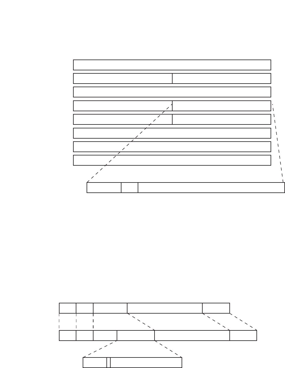
Figure 6- 38. IEEE 802.1Q Tag
The EtherType and VLAN ID are inserted after the MAC source address, but before the original EtherType/Length or Logical Link Control. Because the packet is
now a bit longer than it was originally, the Cyclic Redundancy Check (CRC) must be recalculated.
Figure 6- 39.Adding an IEEE 802.1Q Tag
56
Allied Telesyn AT-9724TS High-Density Layer 3 Stackable Gigabit Ethernet Switch
Octets
0123
IEEE 802.1Q Tag
Destination Address (6 Octets)
Cyclic Redundancy Check (4 Octets)
VLAN ID (VID)
Source Address (6 Octets)
Ether Type = 0x8100 Tag Control Information
MAC Length/Type Beginning of Data
CFIUser Priority
3 bits 1 bit 12 bits
4
Adding an IEEE 802.1 Tag
Length/EType
Dest. Src. Data Old CRC
ETypeDest. Src. Data New CRCTa g
Priority VLAN ID
Original Ethernet Packet
New Tagged Packet

Port VLAN ID
Packets that are tagged (are carrying the 802.1Q VID information) can be transmitted from one 802.1Q compliant network device to another with the VLAN
information intact.This allows 802.1Q VLANs to span network devices (and indeed, the entire network, if all network devices are 802.1Q compliant).
Unfortunately, not all network devices are 802.1Q compliant.These devices are referred to as tag-unaware. 802.1Q devices are referred to as tag-aware.
Prior to the adoption of 802.1Q VLANs, port-based and MAC-based VLANs were in common use.These VLANs relied upon a Port VLAN ID (PVID) to forward
packets.A packet received on a given port would be assigned that port's PVID and then be forwarded to the port that corresponded to the packet's destination
address (found in the Switch's forwarding table). If the PVID of the port that received the packet is different from the PVID of the port that is to transmit the
packet, the Switch will drop the packet.
Within the Switch, different PVIDs mean different VLANs (remember that two VLANs cannot communicate without an external router). So,VLAN identification
based upon the PVIDs cannot create VLANs that extend outside a given switch (or switch stack).
Every physical port on a switch has a PVID. 802.1Q ports are also assigned a PVID, for use within the Switch. If no VLANs are defined on the Switch, all ports are
then assigned to a default VLAN with a PVID equal to 1. Untagged packets are assigned the PVID of the port on which they were received. Forwarding decisions
are based upon this PVID, in so far as VLANs are concerned.Tagged packets are forwarded according to the VID contained within the tag.Tagged packets are also
assigned a PVID, but the PVID is not used to make packet forwarding decisions, the VID is.
Tag-aware switches must keep a table to relate PVIDs within the Switch to VIDs on the network.The Switch will compare the VID of a packet to be transmitted
to the VID of the port that is to transmit the packet. If the two VIDs are different, the Switch will drop the packet. Because of the existence of the PVID for
untagged packets and the VID for tagged packets, tag-aware and tag-unaware network devices can coexist on the same network.
A switch port can have only one PVID, but can have as many VIDs as the Switch has memory in its VLAN table to store them.
Because some devices on a network may be tag-unaware, a decision must be made at each port on a tag-aware device before packets are transmitted – should
the packet to be transmitted have a tag or not? If the transmitting port is connected to a tag-unaware device, the packet should be untagged. If the transmitting
port is connected to a tag-aware device, the packet should be tagged.
Tagging and Untagging
Every port on an 802.1Q compliant switch can be configured as tagging or untagging.
Ports with tagging enabled will put the VID number, priority and other VLAN information into the header of all packets that flow into and out of it. If a packet has
previously been tagged, the port will not alter the packet, thus keeping the VLAN information intact.The VLAN information in the tag can then be used by other
802.1Q compliant devices on the network to make packet-forwarding decisions.
Ports with untagging enabled will strip the 802.1Q tag from all packets that flow into and out of those ports. If the packet doesn't have an 802.1Q VLAN tag, the
port will not alter the packet.Thus, all packets received by and forwarded by an untagging port will have no 802.1Q VLAN information. (Remember that the PVID
is only used internally within the Switch). Untagging is used to send packets from an 802.1Q-compliant network device to a non-compliant network device.
Ingress Filtering
A port on a switch where packets are flowing into the Switch and VLAN decisions must be made is referred to as an ingress port. If ingress filtering is enabled for
a port, the Switch will examine the VLAN information in the packet header (if present) and decide whether or not to forward the packet.
If the packet is tagged with VLAN information, the ingress port will first determine if the ingress port itself is a member of the tagged VLAN. If it is not, the packet
will be dropped. If the ingress port is a member of the 802.1Q VLAN, the Switch then determines if the destination port is a member of the 802.1Q VLAN. If it is
not, the packet is dropped. If the destination port is a member of the 802.1Q VLAN, the packet is forwarded and the destination port transmits it to its attached
network segment.
If the packet is not tagged with VLAN information, the ingress port will tag the packet with its own PVID as a VID (if the port is a tagging port).The switch then
determines if the destination port is a member of the same VLAN (has the same VID) as the ingress port. If it does not, the packet is dropped. If it has the same
VID,the packet is forwarded and the destination port transmits it on its attached network segment.
This process is referred to as ingress filtering and is used to conserve bandwidth within the Switch by dropping packets that are not on the same VLAN as the
ingress port at the point of reception.This eliminates the subsequent processing of packets that will just be dropped by the destination port.
Default VLANs
The Switch initially configures one
VLAN,VID = 1, called "default." The factory default setting assigns all ports on the Switch to the "default." As new VLANs are
configured in Port-based mode, their respective member ports are removed from the "default."
Packets cannot cross VLANs. If a member of one VLAN wants to connect to another VLAN, the link must be through an external router.
Note: If no VLANs are configured on the Switch, then all packets will be forwarded to any destination port. Packets with unknown source
addresses will be flooded to all ports. Broadcast and multicast packets will also be flooded to all ports.
57
Allied Telesyn AT-9724TS High-Density Layer 3 Stackable Gigabit Ethernet Switch

An example is presented below:
VLAN Name VID Switch Ports
System (default) 1 5, 6, 7, 8, 21, 22, 23, 24
Engineering 2 9, 10, 11, 12
Marketing 3 13, 14, 15, 16
Finance 4 17, 18, 19, 20
Sales 5 1, 2, 3, 4
Table 6- 3.VLAN Example – Assigned Ports
Port-based VLANs
Port-based VLANs limit traffic that flows into and out of switch ports.Thus, all devices connected to a port are members of the VLAN(s) the port belongs to,
whether there is a single computer directly connected to a switch, or an entire department.
On port-based VLANs, NICs do not need to be able to identify 802.1Q tags in packet headers. NICs send and receive normal Ethernet packets. If the packet's
destination lies on the same segment, communications take place using normal Ethernet protocols. Even though this is always the case, when the destination for a
packet lies on another switch port,VLAN considerations come into play to decide if the packet gets dropped by the Switch or delivered.
VLAN Segmentation
Take for example a packet that is transmitted by a machine on Port 1 that is a member of VLAN 2. If the destination lies on another port (found through a
normal forwarding table lookup), the Switch then looks to see if the other port (Port 10) is a member of VLAN 2 (and can therefore receive VLAN 2 packets). If
Port 10 is not a member of VLAN 2, then the packet will be dropped by the Switch and will not reach its destination. If Port 10 is a member of VLAN 2, the
packet will go through.This selective forwarding feature based on VLAN criteria is how VLANs segment networks.The key point being that Port 1 will only
transmit on VLAN 2.
Network resources such as printers and servers however, can be shared across VLANs.This is achieved by setting up overlapping VLANs.That is ports can belong
to more than one VLAN group. For example, setting VLAN 1 members to ports 1, 2, 3, and 4 and VLAN 2 members to ports 1, 5, 6, and 7. Port 1 belongs to two
VLAN groups. Ports 8, 9, and 10 are not configured to any VLAN group.This means ports 8, 9, and 10 are in the same VLAN group.
VLAN and Trunk Groups
The members of a trunk group have the same VLAN setting.Any VLAN setting on the members of a trunk group will apply to the other member ports.
Note: In order to use
VLAN segmentation in conjunction with port trunk groups, you can first set the port trunk group(s), and then you may
configure VLAN settings. If you wish to change the port trunk grouping with VLANs already in place, you will not need to reconfigure the VLAN
settings after changing the port trunk group settings.VLAN settings will automatically change in conjunction with the change of the port trunk group
settings.
Protocol VLANs
The AT-9724TS incorporates the idea of protocol-based VLANs.This standard, defined by the IEEE 802.1v standard maps packets to protocol-defined VLANs by
examining the type octet within the packet header to discover the type of protocol associated with it.After assessing the protocol, the Switch will forward the
packets to all ports within the protocol-assigned VLAN.This feature will benefit the administrator by better balancing load sharing and enhancing traffic
classification.The Switch supports fifteen (15) pre-defined protocols for configuration.The user may also choose a protocol that is not one of the fifteen defined
protocols by properly configuring the userDefined protocol VLAN.The supported protocols for the protocol VLAN function on this switch include IP, IPX, DEC,
DEC LAT, SNAP, NetBIOS,AppleTalk, XNS, SNA, IPv6, RARP and VINES.
The following is a list of type headers for each protocol listed for VLAN configuration.
58
Allied Telesyn AT-9724TS High-Density Layer 3 Stackable Gigabit Ethernet Switch

Protocol Type Header in Hexadecimal Form
IP over Ethernet 0x0800
IPX 802.3 0xFFFF
IPX 802.2 0xE0E0
IPX SNAP 0x8137
IPX over Ethernet2 0x8137
DecLAT 0x6000
DecOther 0x6009
SNA 802.2 0x0404
NetBios 0xF0F0
XNS 0x0600
VINES 0x0BAD
IPv6 0x86DD
AppleTalk 0x809B
RARP 0x8035
Table 6- 4. Protocol VLAN and the corresponding type header
In configuring the user-defined protocol, the administrator must make sure that the pre-defined user type header does not match any other type header.A match
may cause discrepancies within the local network and failure to define the VLAN to forward packets to.
Static VLAN Entry
In the Configuration folder,open the VLAN folder and click the Static VLAN Entry link to open the following window:
Figure 6- 40. Current 802.1Q Static VLANs Entries window
59
Allied Telesyn AT-9724TS High-Density Layer 3 Stackable Gigabit Ethernet Switch
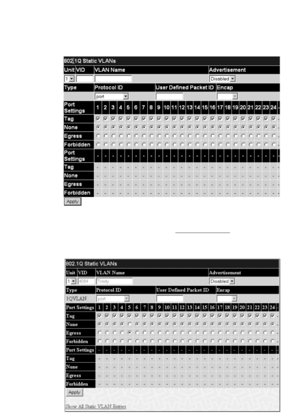
The 802.1Q Static VLANs menu lists all previously configured VLANs by VLAN ID and VLAN Name.To delete an existing 802.1Q VLAN, click the
corresponding button under the Delete heading.
To create a new 802.1Q VLAN, click the Add button in the 802.1Q Static VLANs menu. A new menu will appear, as shown below, to configure the port
settings and to assign a unique name and number to the new VLAN. See the table below for a description of the parameters in the new menu.
Figure 6- 41. 802.1Q Static VLANs – Add
To return to the Current 802.1Q Static VLANs Entries window, click the Show All Static VLAN Entries link.To change an existing 802.1Q VLAN entry,
click the Modify button of the corresponding entry you wish to modify.A new menu will appear to configure the port settings and to assign a unique name and
number to the new VLAN. See the table below for a description of the parameters in the new menu.
Figure 6- 42. 802.1Q Static VLANs – Modify
The following fields can then be set in either the Add or Modify 802.1Q Static VLANs menus:
60
Allied Telesyn AT-9724TS High-Density Layer 3 Stackable Gigabit Ethernet Switch

Parameter Description
Unit Choose the Switch ID number of the Switch in the switch stack to be modified.
VID (VLAN ID) Allows the entry of a VLAN ID in the Add dialog box, or displays the VLAN ID of an existing VLAN in the
Modify dialog box.VLANs can be identified by either the VID or the VLAN name.
VLAN Name Allows the entry of a name for the new VLAN in the Add dialog box, or for editing the VLAN name in the
Modify dialog box.
Advertisement Enabling this function will allow the Switch to send out GVRP packets to outside sources, notifying that they
may join the existing VLAN.
Type Displays the type of protocol associated with this VLAN.
Protocol ID The following parameters allow for the creation of protocol-based VLANs.The Switch supports 15 pre-
configured protocol-based VLANs plus one user-defined protocol based VLAN where the administrator may
configure the settings for the appropriate protocol and forwarding of packets (16 total). Selecting a specific
protocol will indicate which protocol will be utilized in determining the VLAN ownership of a tagged packet.
Pre-set protocol-based VLANs on the switch include:
port – Using this parameter will allow the creation of a normal 802.1Q VLAN on the Switch.
ip – Using this parameter will instruct the Switch to forward packets to this VLAN if the tag in the packet
header is concurrent with this protocol.This packet header information is based on the Ethernet protocol.
rarp – Using this parameter will instruct the Switch to forward packets to this VLAN if the tag in the packet
header is concurrent with this protocol.This packet header information is defined by the Reverse Address
Resolution (RARP) Protocol.
ipx802dot3 – Using this parameter will instruct the Switch to forward packets to this VLAN if the tag in the
packet header is concurrent with this protocol.This packet header information is defined by Novell NetWare
802.3 (IPX - Internet Packet Exchange).
ipx802dot2 – Using this parameter will instruct the Switch to forward packets to this VLAN if the tag in the
packet header is concurrent with this protocol.This packet header information is defined by Novell NetWare
802.2 (IPX - Internet Packet Exchange).
ipxSnap – Using this parameter will instruct the Switch to forward packets to this VLAN if the tag in the packet
header is concurrent with this protocol.This packet header information is defined by Novell and the Sub
Network Access Protocol (SNAP).
ipxEthernet2 – Using this parameter will instruct the Switch to forward packets to this VLAN if the tag in the
packet header is concurrent with this protocol.This packet header information is defined by the Ethernet
Protocol.
AppleTalk – Using this parameter will instruct the Switch to forward packets to this VLAN if the tag in the
packet header is concurrent with this protocol.This packet header information is defined by the AppleTalk
protocol.
decLAT – Using this parameter will instruct the Switch to forward packets to this VLAN if the tag in the packet
header is concurrent with this protocol.This packet header information is defined by the Digital Equipment
Corporation (DEC) Local Area Transport (LAT) protocol.
decOther – Using this parameter will instruct the Switch to forward packets to this VLAN if the tag in the
packet header is concurrent with this protocol.This packet header information is defined by the Digital
Equipment Corporation (DEC) Protocol.
sna802dot2 – Using this parameter will instruct the Switch to forward packets to this VLAN if the tag in the
packet header is concurrent with this protocol.This packet header information is defined by the Systems
Network Architecture(SNA) 802.2 Protocol.
netBios – Using this parameter will instruct the Switch to forward packets to this VLAN if the tag in the packet
header is concurrent with this protocol.This packet header information is defined by the NetBIOS Protocol.
xns – Using this parameter will instruct the Switch to forward packets to this VLAN if the tag in the packet
header is concurrent with this protocol.This packet header information is defined by the Xerox Network
Systems (XNS) Protocol.
vines – Using this parameter will instruct the Switch to forward packets to this VLAN if the tag in the packet
header is concurrent with this protocol.This packet header information is defined by the Banyan Virtual
Integrated Network Service (VINES) Protocol.
ipV6 – Using this parameter will instruct the Switch to forward packets to this VLAN if the tag in the packet
header is concurrent with this protocol.This packet header information is defined by the Internet Protocol
Version 6 (IPv6) Protocol.
userDefined – Using this parameter will instruct the Switch to forward packets to this VLAN if the tag in the
packet header is concurrent with this protocol defined by the user.This packet header information is defined by
entering the following information:
61
Allied Telesyn AT-9724TS High-Density Layer 3 Stackable Gigabit Ethernet Switch

User Defined Pid – Specifies that the VLAN will only accept packets with this hexadecimal 802.1Q Ethernet type
value in the packet header.The user may define an entry, in the hexadecimal form (ffff) to define the packet
identification. (The user only need enter the final four integers of the hexadecimal format to define the packet ID –{hex
0x0 0xffff}) This field is only operable if userDefined is selected in the Protocol ID field.
encap [ethernet | llc | snap | all] – Specifies that the Switch will examine the octet of the packet header referring
to one of the protocols listed (Ethernet, LLC or SNAP), looking for a match of the hexadecimal value
previously entered . all will instruct the Switch to examine the total packet header.After a match is found, the
Switch will forward the packet to this VLAN.This field is only operable if userDefined is selected in the Protocol
ID field.
Port Settings Allows an individual port to be specified as member of a VLAN.
Tag Specifies the port as either 802.1Q tagging or 802.1Q untagged. Checking the box will designate the port as
Tagged.
None Allows an individual port to be specified as a non-VLAN member.
Egress Select this to specify the port as a static member of the VLAN. Egress member ports are ports that will be
transmitting traffic for the VLAN.These ports can be either tagged or untagged.
Forbidden Select this to specify the port as not being a member of the VLAN and that the port is forbidden from
becoming a member of the VLAN dynamically.
Click Apply to implement changes made. Click the Show All Static VLAN Entries link to return to the Current 802.1Q Static VLAN Entries window.
GVRP Setting
In the Configuration menu, open the VLANs folder and click GVRP Setting.
The 802.1Q Port Settings dialog box, shown below, allows you to determine whether the Switch will share its VLAN configuration information with other
GARP VLAN Registration Protocol (GVRP) enabled switches. In addition, Ingress Checking can be used to limit traffic by filtering incoming packets whose
PVID does not match the PVID of the port. Results can be seen in the table under the configuration settings, as seen below.
Figure 6- 43. GVRP Settings and Table window
62
Allied Telesyn AT-9724TS High-Density Layer 3 Stackable Gigabit Ethernet Switch

The following fields can be set:
Parameter Description
Unit Choose the Switch ID number of the Switch in the switch stack to be modified.
From/To These two fields allow you to specify the range of ports that will be included in the Port-based VLAN that you
are creating using the 802.1Q Static VLANs page.
GVRP The Group VLAN Registration Protocol (GVRP) enables the port to dynamically become a member of a VLAN.
GVRP is Disabled by default.
Ingress Check This field can be toggled using the space bar between Enabled and Disabled.Enabled enables the port to
compare the VID tag of an incoming packet with the PVID number assigned to the port. If the two are different,
the port filters (drops) the packet. Disabled disables ingress filtering. Ingress Checking is Disabled by default.
Acceptable Frame Type This field denotes the type of frame that will be accepted by the port.The user may choose between Tagged
Only, which means only VLAN tagged frames will be accepted, and Admit_All, which means both tagged and
untagged frames will be accepted. Admit_All is enabled by default.
PVID The read only field in the GVRP Table shows the current PVID assignment for each port, which may be
manually assigned to a VLAN when created in the 802.1Q Static VLANs table.The Switch's default is to assign
all ports to the default VLAN with a VID of 1.The PVID is used by the port to tag outgoing, untagged packets,
and to make filtering decisions about incoming packets. If the port is specified to accept only tagged frames – as
tagging, and an untagged packet is forwarded to the port for transmission, the port will add an 802.1Q tag using
the PVID to write the VID in the tag.When the packet arrives at its destination, the receiving device will use the
PVID to make VLAN forwarding decisions. If a packet is received by the port, and Ingress filtering is enabled, the
port will compare the VID of the incoming packet to its PVID. If the two are unequal, the port will drop the
packet. If the two are equal, the port will receive the packet.
Click Apply to implement changes made.
6-15 Traffic Control
Use the Traffic Control menu to enable or disable storm control and adjust the threshold for multicast and broadcast storms, as well as DLF (Destination
Look Up Failure).Traffic control settings are applied to individual Switch modules.
To view the following window, click Configuration > Traffic Control:
Figure 6- 44.Traffic Control Settings and Traffic Control Table window
63
Allied Telesyn AT-9724TS High-Density Layer 3 Stackable Gigabit Ethernet Switch

To configure Traffic Control, first select the Switch’s Unit ID number from the pull down menu and then a group of ports by using the Group pull down
menu. Finally, enable or disable the Broadcast Storm,Multicast Storm and Destination Unknown using their corresponding pull-down menus.
The purpose of this window is to limit too many broadcast, multicast or unknown unicast packets folding the network. Each port has a counter that tracks the
number of broadcast packets received per second, and this counter is cleared once every second. If the broadcast, multicast or unknown unicast storm control is
enabled, the port will discard all broadcast, multicast or unknown unicast packets received when the counter exceeds or equals the Threshold specified.
The Threshold value is the upper threshold at which the specified traffic control is switched on.This is the number of Broadcast, Multicast or DLF packets, in
Kpps (kilopackets per second), received by the Switch that will trigger the storm traffic control measures.The Threshold value can be set from 0 to 255
kilopackets per second.The default setting is 128.The settings of each port may be viewed in the Traffic Control Table in the same window. Click Apply to
implement changes made.
6-16 Port Security
A given port's (or a range of ports') dynamic MAC address learning can be locked such that the current source MAC addresses entered into the MAC address
forwarding table can not be changed once the port lock is enabled.The port can be locked by using the Admin State pull-down menu to Enabled, and clicking
Apply.
Port Security is a security feature that prevents unauthorized computers (with source MAC addresses) unknown to the Switch prior to locking the port (or
ports) from connecting to the Switch's locked ports and gaining access to the network.
Figure 6- 45. Port Security Settings and Port Security Table window
The following parameters can be set:
Parameter Description
Unit Choose the Switch ID number of the Switch in the switch stack to be modified.
From/ToA consecutive group of ports may be configured starting with the selected port.
Admin State This pull-down menu allows you to enable or disable Port Security (locked MAC address table for the selected
ports).
Max. Learning Addr. (0-64) The number of MAC addresses that will be in the MAC address forwarding table for the selected switch and
group of ports.
Mode This pull-down menu allows you to select how the MAC address table locking will be implemented on the
Switch, for the selected group of ports.The options are:
Permanent – The locked addresses will not age out after the aging timer expires.
DeleteOnTimeout – The locked addresses will age out after the aging timer expires.
DeleteOnReset – The locked addresses will not age out until the Switch has been reset.
Click Apply to implement changes made.
64
Allied Telesyn AT-9724TS High-Density Layer 3 Stackable Gigabit Ethernet Switch
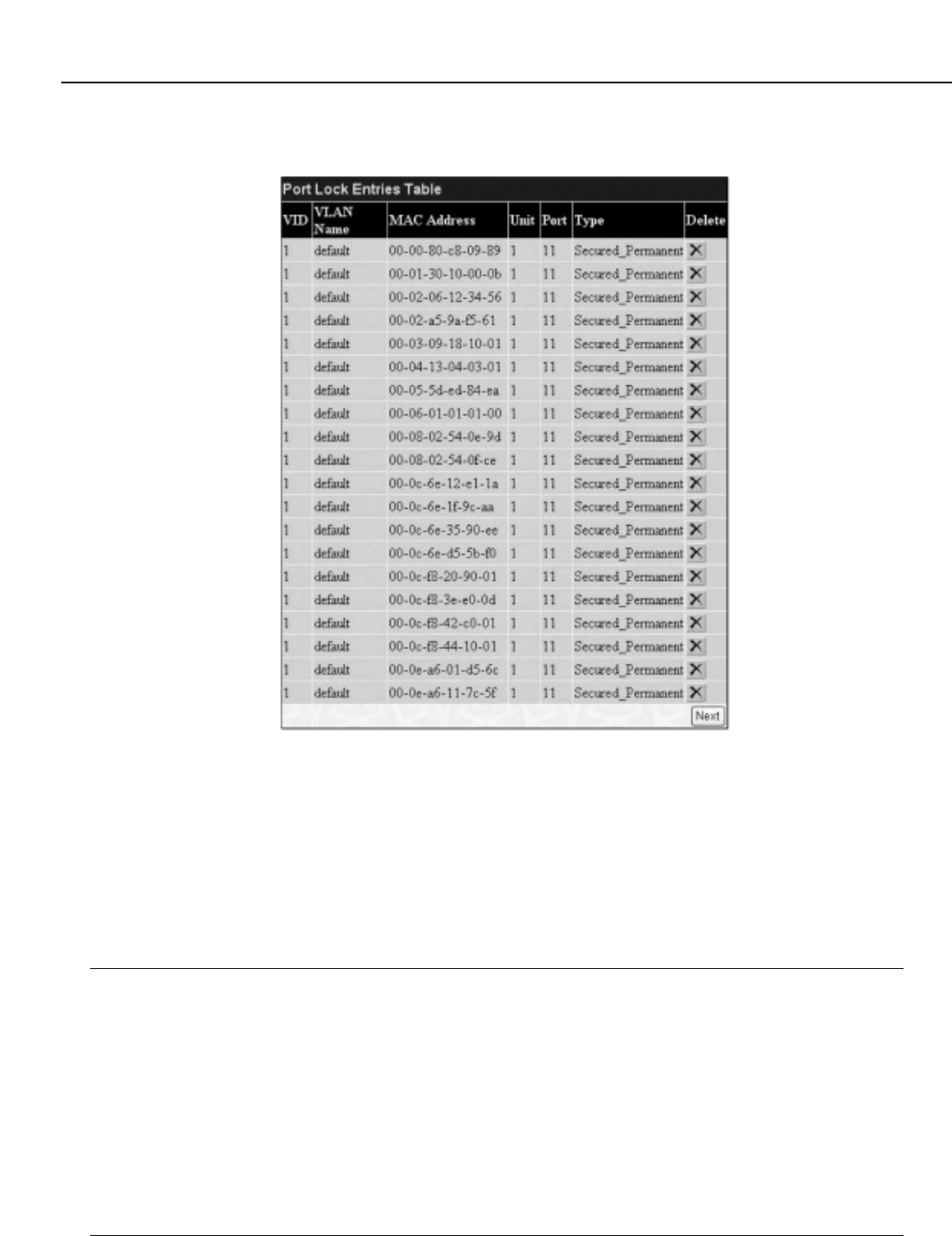
65
Allied Telesyn AT-9724TS High-Density Layer 3 Stackable Gigabit Ethernet Switch
6-17 Port Lock Entries
The Port Lock Entry Delete window is used to remove an entry from the port security entries learned by the Switch and entered into the forwarding
database.To view the following window, click Configuration > Port Lock Entries:
Figure 6- 46. Port Lock Entries Table
This function is only operable if the Mode in the Port Security window is selected as Permanent or DeleteOnReset, or in other words, only addresses
that are permanently learned by the Switch can be deleted. Once the entry has been defined by entering the correct information into the window above, click
the 8 under the Delete heading of the corresponding MAC address to be deleted. Click the Next button to view the next page of entries listed in this table.
This window displays the following information:
Parameter Description
VID The VLAN ID of the entry in the forwarding database table that has been permanently learned by the Switch.
VLAN NAME The VLAN Name of the entry in the forwarding database table that has been permanently learned by the
Switch.
MAC Address The MAC address of the entry in the forwarding database table that has been permanently learned by the
Switch.
Unit The ID number of the Switch in the switch stack that has permanently learned the MAC address.
Port The ID number of the port that has permanently learned the MAC address.
Type The type of MAC address in the forwarding database table. Only entries marked Secured_Permanent can
be deleted.
Delete Click the 8in this field to delete the corresponding MAC address that was permanently learned by the
Switch.

6-18 QoS
The AT-9724TS supports 802.1p priority queuing Quality of Service.The following section discusses the implementation of QoS (Quality of Service) and benefits
of using 802.1p priority queuing.
The Advantages of QoS
QoS is an implementation of the IEEE 802.1p standard that allows network administrators a method of reserving bandwidth for important functions that require
a large bandwidth or have a high priority, such as VoIP (voice-over Internet Protocol), web browsing applications, file server applications or video conferencing.
Not only can a larger bandwidth be created, but other less critical traffic can be limited, so excessive bandwidth can be saved.The Switch has separate hardware
queues on every physical port to which packets from various applications can be mapped to, and, in turn prioritized.View the following map to see how the AT-
9724TS implements 802.1P priority queuing.
Figure 6- 47. Mapping QoS on the Switch
The picture above shows the default priority setting for the Switch. Class-6 has the highest priority of the seven priority classes of service on the Switch. In order
to implement QoS, the user is required to instruct the Switch to examine the header of a packet to see if it has the proper identifying tag tagged.Then the user
may forward these tagged packets to designated classes of service on the Switch where they will be emptied, based on priority.
For example, lets say a user wishes to have a video conference between two remotely set computers.The administrator can add priority tags to the video
packets being sent out, utilizing the Access Profile commands.Then, on the receiving end, the administrator instructs the Switch to examine packets for this tag,
acquires the tagged packets and maps them to a class queue on the Switch.Then in turn, the administrator will set a priority for this queue so that will be
emptied before any other packet is forwarded.This results in the end user receiving all packets sent as quickly as possible, thus prioritizing the queue and allowing
for an uninterrupted stream of packets, which optimizes the use of bandwidth available for the video conference.
Understanding QoS
The Switch has eight priority classes of service, one of which is internal and unconfigurable.These priority classes of service are labelled as 6, the high class to 0,
the lowest class.The eight priority tags, specified in IEEE 802.1p are mapped to the Switch's priority classes of service as follows:
Priority 0 is assigned to the Switch's Q2 class.
Priority 1 is assigned to the Switch's Q0 class.
Priority 2 is assigned to the Switch's Q1 class.
Priority 3 is assigned to the Switch's Q3 class.
Priority 4 is assigned to the Switch's Q4 class.
Priority 5 is assigned to the Switch's Q5 class.
Priority 6 is assigned to the Switch's Q6 class.
Priority 7 is assigned to the Switch's Q6 class.
For strict priority-based scheduling, any packets residing in the higher priority classes of service are transmitted first. Multiple strict priority classes of service are
emptied based on their priority tags. Only when these classes are empty, are packets of lower priority transmitted.
For weighted round-robin queuing, the number of packets sent from each priority queue depends upon the assigned weight. For a configuration of 8 CoS queues,
66
Allied Telesyn AT-9724TS High-Density Layer 3 Stackable Gigabit Ethernet Switch
7 priority queues
How 802.1p works (Switch default settings)
Class 0 Class 1 Class 2 Class 3 Class 4 Class 5 Class 6
Queues
0 1 2 3 45 6 7
Priority
Port1 2 3
Port default
priority
0 0 0 1 4 2 6 .........................................
4 5 6 7 ............................
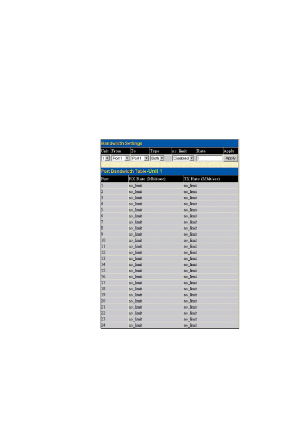
A~H with their respective weight value: 8~1, the packets are sent in the following sequence:A1, B1, C1, D1, E1, F1, G1, H1,A2, B2, C2, D2, E2, F2, G2,A3, B3, C3,
D3, E3, F3,A4, B4, C4, D4, E4,A5, B5, C5, D5,A6, B6, C6,A7, B7,A8,A1, B1, C1, D1, E1, F1, G1, H1.
For weighted round-robin queuing, if each CoS queue has the same weight value, then each CoS queue has an equal opportunity to send packets just like round-
robin queuing.
For weighted round-robin queuing, if the weight for a CoS is set to 0, then it will continue processing the packets from this CoS until there are no more packets
for this CoS.The other CoS queues that have been given a nonzero value, and depending upon the weight, will follow a common weighted round-robin scheme.
Remember that the AT-9724TS has 7 configurable priority queues (and seven Classes of Service) for each port on the Switch.
mCaution: The Switch contains eight classes of service for each port on the Switch. One of these classes is reserved for internal use on the
Switch and is therefore unconfigurable.All references in the following section regarding classes of service will refer to only the seven classes of
service that may be used and configured by the Switch’s Administrator.
Bandwidth Control
The bandwidth control settings are used to place a ceiling on the transmitting and receiving data rates for any selected port. In the Configuration folder, click
Bandwidth Control, to view the screen shown below.
Figure 6- 48. Bandwidth Settings and Port Bandwidth Table
The following parameters can be set or are displayed:
Parameter Description
Unit Choose the Switch ID number of the Switch in the switch stack to be modified.
From/ToA consecutive group of ports may be configured starting with the selected port.
Type This drop-down menu allows you to select between RX (receive,) TX (transmit,) and Both.This setting will
determine whether the bandwidth ceiling is applied to receiving, transmitting, or both receiving and transmitting
packets.
no_limit This drop-down menu allows you to specify that the selected port will have no bandwidth limit. Enabled
disables the limit.
Rate This field allows you to enter the data rate, in Mbit/s, that will be the limit for the selected port.
67
Allied Telesyn AT-9724TS High-Density Layer 3 Stackable Gigabit Ethernet Switch
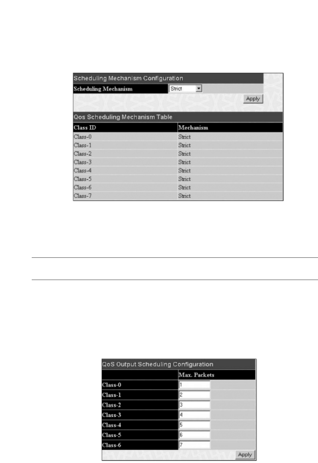
Click Apply to set the bandwidth control for the selected ports. Results of configured Bandwidth Settings will be displayed in the Port Bandwidth
Table.
QoS Scheduling Mechanism
This drop-down menu allows you to select between a Weight Fair and a Strict mechanism for emptying the classes of service. In the Configuration folder
open the QoS folder and click QoS Scheduling Mechanism, to view the screen shown below.
Figure 6- 49. Scheduling Mechanism Configuration and QoS Scheduling Mechanism Table
The Scheduling Mechanism has the following parameters.
Parameter Description
Strict The highest queue is the first to process traffic.That is, the highest queue will finish before other queues empty.
Weight fair Use the weighted round-robin (WRR) algorithm to handle packets in an even distribution in priority queues.
Click Apply to let your changes take effect.
Output Scheduling
QoS can be customized by changing the output scheduling used for the classes of service in the Switch. As with any changes to QoS implementation, careful
consideration should be given to how network traffic in lower classes of service is affected. Changes in scheduling may result in unacceptable levels of packet loss
or significant transmission delay. If you choose to customize this setting, it is important to monitor network performance, especially during peak demand, as
bottlenecks can quickly develop if the QoS settings are not suitable. In the Configuration folder open the QoS folder and click QoS Output Scheduling,
to view the screen shown below.
Figure 6- 50. QoS Output Scheduling Configuration window
68
Allied Telesyn AT-9724TS High-Density Layer 3 Stackable Gigabit Ethernet Switch

You may assign the following values to the QoS classes to set the scheduling.
Parameter Description
Max. Packets Specifies the maximum number of packets the above specified hardware priority queue will be allowed to
transmit before allowing the next lowest priority queue to transmit its packets.A value between 0 and 15 can
be specified.
Click Apply to implement changes made.
Note: Entering a 0 for the Max Packets field in the QoS Output Scheduling Configuration window above will create a Combination
Queue. For more information on implementation of this feature, see the next section, Configuring the Combination Queue.
Configuring the Combination Queue
Utilizing the QoS Output Scheduling Configuration window shown above, the AT-9724TS can implement a combination queue for forwarding packets.
This combination queue allows for a combination of strict and weight-fair (weighted round-robin “WRR”) scheduling for emptying given classes of service.To set
the combination queue, enter a 0 for the Max Packets entry of the corresponding priority classes of service listed in the window above. Priority classes of service
that have a 0 in the Max Packet field will forward packets with strict priority scheduling.The remaining classes of service, that do not have a 0in their Max
Packet field, will follow a weighted round-robin (WRR) method of forwarding packets – as long as the priority classes of service with a 0 in their Max Packet
field are empty.When a packet arrives in a priority class with a 0in its Max Packet field, this class of service will automatically begin forwarding packets until it
is empty. Once a priority class of service with a 0 in its Max Packet field is empty, the remaining priority classes of service will reset the weighted round-robin
(WRR) cycle of forwarding packets, starting with the highest available priority class of service. Priority classes of service with an equal level of priority and equal
entries in their Max Packet field will empty their fields based on hardware priority scheduling.The Max Packet parameter allows you to specify the maximum
number of packets a given priority class of service can transmit per weighted round-robin (WRR) scheduling cycle.This provides for a controllable CoS behavior
while allowing other classes to empty as well.A value between 0 and 15 packets can be specified per priority class of service to create the combination queue.
The example window below displays an example of the combination queue where Class-1 will have a strict priority for emptying its class, while the other classes
will follow a weight fair scheduling.
Figure 6- 51. QoS Output Scheduling Configuration window – Combination queue example
69
Allied Telesyn AT-9724TS High-Density Layer 3 Stackable Gigabit Ethernet Switch

802.1p Default Priority
The Switch allows the assignment of a default 802.1p priority to each port on the Switch. In the Configuration folder open the QoS folder and click 802.1p
Default Priority, to view the screen shown below.
Figure 6- 52. Port Default Priority Assignment and The Port Priority Table window
This page allows you to assign a default 802.1p priority to any given port on the Switch.The priority queues are numbered from 0, the lowest priority, to 7, the
highest priority.To implement a new default priority, choose the Switch of the Switch stack to be configured by using the Unit pull-down menu, choose a port
range by using the From and To pull-down menus and then insert a priority value, from 0-7 in the Priority field. Click Apply to implement your settings.
802.1p User Priority
The AT-9724TS allows the assignment of classes of service to each of the 802.1p priorities. In the Configuration folder open the QoS folder and click
802.1p User Priority, to view the screen shown below.
Figure 6- 53. User Priority Configuration window
70
Allied Telesyn AT-9724TS High-Density Layer 3 Stackable Gigabit Ethernet Switch

Once you have assigned a priority to the port groups on the Switch, you can then assign this Class to each of the7 levels of 802.1p priorities. Click Apply to set
your changes.
Traffic Segmentation
Traffic segmentation is used to limit traffic flow from a single port to a group of ports on either a single Switch (in standalone mode) or a group of ports on
another switch in a switch stack.This method of segmenting the flow of traffic is similar to using VLANs to limit traffic, but is more restrictive. It provides a
method of directing traffic that does not increase the overhead of the Master switch CPU.
In the Configuration folder open the QoS folder and click Traffic Segmentation, to view the screen shown below.
Figure 6- 54. Current Traffic Segmentation Table
Click on the Setup button to open the Setup Forwarding Ports page,as shown below.
Figure 6- 55. Setup Forwarding Ports window
This page allows you to determine which port on a given switch in a switch stack will be allowed to forward packets to other ports on that switch.
Configuring traffic segmentation on the AT-9724TS is accomplished in two parts. First, you specify a switch from a switch stack by using the Unit pull-down
menu, and then a port from that switch, using the Port pull-down menu.Then specify a second switch from the switch stack, and then you select which ports (or
different ports on the same switch,) on that switch that you want to be able to receive packets from the switch and port you specified in the first part.
Clicking the Apply button will enter the combination of transmitting port and allowed receiving ports into the Switch’s Traffic Segmentation table.
The Unit drop-down menu at the top of the page allows you to select a switch from a switch stack using that switch’s Unit ID.The Port drop-down menu
allows you to select a port from that switch.This is the port that will be transmitting packets.
The Unit drop-down menu under the Setup Forwarding ports heading allows you to select a switch from a switch stack using that switch’s Unit ID.The
Forward Port click boxes allow you to select which of the ports on the selected switch will be able to forward packets.These are the ports that will be
allowed to receive packets from the port specified above.
Click Apply to enter the settings into the Switch’s Traffic Segmentation table.
71
Allied Telesyn AT-9724TS High-Density Layer 3 Stackable Gigabit Ethernet Switch

Clicking the Apply button will enter the combination of transmitting port and allowed receiving ports into the Switch's Traffic Segmentation Table.
6-19 System Log Server
The Switch can send Syslog messages to up to four designated servers using the System Log Server. In the Configuration folder, click System Log
Server, to view the screen shown below.
Figure 6- 56. System Log Servers window
The parameters configured for adding and editing System Log Server settings are the same.To add a new Syslog Server, click the Add button.To modify a
current entry, click the hyperlinked number of the server in the Index field. Both actions will result in the same screen to configure. See the table below for a
description of the parameters in the following window.
Figure 6- 57. System Log Servers – Add
The following parameters can be set:
72
Allied Telesyn AT-9724TS High-Density Layer 3 Stackable Gigabit Ethernet Switch

Parameter Description
Index Syslog server settings index (1-4).
Server IP The IP address of the Syslog server.
Severity This drop-down menu allows you to select the level of messages that will be sent.The options are Warning,
Informational, and All.
Facility Some of the operating system daemons and processes have been assigned Facility values. Processes and
daemons that have not been explicitly assigned a Facility may use any of the "local use" facilities or they may use
the "user-level" Facility.Those Facilities that have been designated are shown in the following: Bold font
denotes the facility values that the Switch currently implements.
Numerical Code Facility
0 kernel messages
1 user-level messages
2 mail system
3 system daemons
4 security/authorization messages
5 messages generated internally by syslog line printer subsystem
7 network news subsystem
8 UUCP subsystem
9 clock daemon
10 security/authorization messages
11 FTP daemon
12 NTP subsystem
13 log audit
14 log alert
15 clock daemon
16 local use 0 (local0)
17 local use 1 (local1)
18 local use 2 (local2)
19 local use 3 (local3)
20 local use 4 (local4)
21 local use 5 (local5)
22 local use 6 (local6)
23 local use 7 (local7)
UDP Port (514 or 6000-65535) Type the UDP port number used for sending Syslog messages.The default is 514.
Status Choose Enabled or Disabled to activate or deactivate.
T
o set the System Log Server configuration, click Apply.T
o delete an entry from the Current System Log Server window,click the corresponding 8
under the Delete heading of the entry to delete.To return to the Current System Log Servers window, click the Show All System Log Servers link.
73
Allied Telesyn AT-9724TS High-Density Layer 3 Stackable Gigabit Ethernet Switch
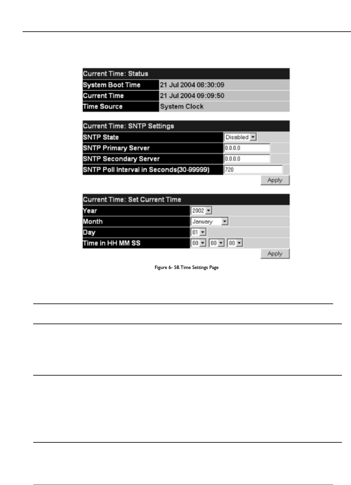
6-20 SNTP Settings
Current Time Settings
To configure the time settings for the Switch, open the Configuration folder, then the SNTP folder and click on the Current Time Setting link, revealing
the following screen for the user to configure.
Figure 6- 58.Time Settings Page
The following parameters can be set or are displayed:
Parameter Description
Current Time: Status
System Boot Time Displays the time when the Switch was initially started for this session.
Current Time Displays the current time.
Time Source Displays the source of the time settings viewed here.
Current Time: SNTP Settings
SNTP State Use this pull-down menu to Enable or Disable SNTP.
SNTP Primary Server This is the IP address of the primary server the SNTP information will be taken from.
SNTP Secondary Server This is the IP address of the secondary server the SNTP information will be taken from.
SNTP Poll Interval in Seconds This is the interval, in seconds, between requests for updated SNTP information.
(30-99999)
Current Time: Set Current Time
Year Enter the current year, if you want to update the system clock.
Month Enter the current month, if you would like to update the system clock.
Day Enter the current day, if you would like to update the system clock.
Time in HH MM SS Enter the current time in hours and minutes, if you would like to update the system clock.
Click Apply to implement your changes.
74
Allied Telesyn AT-9724TS High-Density Layer 3 Stackable Gigabit Ethernet Switch

Time Zone and DST
The following are screens used to configure time zones and Daylight Savings time settings for SNTP. Open the Configuration folder, then the SNTP folder
and click on the Time Zone and DST link, revealing the following screen.
Figure 6- 59.Time Zone and DST Settings Page
The following parameters can be set:
Parameter Description
Daylight Saving Time State Use this pull-down menu to Enable or Disable the DST Settings.
Daylight Saving Time Offset Use this pull-down menu to specify the amount of time that will constitute your local DST offset - 30, 60, 90, or
in Minutes 120 minutes.
Time Zone Offset from GMT in Use these pull-down menus to specify your local time zone's offset from Greenwich Mean Time (GMT.)
+/- HH:MM
DST Repeating Settings Using repeating mode will enable DST seasonal time adjustment. Repeating mode requires that the DST
beginning and ending date be specified using a formula. For example, specify to begin DST on Saturday during
the second week of April and end DST on Sunday during the last week of October.
From: Which Day Enter the week of the month that DST will start.
From: Day of Week Enter the day of the week that DST will start on.
From: Month Enter the month DST will start on.
From: Time in HH:MM Enter the time of day that DST will start on.
To: Which Day Enter the week of the month the DST will end.
To: Day of Week Enter the day of the week that DST will end.
To: Month Enter the month that DST will end.
To: time in HH:MM Enter the time DST will end.
DST Annual Settings Using annual mode will enable DST seasonal time adjustment.Annual mode requires that the DST beginning and
ending date be specified concisely. For example, specify to begin DST on April 3 and end DST on October 14.
From: Month Enter the month DST will start on, each year.
From: Day Enter the day of the month DST will start on, each year.
From: Time in HH:MM Enter the time of day DST will start on, each year.
To: Month Enter the month DST will end on, each year.
To: Day Enter the day of the month DST will end on, each year.
To: Time in HH:MM Enter the time of day that DST will end on, each year.
Click Apply to implement changes made to the Time Zone and DST window.
75
Allied Telesyn AT-9724TS High-Density Layer 3 Stackable Gigabit Ethernet Switch

6-21 Access Profile Table
Configuring the Access Profile Table
Access profiles allow you to establish criteria to determine whether or not the Switch will forward packets based on the information contained in each packet's
header.These criteria can be specified on a basis of VLAN, MAC address or IP address.
Creating an access profile is divided into two basic parts.The first is to specify which part or parts of a frame the Switch will examine, such as the MAC source
address or the IP destination address.The second part is entering the criteria the Switch will use to determine what to do with the frame.The entire process is
described below in two parts.
To display the currently configured Access Profiles on the Switch, open the Configuration folder and click on the Access Profile Table link.This will open
the Access Profile Table page, as shown below.
Figure 6- 60.Access Profile Table
To add an entry to the Access Profile Table, click the Add button.This will open the Access Profile Configuration page, as shown below.There are
three Access Profile Configuration pages; one for Ethernet (or MAC address-based) profile configuration, one for IP address-based profile configuration
and one for the Packet Content Mask.You can switch between the three Access Profile Configuration pages by using the Type drop-down menu.
The page shown below is the Ethernet Access Profile Configuration page.
Figure 6- 61.Access Profile Table (Ethernet)
76
Allied Telesyn AT-9724TS High-Density Layer 3 Stackable Gigabit Ethernet Switch
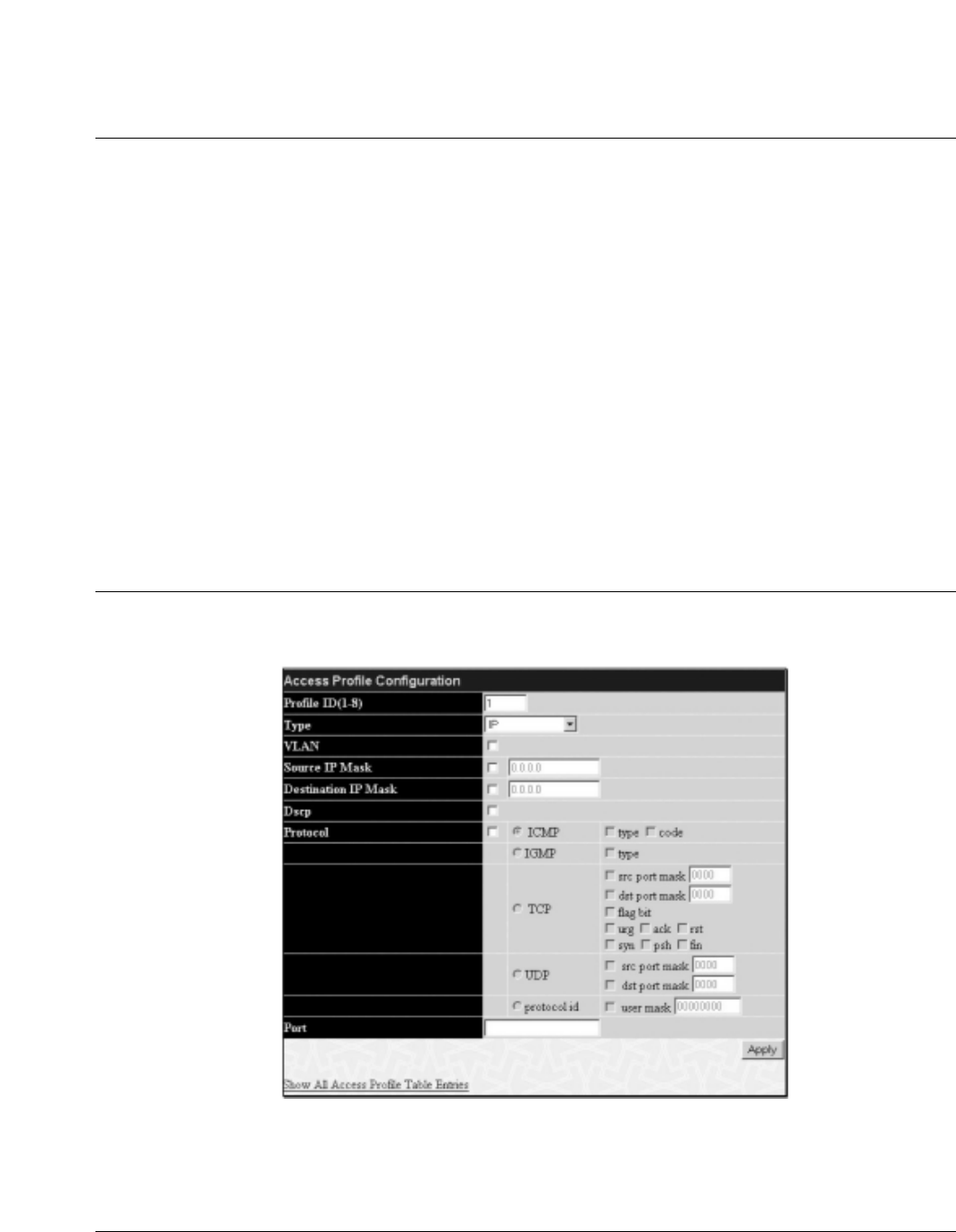
The following parameters can be set, for the Ethernet type:
Parameter Description
Profile ID (1-8) Type in a unique identifier number for this profile set.This value can be set from 1 - 8.
Type Select profile based on Ethernet (MAC Address), IP address or packet content mask.This will change the menu
according to the requirements for the type of profile.
Select Ethernet to instruct the Switch to examine the layer 2 part of each packet header.
Select IP to instruct the Switch to examine the IP address in each frame's header.
Select Packet Content Mask to specify a mask to hide the content of the packet header.
VLAN Selecting this option instructs the Switch to examine the VLAN identifier of each packet header and use this as
the full or partial criterion for forwarding.
Source MAC Source MAC Mask – Enter a MAC address mask for the source MAC address.
Destination MAC Destination MAC Mask – Enter a MAC address mask for the destination MAC address.
802.1p Selecting this option instructs the Switch to examine the 802.1p priority value of each packet header and use
this as the, or part of the criterion for forwarding.
Ethernet type Selecting this option instructs the Switch to examine the Ethernet type value in each frame's header.
Port The user may set the Access Profile Table on a per-port basis by entering a port number in this field.The port
list is specified by listing the lowest switch number and the beginning port number on that switch, separated by
a colon.Then the highest switch number, and the highest port number of the range (also separated by a colon)
are specified.The beginning and end of the port list range are separated by a dash. For example, 1:3 specifies
switch number 1, port 3. 2:4 specifies switch number 2, port 4. 1:3 -2:4 specifies all of the ports between switch
1, port 3 and switch 2, port 4 • in numerical order. Entering all will denote all ports on the Switch.
The page shown below is the IP Access Profile Configuration page.
Figure 6- 62.Access Profile Configuration (IP)
The following parameters can be set, for IP:
Parameter Description
Profile ID (1-8) Type in a unique identifier number for this profile set.This value can be set from 1 - 8.
Type Select profile based on Ethernet (MAC Address), IP address or packet content mask.This will change the menu
according to the requirements for the type of profile.
Select Ethernet to instruct the Switch to examine the layer 2 part of each packet header.
Select IP to instruct the Switch to examine the IP address in each frame's header.
Select Packet Content Mask to specify a mask to hide the content of the packet header.
VLAN Selecting this option instructs the Switch to examine the VLAN part of each packet header and use this as the,
or part of the criterion for forwarding.
77
Allied Telesyn AT-9724TS High-Density Layer 3 Stackable Gigabit Ethernet Switch

Source IP Mask Enter an IP address mask for the source IP address.
Destination IP Mask Enter an IP address mask for the destination IP address.
DSCP Selecting this option instructs the Switch to examine the DiffServ Code part of each packet header and use this
as the, or part of the criterion for forwarding.
Protocol Selecting this option instructs the Switch to examine the protocol type value in each frame's header.You must
then specify what protocol(s) to include according to the following guidelines:
Select ICMP to instruct the Switch to examine the Internet Control Message Protocol (ICMP) field in each
frame's header.
Select Type to further specify that the access profile will apply an ICMP type value, or specify Code
to further specify that the access profile will apply an ICMP code value.
Select IGMP to instruct the Switch to examine the Internet Group Management Protocol (IGMP) field in each
frame's header.
Select Type to further specify that the access profile will apply an IGMP type value.
Select TCP to use the TCP port number contained in an incoming packet as the forwarding criterion. Selecting
TCP requires that you specify a source port mask and/or a destination port mask.The user may also identify
which flag bits to filter. Flag bits are parts of a packet that determine what to do with the packet.The user may
filter packets by filtering certain flag bits within the packets, by checking the boxes corresponding to the flag
bits of the TCP field.The user may choose between urg (urgent), ack (acknowledgement), psh (push), rst
(reset), syn (synchronize), fin (finish).
src port mask – Specify a TCP port mask for the source port in hex form (hex 0x0-0xffff), which
you wish to deny.
dest port mask – Specify a TCP port mask for the destination port in hex form (hex 0x0-0xffff)
which you wish to deny.
Select UDP to use the UDP port number contained in an incoming packet as the forwarding criterion.
Selecting UDP requires that you specify a source port mask and/or a destination port mask.
src port mask – Specify a TCP port mask for the source port in hex form (hex 0x0-0xffff).
dest port mask – Specify a TCP port mask for the destination port in hex form (hex 0x0-0xffff).
protocol id – Enter a value defining the protocol ID in the packet header to mask. Specify the protocol ID
mask in hex form (hex 0x0-0xffffffff).
Port The user may set the Access Profile Table on a per-port basis by entering an entry in this field. Entering all will
denote all ports on the Switch.The port list is specified by listing the lowest switch number and the beginning
port number on that switch, separated by a colon.Then the highest switch number, and the highest port
number of the range (also separated by a colon) are specified.The beginning and end of the port list range are
separated by a dash. For example, 1:3 specifies switch number 1, port 3. 2:4 specifies switch number 2, port 4.
1:3 - 2:4 specifies all of the ports between switch 1, port 3 and switch 2, port 4 •in numerical order. Entering all
will denote all ports on the Switch.
The page shown below is the Packet Content Mask configuration window.
Figure 6- 63.Access Profile Configuration window (Packet Content Mask)
78
Allied Telesyn AT-9724TS High-Density Layer 3 Stackable Gigabit Ethernet Switch

79
Allied Telesyn AT-9724TS High-Density Layer 3 Stackable Gigabit Ethernet Switch
This screen will aid the user in configuring the Switch to mask packet headers beginning with the offset value specified.The following fields are used to configure
the Packet Content Mask:
Parameter Description
Profile ID (1-8) Type in a unique identifier number for this profile set.This value can be set from 1 - 8.
Type Select profile based on Ethernet (MAC Address), IP address or packet content mask.This will change the menu
according to the requirements for the type of profile.
Select Ethernet to instruct the Switch to examine the layer 2 part of each packet header.
Select IP to instruct the Switch to examine the IP address in each frame's header.
Select Packet Content Mask to specify a mask to hide the content of the packet header.
Offset This field will instruct the Switch to mask the packet header beginning with the offset value specified:
value (0-15) - Enter a value in hex form to mask the packet from the beginning of the packet to the 15th byte.
value (16-31) – Enter a value in hex form to mask the packet from byte 16 to byte 31.
value (32-47) – Enter a value in hex form to mask the packet from byte 32 to byte 47.
value (48-63) – Enter a value in hex form to mask the packet from byte 48 to byte 63.
value (64-79) – Enter a value in hex form to mask the packet from byte 64 to byte 79.
Port The user may set the Access Profile Table on a per-port basis by entering an entry in this field. Entering all will
denote all ports on the Switch.The port list is specified by listing the lowest switch number and the beginning
port number on that switch, separated by a colon.Then the highest switch number, and the highest port
number of the range (also separated by a colon) are specified.The beginning and end of the port list range are
separated by a dash. For example, 1:3 specifies switch number 1, port 3. 2:4 specifies switch number 2, port 4.
1:3 - 2:4 specifies all of the ports between switch 1, port 3 and switch 2, port 4 •in numerical order. Entering all
will denote all ports on the Switch.
Click Apply to implement changes made.
To establish the rule for a previously created Access Profile:
In the Configuration folder, click the Access Profile Table link opening the Access Profile Table.Under the heading Access Rule, clicking Modify,
will open the following window.
Figure 6- 64.Access Rule Table window – IP
T
o create a new rule set for an access profile click the Add button. A new window is displayed.To remove a previously created rule, click the corresponding 8
button.
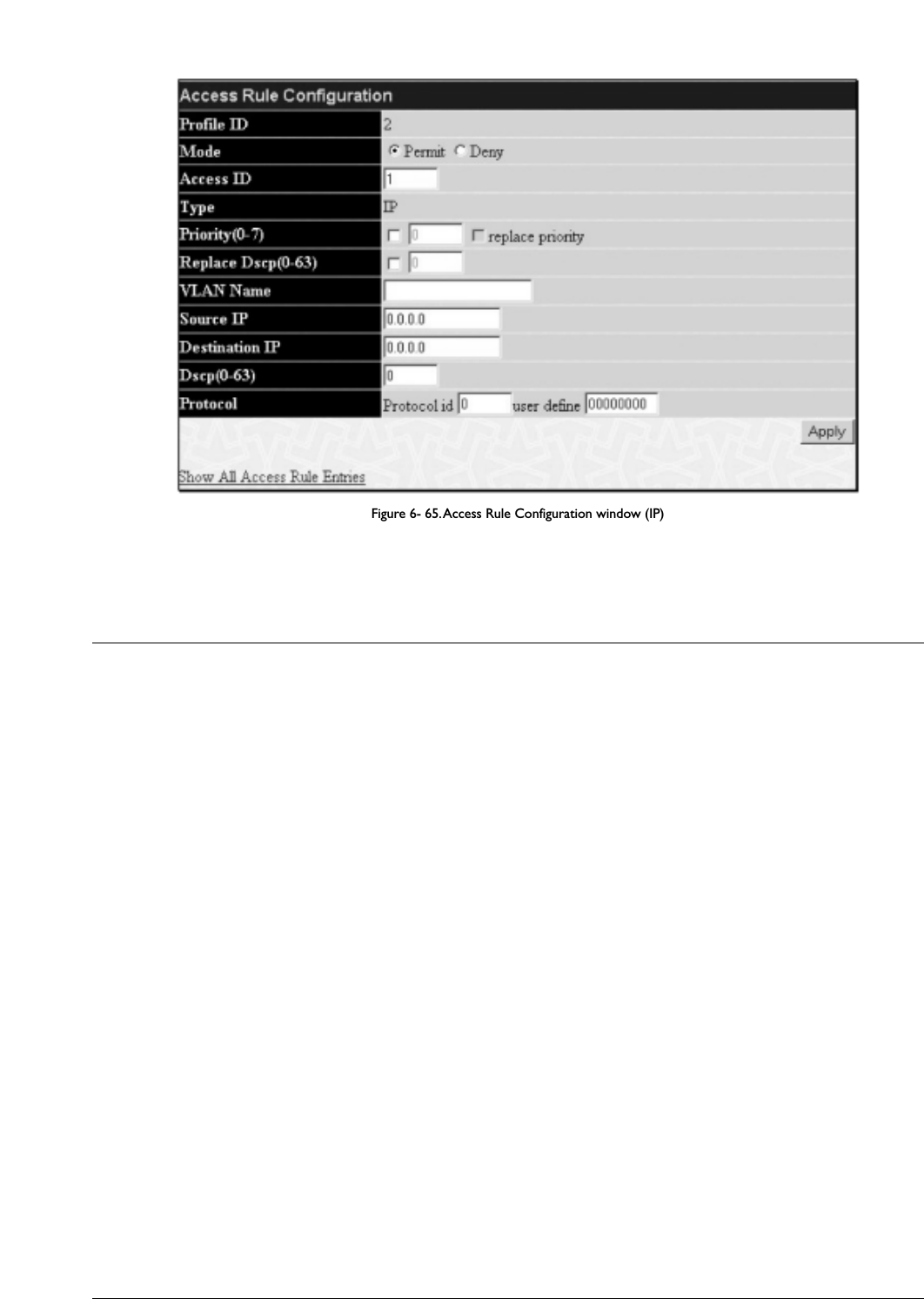
Figure 6- 65.Access Rule Configuration window (IP)
Configure the following Access Rule Configuration settings for IP:
Parameter Description
Profile ID This is the identifier number for this profile set.
Mode Select Permit to specify that the packets that match the access profile are forwarded by the Switch, according
to any additional rule added (see below).
Select Deny to specify that packets that do not match the access profile are not forwarded by the Switch and
will be filtered.
Access ID Type in a unique identifier number for this access.This value can be set from 1-50.
Type Selected profile based on Ethernet (MAC Address), IP address or Packet Content Mask.
Ethernet instructs the Switch to examine the layer 2 part of each packet header.
IP instructs the Switch to examine the IP address in each frame's header.
Packet Content Mask instructs the Switch to examine the packet header.
Priority (0-7) This parameter is specified if you want to re-write the 802.1p default priority previously set in the Switch,
which is used to determine the CoS queue to which packets are forwarded to. Once this field is specified,
packets accepted by the Switch that match this priority are forwarded to the CoS queue specified previously by
the user.
Replace priority with – Click the corresponding box if you want to re-write the 802.1p default priority of a
packet to the value entered in the Priority field, which meets the criteria specified previously in this
command, before forwarding it on to the specified CoS queue. Otherwise, a packet will have its incoming
802.1p user priority re-written to its original value before being forwarded by the Switch. For more
information on priority queues, CoS queues and mapping for 802.1p, see the QoS section of this manual.
Replace Dscp (0-63) Select this option to instruct the Switch to replace the DSCP value (in a packet that meets the selected
criteria) with the value entered in the adjacent field.
VLAN Name Allows the entry of a name for a previously configured
VLAN.
Source IP Enter an IP Address mask for the source IP address.
Destination IP Enter an IP Address mask for the destination IP address.
Dscp (0-63) This field allows the user to enter a DSCP value in the space provided, which will instruct the Switch to
examine the DiffServ Code part of each packet header and use this as the, or part of the criterion for
forwarding.The user may choose a value between 0 and 63.
Protocol This field allows the user to modify the protocol used to configure the Access Rule Table; depending on which
protocol the user has chosen in the Access Profile Table.
To view the settings of a previously correctly configured rule, click Viewin the Access Rule Table to view the following screen:
80
Allied Telesyn AT-9724TS High-Density Layer 3 Stackable Gigabit Ethernet Switch

Figure 6- 66.Access Rule Display window (IP)
To configure the Access Rule for Ethernet, open the Access Profile Table and click Modify for an Ethernet entry.This will open the following screen:
Figure 6- 67.Access Rule Table
To remove a previously created rule, select it and click the 8 button.To add a new Access Rule, click the Add button:
Figure 6- 68.Access Rule Configuration window – Ethernet
To set the Access Rule for Ethernet, adjust the following parameters and click Apply.
81
Allied Telesyn AT-9724TS High-Density Layer 3 Stackable Gigabit Ethernet Switch

Parameter Description
Profile ID This is the identifier number for this profile set.
Mode Select Permit to specify that the packets that match the access profile are forwarded by the Switch, according
to any additional rule added (see below).
Select Deny to specify that packets that do not match the access profile are not forwarded by the Switch and
will be filtered.
Access ID Type in a unique identifier number for this access.This value can be set from 1 - 50.
Type Selected profile based on Ethernet (MAC Address), IP address or Packet Content Mask.
Ethernet instructs the Switch to examine the layer 2 part of each packet header.
IP instructs the Switch to examine the IP address in each frame's header.
Packet Content Mask instructs the Switch to examine the packet header
Priority (0-7) This parameter is specified if you want to re-write the 802.1p default priority previously set in the Switch,
which is used to determine the CoS queue to which packets are forwarded to. Once this field is specified,
packets accepted by the Switch that match this priority are forwarded to the CoS queue specified previously by
the user.
Replace priority with – Click the corresponding box if you want to re-write the 802.1p default priority of a
packet to the value entered in the Priority field, which meets the criteria specified previously in this
command, before forwarding it on to the specified CoS queue. Otherwise, a packet will have its incoming
802.1p user priority re-written to its original value before being forwarded by the Switch.
For more information on priority queues, CoS queues and mapping for 802.1p, see the QoS section of this
manual.
VLAN Name Allows the entry of a name for a previously configured VLAN.
Source MAC Source Enter a MAC Address for the source MAC address.
Destination MAC Destination Enter a MAC Address mask for the destination MAC address.
802.1p (0-7) Enter a value from 0-7 to specify that the access profile will apply only to packets with this 802.1p priority
value.
Ethernet Type Specifies that the access profile will apply only to packets with this hexadecimal 802.1Q Ethernet type value
(hex 0x0-0xffff) in the packet header.The Ethernet type value may be set in the form: hex 0x0-0xffff, which
means the user may choose any combination of letters and numbers ranging from a-f and from 0-9999.
To view the settings of a previously correctly configured rule, click View in the Access Rule Table to view the following screen:
Figure 6- 69.Access Rule Display window (Ethernet)
To configure the Access Rule for Packet Content Mask, open the Access Profile Table and click Modify for a Packet Content Mask entry.This
will open the following screen:
82
Allied Telesyn AT-9724TS High-Density Layer 3 Stackable Gigabit Ethernet Switch

Figure 6- 70.Access Rule Table (Packet Content Mask)
To remove a previously created rule, select it and click the 8 button.To add a new Access Rule, click the Add button:
Figure 6- 71.Access Rule Configuration – Packet Content Mask
To set the Access Rule for the Packet Content Mask, adjust the following parameters and click Apply.
Parameter Description
Profile ID This is the identifier number for this profile set.
Mode Select Permit to specify that the packets that match the access profile are forwarded by the Switch, according
to any additional rule added (see below).
Select Deny to specify that packets that do not match the access profile are not forwarded by the Switch and
will be filtered.
Access ID Type in a unique identifier number for this access.This value can be set from 1 - 50.
Type Selected profile based on Ethernet (MAC Address), IP address or Packet Content Mask.
Ethernet instructs the Switch to examine the layer 2 part of each packet header.
IP instructs the Switch to examine the IP address in each frame's header.
Packet Content Mask instructs the Switch to examine the packet header.
83
Allied Telesyn AT-9724TS High-Density Layer 3 Stackable Gigabit Ethernet Switch
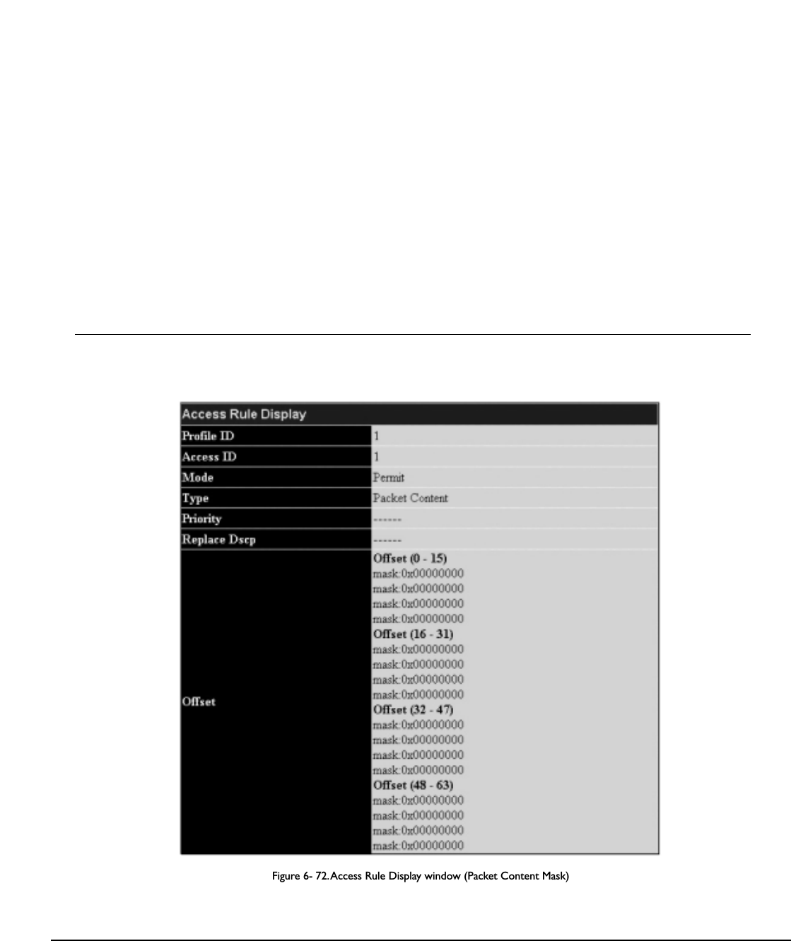
Priority This parameter is specified if you want to re-write the 802.1p default priority previously set in the Switch,
which is used to determine the CoS queue to which packets are forwarded to. Once this field is specified,
packets accepted by the Switch that match this priority are forwarded to the CoS queue specified previously by
the user.
Replace priority with – Click the corresponding box if you want to re-write the 802.1p default priority of a
packet to the value entered in the Priority field, which meets the criteria specified previously in this
command, before forwarding it on to the specified CoS queue. Otherwise, a packet will have its incoming
802.1p user priority re-written to its original value before being forwarded by the Switch.
For more information on priority queues, CoS queues and mapping for 802.1p, see the QoS section of this
manual.
Offset This field will instruct the Switch to mask the packet header beginning with the offset value specified:
value (0-15) – Enter a value in hex form to mask the packet from the beginning of the packet to the 15th byte.
value (16-31) – Enter a value in hex form to mask the packet from byte 16 to byte 31.
value (32-47) – Enter a value in hex form to mask the packet from byte 32 to byte 47.
value (48-63) – Enter a value in hex form to mask the packet from byte 48 to byte 63.
value (64-79) – Enter a value in hex form to mask the packet from byte 64 to byte 79.
To view the settings of a previously correctly configured rule, click View in the Access Rule Table to view the following screen:
Figure 6- 72.Access Rule Display window (Packet Content Mask)
6-22 Port Access Entity (802.1x)
Understanding 802.1x Port-based and MAC-based Network Access Control
The original intent behind the development of 802.1X was to leverage the characteristics of point-to-point connections associated with UTP based LANs.All
single LAN segment in such infrastructures has no more than two devices attached to it, one of which is a Bridge Port.The Bridge Port detects events that
indicate the attachment of an active device at the remote end of the link, or an active device becoming inactive.These events can be used to control the
authorization state of the Port and initiate the process of authenticating the attached device if the Port is unauthorized.This is the Port-Based Network Access
Control.
84
Allied Telesyn AT-9724TS High-Density Layer 3 Stackable Gigabit Ethernet Switch

Port-Based Network Access Control
Figure 6- 73. Example of Typical Port-Based Configuration
Once the connected device has successfully been authenticated, the Port then becomes Authorized, and all subsequent traffic on the Port is not subject to access
control restriction until an event occurs that causes the Port to become Unauthorized. Hence, if the Port is actually connected to a shared media LAN segment
with more than one attached device, successfully authenticating one of the attached devices effectively provides access to the LAN for all devices on the shared
segment. Clearly, the security offered in this situation is open to attack.
MAC-Based Network Access Control
Figure 6- 74. Example of Typical MAC-Based Configuration
In order to successfully make use of 802.1X in a shared media LAN segment, it would be necessary to create “logical” Ports, one for each attached device that
required access to the LAN.The Switch would regard the single physical Port connecting it to the shared media segment as consisting of a number of distinct
logical Ports, each logical Port being independently controlled from the point of view of EAPOL exchanges and authorization state.The Switch learns each
attached devices’ individual MAC addresses, and effectively creates a logical Port that the attached device can then use to communicate with the LAN via the
Switch.
85
Allied Telesyn AT-9724TS High-Density Layer 3 Stackable Gigabit Ethernet Switch
AT-9724TS Switch
Uncontrolled Port
Controlled Port - port blocked
RADIUS
Server
802.1X
Client
802.1X
Client
802.1X
Client
802.1X
Client
802.1X
Client
802.1X
Client
802.1X
Client
802.1X
Client
802.1X
Client
AT-9724TS Switch
802.1X Client802.1X Client802.1X Client 802.1X Client RADIUS
Server
Uncontrolled Port
Controlled Port - port blocked

Configure Authenticator
To configure the 802.1X Authenticator Settings, click PAE Access Entity > Configure Authenticator:
Figure 6- 75. 802.1X Authenticator Settings window
To view the 802.1X Authenticator settings on a different switch in the switch stack, use the Unit pull-down menu to select that switch by its ID number in the
switch stack.To configure the settings by port, click on the hyperlinked port number under the Port heading, which will display the following table to configure:
Figure 6- 76. 802.1X Authenticator Settings – Modify
86
Allied Telesyn AT-9724TS High-Density Layer 3 Stackable Gigabit Ethernet Switch

This screen allows you to set the following features:
Parameter Description
Unit Choose the Switch ID number of the Switch in the switch stack to be modified.
From [ ] To [ ] Enter the port or ports to be set.
AdmCtrlDir Sets the administrative-controlled direction to either in or both.
If in is selected, control is only exerted over incoming traffic through the port you selected in the first field.
If both is selected, control is exerted over both incoming and outgoing traffic through the controlled port
selected in the first field.
PortControl This allows you to control the port authorization state.
Select forceAuthorized to disable 802.1X and cause the port to transition to the authorized state without any
authentication exchange required.This means the port transmits and receives normal traffic without 802.1X-
based authentication of the client.
If forceUnauthorized is selected, the port will remain in the unauthorized state, ignoring all attempts by the client
to authenticate.The Switch cannot provide authentication services to the client through the interface.
If Auto is selected, it will enable 802.1X and cause the port to begin in the unauthorized state, allowing only
EAPOL frames to be sent and received through the port.The authentication process begins when the link state
of the port transitions from down to up, or when an EAPOL-start frame is received.The Switch then requests
the identity of the client and begins relaying authentication messages between the client and the authentication
server.
The default setting is Auto.
TxPeriod This sets the TxPeriod of time for the authenticator PAE state machine.This value determines the period of
an EAP Request/Identity packet transmitted to the client.The default setting is 30 seconds.
QuietPeriod This allows you to set the number of seconds that the Switch remains in the quiet state following a failed
authentication exchange with the client.The default setting is 60 seconds.
SuppTimeout This value determines timeout conditions in the exchanges between the Authenticator and the client.The
default setting is 30 seconds.
ServerTimeout This value determines timeout conditions in the exchanges between the Authenticator and the authentication
server.The default setting is 30 seconds.
MaxReq The maximum number of times that the Switch will retransmit an EAP Request to the client before it times out
of the authentication sessions.The default setting is 2.
ReAuthPeriod A constant that defines a nonzero number of seconds between periodic reauthentication of the client.The
default setting is 3600 seconds.
ReAuth Determines whether regular reauthentication will take place on this port.The default setting is Disabled.
Click Apply to implement your configuration changes.T
o view configurations for the 802.1X Authenticator Settings on a port-by-port basis, see the
802.1X Authenticator Settings table.
Local Users
In the configuration folder,open the Port Access Entity folder and click Local usersto open the 802.1x Local User Table Configuration window.
This window will allow the user to set different local users on the Switch.
Figure 6- 77. 802.1x Local User Table Configuration and 802.1x Local User Table window
Enter a User Name,Password and confirmation of that password. Properly configured local users will be displayed in the 802.1x Local User Table in
the same window.
87
Allied Telesyn AT-9724TS High-Density Layer 3 Stackable Gigabit Ethernet Switch

PAE System Control
Existing 802.1x port settings are displayed and can be configured using the windows below.
Port Capability Settings
Click Port Access Entity > PAE System Control > 802.1X Capability Settings to view the following window:
Figure 6- 78. 802.1x Capability Settings and Table window
To set up the Switch's 802.1x port-based authentication, select the switch in the switch stack by using the Unit pull-down menu and then select which ports are
to be configured in the From and To fields. Next, enable the ports by selecting Authenticator from the drop-down menu under Capability. Click Apply to let
your change take effect.
Configure the following 802.1x capability settings:
Parameter Description
Unit Choose the Switch ID number of the Switch in the switch stack to be modified.
From and To Ports being configured for 802.1x settings.
Capability T
wo role choices can be selected:
Authenticator – A user must pass the authentication process to gain access to the network.
None – The port is not controlled by the 802.1x functions.
88
Allied Telesyn AT-9724TS High-Density Layer 3 Stackable Gigabit Ethernet Switch

Initializing Ports for Port Based 802.1x
Existing 802.1x port settings are displayed and can be configured using the window below.
Note: Ensure Port Based 802.1x is enabled under Configuration > Advanced Settings.
Click Port Access Entity > PAE System Control > Initialize Port(s) to open the following window:
Figure 6- 79. Initialize Port window (Port-based)
This window allows you to initialize a port or group of ports.The Initialize Port Table in the bottom half of the window displays the current status of the
port(s).
This window displays the following information:
Parameter Description
Unit Choose the Switch ID number of the Switch in the switch stack to be modified.
From and To Select ports to be initialized.
PortA read only field indicating a port on the Switch.
Auth PAE State The Authenticator PAE State will display one of the following: Initialize,Disconnected,Connecting,,Authenticating,,
Authenticated,Aborting,Held,ForceAuth,ForceUnauth, and N/A.
Backend State The Backend Authentication State will display one of the following: Request,Response,Success,Fail,Timeout,Idle,
Initialize,and N/A.
Port Status The status of the controlled port can be Authorized,Unauthorized, or N/A.
89
Allied Telesyn AT-9724TS High-Density Layer 3 Stackable Gigabit Ethernet Switch

Initializing Ports for MAC Based 802.1x
To initialize ports for the MAC side of 802.1x, the user must first enable 802.1x by MAC address in the Advanced Settings window. Click Port Access
Entity > PAE System Control > Initialize Port(s) to open the following window:
Figure 6- 80. Initialize Ports window (MAC based 802.1x)
To initialize ports, first choose the switch in the switch stack by using the Unit pull-down menu, then the range of ports in the From and To field.Then the
user must specify the MAC address to be initialized by entering it into the MAC Address field and checking the corresponding check box.To begin the
initialization, click Apply.
Note: The user must first globally enable 802.1X in the Advanced Settings window in the Configuration folder before initializing ports.
Information in the Initialize Ports Table cannot be viewed before enabling 802.1X.
Reauthenticate Port(s) for Port Based 802.1x
This window allows you to reauthenticate a port or group of ports by choosing a port or group of ports by using the pull down menus From and To and
clicking Apply.The Reauthenticate Port Table displays the current status of the reauthenticated port(s) once you have clicked Apply.
Click Port Access Entity > PAE System Control > Reauthenticate Port(s) to open the Reauthenticate Port(s) window:
Figure 6- 81. Reauthenticate Port and Reauthenticate Port Table window
90
Allied Telesyn AT-9724TS High-Density Layer 3 Stackable Gigabit Ethernet Switch

This window displays the following information:
Parameter Description
Unit Choose the Switch ID number of the Switch in the switch stack to be modified.
Port The port number of the reauthenticated port.
Auth State The Authenticator State will display one of the following: Initialize,Disconnected,Connecting,Authenticating,
Authenticated,Aborting,Held,ForceAuth,ForceUnauth, and N/A.
BackendState The Backend State will display one of the following: Request,Response,Success,Fail,Timeout,Idle,Initialize, and N/A.
OpenDir Operational Controlled Directions are both and in.
PortStatus The status of the controlled port can be Authorized, Unauthorized, or N/A.
Note: The user must first globally enable 802.1X in the Advanced Settings window in the Configuration folder before reauthenticating
ports. Information in the Reauthenticate Ports Table cannot be viewed before enabling 802.1X.
Reauthenticate Port(s) for MAC Based 802.1x
To reauthenticate ports for the MAC side of 802.1x, the user must first enable 802.1x by MAC address in the Advanced Settings window. Click Port
Access Entity > PAE System Control > Reauthenticate Port(s) to open the following window:
Figure 6- 82. Reauthenticate Ports – MAC based 802.1x
To reauthenticate ports, first choose the switch in the switch stack by using the Unit pull-down menu, then the range of ports in the From and To field.Then
the user must specify the MAC address to be reauthenticated by entering it into the MAC Address field and checking the corresponding check box.To begin
the reauthentication, click Apply.
91
Allied Telesyn AT-9724TS High-Density Layer 3 Stackable Gigabit Ethernet Switch

RADIUS Server
The RADIUS feature of the Switch allows you to facilitate centralized user administration as well as providing protection against a sniffing, active hacker.The Web
Manager offers three windows.
Click Port Access Entity > RADIUS Server > Authentic Radius Server to open the RADIUS Server Authentication Setting window
shown below:
Figure 6- 83.Authentic RADIUS Server Setting and Current RADIUS Server Settings Table window
This window displays the following information:
Parameter Description
Succession Choose the desired RADIUS server to configure: First,Second or Third.
RADIUS Server Set the RADIUS server IP.
Authentic Port Set the RADIUS authentic server(s) UDP port.The default port is 1812.
Accounting Port Set the RADIUS account server(s) UDP port.The default port is 1813.
Key Set the key the same as that of the RADIUS server.
Confirm Key Confirm the shared key is the same as that of the RADIUS server.
Status This allows you to set the RADIUS Server as Valid (Enabled) or Invalid (Disabled).
Click Apply to implement changes made.
92
Allied Telesyn AT-9724TS High-Density Layer 3 Stackable Gigabit Ethernet Switch

6-23 Layer 3 IP Networking
Layer 3 Global Advanced Settings
The L3 Global Advanced Settings window allows the user to enable and disable Layer 3 settings and functions from a single window.The full settings and
descriptions for these functions will appear later in this section.To view this window, open the Configuration folder and then the Layer 3 IP Networking
folder and click on the L3 Global Advanced Settings link to access the following window.
Figure 6- 84. L3 Global Advanced Settings window
The user may set the following:
Parameter Description
DVMRP State The user may globally enable or disable the Distance Vector Multicast Routing Protocol (DVMRP) function by
using the pull down menu.
PIM-DM State The user may globally enable or disable the Protocol Independent Multicast – Dense Mode (PIM-DM) function
by using the pull down menu.
RIP State The user may globally enable or disable the Routing Information Protocol (RIP) function by using the pull down
menu.
OSPF State The user may globally enable or disable the Open Shortest Path first (OSPF) function by using the pull down
menu.
ARP Aging Time (0-65535) The user may globally set the maximum amount of time, in minutes, that an Address Resolution Protocol (ARP)
entry can remain in the Switch’s ARP table, without being accessed, before it is dropped from the table.The
value may be set in the range of 0-65535 minutes with a default setting of 20 minutes.
Setting Up IP Interfaces
Each VLAN must be configured prior to setting up the VLAN’s corresponding IP interface.
An example is presented below:
VLAN Name VID Switch Ports
System (default) 1 5, 6, 7, 8, 21, 22, 23, 24
Engineer 2 9, 10, 11, 12
Marketing 3 13, 14, 15, 16
Finance 4 17, 18, 19, 20
Sales 5 1, 2, 3, 4
Backbone 6 25, 26
Table 6- 5.VLAN Example – Assigned Ports
In this case,six IP interfaces are required, so a CIDR notation of 10.32.0.0/11 (or a 11-bit) addressing scheme will work.This addressing scheme will give a subnet
mask of 11111111.11100000.00000000.00000000 (binary) or 255.224.0.0 (decimal).
Using a 10.xxx.xxx.xxx IP address notation, the above example would give 6 network addresses and 6 subnets.
Any IP address from the allowed range of IP addresses for each subnet can be chosen as an IP address for an IP interface on the switch.
For this example, we have chosen the next IP address above the network address for the IP interface’s IP Address:
93
Allied Telesyn AT-9724TS High-Density Layer 3 Stackable Gigabit Ethernet Switch

VLAN Name VID Network Number IP Address
System (default) 1 10.32.0.0 10.32.0.1
Engineer 2 10.64.0.0 10.64.0.1
Marketing 3 10.96.0.0 10.96.0.1
Finance 4 10.128.0.0 10.128.0.1
Sales 5 10.160.0.0 10.160.0.1
Backbone 6 10.192.0.0 10.192.0.1
Table 6- 6.VLAN Example – Assigned IP Interfaces
The 6 IP interfaces, each with an IP address (listed in the table above), and a subnet mask of 255.224.0.0 can be entered into the Setup IP Interface window.
To setup IP Interfaces on the Switch:
Go to the Configuration folder, and click on the Layer 3 IP Networking folder, and then click on the IP Interfaces Table link to open the following
dialog box:
Figure 6- 85. IP Interface Table window
To setup a new IP interface, click the Add button.To edit an existing IP Interface entry, click on an entry under the Interface Name heading. Both actions will
result in the same screen to configure, as shown below.
Figure 6- 86. IP Interface Configuration – Add window
94
Allied Telesyn AT-9724TS High-Density Layer 3 Stackable Gigabit Ethernet Switch
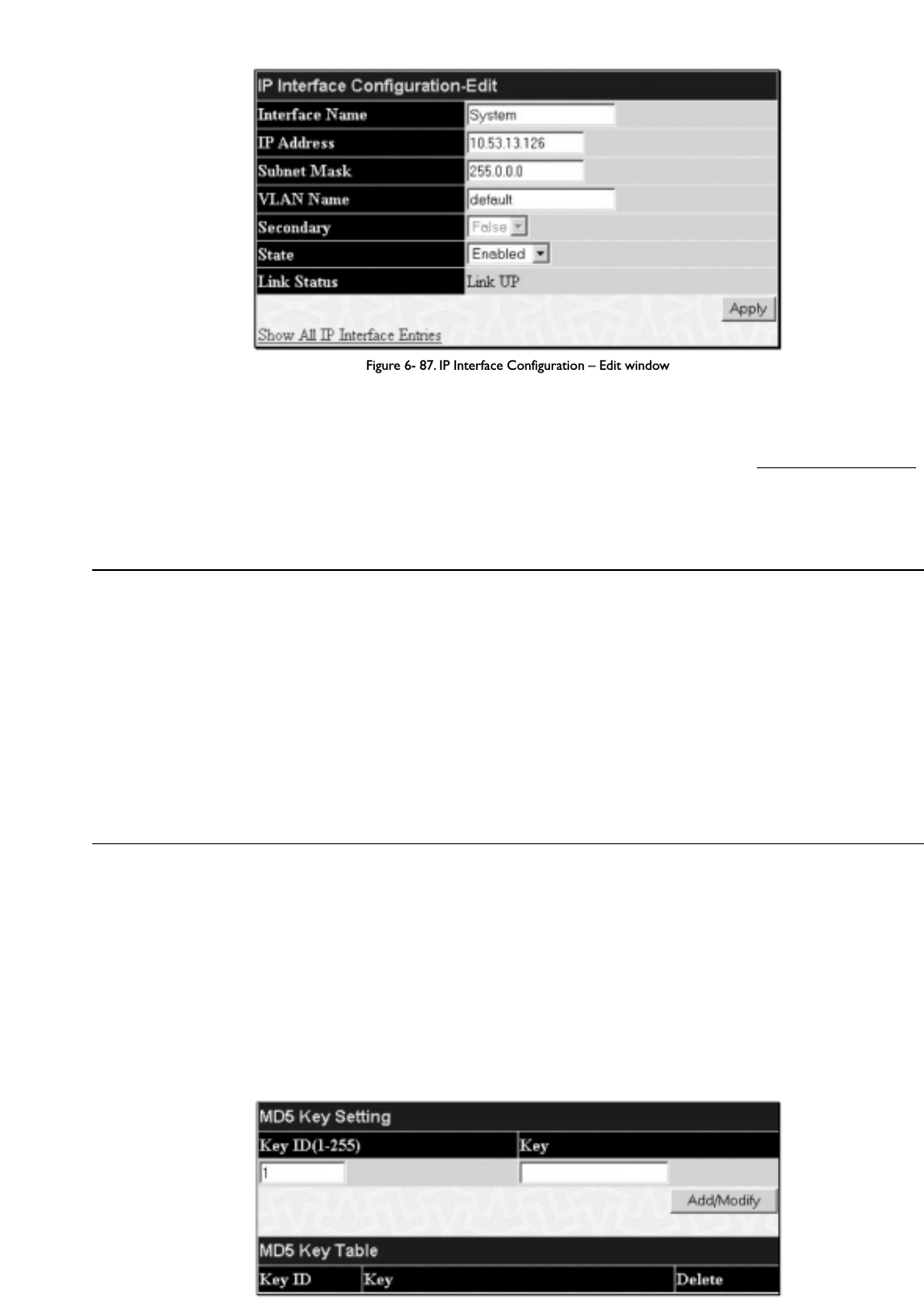
Figure 6- 87. IP Interface Configuration – Edit window
Choose a name for the interface to be added and enter it in the Interface Name field (if you are editing an IP Interface, the Interface Name will already
be in the top field as seen in the window above). Enter the interface’s IP address and subnet mask in the corresponding fields. Pull the State pull-down menu to
Enabled and click Apply to enter to make the IP interface effective.To view entries in the IP Interface Table, click the Show All IP Interface Entries
hyperlink. Use the Save Changes dialog box from the Maintenance folder to enter the changes into NV-RAM.
The following fields can be set:
Parameter Description
Interface Name This field displays the name for the IP interface.The default IP interface is named “System”.
IP Address This field allows the entry of an IP address to be assigned to this IP interface.
Subnet Mask This field allows the entry of a subnet mask to be applied to this IP interface.
VLAN Name This field allows the entry of the VLAN Name for the VLAN the IP interface belongs to.
Secondary Use the pull-down menu to set the IP interface as True or False.True will set the interface as secondary and
False will denote the interface as the primary interface of the VLAN entered above. Secondary interfaces can
only be configured if a primaryinterface is first configured.
State This field may be altered between Enabled and Disabled using the pull down menu.This entry determines
whether the interface will be active or not.
Link Status This read only field states the current status of the IP Interface on the Switch. Link Up denotes that the IP
interface is up and running on the Switch. Link Down will denote that the IP interface is not currently set
and/or enabled on the Switch.
Click Apply to implement changes made.
MD5 Key Table Configuration
The MD5 Key Table Configuration menu allows the entry of a sixteen-character Message Digest – version 5 (MD5) key which can be used to authenticate
every packet exchanged between OSPF routers. It is used as a security mechanism to limit the exchange of network topology information to the OSPF routing
domain.
MD5 Keys created here can be used in the OSPF Interface Configuration menu below.
T
o configure an MD5 Key,click the MD5 Key link to open the following dialog box:
Figure 6- 88. MD5 Key Setting and Table window
95
Allied Telesyn AT-9724TS High-Density Layer 3 Stackable Gigabit Ethernet Switch

The following fields can be set:
Parameter Description
Key ID A number from 1 to 255 used to identify the MD5 Key.
Key A alphanumeric string of between 1 and 16 case-sensitive characters used to generate the Message Digest
which is in turn, used to authenticate OSPF packets within the OSPF routing domain.
Click Apply to enter the new Key ID settings.To delete a Key ID entry, click the corresponding 8 under the Delete heading.
Route Redistribution Settings
Route redistribution allows routers on the network, which are running different routing protocols to exchange routing information.This is accomplished by
comparing the routes stored in the various routers routing tables and assigning appropriate metrics.This information is then exchanged among the various
routers according to the individual routers current routing protocol.The Switch can redistribute routing information between the OSPF and RIP routing
protocols to all routers on the network that are running OSPF or RIP. Routing information entered into the Static Routing Table on the local AT-9724TS
switch is also redistributed.
Routing information source – OSPF and the Static Route table. Routing information will be redistributed to RIP.The following table lists the allowed values for
the routing metrics and the types (or forms) of the routing information that will be redistributed.
Route Source Metric Type
OSPF 0 to 16 All
Internal
External
ExtType1
ExtType2
Inter-E1
Inter-E2
RIP 0 to 16777214 Type 1
Type 2
Static 0 to 16777214 Type 1
Type 2
Local 0 to 16777214 Type 1
Type 2
Table 6- 7. Route Redistribution Source table
Entering the Type combination – internal type_1 type_2 is functionally equivalent to all. Entering the combination type_1 type_2 is functionally equivalent to
external. Entering the combination internal external is functionally equivalent to all.
Entering the metric 0 specifies transparency.
This window will redistribute routing information between the OSPF and RIP routing protocols to all routers on the network that are running OSPF or RIP.To
access the Route Redistribution Table Configuration window,go to Configuration > Layer 3 IP Networking > Route Redistribution
Settings:
Figure 6- 89. Route Redistribution Settings and Table window
96
Allied Telesyn AT-9724TS High-Density Layer 3 Stackable Gigabit Ethernet Switch

97
Allied Telesyn AT-9724TS High-Density Layer 3 Stackable Gigabit Ethernet Switch
The following parameters may be set or viewed:
Parameter Description
Dest Protocol Allows for the selection of the protocol for the destination device. Choose between RIP and OSPF.
Src Protocol Allows for the selection of the protocol for the source device. Choose between RIP,OSPF,Static and Local.
Type Allows for the selection of one of six methods of calculating the metric value.The user may choose between
All,Internal,External,ExtType1,ExtType2,Inter-E1,Inter-E2. See the table above for available metric value types for
each source protocol.
Metric Allows the entry of an OSPF interface cost.This is analogous to a Hop Count in the RIP routing protocol.
Click Add/Modify to implement changes made.
Note: The source protocol (Src Protocol) entry and the destination protocol (Dest Protocol) entry cannot be the same.
Static/Default Route
Entries into the Switch’s forwarding table can be made using both MAC addresses and IP addresses. Static IP forwarding is accomplished by the entry of an IP
address into the Switch’s Static IP Routing Table.
Figure 6- 90. Static/Default Route Settings window
This window shows the following values:
Parameter Description
IP Address The IP address of the Static/Default Route.
Subnet Mask The corresponding Subnet Mask of the IP address entered into the table.
Gateway The corresponding Gateway of the IP address entered into the table.
Hops Represents the metric value of the IP interface entered into the table.This field may read a number between 1-
65535 for an OSPF setting, and 1-16 for a RIP setting.
Protocol Represents the protocol used for the Routing Table entry of the IP interface.This field may read OSPF, RIP,
Static or Local.
Backup State Represents the Backup state that this IP interface is configured for.This field may read Primary or Backup.
Delete Click the 8 if you would like to delete this entry from the Static/Default Route Settings table.
To enter an IP Interface into the Switch’s Static/Default Routes window, click the Add button, revealing the following window to configure.

Figure 6- 91. Static/Default Route Settings – Add window
The following fields can be set:
Parameter Description
IP Address Allows the entry of an IP address that will be a static entry into the Switch’s Routing Table.
Subnet Mask Allows the entry of a subnet mask corresponding to the IP address above.
Gateway IP Allows the entry of an IP address of a gateway for the IP address above.
Metric (1-65535) Allows the entry of a routing protocol metric representing the number of routers between the Switch and the
IP address above.
Backup State The user may choose between Primary and Backup. If the Primary Static/Default Route fails, the Backup Route
will support the entry. Please take note that the Primary and Backup entries cannot have the same Gateway.
Click Apply to implement changes made.
Route Preference Settings
Route Preference is a way for routers to select the best path when there are two or more different routes to the same destination from two different routing
protocols.The majority of routing protocols are not compatible when used in conjunction with each other.This Switch supports and may be configured for many
routing protocols, as a stand-alone switch or more importantly, in utilizing the stacking function and Single IP Management of the Switch.Therefore, the ability to
exchange route information and select the best path is essential to optimal use of the Switch and its capabilities.
The first decision the Switch will make in selecting the best path is to consult the Route Preference Settings table of the switch.This table can be viewed by
clicking Configuration > Layer 3 IP Networking > Route Preference Settings, and it holds the list of possible routing protocols currently
implemented on the Switch, along with a Preference value which determines which routing protocol will be the most dependable to route packets. Below is a
list of the default route preferences set on the Switch.
Route Type Validity Range Default Value
Local 0 – Permanently set on the switch and unconfigurable. 0
Static 1 – 999 60
OSPF Intra 1 – 999 80
OSPF Inter 1 – 999 90
RIP 1 – 999 100
OSPF ExtT1 1 – 999 110
OSPF ExtT2 1 – 999 115
Table 6- 8. Route Preference Table
As shown above, Local will always be the first choice for routing purposes and the next most reliable path is Static due to the fact that its has the next lowest
value.T
o set a higher reliability for a route, change its value to a number less than the value of a route preference that has a greater reliability value using the
New Route Preference Settings window command. For example,if the user wishes to make RIP the most reliable route, the user can change its value to
one that is less than the lowest value (Static - 60) or the user could change the other route values to more than 100.
The user should be aware of three points before configuring the route preference:
1. No two route preference values can be the same. Entering the same route preference may cause the switch to crash due to indecision by the switch.
2. If the user is not fully aware of all the features and functions of the routing protocols on the switch, a change in the default route preference value
may cause routing loops or black holes.
98
Allied Telesyn AT-9724TS High-Density Layer 3 Stackable Gigabit Ethernet Switch

3. After changing the route preference value for a specific routing protocol, that protocol needs to be restarted because the previously learned routes
have been dropped from the Switch.The Switch must learn the routes again before the new settings can take effect.
To view the Route Preference Settings window, click Configuration > Layer 3 IP Networking > Route Preference Settings:
Figure 6- 92. Current and New Route Preference Settings window
The following fields can be viewed or set:
Parameter Description
RIP (1-999) Enter a value between 1 and 999 to set the route preference for RIP.The lower the value, the higher the chance
the specified protocol will be chosen as the best path for routing packets.The default value is 100.
OSPF Intra (1-999) Enter a value between 1 and 999 to set the route preference for OSPF Intra.The lower the value,the higher the
chance the specified protocol will be chosen as the best path for routing packets.The default value is 80.
STATIC (1-999) Enter a value between 1 and 999 to set the route preference for Static.The lower the value, the higher the
chance the specified protocol will be chosen as the best path for routing packets.The default value is 60.
OSPF Inter (1-999) Enter a value between 1 and 999 to set the route preference for OSPF Inter.The lower the value, the higher the
chance the specified protocol will be chosen as the best path for routing packets.The default value is 90.
OSPF ExtT1 (1-999) Enter a value between 1 and 999 to set the route preference for OSPF ExtT1.The lower the value, the higher
the chance the specified protocol will be chosen as the best path for routing packets.The default value is 110.
OSPF ExtT2 (1-999) Enter a value between 1 and 999 to set the route preference for OSPF ExtT2.The lower the value, the higher
the chance the specified protocol will be chosen as the best path for routing packets.The default value is 115.
Click Apply to implement changes made.
99
Allied Telesyn AT-9724TS High-Density Layer 3 Stackable Gigabit Ethernet Switch

Static ARP Table
The Address Resolution Protocol (ARP) is a TCP/IP protocol that converts IP addresses into physical addresses.This table allows network managers to view, define,
modify and delete ARP information for specific devices.
Static entries can be defined in the ARP Table.When static entries are defined, a permanent entry is entered and is used to translate IP address to MAC
addresses.
To open the Static ARP Table open the Configuration folder, and then open the Layer 3 IP Networking folder and click on the Static ARP
Table link.
Figure 6- 93. Static ARP Settings window
To add a new entry, click the Add button, revealing the following screen to configure:
Figure 6- 94. Static ARP Table – Add a New Entry window
The following fields can be set:
Parameter Description
IP Address The IP address of the ARP entry.
MAC Address The MAC address of the ARP entry.
After entering the IP Address and MAC Address of the Static ARP entry, click Apply to implement the new entry.To completely clear the Static ARP
Settings, click the Clear All button.To delete an entry located in the Static ARP Settings window, click the corresponding 8under the Delete heading.
RIP
The Routing Information Protocol is a distance-vector routing protocol.There are two types of network devices running RIP – active and passive.Active devices
advertise their routes to others through RIP messages, while passive devices listen to these messages. Both active and passive routers update their routing tables
based upon RIP messages that active routers exchange. Only routers can run RIP in the active mode.
Every 30 seconds, a router running RIP broadcasts a routing update containing a set of pairs of network addresses and a distance (represented by the number of
hops or routers between the advertising router and the remote network). So, the vector is the network address and the distance is measured by the number of
routers between the local router and the remote network.
RIP measures distance by an integer count of the number of hops from one network to another.A router is one hop from a directly connected network, two
hops from a network that can be reached through a router, etc.The more routers between a source and a destination, the greater the RIP distance (or hop
count).
There are a few rules to the routing table update process that help to improve performance and stability.A router will not replace a route with a newly learned
one if the new route has the same hop count (sometimes referred to as ‘cost’). So learned routes are retained until a new route with a lower hop count is
learned.
When learned routes are entered into the routing table, a timer is started.This timer is restarted every time this route is advertised. If the route is not
advertised for a period of time (usually 180 seconds), the route is removed from the routing table.
RIP does not have an explicit method to detect routing loops. Many RIP implementations include an authorization mechanism (a password) to prevent a router
from learning erroneous routes from unauthorized routers.
100
Allied Telesyn AT-9724TS High-Density Layer 3 Stackable Gigabit Ethernet Switch

To maximize stability, the hop count RIP uses to measure distance must have a low maximum value. Infinity (that is, the network is unreachable) is defined as 16
hops. In other words, if a network is more than 16 routers from the source, the local router will consider the network unreachable.
RIP can also be slow to converge (to remove inconsistent, unreachable or looped routes from the routing table) because RIP messages propagate relatively
slowly through a network.
Slow convergence can be solved by using split horizon update, where a router does not propagate information about a route back to the interface on which it
was received.This reduces the probability of forming transient routing loops.
Hold down can be used to force a router to ignore new route updates for a period of time (usually 60 seconds) after a new route update has been received.This
allows all routers on the network to receive the message.
A router can ‘poison reverse’ a route by adding an infinite (16) hop count to a route’s advertisement.This is usually used in conjunction with triggered updates,
which force a router to send an immediate broadcast when an update of an unreachable network is received.
RIP Version 1 Message Format
There are two types of RIP messages: routing information messages and information requests. Both types use the same format.
The Command field specifies an operation according the following table:
Command Meaning
1 Request for partial or full routing information
2 Response containing network-distance pairs from sender’s routing table
3 Turn on trace mode (obsolete)
4 Turn off trace mode (obsolete)
5 Reserved for Sun Microsystem’s internal use
9 Update Request
10 Update Response
11 Update Acknowledgement
RIP Command Codes
The field Version contains the protocol version number (1 in this case), and is used by the receiver to verify which version of RIP the packet was sent.
RIP 1 Message
RIP is not limited to TCP/IP. Its address format can support up to 14 octets (when using IP, the remaining 10 octets must be zeros). Other network protocol
suites can be specified in the Family of Source Network field (IP has a value of 2).This will determine how the address field is interpreted.
RIP specifies that the IP address, 0.0.0.0, denotes a default route.
The distances, measured in router hops are entered in the Distance to Source Network, and Distance to Destination Network fields.
RIP 1 Route Interpretation
RIP was designed to be used with classed address schemes, and does not include an explicit subnet mask. An extension to version 1 does allow routers to
exchange subnetted addresses, but only if the subnet mask used by the network is the same as the subnet mask used by the address.This means the RIP version
1 cannot be used to propagate classless addresses.
Routers running RIP version 1 must send different update messages for each IP interface to which it is connected. Interfaces that use the same subnet mask as
the router’s network can contain subnetted routes, other interfaces cannot.The router will then advertise only a single route to the network.
RIP Version 2 Extensions
RIP version 2 includes an explicit subnet mask entry, so RIP version 2 can be used to propagate variable length subnet addresses or CIDR classless addresses. RIP
version 2 also adds an explicit next hop entry, which speeds convergence and helps prevent the formation of routing loops.
RIP2 Message Format
The message format used with RIP2 is an extension of the RIP1 format:
RIP version 2 also adds a 16-bit route tag that is retained and sent with router updates. It can be used to identify the origin of the route.
Because the version number in RIP2 occupies the same octet as in RIP1, both versions of the protocols can be used on a given router simultaneously without
interference.
RIP Configuration
101
Allied Telesyn AT-9724TS High-Density Layer 3 Stackable Gigabit Ethernet Switch

To setup RIP for the IP interfaces configured on the Switch, the user must enable RIP and then configure RIP settings for the individual IP interfaces.To globally
enable RIP on the Switch, open the Configuration folder to Layer 3 Networking and then open the RIP folder and click on the RIP Configuration
link to access the following screen:
Figure 6- 95. RIP Global Setting window
To enable RIP, simply use the pull down menu, select Enabled and click Apply.
Setting Up RIP
RIP settings are configured for each IP interface on the Switch. Click the RIP Interface Settings link in the RIP folder.The menu appears in table form listing
settings for IP interfaces currently on the Switch.To configure RIP settings for an individual interface, click on the hyperlinked Interface Name.To view the
next page of RIP Interface Settings, click the Next button.
Figure 6- 96. RIP Interface Settings window
Click the hyperlinked name of the interface you want to set up for RIP, which will give access to the following menu:
Figure 6- 97. RIP Interface Settings – Edit window
Refer to the table below for a description of the available parameters for RIP interface settings.
The following RIP settings can be applied to each IP interface:
102
Allied Telesyn AT-9724TS High-Density Layer 3 Stackable Gigabit Ethernet Switch

Parameter Description
Interface Name The name of the IP interface on which RIP is to be setup.This interface must be previously configured on the
Switch.
IP Address The IP address corresponding to the Interface Name showing in the field above.
TX Mode <Disabled>Toggle among Disabled,v1 Only,v1 Compatible, and v2 Only.This entry specifies which version of the RIP protocol
will be used to transmit RIP packets. Disabled prevents the transmission of RIP packets.
RX Mode <Disabled>Toggle among Disabled,v1 Only,v2 Only, and v1 or v2.This entry specifies which version of the RIP protocol will
be used to interpret received RIP packets. Disabled prevents the reception of RIP packets.
Authentication Toggle between Disabled and Enabled to specify that routers on the network should us the Password above to
authenticate router table exchanges.
Password A password to be used to authenticate communication between routers on the network.
State Toggle between Disabled and Enabled to disable or enable this RIP interface on the switch.
Interface Metric A read only field that denotes the Metric value of the current IP Interface setting.
Click Apply to implement changes made.
OSPF
The Open Shortest Path First (OSPF) routing protocol uses a link-state algorithm to determine routes to network destinations.A “link” is an interface on a
router and the “state” is a description of that interface and its relationship to neighboring routers.The state contains information such as the IP address, subnet
mask, type of network the interface is attached to, other routers attached to the network, etc.The collection of link-states is then collected in a link-state
database that is maintained by routers running OSPF.
OSPF specifies how routers will communicate to maintain their link-state database and defines several concepts about the topology of networks that use OSPF.
To limit the extent of link-state update traffic between routers, OSPF defines the concept of Area.All routers within an area share the exact same link-state
database,and a change to this database on one router triggers an update to the link-state database of all other routers in that area. Routers that have interfaces
connected to more than one area are called Border Routers and take the responsibility of distributing routing information between areas.
One area is defined as Area 0 or the Backbone.This area is central to the rest of the network in that all other areas have a connection (through a router) to the
backbone.Only routers have connections to the backbone and OSPF is structured such that routing information changes in other areas will be introduced into
the backbone,and then propagated to the rest of the network.
When constructing a network to use OSPF, it is generally advisable to begin with the backbone (area 0) and work outward.
Link-State Algorithm
An OSPF router uses a link-state algorithm to build a shortest path tree to all destinations known to the router.The following is a simplified description of the
algorithm’s steps:
•When OSPF is started, or when a change in the routing information changes, the router generates a link-state advertisement.This advertisement is a
specially formatted packet that contains information about all the link-states on the router.
• This link-state advertisement is flooded to all router in the area. Each router that receives the link-state advertisement will store the advertisement
and then forward a copy to other routers.
• When the link-state database of each router is updated, the individual routers will calculate a Shortest Path Tree to all destinations - with the
individual router as the root.The IP routing table will then be made up of the destination address, associated cost, and the address of the next hop to
reach each destination.
•Once the link-state databases are updated, Shortest Path Trees calculated, and the IP routing tables written - if there are no subsequent changes in the
OSPF network (such as a network link going down) there is very little OSPF traffic.
Shortest Path Algorithm
The Shortest Path to a destination is calculated using the Dijkstra algorithm. Each router is places at the root of a tree and then calculates the shortest path to
each destination based on the cumulative cost to reach that destination over multiple possible routes. Each router will then have its own Shortest Path Tree
(from the perspective of its location in the network area) even though every router in the area will have and use the exact same link-state database.
The following sections describe the information used to build the Shortest Path Tree.
OSPF Cost
Each OSPF interface has an associated cost (also called “metric”) that is representative of the overhead required to send packets over that interface.This cost is
inversely proportional to the bandwidth of the interface (i.e. a higher bandwidth interface has a lower cost).There is then a higher cost (and longer time delays)
in sending packets over a 56 Kbps dial-up connection than over a 10Mbps Ethernet connection.The formula used to calculate the OSPF cost is as follows:
Cost = 100,000,000 / bandwidth in bps
As an example, the cost of a 10Mbps Ethernet line will be 10 and the cost to cross a 1.544Mbps T1 line will be 64.
103
Allied Telesyn AT-9724TS High-Density Layer 3 Stackable Gigabit Ethernet Switch
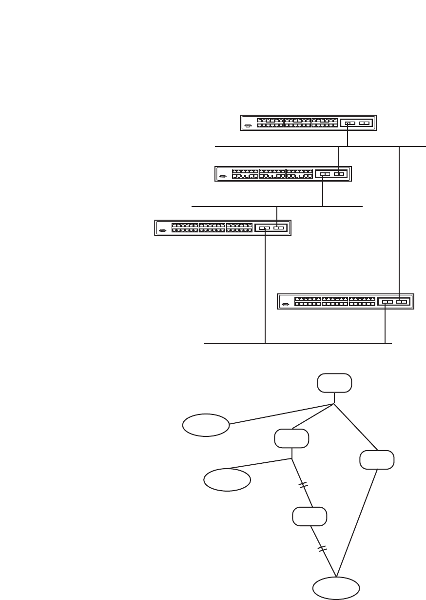
Shortest Path Tree
To build Router A’s shortest path tree for the network diagrammed below, Router A is put at the root of the tree and the smallest cost link to each destination
network is calculated.
Figure 6- 98. Constructing a Shortest Path Tree
The diagram above shows the network from the viewpoint of Router A. Router A can reach 192.213.11.0 through Router B with a cost of 10+5=15. Router A
can reach 222.211.10.0 through Router C with a cost of 10+10=20. Router A can also reach 222.211.10.0 through Router B and Router D with a cost of
10+5+10=25, but the cost is higher than the route through Router C.This higher-cost route will not be included in the Router A’s shortest path tree.The
resulting tree will look like this:
104
Allied Telesyn AT-9724TS High-Density Layer 3 Stackable Gigabit Ethernet Switch
135 7911
246 8 10 12
13 15
14 16
17 19 21 23
18 20 22 24
25 27
26 28
29 31 33 35
30 32 34 36
1357
911
24681012
13 15
14 16
17 19 21 23
18 20 22 24
25 27
26 28
29 31 33 35
30 32 34 36
1357
911
24 6 8 10 12
13 15
14 16
17 19 21 23
18 20 22 24
25 27
26 28
29 31 33 35
30 32 34 36
1357
911
24 6 8 10 12
13 15
14 16
17 19 21 23
18 20 22 24
25 27
26 28
29 31 33 35
30 32 34 36
Router A
Router B
Router C
Router D
10
8
5
5
10
10
10
128.213.0.0
192.128.11.0
222.211.10.0
Router A
Router B
Router C
Router D
128.213.0.0
192.213.11.0
222.211.10.0
0
10
10
10
5
5
10

Figure 6- 99. Constructing a Shortest Path Tree – Completed
Note that this shortest path tree is only from the viewpoint of Router A.The cost of the link from Router B to Router A, for instance is not important to
constructing Router A’s shortest path tree, but is very important when Router B is constructing its shortest path tree.
Note also that directly connected networks are reached at a cost of 0, while other networks are reached at the cost calculated in the shortest path tree.
Router A can now build its routing table using the network addresses and costs calculated in building the above shortest path tree.
Areas and Border Routers
OSPF link-state updates are forwarded to other routers by flooding to all routers on the network. OSPF uses the concept of areas to define where on the
network routers that need to receive particular link-state updates are located.This helps ensure that routing updates are not flooded throughout the entire
network and to reduce the amount of bandwidth consumed by updating the various router’s routing tables.
Areas establish boundaries beyond which link-state updates do not need to be flooded. So the exchange of link-state updates and the calculation of the shortest
path tree are limited to the area that the router is connected to.
Routers that have connections to more than one area are called Border Routers (BR).The Border Routers have the responsibility of distributing necessary
routing information and changes between areas.
Areas are specific to the router interface.A router that has all of its interfaces in the same area is called an Internal Router.A router that has interfaces in
multiple areas is called a Border Router. Routers that act as gateways to other networks (possibly using other routing protocols) are called Autonomous System
Border Routers (ASBRs).
Link-State Packets
There are a number of different types of link-state packets, four of which are illustrated below:
•Router Link-State Updates – These describe a router’s links to destinations within an area.
• Summary Link-State Updates – Issued by Border Routers and describe links to networks outside the area but within the Autonomous System (AS).
• Network Link-State Updates – Issued by multi-access areas that have more than one attached router. One router is elected as the Designated Router
(DR) and this router issues the network link-state updates describing every router on the segment.
• External Link-State Updates – Issued by an Autonomous System Border Router and describes routes to destinations outside the AS or a default route
to the outside AS.
The format of these link-state updates is described in more detail below.
Router link-state updates are flooded to all routers in the current area.These updates describe the destinations reachable through all of the router’s interfaces.
Summary link-state updates are generated by Border Routers to distribute routing information about other networks within the AS. Normally, all Summary link-
state updates are forwarded to the backbone (area 0) and are then forwarded to all other areas in the network. Border Routers also have the responsibility of
distributing routing information from the Autonomous System Border Router in order for routers in the network to get and maintain routes to other
Autonomous Systems.
Network link-state updates are generated by a router elected as the Designated Router on a multi-access segment (with more than one attached router).These
updates describe all of the routers on the segment and their network connections.
External link-state updates carry routing information to networks outside the Autonomous System.The Autonomous System Border Router is responsible for
generating and distributing these updates.
105
Allied Telesyn AT-9724TS High-Density Layer 3 Stackable Gigabit Ethernet Switch
Router A
Router B
Router C
128.213.0.0
192.213.11.0
222.211.10.0
0
10
10
5
10

OSPF Authentication
OSPF packets can be authenticated as coming from trusted routers by the use of predefined passwords.The default for routers is to use not authentication.
There are two other authentication methods – simple password authentication (key) and Message Digest authentication (MD-5).
Message Digest Authentication (MD-5)
MD-5 authentication is a cryptographic method.A key and a key-ID are configured on each router.The router then uses an algorithm to generate a mathematical
“message digest” that is derived from the OSPF packet, the key and the key-ID.This message digest (a number) is then appended to the packet.The key is not
exchanged over the wire and a non-decreasing sequence number is included to prevent replay attacks.
Simple Password Authentication
A password (or key) can be configured on a per-area basis. Routers in the same area that participate in the routing domain must be configured with the same key.
This method is possibly vulnerable to passive attacks where a link analyzer is used to obtain the password.
Backbone and Area 0
OSPF limits the number of link-state updates required between routers by defining areas within which a given router operates.When more than one area is
configured, one area is designated as area 0 – also called the backbone.
The backbone is at the center of all other areas – all areas of the network have a physical (or virtual) connection to the backbone through a router. OSPF allows
routing information to be distributed by forwarding it into area 0, from which the information can be forwarded to all other areas (and all other routers) on the
network.
In situations where an area is required, but is not possible to provide a physical connection to the backbone, a virtual link can be configured.
Virtual Links
Virtual links accomplish two purposes:
• Linking an area that does not have a physical connection to the backbone.
• Patching the backbone in case there is a discontinuity in area 0.
Areas Not Physically Connected to Area 0
All areas of an OSPF network should have a physical connection to the backbone, but is some cases it is not possible to physically connect a remote area to the
backbone. In these cases, a virtual link is configured to connect the remote area to the backbone.A virtual path is a logical path between two border routers that
have a common area, with one border router connected to the backbone.
Partitioning the Backbone
OSPF also allows virtual links to be configured to connect the parts of the backbone that are discontinuous.This is the equivalent to linking different area 0s
together using a logical path between each area 0.Virtual links can also be added for redundancy to protect against a router failure.A virtual link is configured
between two border routers that both have a connection to their respective area 0s.
Neighbors
Routers that are connected to the same area or segment become neighbors in that area. Neighbors are elected via the Hello protocol. IP multicast is used to
send out Hello packets to other routers on the segment. Routers become neighbors when they see themselves listed in a Hello packet sent by another router
on the same segment. In this way,two-way communication is guaranteed to be possible between any two neighbor routers.
Any two routers must meet the following conditions before the become neighbors:
•Area ID –T
wo routers having a common segment – their interfaces have to belong to the same area on that segment. Of course, the interfaces
should belong to the same subnet and have the same subnet mask.
•Authentication – OSPF allows for the configuration of a password for a specific area.Two routers on the same segment and belonging to the
same area must also have the same OSPF password before they can become neighbors.
•Hello and Dead Intervals – The Hello interval specifies the length of time, in seconds, between the hello packets that a router sends on an OSPF
interface.The dead interval is the number of seconds that a router’s Hello packets have not been seen before its neighbors declare the OSPF router
down. OSPF routers exchange Hello packets on each segment in order to acknowledge each other’s existence on a segment and to elect a
Designated Router on multi-access segments. OSPF requires these intervals to be exactly the same between any two neighbors. If any of these
intervals are different, these routers will not become neighbors on a particular segment.
•Stub Area Flag – Any two routers also have to have the same stub area flag in their Hello packets in order to become neighbors.
106
Allied Telesyn AT-9724TS High-Density Layer 3 Stackable Gigabit Ethernet Switch

Adjacencies
Adjacent routers go beyond the simple Hello exchange and participate in the link-state database exchange process. OSPF elects one router as the Designated
Router (DR) and a second router as the Backup Designated Router (BDR) on each multi-access segment (the BDR is a backup in case of a DR failure).All other
routers on the segment will then contact the DR for link-state database updates and exchanges.This limits the bandwidth required for link-state database
updates.
Designated Router Election
The election of the DR and BDR is accomplished using the Hello protocol.The router with the highest OSPF priority on a given multi-access segment will
become the DR for that segment. In case of a tie, the router with the highest Router ID wins.The default OSPF priority is 1.A priority of zero indicates a router
that cannot be elected as the DR.
Building Adjacency
Two routers undergo a multi-step process in building the adjacency relationship.The following is a simplified description of the steps required:
•Down – No information has been received from any router on the segment.
•Attempt – On non-broadcast multi-access networks (such as Frame Relay or X.25), this state indicates that no recent information has been
received from the neighbor.An effort should be made to contact the neighbor by sending Hello packets at the reduced rate set by the Poll Interval.
•Init – The interface has detected a Hello packet coming from a neighbor but bi-directional communication has not yet been established.
•Two-way – Bi-directional communication with a neighbor has been established.The router has seen its address in the Hello packets coming from a
neighbor.At the end of this stage the DR and BDR election would have been done.At the end of the Two-way stage, routers will decide whether to
proceed in building an adjacency or not.The decision is based on whether one of the routers is a DR or a BDR or the link is a point-to-point or
virtual link.
•Exstart – (Exchange Start) Routers establish the initial sequence number that is going to be used in the information exchange packets.The sequence
number insures that routers always get the most recent information. One router will become the primary and the other will become secondary.The
primary router will poll the secondary for information.
•Exchange – Routers will describe their entire link-state database by sending database description packets.
•Loading – The routers are finalizing the information exchange. Routers have link-state request list and a link-state retransmission list.Any
information that looks incomplete or outdated will be put on the request list.Any update that is sent will be put on the retransmission list until it gets
acknowledged.
•Full – The adjacency is now complete.The neighboring routers are fully adjacent.Adjacent routers will have the same link-state database.
Adjacencies on Point-to-Point Interfaces
OSPF Routers that are linked using point-to-point interfaces (such as serial links) will always form adjacencies.The concepts of DR and BDR are unnecessary.
OSPF Packet Formats
All OSPF packet types begin with a standard 24-byte header and there are five packet types.The header is described first, and each packet type is described in a
subsequent section.
All OSPF packets (except for Hello packets) forward link-state advertisements. Link-State Update packets, for example, flood advertisements throughout the
OSPF routing domain.
•OSPF packet header
• Hello packet
• Database Description packet
• Link-State Request packet
• Link-State Update packet
• Link-State Acknowledgment packet
OSPF Packet Header
Every OSPF packet is preceded by a common 24-byte header.This header contains the information necessary for a receiving router to determine if the packet
should be accepted for further processing.
The format of the OSPP packet header is shown below:
107
Allied Telesyn AT-9724TS High-Density Layer 3 Stackable Gigabit Ethernet Switch

Figure 6- 101. Hello Packet
Field Description
Network Mask The network mask associated with this interface.
Options The optional capabilities supported by the router.
Hello Interval The number of seconds between this router’s Hello packets.
Router Priority This router’s Router Priority.The Router Priority is used in the election of the DR and BDR. If this field is set
to 0, the router is ineligible become the DR or the BDR.
Router Dead Interval The number of seconds that must pass before declaring a silent router as down.
Designated Router The identity of the DR for this network, in the view of the advertising router.The DR is identified here by its IP
interface address on the network.
Backup Designated Router The identity of the Backup Designated Router (BDR) for this network.The BDR is identified here by its IP
interface address on the network.This field is set to 0.0.0.0 if there is no BDR.
Neighbor The Router IDs of each router from whom valid Hello packets have been seen within the Router Dead Interval
on the network.
Database Description Packet
Database Description packets are OSPF packet type 2.These packets are exchanged when an adjacency is being initialized.They describe the contents of the
topological database.Multiple packets may be used to describe the database.For this purpose a poll-response procedure is used. One of the routers is designated
to be master, the other a slave.The master seconds Database Description packets (polls) that are acknowledged by Database Description packets sent by the
slave (responses).The responses are linked to the polls via the packets’ DD sequence numbers.
109
Allied Telesyn AT-9724TS High-Density Layer 3 Stackable Gigabit Ethernet Switch
Version No. 1Packet Length
Octets
0123
OSPF Hello Packet
Router ID
Area ID
Checksum Authentication Type
Authentication
Authentication
Network Mask
Options Router Priority
Hello Interval
Router Dead Interval
Designated Router
Backup Designated Router
Neighbour
4

Figure 6- 102. Database Description Packet
Field Description
Options The optional capabilities supported by the router.
I – bit The Initial bit.When set to 1, this packet is the first in the sequence of Database Description packets.
M – bit The More bit.When set to 1, this indicates that more Database Description packets will follow.
MS – bit The Master Slave bit.When set to 1, this indicates that the router is the master during the Database Exchange
process.A zero indicates the opposite.
DD Sequence Number User to sequence the collection of Database Description Packets.The initial value (indicated by the Initial bit
being set) should be unique.The DD sequence number then increments until the complete database
description has been sent.
The rest of the packet consists of a list of the topological database’s pieces. Each link state advertisement in the database is described by its link state
advertisement header.
Link-State Request Packet
Link-State Request packets are OSPF packet type 3.After exchanging Database Description packets with a neighboring router, a router may find that parts of its
topological database are out of date.The Link-State Request packet is used to request the pieces of the neighbor’s database that are more up to date. Multiple
Link-State Request packets may need to be used.The sending of Link-State Request packets is the last step in bringing up an adjacency.
A router that sends a Link-State Request packet has in mind the precise instance of the database pieces it is requesting, defined by LS sequence number, LS
checksum, and LS age, although these fields are not specified in the Link-State Request packet itself.The router may receive even more recent instances in
response.
The format of the Link-State Request packet is shown below:
110
Allied Telesyn AT-9724TS High-Density Layer 3 Stackable Gigabit Ethernet Switch
Version No. 2Packet Length
Octets
01 23
OSPF Database Description Packet
Router ID
Area ID
Checksum Authentication Type
Authentication
Authentication
DD Sequence No.
Link-State Advertisement Header
Reserved I M MS Reserved Options
4

Figure 6- 103. Link-State Request Packet
Each advertisement requested is specified by its Link-State Type, Link-State ID, and Advertising Router.This uniquely identifies the advertisement, but not its
instance. Link-State Request packets are understood to be requests for the most recent instance.
Link-State Update Packet
Link-State Update packets are OSPF packet type 4.These packets implement the flooding of link-state advertisements. Each Link-State Update packet carries a
collection of link-state advertisements one hop further from its origin. Several link-state advertisements may be included in a single packet.
Link-State Update packets are multicast on those physical networks that support multicast/broadcast. In order to make the flooding procedure reliable, flooded
advertisements are acknowledged in Link-State Acknowledgment packets. If retransmission of certain advertisements is necessary, the retransmitted
advertisements are always carried by unicast Link-State Update packets.
The format of the Link-State Update packet is shown below:
Figure 6- 104. Link-State Update Packet
The body of the Link-State Update packet consists of a list of link-state advertisements. Each advertisement begins with a common 20-byte header, the link-state
advertisement header. Otherwise, the format of each of the five types of link-state advertisements is different.
111
Allied Telesyn AT-9724TS High-Density Layer 3 Stackable Gigabit Ethernet Switch
Octets
OSPF Link-State Request Packet
Router ID
Area ID
Checksum Authentication Type
Authentication
Authentication
Link-State ID
Advertising Router
Link-State Type
Version No. 3Packet Length
01 23 4
Octets
OSPF Link-State Update Packet
Router ID
Area ID
Checksum Authentication Type
Authentication
Authentication
Link-State Advertisements
Number of Advertisements
Version No. 4Packet Length
01 23 4

Link State Advertisement Header
All link state advertisements begin with a common 20-byte header.This header contains enough information to uniquely identify the advertisements (Link State
Type, Link State ID, and Advertising Router). Multiple instances of the link state advertisement may exist in the routing domain at the same time. It is then
necessary to determine which instance is more recent.This is accomplished by examining the link state age, link state sequence number and link state checksum
fields that are also contained in the link state advertisement header.
The format of the Link State Advertisement Header is shown below:
Figure 6- 106. Link State Advertisement Header
Field Description
Link State Age The time is seconds since the link state advertisement was originated.
Options The optional capabilities supported by the described portion of the routing domain.
Link State Type The type of the link state advertisement. Each link state type has a separate advertisement format.
The link state type are as follows: Router Links, Network Links, Summary Link (IP Network), Summary Link
(ASBR),AS External Link.
Link State ID This field identifies the portion of the internet environment that is being described by the advertisement.The
contents of this field depend on the advertisement’s Link State Type.
Advertising Router The Router ID of the router that originated the Link State Advertisement. For example, in network links
advertisements this field is set to the Router ID of the network’s Designated Router.
Link State Sequence Number Detects old or duplicate link state advertisements. Successive instances of a link state advertisement are given
successive Link State Sequence numbers.
Link State Checksum The Fletcher checksum of the complete contents of the link state advertisement, including the link state
advertisement header by accepting the Link State Age field.
Length The length in bytes of the link state advertisement.This includes the 20-byte link state advertisement header.
Router Links Advertisements
Router links advertisements are type 1 link state advertisements. Each router in an area originates a routers links advertisement.The advertisement describes the
state and cost of the router’s links to the area.All of the router’s links to the area must be described in a single router links advertisement.
The format of the Router Links Advertisement is shown below:
113
Allied Telesyn AT-9724TS High-Density Layer 3 Stackable Gigabit Ethernet Switch
Octets
OSPF Link-State Advertisement Header
Link-State ID
Advertising Router
Link-State Checksum Length
Link-State Sequence Number
Link State Age Options Link-State Type
01 23 4

Figure 6- 107. Routers Links Advertisements
In router links advertisements, the Link State ID field is set to the router’s OSPF Router ID.The T-bit is set in the advertisement’s Option field if and only if the
router is able to calculate a separate set of routes for each IP Type of Service (TOS). Router links advertisements are flooded throughout a single area only.
Field Description
V – bit When set, the router is an endpoint of an active virtual link that is using the described area as a Transit area (V
is for Virtual link endpoint).
E – bit When set, the router is an Autonomous System (AS) boundary router (E is for External).
B – bit When set, the router is an area border router (B is for Border).
Number of LinksThe number of router links described by this advertisement.This must be the total collection of router links to
the area.
The following fields are used to describe each router link. Each router link is typed.The Type field indicates the kind of link being described. It may be a link to a
transit network, to another router or to a stub network.The values of all the other fields describing a router link depend on the link’s Type. For example, each
link has an associated 32-bit data field. For links to stub networks this field specifies the network’s IP address mask. For other link types the Link Data specifies
the router’s associated IP interface address.
Field Description
Type A quick classification of the router link. One of the following:Type Description Point-to-point connection to
another router.Connection to a transit network. Connection to a stub network.Virtual link.
Link ID Identifies the object that this router link connects to.Value depends on the link’s Type.When connecting to an
object that also originates a link state advertisement (i.e. another router or a transit network) the Link ID is
equal to the neighboring advertisement’s Link State ID.This provides the key for looking up an advertisement in
the link state database.Type Link ID Neighboring router’s Router ID. IP address of Designated Router. IP
network/subnet number. Neighboring router’s Router ID.
Link Data Contents again depend on the link’s Type field. For connections to stub networks, it specifies the network’s IP
address mask. For unnumbered point-to-point connection, it specifies the interface’s MIB-II ifIndex value. For
other link types it specifies the router’s associated IP interface address.This latter piece of information is
needed during the routing table build process, when calculating the IP address of the next hop.
No. of TOS The number of different Type of Service (TOS) metrics given for this link, not counting the required metric for
TOS 0. If no additional TOS metrics are given, this field should be set to 0.
TOS 0 Metric The cost of using this router link for TOS 0.
114
Allied Telesyn AT-9724TS High-Density Layer 3 Stackable Gigabit Ethernet Switch
Octets
Router Links Advertisements
Link-State ID
Advertising Router
Link-State Checksum Length
Link-State Sequence Number
01 23 4
Link-State Age Options Link-State Type
Reserved V E B Reserved Number of Links
Link-ID
Link Data
Ty p eNo. of TOS TOS 0 Metric
TOS 0 Metric
...
TOS 0 Metric
...
Link-ID
Link Data

OSPF Virtual Interface Settings
Click the OSPF Virtual Interface Settings link to view the current OSPF Virtual Interface Settings.There are not virtual interface settings
configured by default, so the first time this table is viewed there will be not interfaces listed.To add a new OSPF virtual interface configuration set to the table,
click the Add button.A new menu appears (see below).To change an existing configuration, click on the hyperlinked Transit Area ID for the set you want to
change.The menu to modify an existing set is the same as the menu used to add a new one.To eliminate an existing configuration, click the 8in the Delete
column.
Figure 6- 116. OSPF Virtual Interface Settings window
The status of the virtual interface appears (Up or Down) in the Status column.
Figure 6- 117. OSPF Virtual Link Setting – Add
Configure the following parameters if you are adding or changing an OSPF Virtual Interface:
Parameter Description
Transit Area ID Allows the entry of an OSPF Area ID – previously defined on the Switch – that allows a remote area to
communicate with the backbone (area 0).A Transit Area cannot be a Stub Area or a Backbone Area.
Neighbor Router The OSPF router ID for the remote router.This is a 32-bit number in the form of an IP address
(xxx.xxx.xxx.xxx) that uniquely identifies the remote area’s Area Border Router.
Hello Interval (1-65535) Specify the interval between the transmission of OSPF Hello packets, in seconds. Enter a value between 1 and
65535 seconds.The Hello Interval, Dead Interval,Authorization Type, and Authorization Key should have
identical settings for all routers on the same network.
Dead Interval (1-65535) Specify the length of time between (receiving) Hello packets from a neighbor router before the selected area
declares that router down.Again, all routers on the network should use the same setting.
Auth Type If using authorization for OSPF routers, select the type being used. MD5 key authorization must be set up in
the MD5 Key Settings menu.
Password/Auth. Key ID Enter a case-sensitive password for simple authorization or enter the MD5 key you set in the MD5 Key settings
menu.
Transmit Delay The number of seconds required to transmit a link state update over this virtual link.Transit delay takes into
account transmission and propagation delays.This field is fixed at 1 second.
RetransInterval The number of seconds between link state advertisement retransmissions for adjacencies belonging to this
virtual link.This field is fixed at 5 seconds.
Click Apply to implement changes made.
Note: For OSPF to function properly some settings should be identical on all participating OSPF devices.These settings include the Hello Interval
and Dead Interval. For networks using authorization for OSPF devices, the Authorization Type and Password or Key used must likewise be identical.
120
Allied Telesyn AT-9724TS High-Density Layer 3 Stackable Gigabit Ethernet Switch

Mapping Domain Names to Addresses
Name-to-address translation is performed by a program called a Name server.The client program is called a Name resolver.A Name resolver may need to
contact several Name servers to translate a name to an address.
The Domain Name System (DNS) servers are organized in a somewhat hierarchical fashion.A single server often holds names for a single network, which is
connected to a root DNS server – usually maintained by an ISP.
Domain Name Resolution
The domain name system can be used by contacting the name servers one at a time, or by asking the domain name system to do the complete name translation.
The client makes a query containing the name, the type of answer required, and a code specifying whether the domain name system should do the entire name
translation, or simply return the address of the next DNS server if the server receiving the query cannot resolve the name.
When a DNS server receives a query, it checks to see if the name is in its sub domain. If it is, the server translates the name and appends the answer to the
query, and sends it back to the client. If the DNS server cannot translate the name, it determines what type of name resolution the client requested.A complete
translation is called recursive resolution and requires the server to contact other DNS servers until the name is resolved. Iterative resolution specifies that if the
DNS server cannot supply an answer, it returns the address of the next DNS server the client should contact.
Each client must be able to contact at least one DNS server, and each DNS server must be able to contact at least one root server.
The address of the machine that supplies domain name service is often supplied by a DHCP or BOOTP server, or can be entered manually and configured into
the operating system at startup.
Configuring DNS Relay Information
To configure the DNS function on the Switch, open the Configuration folder and click the DNS Relay folder. In this folder, click the DNS Relay
Information link to open the following window.
Figure 6- 124. DNS Global Settings window
The following fields can be set:
Parameter Description
DNS Relay Status This field can be toggled between Disabled and Enabled using the pull-down menu, and is used to enable or
disable the DNS Relay service on the Switch.
Primary Name Server Allows the entry of the IP address of a primary domain name server (DNS).
Secondary Name Server Allows the entry of the IP address of a secondary domain name server (DNS).
DNSR Cache Status This can be toggled between Disabled and Enabled.This determines if a DNS cache will be enabled on the
Switch.
DNS Static Table Status This field can be toggled using the pull-down menu between Disabled and Enabled.This determines if the static
DNS table will be used or not.
DNS Relay Static Settings
T
o view the DNS Relay Static Settings,open the DNS Relay folder in the Configuration folder and click the DNS Relay Static Settings link,
which will open the following window.
124
Allied Telesyn AT-9724TS High-Density Layer 3 Stackable Gigabit Ethernet Switch

Figure 6- 125. DNS Relay Static Settings and Table window
To add an entry into the DNS Relay Static Table, simply enter a Domain Name with its corresponding IP address and click Add.A successful entry will be
presented in the table below, as shown in the example above.To erase an entry from the table, click the corresponding 8of the entry you wish to delete.
VRRP
VRRP or Virtual Routing Redundancy Protocol is a function on the Switch that dynamically assigns responsibility for a virtual router to one of the VRRP routers on a
LAN.The VRRP router that controls the IP address associated with a virtual router is called the Master, and will forward packets sent to this IP address.This will
allow any Virtual Router IP address on the LAN to be used as the default first hop router by end hosts. Utilizing VRRP, the administrator can achieve a higher
available default path cost without needing to configure every end host for dynamic routing or routing discovery protocols.
Statically configured default routes on the LAN are prone to a single point of failure.VRRP is designed to eliminate these failures by setting an election protocol
that will assign a responsibility for a virtual router to one of the VRRP routers on the LAN.When a virtual router fails, the election protocol will select a virtual
router with the highest priority to be the Master router on the LAN.This retains the link and the connection is kept alive, regardless of the point of failure.
To configure VRRP for virtual routers on the Switch, an IP interface must be present on the system and it must be a part of a VLAN.VRRP IP interfaces may be
assigned to every VLAN, and therefore IP interface, on the Switch.VRRP routers within the same VRRP group must be consistent in configuration settings for this
protocol to function optimally.
VRRP Configuration
To enable VRRP globally on the Switch, click Configuration > Layer 3 IP Networking > VRRP > VRRP Global Settings:
Figure 6- 126.VRRP Global Settings window
The following fields can be set:
Parameter Description
Global VRRP Use the pull-down menu to enable or disable VRRP globally on the Switch.The default is Disabled.
Non-owner response PING Enabling this parameter will allow the virtual IP address to be pinged from other host end nodes to verify
connectivity.This will only enable the ping connectivity check function.This command is Disabled by default.
Click Apply to implement changes made.
125
Allied Telesyn AT-9724TS High-Density Layer 3 Stackable Gigabit Ethernet Switch

VRRP Interface Settings
The following window will allow the user to view the parameters for the VRRP function on the Switch.To view this window, click Configuration > Layer 3
IP Networking > VRRP > VRRP Configuration:
Figure 6- 127.VRRP Configuration window
The following fields are displayed in the window above:
Parameter Description
Interface Name An IP interface name that has been enabled for VRRP.This entry must have been previously set in the IP
Interfaces table.
Authentication type Displays the type of authentication used to compare VRRP packets received by a virtual router. Possible
authentication types include
No authentication – No authentication has been selected to compare VRRP packets received by a virtual router.
Simple Text Password – A Simple password has been selected to compare VRRP packets received by a virtual
router, for authentication.
IP Authentication Header – An MD5 message digest algorithm has been selected to compare VRRP packets
received by a virtual router, for authentication.
VRID Displays the virtual router ID set by the user.This will uniquely identify the VRRP Interface on the network.
Display Click the View button to display the settings for this particular VRRP entry.
Delete Click the 8 to delete this VRRP entry.
Click the Add button to display the following window to configure a VRRP interface.
Figure 6- 128.VRRP Interface Settings – Add window
Or, the user may click the hyperlinked Interface Name to view the same window:
The following parameters may be set to configure an existing or new VRRP interface.
126
Allied Telesyn AT-9724TS High-Density Layer 3 Stackable Gigabit Ethernet Switch

Parameter Description
Interface Name Enter the name of a previously configured IP interface to create a VRRP entry for.This IP interface must be
assigned to a VLAN on the Switch.
VRID (1-255) Enter a value between 1and 255 to uniquely identify this VRRP group on the Switch.All routers participating in
this group must be assigned the same VRID value.This value MUST be different from other VRRP groups set on
the Switch.
IP Address Enter the IP address that will be assigned to the VRRP router.This IP address is also the default gateway that
will be statically assigned to end hosts and must be set for all routers that participate in this group.
Admin. State Used to enable (Up) and disable (Down) the VRRP IP interface on the Switch.
Priority (1-254) Enter a value between 1 and 254 to indicate the router priority.The VRRP Priority value may determine if a
higher priority VRRP router overrides a lower priority VRRP router.A higher priority will increase the
probability that this router will become the Master router of the group.A lower priority will increase the
probability that this router will become the backup router.VRRP routers that are assigned the same priority
value will elect the highest physical IP address as the Master router.The default value is 100. (The value of 255 is
reserved for the router that owns the IP address associated with the virtual router and is therefore set
automatically.)
Advertisement Interval (1-255) Enter a time interval value, in seconds, for sending VRRP message packets.This value must be consistent with all
participating routers.The default is 1 second.
Preempt Mode This entry will determine the behavior of backup routers within the VRRP group by controlling whether a
higher priority backup router will preempt a lower priority Master router.A True entry, along with having the
backup router’s priority set higher than the masters priority, will set the backup router as the Master router.A
False entry will disable the backup router from becoming the Master router.This setting must be consistent
with all routers participating within the same VRRP group.The default setting is True.
Critical IP Address Enter the IP address of the physical device that will provide the most direct route to the Internet or other
critical network connections from this virtual router.This must be a real IP address of a real device on the
network. If the connection from the virtual router to this IP address fails, the virtual router will automatically
disabled.A new Master will be elected from the backup routers participating in the VRRP group. Different
critical IP addresses may be assigned to different routers participating in the VRRP group, and can therefore
define multiple routes to the Internet or other critical network connections.
Checking Critical IP Use the pull-down menu to enable or disable the Critical IP address entered above.
Auth. Type Specifies the type of authentication used.The Auth.Type must be consistent with all routers participating within
the VRRP group.The choices are:
None – Selecting this parameter indicates that VRRP protocol exchanges will not be authenticated.
Simple – Selecting this parameter will require the user to set a simple password in the Auth. Data field for
comparing VRRP message packets received by a router. If the two passwords are not exactly the same, the
packet will be dropped.
IP – Selecting this parameter will require the user to set a MD5 message digest for authentication in comparing
VRRP messages received by the router. If the two values are inconsistent, the packet will be dropped.
Auth. Data This field is only valid if the user selects Simple or IP in the Auth.Type field. Simple will require the user to
enter an alphanumeric string of no more than 8 characters to identify VRRP packets received by a router. IP will
require the user to enter a MD5 message digest for authentication in comparing VRRP messages received by
the router.This entry must be consistent with all routers participating in the same IP interface.
Click Apply to implement changes made.
To view the settings for a particular VRRP setting, click the corresponding View in the VRRP Interface Table of the entry, which will display the following:
127
Allied Telesyn AT-9724TS High-Density Layer 3 Stackable Gigabit Ethernet Switch

DVMRP Interface Configuration
The Distance Vector Multicast Routing Protocol (DVMRP) is a hop-based method of building multicast delivery trees from multicast sources to all nodes of a
network. Because the delivery trees are ‘pruned’ and ‘shortest path’, DVMRP is relatively efficient. Because multicast group membership information is forwarded
by a distance-vector algorithm, propagation is slow. DVMRP is optimized for high delay (high latency) relatively low bandwidth networks, and can be considered as
a ‘best-effort’ multicasting protocol.
DVMRP resembles the Routing Information Protocol (RIP), but is extended for multicast delivery. DVMRP builds a routing table to calculate ‘shortest paths’ back
to the source of a multicast message, but defines a ‘route cost’ (similar to the hop count in RIP) as a relative number that represents the real cost of using this
route in the construction of a multicast delivery tree to be ‘pruned’ – once the delivery tree has been established.
When a sender initiates a multicast, DVMRP initially assumes that all users on the network will want to receive the multicast message.When an adjacent router
receives the message, it checks its unicast routing table to determine the interface that gives the shortest path (lowest cost) back to the source. If the multicast
was received over the shortest path, then the adjacent router enters the information into its tables and forwards the message. If the message is not received on
the shortest path back to the source, the message is dropped.
Route cost is a relative number that is used by DVMRP to calculate which branches of a multicast delivery tree should be ‘pruned’.The ‘cost’ is relative to other
costs assigned to other DVMRP routes throughout the network.
The higher the route cost, the lower the probability that the current route will be chosen to be an active branch of the multicast delivery tree (not ‘pruned’) – if
there is an alternative route.
DVMRP Global Setting
To enable DVMRP globally on the Switch, open the IP Multicast Routing Protocol folder in the Configuration folder, and click the DVMR
Configuration link.This will give the user access to the following screen:
Figure 6- 132. DVMRP Global Settings window
Use the pull down menu, choose Enabled, and click Apply to implement the DVMRP function on the Switch.
DVMRP Interface Settings
To view the DVMRP Interface Table, open the IP Multicasting folder under Configuration and click DVMRP Interface Settings.This menu
allows the Distance-Vector Multicast Routing Protocol (DVMRP) to be configured for each IP interface defined on the Switch. Each IP interface
configured on the Switch is displayed in the below DVMRP Interface Configuration dialog box.To configure DVMRP for a particular interface, click the
corresponding hyperlink for that IP interface.This will open the DVMRP Interface Configuration window:
Figure 6- 133. DVMRP Interface Settings window
Figure 6- 134. DVMRP Interface Settings – Edit window
130
Allied Telesyn AT-9724TS High-Density Layer 3 Stackable Gigabit Ethernet Switch

The following fields can be set:
Parameter Description
Interface Name Displays the name of the IP interface for which DVMRP is to be configured.This must be a previously defined IP
interface.
IP Address Displays the IP address corresponding to the IP Interface name entered above.
Neighbor Timeout Interval
(1-65535) This field allows an entry between 1and 65,535 seconds and defines the time period for DVMRP will hold
Neighbor Router reports before issuing poison route messages.The default is 35 seconds.
Probe Interval (1-65535) This field allows an entry between 1and 65,535 seconds and defines the interval between ‘probes’.The default
is 10.
Metric (1-31) This field allows an entry between 1and 31 and defines the route cost for the IP interface.The DVMRP route
cost is a relative number that represents the real cost of using this route in the construction of a multicast
delivery tree. It is similar to, but not defined as, the hop count in RIP.The default cost is 1.
State This field can be toggled between Enabled and Disabled and enables or disables DVMRP for the IP interface.
The default is Disabled.
PIM-DM Interface Configuration
The Protocol Independent Multicast – Dense Mode (PIM-DM) protocol should be used in networks with a low delay (low latency) and high bandwidth as PIM-DM is
optimized to guarantee delivery of multicast packets, not to reduce overhead.
The PIM-DM multicast routing protocol is assumes that all downstream routers want to receive multicast messages and relies upon explicit prune messages from
downstream routers to remove branches from the multicast delivery tree that do not contain multicast group members.
PIM-DM has no explicit ‘join’ messages. It relies upon periodic flooding of multicast messages to all interfaces and then either waiting for a timer to expire (the
Join/Prune Interval) or for the downstream routers to transmit explicit ‘prune’ messages indicating that there are no multicast members on their respective
branches. PIM-DM then removes these branches (‘prunes’ them) from the multicast delivery tree.
Because a member of a pruned branch of a multicast delivery tree may want to join a multicast delivery group (at some point in the future), the protocol
periodically removes the ‘prune’ information from its database and floods multicast messages to all interfaces on that branch.The interval for removing ‘prune’
information is the Join/Prune Interval.
PIM-DM Configuration
To enable PIM-DM globally on the Switch, go to Configuration > IP Multicast Routing Protocol > PIM > PIM-DM Configuration.This will give
the user access to the following screen:
Figure 6- 135. PIM DM Global Settings window
Use the pull down menu, choose Enabled, and click Apply to set the PIM-DM function on the Switch.
131
Allied Telesyn AT-9724TS High-Density Layer 3 Stackable Gigabit Ethernet Switch

To view the PIM-DM Table, open the IP Multicasting folder under Configuration and click PIM-DM Interface Configuration.This window
allows the PIM-DM to be configured for each IP interface defined on the Switch. Each IP interface configured on the Switch is displayed in the below PIM-DM
Interface Table dialog box.To configure PIM-DM for a particular interface, click the corresponding hyperlink for that IP interface.This will open the PIM-
DM Interface Configuration window:
Figure 6- 136. PIM-DM Interface Settings window
Figure 6- 137. PIM-DM Interface Settings window – Modify
The following fields can be set:
Parameter Description
Interface Name Allows the entry of the name of the IP interface for which PIM-DM is to be configured.This must be a
previously defined IP interface.
IP Address Displays the IP address for the IP interface named above.
Hello Interval (1-18724) This field allows an entry of between 1and 18724 seconds and determines the interval between sending Hello
packets to other routers on the network.The default is 30 seconds.
Join/Prune Interval (1-18724) This field allows an entry of between 1and 18724 seconds.This interval also determines the time interval the
router uses to automatically remove prune information from a branch of a multicast delivery tree and begin to
flood multicast messages to all branches of that delivery tree.These two actions are equivalent.The default is
60 seconds.
State This field can be toggled between Enabled and Disabled using the pull-down menu, and is used to enable or
disable PIM-DM for the IP interface.The default is Disabled.
Click Apply to implement changes made.Click Show All PIM-DM Interface Entries to return to the PIM-DM Interface Table.
132
Allied Telesyn AT-9724TS High-Density Layer 3 Stackable Gigabit Ethernet Switch
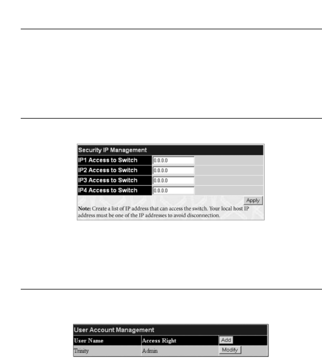
Chapter 7 - Security Management
7-1 Security IP
7-2 User Accounts
7-3 Access Authentication Control (TACACS)
7-4 Secure Sockets Layer (SSL)
7-5 Secure Shell (SSH)
The following section will aid the user in configuring security functions for the Switch.The Switch includes various functions for security, including TACACS,
Security IPs,SSL, and SSH, all discussed in detail in the following section.
7-1 Security IP
Go to the Security Management folder and click on the Security IP link; the following screen will appear.
Figure 7- 1. Security IP Management window
Use the Security IP Management window to permit remote stations to manage the Switch. If you choose to define one or more designated management
stations, only the chosen stations, as defined by IP address, will be allowed management privilege through the web manager or Telnet session.To define a
management station IP setting, type in the IP address and click the Apply button.
7-2 User Accounts
Use the User Accounts Management window to control user privileges.To view existing User Accounts, open the Security Management folder and
click on the User Accounts link.This will open the User Account Management page, as shown below.
Figure 7- 2. User Account Management Table
T
o add a new user, click on the Add button.T
o modify or delete an existing user, click on the Modify button for that user.
133
Allied Telesyn AT-9724TS High-Density Layer 3 Stackable Gigabit Ethernet Switch

Figure 7- 3. User Accounts Modify Table – Add
Add a new user by typing in a User Name,and New Password and retype the same password in the Confirm New Password.Choose the level of
privilege (Admin or User) from the Access Right drop-down menu.
Figure 7- 4. User Account Modify Table – Modify
Modify or delete an existing user account in the User Account Modify Table.To delete the user account, click on the Delete button.To change the
password, type in the New Passwordand retype it in the Confirm New Passwordentry field.The level of privilege (Admin or User) can be viewed in the
Access Right field.
Admin and User Privileges
There are two levels of user privileges, Admin and User.Some menu selections available to users with Admin privileges may not be available to those with
User privileges.
The following table summarizes the Admin and User privileges:
Management Admin User
Configuration Yes Read Only
Network Monitoring Yes Read Only
Community Strings and Trap Stations Yes Read Only
Update Firmware and Configuration Files Yes No
System Utilities Yes No
Factory Reset Yes No
User Account Management
Add/Update/Delete User Accounts Yes No
View User Accounts Yes No
Table 7- 1.Admin and User Privileges
After establishing a User Account with Admin-level privileges, be sure to save the changes by opening the Maintenance folder, opening the Save Changes window
and clicking the Save Configuration button.
134
Allied Telesyn AT-9724TS High-Density Layer 3 Stackable Gigabit Ethernet Switch

7-3 Access Authentication Control
The TACACS / XTACACS / TACACS+ / RADIUS commands let you secure access to the Switch using the TACACS / XTACACS / TACACS+ / RADIUS
protocols.When a user logs in to the Switch or tries to access the administrator level privilege, he or she is prompted for a password. If TACACS / XTACACS /
TACACS+ / RADIUS authentication is enabled on the Switch, it will contact a TACACS / XTACACS / TACACS+ / RADIUS server to verify the user. If the user is
verified, he or she is granted access to the Switch.
There are currently three versions of the TACACS security protocol, each a separate entity.The Switch's software supports the following versions of TACACS:
•TACACS (Terminal Access Controller Access Control System) – Provides password checking and authentication, and notification of user actions for
security purposes utilizing via one or more centralized TACACS servers, utilizing the UDP protocol for packet transmission.
•Extended TACACS (XTACACS) – An extension of the TACACS protocol with the ability to provide more types of authentication requests and
more types of response codes than TACACS.This protocol also uses UDP to transmit packets.
•TACACS+ (Terminal Access Controller Access Control System plus) – Provides detailed access control for authentication for
network devices.TACACS+ is facilitated through Authentication commands via one or more centralized servers.The TACACS+ protocol encrypts all
traffic between the Switch and the TACACS+ daemon, using the TCP protocol to ensure reliable delivery.
In order for the TACACS / XTACACS / TACACS+ / RADIUS security function to work properly, a TACACS / XTACACS / TACACS+ / RADIUS server must be
configured on a device other than the Switch, called an Authentication Server Host and it must include usernames and passwords for authentication.When the
user is prompted by the Switch to enter usernames and passwords for authentication, the Switch contacts the TACACS / XTACACS / TACACS+ / RADIUS
server to verify, and the server will respond with one of three messages:
• The server verifies the username and password, and the user is granted normal user privileges on the Switch.
• The server will not accept the username and password and the user is denied access to the Switch.
• The server doesn't respond to the verification query. At this point, the Switch receives the timeout from the server and then moves to the next
method of verification configured in the method list.
The Switch has four built-in Authentication Server Groups, one for each of the TACACS, XTACACS,TACACS+ and RADIUS protocols.These built-in
Authentication Server Groups are used to authenticate users trying to access the Switch.The users will set Authentication Server Hosts in a preferable
order in the built-in Authentication Server Groups and when a user tries to gain access to the Switch, the Switch will ask the first Authentication Server Hosts
for authentication. If no authentication is made, the second server host in the list will be queried, and so on.The built-in Authentication Server Groups can only
have hosts that are running the specified protocol. For example, the TACACS Authentication Server Groups can only have TACACS Authentication Server Hosts.
The administrator for the Switch may set up 6 different authentication techniques per user-defined method list (TACACS / XTACACS / TACACS+ / RADIUS /
local / none) for authentication.These techniques will be listed in an order preferable, and defined by the user for normal user authentication on the Switch, and
may contain up to eight authentication techniques.When a user attempts to access the Switch, the Switch will select the first technique listed for authentication.
If the first technique goes through its Authentication Server Hosts and no authentication is returned, the Switch will then go to the next technique listed in the
server group for authentication, until the authentication has been verified or denied, or the list is exhausted.
Please note that users granted access to the Switch will be granted normal user privileges on the Switch.To gain access to administrator level privileges, the user
must access the Enable Admin window and then enter a password, which was previously configured by the administrator of the Switch.
Note: TACACS, XTACACS and TACACS+ are separate entities and are not compatible.The Switch and the server must be configured exactly the
same, using the same protocol. (For example, if the Switch is set up for TACACS authentication, so must be the host server.)
Policy & Parameters
This command will enable an administrator-defined authentication policy for users trying to access the Switch.When enabled, the device will check the Login
Method List and choose a technique for user authentication upon login.
T
o access the following window, click Security Management > Access Authentication Control > Policy & Parameters:
Figure 7- 5. Policy & Parameters Settings window
135
Allied Telesyn AT-9724TS High-Density Layer 3 Stackable Gigabit Ethernet Switch

Figure 7- 7.Authentication Server Group Settings window
This screen displays the Authentication Server Groups on the Switch.The Switch has four built-in Authentication Server Groups that cannot be removed but can
be modified.To modify a particular group, click its hyperlinked Group Name, which will then display the following window.
Figure 7- 8.Add a Server Host to Server Group (XTACACS) window.
To add an Authentication Server Host to the list, enter its IP address in the IP Address field, choose the protocol associated with the IP address of the
Authentication Server Host and click ADD to Group to add this Authentication Server Host to the group.
To add a server group other than the ones listed, click the add button, revealing the following window to configure.
Figure 7- 9.Authentication Server Group Table Add Settings window
Enter a group name of up to 15 characters into the Group Name field and click Apply.The entry should appear in the Authentication Server Group
Settings window, as shown in Figure 7-7 (trinity).
Note: The user must configure Authentication Server Hosts using the Authentication Server Hosts window before adding hosts to the list.
Authentication Server Hosts must be configured for their specific protocol on a remote centralized server before this function can work properly.
Note: The built-in server groups can only have server hosts running the same TACACS or RADIUS daemon.TACACS/XTACACS/TACACS+
protocols are separate entities and are not compatible with each other.
137
Allied Telesyn AT-9724TS High-Density Layer 3 Stackable Gigabit Ethernet Switch

Authentication Server Hosts
This window will set user-defined Authentication Server Hosts for the TACACS / XTACACS / TACACS+ / RADIUS security protocols on the Switch.When
a user attempts to access the Switch with Authentication Policy enabled, the Switch will send authentication packets to a remote TACACS / XTACACS /
TACACS+ / RADIUS server host on a remote host.The TACACS / XTACACS / TACACS+ / RADIUS server host will then verify or deny the request and return
the appropriate message to the Switch. More than one authentication protocol can be run on the same physical server host but, remember that TACACS /
XTACACS / TACACS+ / RADIUS are separate entities and are not compatible with each other.The maximum supported number of server hosts is 16.
To view the following window, click Security Management > Access Authentication Control > Authentication Server Host:
Figure 7- 10.Authentication Server Host Settings window
To add an Authentication Server Host, click the Add button, revealing the following window:
Figure 7- 11.Authentication Server Host Setting window – Add
Configure the following parameters to add an Authentication Server Host:
Parameter Description
IP Address The IP address of the remote server host the user wishes to add.
Protocol The protocol used by the server host.The user may choose one of the following:
TACACS – Enter this parameter if the server host utilizes the TACACS protocol.
XTACACS – Enter this parameter if the server host utilizes the XTACACS protocol.
TACACS+ – Enter this parameter if the server host utilizes the TACACS+ protocol.
RADIUS – Enter this parameter if the server host utilizes the RADIUS protocol.
Port (1-65535) Enter a number between 1 and 65535 to define the virtual port number of the authentication protocol on a
server host.The default port number is 49 for TACACS/XTACACS/TACACS+ servers and 1813 for RADIUS
servers but the user may set a unique port number for higher security.
Timeout (1-255) Enter the time in seconds the Switch will wait for the server host to reply to an authentication request.The
default value is 5 seconds.
Retransmit (1-255) Enter the value in the retransmit field to change how many times the device will resend an authentication
request when the TACACS server does not respond.
Key Authentication key to be shared with a configured TACACS+ or RADIUS servers only. Specify an alphanumeric
string up to 254 characters.
Click Apply to add the server host.
138
Allied Telesyn AT-9724TS High-Density Layer 3 Stackable Gigabit Ethernet Switch

Note: More than one authentication protocol can be run on the same physical server host but, remember that TACACS/XTACACS/TACACS+
are separate entities and are not compatible with each other.
Login Method Lists
This command will configure a user-defined or default Login Method List of authentication techniques for users logging on to the Switch.The sequence of
techniques implemented in this command will affect the authentication result. For example, if a user enters a sequence of techniques, for example TACACS -
XTACACS- local, the Switch will send an authentication request to the first TACACS host in the server group. If no response comes from the server host, the
Switch will send an authentication request to the second TACACS host in the server group and so on, until the list is exhausted.At that point, the Switch will
restart the same sequence with the following protocol listed, XTACACS. If no authentication takes place using the XTACACS list, the local account database set
in the Switch is used to authenticate the user.When the local method is used, the privilege level will be dependant on the local account privilege configured on
the Switch.
Successful login using any of these techniques will give the user a "User" privilege only. If the user wishes to upgrade his or her status to the administrator level,
the user must use the Enable Admin window, in which the user must enter a previously configured password, set by the administrator. (See the Enable
Admin part of this section for more detailed information concerning the Enable Admin command.)
To view the following screen click Security Management > Access Authentication Control > Login Method Lists:
Figure 7- 12. Login Method Lists Settings window
The Switch contains one Method List that is set and cannot be removed, yet can be modified.To delete a Login Method List defined by the user, click the
8 under the Delete heading corresponding to the entry desired to be deleted.To modify a Login Method List, click on its hyperlinked Method List Name.
To configure a new Method List, click the Add button.
Both actions will result in the same screen to configure:
Figure 7- 13. Login Method List – Edit (default)
Figure 7- 14. Login Method List – Add
139
Allied Telesyn AT-9724TS High-Density Layer 3 Stackable Gigabit Ethernet Switch

Figure 7- 16. Enable Method List – Edit window
Figure 7- 17. Enable Method List – Add window
To define an Enable Login Method List, set the following parameters and click Apply:
Parameter Description
Method List Name Enter a method list name defined by the user of up to 15 characters.
Method 1, 2, 3, 4 The user may add one, or a combination of up to four (4) of the following authentication methods to this
method list:
local_enable – Adding this parameter will require the user to be authenticated using the local enable password
database on the Switch.The local enable password must be set by the user in the next section entitled Local
Enable Password.
none – Adding this parameter will require no authentication to access the Switch.
radius – Adding this parameter will require the user to be authenticated using the RADIUS protocol from a
remote RADIUS server.
tacacs – Adding this parameter will require the user to be authenticated using the TACACS protocol from a
remote TACACS server.
xtacacs – Adding this parameter will require the user to be authenticated using the XTACACS protocol from a
remote XTACACS server.
tacacs+ – Adding this parameter will require the user to be authenticated using the TACACS protocol from a
remote TACACS server.
server_group – Adding a previously configured server group will require the user to be authenticated using a
user-defined server group previously configured on the Switch.
Local Enable Password
This window will configure the locally enabled password for the Enable Admin command.When a user chooses the "local_enable" method to promote user
level privileges to administrator privileges, he or she will be prompted to enter the password configured here that is locally set on the Switch.
To view the following window, click Security Management > Access Authentication Control > Local Enable Password:
141
Allied Telesyn AT-9724TS High-Density Layer 3 Stackable Gigabit Ethernet Switch
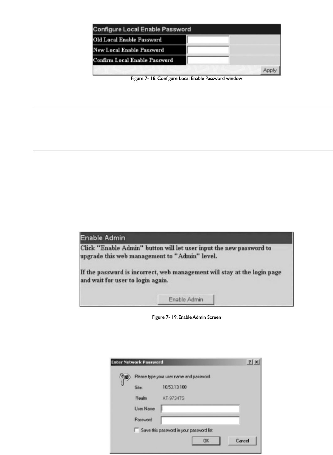
Figure 7- 18. Configure Local Enable Password window
To set the Local Enable Password, set the following parameters and click Apply.
Parameter Description
Old Local Enable Password If a password was previously configured for this entry, enter it here in order to change it to a new password.
New Local Enable Password Enter the new password that you wish to set on the Switch to authenticate users attempting to access
Administrator Level privileges on the Switch.The user may set a password of up to 15 characters.
Confirm Local Enable Password Confirm the new password entered above. Entering a different password here from the one set in the New
Local Enabled field will result in a fail message.
Enable Admin
The Enable Admin window is for users who have logged on to the Switch on the normal user level, and wish to be promoted to the administrator level.After
logging on to the Switch, users will have only user level privileges.To gain access to administrator level privileges, the user will open this window and will have to
enter an authentication password. Possible authentication methods for this function include TACACS/XTACACS/TACACS+/RADIUS, user defined server groups,
local enable (local account on the Switch), or no authentication (none). Because XTACACS and TACACS do not support the enable function, the user must
create a special account on the server host, which has the username "enable", and a password configured by the administrator that will support the "enable"
function.This function becomes inoperable when the authentication policy is disabled.
To view the following window, click Security Management > Access Authentication Control > Enable Admin:
Figure 7- 19. Enable Admin Screen
When this screen appears, click the Enable Admin button revealing a window for the user to enter authentication (password, username), as seen below.
A successful entry will promote the user to Administrator level privileges on the Switch.
Figure 7- 20. Enter Network Password window
142
Allied Telesyn AT-9724TS High-Density Layer 3 Stackable Gigabit Ethernet Switch

7-4 Secure Socket Layer (SSL)
Secure Sockets Layer or SSL is a security feature that will provide a secure communication path between a host and client through the use of authentication, digital
signatures and encryption.These security functions are implemented through the use of a ciphersuite, which is a security string that determines the exact
cryptographic parameters, specific encryption algorithms and key sizes to be used for an authentication session and consists of three levels:
1. Key Exchange:The first part of the ciphersuite string specifies the public key algorithm to be used.This Switch utilizes the Rivest Shamir Adleman
(RSA) public key algorithm and the Digital Signature Algorithm (DSA), specified here as the DHE DSS Diffie-Hellman (DHE) public key algorithm.This
is the first authentication process between client and host as they “exchange keys” in looking for a match and therefore authentication to be accepted
to negotiate encryptions on the following level.
2. Encryption:The second part of the ciphersuite that includes the encryption used for encrypting the messages sent between client and host.The
Switch supports two types of cryptology algorithms:
Stream Ciphers – There are two types of stream ciphers on the Switch, RC4 with 40-bit keys and RC4 with 128-bit keys.These keys are used to encrypt
messages and need to be consistent between client and host for optimal use.
CBC Block Ciphers – CBC refers to Cipher Block Chaining, which means that a portion of the previously encrypted block of encrypted text is used
in the encryption of the current block.The Switch supports the 3DES EDE encryption code defined by the Data Encryption Standard (DES) to create
the encrypted text.
3. Hash Algorithm:This part of the ciphersuite allows the user to choose a message digest function which will determine a Message Authentication
Code.This Message Authentication Code will be encrypted with a sent message to provide integrity and prevent against replay attacks.The Switch
supports two hash algorithms, MD5 (Message Digest 5) and SHA (Secure Hash Algorithm).
These three parameters are uniquely assembled in four choices on the Switch to create a three-layered encryption code for secure communication between the
server and the host.The user may implement any one or combination of the ciphersuites available, yet different ciphersuites will affect the security level and the
performance of the secured connection.The information included in the ciphersuites is not included with the Switch and requires downloading from a third
source in a file form called a certificate.This function of the Switch cannot be executed without the presence and implementation of the certificate file and can be
downloaded to the Switch by utilizing a TFTP server.The Switch supports SSLv3 and TLSv1. Other versions of SSL may not be compatible with this Switch and
may cause problems upon authentication and transfer of messages from client to host.
Download Certificate
This window is used to download a certificate file for the SSL function on the Switch from a TFTP server.The certificate file is a data record used for
authenticating devices on the network. It contains information on the owner, keys for authentication and digital signatures. Both the server and the client must
have consistent certificate files for optimal use of the SSL function.The Switch only supports certificate files with .der file extensions.
To view the following window, click Security Management > Secure Socket Layer (SSL) > Download Certificate:
Figure 7- 21. Download Certificate window
To download certificates, set the following parameters and click Apply.
Parameter Description
Certificate Type Enter the type of certificate to be downloaded.This type refers to the server responsible for issuing
certificates.This field has been limited to local for this firmware release.
Server IP Enter the IP address of the TFTP server where the certificate files are located.
Certificate File Name Enter the path and the filename of the certificate file to download.This file must have a .der extension. (Ex.
c:/cert.der).
Key File Name Enter the path and the filename of the key file to download.This file must have a .der extension (Ex.
c:/pkey.der).
143
Allied Telesyn AT-9724TS High-Density Layer 3 Stackable Gigabit Ethernet Switch

Configuration
This screen will allow the user to enable SSL on the Switch and implement any one or combination of listed ciphersuites on the Switch.A ciphersuite is a
security string that determines the exact cryptographic parameters, specific encryption algorithms and key sizes to be used for an authentication session.The
Switch possesses four possible ciphersuites for the SSL function, which are all enabled by default.To utilize a particular ciphersuite, disable the unwanted
ciphersuites, leaving the desired one for authentication.
When the SSL function has been enabled, the web will become disabled.To manage the Switch through the web based management while utilizing the SSL
function, the web browser must support SSL encryption and the header of the URL must begin with https://. (Ex. https://10.90.90.90) Any other method will
result in an error and no access can be authorized for the web-based management.
To view the following window, click Security Management > Secure Socket Layer (SSL) > Configuration:
Figure 7- 22. Configuration and Ciphersuite window
To set up the SSL function on the Switch, configure the following parameters and click Apply.
Parameter Description
Configuration
SSL Status Use the pull down menu to enable or disable the SSL status on the switch.The default is Disabled.
Cache Timeout (60-84600) This field will set the time between a new key exchange between a client and a host using the SSL function.A
new SSL session is established every time the client and host go through a key exchange. Specifying a longer
timeout will allow the SSL session to reuse the master key on future connections with that particular host,
therefore speeding up the negotiation process.The default setting is 600 seconds.
Ciphersuite
RSA with RC4 128 MD5 This ciphersuite combines the RSA key exchange, stream cipher RC4 encryption with 128-bit keys and the
MD5 Hash Algorithm. Use the pull down menu to enable or disable this ciphersuite.This field is Enabled by
default.
RSA with 3DES EDE CBC SHA This ciphersuite combines the RSA key exchange,CBC Block Cipher 3DES_EDE encryption and the SHA Hash
Algorithm. Use the pull down menu to enable or disable this ciphersuite.This field is Enabled by default.
DHS DSS with 3DES EDE
CBC SHA This ciphersuite combines the DSA Diffie Hellman key exchange, CBC Block Cipher 3DES_EDE encryption and
SHA Hash Algorithm. Use the pull down menu to enable or disable this ciphersuite.This field is Enabled by
default.
RSA EXPORT with RC4 40 MD5 This ciphersuite combines the RSA Export key exchange and stream cipher RC4 encryption with 40-bit keys.
Use the pull down menu to enable or disable this ciphersuite.This field is Enabled by default.
Note: Certain implementations concerning the function and configuration of SSL are not available on the web-based management of this Switch
and need to be configured using the command line interface. For more information on SSL and its functions, see the AT-9724TS Command Line
Reference Manual,located on the documentation CD of this product.
Note: Enabling the SSL command will disable the web-based switch management.To log on to the Switch again, the header of the URL must begin
with https://. Entering anything else into the address field of the web browser will result in an error and no authentication will be granted.
144
Allied Telesyn AT-9724TS High-Density Layer 3 Stackable Gigabit Ethernet Switch

7-5 Secure Shell (SSH)
SSH is an abbreviation of Secure Shell, which is a program allowing secure remote login and secure network services over an insecure network. It allows a
secure login to remote host computers, a safe method of executing commands on a remote end node, and will provide secure encrypted and authenticated
communication between two non-trusted hosts. SSH, with its array of unmatched security features is an essential tool in today’s networking environment. It is a
powerful guardian against numerous existing security hazards that now threaten network communications.
The steps required to use the SSH protocol for secure communication between a remote PC (the SSH client) and the Switch (the SSH server) are as follows:
1. Create a user account with admin-level access using the User Accounts window in the Security Management folder.This is identical to creating any
other admin-level User Account on the Switch, including specifying a password.This password is used to logon to the Switch, once a secure
communication path has been established using the SSH protocol.
2. Configure the User Account to use a specified authorization method to identify users that are allowed to establish SSH connections with the Switch
using the SSH User Authentication window.There are three choices as to the method SSH will use to authorize the user, which are Host
Based,Password and Public Key.
3. Configure the encryption algorithm that SSH will use to encrypt and decrypt messages sent between the SSH client and the SSH server, using the SSH
Algorithm window.
4. Finally, enable SSH on the Switch using the SSH Configuration window.
After completing the preceding steps, a SSH Client on a remote PC can be configured to manage the Switch using a secure, in band connection.
SSH Configuration
The following window is used to configure and view settings for the SSH server and can be opened by clicking Security Management > Secure Shell
(SSH) > SSH Configuration:
Figure 7- 23. Current and New SSH Configuration Settings
T
o configure the SSH server on the Switch, modify the following parameters and click Apply:
Parameter Description
SSH Server Status Use the pull-down menu to enable or disable SSH on the Switch.The default is Disabled.
Max Session (1-3) Enter a value between 1 and 3 to set the number of users that may simultaneously access the Switch.The
default setting is 3.
Connection TimeOut (120-600) Allows the user to set the connection timeout.The use may set a time between 120 and 600 seconds.The
default setting is 120 seconds.
Auth. Fail (2-20) Allows the Administrator to set the maximum number of attempts that a user may try to log on to the SSH
Server utilizing the SSH authentication.After the maximum number of attempts has been exceeded, the Switch
will be disconnected and the user must reconnect to the Switch to attempt another login.The number of
maximum attempts may be set between 2 and 20.The default setting is 2.
Session Rekeying This field is used to set the time period that the Switch will change the security shell encryptions by using the
pull-down menu.The available options are Never, 10 min, 30 min, and 60 min.The default setting is Never.
SSH Algorithm
The SSH Algorithm window allows the configuration of the desired types of SSH algorithms used for authentication encryption.There are three categories of
algorithms listed and specific algorithms of each may be enabled or disabled by using their corresponding pull-down menus.All algorithms are enabled by default.
To open the following window, click Security Management > Secure Shell (SSH) > SSH Algorithm:
145
Allied Telesyn AT-9724TS High-Density Layer 3 Stackable Gigabit Ethernet Switch

Figure 7- 24. SSH Algorithms window
The following algorithms may be set:
Parameter Description
Authentication Mode Configuration
Password This field may be enabled or disabled to choose if the administrator wishes to use a locally configured
password for authentication on the Switch.This field is Enabled by default.
Public Key This field may be enabled or disabled to choose if the administrator wishes to use a publickey configuration set
on a SSH server, for authentication.This field is Enabled by default.
Host-based This field may be enabled or disabled to choose if the administrator wishes to use a host computer for
authentication.This parameter is intended for Linux users requiring SSH authentication techniques and the host
computer is running the Linux operating system with a SSH program previously installed.This field is Enabled by
default.
Encryption Algorithm
3DES-CBC Use the pull-down to enable or disable the Triple Data Encryption Standard encryption algorithm with Cipher
Block Chaining.The default is Enabled.
Blow-fish CBC Use the pull-down to enable or disable the Blowfish encryption algorithm with Cipher Block Chaining.The
default is Enabled.
AES128-CBC Use the pull-down to enable or disable the Advanced Encryption Standard AES128 encryption algorithm with
Cipher Block Chaining.The default is Enabled.
AES192-CBC Use the pull-down to enable or disable the Advanced Encryption Standard AES192 encryption algorithm with
Cipher Block Chaining.The default is Enabled.
AES256-CBC Use the pull-down to enable or disable the Advanced Encryption Standard AES-256 encryption algorithm with
Cipher Block Chaining.The default is Enabled.
ARC4 Use the pull-down to enable or disable the Arcfour encryption algorithm with Cipher Block Chaining.The
default is Enabled.
Cast128-CBC Use the pull-down to enable or disable the Cast128 encryption algorithm with Cipher Block Chaining.The
default is Enabled.
Twofish128 Use the pull-down to enable or disable the twofish128 encryption algorithm.The default is Enabled.
Twofish192 Use the pull-down to enable or disable the twofish192 encryption algorithm.The default is Enabled.
Twofish256 Use the pull-down to enable or disable the twofish256 encryption algorithm.The default is Enabled.
146
Allied Telesyn AT-9724TS High-Density Layer 3 Stackable Gigabit Ethernet Switch

Parameter Description
User Name Enter a User Name of no more than 15 characters to identify the SSH user.This User Name must be a
previously configured user account on the Switch.
Auth. Mode The administrator may choose one of the following to set the authorization for users attempting to access the
Switch.
Host Based – This parameter should be chosen if the administrator wishes to use a remote SSH server for
authentication purposes. Choosing this parameter requires the user to input the following information to
identify the SSH user.
Host Name – Enter an alphanumeric string of no more than 32 characters to identify the remote SSH
user.
Host IP – Enter the corresponding IP address of the SSH user.
Password – This parameter should be chosen if the administrator wishes to use an administrator-defined
password for authentication. Upon entry of this parameter, the Switch will prompt the administrator for a
password, and then to re-type the password for confirmation.
Public Key – This parameter should be chosen if the administrator wishes to use the publickey on a SSH server
for authentication.
Host Name Enter an alphanumeric string of no more than 32 characters to identify the remote SSH user.This parameter is
only used in conjunction with the Host Based choice in the Auth. Mode field.
Host IP Enter the corresponding IP address of the SSH user.This parameter is only used in conjunction with the Host
Based choice in the Auth. Mode field.
Click Apply to implement changes made.
Note: To set the SSH User Authentication parameters on the Switch, a User Account must be previously configured. For more information
on configuring local User Accounts on the Switch, see the User Accounts section of this manual located in this section.
148
Allied Telesyn AT-9724TS High-Density Layer 3 Stackable Gigabit Ethernet Switch

Chapter 8 - SNMP Manager
SNMP Settings
Simple Network Management Protocol (SNMP) is an OSI Layer 7 (Application Layer) designed specifically for managing and monitoring network devices. SNMP
enables network management stations to read and modify the settings of gateways, routers, switches, and other network devices. Use SNMP to configure system
features for proper operation, monitor performance and detect potential problems in the Switch, switch group or network.
Managed devices that support SNMP include software (referred to as an agent), which runs locally on the device.A defined set of variables (managed objects) is
maintained by the SNMP agent and used to manage the device.These objects are defined in a Management Information Base (MIB), which provides a standard
presentation of the information controlled by the on-board SNMP agent. SNMP defines both the format of the MIB specifications and the protocol used to
access this information over the network.
The AT-9724TS supports the SNMP versions 1, 2c, and 3.You can specify which version of the SNMP you want to use to monitor and control the Switch.The
three versions of SNMP vary in the level of security provided between the management station and the network device.
In SNMP v.1 and v.2, user authentication is accomplished using 'community strings', which function like passwords.The remote user SNMP application and the
Switch SNMP must use the same community string. SNMP packets from any station that has not been authenticated are ignored (dropped).
The default community strings for the Switch used for SNMP v1 and v2 management access are:
public – Allows authorized management stations to retrieve MIB objects.
private – Allows authorized management stations to retrieve and modify MIB objects.
SNMPv3 uses a more sophisticated authentication process that is separated into two parts.The first part is to maintain a list of users and their attributes that are
allowed to act as SNMP managers.The second part describes what each user on that list can do as an SNMP manager.
The Switch allows groups of users to be listed and configured with a shared set of privileges.The SNMP version may also be set for a listed group of SNMP
managers.Thus, you may create a group of SNMP managers that are allowed to view read-only information or receive traps using SNMPv1 while assigning a
higher level of security to another group, granting read/write privileges using SNMPv3.
Using SNMPv3 individual users or groups of SNMP managers can be allowed to perform or be restricted from performing specific SNMP management functions.
The functions allowed or restricted are defined using the Object Identifier (OID) associated with a specific MIB.An additional layer of security is available for
SNMPv3 in that SNMP messages may be encrypted.To read more about how to configure SNMPv3 settings for the Switch read the next section.
Traps
Traps are messages that alert network personnel of events that occur on the Switch.The events can be as serious as a reboot (someone accidentally turned OFF
the Switch), or less serious like a port status change.The Switch generates traps and sends them to the trap recipient (or network manager).Typical traps include
trap messages for Authentication Failure,Topology Change and Broadcast\Multicast Storm.
MIBs
Management and counter information are stored by the Switch in the Management Information Base (MIB).The Switch uses the standard MIB-II Management
Information Base module. Consequently, values for MIB objects can be retrieved from any SNMP-based network management software. In addition to the
standard MIB-II, the Switch also supports its own proprietary enterprise MIB as an extended Management Information Base.The proprietary MIB may also be
retrieved by specifying the MIB Object Identifier. MIB values can be either read-only or read-write.
The AT-9724TS incorporates a flexible SNMP management for the switching environment. SNMP management can be customized to suit the needs of the
networks and the preferences of the network administrator. Use the SNMP V3 menus to select the SNMP version used for specific tasks.
The AT-9724TS supports the Simple Network Management Protocol (SNMP) versions 1, 2c, and 3.The administrator can specify the SNMP version used to
monitor and control the Switch.The three versions of SNMP vary in the level of security provided between the management station and the network device.
SNMP settings are configured using the menus located on the SNMP V3 folder of the web manager.Workstations on the network that are allowed SNMP
privileged access to the Switch can be restricted with the Management Station IP Address menu.
SNMP User Table
The SNMP User Table displays all of the SNMP User's currently configured on the Switch.
In the SNMP Manager folder, click on the SNMP User Table link.This will open the SNMP User Table, as shown below.
Figure 8- 1. SNMP User Table
To delete an existing SNMP User Table entry, click the 8 below the Delete heading corresponding to the entry you wish to delete.
149
Allied Telesyn AT-9724TS High-Density Layer 3 Stackable Gigabit Ethernet Switch

To display the detailed entry for a given user, click on the hyperlinked User Name.This will open the SNMP User Table Display page, as shown below.
Figure 8- 2. SNMP User Table Display window
The following parameters are displayed:
Parameter Description
User Name An alphanumeric string of up to 32 characters.This is used to identify the SNMP users.
Group Name This name is used to specify the SNMP group created can request SNMP messages.
SNMP Version V1 – Indicates that SNMP version 1 is in use.
V2 – Indicates that SNMP version 2 is in use.
V3 – Indicates that SNMP version 3 is in use.
Auth-Protocol None – Indicates that no authorization protocol is in use.
MD5 – Indicates that the HMAC-MD5-96 authentication level will be used.
SHA – Indicates that the HMAC-SHA authentication protocol will be used.
Priv-Protocol None – Indicates that no authorization protocol is in use.
DES – Indicates that DES 56-bit encryption is in use based on the CBC-DES (DES-56) standard.
To return to the SNMP User Table, click the Show All SNMP User Table Entries link.
To add a new entry to the SNMP User Table Configuration, click on the Add button on the SNMP User Table page.
This will open the SNMP User Table Configuration page, as shown below.
Figure 8- 3. SNMP User Table Configuration window
The following parameters can be set:
150
Allied Telesyn AT-9724TS High-Density Layer 3 Stackable Gigabit Ethernet Switch

Parameter Description
User Name Enter an alphanumeric string of up to 32 characters.This is used to identify the SNMP user.
Group Name This name is used to specify the SNMP group created can request SNMP messages.
SNMP Version V1 – Specifies that SNMP version 1 will be used.
V2 – Specifies that SNMP version 2 will be used.
V3 – Specifies that SNMP version 3 will be used.
Auth-Protocol MD5 – Specifies that the HMAC-MD5-96 authentication level will be used.This field is only operable when V3 is
selected in the SNMP Version field and the Encryption field has been checked.This field will require the
user to enter a password.
SHA – Specifies that the HMAC-SHA authentication protocol will be used.This field is only operable when V3 is
selected in the SNMP Version field and the Encryption field has been checked.This field will require the
user to enter a password.
Priv-Protocol None – Specifies that no authorization protocol is in use.
DES – Specifies that DES 56-bit encryption is in use, based on the CBC-DES (DES-56) standard.This field is
only operable when V3 is selected in the SNMP Version field and the Encryption field has been checked.
This field will require the user to enter a password between 8 and 16 alphanumeric characters.
Encrypted Checking the corresponding box will enable encryption for SNMP V3 and is only operable in SNMP V3 mode.
To implement changes made, click Apply.To return to the SNMP User Table, click the Show All SNMP User Table Entries link.
SNMP View Table
The SNMP View Table is used to assign views to community strings that define which MIB objects can be accessed by a remote SNMP manager.To view the
SNMP View Table, open the SNMP Manager folder and click the SNMP View Table entry.The following screen should appear:
Figure 8- 4. SNMP
View Table
T
o delete an existing SNMP View Table entry,click the 8in the Delete column corresponding to the entry you wish to delete.To create a new entry, click
the Add button and a separate menu will appear.
151
Allied Telesyn AT-9724TS High-Density Layer 3 Stackable Gigabit Ethernet Switch
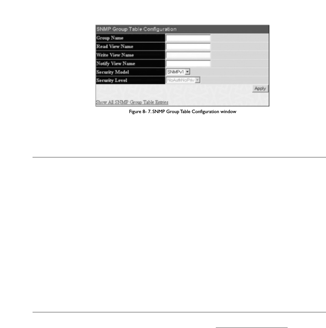
Figure 8- 7. SNMP Group Table Configuration window
The following parameters can be set:
Parameter Description
Group Name Type an alphanumeric string of up to 32 characters.This is used to identify the new SNMP group of SNMP
users.
Read View Name This name is used to specify the SNMP group created can request SNMP messages.
Write View Name Specify a SNMP group name for users that are allowed SNMP write privileges to the Switch's SNMP agent.
Notify View Name Specify a SNMP group name for users that can receive SNMP trap messages generated by the Switch's SNMP
agent.
Security Model SNMPv1 – Specifies that SNMP version 1 will be used.
SNMPv2 – Specifies that SNMP version 2c will be used.The SNMPv2 supports both centralized and distributed
network management strategies. It includes Read View Name improvements in the Structure of Management
Information (SMI) and adds some security features.
SNMPv3 – Specifies that the SNMP version 3 will be used. SNMPv3 provides secure access to devices through a
combination of authentication and encrypting packets over the network.
Security Level The Security Level settings only apply to SNMPv3.
NoAuthNoPriv – Specifies that there will be no authorization and no encryption of packets sent between the
Switch and a remote SNMP manager.
AuthNoPriv – Specifies that authorization will be required, but there will be no encryption of packets sent
between the Switch and a remote SNMP manager.
AuthPriv – Specifies that authorization will be required, and that packets sent between the Switch and a remote
SNMP manger will be encrypted.
T
o implement your new settings, click Apply.T
o return to the SNMP Group Table,click the Show All SNMP Group Table Entries link.
SNMP Community Table Configuration
Use this table to create an SNMP community string to define the relationship between the SNMP manager and an agent.The community string acts like a
password to permit access to the agent on the Switch. One or more of the following characteristics can be associated with the community string:
• An Access List of IP addresses of SNMP managers that are permitted to use the community string to gain access to the Switch's SNMP agent.
• Any MIB view that defines the subset of all MIB objects will be accessible to the SNMP community.
• Read/write or read-only level permission for the MIB objects accessible to the SNMP community.
To configure SNMP Community entries, open the SNMP Manager folder and click the SNMP Community Table link, which will open the following
screen:
153
Allied Telesyn AT-9724TS High-Density Layer 3 Stackable Gigabit Ethernet Switch

Figure 8-10. SNMP Host Table Configuration window
The following parameters can be set:
Parameter Description
Host IP Address Type the IP address of the remote management station that will serve as the SNMP host for the Switch.
SNMP Version V1 – To specifies that SNMP version 1 will be used.
V2 – To specify that SNMP version 2 will be used.
V3-NoAuth-NoPriv – To specify that the SNMP version 3 will be used, with a NoAuth-NoPriv security level.
V3-Auth-NoPriv – To specify that the SNMP version 3 will be used, with an Auth-NoPriv security level.
V3-Auth-Priv – To specify that the SNMP version 3 will be used, with an Auth-Priv security level.
Community String or
SNMP V3 User Name Type in the community string or SNMP V3 user name as appropriate.
To implement your new settings, click Apply.To return to the SNMP Host Table, click the Show All SNMP Host Table Entries link.
SNMP Engine ID
The Engine ID is a unique identifier used for SNMP V3 implementations.This is an alphanumeric string used to identify the SNMP engine on the Switch.
To display the Switch's SNMP Engine ID, open the SNMP Manager folder and click on the SNMP Engine ID link.This will open the SNMP Engine ID
Configuration window,as shown below.
Figure 8-11. SNMP Engine ID Configuration window
T
o change the Engine ID, type the new Engine ID in the space provided and click the Apply button.
155
Allied Telesyn AT-9724TS High-Density Layer 3 Stackable Gigabit Ethernet Switch

Chapter 9 - Monitoring
9-1 Port Utilization
The Port Utilization page displays the percentage of the total available bandwidth being used on the port.
To view the port utilization, open the Monitoring folder and then the Port Utilization link:
Figure 9- 1. Port Utilization window
To select a port to view these statistics for, first select the Switch in the switch stack by using the Unit pull-down menu and then select the port by using the
Port pull down menu.The user may also use the real-time graphic of the Switch and/or switch stack at the top of the web page by simply clicking on a port.
The following fields can be set:
Parameter Description
Time Interval Select the desired setting between 1s and 60s, where "s" stands for seconds.The default value is one second.
Record Number Select number of times the Switch will be polled between 20 and 200.The default value is 200.
Click Clear to refresh the graph. Click Apply to set changes implemented.
9-2 CPU Utilization
The CPU Utilization displays the percentage of the CPU being used, expressed as an integer percentage and calculated as a simple average by time interval.To
view the CPU Utilization window, open the Monitoring folder and click the CPU Utilization link.
156
Allied Telesyn AT-9724TS High-Density Layer 3 Stackable Gigabit Ethernet Switch

Figure 9- 2. CPU Utilization graph
Click Apply to implement the configured settings.The window will automatically refresh with new updated statistics.
The information is described as follows:
Parameter Description
Time Interval Select the desired setting between 1s and 60s, where "s" stands for seconds.The default value is one second.
Record Number Select number of times the Switch will be polled between 20 and 200.The default value is 200.
Utilization Check whether or not to display Utilization.
9-3 Packets
The Web Manager allows various packet statistics to be viewed as either a line graph or a table. Six windows are offered.
Received (RX)
Click the Received (RX) link in the Packets folder of the Monitoring menu to view the following graph of packets received on the Switch.To select a port
to view these statistics for, first select the Switch in the switch stack by using the Unit pull-down menu and then select the port by using the Port pull down
menu.The user may also use the real-time graphic of the Switch and/or switch stack at the top of the web page by simply clicking on a port.
157
Allied Telesyn AT-9724TS High-Density Layer 3 Stackable Gigabit Ethernet Switch

Figure 9- 3. Rx Packets Analysis window (line graph for Bytes and Packets)
To view the Received Packets Table, click the link View Table, which will show the following table:
Figure 9- 4. Rx Packets Analysis window (table for Bytes and Packets)
The following fields may be set or viewed:
158
Allied Telesyn AT-9724TS High-Density Layer 3 Stackable Gigabit Ethernet Switch

Parameter Description
Time Interval Select the desired setting between 1s and 60s, where "s" stands for seconds.The default value is one second.
Record Number Select number of times the Switch will be polled between 20 and 200.The default value is 200.
Bytes Counts the number of bytes received on the port.
Packets Counts the number of packets received on the port.
Unicast Counts the total number of good packets that were received by a unicast address.
Multicast Counts the total number of good packets that were received by a multicast address.
Broadcast Counts the total number of good packets that were received by a broadcast address.
Show/Hide Check whether to display Bytes and Packets.
ClearClicking this button clears all statistics counters on this window.
View Table Clicking this button instructs the Switch to display a table rather than a line graph.
View Line Chart Clicking this button instructs the Switch to display a line graph rather than a table.
UMB Cast (RX)
Click the UMB Cast (RX) link in the Packets folder of the Monitoring menu to view the following graph of UMB cast packets received on the Switch.To
select a port to view these statistics for, first select the Switch in the switch stack by using the Unit pull-down menu and then select the port by using the Port
pull down menu.The user may also use the real-time graphic of the Switch and/or switch stack at the top of the web page by simply clicking on a port.
Figure 9- 5. Rx Packets Analysis window (line graph for Unicast, Multicast, and Broadcast Packets)
T
o view the UMB Cast Table,click the View Table link, which will show the following table:
159
Allied Telesyn AT-9724TS High-Density Layer 3 Stackable Gigabit Ethernet Switch

Figure 9- 6. Rx Packets Analysis window (table for Unicast, Multicast, and Broadcast Packets)
The following fields may be set or viewed:
Parameter Description
Time Interval Select the desired setting between 1s and 60s, where "s" stands for seconds.The default value is one second.
Record Number Select number of times the Switch will be polled between 20 and 200.The default value is 200.
Unicast Counts the total number of good packets that were received by a unicast address.
Multicast Counts the total number of good packets that were received by a multicast address.
Broadcast Counts the total number of good packets that were received by a broadcast address.
Show/Hide Check whether or not to display Multicast, Broadcast, and Unicast Packets.
ClearClicking this button clears all statistics counters on this window.
View Table Clicking this button instructs the Switch to display a table rather than a line graph.
View Line Chart Clicking this button instructs the Switch to display a line graph rather than a table.
Transmitted (TX)
Click the Transmitted (TX) link in the Packets folder of the Monitoring menu to view the following graph of packets transmitted from the Switch.To
select a port to view these statistics for, first select the Switch in the switch stack by using the Unit pull-down menu and then select the port by using the Port
pull down menu.The user may also use the real-time graphic of the Switch and/or switch stack at the top of the web page by simply clicking on a port.
160
Allied Telesyn AT-9724TS High-Density Layer 3 Stackable Gigabit Ethernet Switch

The following fields may be set or viewed:
Parameter Description
Time Interval Select the desired setting between 1s and 60s, where "s" stands for seconds.The default value is one second.
Record Number Select number of times the Switch will be polled between 20 and 200.The default value is 200.
Bytes Counts the number of bytes successfully sent from the port.
Packets Counts the number of packets successfully sent on the port.
Unicast Counts the total number of good packets that were transmitted by a unicast address.
Multicast Counts the total number of good packets that were transmitted by a multicast address.
Broadcast Counts the total number of good packets that were transmitted by a broadcast address.
Show/Hide Check whether or not to display Bytes and Packets.
Clear Clicking this button clears all statistics counters on this window.
View Table Clicking this button instructs the Switch to display a table rather than a line graph.
View Line Chart Clicking this button instructs the Switch to display a line graph rather than a table.
9-4 Errors
The Web Manager allows port error statistics compiled by the Switch's management agent to be viewed as either a line graph or a table. Four windows are
offered.
Received (RX)
Click the Received (RX) link in the Error folder of the Monitoring menu to view the following graph of error packets received on the Switch.To select a
port to view these statistics for, first select the Switch in the switch stack by using the Unit pull-down menu and then select the port by using the Port pull down
menu.The user may also use the real-time graphic of the Switch and/or switch stack at the top of the web page by simply clicking on a port.
Figure 9- 9. Rx Error Analysis window (line graph)
To view the Received Error Packets Table, click the link View Table, which will show the following table:
162
Allied Telesyn AT-9724TS High-Density Layer 3 Stackable Gigabit Ethernet Switch

Figure 9- 10. Rx Error Analysis window (table)
The following fields can be set:
Parameter Description
Time Interval Select the desired setting between 1s and 60s, where "s" stands for seconds.The default value is one second.
Record Number Select number of times the Switch will be polled between 20 and 200.The default value is 200.
Crc Error Counts otherwise valid packets that did not end on a byte (octet) boundary.
Under SizeThe number of packets detected that are less than the minimum permitted packets size of 64 bytes and have a
good CRC.Undersize packets usually indicate collision fragments, a normal network occurrence.
Over Size Counts packets received that were longer than 1518 octets, or if a VLAN frame is 1522 octets, and less than
the MAX_PKT_LEN. Internally, MAX_PKT_LEN is equal to 1522.
Fragment The number of packets less than 64 bytes with either bad framing or an invalid CRC.These are normally the
result of collisions.
Jabber The number of packets with lengths more than the MAX_PKT_LEN bytes. Internally, MAX_PKT_LEN is equal
to 1522.
Drop The number of packets that are dropped by this port since the last Switch reboot.
Show/Hide Check whether or not to display Crc Error, Under Size, Over Size, Fragment, Jabber, and Drop errors.
Clear Clicking this button clears all statistics counters on this window.
View Table Clicking this button instructs the Switch to display a table rather than a line graph.
View Line Chart Clicking this button instructs the Switch to display a line graph rather than a table.
Transmitted (TX)
Click the Transmitted (TX) link in the Error folder of the Monitoring menu to view the following graph of error packets received on the Switch.To select a port
to view these statistics for, first select the Switch in the switch stack by using the Unit pull-down menu and then select the port by using the Port pull down
menu.The user may also use the real-time graphic of the Switch and/or switch stack at the top of the web page by simply clicking on a port.
163
Allied Telesyn AT-9724TS High-Density Layer 3 Stackable Gigabit Ethernet Switch

Figure 9- 11.Tx Error Analysis window (line graph)
To view the Transmitted Error Packets Table, click the link View Table, which will show the following table:
Figure 9- 12.Tx Error Analysis window (table)
The following fields may be set or viewed:
164
Allied Telesyn AT-9724TS High-Density Layer 3 Stackable Gigabit Ethernet Switch
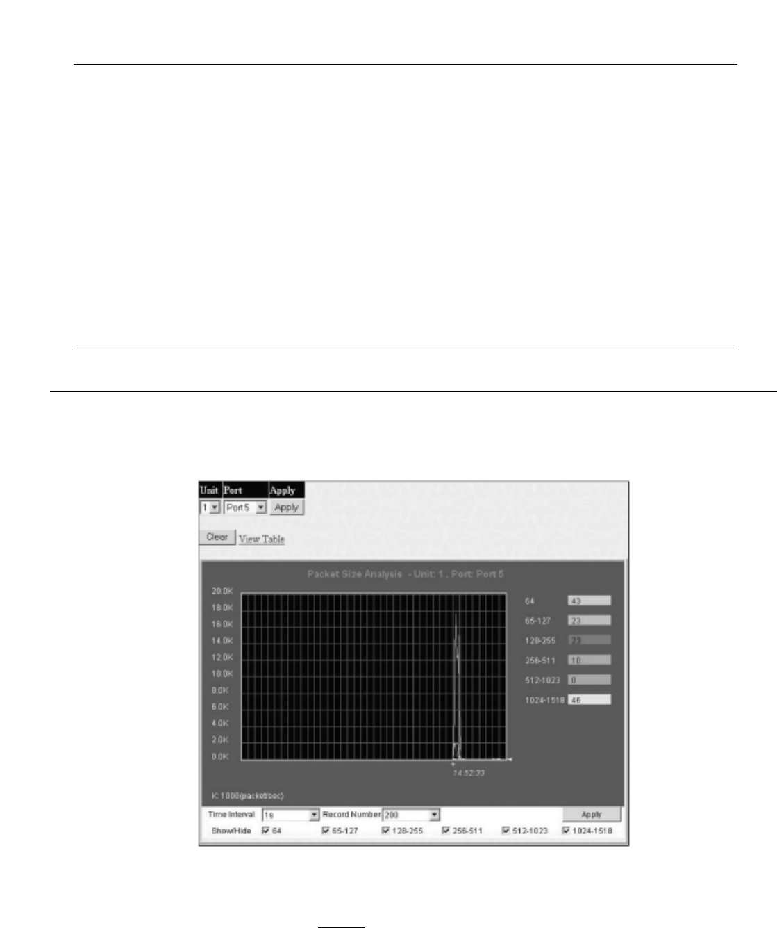
Parameter Description
Time Interval Select the desired setting between 1s and 60s, where "s" stands for seconds.The default value is one second.
Record Number Select number of times the Switch will be polled between 20 and 200.The default value is 200.
ExDefer Counts the number of packets for which the first transmission attempt on a particular interface was delayed
because the medium was busy.
LateColl Counts the number of times that a collision is detected later than 512 bit-times into the transmission of a
packet.
ExColl Excessive Collisions.The number of packets for which transmission failed due to excessive collisions.
SingColl Single Collision Frames.The number of successfully transmitted packets for which transmission is inhibited by
more than one collision.
Coll An estimate of the total number of collisions on this network segment.
Show/Hide Check whether or not to display ExDefer, LateColl, ExColl, SingColl, and Coll errors.
Clear Clicking this button clears all statistics counters on this window.
View Table Clicking this button instructs the Switch to display a table rather than a line graph.
View Line Chart Clicking this button instructs the Switch to display a line graph rather than a table.
9-5 Size
The Web Manager allows packets received by the Switch, arranged in six groups and classed by size, to be viewed as either a line graph or a table.Two windows
are offered.To select a port to view these statistics for, first select the Switch in the switch stack by using the Unit pull-down menu and then select the port by
using the Port pull down menu.The user may also use the real-time graphic of the Switch and/or switch stack at the top of the web page by simply clicking on a
port.
Figure 9- 13. Rx Size Analysis window (line graph)
To view the Packet Size Analysis Table, click the link View Table, which will show the following table:
165
Allied Telesyn AT-9724TS High-Density Layer 3 Stackable Gigabit Ethernet Switch

Figure 9- 14. Rx Size Analysis window (table)
The following fields can be set or viewed:
Parameter Description
Time Interval Select the desired setting between 1s and 60s, where "s" stands for seconds.The default value is one second.
Record Number Select number of times the Switch will be polled between 20 and 200.The default value is 200.
64 The total number of packets (including bad packets) received that were 64 octets in length (excluding framing
bits but including FCS octets).
65-127 The total number of packets (including bad packets) received that were between 65 and 127 octets in length
inclusive (excluding framing bits but including FCS octets).
128-255 The total number of packets (including bad packets) received that were between 128 and 255 octets in length
inclusive (excluding framing bits but including FCS octets).
256-511 The total number of packets (including bad packets) received that were between 256 and 511 octets in length
inclusive (excluding framing bits but including FCS octets).
512-1023 The total number of packets (including bad packets) received that were between 512 and 1023 octets in length
inclusive (excluding framing bits but including FCS octets).
1024-1518 The total number of packets (including bad packets) received that were between 1024 and 1518 octets in
length inclusive (excluding framing bits but including FCS octets).
Show/Hide Check whether or not to display 64, 65-127, 128-255, 256-511, 512-1023, and 1024 1518 packets received
1024-1518 packets received.
ClearClicking this button clears all statistics counters on this window.
View Table Clicking this button instructs the Switch to display a table rather than a line graph.
View Line Chart Clicking this button instructs the Switch to display a line graph rather than a table.
Stacking Information
To change a switch’s default stacking configuration (for example, the order in the stack), see Box Information in the Configuration folder.
The number of switches in the switch stack (up to 12 total) are displayed in the upper right-hand corner of your web-browser.The icons are in the same order
as their respective Unit numbers, with the Unit 1 switch corresponding to the icon in the upper left-most corner of the icon group.
When the switches are properly interconnected through their optional Stacking Modules, information about the resulting switch stack is displayed under the
Stack Information link.
To view the stacking information, click on the Stacking Information link from the Monitoring folder:
166
Allied Telesyn AT-9724TS High-Density Layer 3 Stackable Gigabit Ethernet Switch

Figure 9- 16. Device Status window
The following fields may be viewed in this window:
Parameter Description
ID The Box ID of the Switch in the switch stack.
Internal Power A read only field denoting the current status of the internal power supply.Active will suggest the mechanism is
functioning correctly while Fail will show the mechanism is not functioning correctly.
External Power A read only field denoting the current status of the external power supply.Active will suggest the mechanism is
functioning correctly while Fail will show the mechanism is not functioning correctly.
Side Fan A read only field denoting if the side fan of the Switch is functioning properly.
Back Fan A read only field denoting if the back fan of the Switch is functioning properly.
9-6 MAC Address
This allows the Switch's dynamic MAC address forwarding table to be viewed.When the Switch learns an association between a MAC address and a port
number, it makes an entry into its forwarding table.These entries are then used to forward packets through the Switch.
To view the MAC Address forwarding table, from the Monitoring menu, click the MAC Address link:
Figure 9- 17. MAC Address Table
168
Allied Telesyn AT-9724TS High-Density Layer 3 Stackable Gigabit Ethernet Switch

The following fields can be viewed or set:
Parameter Description
VLAN Name Enter a VLAN Name for the forwarding table to be browsed by.
MAC Address Enter a MAC address for the forwarding table to be browsed by.
Unit – Port Select the switch Unit ID of the switch in the Switch stack and then the port by using the corresponding pull-
down menus.
Find Allows the user to move to a sector of the database corresponding to a user defined port,VLAN, or MAC
address.
VID The VLAN ID of the VLAN the port is a member of.
MAC Address The MAC address entered into the address table.
Unit Refers to the Unit of the switch stack that the MAC address was learned from.
Port The port that the MAC address above corresponds to.
Type How the Switch discovered the MAC address.The possible entries are Dynamic, Self, and Static.
Next Click this button to view the next page of the address table.
Clear Dynamic Entry Clicking this button will clear Dynamic entries learned by the Switch.This may be accomplished by VLAN Name
or by Port.
View All Entry Clicking this button will allow the user to view all entries of the address table.
Clear All Entry Clicking this button will allow the user to delete all entries of the address table.
9-7 Switch History Log
The Web manager allows the Switch's history log, as compiled by the Switch's management agent, to be viewed.To view the Switch history log, open the
Monitoring folder and click the Switch History Log link.
Figure 9- 18. Switch History window
The Switch can record event information in its own logs, to designated SNMP trap receiving stations, and to the PC connected to the console manager. Click
Next to go to the next page of the Switch History Log. Clicking Clear will allow the user to clear the Switch History Log.
The information is described as follows:
169
Allied Telesyn AT-9724TS High-Density Layer 3 Stackable Gigabit Ethernet Switch
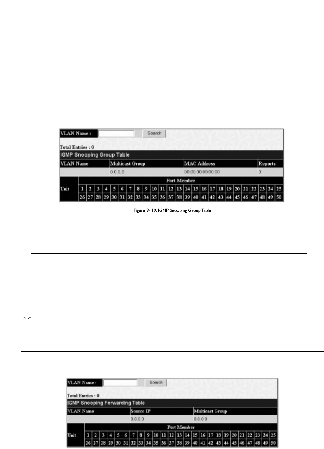
Parameter Description
Sequence A counter incremented whenever an entry to the Switch's history log is made.The table displays the last entry
(highest sequence number) first.
Time Displays the time in days, hours, and minutes since the Switch was last restarted.
Log Text Displays text describing the event that triggered the history log entry.
9-8 IGMP Snooping Group
This window allows the Switch’s IGMP Snooping Table to be viewed. IGMP Snooping allows the Switch to read the Multicast Group IP address and the
corresponding MAC address from IGMP packets that pass through the Switch.The number of IGMP reports that were snooped is displayed in the Reports
field.
To view the IGMP Snooping table, click IGMP Snooping Group on the Monitoring menu:
Figure 9- 19. IGMP Snooping Group Table
The user may search the IGMP Snooping Table by VLAN Name by entering it in the top left hand corner and clicking Search.
The following field can be viewed:
Parameter Description
VLAN Name The VLAN Name of the multicast group.
Multicast Group The IP address of the multicast group.
MAC Address The MAC address of the multicast group.
Reports The total number of reports received for this group.
Port Member These are the ports where the IGMP packets were snooped are displayed.
Note: To configure IGMP snooping for the AT-9724TS, go to the Configuration folder and select IGMP Snooping. Configuration and other
information concerning IGMP snooping may be found in Section 6 of this manual under IGMP.
9-9 IGMP Snooping Forwarding
This window will display the current IGMP snooping forwarding table entries currently configured on the Switch.To view the following screen, open the
Monitoring folder and click the IGMP Snooping Forwarding link.
Figure 9- 20. IGMP Snooping Forwarding Table
170
Allied Telesyn AT-9724TS High-Density Layer 3 Stackable Gigabit Ethernet Switch

The user may search the IGMP Snooping Forwarding Table by VLAN Name using the top left hand corner Search.
The following fields can be viewed:
Parameter Description
VLAN Name The VLAN Name of the multicast group.
Source IP The Source IP address of the multicast group.
Multicast Group The IP address of the multicast group.
Port Map These are the ports where the IP multicast packets are being forwarded to.
9-10 Browse Router Port
This displays which of the Switch’s ports are currently configured as router ports.A router port configured by a user (using the console or Web-based
management interfaces) is displayed as a static router port, designated by S.A router port that is dynamically configured by the Switch is designated by D.
Figure 9- 21. Browse Router Port window
9-11 Port Access Control
The following screens are used to monitor 802.1x statistics of the Switch, on a per port basis.To view the Port Access Control screens, open the monitoring
folder and click the Port Access Control folder.There are six screens to monitor.
Note: 802.1X must be enabled under Configuration > Advanced Settings.
Authenticator State
The following section describes the 802.1X Status on the Switch.To view the Authenticator State, click Monitoring > Port Access Control >
Authenticator State.
Figure 9- 22.Authenticator State window – Port Based 802.1x
171
Allied Telesyn AT-9724TS High-Density Layer 3 Stackable Gigabit Ethernet Switch

Figure 9- 23.Authenticator State – MAC Based 802.1X
This window displays the Authenticator State for individual ports on a selected device.To select unit within the switch stack, use the pull-down menu at the
top of the window and click Apply.A polling interval between 1and 60 seconds can be set using the drop-down menu at the top of the window and clicking
OK.
The information on this window is described as follows:
Parameter Description
Auth PAE State The Authenticator PAE State value can be: Initialize,Disconnected,Connecting,Authenticating,Authenticated,
Aborting,Held,Force_Auth,Force_Unauth,orN/A.N/A (Not Available) indicates that the port's authenticator
capability is disabled.
Backend State The Backend Authentication State can be Request,Response,Success,Fail,Timeout,Idle,Initialize,or N/A.
N/A (Not Available) indicates that the port's authenticator capability is disabled.
Port Status Controlled Port Status can be Authorized,Unauthorized, or N/A.
MAC Address Displays the MAC address of the Authenticator. Up to 16 MAC address can be implemented for MAC based
802.1x.
Authenticator Statistics
This table contains the statistics objects for the Authenticator PAE associated with each port.An entry appears in this table for each port that supports the
Authenticator function.To view the Authenticator Statistics, click Monitoring > Port Access Control > Authenticator Statistics.
172
Allied Telesyn AT-9724TS High-Density Layer 3 Stackable Gigabit Ethernet Switch
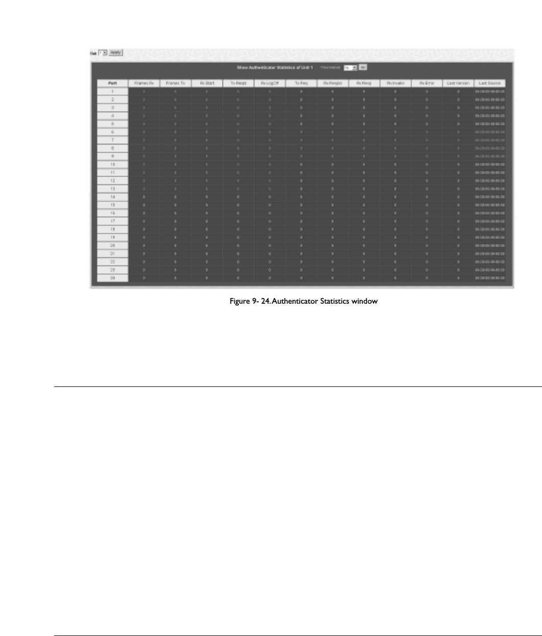
Figure 9- 24.Authenticator Statistics window
The user can specify a switch in a switch stack using that switch’s Unit ID by using the pull down menu in the top left hand corner.The user may also select the
desired time interval to update the statistics, between 1s and 60s, where “s” stands for seconds.The default value is one second.
The following fields can be viewed:
Parameter Description
Port The identification number assigned to the Port by the System in which the Port resides.
Frames Rx The number of valid EAPOL frames that have been received by this Authenticator.
Frames Tx The number of EAPOL frames that have been transmitted by this Authenticator.
Rx Start The number of EAPOL Start frames that have been received by this Authenticator.
TxReqId The number of EAP Req/Id frames that have been transmitted by this Authenticator.
RxLogOffThe number of EAPOL Logoff frames that have been received by this Authenticator.
Tx Req The number of EAP Request frames (other than Rq/Id frames) that have been transmitted by this
Authenticator.
Rx RespId The number of EAP Resp/Id frames that have been received by this Authenticator.
Rx Resp The number of valid EAP Response frames (other than Resp/Id frames) that have been received by this
Authenticator.
Rx Invalid The number of EAPOL frames that have been received by this Authenticator in which the frame type is not
recognized.
Rx Error The number of EAPOL frames that have been received by this Authenticator in which the Packet Body Length
field is invalid.
Last Version The protocol version number carried in the most recently received EAPOL frame.
Last Source The source MAC address carried in the most recently received EAPOL frame.
173
Allied Telesyn AT-9724TS High-Density Layer 3 Stackable Gigabit Ethernet Switch

Authenticator Session Statistics
This table contains the session statistics objects for the Authenticator PAE associated with each port.An entry appears in this table for each port that supports
the Authenticator function.To view the Authenticator Session Statistics,click Monitoring > Port Access Control > Authenticator Session
Statistics.
Figure 9- 25.Authenticator Session Statistics window
The user can specify a switch in a switch stack using that switch’s Unit ID by using the pull down menu in the top left hand corner.The user may also select the
desired time interval to update the statistics, between 1s and 60s,where “s” stands for seconds.The default value is one second.
The following fields can be viewed:
Parameter Description
Port The identification number assigned to the Port by the System in which the Port resides.
Octets Rx The number of octets received in user data frames on this port during the session.
Octets Tx The number of octets transmitted in user data frames on this port during the session.
Frames Rx The number of user data frames received on this port during the session.
Frames Tx The number of user data frames transmitted on this port during the session.
ID A unique identifier for the session, in the form of a printable ASCII string of at least three characters.
Authentic Method The authentication method used to establish the session.Valid Authentic Methods include:
Remote Authentic Server – The Authentication Server is external to the Authenticator’s System.
Local Authentic Server – The Authentication Server is located within the Authenticator’s System.
Time The duration of the session in seconds.
Terminate Cause The reason for the session termination.There are eight possible reasons for termination.
1. Supplicant Logoff
2. Port Failure
3. Supplicant Restart
4. Reauthentication Failure
5. AuthControlledPortControl set to ForceUnauthorized
6. Port re-initialization
7. Port Administratively Disabled
8. Not Terminated Yet
UserName The User-Name representing the identity of the Supplicant PAE.
174
Allied Telesyn AT-9724TS High-Density Layer 3 Stackable Gigabit Ethernet Switch

Authenticator Diagnostics
This table contains the diagnostic information regarding the operation of the Authenticator associated with each port.An entry appears in this table for each
port that supports the Authenticator function.To view the Authenticator Diagnostics,click Monitoring > Port Access Control > Authenticator
Diagnostics.
Figure 9- 26.Authenticator Diagnostics window
The user can specify a switch in a switch stack using that switch’s Unit ID by using the pull down menu in the top left hand corner.The user may also select the
desired time interval to update the statistics, between 1s and 60s, where “s” stands for seconds.The default value is one second.
The following fields can be viewed:
Parameter Description
PortThe identification number assigned to the Port by the System in which the Port resides.
Connect Enter Counts the number of times that the state machine transitions to the CONNECTING state from any other
state.
Connect LogOff Counts the number of times that the state machine transitions from CONNECTING to DISCONNECTED as
a result of receiving an EAPOL-Logoff message.
Auth Enter Counts the number of times that the state machine transitions from CONNECTING to AUTHENTICATING,
as a result of an EAP-Response/Identity message being received from the Supplicant.
Auth Success Counts the number of times that the state machine transitions from AUTHENTICATING to
AUTHENTICATED, as a result of the Backend Authentication state machine indicating successful authentication
of the Supplicant (authSuccess =TRUE).
Auth Timeout Counts the number of times that the state machine transitions from AUTHENTICATING to ABORTING, as a
result of the Backend Authentication state machine indicating authentication timeout (authTimeout = TRUE).
Auth Fail Counts the number of times that the state machine transitions from AUTHENTICATING to HELD, as a result
of the Backend Authentication state machine indicating authentication failure (authFail = TRUE).
Auth Reauth Counts the number of times that the state machine transitions from AUTHENTICATING to ABORTING, as a
result of a reauthentication request (reAuthenticate = TRUE).
Auth Start Counts the number of times that the state machine transitions from AUTHENTICATING to ABORTING, as a
result of an EAPOL-Start message being received from the Supplicant.
Auth LogOff Counts the number of times that the state machine transitions from AUTHENTICATING to ABORTING, as a
result of an EAPOL-Logoff message being received from the Supplicant.
Authed Reauth Counts the number of times that the state machine transitions from AUTHENTICATED to CONNECTING, as
a result of a reauthentication request (reAuthenticate = TRUE).
175
Allied Telesyn AT-9724TS High-Density Layer 3 Stackable Gigabit Ethernet Switch

Authed Start Counts the number of times that the state machine transitions from AUTHENTICATED to CONNECTING, as
a result of an EAPOL-Start message being received from the Supplicant.
Authed LogOff Counts the number of times that the state machine transitions from AUTHENTICATED to DISCONNECTED,
as a result of an EAPOL-Logoff message being received from the Supplicant.
Responses Counts the number of times that the state machine sends an initial Access-Request packet to the
Authentication server (i.e., executes sendRespToServer on entry to the RESPONSE state). Indicates that the
Authenticator attempted communication with the Authentication Server.
AccessChallenges Counts the number of times that the state machine receives an initial Access-Challenge packet from the
Authentication server (i.e., aReq becomes TRUE, causing exit from the RESPONSE state). Indicates that the
Authentication Server has communication with the Authenticator.
OtherReqToSupp Counts the number of times that the state machine sends an EAP-Request packet (other than an Identity,
Notification, Failure, or Success message) to the Supplicant (i.e., executes txReq on entry to the REQUEST
state). Indicates that the Authenticator chose an EAP-method.
NonNakRespFromSup Counts the number of times that the state machine receives a response from the Supplicant to an initial EAP-
Request, and the response is something other than EAP-NAK (i.e., rxResp becomes TRUE, causing the state
machine to transition from REQUEST to RESPONSE, and the response is not an EAP-NAK). Indicates that the
Supplicant can respond to the Authenticator’s chosen EAP-method.
Bac Auth Success Counts the number of times that the state machine receives an Accept message from the Authentication Server
(i.e., aSuccess becomes TRUE, causing a transition from RESPONSE to SUCCESS). Indicates that the Supplicant
has successfully authenticated to the Authentication Server.
Bac Auth Fail Counts the number of times that the state machine receives a Reject message from the Authentication Server
(i.e., aFail becomes TRUE, causing a transition from RESPONSE to FAIL). Indicates that the Supplicant has not
authenticated to the Authentication Server.
RADIUS Authentication
This table contains information concerning the activity of the RADIUS authentication client on the client side of the RADIUS authentication protocol. It has one
row for each RADIUS authentication server that the client shares a secret with.To view the RADIUS Authentication, click Monitoring > Port Access
Control > RADIUS Authentication.
Figure 9- 27. RADIUS Authentication window
The user may also select the desired time interval to update the statistics, between 1s and 60s, where “s” stands for seconds.The default value is one second.To
clear the current statistics shown, click the Clear button in the top left hand corner.
The following fields can be viewed:
Parameter Description
ServerIndex The identification number assigned to each RADIUS Authentication server that the client shares a secret with.
InvalidServerAddr The number of RADIUS Access-Response packets received from unknown addresses.
Identifier The NAS-Identifier of the RADIUS authentication client. (This is not necessarily the same as sysName in MIB
II.)
AuthServerAddr The (conceptual) table listing the RADIUS authentication servers with which the client shares a secret.
ServerPortNumber The UDP port the client is using to send requests to this server.
RoundTripTime The time interval (in hundredths of a second) between the most recent Access-Reply/Access-Challenge and the
Access-Request that matched it from this RADIUS authentication server.
AccessRequests The number of RADIUS Access-Request packets sent to this server.This does not include retransmissions.
AccessRetrans The number of RADIUS Access-Request packets retransmitted to this RADIUS authentication server.
AccessAccepts The number of RADIUS Access-Accept packets (valid or invalid) received from this server.
AccessRejects The number of RADIUS Access-Reject packets (valid or invalid) received from this server.
AccessChallenges The number of RADIUS Access-Challenge packets (valid or invalid) received from this server.
AccessResponses The number of malformed RADIUS Access-Response packets received from this server. Malformed packets
include packets with an invalid length. Bad authenticators or Signature attributes or known types are not
included as malformed access responses.
176
Allied Telesyn AT-9724TS High-Density Layer 3 Stackable Gigabit Ethernet Switch

Note: To configure 802.1x features for the AT-9724TS, go to the Configuration folder and select Port Access Entity. Configuration
and other information concerning 802.1x may be found in Section 6 of this manual under Port Access Entity.
9-12 Layer 3 Feature
This folder in the Monitoring section will display information concerning settings configured in Layer 3 IP Networking of the Configuration folder.
These settings and parameters have been previously described in Chapter 6 of this manual, under Layer 3 IP Networking.
Browse IP Address
The Browse IP Address window may be found in the Monitoring menu in the Layer 3 Feature folder.The Browse IP Address window is a read
only screen where the user may view IP addresses discovered by the Switch.To search a specific IP address, enter it into the field labelled IP Address at the top
of the screen and click Find to begin your search.
Figure 9- 29. Browse IP Address Table
178
Allied Telesyn AT-9724TS High-Density Layer 3 Stackable Gigabit Ethernet Switch

Browse Routing Table
The Browse Routing Table window may be found in the Monitoring menu in the Layer 3 Feature folder.This screen shows the current IP routing
table of the Switch.To find a specific IP route, enter an IP address into the Destination Address field along with a proper subnet mask into the Mask field
and click Find.
Figure 9- 30. Browse Routing Table window
Browse ARP Table
The Browse ARP Table window may be found in the Monitoring menu in the Layer 3 Feature folder.This window will show current ARP entries on
the Switch.To search a specific ARP entry, enter an interface name into the Interface Name or an IP address and click Find.To clear the ARP Table, click
Clear All.
Figure 9- 31. Browse ARP Table window
Browse IP Multicast Forwarding Table
The Browse IP Multicast Forwarding Table window may be found in the Monitoring menu in the Layer 3 Feature folder.This window will show
current IP multicasting information on the Switch.To search a specific entry, enter an multicast group IP address into the Multicast Group field or a Source
IP address and click Find.
179
Allied Telesyn AT-9724TS High-Density Layer 3 Stackable Gigabit Ethernet Switch

Figure 9- 32. Browse IP Multicast Forwarding Table
Browse IGMP Group Table
The Browse IGMP Group Table window may be found in the Monitoring menu in the Layer 3 Feature folder.This window will show current IGMP
group entries on the Switch.To search a specific IGMP group entry, enter an interface name into the Interface Name field or a Multicast Group IP
address and click Find.
Figure 9- 33. Browse IGMP Group Table
OSPF Monitoring
This section offers windows regarding OSPF (Open Shortest Path First) information on the Switch, including the OSPF LSDB Table,OSPF Neighbor
Table and the OSPF Virtual Neighbor Table.To view these tables, open the Monitoring folder and click OSPF Monitoring.
Browse OSPF LSDB Table
This table can be found in the OSPF Monitoring folder by clicking on the Browse OSPF LSDB Table link.The OSPF Link-State Database Table
displays the current link-state database in use by the OSPF routing protocol on a per-OSPF area basis.
Figure 9- 34. Browse OSPF LSDB Table
The user may search for a specific entry by entering the following information into the fields at the top of the screen:
To browse the OSPF LSDB Table, you first must select which browse method you want to use in the Search Type field.The choices are All,Area ID,
Advertise Router ID,LSDB,Area ID & Advertise Router ID,Area ID & LSDB,and Advertise Router ID & LSDB.
If Area ID is selected as the browse method, you must enter the IP address in the Area ID field, and then click Find.
If Adv. Router ID is selected, you must enter the IP address in the Advertisement Router ID field, and then click Find.
If LSDB is selected, you must select the type of link state (RtrLink,NetLink,Summary,ASSummaryand ASExtLink) in the LSDB Type field, and then click Find.
180
Allied Telesyn AT-9724TS High-Density Layer 3 Stackable Gigabit Ethernet Switch
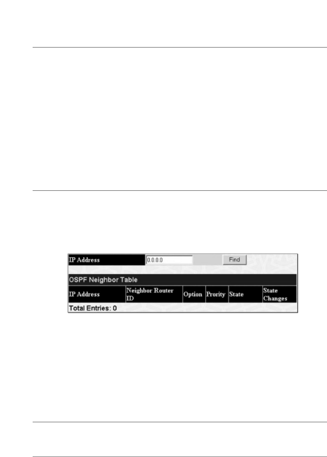
The following fields are displayed in the OSPF LSDB Table:
Parameter Description
Area ID Allows the entry of an OSPF Area ID.This Area ID will then be used to search the table, and display an entry –
if there is one.
LSDB Type Displays which one of eight types of link advertisements by which the current link was discovered by the
Switch: All, Router link (RTRLink), Network link (NETLink), Summary link (Summary),Autonomous System link
(ASSummary),Autonomous System external link (ASExternal), MCGLink (Multicast Group), and NSSA (Not So
Stubby Area)
Adv. Router ID Displays the Advertising Router’s ID.
Link State ID This field identifies the portion of the Internet environment that is being described by the advertisement.
The contents of this field depend on the advertisement's LS type.
LS Type LinkState ID
1 The originating router's Router ID.
2 The IP interface address of the network's Designated Router.
3 The destination network's IP address.
4The Router ID of the described AS boundary router.
Cost Displays the cost of the table entry.
Sequence Displays a sequence number corresponding to number of times the current link has been advertised as
changed.
Browse OSPF Neighbor Table
This table can be found in the OSPF Monitoring folder by clicking on the Browse OSPF Neighbor Table link. Routers that are connected to the same
area or segment become neighbors in that area. Neighbors are elected via the Hello protocol. IP multicast is used to send out Hello packets to other routers on
the segment. Routers become neighbors when they see themselves listed in a Hello packet sent by another router on the same segment. In this way, two-way
communication is guaranteed to be possible between any two neighbor routers.This table displays OSPF neighbors of the Switch.
Figure 9- 35. OSPF Neighbor Table
To search for OSPF neighbors, enter an IP address and click Find.Valid OSPF neighbors will appear in the OSPF Neighbor Table below.
OSPF Virtual Neighbor
This table can be found in the OSPF Monitoring folder by clicking on the Browse OSPF Virtual Neighbor link.This table displays a list of Virtual
OSPF Neighbors of the Switch.The user may choose specifically search a virtual neighbor by using one of the two search options at the top of the screen,
which are:
Parameter Description
Transit Area ID Allows the entry of an OSPF Area ID – previously defined on the Switch – that allows a remote area to
communicate with the backbone (area 0).A Transit Area cannot be a Stub Area or a Backbone Area.
Neighbor ID The OSPF router ID for the remote router.This IP address uniquely identifies the remote area’s Area Border
Router.
181
Allied Telesyn AT-9724TS High-Density Layer 3 Stackable Gigabit Ethernet Switch

Figure 9- 36 .OSPF Virtual Neighbor Table
DVMRP Monitoring
This menu allows the DVMRP (Distance-Vector Multicast Routing Protocol) to be monitored for each IP interface defined on the Switch.This folder, found in
the Monitoring folder, offers 3 screens for monitoring; Browse DVMRP Routing Table,Browse DVMRP Neighbor Address Table and Browse
DVMRP Routing Next Hop Table. Information on DVMRP and its features in relation to the AT-9724TS can be found in Chapter 6, under IP Multicast
Routing Protocol.
Browse DVMRP Routing Table
Multicast routing information is gathered and stored by DVMRP in the DVMRP Routing Table, which may be found in the Monitoring folder under
Browse DVMRP Monitoring, contains one row for each port in a DVMRP mode. Each routing entry contains information about the source and multicast
group, and incoming and outgoing interfaces.You may define your search by entering a Source IP Address and its subnet mask into the fields at the top of the
page.
Figure 9- 37 . DVMRP Routing Table
Browse DVMRP Neighbor Address Table
This table, found in the Monitoring menu under DVMRP Monitor > Browse DVMRP Neighbor Address Table contains information about
DVMRP neighbors of the Switch.To search this table, enter either an Interface Name or Neighbor Address into the respective field and click the Find
button. DVMRP neighbors of that entry will appear in the DVMRP Neighbor Table below.
Figure 9- 38. DVMRP Neighbor Table
182
Allied Telesyn AT-9724TS High-Density Layer 3 Stackable Gigabit Ethernet Switch

Browse DVMRP Routing Next Hop Table
The DVMRP Routing Next Hop Table contains information regarding the next-hop for forwarding multicast packets on outgoing interfaces. Each entry in
the DVMRP Routing Next Hop Table refers to the next-hop of a specific source to a specific multicast group address.This table is found in the
Monitoring menu under DVMRP Monitoring, with the heading Browse DVMRP Routing Next Hop Table.To search this table, enter either an
Interface Name or Source IP Address into the respective field and click the Find button.The next hop of that DVMRP Routing entry will appear in the
DVMRP Routing Next Hop Table below.
Figure 9- 39. DVMRP Routing Next Hop Table
PIM Monitoring
Multicast routers use Protocol Independent Multicast (PIM) to determine which other multicast routers should receive multicast packets.To find out
more information concerning PIM and its configuration on the Switch, see the IP Multicasting chapter of Chapter 6, Configuration.
PIM Neighbor Address Table
The PIM Neighbor Address Table contains information regarding each of a router’s PIM neighbors.This screen may be found in the Monitoring folder
under the heading PIM Monitor.To search this table, enter either an Interface Name or Neighbor Address into the respective field and click the Find
button. PIM neighbors of that entry will appear in the PIM Neighbor Table below.
Figure 9- 40. PIM Neighbor Table
183
Allied Telesyn AT-9724TS High-Density Layer 3 Stackable Gigabit Ethernet Switch

Chapter 10 - Switch Maintenance
10-1 TFTP Services
10-2 Multiple Image Services
10-3 CF Services
10-4 Ping Test
10-5 Save Changes
10-6 Reset
10-7 Reboot Services
10-8 Logout
10-1 TFTP Service
Trivial File Transfer Protocol (TFTP) services allow the Switch’s firmware to be upgraded by transferring a new firmware file from a TFTP server to the
Switch.A configuration file can also be loaded into the Switch from a TFTP server, switch settings can be saved to the TFTP server, and a history log can be
uploaded from the Switch to the TFTP server.
Download Firmware
To update the Switch’s firmware, open the TFTP Services folder in the Maintenance folder and then click the Download Firmware link:
Figure 10- 1. Download Firmware window
Unit ID – Select which switch of a switch stack you want to update the firmware on.This allows the selection of a particular switch from a switch stack if you
have installed the optional stacking module and have properly interconnected the switches. All indicates all switches in a switch stack will download the same
firmware.
Enter the IP address of the TFTP server in the Server IP Address field.
Select the Image ID of the firmware.The AT-9724TS can hold two firmware images in its memory. Image ID 1 will always be the boot up firmware for the Switch
unless specified by the user. Information on configuring Image IDs can be found in this section, under the heading MULTIPLE IMAGE Services.
The TFTP server must be on the same IP subnet as the Switch.
Enter the path and the filename to the firmware file on the TFTP server. Note that in the above example, the firmware file is in the root directory of the D drive
of the TFTP server.
The TFTP server must be running TFTP server software to perform the file transfer.TFTP server software is a part of many network management software
packages – such as NetSight, or can be obtained as a separate program.
Click Start to record the IP address of the TFTP server and begin the file transfer.
Download Configuration File
T
o download a configuration file from a TFTP server, click on the TFTP Service folder in the Maintenance folder and then the Download
Configuration File link:
Figure 10- 2. Download Configuration File window
184
Allied Telesyn AT-9724TS High-Density Layer 3 Stackable Gigabit Ethernet Switch

Enter the IP address of the TFTP server and specify the location of the switch configuration file on the TFTP server.
Click Start to initiate the file transfer.
Upload Configuration
To upload the Switch’s settings to a TFTP server, click on the TFTP Service folder in the Maintenance folder and then click the Save Settings link:
Figure 10- 3. Upload Configuration window
Enter the IP address of the TFTP server and the path and filename for the configuration file on the TFTP server.
Click Start to initiate the file transfer.
Upload Log
To upload the Switch history log file to a TFTP server, open the TFTP Service folder in the Maintenance folder and then click the Upload Log link:
Figure 10- 4. Upload Log window
Enter the IP address of the TFTP server and the path and filename for the history log on the TFTP server.
Click Start to record the IP address of the TFTP server and to initiate the file transfer.
10-2 Multiple Image Services
The Multiple Image Services folder allow users of the AT-9724TS to configure and view information regarding firmware located on the Switch.The Switch
allows two firmware images to be stored in its memory and either can be configured to be the boot up firmware for the Switch. For information regarding
firmware images located on the Switch, open the Firmware Information link.The default setting for the Switch’s firmware will have the boot up firmware
stored in Image 1, but the user may set either firmware stored to be the boot up firmware by using the Config Firmware Image window.
Firmware Information
The following screen allows the user to view information about current firmware images stored on the Switch.To access the following screen, click
Maintenance > MULTIPLE IMAGE Services > Firmware Information.
185
Allied Telesyn AT-9724TS High-Density Layer 3 Stackable Gigabit Ethernet Switch

Figure 10- 5. Firmware Information window
This window holds the following information:
Parameter Description
BOX States the stacking ID number of the switch in the switch stack.
ID States the image ID number of the firmware in the Switch’s memory.The Switch can store 2 firmware images
for use. Image ID 1 will be the default boot up firmware for the Switch unless otherwise configured by the user.
Version States the firmware version.
Size States the size of the corresponding firmware, in bytes.
Update Time States the specific time the firmware version was downloaded to the Switch.
From States the IP address of the origin of the firmware.There are four ways firmware may be downloaded to the
Switch.
R– If the IP address has this letter attached to it, it denotes a firmware upgrade through the Console Serial
Port (RS-232).
T– If the IP address has this letter attached to it, it denotes a firmware upgrade through Telnet.
S– If the IP address has this letter attached to it, it denotes a firmware upgrade through the Simple Network
Management Protocol (SNMP).
W – If the IP address has this letter attached to it, it denotes a firmware upgrade through the web-based
management interface.
User States the user who downloaded the firmware.This field may read “Anonymous” or “Unknown” for users that
are not identified.
Config Firmware Image
The Config Firmware Image window allows users to configure firmware images saved in the memory of the Switch.To access the following window, click
Maintenance > MULTIPLE IMAGE Services > Config Firmware Image.
Figure 10- 6. Config Firmware Image window
186
Allied Telesyn AT-9724TS High-Density Layer 3 Stackable Gigabit Ethernet Switch
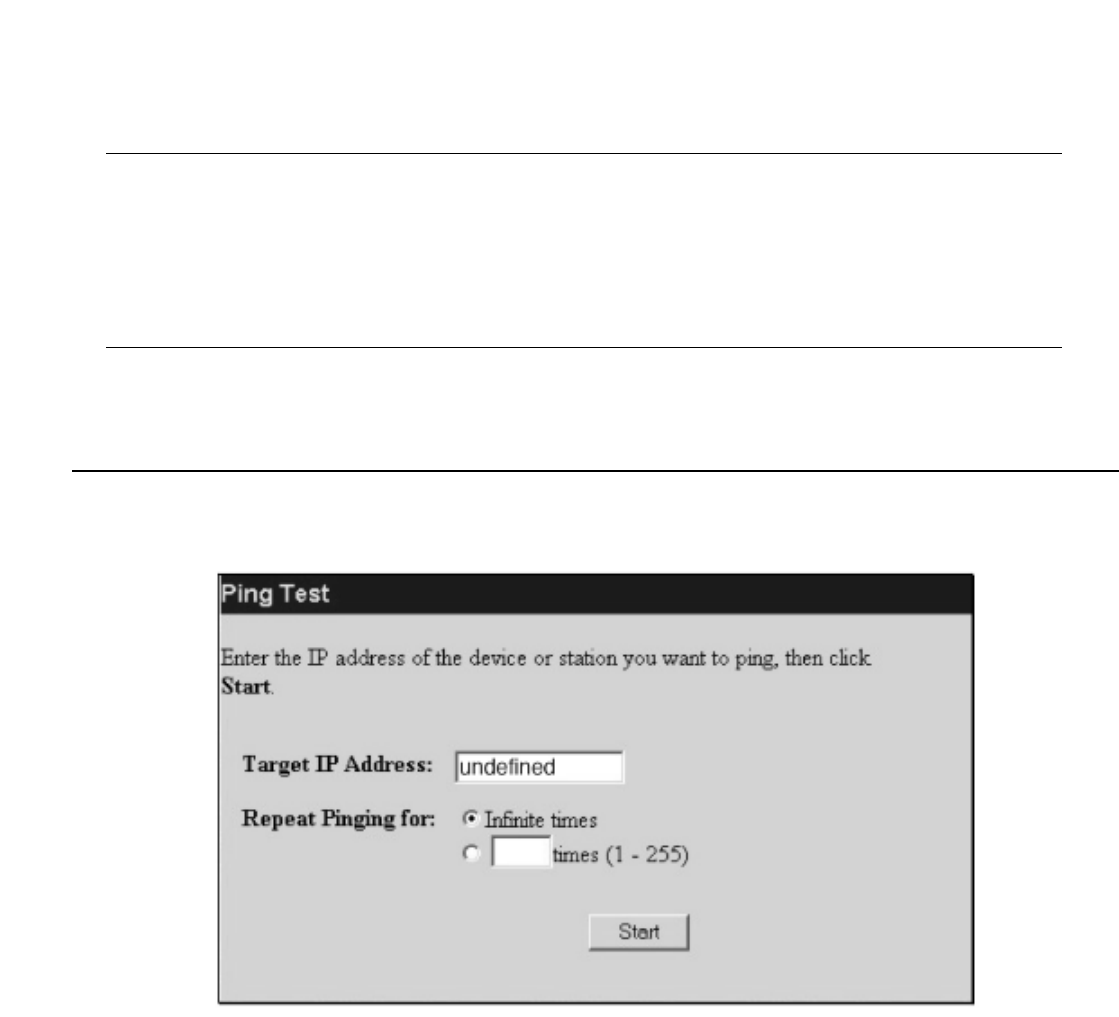
This window offers the following information:
Parameter Description
Image Select the firmware image to be configured using the pull-down menu.The Switch allows two firmware images
to be stored in the Switch’s memory.
Active This field has two options for configuration.
Delete – Select this option to delete the firmware image specified in the Image field above.
Boot – Select this option to set the firmware image specified above as the boot up firmware for the Switch.This
firmware will be set as the boot up firmware after a switch reboot has been performed.The default setting has
firmware image ID 1 as the boot up firmware image for the Switch unless specified here.
Click Apply to implement changes made.
10-4 Ping Test
Ping is a small program that sends ICMP Echo packets to the IP address you specify.The destination node then responds to or "echoes" the packets sent from the
Switch.This is very useful to verify connectivity between the Switch and other nodes on the network.
Figure 10- 7. Ping Test
The user may use Infinite times radio button, in the Repeat Pinging for: field, which will tell the ping program to keep sending ICMP Echo packets to the
specified IP address until the program is stopped.The user may opt to choose a specific number of times to ping the Target IP Address by clicking its radio
button and entering a number between 1 and 255.
Click Start to initiate the Ping program.
187
Allied Telesyn AT-9724TS High-Density Layer 3 Stackable Gigabit Ethernet Switch

10-5 Save Changes
The AT-9724TS has two levels of memory; normal RAM and non-volatile or NV-RAM. Configuration changes are made effective clicking the Apply button.When
this is done, the settings will be immediately applied to the switching software in RAM, and will immediately take effect.
Some settings, though, require you to restart the Switch before they will take effect. Restarting the Switch erases all settings in RAM and reloads the stored
settings from the NV-RAM.Thus, it is necessary to save all setting changes to NV-RAM before rebooting the switch.
To retain any configuration changes permanently, click on the Save button in the Save Changes page, as shown below.
Figure 10- 8. Save Changes Screen
The Switch has three levels of save, which are as follows:
Parameter Description
Save (Only save config) Clicking the radio button for this entry will save only the current switch configuration to NV-RAM.
Save Log (Only save log) Clicking the radio button for this entry will save only the current current log file to NV- RAM.
Save All (Save config and log) Clicking the radio button for this entry will save both the current switch configuration and the current log file
to NV-RAM.
These settings will be used every time the Switch is rebooted. See the Reset section for more information on changing configurations saved to NV-RAM.
10-6 Reset
The Reset function has several options when resetting the Switch. Some of the current configuration parameters can be retained while resetting all other
configuration parameters to their factory defaults.
Note:Only the Reset System option will enter the factory default parameters into the Switch’s non-volatile RAM, and then restart the Switch.
All other options enter the factory defaults into the current configuration, but do not save this configuration. Reset System will return the Switch’s
configuration to the state it was when it left the factory.
Figure 10- 9. Factory Reset to Default Value window
188
Allied Telesyn AT-9724TS High-Density Layer 3 Stackable Gigabit Ethernet Switch

10-7 Reboot Device
The following menu is used to restart the Switch.
Figure 10- 10. Restart System window
Clicking the Yes click-box will instruct the Switch to save the current configuration to non-volatile RAM before restarting the Switch.
Clicking the No click-box instructs the Switch not to save the current configuration before restarting the Switch.All of the configuration information entered
from the last time Save Changes was executed, will be lost.
Click the Restart button to restart the Switch.
10-8 Logout
Use the Logout page to logout of the Switch’s Web-based management agent by clicking on the Log Out button.
Figure 10- 11 . Logout window
189
Allied Telesyn AT-9724TS High-Density Layer 3 Stackable Gigabit Ethernet Switch

Appendix A - Technical Specifications
General
Standard IEEE 802.3u 100TX Fast Ethernet
IEEE 802.3ab 1000T Gigabit Ethernet
IEEE 802.1 P/Q VLAN
IEEE 802.3x Full-duplex Flow Control
IEEE 802.3 Nway auto-negotiation
Protocols CSMA/CD
Data Transfer Rates: Half-duplex Full-duplex
Ethernet 10Mbps 20Mbps
Fast Ethernet 100Mbps 200Mbps
Gigabit Ethernet 1000Mbps 2000Mbps
Fibre Optic IEC 793-2: 1992
Type A1a - 50/125um multi-mode
Type A1b - 62.5/125um multi-mode
Both types use LC optical connector
Topology Ring
Network Cables UTP Cat.5 for 100Mbps
UTP Cat.3, 4, 5 for 10Mbps
EIA/TIA-568 100-ohm screened twisted-pair (STP)(100m)
Physical & Environmental
AC inputs & External
Redundant Power Supply 100 – 240
VAC, 50/60 Hz (internal universal power supply)
Power Consumption: 90 watts maximum
DC fans: 2 built-in 40 x 40 x 10 mm fans; 1 built-in 60 x 60 x 18 mm fan
Operating Temperature: 0 to 40 degrees C
Storage Temperature: -25 to 55 degrees C
Humidity: Operating: 5% to 95% RH non-condensing
Storage: 0% to 95% RH non-condensing
Dimensions: 441 mm x 207 mm x 44 mm (1U), 19 inch rackmount width
Weight: 3.15 kg
EMC: FCC Part 15 Class A/ ICES-003 Class (Canada)
EN55022 Class A / EN55024
Safety: CSA International
190
Allied Telesyn AT-9724TS High-Density Layer 3 Stackable Gigabit Ethernet Switch

Performance
Transmission Method: Store-and-forward
RAM Buffer: 2 MB per device
Filtering Address Table: 16 K MAC address per device
Packet Filtering/ Full-wire speed for all connections.
Forwarding Rate: 148,810 pps per port (for 100Mbps)
1,488,100 pps per port (for 1000Mbps)
MAC Address Learning: Automatic update.
Forwarding Table Age Time: Max age: 10 – 1000000 seconds.
Default = 300.
191
Allied Telesyn AT-9724TS High-Density Layer 3 Stackable Gigabit Ethernet Switch
Produkt Specifikationer
| Mærke: | Allied Telesis |
| Kategori: | Diverse - Andet |
| Model: | AT-9724TS |
Har du brug for hjælp?
Hvis du har brug for hjælp til Allied Telesis AT-9724TS stil et spørgsmål nedenfor, og andre brugere vil svare dig
Diverse - Andet Allied Telesis Manualer

6 Juli 2024
6 Juli 2024
5 Juli 2024
5 Juli 2024
4 Juli 2024
4 Juli 2024
28 Juni 2024
Diverse - Andet Manualer
- Diverse - Andet Samsung
- Diverse - Andet Gigaset
- Diverse - Andet Apple
- Diverse - Andet Logitech
- Diverse - Andet Epson
- Diverse - Andet HP
- Diverse - Andet D-Link
- Diverse - Andet Roland
- Diverse - Andet Casio
- Diverse - Andet TRENDnet
- Diverse - Andet Trust
- Diverse - Andet Linksys
- Diverse - Andet Gembird
- Diverse - Andet NewStar
- Diverse - Andet EnVivo
- Diverse - Andet Mad Catz
- Diverse - Andet Western Digital
- Diverse - Andet Digitus
- Diverse - Andet APC
- Diverse - Andet LevelOne
- Diverse - Andet ZyXEL
- Diverse - Andet TrekStor
- Diverse - Andet Synology
- Diverse - Andet Albrecht
- Diverse - Andet Veho
- Diverse - Andet EnGenius
- Diverse - Andet Devolo
- Diverse - Andet Alesis
- Diverse - Andet AudioSonic
- Diverse - Andet Saitek
- Diverse - Andet DeLOCK
- Diverse - Andet Eminent
- Diverse - Andet Fantec
- Diverse - Andet Zagg
- Diverse - Andet Akasa
- Diverse - Andet Power Dynamics
- Diverse - Andet Sharkoon
- Diverse - Andet Draytek
- Diverse - Andet Lancom
- Diverse - Andet Sitecom
- Diverse - Andet Ketron
- Diverse - Andet Allnet
- Diverse - Andet Maxdata
- Diverse - Andet Genexis
- Diverse - Andet Ewent
- Diverse - Andet Storage Options
- Diverse - Andet SIM
- Diverse - Andet Griffin
- Diverse - Andet Franklin
- Diverse - Andet Ebode
- Diverse - Andet Online
- Diverse - Andet Minix
- Diverse - Andet ISY
- Diverse - Andet Solcon
- Diverse - Andet Telekom
- Diverse - Andet Soundlogic
- Diverse - Andet Konig Electronic
- Diverse - Andet Wyse - Dell
- Diverse - Andet Rion
Nyeste Diverse - Andet Manualer
14 Januar 2025
14 Januar 2025
5 Oktober 2024
25 September 2024
22 September 2024
18 September 2024
17 September 2024
16 September 2024
16 September 2024
27 August 2024