APC AP5615 Manual
Læs nedenfor 📖 manual på dansk for APC AP5615 (133 sider) i kategorien Skifte. Denne guide var nyttig for 15 personer og blev bedømt med 4.5 stjerner i gennemsnit af 2 brugere
Side 1/133

Installer/User Guide
Digital KVM Switches
AP5610, AP5615 and AP5616

USA Notification
Warning: Changes or modifications to this unit not expressly approved by the party responsible for
compliance could void the user’s authority to operate the equipment.
Note: This equipment has been tested and found to comply with the limits for a Class A digital device,
pursuant to Part 15 of the FCC Rules. These limits are designed to provide reasonable protection
against harmful interference when the equipment is operated in a commercial environment. This
equipment generates, uses and can radiate radio frequency energy and, if not installed and used in
accordance with the instruction manual, may cause harmful interference to radio communications.
Operation of this equipment is a residential area is likely to cause harmful interference, in which case the
user will be required to correct the interference at his/her own expense.
Canadian Notification
This Class A digital apparatus complies with Canadian ICES-003.
Cet appareil numérique de la classe A est conforme à la norme NMB-003 du Canada.
Japanese Notification
Korean Notification

APC® KVM Switch
Installer/User Guide
© 2008 American Power Conversion Corporation. All rights reserved.
APC and the APC logo are registered trademarks of American Power
Conversion Corporation or its affiliates. All other marks are the property
of their respective owners.
APC: 990-3256A
590-800-501C
Instructions
This symbol is intended to alert the user to the presence of important operating and maintenance instructions in
the literature accompanying the KVM switch.
Dangerous Voltage
This symbol is intended to alert the user to the presence of uninsulated dangerous voltage within the product’s
enclosure that may be of sufficient magnitude to constitute a risk of electric shock to persons.
Power On
This symbol indicates the principal on/off switch is in the on position.
Power Off
This symbol indicates the principal on/off switch is in the off position.
Protective Grounding Terminal
This symbol indicates a terminal which must be connected to earth ground prior to making any other
connections to the equipment.

iii
Table of Contents
List of Figures ................................................................................................................. ix
List of Tables.................................................................................................................... x
Chapter 1: Product Overview.......................................................................................... 1
Features And Benefits........................................................................................................................ 1
Intelligent cables......................................................................................................................... 1
Virtual Media.............................................................................................................................. 2
OSD graphical user interface..................................................................................................... 3
Video ........................................................................................................................................... 3
Flash upgradability .................................................................................................................... 3
Web interface .............................................................................................................................. 3
Authentication and authorization ............................................................................................... 3
Video Viewer............................................................................................................................... 4
Network Access Software............................................................................................................ 4
Modem ........................................................................................................................................ 5
Chapter 2: Installation ..................................................................................................... 6
Installing And Setting Up The KVM Switch.......................................................................................6
Connecting the KVM switch ....................................................................................................... 6
Connecting a KVM server module to each target device ........................................................... 7
Setting up the network ................................................................................................................ 7
Connecting local peripheral devices .......................................................................................... 8
Tiering Multiple KVM Switches......................................................................................................... 9
Installing And Starting Up The Web Interface ................................................................................ 10
Supported browsers .................................................................................................................. 10
Launching the web interface..................................................................................................... 10
Installing And Starting Up The Network Access Software .............................................................. 11
Supported operating systems .................................................................................................... 11
Hardware configuration requirements ..................................................................................... 11
Browser requirements............................................................................................................... 11
Installing the software .............................................................................................................. 11
Uninstalling the software.......................................................................................................... 13
TABLE OF CONTE NTS

Table of Contents iv
Opening the software ................................................................................................................ 13
Setting up the software ............................................................................................................. 14
Rack Mounting A KVM Switch ........................................................................................................ 14
Rack mount safety considerations ............................................................................................ 14
Installing a rack mounting bracket........................................................................................... 15
Chapter 3: Basic Operations......................................................................................... 16
Controlling The Switching System From The Analog Port ............................................................. 16
Starting The OSD............................................................................................................................. 16
Connecting A User To A Target Device .......................................................................................... 17
Using The OSD ................................................................................................................................ 18
Configuring The KVM Switch And The OSD................................................................................... 19
Assigning target device names.................................................................................................. 20
Assigning device types .............................................................................................................. 21
Changing the display behavior ................................................................................................. 21
Selecting display language ....................................................................................................... 22
Controlling the status flag ........................................................................................................22
Setting the keyboard country code............................................................................................ 23
Setting KVM switch security..................................................................................................... 24
Setting The Preemption Warning.....................................................................................................25
Managing Target Device Tasks Using The OSD............................................................................. 26
Displaying version information ................................................................................................ 26
Upgrading the firmware ........................................................................................................... 27
Viewing the display configuration ............................................................................................27
Viewing and disconnecting user connections ........................................................................... 27
Resetting the keyboard and mouse ........................................................................................... 27
Power Controlling Devices..............................................................................................................28
Power window ..........................................................................................................................28
PDUs window........................................................................................................................... 29
PDU Settings window............................................................................................................... 29
PDU Inlets window................................................................................................................... 30
PDU Outlets window ................................................................................................................ 30
Scanning The Switching System.......................................................................................................31
Running Switching System Diagnostics ........................................................................................... 32
Broadcasting To Target Devices ..................................................................................................... 33

Table of Contents v
Chapter 4: Network Access Software .......................................................................... 35
Window Features ............................................................................................................................. 35
Customizing the window display .............................................................................................. 37
Adding A KVM Switch ..................................................................................................................... 37
Accessing KVM Switches .................................................................................................................40
Accessing Target Devices ................................................................................................................ 40
Accessing CPS target devices...................................................................................................42
Launching The VNC Or RDP Viewer .............................................................................................. 44
Customizing Properties.................................................................................................................... 44
General properties.................................................................................................................... 44
Viewing and changing network properties for a KVM switch.................................................. 45
Viewing and changing network properties for a target device.................................................45
Information properties..............................................................................................................45
Connections properties.............................................................................................................46
VNC Properties.........................................................................................................................46
RDP Properties.........................................................................................................................47
Telnet properties.......................................................................................................................48
Customizing Options........................................................................................................................ 49
Viewing and changing general options ....................................................................................49
HTTP/HTTPS options...............................................................................................................51
VNC options..............................................................................................................................52
RDP options..............................................................................................................................52
Telnet options ........................................................................................................................... 53
Managing Folders............................................................................................................................ 54
Assigning Units ................................................................................................................................ 54
Deleting Units .................................................................................................................................. 55
Renaming Units................................................................................................................................56
Target device naming ............................................................................................................... 57
Managing The Software Database .................................................................................................. 58
Saving and loading a database................................................................................................. 58
Exporting a database................................................................................................................ 58
Chapter 5: Web Interface............................................................................................... 60
Accessing Servers From The Web Interface .................................................................................... 60
Viewing and Configuring KVM Switch Settings .............................................................................. 60

Table of Contents viii
Appendix C: Keyboard And Mouse Shortcuts ............................................................................... 109
Appendix D: Sun Advanced Key Emulation .................................................................................. 111
Appendix E: Ports Used By The Software ..................................................................................... 113
Appendix F: Product Specification................................................................................................114
Appendix G: Getting Help And Technical Assistance ................................................................... 118
Appendix H: Notices ...................................................................................................................... 119

ix
List of Figures
Figure 1.1: Examples of KVM server modules.................................................................................. 2
Figure 1.2: Example KVM switch configuration...............................................................................4
Figure 2.1: KVM switch configuration example ...............................................................................8
Figure 2.2: KVM switch configuration with a tiered KVM switch .................................................... 9
Figure 4.1: Network Access Software window ................................................................................36
Figure 6.1: Video Viewer window ................................................................................................... 85
Figure 6.2: Manual Video Adjust window ...................................................................................... 87
L I S T O F F I G U R E S

x
List of Tables
Table 3.1: OSD interface status symbols......................................................................................... 17
Table 3.2: OSD interface navigation basics.................................................................................... 18
Table 3.3: Setup features to manage routine tasks for the target devices ....................................... 20
Table 3.4: OSD interface status flags.............................................................................................. 23
Table 3.5: Commands to manage routine tasks for the target device ............................................. 26
Table 3.6: Power Window Status Symbols ...................................................................................... 28
Table 3.7: PDUs WIndow Status Symbols....................................................................................... 29
Table 3.8: Diagnostic test details .................................................................................................... 32
Table 4.1: Network Access Software window areas ........................................................................ 36
Table 5.1: Web Interface Server Status Symbols ............................................................................. 60
Table 5.2: User Access Level Rights ............................................................................................... 62
Table 6.1: Video session types .........................................................................................................75
Table 6.2: Preemption scenarios .....................................................................................................76
Table 6.3: Video Viewer window areas ......................................................... .................................. 85
Table 6.4: Manual Video Adjust window areas............................................................................... 88
Table 7.1: Web Interface Virtual Media Options ............................................................................95
Table 7.2: Virtual media session settings ........................................................................................97
Table C.1: Divider pane keyboard and mouse shortcuts...............................................................109
Table C.2: Tree view control: keyboard and mouse shortcuts ...................................................... 109
Table C.3: Unit list keyboard and mouse operations .................................................................... 110
Table D.1: Sun Key Emulation ...................................................................................................... 111
Table E.1: Ports Used by Network Access Software .....................................................................113
Table F.1: APC 2x1x16 Digital KVM switch product specifications ............................................114
Table F.2: APC 2x1x32 and 8x1x32 KVM switch product specifications.....................................116
L I S T O F T AB L E S

1
CHAPTER
1
Product Overview
The APC KVM switch integrates analog and digital keyboard, video and mouse (KVM) switching
technology with advanced cable management, access for two or four simultaneous users and a user
interface. The KVM switch has USB and PS/2
® ports on the rear panel that support all major target
device platforms.
Features And Benefits
The KVM switch is a rack-mountable switch configurable for digital (remote) connectivity. Its
high-speed rack interface uses the AHI ports for connecting servers and serial devices via APC
KVM server modules. The KVM switch supports Universal Serial Bus (USB) virtual media.Video
resolutions are supported up to 1280 x 1024 for remote users.
• The 2x1x16 Digital KVM switch (AP5610) has two digital ports, 16 target device interface
ports and one local port. The KVM switch supports up to three concurrent Virtual Media
sessions - one local and two remote.
• The 2x1x32 Digital KVM switch (AP5615) has two digital ports, 32 target device interface
ports and one local port. The KVM switch supports up to three concurrent Virtual Media
Sessions - one local and two remote.
• The 8x1x32 Digital KVM switch (AP5616) has eight digital ports, 32 target device interface
ports and one local port. The KVM switch supports up to eight concurrent Virtual Media
Sessions.
Intelligent cables
You can use the following KVM server modules with the KVM switch.
• KVM PS/2 VM Server Module (AP5635) - PS/2 and VGA connectors
• KVM USB VM Server Module (AP5634) - USB2 and VGA connectors
NOTE: KVM PS/2 VM server modules and KVM USB VM server modules are required for virtual
media connections.
• KVM VT100 Serial Server Module (AP5636) - Serial connectors

Chapter 1: Product Overview 2
NOTE: A power supply (APC part number AP5640) is needed to provide power up to four of these Serial Server
Modules.
• KVM PS/2 Server Module (AP5630) - PS/2 connectors without virtual media capability
• KVM USB Server Module (AP5631) - USB connectors without virtual media capability.
• KVM Sun Server Module (AP5632) - VGA or 13W3 connectors without virtual media
capability.
Figure 1.1: Examples of KVM server modules
These intelligent KVM server modules with CAT5 design reduce cable clutter while providing
optimal digital display resolution and video settings. The built-in memory of the KVM server
module simplifies configuration by assigning and retaining unique target device identification
codes for each attached target device. This integrated intelligence enhances security and prevents
unauthorized access to a target device through cable manipulation. The KVM server module
receives power directly from the target device and provides Keep Alive functionality when the
KVM switch is not turned on.
NOTE: A power supply (APC part number AP5640) is needed to provide power to the serial server module.
The KVM server modules enable direct KVM connectivity to target devices attached to the KVM
switch. Each KVM switch has at least 16 target device interface ports for connecting KVM server
modules.
The KVM server modules that work with the KVM switch support target devices with PS/2, Sun,
Serial and USB ports. When using the On Screen Display (OSD) interface in conjunction with
KVM server modules, you can easily switch between platforms.
Virtual Media
You can open a virtual media session to target devices connected to supported KVM switches with
a KVM USB VM server module. A USB media device can be attached to the KVM switch and
made available to any target device connected to the KVM switch with a KVM USB VM server
module. Use virtual media to move data between a target device and USB media devices connected
to the KVM switch. You can install, upgrade, or recover the operating system; update the BIOS
code; or start the target device from a USB drive through the virtual media capabilities of the KVM
KVM PS/2 server module KVM USB server module

Chapter 1: Product Overview 3
switch. Virtual media can be connected directly to the supported KVM switch using one of the four
USB ports on the switch.
OSD graphical user interface
The KVM switch uses the OSD interface, which has menus to configure the switching system and
select computers. You can list target devices by unique name, eID (electronic ID) or port number.
Security
Use the OSD interface to protect the switching system with a screen saver password. After a
user-defined time, the screen saver mode engages and access is prohibited until the correct
password is entered to reactivate the switching system.
Operation modes
The OSD user interface provides four operation modes for system administration of the KVM
switch. Use these modes (Broadcast, Scan, Switch and Share) to manage the switching activities.
See Chapter 3, “Basic Operations”, beginning on page 16, for more information.
Video
The KVM switch provides optimal resolution for VGA, SVGA, and XGA video. You can achieve
resolutions up to 1280 x 1024.
Flash upgradability
Upgrade the KVM switch at any time through the network port to ensure the KVM switch is always
running the most current available version of firmware. See “Appendix A” beginning on page 105
for more information.
Web interface
The web interface is launched directly from the KVM switch, and any servers connected to the
KVM switch are automatically detected. You can use the web interface to configure KVM switches
from a web browser. Launch the Viewer from the web interface to establish KVM and virtual
media sessions to target devices.
Authentication and authorization
Depending on how each KVM switch is configured, you can authenticate and authorize users by
using either the KVM switch database or the Lightweight Directory Assistance Protocol (LDAP).
LDAP is a vendor-independent protocol standard used for accessing, querying and updating a
directory using TCP/IP. Based on the X.500 directory services model, LDAP is a global directory
structure that supports strong security features including authentication, privacy, and integrity.
After users log in to a KVM switch, their credentials (user name and password) are cached for the
duration of the session.

Chapter 1: Product Overview 4
Video Viewer
Control the keyboard, monitor, and mouse functions of individual target devices with the Video
Viewer. You can use predefined macros and choose which macro group is displayed on the Video
Viewer Macros menu.
The Video Viewer also provides access to the Virtual Media window. You can use the Virtual
Media window to map drives from a target device to physical drives, such as a disk, flash, CD or
DVD drive on the client computer. See Chapter 7, “Virtual Media Guide”, beginning on page 92,
for more information.
Network Access Software
From the Network Access Software, you can view the KVM switches and target devices defined in
the local database. Built-in groupings such as KVM switches and devices provide a way to list
units. You can create custom groups of units by adding and naming folders. Other groupings are
also available, based on custom fields that you assign to units. From the Network Access Software,
select a target device from a Unit list, then click an icon to open a video viewer session to it.
Figure 1.2: Example KVM switch configuration
NOTE: To enable server access to USB media devices, utilize the LAN connection via the
KVM USB VM server module path.
APC KVM switch
Digital users
Rack of
Virtual media
device
Ethernet
Local User
target devices

Chapter 1: Product Overview 5
Modem
The KVM switch supports v.90 modems at 57.6 kbits/s full-duplex connected to the modem port.
When using a modem-based connection, you can launch a Video Viewer to a server but Virtual
Media will not be available. When launched, the Video Viewer displays the server image in
grayscale at a resolution of 640x480 pixels to optimize responsiveness to mouse movements by the
user. You can not initiate a scan of multiple servers or initiate firmware upgrade with a
modem-based connection.

6
CHAPTER
2
Installation
The APC KVM switch requires connectivity to a computer running Network Access Software. Use
Network Access Software to view and control target devices (one at a time) attached to the KVM
switch. The analog port does not require the Network Access Software for operation. The analog
port uses the OSD graphical user interface. For more information, see Basic Operations on page 16
and Network Access Software on page 35.
The KVM switch transmits KVM information between operators and target devices attached to the
KVM switch over a network using either an Ethernet or local connection.
The KVM switch uses TCP/IP for communication over Ethernet. Although 10BASE-T Ethernet
can be used, using a dedicated, switched 100BASE-T network or a 1000BASE-T network will
improve performance.
Installing And Setting Up The KVM Switch
Connecting the KVM switch
To connect and turn on the KVM switch:
1. Turn off target devices that are part of the switching system. Connect one end of the power
cord to the rear of the KVM switch and connect the other end to an AC power source.
2. Connect a VGA monitor and either PS/2 or USB keyboard and mouse cables into the labeled
KVM switch ports. You must install both a keyboard and mouse on the local ports or the
keyboard will not initialize correctly. You cannot connect a DVI or EGA monitor to the KVM
switch.
3. Connect one end of a CAT5 patch cable into a target device interface port and connect the other
end into the RJ-45 connector of a KVM server module. Plug one end of a CAT5 patch cable
into the KVM server module port and plug the other end into the RJ-45 connector of a KVM
server module.
4. Connect the KVM server module into the correct ports on the rear of the target device. Repeat
this procedure for all target devices to be connected to the KVM switch.
5. Connect a CAT5 patch cable from the Ethernet network into the LAN port on the rear of the
KVM switch. Network users will access the KVM switch through this port.

Chapter 2: Installation 7
6. If you configure the switch using the console menu interface, connect a terminal or PC running
terminal emulation software to the SETUP port on the back panel of the switch using the
supplied cable. The terminal should be set to 9600 bits per second (bps), 8 bits, 1 stop bit, no
parity and no flow control. Otherwise, proceed to the next step.
7. Turn on each target device and then turn on the KVM switch. After approximately one minute,
the KVM switch completes initialization and opens the OSD graphical user interface Free tag
on the local port monitor.
8. Use the web interface or the Network Access Software to configure the KVM switch.
Connecting a KVM server module to each target device
To connect a KVM server module to a target device:
1. Attach the color-coded connectors of the KVM server module to the keyboard, monitor and
mouse ports on the first target device you connect to the KVM switch.
2. Attach one end of the CAT5 cable to the RJ-45 connector on the KVM server module.
3. Connect the other end of the CAT5 cable to a target device interface port on the rear of the
KVM switch.
Repeat steps 1 to 3 for all target devices to be attached.
WARNING: To reduce the risk of electric shock or damage to your equipment:
- Do not disable the power cord grounding plug. The grounding plug is an important safety feature.
- Plug the power cord into a grounded (earthed) outlet that is easily accessible at all times.
- Disconnect the power from the switch by unplugging the power cord from either the electrical outlet or the
KVM switch.
- The AC inlet is the main power disconnect.
Setting up the network
The KVM switch and KVM server modules use IP addresses to uniquely identify the KVM switch
and target devices. The KVM switch supports both Dynamic Host Configuration Protocol (DHCP)
and static IP addressing. To avoid confusion, reserve IP addresses for each KVM switch and ensure
the IP addresses remain static while the KVM switch is connected to the network. For additional
information on setting up the KVM switch using the Network Access Software, and for information
on how the KVM switch uses TCP/IP, see See “Network Access Software” on page 35..

Chapter 2: Installation 8
Figure 2.1: KVM switch configuration example
Verifying Ethernet connections
The Ethernet connection has two LEDs. The green LED on the right is the Link indicator. It is lit
when a valid connection to the network is established, and it flashes when there is activity on the
port. The amber/green LED on the left indicates the device is communicating at 100 Mbps (amber)
or 1000 Mbps (green) when using the Ethernet connection.
Connecting local peripheral devices
To connect local peripheral devices to the KVM switches:
Connect a keyboard, monitor and mouse to each set of color-coded ports on the rear of the KVM
switch.
To connect local virtual media:
Connect the virtual media to any of the four USB ports on the KVM switch. For all virtual media
sessions, you must use a KVM USB VM server module.
Adjusting mouse settings
Before a computer connected to the KVM switch can be used for remote user control, you must set
the target mouse speed and turn off acceleration.
Modem
Servers
PDU
AP5610 Switch
Local User
Interface ports
Telephone
Network
Digital User Ethernet
Modules
Server
Chapter 2: Installation 9
If you are experiencing slow mouse response during a remote video session, deactivate mouse
acceleration in the operating system of the target device and set the mouse speed at 50%.
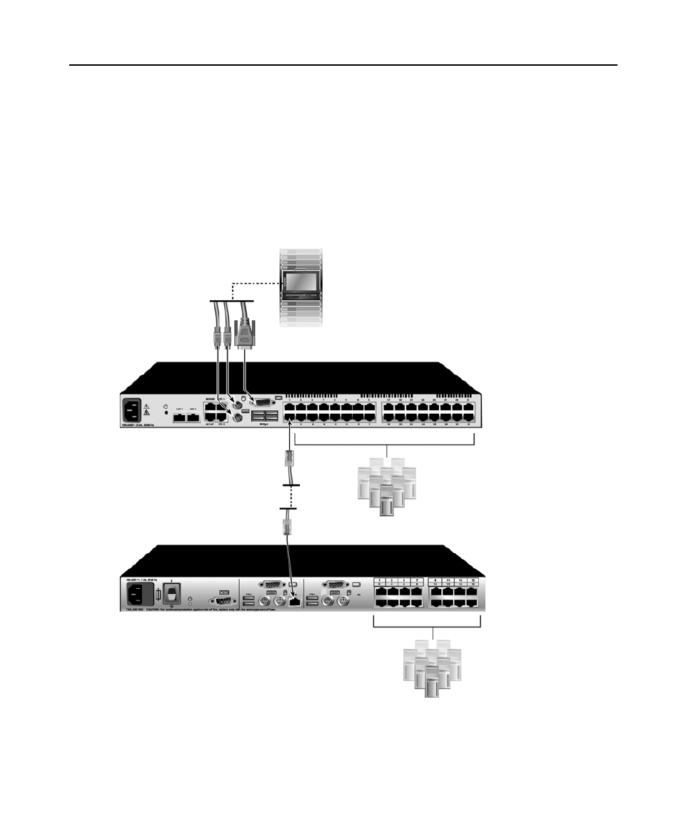
Tiering Multiple KVM Switches
You can tier a digital KVM switch with an analog KVM switch to enable multiple target devices
depending on your configuration. Make sure the digital KVM switch is the top tier; the digital
KVM switch is not designed to be part of the second tier.
Figure 2.2: KVM switch configuration with a tiered KVM switch
Local user
AP5615 switch (main)
Primary
target devices
ACI port
Secondary
target devices
AP5602 switch (tiered)

Chapter 2: Installation 10
NOTE: To open a virtual media session with a target device, the target device must first be connected to the KVM
switch using a KVM USB VM server module or KVM PS/2 VM server module.
To tier multiple KVM switches:
1. Connect the tiered KVM switch to each target device as described in Connecting the KVM
switch on page 6.
2. Connect the peripheral devices to the local user port on the digital KVM switch. See Verifying
Ethernet connections on page 8.
3. Attach one end of the CAT5 cable to the ACI port on the analog KVM switch.
4. Attach the other end of the CAT5 cable to one of the target device interface ports on the rear of
the digital KVM switch.
5. The switching system automatically merges the two KVM switches. All target devices
connected to the tiered KVM switch are included in the main KVM switch target device list in
the OSD interface. Repeat steps 3 and 4 for all additional tiered KVM switches you attach.
Installing And Starting Up The Web Interface
Once you have installed a new digital KVM switch, you can use the web interface to configure unit
parameters and launch video sessions.
Supported browsers
The web interface supports the following browsers:
• Microsoft Internet Explorer
® version 6.0 or later
• Mozilla Firefox® version 2.0 or later
• Netscape Navigator® version 7.0 or later
Launching the web interface
To launch the web interface:
1. Open a web browser and type the IP address of the KVM switch. You can set the IP address of
the KVM switch using the OSD or the serial port.
2. The log in window opens. Type your user name and password and click OK.
3. The web interface opens and displays the Connections tab.
NOTE: Once you have logged in to the web interface, you will not have to log in again when launching new
sessions unless you have logged out or your session has exceeded the inactivity timeout specified by the
administrator.

Chapter 2: Installation 11
Installing And Starting Up The Network Access Software
Supported operating systems
The following operating systems are supported by the Network Access Software:
• Microsoft® Windows® 2000 Workstation Service Pack 4
• Microsoft Windows 2000 Server Service Pack 4
• Microsoft Windows XP (Home and Professional) Service Pack 2
• Microsoft Windows Server 2003 Service Pack 1
• Red Hat Enterprise Linux 3.0 WS
• Red Hat Enterprise Linux 4.0 WS
• SuSE Linux Enterprise Server 8
• SuSE Linux Enterprise Server 9
• SuSE Linux 9.2
• SuSE Linux 9.3
Hardware configuration requirements
The software is supported on the following minimum computer hardware configurations:
• 500 MHz Pentium III
• 256 MB RAM
• 10BASE-T or 100BASE-T NIC
• XGA video with graphics accelerator
• Desktop size must be a minimum of 800 x 600
• Color palette must be a minimum of 65,536 (16-bit) colors
Browser requirements
You will need one of the following browsers installed on the computer to run the Network Access
Software:
• Internet Explorer 5.0 or later (Windows only)
• Netscape 6.0 or later
• Mozilla™ 1.4 or later
• Firefox 1.0 or later
Installing the software
To install on Microsoft Windows operating systems:
1. Insert the CD included with the KVM switch into the CD drive.

Chapter 2: Installation 12
If AutoPlay is supported and enabled, the setup program starts automatically.
— or —
If the computer does not support AutoPlay, set the default drive to the CD drive letter and
execute the following command to start the install program (replace “drive” with the CD drive
letter on the system): drive:\Network Access Software\win32\setup.exe
2. Follow the on-screen instructions.
To install on Linux operating systems:
1. Insert the CD included with KVM switch into the CD drive.
When using Red Hat and SUSE Linux distributions, the CD will usually be mounted
automatically.
Continue with step 2 if the CD mounts automatically.
If the CD does not mount automatically, issue the mount command manually. The following is
an example of a typical mount command:
mount -t iso9660 device_file mount_point
where device_file is the system-dependent device file associated with the CD and mount_point
is the directory that will be used to access the contents of the CD after it is mounted. Typical
default values include "/mnt/cdrom" and "/media/cdrom".
See the Linux operating system documentation for the specific mount command syntax to use.
2. Open a command window and navigate to the CD. For example:
cd /mnt/cdrom
3. Enter the following command to start the install program:
sh ./Network Access Software/linux/setup.bin
4. Follow the on-screen instructions.
During installation
You are prompted to select the location where the application will be installed. Select an existing
path or type a directory path. The default path for Windows 2000, 2003 and XP systems is the
program files directory. The default path for Linux systems is the usr/lib directory.
If you enter a path that does not exist, the installation program automatically creates it during
installation.
You can also indicate if you want a Network Access Software icon installed on the desktop.

Chapter 2: Installation 13
Uninstalling the software
To uninstall the software on Microsoft Windows, starting at the Control Panel:
1. Open the Control Panel and select Add/Remove Programs. A sorted list of currently installed
programs opens.
2. Select the Network Access Software entry.
3. Click the button. The uninstall wizard starts.Change/Remove
4. Click the Uninstall button and follow the on-screen instructions.
To uninstall the software on Microsoft Windows, using a command window:
1. Open a command window and change to the Network Access Software install directory used
during installation. The default path for win32 systems is the program files directory.
2. Change to the UninstallerData subdirectory and enter the following command (the quotation
marks are required):
“Uninstall APC Network Access Software.exe”
The uninstall wizard starts. Follow the on-screen instructions.
To uninstall the software on Linux:
1. Open a command window and change to the Network Access Software install directory used
during installation. The default path for Linux systems is the usr/lib directory.
2. Change to the UninstallerData subdirectory and enter the following command:
sh ./Uninstall_APC_Network_Access_Software
The uninstall wizard starts. Follow the on-screen instructions.
Opening the software
To open the software on Microsoft Windows:
1. Select Start - Programs - Network Access Software.
2. Double-click the Network Access Software icon.
To open the software on Linux:
1. Enter the command:
/Network_Access_Software
2. From (/user/bin), enter the following link:
/APC_Network_Access_Software
3. If a desktop shortcut was created on installation, double-click the shortcut.

Chapter 2: Installation 15
exceed circuit capabilities. Overloaded power sources and extension cords present fire and shock
hazards.
Elevated Ambient Temperature: If the unit is installed in a closed rack assembly, the operating
temperature of the rack environment may be greater than room ambient temperature. Do not exceed
the rated maximum ambient temperature of the switch.
Reduced Air Flow: Install the equipment in the rack so that the amount of airflow required for safe
operation of the equipment is not compromised.
Reliable Earthing: Maintain reliable earthing of rack-mounted equipment. Pay particular attention
to supply connections and indirect connections to the branch circuit (for example, use of power
strips).
Installing a rack mounting bracket
To install a rack mounting bracket:
1. Attach the brackets to the switch using the six provided screws.
2. Install the cable support rod on the lower side of the slide extensions.
3. Slide the extension assembly into the bracket assembly.
4. Place the complete bracket assembly into a level rack position and install the appropriate
hardware (not included) into each of the four bracket corners.

16
CHA PT ER
3
Basic Operations
Controlling The Switching System From The Analog Port
The APC KVM switch includes ports on the rear panel to connect a keyboard, monitor and mouse
for direct analog access. The KVM switch uses the On-Screen Display (OSD), which has menus to
configure the switching system and select target devices. Devices can be identified by customizable
names.
Starting The OSD
You can view, configure and control target devices in the switching system from the OSD interface
from a KVM connection to the analog port.
To start the OSD interface, press Print Screen. Alternatively, you can press the Control, Alt or
Shift key twice within one second to start the OSD interface. You can use any of these key
sequences instead of pressing Print Screen in any procedure in this document. To specify which key
sequences can be used to start the OSD interface, click Setup - Menu.
The Main window lists the target devices in the switching system. You can sort the list by clicking
the Name, eID or Port button.
The Port column indicates the ta h each target device is connected. rget device interface port to whic
The status of each target device in the switching system is indicated by one or more status symbols
in the right column. The following table describes the status symbols.

Chapter 3: Basic Operations 17
You can set a screen delay to specify the length of time that elapses between when Print Screen is
pressed and when the OSD interface starts.
To set a screen delay:
1. Press Print Screen to start the OSD interface.
2. In the Main window, click Setup — Menu.
3. In the Screen Delay Time field, type the number of seconds you want to elapse between when
Print Screen is pressed and when the OSD interface starts.
Connecting A User To A Target Device
Use the Main window of the OSD to select a target device to connect. When you select a target
device, the keyboard and mouse are automatically reconfigured to the correct settings for that target
device.
To select a target device:
1. Press Print Screen to start the OSD.
2. Double-click the target device name, eID number or port number in the main window
— or —
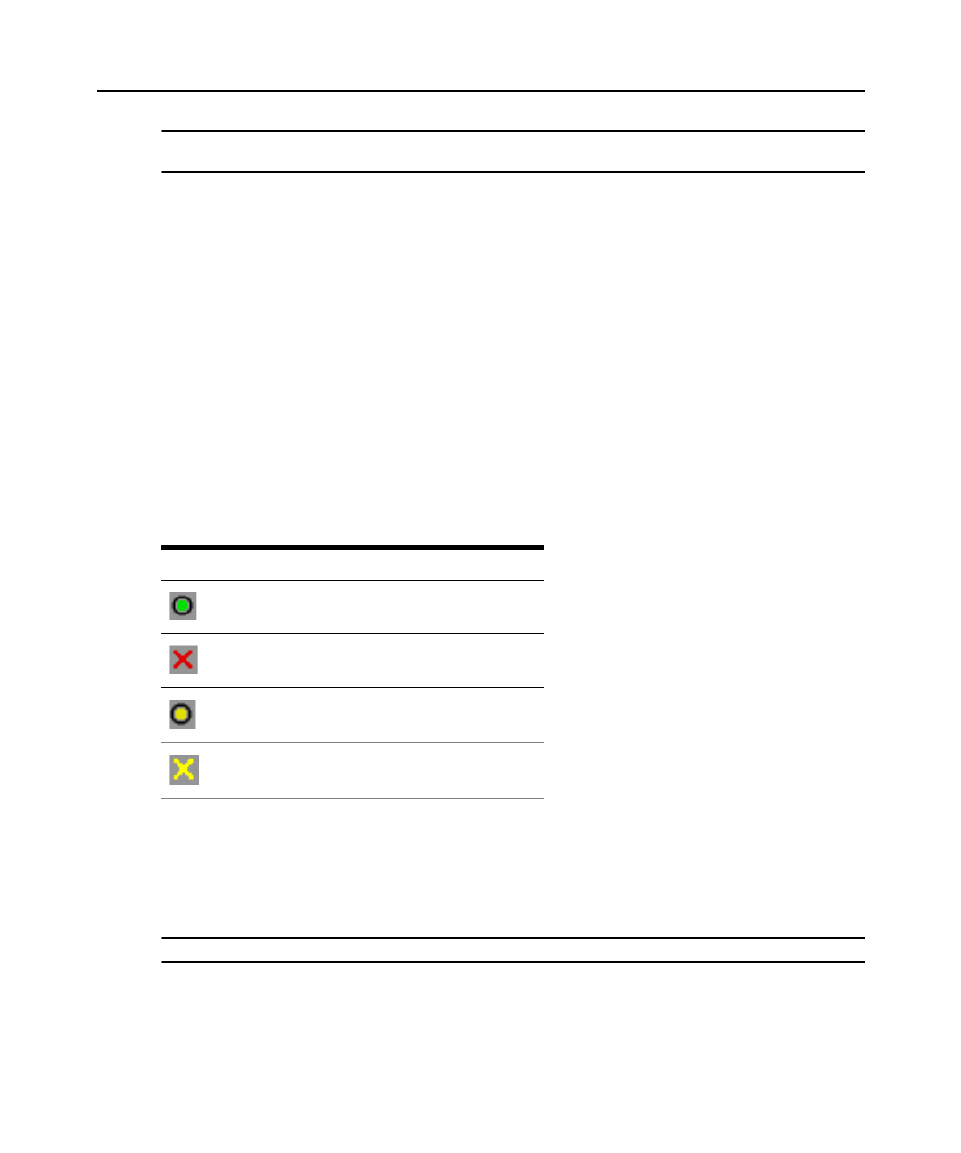
Table 3.1: OSD interface status symbols
Symbol Description
The KVM server module is online (green circle).
The KVM server module is offline or is not operating correctly.
The target device is tiered through another KVM switch. The
target device and the KVM switch are online and have power.
The target device is tiered through another KVM switch. The
KVM switch is offline or does not have power.
The firmware for the KVM server module is being upgraded
(yellow circle). When this symbol is visible, do not turn off and
turn on the KVM switch or connected target devices and do not
disconnect the KVM server module. Doing so might damage the
KVM server module permanently.
The KVM server module is being accessed by the indicated
user channel (green channel letter).
The KVM server module is blocked by the indicated user
channel (black channel letter).
A remote virtual media connection is established to the target
device connected to the indicated user channel (blue letter).

Chapter 3: Basic Operations 18
Type the port number and press Enter
— or —
Type the first few characters of the target device name or eID number, and press Enter.
You can also toggle between two selected target devices.
To select the previously selected target device:
Press Print Screen and then press Backspace.
To disconnect the user from a target device:
Press Print Screen and press Alt+0. A Free status flag in the OSD indicates the user is not
connected to a target device.
Using The OSD
Table 3.2 describes the keys, key combinations and mouse actions you can use in the OSD. Two or
more key names or mouse actions separated by commas indicate a sequence of actions. Two or
more key names or mouse actions separated by a plus sign (+) indicate a combination of actions;
they are performed simultaneously.
You can use the main keyboard or the numeric keypad to type numerals, except when you use the
Alt+0 Alt+0 key combination; you must use the 0 key on the main keyboard when you use .
Table 3.2: OSD interface navigation basics
Key, key combination, or
mouse action Result
Print Screen; Ctrl, Ctrl; Shift,
Shift; or Alt, Alt
Start the OSD interface. To specify which key sequences can be used to start
the OSD interface, click Setup > Menu.
Print Screen, Print Screen Send the Print Screen keystroke to the currently selected target device. A
screen capture will be performed for the target device.
If Print Screen is not selected as a startup key sequence in Setup > Menu,
you only need to press Print Screen once to take a screen capture of the
target device.
F1 Display help for the current window.
Escape In the OSD main window: Close the OSD interface and return to the status
flag on the desktop.
In all other windows: Close the current window, without saving changes, and
return to the previous window.
In pop-up windows: Close the pop-up window and return to the current
window.
Alt+X Close the current window, without saving changes, and return to the previous
window.

Chapter 3: Basic Operations 19
Configuring The KVM Switch And The OSD
To configure the KVM switch and the OSD interface:
Start the OSD and click Setup.
The following table describes the options in the Setup window.
Alt+O Click OK and return to the previous window.
Alt+port number Select a target device to be scanned; port number is the port number of the
target device.
Enter Completes a switch in the Main window and exits the OSD interface.
Print Screen, Backspace Return to the previously selected target device.
Print Screen, Alt+0 Disconnect the user from the selected target device. The zero must be typed
on the main keyboard, not the numeric keypad.
Print Screen, Pause Start the screen saver immediately and lock the user, if it is
password-protected.
Up Arrow or Down Arrow Move the cursor from line to line in a list.
Right Arrow or Left Arrow When editing text in a field: Move within the text in the field.
All other conditions: Move the cursor from column to column in a list.
Page Up or Page Down Page through a list or help window.
Home or End Move the cursor to the top or bottom of a list.
Delete Delete the selected characters in a field or the selected item in the scan list.
For more information about scan lists see Scanning The Switching System
on page 31.
Table 3.2: OSD interface navigation basics (Continued)
Key, key combination, or
mouse action Result

Chapter 3: Basic Operations 20
Assigning target device names
Use the Names window to identify individual target devices by name rather than by port number.
The Names list is always sorted by port order. Names are stored in the KVM server module, so
even if you move the cable or target device to another target device interface port, the name and
configuration are recognized by the KVM switch. If a target device is turned off, you cannot
modify the name of the KVM server module.
To access the Names window:
1. Press Print Screen to start the OSD. The Main window opens.
2. Click Setup — Names. The Names window opens.
If new KVM server modules are discovered by creen list will be the KVM switch, the on-s
automatically updated. The mouse cursor will change into an hourglass during the update. No
mouse or keyboard input will be accepted until the list update is complete.
To assign names to target devices:
1. In the Names window, select a target device name or port number and click Modify. The Name
Modify window opens.
2. Type a name in the New Name field. Names of target devices can be up to 15 characters long.
Valid characters are A-Z, a-z, 0-9, space and hyphen.
Table 3.3: Setup features to manage routine tasks for the target devices
Option Purpose
Menu Order the list of target devices by target device name, eID number, or port number. Set a
screen delay to specify the length of time that elapses between when Print Screen is
pressed and when the OSD interface starts.
Security Set passwords to restrict access to the target devices. Enable the screen saver.
Flag Change the display properties including timing, color, and location of the status flag.
Language Specify the language in which the interface is displayed.
Devices Specify the number of ports that are on the attached tiered KVM switch.
Names Assign a unique name to each target device.
Keyboard Specify the keyboard country code.
Broadcast Simultaneously control multiple target devices through keyboard and mouse actions.
Scan Set up a custom scan pattern for up to 16 target devices.
Preempt Specify preemption settings.
Network Specify the network speed and configuration, IP address, subnet mask, and gateway for the
switching system.

Chapter 3: Basic Operations 21
3. Click OK to transfer the new name to the Names window. The selection is not saved until you
click OK in the Names window.
4. Repeat steps 1 to 3 for each target device in the switching system.
5. Click OK.
If a KVM server module has not been assigned a name, the eID is used as the default name. To list
target devices alphabetically by name, press Alt+N or click Name in the Main window.
Assigning device types
The KVM switch automatically discovers an attached tiered analog KVM switch, but you must
specify the number of ports on the tiered KVM switch through the Devices window. KVM switches
are listed in the Type category for the tiered KVM switch. When you select a configurable KVM
switch from the list, the Modify button becomes available, so you can assign it the correct number
of ports.
To access the Devices window:
1. Press Print Screen to start the OSD. The Main window opens.
2. Click Setup — Devices. The Devices window opens.
When the KVM switch discovers a tiered KVM switch, the port numbering changes to
accommodate each target device under that KVM switch. For example, if the KVM switch is
connected to target device interface port 6, the KVM switch port is listed as 06, and the target
devices under it are numbered sequentially as 06-01, 06-02 and so on.
To assign a device type:
1. In the Devices window, select the port number, then click Modify. The Device Modify window
opens.
2. Select or type the number of ports that are supported by the tiered KVM switch and click OK.
3. Repeat steps 1 and 2 for each port for which you want to assign a device type.
4. Click OK in the Devices window to save settings.
Changing the display behavior
Use the Menu window to change the order of the target devices and set a screen delay for the OSD
interface. The display order settin et devices are listed in several g affects the order in which targ
windows, including the Main, Devices and Broadcast windows.
To access the Menu window:
1. Press Print Screen to start the OSD. The Main window opens.
2. Click Setup — Menu. The Menu window opens.
To select the order of the target devices:
1. Select Name to list the target devices alphabetically by target device name.

Chapter 3: Basic Operations 22
— or —
Select eID to list the target devices numerically by eID number.
— or —
Select Port to list the target devices numerically by port number.
2. Click OK.
To select a key combination to start the OSD interface:
1. In the Invoke OSD section, select the key combinations that will start the OSD, then press your
selected combination.
2. Click OK.
You can set a screen delay so that you can select a target device using the keyboard without starting
the OSD. A screen delay specifies the length of time that elapses between when Print Screen is
pressed and when the OSD starts.
To set a screen delay:
1. Type the number of seconds (0-9) to specify the length of time that elapses between when Print
Screen is pressed and when the OSD starts. If you specify 0, there is no delay.
2. Click OK.
Selecting display language
Use the Setup window to change the display language for the OSD.
To select a language for the OSD:
1. Press Print Screen to start the OSD. The Main window opens.
2. Click Setup — Language. The Language window opens.
3. In the Language window, select the language and click OK.
Controlling the status flag
The status flag is displayed on the desktop and indicates the name or eID number of the selected
target device or the status of the selected port. You can specify the information displayed in the
flag, the flag color, whether the desktop is visible through the flag, whether the flag is displayed all
the time and where the flag is displayed on the desktop. The following table shows examples of
status flags.

Chapter 3: Basic Operations 23
To specify the status-flag settings:
1. Press Print Screen. The Main window opens.
2. Click Setup > Flag.
3. (Optional) Select Name or eID to specify the information displayed in the flag.
4. (Optional) Select Displayed to display the flag all the time, or select Timed to display the flag
for only five seconds after you select a target device.
5. (Optional) In the Display Color section, select the flag color.
6. (Optional) Select Opaque to make the flag solid, or select Transparent to make the desktop
visible through the flag.
7. (Optional) To specify the position of the flag:
a. Click Set Position.
b. Hold down the left mouse button on the title bar of the Set Position window and drag the
window to the new location.
c. Press the right mouse button to close the Set Position window.
8. Click OK to save the changes.
Setting the keyboard country code
By default, the KVM switch sends the US keyboard country code to USB cables attached to target
devices, and the code is applied to the target devices when they are turned on or rebooted. Codes
are then stored in the KVM server module. Using a keyboard code that supports a language
different from that of the KVM switch firmware will cause incorrect keyboard mapping.
If multiple keyboards are connected to the local port, they must be of the KVM server module type
(PC or Mac) and of the KVM server module language. Only local users can view or change
keyboard country code settings.
Issues might arise when you use the US keyboard country code with a keyboard of another country.
For example, the Z key on a US keyboard is in the KVM server module location as the Y key on a
German keyboard.
Table 3.4: OSD interface status flags
Flag Description
Flag type by name.
Flag type by eID number.
Flag indicating that the user has been disconnected
from all systems.
Flag indicating that Broadcast mode is enabled.

Chapter 3: Basic Operations 24
You can use the Keyboard window to send a different keyboard country code than the default US
setting.
To change the keyboard country code:
1. Press Print Screen to start the OSD. The Main window opens.
2. Click Setup — Keyboard. The Keyboard window opens.
3. Select the country code for the keyboard and click OK. Confirm the change in the Keyboard
Warning window.
4. Click OK.
Setting KVM switch security
You can enable a screen saver to start if the user remains inactive for a specified length of time.
When the screen saver starts, the user is disconnected from any target device to which it was
connected. The screen saver stops when you press any key or move the mouse.
If you set a password, the keyboard and mouse are locked when the screen saver starts. When you
press a key or move the mouse while the screen saver is running, a Password window opens, and
you must type the password and click OK to unlock the keyboard and mouse.
NOTE: If you forget the password, you must call APC technical support.
To immediately start the screen saver:
Press Print Screen and click Pause.
To enable the screen saver:
1. Press Print Screen. The main window opens.
2. Click Setup — Security. If a password is set, the Password window opens. Type the password
and click OK.
3. Select the Enable Screen Saver checkbox.
4. In the Inactivity Time field, type the number of seconds (1-99) that must elapse before the
screen saver starts.
5. If the monitor is Energy Star compliant, select Energy; otherwise, select Screen.
6. (Optional) To run the screen-saver test, click Test. The screen-saver test runs for 10 seconds.
7. Click OK.
To disable the screen saver:
1. Press Print Screen. The main window opens.
2. Click Setup — Security. If a password is set, the Password window opens. Type the password
and click OK.
3. Clear the Enable Screen Saver checkbox.

Chapter 3: Basic Operations 25
4. Click OK.
A password must contain both alphabetic and numeric characters and can contain up to 12
characters. Passwords are case-sensitive. Valid characters are A-Z, a-z, 0-9, space and hyphen.
To set or change a password:
1. Press Print Screen. The main window opens.
2. Click Setup — Security. If a password is already set, the Password window opens. Type the
password and click OK.
3. Double-click the New field.
4. In the New field, type the new password.
5. In the Repeat field, type the password again.
6. Click OK.
To disable password protection:
1. Press Print Screen. The main window opens.
2. Click Setup — Security. In the Password window, type the password and click OK.
3. Double-click the New field. Leave the field blank and press Enter.
4. Double-click the Repeat field. Leave the field blank and press Enter.
5. Click OK.
Setting The Preemption Warning
Administrators and users with certain access rights can preempt (disconnect) KVM sessions and
take control of the target device. You can choose whether to warn the first user the session will be
preempted and specify how long the KVM switch will wait for the first user to respond to the
warning.
For more information on page 76.about preemption, see Using Preemption
To view or change the preemption warning settings:
1. Press Print Screen. The main window opens.
2. Click Setup — Preempt.
3. Enter a number of seconds in the Timeout Seconds field.
NOTE: If you enter a value of 0-4 seconds, the first user will not be warned before the session is preempted. If
you enter a value of 5-120 seconds, the first user will be warned and will be allowed to continue using the target
device for up to the amount of time in the Timeout Seconds field. The session will be preempted when the user
clicks OK, or when the specified time elapses.
4. Click OK to save the settings.

Chapter 3: Basic Operations 26
Managing Target Device Tasks Using The OSD
From the Commands window, you can manage the switching system and user connections, enable
the Scan and Broadcast modes, and update the firmware.
To access the Commands window:
1. Press Print Screen. The Main window opens.
2. Click Commands. The Commands window opens.
Displaying version information
You can use the OSD to view the versions of the KVM switch and the KVM server module
firmware.
To view version information:
1. Press Print Screen. The Main window opens.
2. Click Commands — Display Versions. The Version window opens. The top pane of the window
lists the subsystem versions in the KVM switch.
3. Click the KVM server module button to view individual KVM server module version
information. The KVM server module Select window opens.
4. Select a KVM server module to view and click the Version button. The KVM server module
Version window opens.
5. Click X to close the KVM server module Version window.
Table 3.5: Commands to manage routine tasks for the target device
Feature Purpose
KVM server
module Status
View the version and upgrade status of the KVM server module.
Display Config View current display settings.
Run Diagnostics Configure and begin diagnostics on target devices.
Broadcast Enable Begin broadcasting to the target devices. Configure a target device list for broadcasting
under the Setup window.
Scan Enable Begin scanning the target devices. In the Setup window, set up a target device list for
scanning.
User Status View and disconnect users.
Display Versions View version information for the KVM switch as well as view and upgrade firmware for
individual KVM server modules.
Device Reset Re-establish operation of the keyboard and mouse.

Chapter 3: Basic Operations 27
Upgrading the firmware
You can also use the OSD interface to upgrade the firmware available for the KVM switch. For
optimum performance, keep the firmware current. For more information on upgrading firmware,
see “Appendix A” beginning on page 105.
To upgrade firmware:
1. Press Print Screen. The Main window opens.
2. Click Commands — Display Versions — Upgrade. The Upgrade window opens.
3. Click Upgrade. A Warning window opens. Click OK to open the Upgrade Process window.
The progress of the upgrade is indicated in the Programmed field.
Viewing the display configuration
Use the Display Configuration window to view the current configuration of the switching system.
To view the current configuration:
Click Commands — Display Config. The Display Configuration window opens and lists the current
system configuration values.
Viewing and disconnecting user connections
You can view and disconnect users from target devices through the User Status window. You can
display either the target device name or eID number to which a user is connected. If there is no user
connected to a channel, the User and Server Name fields are blank.
To view current user connections:
Click Commands — User Status. The User Status window opens.
To disconnect a user:
1. From the User Status window, click the letter that corresponds to the user to disconnect. The
Disconnect window opens.
2. Click OK to disconnect the user and return to the User Status window.
If the User Status list has changed since it was last visible, the mouse cursor will turn into an
hourglass as the list is automatically updated. No mouse or keyboard input is accepted until the list
update is complete.
Resetting the keyboard and mouse
If the local keyboard and mouse are not responding, reset the local keyboard and mouse and reset
the keyboard and mouse on the target device.
When you reset the keyboard and mouse on the target device, the keyboard and mouse settings are
sent to the KVM switch and communication is re-established between the KVM switch and the
target device.
Chapter 3: Basic Operations 28
NOTE: This function is for Microsoft Windows-based computers only. Resetting the keyboard and mouse on a
target device running any other operating system might require you to reboot that target device.
To reset the local mouse and keyboard
1. Press Print Screen. The Main window opens.
2. Click Commands — Device Reset.
3. Click Version > Reset. A message is displayed stating the mouse and keyboard are reset.
4. Click OK.
Power Controlling Devices
Power window
Through the Power window, you can view which outlets control which devices and whether the
outlet is on or off. You can also turn on, turn off or cycle power to a selected device. The status of
each outlet is indicated by one or more status symbols in the right column. Table 3.6 describes the
status symbols.
To turn on, turn off or cycle power to a device:
1. Press Print Screen. The Main window opens.
2. Click Commands - Power.
3. Select the device you wish to control.
NOTE: Multiple devices may be selected.
4. Click On, Off or Cycle, as appropriate.
Table 3.6: Power Window Status Symbols
Symbol Description
Outlet is on.
Outlet is off.
Outlet is waiting to go on.
Outlet is waiting to go off.
Chapter 3: Basic Operations 29
PDUs window
Through the PDUs window, you can view which rack PDUs are connected to your system. The
status of each rack PDU is indicated by one or more status symbol in the right column. Table 3.7
describes the status symbols.
To view connected rack PDUs:
Open the PDUs window. The window contains a listing of all rack PDUs attached to your system.
PDU Settings window
From the PDUs window, you can view the PDU Settings window, which allows you to view and
modify rack PDU parameters.
To view/modify PDU settings:
1. Press Print Screen. The Main window opens.
2. Click Setup - PDUs.
3. Complete one of the following steps:
Select a rack PDU name, then click Settings to open the PDU Settings window.
— or —
Select a rack PDU name, then press Enter to open the PDU Settings window.
— or —
Double-click on the rack PDU name to open the PDU Settings window.
4. Complete any of the following steps:
a. In the Name field, enter the rack PDU name.
b. In the Cycle Delay field, enter the number of seconds you want the KVM switch to wait
between turning off and turning on.
5. Click OK.
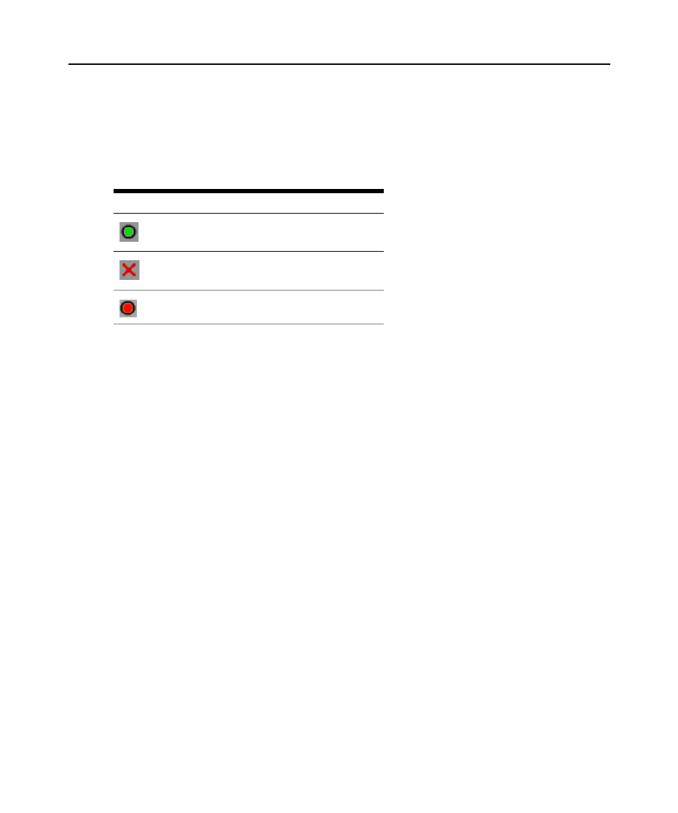
Table 3.7: PDUs WIndow Status Symbols
Symbol Description
Outlet is online.
Outlet is offline.
Outlet is overloaded.

Chapter 3: Basic Operations 30
PDU Inlets window
From the Inlets window, you can view and modify inlet parameters.
NOTE: You can only modify inlet parameters on a PDU that is currently online.
To view/modify PDU Inlet settings:
1. Press Print Screen. The Main window opens.
2. Click Setup - PDUs.
3. Complete one of the following steps:
Select a rack PDU name, then click Settings to open the PDU Settings window.
— or —
Select a rack PDU name, then press Enter to open the PDU Settings window.
— or —
Double-click on the rack PDU name to open the PDU Settings window.
4. Click Inlets.
5. Enter an integer in the Minimum Amps or Maximum Amps fields.
6. Click OK.
PDU Outlets window
From the Outlets window, you can select an outlet and open the Outlet Settings window to set
outlet-specific parameters.
NOTE: You can only modify outlet parameters on a PDU that is currently online.
To view/modify PDU Outlet settings:
1. Press Print Screen. The Main window opens.
2. Click Setup - PDUs.
3. Complete one of the following steps:
Select a rack PDU name, then click Settings to open the PDU Settings window.
— or —
Select a rack PDU name, then press Enter to open the PDU Settings window.
— or —
Double-click on the rack PDU name to open the PDU Settings window.
4. Click Outlets.

Chapter 3: Basic Operations 31
5. Complete one of the following steps:
Select an outlet, then click Settings to open the Outlet Settings window.
— or —
Select an outlet, then press Enter to open the Outlet Settings window.
— or —
Double-click an outlet to open the Outlet Settings window.
6. Select the outlet you wish to modify.
7. Complete any of the following steps:
a. In the Name field, enter the Outlet name.
b. In the Power-On Interval field, enter the number of seconds you want the KVM switch to
wait between turning off and turning on.
NOTE: The Power-On Interval must be an integer between 0 and 7200.
8. Click OK.
Scanning The Switching System
In scan mode, the KVM switch automatically scans from port to port (target device to target
device). Use scan mode to monitor the activity of up to 16 target devices and to specify which
target devices to scan and the number of seconds each target device will be visible. The target
devices are scanned in the order in which they are listed. You can choose to list the target devices
by name, eID number or port number by clicking the corresponding button.
To add target devices to the scan list:
1. Click Setup — Scan. The Scan window opens.
2. The window contains a listing of all target devices attached to the KVM switch. Select the
checkbox next to the target devices to scan.
— or —
Double-click on the target device name or port to scan.
— or —
Press Alt and the eID number of the target device to scan. You can select up to 16 target
devices from the list.
3. In the Time field, type the number of seconds (from 3 to 255) that must elapse before the scan
moves to the next target device in the sequence.
4. Click OK.

Chapter 3: Basic Operations 32
To remove a target device from the scan list:
1. In the Scan window, clear the checkbox next to the target device to remove.
— or —
Double-click on the target device name or port to remove.
— or —
Press Shift + Delete to remove the selected target device and all entries below it.
— or —
Click the Clear button to remove all target devices from the scan list.
2. Click OK.
To start the Scan mode:
1. Click Commands. The Commands window opens.
2. Select Scan Enable in the Commands window. Scanning will begin immediately.
3. Click X to close the Commands window.
To cancel scan mode:
If the OSD is open, select a target device.
— or —
If the OSD is not open, move the mouse or press any key on the keyboard to stop scanning at the
currently selected target device.
Running Switching System Diagnostics
You can validate the integrity of the switching system through the Run Diagnostics command. This
command checks the main board functional sub-systems (memory, communications, KVM switch
control and the video channels) for each system controller.
The top section of the Diagnostics window displays the hardware tests. The bottom portion divides
the tested KVM server modules into three categories: Online, Offline or Suspect. KVM server
modules might be listed as offline while being upgraded.
The following table details each of the tests.
Table 3.8: Diagnostic test details
Test Description
Firmware CRCs Reports on the condition of the main board RAM.
Remote User Video Reports on the condition of the remote user video.

Chapter 3: Basic Operations 33
To run diagnostic tests:
1. Click Commands — Run Diagnostics. A warning message indicates all users will be
disconnected.
2. Click OK to begin diagnostics.
All users are disconnected and the Diagnostics window opens. As each test is finished, a pass
(green circle) or fail (red x) symbol is visible to the left of the item. The test is complete when
the last test symbol is visible.
Broadcasting To Target Devices
The analog user can simultaneously control more than one target device in a switching system to
ensure all selected target devices receive identical input. You can choose to independently
broadcast either of the following actions:
• Broadcasting keystrokes — The keyboard state must be identical for all target devices
receiving a broadcast to identically interpret keystrokes. Specifically, the Caps Lock and Num
Lock modes must be the same on all keyboards. While the KVM switch attempts to send
keystrokes to the selected target devices simultaneously, some target devices might inhibit and
thereby delay the transmission.
• Broadcasting mouse movements — For the mouse to work accurately, all systems must have
identical mouse drivers, desktops (such as identically placed icons) and video resolutions. In
addition, the mouse must be in exactly the same place on all screens. Because these conditions
are difficult to achieve, broadcasting mouse movements to multiple systems might have
unpredictable results.
You can broadcast to up to 16 target devices at a time, one target device per target device interface
port.
To access the Broadcast window:
1. Press Print Screen. The Main window opens.
2. Click Setup > Broadcast. The Broadcast window opens.
LAN Connection Reports on the condition of the LAN connection.
Online KVM server
modules
Indicates the total number of currently connected and turned on KVM server modules.
Offline KVM server
modules
Indicates the number of KVM server modules that have been connected successfully
in the past and are turned off.
Suspect KVM server
modules
Indicates the number of KVM server modules that have been detected, but are either
unavailable for connection or have dropped packets during the ping tests.
Table 3.8: Diagnostic test details

Chapter 3: Basic Operations 34
To broadcast to selected target devices:
1. Complete one of the following steps:
• From the Broadcast window, select the Mouse or Keyboard checkboxes for the target
devices that are to receive the broadcast commands.
• Press the Up or Down Arrow keys to move the cursor to the target device. Then press
Alt+K to select the Keyboard checkbox or Alt+M to select the Mouse checkbox. Repeat for
additional target devices.
2. Click OK to save the settings and return to the Setup window, or click X or press Escape to
return to the Main window.
3. Click Commands. The Commands window opens.
4. Select the Broadcast Enable checkbox to activate broadcasting. The Broadcast Enable
Confirm/Deny window opens.
5. Click OK to enable the broadcast, or click X or press Escape to cancel and return to the
Commands window.
6. If broadcasting is enabled, type the information or perform the mouse movements that you
want to broadcast from the user station. Only target devices in the list are accessible. The other
user is disabled when broadcast mode is enabled.
To turn broadcasting off:
From the Commands window, clear the Broadcast Enable checkbox.

35
CHA PT ER
4
Network Access Software
About the Network Access Software
The Network Access Software is the main GUI (Graphical User Interface) for the software. You
can view, access, manage and create custom groupings for all supported units.
When you start the software, the main Network Access Software window opens.
Window Features
The Network Access Software window is divided into areas: the View Selector buttons, the Group
Selector pane and the Unit Selector pane. The content of these areas changes, based on whether a
target device or an APC KVM switch is selected or what task is to be completed. Figure 4.1 on
page 36 shows the window areas; descriptions follow in Table 36.4.1 on page
Click one of the View Selector buttons to view the switching system organized by categories:
KVM switches, Servers, Sites, or Folders. The Network Access Software’s default display is user-
configurable. For more information, see Customizing the window display on page 37.

Chapter 4: Network Access Software 36
Figure 4.1: Network Access Software window
Table 4.1: Network Access Software window areas
Area Description
A Menu bar: Provides access to many of the features in the software.
B View Selector pane: Contains View Selector buttons for choosing the Network
Access Software view. Clicking a button shows the switching system organized
by the button category: KVM switches, Servers, Sites or Folders. You can
configure which button is visible by default.
C Unit list: Displays a list of target devices, KVM switches and other selectable
units contained in the currently selected group or the results of the search
executed from the Search bar.
D Status bar: Displays the number of units shown in the Unit list.
E Unit Selector pane: Contains the Search bar, Unit lists and Task buttons that
correspond to the selected view or group.
F Search bar: Gives you the ability to search the database for the text entered in
the Search field.
G Task buttons: Represent tasks that can be executed. Some buttons are
dynamic, based on the unit selected in the Unit list, while other buttons are fixed
and always present.
D
A
B
C
E
G
F

Chapter 4: Network Access Software 37
Customizing the window display
You can resize the Network Access Software window at any time. Each time you start the
application, the Network Access Software window opens to its default size and location.
A split-pane divider that runs from top to bottom separates the Group Selector pane and the Unit
Selector pane. You can move the divider left and right to change the viewing area of these two
panes. Each time the Network Access Software is opened, the divider returns to its default location.
You can specify which view (KVM switches, Servers, Sites or Folders) is visible on startup or you
can let the Network Access Software determine it.
You can change the order and sorting of the Unit list by clicking the sort bar above the column. An
upward-pointing arrow in a column header indicates that the list is sorted by that field name in
ascending order. A downward-pointing arrow indicates the list is sorted by that field name in
descending order.
Adding A KVM Switch
Before you can access the KVM switch through the software, you must add it to the software
database. After a KVM switch is added, it is visible in the Unit list. You can either manually add or
discover a KVM switch.
To manually add a KVM switch with an assigned IP address:
1. Select File — New — KVM switch from the Network Access Software menu.
— or —
Click the New KVM switch button.
The New KVM switch Wizard opens. Click Next.
2. Select the type of KVM switch you are adding. Click Next.
3. Click Yes to indicate the KVM switch has an assigned IP address, then click Next.
4. Type the IP address and click Next.
5. The software searches for the KVM switch.
The software searches for the indicated unit as well as all the KVM server modules and target
device names you associated with it in the OSD, if any. To search for KVM server modules
that are not receiving power, access the resync feature in the Servers category of the web
interface and select the Include Offline Server Access Modules checkbox.
The Enter Tier Switch Information window opens if the software detects an attached tiered
switch. This window contains a list of all ports and KVM server module eIDs (Electronic
Identification Numbers) retrieved from the KVM switch and the tiered switch types to which
they are connected, if any. When this window first opens, all KVM switches are set to None.
Detected KVM switches have an icon next to the drop-down menu.

Chapter 4: Network Access Software 38
a. The Existing cascaded Switches field contains all the current cascaded switch types
defined in the database. Click Add, Delete or Modify to alter the list.
b. Associate the applicable cascaded switch types from the pull-down menus for each KVM
server module that has a cascaded switch attached.
6. When you reach the final page of the Wizard, click Finish to exit the Wizard and return to the
main window. The KVM switch is now included in the unit list.
To discover a KVM switch by IP address:
1. Select Tools — Discover from the Network Access Software menu. The Discover Wizard
opens. Click Next.
2. The Address Range page opens. Type the range of IP addresses to search on the network in the
To and From boxes. Use IP address dot notation. Click Next.
3. Complete one of the following steps:
• The Searching Network progress window opens. Progress text indicates how many
addresses have been probed from the total number specified by the range, and the number
of KVM switches found (for example, 21 of 100 addresses probed: 3 KVM switches
found). If one or more new KVM switches are discovered, the wizard shows the Select
KVM switches to Add page. From this page, you can select the KVM switches to add to
the local database.
• If no new KVM switches were found, the Wizard shows the No New KVM Switches
Found page. Enter a different range to search or add the KVM switches manually.
• APC Console Port Server (CPS) - When the specified CPS is found, it will be polled for
server information. You can exclude ports with default names. Servers are not added to the
database.
• Network Access Software - Network Access Software searches for the indicated unit and
any KVM server modules and servers associated with the unit and receiving power. To
search for KVM server module adaptors that are not receiving power, access the resync
feature in the Servers category of the Network Access Software and enable the Include
Offline KVM server module adaptors checkbox. Click Next. The Configure cascaded
Switches dialog box appears if Network Access Software detects an attached legacy or
analog switch. This box contains a list of all KVM server module adaptor EIDs retrieved
from the KVM switch and the cascaded switches to which they are connected, if any.
When this dialog box first displays, all switches will be set to None. Detected switches
will have an icon next to the drop-down menu.
4. Select one or more KVM switches to add and click the Add (>) icon to move the selection or
selections to the KVM switches to Add list. When the KVM switches to Add list contains all
the KVM switches you want to add, click Next.
5. The Adding KVM switches progress bar window opens. Once all of the KVM switches have
been added to the local database, the Discover Wizard Completed page opens. Click Finish to
exit the Wizard and return to the main window. The new KVM switch is now visible in the
Unit list.

Chapter 4: Network Access Software 39
If one or more KVM switches cannot be added to the local database for any reason, the
Discover Wizard Not All KVM Switches Added page opens. This page lists all of the KVM
switches you selected and the status for each. The status indicates if a KVM switch was added
to the local database and, if not, why the process failed. Click Done when you are finished
reviewing the list.
If a KVM switch already exists in the database with the KVM server module IP address as a
discovered unit, then the discovered unit is ignored and is not listed on the next Wizard page.
The Discover Wizard does not automatically find target devices attached to the KVM switch. After
running the Discover Wizard, access the applicable web interface and click the Resync button on
the Servers category to find target devices attached to the KVM switch.
To manually install a new KVM switch with no assigned IP address:
1. Select File — New — KVM switch from the Network Access Software menu.
— or —
Click the New KVM switch button.
The New KVM switch Wizard opens. Click Next.
2. Click No to indicate the KVM switch does not have an assigned IP address, then click Next.
3. The Network Address window opens. Type the IP address, subnet mask and gateway you want
to assign to the KVM switch and then click Next.
4. The software searches for any KVM switches that do not have assigned IP addresses. Select
the unit to add from the list of new KVM switches that were found and then click Next.
5. The Configuring KVM switch window indicates whether the IP information was configured. If
the configuration is complete, the software searches for the new KVM switch. Click Next.
The software also searches for all KVM server modules and target device names associated
with the KVM switch.
The Enter cascaded Switch Information window opens if the software detects an attached
cascaded switch. This window contains a list of all ports and KVM server module eIDs
retrieved from the KVM switch and the cascaded switch types to which they are connected.
a. The Existing cascaded Switches field contains all the current cascaded switch types
defined in the database. Click Add, Delete or Modify to alter the list.
b. Associate the applicable cas om the pull-down menus for each KVM caded switch type fr
server module that has a cascaded switch attached.
6. When complete, click Finish to exit the Wizard and return to the main window. The KVM
switch is now included in the Unit list.

Chapter 4: Network Access Software 40
Accessing KVM Switches
Clicking the Appliances tab opens a list of the KVM switches currently defined in the local
database. The Group Selector pane is visible if two or more KVM switch types are defined. Click
All KVM switches or click on a folder to view all KVM switches of a particular type.
A user name and password prompt opens if this is the first unit access attempt during the Network
Access Software session. After a unit is accessed, subsequent access attempts for any unit that uses
the KVM server module user name and password credentials during this Network Access Software
session do not require a user name and password. The software provides credential caching that
captures credentials upon first use and automates the authentication of subsequent unit connections.
To clear login credentials, open the Network Access Software and go to Tools — Clear Login
Credentials.
To log in to a KVM switch:
1. Click the Appliances button in the Network Access Software.
2. Complete one of the following steps:
Double-click on a KVM switch in the Unit list.
— or —
Select a KVM switch, and then click the Manage KVM switch button.
— or —
Right-click on a KVM switch. A pop-up menu opens. Select Manage KVM switch from the
pop-up menu.
— or —
Select a KVM switch in the Unit list and press Enter.
3. If a user name and password prompt opens, type the user name and password. (If this is the
first KVM switch access since initialization or reinitialization, the case-sensitive user name
and password are both “apc”, by default.)
4. Click OK to access the KVM switch. This opens the web interface for the KVM switch. For
more information about the web interface, see Chapter 5 beginning on page 60.
Accessing Target Devices
Clicking the Servers button opens a list of target devices such as servers, routers and other managed
equipment that is defined in the local database. The Group Selector pane is visible if two or more
device types are defined. Click All Servers or click on a folder to view all target devices of a
particular type.
A user name and password prompt opens if this is the first unit access attempt during the Network
Access Software session. After a unit is accessed, subsequent access attempts for any unit that uses

Chapter 4: Network Access Software 41
the KVM server module user name and password credentials during this Network Access Software
session do not require a user name and password. The software provides credential caching that
captures credentials upon first use and automates the authentication of subsequent unit connections.
To clear login credentials, in the Network Access Software go to Tools > Clear Login Credentials.
When you select a device and click the Connect Video button, the Video Viewer launches. The
Video Viewer allows you full keyboard, video and mouse control over a device. If a URL has been
defined for a given device, then the Browse button will also be available. The Browse button will
launch the configured Web browser, if any, or the default browser to the defined URL for that
device.
For more information, see Customizing Properties on page 44 and Customizing Options on page
49.
If a server is connected to a CPS that has SSH enabled, the configured Telnet access (Serial
Console Viewer or third party Telnet client) will be launched on top of an SSH tunnel when
required or requested.
You can also scan through a customized list of devices using the Thumbnail Viewer. This view
contains a series of thumbnail frames, each containing a small, scaled, non-interactive version of a
device screen image. For more information, see Using Scan Mode on page 82.
To access a target device:
1. Click the Servers button in the Network Access Software.
2. Double-click on a target device in the Unit list.
— or —
Select a target device, and then click the connection button: Connect Video (or Browse if a
URL is configured). Only the applicable button or buttons for the selected target device are
visible.
— or —
Right-click on the target device. Select the connection entry from the pop-up menu: Connect
Video or Browse if a URL is configured. Only the applicable entry for the selected target
device is visible.
Select a target device in the Unit list and press Enter.
3. If a browser is used for access, no user name and password prompt opens.
If the Video Viewer is used for access, a user name and password prompt opens if this is the
first access attempt during the Network Access Software session.
After a unit is accessed, subsequent access attempts for any unit that uses the KVM server
module user name and password credentials during this Network Access Software session do
not require a user name and password.

Chapter 4: Network Access Software 42
The configured access method for that target device opens in a new window.
To search for a target device in the local database:
1. Click the Servers button and insert the cursor in the Search field.
2. Type the search information. This could be a target device name or a property such as type or
location.
3. Click the Search button. The results are included in the Unit list.
4. Review the results of the search.
— or —
Click the Clear Results button to open the entire list again.
To auto search by typing in the Unit list:
1. Click the Servers button, then click on any item in the Unit list.
2. Begin typing the first few characters of a target device name. The highlight moves to the first
target device name beginning with those characters. To reset the search so you can find another
target device, pause for a few seconds and then type the first few characters of the next target
device.
If the target device you are attempting to access is currently being viewed by another user, you can
preempt the user so you can have access to that target device. For more information, see
Using
Preemption on page 76 and Digital Share Mode on page 79.
Accessing CPS target devices
To configure Serial Console Viewer access to a server through the CPS:
NOTE: Serial Console Viewer access is enabled by default.
1. To configure the Serial Console Viewer as the global default access method:
a. Select Tools - Options from the Network Access Software menu.
b. Click the Telnet tab.
c. Enable the Launch built-in application checkbox.
d. Click OK to save the settings.
2. If the global default is set for a method other than the built-in application, and you wish to
override it for this server:
a. Select a unit from the Unit list.
b. Select View - Properties from the Network Access Software menu.
— or —
Click the Properties task button.
— or —

Chapter 4: Network Access Software 43
Right-click on the unit. Select Properties from the pop-up menu. The
Properties dialog box appears.
c. Enable the Launch built-in application checkbox.
3. Click OK to save the settings.
To configure third party Telnet access to a server through the CPS:
1. To configure a third party Telnet application as the global default access method:
a. Select Tools - Options from the Network Access Software menu.
b. Click the Telnet tab.
c. Enable the Launch user-specified application checkbox. Enter the directory path, name
and any command line arguments. For commands that do not provide a GUI, enable the
Launch in command window checkbox.
d. Click OK to save the changes.
2. If the global default is set for a method other than that user-specified Telnet application, and
you wish to override it for this server:
a. Select a unit from the Unit list.
b. Select View - Properties from the Network Access Software menu.
— or —
Click the Properties task button.
— or —
Right-click on the unit. Select Properties from the pop-up menu. The Properties dialog
box appears.
c. Enable the Launch user-specified application checkbox and enter the directory path, name
and any command line arguments. For commands that do not provide a GUI, enable the
Launch in command window checkbox.
To configure Telnet access directly to a server:
NOTE: This procedure applies to Serial Console Viewer or third party Telnet access directly to a server.
1. Select View - Properties from the Network Access Software menu.
— or —
Click the Properties task button.
— or —
Right-click on the unit. Select Properties from the pop-up menu. The Properties dialog box
appears.

Chapter 4: Network Access Software 44
2. Click the Telnet tab.
3. Specify the server’s IP address and enable the Use Default checkbox. The port number is 23,
by default; you may specify another value.
4. Click OK to save the changes.
Launching The VNC Or RDP Viewer
Network Access Software supports a user-defined Virtual Network Computing (VNC) and Remote
Desktop Protocol (RDP) viewer. To launch either the VNC or RDP viewer, select the Server tab
from the Network Access Software. Select a server from the units list, then click on either the VNC
or RDP button at the bottom right of the screen.
Customizing Properties
The Properties window in the Network Access Software contains the following tabs: General,
Network, Information and, if the selected unit is a network-enabled device, Connections. Use these
tabs to view and change properties for the selected unit.
You may alter certain properties of individual KVM switches and servers using the Network
Access Software. The Properties dialog box in the Network Access Software contains five tabs:
General, Network, Information, Connections and Telnet.
General properties
General properties describe the unit and its location. You may specify a unit’s Name, Type (server
only), Icon, Site, Department and Location. Network properties include the KVM switch’s address
and, for digital KVM switches, the URL to be used when establishing a browser connection. When
this field contains a value, the Browse button appears in the Network Access Software task bar.
For a server, network properties specify the URL to use when establishing a browser connection to
the server. When this field contains a value, the Browse button appears in the Network Access
Software task bar.
To view or change general properties:
1. Select a unit in the Unit list.
Select View > Properties from the Network Access Software menu.
— or —
Click the Properties button.
— or —
Right-click on the unit. Select Properties from the pop-up menu.
The General Properties window opens.

Chapter 4: Network Access Software 45
2. In the Name field, type a 1-32 character unique name. (This name is local to the software
database; the KVM switch database might contain a different name for this unit.)
3. The Type field is read-only for KVM switches. For a target device, select a type from the
drop-down menu or enter a 1-32 character type in the text field.
4. In the Icon field, select an icon from the drop-down menu.
5. In the Site, Department, and Location fields, select an entry from the drop-down menu or enter
a 1-32 character Site, Department or Location in the corresponding text field.
6. Click OK.
Viewing and changing network properties for a KVM switch
For a KVM switch, network properties include the address of the KVM switch.
To view or change network properties for a KVM switch:
1. Select a unit in the Unit list.
2. Select View — Properties from the Network Access Software menu.
— or —
Click the Properties button.
— or —
Right-click on the unit. Select Properties from the pop-up menu.
The Properties window opens.
3. Click the Network tab.
4. KVM switches only: In the Address field, enter the KVM switch address in IP dot notation or
enter a 1-128 character host name. The address cannot be blank, a loopback address or all
zeros. You cannot enter duplicate addresses.
5. KVM switches only: In the devices only: In the Browser URL field, enter a 1-to-256 character
URL for establishing a browser connection.
6. Click OK.
Viewing and changing network properties for a target device
For a target device, network properties specify the URL to use when establishing a browser
connection to the target device. When this field contains a value, the Browse button is visible in the
Network Access Software task bar. The steps to view or change network properties are the same as
those for KVM switches.
Information properties
Information properties include descriptive, contact and comment information; these fields may
contain any information you require.

Chapter 4: Network Access Software 46
To change information properties:
1. Select a KVM switch or server in the Unit list.
2. Select View - Properties from the Network Access Software menu.
— or —
Click the Properties task button.
— or —
Right-click on the unit.
Select Properties from the pop-up menu. The Properties dialog box appears.
3. Click the Information tab. You may enter any information in the following fields.
a. In the Description field enter 0-128 characters.
b. In the Contact field enter 0-128 characters.
c. In the Contact Phone Number field enter 0-64 characters.
d. In the Comments field enter 0-256 characters.
4. Click OK.
Connections properties
Connections properties appear only for servers and are read-only. The display indicates the
physical connection path that will be used to access this server and the connection type, such as
serial or video.
To view connections properties:
1. Select a target device in the Unit list.
2. Select View > Properties from the Network Access Software menu.
— or —
Click the Properties button.
— or —
Right-click on the unit. Select Properties from the pop-up menu.
The Properties window opens.
3. Click the Connections tab.
VNC Properties
When you indicate a user-specified VNC application, you may include its command line
arguments. A selection of macros is available for placement in the command line; this may be
useful for automatic replacement of variables such as IP address, port number, user name and
password. For VNC commands that do not provide their own GUI, such as those for computers

Chapter 4: Network Access Software 47
running Windows, Linux and Unix operating systems, you can launch the Telnet application from
within an OS command window.
To change VNC properties:
1. Select a KVM switch or server in the unit list.
2. Select View — Properties from the Network Access Software menu.
— or —
Click the Properties task button.
— or —
Right-click on the unit. Select Properties from the pop-up menu. The Properties
dialog box appears.
3. Click the VNC tab.
4. For servers only, in the IP Address field, enter an IP address in dot notation or a 1-128
character domain name. Spaces are not allowed. Duplicate addresses are allowed.
5. In the Port field, enter a port number in the range 23-65535. If blank, port 23 is used.
6. Mark to enable or clear to disable the Use Default checkbox. When this setting is enabled, the
default global setting specified in Options will be used and all other portions of the Application
to Launch area are disabled.
7. Enter the directory path and name or click the Browse button to locate the path and name.
8. Enter command line arguments in the box below the path and name.
— or —
To insert a predefined macro at the cursor location in the command line, click the Insert Macro
list box and select a macro from the drop-down menu. Network Access Software will
automatically replace these variables when the application runs.
9. Click OK.
RDP Properties
When you indicate a user-specified RDP application, you may include its command line
arguments. A selection of macros is available for placement in the command line; this may be
useful for automatic replacement of variables such as IP address, port number, user name and
password. For RDP commands that do not provide their own GUI, such as those for computers
running Windows, Linux and Unix operating systems, you can launch the Telnet application from
within an OS command window.
To change RDP properties:
1. Select a KVM switch or server in the unit list.
2. Select View — Properties from the Network Access Software menu.

Chapter 4: Network Access Software 48
— or —
Click the Properties task button.
— or —
Right-click on the unit. Select Properties from the pop-up menu. The Properties
dialog box appears.
3. Click the RDP tab.
4. For servers only, in the IP Address field, enter an IP address in dot notation or enter a 1-128
character domain name. Spaces are not allowed. Duplicate addresses are allowed.
5. In the Port field, enter a port number in the range 23-65535. If blank, port 23 is used.
6. Mark to enable or clear to disable the Use Default checkbox. When enabled, the default global
setting specified in Options will be used and all other portions of the Application to Launch
area are disabled.
7. Enter the directory path and name or click the Browse button to locate the path and name.
8. Enter command line arguments in the box below the path and name.
— or —
To insert a predefined macro at the cursor location in the command line, click the Insert Macro
list box and select a macro from the drop-down menu. Network Access Software will
automatically replace these variables when the application runs.
9. Click OK.
Telnet properties
Telnet properties include the IP address (for servers only) and the port number to connect to when
establishing a Telnet session to the unit. You may designate the built-in Serial Console Viewer as
the Telnet client or you may specify another Telnet application. When you specify the built-in
application, you may choose to open the window before login to troubleshoot login scripts.
When you indicate a user-specified Telnet application, you may include its command line
arguments. A selection of macros is available for placement in the command line; this may be
useful for automatic replacement of variables such as IP address, port number, user name and
password. For Telnet commands that do not provide their own GUI, such as those for computers
running Windows, Linux and Unix operating systems, you can launch the Telnet application from
within an OS command window.
To change Telnet properties:
1. Select a KVM switch or server in the Unit list.
2. Select View — Properties from the Network Access Software menu.
— or —

Chapter 4: Network Access Software 49
Click the Properties task button.
— or —
Right-click on the unit. Select Properties from the pop-up menu. The Properties
dialog box appears.
3. Click the Telnet tab.
4. For servers only, in the IP Address field, enter an IP address in dot notation or enter a 1-128
character domain name. Spaces are not allowed. Duplicate addresses are allowed.
5. In the Port field, enter a port number in the range 23-65535. If blank, port 23 is used.
6. Enable or disable the Use Default by marking or clearing the checkbox. When enabled, the
default global setting specified in Options will be used and all other portions of the Application
to Launch area are disabled.
7. Enable or disable the Launch built-in application by marking or clearing the checkbox. When
enabled, the built-in Serial Console Viewer application will be used to connect to this unit. If
you enable the Launch built-in application checkbox, you may also enable or disable the Open
Window before login checkbox. When this checkbox is enabled, the Serial Console Viewer
Telnet window will open before any login attempt is made to the server. This feature is useful
when debugging a login script, and is usually disabled otherwise.
8. Enable or disable the Launch user-specified application by marking or clearing the checkbox.
When enabled, the Telnet application specified in the field below the checkbox will be used.
a. Enter the directory path and name or click the Browse button to locate the path and name.
b. Enter command line arguments in the box below the path and name.
c. To insert a predefined macro at the cursor location in the command line, click the Insert
Macro list box and select a macro from the drop-down menu. Network Access Software
will automatically replace these variables when the application runs.
d. Enable or disable the Launch in command window by marking or clearing the checkbox.
When enabled, the
user-specified Telnet application will be launched from within an OS command window.
9. Click OK.
Customizing Options
Set general options for the Network Access Software in the Options window. General options
include custom field names, selected view on startup, browser application and DirectDraw support.
Viewing and changing general options
You can customize options for the Network Access Software, including custom name fields,
default view and default browser.

Chapter 4: Network Access Software 50
Custom field names
In the Custom field labels area, you can change the Site, Department and Location headings that are
visible in the Group and Unit Selector panes. You can group units in ways that are meaningful to
you. The Department field is a subset of Site.
To change custom field names:
1. Select Tools — Options from the Network Access Software menu. The General Options
window opens.
2. In the Custom field labels area, select a field label to modify and click the Modify button. The
Modify Custom Field Label window opens. Note: The Department field is a subset of the Site
field, even if it is renamed. Type the 1-32 character singular and plural versions of the new
field label. Embedded spaces are allowed. Blank field labels, leading spaces and trailing spaces
are not allowed.
3. Click OK.
Selected view on startup
The “Selected view on startup” option specifies the view that is visible when the software opens,
either KVM Switches, Servers, Sites or Folders. Select a view or let the Network Access Software
determine the view. When you let the Network Access Software determine the view, the Servers
view is visible if you have one or more target devices defined. If you do not, the KVM Switches
view is visible.
To view or change the selected view on startup:
1. Select Tools — Options from the Network Access Software menu. The General Options
window opens.
If you want the Network Access Software to determine the best view on startup, select the
Default checkbox.
— or —
If you want to specify which view opens on startup, clear the Default checkbox and select
KVM switches, Servers, Sites or Folders from the drop-down menu.
2. Click OK.
Default browser
The Browser option specifies the browser application that opens when you click the Browse button
for a target device that has URL defined or when the Network Access Software online help is
opened. You can either enable the default browser application of the current computer or select
among other available browsers.

Chapter 4: Network Access Software 52
VNC options
Network Access Software supports a user-defined VNC viewer through the properties page. In the
VNC tab you can search for a user-specific VNC application and include its command line
arguments. A selection of macros is available for placement in the command line; this may be
useful for automatic replacement of variables such as IP address, port number, user name and
password. For VNC commands that do not provide their own GUI, such as those for computers
running standard Windows, Linux and Unix operating systems, you may have the VNC application
launch from within an OS command window.
To change VNC options:
1. Select Tools - Options from the Network Access Software menu. The Options dialog box
appears.
2. Click the VNC tab.
3. In the Application to Launch field, enter the directory path and name or click the Browse
button to locate the path and name.
4. Enter command line arguments in the box below the path and name.
— or —
To insert a predefined macro at the cursor location in the command line, click the Insert Macro
list box and select a macro from the drop-down menu. Network Access Software will
automatically replace these variables when the application runs.
5. Enable or disable the Launch in command window by marking or clearing the checkbox. When
enabled, the user-specified VNC application will be launched from within an OS command
window.
6. Click OK.
RDP options
Network Access Software supports a user-defined RDP viewer through the properties page. In the
RDP tab you can search for a user-specific RDP application and you may include its command line
arguments. A selection of macros is available for placement in the command line; this may be
useful for automatic replacement of variables such as IP address, port number, user name and
password. For RDP commands that do not provide their own GUI, such as those for computers
running Windows, Linux and Unix operating systems, you can launch the RDP application from
within an OS command window.
To change RDP options:
1. Select Tools - Options from the Network Access Software menu. The Options dialog box
appears.
2. Click the RDP tab.

Chapter 4: Network Access Software 53
3. In the Application to Launch field, enter the directory path and name or click the Browse
button to locate the path and name.
4. Enter command line arguments in the box below the path and name.
— or —
To insert a predefined macro at the cursor location in the command line, click the Insert Macro
list box and select a macro from the drop-down menu. Network Access Software will
automatically replace these variables when the application runs.
5. Enable or disable the Launch in command window by marking or clearing the checkbox. When
enabled, the user-specified RDP application will be launched from within an OS command
window.
6. Click OK.
Telnet options
To use Telnet options, select the Telnet tab, then the individual server’s Properties dialog box, then
mark the Use Default checkbox. You may designate the built-in Serial Console Viewer as the
Telnet client or you may specify another Telnet application. When you specify the built-in
application, you may choose to open the window before login to troubleshoot login scripts.
When you indicate a user-specified Telnet application, you may include its command line
arguments. A selection of macros is available for placement in the command line; this may be
useful for automatic replacement of variables such as IP address, port number, user name and
password. For Telnet commands that do not provide their own GUI, such as those for computers
running Windows, Linux and Unix operating systems, you can launch the Telnet application from
within an OS command window.
To change Telnet options:
1. Select Tools - Options from the Network Access Software menu. The Options dialog box
appears.
2. Click the Telnet tab.
3. Enable or disable the Launch built-in application checkbox by marking or clearing the
checkbox. When enabled, the built-in Serial Console Viewer application will be used to
connect to a unit, if it supports Telnet connections and if the unit’s properties do not override it.
If you enable the Launch built-in application setting, you may also enable or disable the Open
Window before login setting by marking or clearing the checkbox. When enabled, the Serial
Console Viewer Telnet window will open before any login attempt is made to the server. This
feature is useful when debugging a login script, and is usually disabled otherwise.
4. Enable or disable the Launch user-specified application setting by marking or clearing the
checkbox. When enabled, the Telnet application specified in the box below the checkbox will
be used, if it supports Telnet connections and if the unit’s properties do not override it.
a. Enter the directory path and name or click the Browse button to locate the path and name.

Chapter 4: Network Access Software 54
b. Enter command line arguments in the box below the path and name.
c. To insert a predefined macro at the cursor location in the command line, click the Insert
Macro list box and select a macro from the drop-down menu. Network Access Software
will automatically replace these variables when the application runs.
d. Enable or disable the Launch in command window setting by marking or clearing the
checkbox. When enabled, the user-specified Telnet application will be launched from
within an OS command window.
5. Click OK.
Managing Folders
Use folders to create a customized organizational system for groups of units. For example, you
might create a folder for critical target devices or for remote target devices. Folders are listed under
the Folders button in the Network Access Software. You can name and structure folders in any way
you choose.
To create a folder:
1. Select the Folders button.
2. Click the top-level Folders node and select File — New — Folder.
— or —
To create a nested folder, click on an existing folder and select File — New — Folder in the
Network Access Software menu. The New Folder window opens.
3. Type a 1-32 character name. Folder names are not case sensitive. You can use embedded
spaces but not leading or trailing spaces. You cannot use duplicate folder names at the KVM
server module level, but you can use duplicate folder names on different levels.
4. Click OK. The new folder is listed in the Group Selector pane.
To assign a unit to a folder, see Assigning Units on page 54. To rename or delete a folder, see
Renaming Units on page 56 and Deleting Units on page 55.
Assigning Units
After you have created a new Site, Location or Folder, you can assign a unit to that organization.
The Assign menu item is only enabled when a single unit is selected in the Unit list (the custom
assignment targets are defined in the General Properties window).
There are three ways to assign a unit to a Site, Location or Folder: editing the unit Properties
window, using the Assign function or dragging and dropping.
To assign a unit to a Site, Location or Folder using the Properties window:
1. Select a unit in the Unit list.
2. Select View — Properties from the Network Access Software menu.

Chapter 4: Network Access Software 55
— or —
Click the Properties button. The Properties window opens.
3. Click the General tab. Select the Site, Department or Location to which you want to assign the
unit.
4. Click OK to save the assignment.
To assign a unit to a Site, Location or Folder using the Assign function:
1. Select a unit in the unit list.
2. Select Edit — Assign from the Network Access Software menu.
— or —
Click the Assign To button.
— or —
Right-click on a unit and select Assign To from the pop-up menu.
The Assign To window opens.
3. In the Category drop-down menu, select Site, Location or Folder.
4. In the Target list, select the assignment to designate. The target list is empty if no Site,
Location or Folder has been defined in the local database.
5. Click OK to save the assignment.
To assign a unit to a Site, Location or Folder using drag and drop:
1. To use drag and drop, click and hold the mouse button on a unit in the Unit list.
2. Drag the item on top of a folder icon (node) in the tree view of the Group Selector pane.
Release the mouse button.
3. The item is now visible in the Unit list when you click that node.
A unit cannot be moved to All Departments, All Units or the root Sites node. Units can only be
moved one at a time.
Deleting Units
The delete function works according to what is currently selected in the Group and Unit Selector
panes. When you select and delete a unit in the Unit list, it is removed from the local database.
When you select and delete an item in the tree view of the Group Selector pane, you can delete
Server Types, Sites, Departments or Folders; however, none of the actions result in units being
deleted from the local database.
To delete a unit:
1. Select the unit or units to delete from the Unit list.

Chapter 4: Network Access Software 56
2. Select Edit — Delete from the Network Access Software menu.
— or —
Right-click on a unit and select from the pop-up menu.Delete
— or —
Press the Delete key on the keyboard.
3. A window prompts you to confirm the number of units to delete. If you are deleting a KVM
switch, the window includes a Delete Associated Servers checkbox. If you do not delete the
associated target devices, they are still visible in the target devices list but you cannot connect
to them unless they have a URL assigned, in which case you can connect to the target device
using a browser.
4. Click Yes to confirm or click No to cancel the deletion.
To delete a target device Type, Site, Department or Folder:
1. Select the target device Type, Site, Department or Folder to delete from the Group Selector
pane.
2. Select Edit — Delete from the Network Access Software menu.
— or —
Press the Delete key on the keyboard.
3. Click Yes to confirm or click No to cancel the deletion.
Renaming Units
The rename function works according to the field that is currently selected. You can select and
rename a KVM switch or a target device from the Unit list. You can also select and rename unit
Types, Sites, Departments and Folder names in the tree view of the Group Selector pane.
To rename a unit Type, Site, Department or Folder:
1. Select a unit from the Unit list.
— or —
In the Group Selector pane, select the unit Type, Site, Department or Folder to rename.
2. Select Edit — Rename from the Network Access Software menu.
— or —
Right-click on the unit Type, Site, Department or Folder in the Unit list and select Rename
from the pop-up menu. The Rename window opens.

Chapter 4: Network Access Software 57
3. Type a 1-32 character name. You can use embedded spaces but not leading or trailing spaces.
(This name is local to the software database; the KVM switch database might contain a
different name for this unit.)
4. Click OK.
For a unit Type, Site, Department or Folder, you cannot use duplicate names, including the KVM
server module name with different cases, with two exceptions: department names can be duplicated
on different sites and folder names can be duplicated on different levels.
Target device naming
The software requires each KVM switch and target device to have a unique name. To minimize the
need for operator intervention, the software generates a unique name for a target device whose
current name conflicts with another name in the database.
During background operations (such as an automated operation that adds or modifies a name or
connection), if a name conflict occurs, the conflicting name is automatically made unique. This is
done by appending a tilde (~) followed by a set of digits, if the digits are added in cases where
adding the tilde alone does not make the name unique. The digits start with a value of one and are
increased until a unique name is created.
During operations, if you specify an existing name, a message informs you that a unique name is
required.
Target device name displays
When a KVM switch is added, the target device names retrieved from the KVM switch are stored
in the software database. The operator can then rename a target device in the Network Access
Software. The new name is stored in the database and used in various component screens. This new
target device name is not communicated to the KVM switch.
Since the software is a decentralized management system, you can change the name assigned to a
target device on the KVM switch at any time without updating the software database. Each operator
can customize a unique view of the list of target devices being managed.
Since you can associate more than one name with a single target device - one on the KVM switch
and one in the software - the software uses the following rule to determine which name is used:
• The Network Access Software only shows the target devices listed in its database, with the
name specified in the database. The Network Access Software does not obtain target-device
information from the KVM switch.
Sorting
In certain displays, the software component displays a list of items with columns of information
about each item. If a column header contains an arrow, you can sort the list by that column in
ascending or descending order.

Chapter 4: Network Access Software 58
To sort a display by a column header, click the arrow in a column header. The items in the list are
sorted according to that column. An upward-pointing arrow indicates the list is sorted by that
column header in ascending order. A downward-pointing arrow indicates the list is sorted by that
column header in descending order.
Managing The Software Database
Each computer running the Network Access Software contains a local database that records the
information you enter about the units. If you have multiple computers, you can configure one
computer and then save a copy of this database and load it into the other computers to avoid
unnecessarily reconfiguring each computer. You can also export the database for use in another
application.
Saving and loading a database
You can save a copy of the local database and then load it back to the KVM server module
computer where it was created, or onto another computer running the software. The saved database
is compressed into a single zip file.
While the database is being saved or loaded, you cannot use or modify the database. You must
close all other windows, including target device session windows and web interface windows. If
other windows are open, a message prompts you to either continue and close all open windows or
quit and cancel the database save process.
To save a database:
1. Select File — Database — Save from the Network Access Software menu. The Database Save
window opens.
2. Enter a file name and select a location to save the file.
3. Click Save. A progress bar is visible during the save. When finished, a message indicates that
the save is complete and you are returned to the main window.
To load a database:
1. Select File — Database — Load from the Network Access Software menu. The Database Load
window opens.
2. Browse to and select a database to load.
3. Click Load. A progress bar is visible during the load. When finished, a message indicates that
the load is complete, and you are returned to the main window.
Exporting a database
You can export fields from the local database to a Comma Separated Value (CSV) file or Tab
Separated Value (TSV) le. The following database fields are exported:
KVM switch flag,Type,Name
Address,Custom Field 1,Custom Field 2

Chapter 4: Network Access Software 59
Custom Field 3,Description,Contact Name
Contact Phone, Comments,Browser URL
The first line of the exported file contains the column names for the field data. Each additional line
contains the field data for a unit. The file contains a line for each unit defined in the local database.
To export a database:
1. Select File — Database — Export from the Network Access Software menu. The Database
Export window opens.
2. Type a file name and browse to the location to save the exported file.
3. Click Export. A progress bar is visible during the export. When finished, a message indicates
the export is complete, and you are returned to the main window.

60
CHAPTER
5
Web Interface
Once you have installed an APC KVM switch, you have the ability to view and configure unit
parameters, determine who has access and control rights, view and control currently active video
sessions and execute a variety of control functions such as rebooting and upgrading your KVM
switch from the web interface. The web interface has four tabs: Connections, Configure, Status and
Tools.
Accessing Servers From The Web Interface
The Connections tab in the web interface allows you to view the connected servers and their status.
You may click on a server name to launch the Video Viewer.
To launch the web interface, see Launching the web interface on page 10.
Viewing and Configuring KVM Switch Settings
The Configure tab displays a list of categories covering a wide range of parameters for your KVM
switches. When a category is selected from the list, the settings associated with the category are
read from the unit. You can then modify the settings and send the changes securely back to the
KVM switches.
To change the network settings:
1. In the web interface, click the Configure tab.
Table 5.1: Web Interface Server Status Symbols
Symbol Description
Server is online
Server is offline
Server is unavailable

Chapter 5: Web Interface 61
2. Click KVM Switch- Network. The Network settings are displayed, including the MAC address.
3. Select the LAN speed from the menu.
4. Enter the IP address, subnet mask and gateway in the fields provided. You can also specify up
to three IP addresses for DNS servers.
— or —
For connections on which DHCP is supported, you may select Enable DHCP.
NOTE: After you change Network settings, the Reboot Required button displays on all pages, indicating the KVM
switch must be rebooted before the changes will take effect. Click the button to reboot the KVM switch.
To change sessions settings:
1. In the web interface, click the Configure tab.
2. Click the KVM Switch- Sessions.
3. To enable a Video Viewer session time-out, select Session Timeout. Enter the time (1-60
minutes) after which an inactive session is closed.
4. To enable a preemption time-out, select Preemption Timeout. Enter the time (5-120 seconds)
for which a preemption warning message is displayed before the video session is preempted. If
this option is not enabled, preemption occurs without warning. For more information about
preemption, see Using Preemption on page 76.
5. Select all encryption levels to enable for video and keyboard/mouse sessions.You can select
multiple methods when a new client connection is requested. The KVM switch negotiates for
the highest enabled encryption method.
6. To enable session sharing, select Enabled in the Sharing section. You may select Automatic to
allow sessions to be shared without prompting the primary user for permission. Select
Exclusive to permit session-sharing for sessioins that normally cannot be shared. Select Stealth
Mode to allow exclusive sessions to be shared.
7. If sharing is enabled, you can specify the Input Control Timeout to control the time period
allowed between inputs from an active session before another session gains control. To enable
the Input Control timeout, enter the time (1-5 seconds) in the field provided.
8. The Login Timeout option specifies the time period allowed for an LDAP server to respond to
a login request. To enable Login Timeout, enter the time (20-120 seconds) in the field
provided. The default time is 30 seconds, but some WANs may require a longer time period.
9. To specify the time period allowed for an inactive web interface session to remain open, enable
Inactivity Timeout. Enter the time (10-60 minutes) in the field provided. If the specified time
elapses without the user navigating to another web page or making changes, the session closes
and returns to the Log In window.
NOTE: Changes you make to session parameters affect future connection requests only, and not existing
connections.

Chapter 5: Web Interface 62
Setting up user accounts
When you select the User category, the web interface will retrieve and display a list of user names
and current access levels from the KVM switches. You can add, modify or delete users in this
listing. You can assign three access levels: Appliance Administrator, User Administrator and User.
The Appliance Administrator and Appliance User access levels allow you to assign individual
server access rights to a user.
NOTE: Preemptions listed in the table only apply to remote clients. They do not apply to users accessing the
server locally.
To add or modify a user:
1. Click the Configure tab in the web interface, then click the User category in the left column.
2. Click the Add User button on the right side of the window to add a new user.
— or —
Click a user name in the User column to modify an existing user.
The Add/Modify User window appears.
3. Type the user name and password to assign to the user and then verify the password by typing
it in the Verify Password field. The password must be 5-16 characters and contain alphabetical
characters of mixed case and at least one number.
4. Select the appropriate access level for this user from the drop-down list. If you select the User
option, the Set User Access Rights button becomes active.
Table 5.2: User Access Level Rights
Operations
Appliance
Administrator User Administrator User
Preemption All Equal and lesser No
Configure network & global settings
(security mode, time-out, Simple Network
Management Protocol (SNMP))
Yes No No
Reboot Yes No No
FLASH upgrade Yes No No
Administer User Accounts Yes Yes No
Monitor server status Yes Yes No
Target Device Access Yes Yes Assigned by Admin

Chapter 5: Web Interface 63
a. Click the Set User Access Rights button to select individual servers for that user. The User
Access Rights window appears.
b. To allow the user access to a server, select the checkbox next to the server name.
Alternatively, you may select the first checkbox to enable access on all servers.
c. To prevent the user from accessing a server, clear the checkbox next to the server name.
5. Click Save.
To change the user password:
1. Click the Configure tab in the web interface, then click the User category in the left column.
2. Click a user name in the User column to modify an existing user. The Add/Modify User
window appears.
3. Type the password for that user in the Password box and then repeat the password in the Verify
Password box. The password must be 5-16 characters and contain alphabetical characters of
mixed case and at least one number.
4. Click Save.
To delete a user:
1. Click the Configure tab in the web interface, then click the User category in the left column.
2. Select the checkbox next to the user name you wish to delete.
3. Click the Delete button on the left side of the window. A confirmation window appears.
4. Click Yes to conrm the deletion.
Locking and unlocking user accounts
If a user enters an invalid password five consecutive times, the Security Lock-Out feature, if
enabled, will temporarily disable that account. If a user attempts to log in again, the software client
application displays an appropriate error message.
NOTE: All accounts (Appliance Administrator, User Administrator and User are subject to this lock-out policy.
An Appliance Administrato -99) accounts will remain locked. r can specify the number of hours (1
When the Enable Lock-outs checkbox is not checked, the security lock-out feature will be disabled
and no Users will be locked out.
If an account becomes locked, it will remain locked until the duration time has elapsed, the KVM
switch is restarted or an Appliance Administrator unlocks the account. A User Administrator can
unlock only user accounts. An Appliance Administrator can unlock any type of account.
To unlock an account:
1. Click the Configure tab in the web interface, then click the User category in the left column.
2. Select the checkbox next to the user name to unlock.
3. Click the Unlock button. The lock icon next to the user name will disappear.

Chapter 5: Web Interface 64
To specify the length of time a user account remains locked:
1. Click the Configure tab in the web interface, then click the User category in the left column.
2. Mark the Enable Lock-outs checkbox.
3. Type the number of hours that a user will be locked out (1-99).
NOTE: Only Appliance Administrators may specify lock-out parameters.
To disable the Security Lockout feature:
1. Click the Configure tab in the web interface, then click the User category in the left column.
2. Mark the Enable Lock-outs checkbox. The Duration field is disabled.
NOTE: Disabling Security Lock-Out will have no affect on users already locked out.
Enabling and configuring SNMP
SNMP is a protocol used to communicate management information between network management
applications and KVM switch. Other SNMP managers can communicate with your KVM switch by
accessing MIB-II and the public portion of the enterprise MIB. When you select the SNMP
category, the web interface will retrieve the SNMP parameters from the unit.
In the SNMP category, you can enter system information and community strings. You may also
designate which stations can manage the KVM switch as well as receive SNMP traps from the
KVM switch. For more information on traps, see Enabling individual SNMP traps on page 65. If
you enable SNMP, the unit will respond to SNMP requests over UDP port 161.
To configure general SNMP settings:
1. Click the Configure tab in the web interface, then click the SNMP category in the left column.
2. Click to enable the Enable SNMP checkbox to allow the KVM switch to respond to SNMP
requests over UDP port 161.
3. Type the system’s fully qualified domain name in the Name field and a node contact person in
the System section.
4. Type the Read, Write and Trap community names. These specify the community strings that
must be used in SNMP actions. The Read and Write strings only apply to SNMP over UDP
port 161 and act as passwords that protect access to the KVM switch. The values can be up to
64 characters in length. These fields may not be left blank.
5. Type the addresses of up to four management workstations that are allowed to manage this
KVM switch in the Allowable Managers fields. Alternatively, you may leave these fields blank
to allow any station to manage the KVM switch.
6. Type the addresses of up to four management workstations to which the KVM switch will send
traps in the Trap Destination fields.
7. Click Save to save the settings and close the window.

Chapter 5: Web Interface 65
— or —
Click Restore to cancel the changes and exit the window. The last saved settings will be
restored.
NOTE: After you change the SNMP settings, the Reboot Required button displays on all pages, indicating the
KVM switch must be rebooted before the changes will take effect. Click the button to reboot the KVM switch.
Enabling individual SNMP traps
An SNMP trap is a notification sent by the KVM switch to a management station indicating an
event has occurred in the KVM switch that may require further attention. You can specify what
SNMP traps are sent to the management stations by clicking the appropriate checkboxes in the list.
Alternatively, select or clear the checkbox next to Enabled Traps to select or deselect the entire list.
Viewing and resynchronizing server connections
The Servers category retrieves and displays the servers that exist in the Network Access Software
database as well as information on how the servers are connected to the selected KVM switches.
The Path column displays the current server connection. This can be to either a KVM server
module or a tiered switch. If the server is connected to a KVM server module, the KVM server
module’s ARI port is displayed. If the server is connected to a tiered switch, the switch channel is
also displayed. Click a Server Name to change the name of the server.
Modifying a server name
You can use the web interface to rename a server from a remote workstation rather than from the
OSD of the KVM switch.
To modify a device name:
1. In the Server category, click the name of the server you wish to change. The Modify Server
Name window appears.
2. Type the name to assign to the server. Names must be 1-15 characters, must include
alphabetical characters and may not include spaces or special characters with the exception of
hyphens.
3. Click Save. The name you have supplied is updated in both the KVM switch and the local
client database.
Viewing and configuring tiered switch connections
The Cascade Devices window lets you view the tiered switches in your system. Clicking on a
switch name displays a window that allows you to change the Name or Number of Channels.
To configure a tiered switch connection:
1. Click the Configure tab in the web interface, then click the Cascade Devices
sub-category in the left column.

Chapter 5: Web Interface 66
2. Click the name of the switch you want to configure. The Modify Cascade Switch window
opens.
3. Type the new name for the switch.
4. Type the number of channels, between 4-24, for the switch.
5. Click Save.
Viewing the KVM server modules
The Server - KVM server modules category displays each KVM server module in your system, its
port, Electronic ID number (EID), type and connected device.
You can also view the KVM server module status. A green circle indicates the KVM server module
is online. A yellow circle indicates the KVM server module is being upgraded, and a red X
indicates the KVM server module is offline. To clear offline KVM server modules, click Clear
Offline KVM server modules and click OK when prompted. The Clear Offline KVM server modules
button is only available for Administrators.
It is not possible to clear offline KVM server modules that are attached to a tiered analog KVM
switch.
Clicking Clear Offline KVM server modules will clear all offline KVM server modules on the
KVM switches, including those associated with any servers that are turned off.
User access rights will also be updated to remove the servers associated with the cleared offline
KVM server modules.
The KVM server module Language drop-down menu allows you to set language and keyboard
parameters for all the KVM server modules connected to the KVM switch. The KVM server
module Language drop-down menu is only available for Administrators.
This KVM switch supports Virtual Media (VM) and non-Virtual Media KVM server modules.
Although VM KVM server modules are available with PS/2 and USB connections, KVM server
modules without VM support serial connections.
NOTE: To determine if an item identified as PS/2 or USB is a VM KVM server module or a non-VM KVM server
module, access the KVM server module’s Versions panel. For more information see
KVM server modules sub-category on page 66.
Viewing KVM Switch Version Information
The Versions category displays versions of the KVM switches, FPGA and ASIC firmware.
KVM server modules sub-category
The KVM server modules sub-category allows you to view version information. Clicking on the
EID displays a window that allows you to upgrade the KVM server module firmware and to reset
the KVM server modules if connected to a tiered switch.

Chapter 5: Web Interface 67
Selecting the Enable Auto-Upgrade for all KVM server modules checkbox causes all subsequently
connected KVM server modules to have their firmware upgraded to that available on the KVM
switches. This guarantees that KVM server module firmware is compatible with KVM switch
firmware.
For information about upgrading KVM server modules, see Upgrading Firmware on page 67.
To view version information for a KVM server module:
1. Click the Configure tab in the web interface, then click the KVM server modules subcategory
from the Versions category in the left column.
2. Click the EID of the KVM server module for which to view the firmware version.
If a tiered switch is not recognized by the KVM switch, reset the KVM server module which
connects the tiered switch to the KVM switch, by clicking the Reset KVM server module button in
the KVM server modules subcategory.
PS/2 and USB Virtual Media KVM server modules are available. In addition the KVM switch is
compatible with non-VM KVM server modules for serial support.
The Reset KVM server modules button is only enabled when the KVM server module type is PS/2
and when a firmware upgrade is not in progress.
This procedure is only relevant where your KVM switch system involves a PS/2 KVM server
module attached to a tiered switch. On these occasions, it may be necessary to reset the KVM
server module when the tiered switch is not recognized.
If a reset is performed when a KVM switch is connected directly to a server and not a cascaded
Switch, the mouse/keyboard may fail to respond. When this occurs, the target server requires
a reboot.
To reset a KVM server module:
1. Click the Configure tab in the web interface, then click the KVM server modules subcategory
from the Versions category in the left column.
2. Click the EID of the KVM server module to reset.
3. Click Reset KVM server module. A message appears warning you that this function is reserved
for tiered switches and that resetting the KVM server module may result in the need to reboot
the server.
4. Click OK.
Upgrading Firmware
You can upgrade the firmware for either the KVM switches or the KVM server modules. The KVM
server modules can be upgraded individually or simultaneously. When an upgrade is initiated, a
progress bar displays. As long as an upgrade is in progress, you cannot initiate another.

Chapter 5: Web Interface 68
The Enable Auto-Upgrade for All KVM server modules checkbox allows you to enable an auto-
upgrade for KVM server module firmware. You can override the auto-upgrade at any stage using
the Load Firmware button described in the next section.
NOTE: You can also upload new KVM switch rmware using Advanced Systems Management Processors
(ASMP) (if supported) or Trivial File Transfer Protocol (TFTP) file transfer protocols. ASMP file transfer allows
you to select the firmware from a local file system. The TFTP file transfer allows you to specify the TFTP server
address and the name of the firmware file.
To upgrade KVM switch firmware:
1. Click the Tools tab in the web interface. The Tools window opens.
2. Click the Upgrade KVM switch Firmware button.
3. The Upgrade KVM switch Firmware as the source, and window appears. Select TFTP Server
type the Trivial File Transfer Protocol (TFTP) server IP address where the firmware is located
as well as the filename and directory location.
— or —
Click File System and browse to the location on your file system where the FLASH file is
located. Click Open.
4. Click the Upgrade button. The Upgrade button dims and a progress message and progress bar
appears.
5. When the upgrade is complete, the KVM switches will reboot.
NOTE: Do not turn off the KVM switch while it is upgrading.
You can upgrade firmware for all KVM server modules of a given type.
To simultaneously upgrade multiple KVM server modules:
1. Click the Tools tab in the web interface. The Tools window opens.
2. Click the Upgrade KVM server module Firmware button. The Upgrade KVM server module
Firmware window opens.
3. Click the checkbox in front of each type (PS/2,USB, USB2 or Serial) of the KVM server
module to upgrade.
NOTE: A disabled checkbox indicates all KVM server modules of that type are running the correct rmware, or
that no KVM server module of that type exists in the system.
4. Click Upgrade. The Upgrade button dims. The Last Status column will display either In
Progress or Succeeded, depending on the status of each KVM server module upgrade. The
message “Firmware upgrade currently in progress” displays until all of the selected KVM
server module types are upgraded.
5. When complete, a message appears prompting you to confirm the upgrade completion. Once
confirmed, the Upgrade button is again enabled.

Chapter 5: Web Interface 69
6. Click Close.
To upgrade KVM server module firmware individually:
1. Click the Configure tab in the web interface.
2. Select the KVM server modules sub-category under Versions in the left column.
3. Click the EID of the KVM server module for which you wish to view firmware information.
The KVM server module Version window opens.
4. Compare the current information to the Firmware Available field to see the firmware upgrade
available for the KVM server module.
5. Click the Load Firmware button.
6. The firmware upgrade begins. During the upgrade, a progress message is displayed below the
Firmware Available box and the Load Firmware button will dim. When the upgrade is
finished, a message appears indicating that the upgrade was successful.
7. Repeat steps 2-6 for each KVM server module to upgrade.
8. Click OK.
Controlling User Status
You may view and disconnect the current active user connections using the Status tab in the
web interface. You can view the session type, the server name or KVM server module to which
they are connected and their system address. In addition to disconnecting a user session, the
Network Access Software also allows one user to take control of a server currently being used by
another user. For more information, see Using Preemption on page 76.
To disconnect a user session:
1. Click the Status tab in the web interface. A list of users and their connection information
appears.
2. Click the checkbox for one or more users to disconnect.
3. Click the Disconnect Session button. A message appears prompting you to confirm the
disconnect command.
4. Click OK.
NOTE: The appropriate level of access is required to disconnect a user. If you do not have permission to
disconnect a user, the checkbox next to that user will be disabled.
Rebooting Your System
You can reboot the KVM switches through the Tools tab in the web interface. When clicked, the
Reboot KVM switches button will broadcast a disconn users, then log out ect message to any active
the current user and immediately reboot the KVM switches.

Chapter 5: Web Interface 70
To reboot your system:
1. Click the Tools tab in the web interface. The Tools window opens.
2. Click the Reboot button. A message prompts you to confirm this reboot.
3. Click OK.
Managing KVM Switch Configuration Files
Configuration files contain all of the settings for a KVM switch. This includes KVM switch
settings, SNMP settings, LDAP settings and NTP settings. You may save your configuration file
and, if you purchase another KVM switch, you can upload the configuration file to the new KVM
switch and avoid manually configuring it.
NOTE: User account information is stored in the user database, not in the configuration file. For more
information, see Managing User Databases on page 71.
To read and save a configuration file from a KVM switch:
1. Click the Tools tab in the web interface. The Tools window appears.
2. Click the Save KVM switches Configuration button. The Save KVM switches Configuration
window opens.
3. (Optional) Enter a password in the Password field, then repeat the password in the Verify
Password field. This password is requested when you restore this database to a KVM switch.
Click OK.
NOTE: You may leave the password field blank if you do not want to require a password for accessing the
configuration file.
4. Click Browse and navigate to a location to save the Configuration file. The location appears in
the Save To field.
5. Click Save.
6. The configuration file is read from the KVM switches and saved to the location you specified.
A progress window opens.
7. When complete, a message appears prompting you to confirm the read completion. Click OK.
To restore a configuration file to a KVM switch:
1. Click the Tools tab in the web interface. The Tools window appears.
2. Click the Restore KVM switches Configuration button. The Restore KVM switches
Configuration window box appears.
3. Click Browse and navigate to the location where you stored the saved configuration file. The
file name and location appears in the File name field.
4. Click Restore. The Enter Password window opens.

Chapter 5: Web Interface 71
5. (Optional) Enter the password you created when the configuration database was saved. Click
OK. The configuration file is written to the KVM switches. A progress window displays.
NOTE: You may leave the password field blank if you did not create a password for the configuration file.
6. When complete, a message appears prompting you to confirm the upload. Click OK.
Managing User Databases
User database files contain all user accounts assigned in KVM switches. You can save your user
account database file and use it to configure users on multiple KVM switches by uploading the user
account file to the new KVM switch.
NOTE: The user account file is encrypted and you will be prompted to create a password when you save the file.
You will need to re-type this password when you write the file to a new unit.
To save a user database from a KVM switch:
1. Click the Tools tab in the web interface. The Tools window opens.
2. Click the Save KVM switches User Database button. The Save KVM switches User Database
window appears.
3. Click Browse and navigate to a location to save the user database file. The location appears in
the Save To field.
4. Click Save. The Enter Password window opens.
5. Enter a password in the Password field, then repeat the password in the Verify Password field.
This password is requested when you install or restore this database to a KVM switch. Click
OK. The user database file is read from the KVM switches and saved to a location you select.
A progress window opens.
6. When complete, a message appears prompting you to confirm the read completion. Once
confirmed, the Save KVM switches User Database window closes, and you are returned to the
Tools window.
To restore a user database file to an KVM switch:
1. Click the Tools tab in the web interface. The Tools window appears.
2. Click the Restore KVM switches User Database button. The Restore KVM switches User
Database window appears.
3. Click Browse and navigate to the location where you stored the saved user database file. The
file name and location appears in the File name field.
4. Click Restore. The Enter Password window opens.
5. Enter the password you created when the user database was saved. Click OK. The user
database file is written to the KVM switches. A progress window opens.
6. When complete, a message appears prompting you to confirm the write completion. Click OK.
Produkt Specifikationer
| Mærke: | APC |
| Kategori: | Skifte |
| Model: | AP5615 |
Har du brug for hjælp?
Hvis du har brug for hjælp til APC AP5615 stil et spørgsmål nedenfor, og andre brugere vil svare dig
Skifte APC Manualer

1 August 2024
5 December 2022
11 November 2022
15 Oktober 2022
Skifte Manualer
- Skifte QNAP
- Skifte Bosch
- Skifte SilverCrest
- Skifte CyberPower
- Skifte Panasonic
- Skifte Hager
- Skifte Extech
- Skifte TP-Link
- Skifte Ei Electronics
- Skifte Philips
- Skifte IFM
- Skifte Victron Energy
- Skifte Finder
- Skifte Behringer
- Skifte Emos
- Skifte HP
- Skifte Sennheiser
- Skifte Worx
- Skifte D-Link
- Skifte Asus
- Skifte Pyle
- Skifte One For All
- Skifte Yamaha
- Skifte Nedis
- Skifte Abus
- Skifte Planet
- Skifte Hama
- Skifte Belkin
- Skifte Edimax
- Skifte Theben
- Skifte Black Box
- Skifte Wago
- Skifte Clas Ohlson
- Skifte DataVideo
- Skifte TRENDnet
- Skifte Smartwares
- Skifte Trotec
- Skifte Honeywell
- Skifte Quigg
- Skifte Buffalo
- Skifte Linksys
- Skifte Cisco
- Skifte Huawei
- Skifte König
- Skifte Elro
- Skifte Steinel
- Skifte B-Tech
- Skifte Powerfix
- Skifte Alpine
- Skifte Netgear
- Skifte Totolink
- Skifte Eberle
- Skifte Grässlin
- Skifte Triax
- Skifte Tripp Lite
- Skifte Mercury
- Skifte Alcatel
- Skifte Goobay
- Skifte Digitus
- Skifte Alecto
- Skifte Flamingo
- Skifte Plantronics
- Skifte Ansmann
- Skifte Techly
- Skifte Tork
- Skifte Schneider
- Skifte Marmitek
- Skifte Basetech
- Skifte PreSonus
- Skifte Tesla
- Skifte GEV
- Skifte Kathrein
- Skifte GlobalTronics
- Skifte Elation
- Skifte Omnitronic
- Skifte Velleman
- Skifte LevelOne
- Skifte Perel
- Skifte Sonance
- Skifte Mercusys
- Skifte JUNG
- Skifte Vemer
- Skifte ORNO
- Skifte ZyXEL
- Skifte Tiptel
- Skifte Tenda
- Skifte Eaton
- Skifte Shimano
- Skifte Hikvision
- Skifte Monacor
- Skifte Paladin
- Skifte Brennenstuhl
- Skifte Ubiquiti Networks
- Skifte Cotech
- Skifte Aeon Labs
- Skifte Chamberlain
- Skifte GAO
- Skifte EnGenius
- Skifte AV:link
- Skifte Grandstream
- Skifte EVE
- Skifte Renkforce
- Skifte Manhattan
- Skifte SPC
- Skifte Dormakaba
- Skifte Mikrotik
- Skifte Electro Harmonix
- Skifte Aztech
- Skifte LogiLink
- Skifte DoorBird
- Skifte Eminent
- Skifte Kramer
- Skifte Vacmaster
- Skifte Brilliant
- Skifte Generac
- Skifte Kopp
- Skifte Provision-ISR
- Skifte Audiovox
- Skifte Fibaro
- Skifte Merlin Gerin
- Skifte Iogear
- Skifte ATen
- Skifte Vimar
- Skifte Smart-AVI
- Skifte Dahua Technology
- Skifte Chacon
- Skifte Vivolink
- Skifte Boss
- Skifte Nexa
- Skifte StarTech.com
- Skifte Doepke
- Skifte Rex
- Skifte Adder
- Skifte Toolcraft
- Skifte Crestron
- Skifte Lindy
- Skifte Russound
- Skifte Emerson
- Skifte Elektrobock
- Skifte Lancom
- Skifte Kemo
- Skifte Delta Dore
- Skifte Audac
- Skifte CYP
- Skifte AMX
- Skifte Homematic IP
- Skifte H-Tronic
- Skifte Intellinet
- Skifte Whale
- Skifte Legrand
- Skifte Shelly
- Skifte SunBriteTV
- Skifte Steren
- Skifte Heitronic
- Skifte Intelix
- Skifte Kaiser
- Skifte Equip
- Skifte Alfatron
- Skifte PCE
- Skifte Ernitec
- Skifte Speaka
- Skifte Setti+
- Skifte BZBGear
- Skifte KanexPro
- Skifte Gefen
- Skifte RGBlink
- Skifte Profile
- Skifte Blustream
- Skifte Intermatic
- Skifte KlikaanKlikuit
- Skifte Sylvania
- Skifte Matrox
- Skifte Merten
- Skifte Sygonix
- Skifte UPM
- Skifte Gira
- Skifte PAC
- Skifte Wentronic
- Skifte Monoprice
- Skifte IPGARD
- Skifte OSD Audio
- Skifte Unify
- Skifte Berker
- Skifte Suevia
- Skifte SIIG
- Skifte Advantech
- Skifte Micro Connect
- Skifte Extron
- Skifte Avocent
- Skifte PureLink
- Skifte Comet
- Skifte Ebode
- Skifte Robbe
- Skifte ICasa
- Skifte INOGENI
- Skifte Cambium Networks
- Skifte Kraus & Naimer
- Skifte Noble
- Skifte Intertechno
- Skifte Extreme Networks
- Skifte Ecler
- Skifte Inverto
- Skifte Rule
- Skifte Phoenix Contact
- Skifte Seuthe
- Skifte Maclean Energy
- Skifte SmartAVI
- Skifte Cudy
- Skifte Mach Power
- Skifte SEC24
- Skifte Cooking Performance Group
- Skifte STI
- Skifte Atlona
- Skifte Adviti
- Skifte Flic
- Skifte HELGI
- Skifte IB Connect
- Skifte Liberty
- Skifte Hamlet
- Skifte Noark
- Skifte 2USB
- Skifte Roline
- Skifte KVM-TEC
- Skifte Epiphan
- Skifte Ebara
- Skifte Axing
- Skifte Juniper
- Skifte Raritan
- Skifte ConnectPro
- Skifte Atlantis Land
- Skifte Pizzato Elettrica
- Skifte Baco
- Skifte SEADA
- Skifte CSL
- Skifte Luxul
Nyeste Skifte Manualer

29 Marts 2025
27 Februar 2025

21 Februar 2025
30 Januar 2025
30 Januar 2025
30 Januar 2025
30 Januar 2025
29 Januar 2025
14 Januar 2025
14 Januar 2025