Cadel Saturno 16 Manual
Læs nedenfor 📖 manual på dansk for Cadel Saturno 16 (44 sider) i kategorien Komfur. Denne guide var nyttig for 42 personer og blev bedømt med 4.5 stjerner i gennemsnit af 2 brugere
Side 1/44

EN
©2020 CADEL srl | All rights reserved - Tutti i diritti riservati
INSTALLER MANUAL
Pellet Stove
SATURNO 16 - 24

SATURNO
2
SUMMARY
1 MANUAL SIMBOLOGY ....................................3
2 PACKAGING AND HANDLING ..........................3
2.1 PACKAGING .............................................................3
2.2 STOVE HANDLING....................................................3
3 CHIMNEY FLUE .............................................4
3.1 INTRODUCTION .......................................................4
3.2 CHIMNEY FLUE ........................................................4
3.3 TECHNICAL FEATURES .............................................5
3.4 HEIGHT-DEPRESSION ..............................................6
3.5 MAINTENANCE ........................................................6
3.6 CHIMNEY POT ..........................................................6
3.7 CHIMNEY COMPONENTS .........................................7
3.8 CHIMNEY FLUE CONNECTION SATURNO..................7
3.9 EXAMPLES OF CORRECT INSTALLATION ..................8
4 COMBUSTION AIR .........................................9
4.1 EXTERNAL AIR INLET SATURNO ..............................9
4.2 COMBUSTION AIR SATURNO .................................11
5 INSTALLATION AND ASSEMBLY ....................11
5.1 INTRODUCTION .....................................................11
5.2 PREPARATION AND UNPACKING SATURNO ...........12
5.3 OVERALL DIMENSIONS .........................................13
5.4 SATURNO DIMENSIONS .........................................13
6 PRELIMINARY STEPS ..................................14
6.1 PRELIMINARY STEPS .............................................14
6.2 SATURNO FRAME ASSEMBLY ................................16
7 TYPE OF FASTENING SATURNO .....................17
7.1 HOW TO FASTEN THE INSERT .................................17
7.2 FASTENING TO AN EXISTING SURFACE -
SUGGESTED CHARACTERISTICS ............................17
7.3 FASTENING TO THE HORIZONTAL SUPPORT ..18
8 MINIMUM DISTANCES SATURNO ..................19
9 SATURNO INSERTION HOLE .........................21
10 EXAMPLE OF PLACEMENT AT A 90° ANGLE .....21
11 EXAMPLE OF PLACEMENT AT A 45° ANGLE .....22
12 PELLET LOADING CHUTE ASSEMBLY .............22
13 RIGHT CHUTE SIDE ASSEMBLY SATURNO ......23
14 SMOKE OUTLET CONNECTION SATURNO .......23
15 ELECTRICAL CONNECTION SATURNO ............24
15.1 ELECTRICAL CONNECTION SATURNO ....................24
16 PLUMBING CONNECTION.............................25
16.1 PLUMBING SYSTEM CONNECTION.........................25
16.2 CONNECTION DIAGRAM SATURNO .......................26
16.3 3 BAR DISCHARGE VALVE SATURNO ......................26
16.4 WASHING THE SYSTEM .........................................27
16.5 FILLING THE SYSTEM SATURNO ............................28
16.6 WATER CHARACTERISTICS ....................................28
16.7 SYSTEM CONFIGURATION SATURNO .....................29
16.8 ELECTRICAL CONNECTIONS SATURNO ..................32
17 SPECIAL MAINTENANCE ..............................32
17.1 INTRODUCTION .....................................................32
17.2 PERIODIC CLEANING PERFORMED BY A QUALIFIED
TECHNICIAN "SATURNO" .................................................33
17.3 PIPE UNIT CLEANING .............................................33
17.4 CLEANING THE SMOKE DUCT AND FITTING
"SATURNO" ......................................................................34
17.5 OTHER CHECKS ......................................................35
18 PERIODICAL CHECK OF THE DOOR CLOSURE ..35
18.1 SWITCHING OFF AT THE END OF THE SEASON .......35
18.2 FUME PIPES ANNUAL CLEANING .........................36
18.3 GASKET REPLACEMENT .........................................36
19 IN CASE OF ANOMALY ..................................36
19.1 PROBLEM SOLVING ...............................................36
19.2 PROBLEM SOLVING (THERMOSTOVE) ...................40
20 ELECTRONIC BOARD ...................................42
21 FEATURES ..................................................43

3
SATURNO
1 MANUAL SIMBOLOGY
USER
AUTHORISED TECHNICIAN
(ONLY to interpret or the Stove-manufacturer or the Authorized Techni-
cian of Technical Assistance Service approved by the Stove-manufacturer)
SPECIALIZED STOVE-REPAIRER
CAUTION:
READ CAREFULLY THE NOTE
CAUTION:
DANGER OR IRREVERSIBLE DAMAGE POSSIBILITY
• The icons with the stylized figures indicates whom the subject dealt in the paragraph is addressed to (between the User and/
or the Authorized Technician and/or the Specialized Stove-repairer).
• WARNING symbols indicates an important note.
2 PACKAGING AND HANDLING
2.1 PACKAGING
• The packaging is made up of recyclable cardboard boxes according to RESY standards, recyclable expanded polystyrene inserts
and wooden pallets.
• All packaging materials can be re-used for a similar use or eventually discharged as waste assimilable to the municipal solid
ones, in accordance with current regulations.
• After having removed the packaging please assure you about the integrity of the product.
2.2 STOVE HANDLING
Both whether the stove is packed or not it is necessary to observe the following instructions for handling and transporting the
stove from its sale point to its installation point and for any future movements:
• The stove must be handled with idoneous means paying attention to the existing safety regulations;
• do not turn the stove upside down and/or upset it on one side, but keep it in vertical position or as accorded with the construc-
tor instructions;
• if the stove is made up of ceramic, stone, glass or any particularly fragile material components, all must be moved with the
utmost care.

SATURNO
4
3 CHIMNEY FLUE
3.1 INTRODUCTION
This chapter about the Chimney Flue has been drawn up in cooperation with Assocosma (www.assocosma.org) and is based on
European Standards (EN 15287 - EN 13384 - EN 1856 - EN 1443) and UNI 10683:2012.
It provides instructions for a good and correct execution of the chimney flue but it does not absolutely replace the current stan-
dards which the qualified manufacturer/installer should comply with.
3.2 CHIMNEY FLUE
Fig. 1 - Chimney Flues
LEGEND Fig. 1
1Chimney flue with insulated stainless-steel pipes
2Chimney flue on the existing chimney
3Inspection plug
4Inspection door
5≥ 3,5 mt
• The chimney flue or chimney is of great importance for the correct running of the heating appliance.
• It is fundamental that the chimney flue is perfectly built and always maintained with a perfect efficiency.
• The chimney flue must be sole (see Fig. 1) with insulated stainless-steel pipes (1) or installed on the existing chimney flue (2).
• Both this solutions must be endowed with an inspection plug (3) and/or an inspection door (4).

5
SATURNO
3.3 TECHNICAL FEATURES
Fig. 2 - Inclined roof
LEGEND Fig. 2
1Height over the ridge of the roof = 0,5 mt
2Roof inclination ≥ 10°
390°
4Measured distance at 90° from the roof surface = 1,3 mt
• The chimney flue must be sealed from fumes.
• It must have a vertical run without narrowing. It must be realized with fume and condensation resistant materials with ther-
mal insulation and able to last against usual mechanical stresses.
It must be insulated to avoid condensation and to reduce fume cooling effects.
• The stove must be spaced out from fuels or flammable materials with an air gap or with insulating materials. Check the distan-
ce with the chimney manufacturer.
• The chimney entrance must be placed in the same room where the appliance is installed or otherwise in the adjacent room and it
must be provided with a solid and condensation collection chamber under the entrance, accessible through the sealed metal gate.
• Auxiliary exhaust fans cannot be installed neither along the chimney nor on the chimney pot.
• The inner section of the chimney flue can be round (the best one) or square and the jointed sides must have a minimum radius
of 20 mm.
• The section dimension must be:
•minimun Ø100 mm
•recommended max Ø180 mm
• Made the efficiency of the chimney flue overhauled by an expert stove-repairer and if necessary cover the chimney flue with
materials in compliance with current regulations.
• The flue system must be placed on the roof.
• The chimney flue must be provided CE in accordance with EN 1443 regulation. Please find attached an example of label:

SATURNO
6
Fig. 3 - Example of label
3.4 HEIGHTDEPRESSION
The depression (draught) of a chimney flue depends also on its height. Check the depression with the values provided at FEATU-
RES a pag. 43. Minimum height 3,5 meters.
3.5 MAINTENANCE
• The fumes extraction pipes (fumes conduit + chimney flue + chimney pot) must always be cleaned, scrubbed and checked
by an expert stove-repairer, in compliance with current regulations, with the instructions of the stove-manufacturer and the
directives of your insurance company.
• In case of doubts, please follow the most restrictive regulations.
• Have your chimney flue and chimney pot checked and cleaned by an expert chimney sweep at least once a week. The chimney
sweep has to release a written declaration about the security of the system.
• Not cleaning compromise safety.
3.6 CHIMNEY POT
Fig. 4 - Anti-wind chimney pots
The chimney pot is important for the correct running of the heating appliance:
• We recommend using an anti-wind chimney pot, see .Fig. 4
• The hole width for fumes exhaust must be the double of the chimney flue width and fitted in a way that the fume exhaust is
assured also in case of wind.
• It should prevent the infiltration of rain, snow and animals.
• The outlet height in the atmosphere must be away from the reflux area caused by the roof structure or by obstacles laying
nearby (see Fig. 2).

7
SATURNO
3.7 CHIMNEY COMPONENTS
Fig. 5 - Chimney components
LEGEND Fig. 5
1Chimney pot
2Fume outlet
3Chimney flue
4Termal insulation
5External wall
6Chimney union
7Fume pipe
8Heat generator
9Inspection door
10 T-union with inspection plug
3.8 CHIMNEY FLUE CONNECTION SATURNO
The connection between the flue and the appliance must be via a smoke duct compliant to EN 1856-2. The connecting section
must extend no more than 4 m horizontally, with a minimum slope of 3% and with a maximum of 3 x 90° bends (accessible for
inspection - do not count the Tee fitting at the appliance outlet).
The diameter of the smoke duct must be equal to or greater than that of the outlet of the appliance (Ø 100 mm).
SYSTEM TYPE SMOKE DUCT
Maximum length (with 1 accessible 90° bend) 6,5 mt
Maximum length (with 3 accessible 90° bends) 4,5 mt
Maximum number of accessible 90° bends 3
Horizontal sections (minimum slope 3%) 4 mt
• Use a smoke duct according to the regulations in force in the country of installation and verify that it is compatible with the product
and installation characteristics. The temperature class of the smoke duct must exceed operating temperatures of the appliance.
• It is prohibited to connect more than one appliance to the same smoke duct, or the discharge from hoods above it. It is forbid-
den to extract the combustion products directly through the wall, whether towards indoor spaces or outdoors.
• Should there be flammable or heat-sensitive structures, the smoke duct must respect the safety distances specified in the data plate.

SATURNO
8
3.9 EXAMPLES OF CORRECT INSTALLATION
Fig. 6 - Example 1
LEGEND Fig. 6
1Insulating material
2Reduction from Ø100 to Ø80 mm
3Inspection plug
4Minimum safety distance = 0,5 mt
• Chimney flue installation Ø100/120 mm with an enlarged drilling for pipe transit.
Fig. 7 - Example 2
LEGEND Fig. 7
1Insulating material
2Inspection plug
3Chimney inspection entrance
4Minimum safety distance = 0,5 mt
5Inclination ≥ 3°
6Level section ≤ 1 mt

9
SATURNO
• Old chimney flue with an inserted pipe of minimum Ø100/120 mm and with an external door which enables the chimney
cleaning.
Fig. 8 - Example 3
LEGEND Fig. 8
1Insulating material
2Inspection plug
3Minimum safety distance = 0,5 mt
• External chimney flue entirely made up of insulated stainless steel pipes, i.e. with double wall of minimum Ø100/120 mm: all
must be firmly attached to the wall. For chimney against wind effects please (see Fig. 4).
• Ducting system through T-unions which enables an easy cleaning without disassembling the pipes.
We recommend to check with your chimney flue manufacturer the safety distances which must be respected
and the type of insulating material. The aforesaid regulations are valid also for holes made on the wall (EN
13501 - EN 13063 - EN 1856 - EN 1806 - EN 15827).
4 COMBUSTION AIR
4.1 EXTERNAL AIR INLET SATURNO
It is mandatory to provide an adequate external air inlet that supplies the combustion air required for the product to work pro-
perly. The flow of air between the outside and the installation room may be direct, through an inlet in an external wall of the
room (preferable solution see Figure 9 a), or indirect, via air intake from adjoining rooms and connecting permanently with the
installation room (see Figure 9 b). Adjoining areas may not include sleeping areas, bathrooms, garages or general areas with a
fire hazard. During installation it is required to check the minimum clearances required to draw air from outside. Take into account
the presence of doors and windows that may interfere with the proper flow of air to the stove (see diagram below). The air intake
must have a minimum total net area of 80 cm2: the surface must be increased accordingly if other active generators (for example:
electric fan for stale air extraction, kitchen hood, other stoves, etc.), which may cause negative pressure in the room, are installed.
Make sure that, with all appliances on, the pressure drop between the room and the outside does not exceed the value of 4 Pa
(also for Oyster appliances if the combustion air has not been suitably ducted outside). If required, increase the intake section of
the air inlet, which must be made at floor level and always protected with a bird-proof outer protection grid and in such a way that
it cannot be obstructed by any object.

SATURNO
10
Fig. 9 - DIRECTLY FROM OUTSIDE Fig. 10 - INDIRECTLY FROM THE ADJACENT ROOM
LEGEND Fig. 10
AAIR INLET
BROOM TO BE VENTILATED
CINCREASE OF THE GAP UNDER THE DOOR
Fig. 11 - Air inlet for sealed-chamber installation
DISTANCE (metres) The air inlet must be at a distance of:
1,5 m BELOW Doors, windows, smoke outlets, gaps, ....
1,5 m HORIZONTALLY Doors, windows, smoke outlets, gaps, ....
0,3 m ABOVE Doors, windows, smoke outlets, gaps, ....
1,5 m AT A DISTANCE from smoke outlet
It is possible to connect the air required for combustion directly to the outside air inlet, with a pipe of at least Ø50mm, with maxi-
mum length of 3 linear metres; each pipe bend shall be considered equivalent to a linear metre. To attach the pipe see the rear of the
stove. For stoves installed in studio flats, bedrooms and bathrooms (where allowed), it is mandatory to connect the combustion air
outside. Specifically for sealed stoves the connection must be sealed in order not to compromise the overall sealing of the system.

11
SATURNO
4.2 COMBUSTION AIR SATURNO
During operation a certain amount of air is drawn from the room where the product is installed and this air must be supplemented
through an external air inlet.
In this product the combustion air enters directly from tube A independently; but if the user so wishes, he can connect the combu-
stion air inlet A with the flexible hose B, using the clamp C.
Fig. 12 - Direct air inow
LEGEND
ACOMBUSTION AIR INLET
BFLEXIBLE HOSE
CPIPE CONNECTION CLAMP C
ATTENTION! It is forbidden, in secondary use heating appliances, to use the product at maxi-
mum power for more than 2/3 hours.
Improper use of the product is borne by the user and relieves the manufacturer of any civil
and criminal liability.
5 INSTALLATION AND ASSEMBLY
5.1 INTRODUCTION
• The assembly position must be chosen depending on environment, outlet, chimney flue.
• Check with local authorities if there are any restrictive regulations which regard the combustible air inlet, room ventilation,
fume exhaust system together with chimney flue and chimney pot.
• Check if there is the combustible air inlet.
• Check the probable presence of other stoves or appliances which could depress the room.
• Check at switched on stove if there is the presence of CO in the room.
• Check if the chimney has the necessary draught.
• Check if during the fume passage all has been executed in safety (probable fume losses and distances from flammable mate-
rials, etc.…).
• The installation of the appliance must enable an easy access for appliance, fume exhaust pipes and chimney flue cleaning.
• The installation must enable en easy access to the electric connection plug.
• To install more appliances, the external air inlet must be correctly dimensioned (see FEATURES a pag. 43).

SATURNO
12
5.2 PREPARATION AND UNPACKING SATURNO
The product is supplied in a single package. Open the package, remove the accessories, any straps, cardboard and polystyrene and
take the appliance off the pallet. To remove the product from the pallet you must extract the movable part of the insert and take
out the four Phillips screws securing it to the pallet. Once the insert has been taken out, before removing the screws, it is advisable
to place a support “A” under the movable part of the insert so as to work safely (the “B” support is supplied).
Fig. 13 - Removal 1 Fig. 14 - Removal 2
Fig. 15 - Removal 3 Fig. 16 - Removal 4
The appliance must always be carried upright, taking care with its moving parts. Pay particular attention to the door and its glass,
protecting them from mechanical impact that would compromise their integrity.
The product must always be handled with care. If possible, unpack the product near the place of installation. The packaging mate-
rials are neither toxic nor harmful, and therefore no particular disposal measures are required. Therefore, the end user is responsi-
ble for product storage, disposal or possible recycling in compliance with the relative applicable laws in force. If the product must
be connected to an exhaust pipe that goes through the rear wall (to enter the flue), make sure not to force it in.

13
SATURNO
5.3 OVERALL DIMENSIONS
5.4 SATURNO DIMENSIONS

SATURNO
14
6 PRELIMINARY STEPS
6.1 PRELIMINARY STEPS
Proceed as follows to release the fixed part of the insert:
• remove the two screws “t” on the front

15
SATURNO
• take out the mobile part of the insert
Attention! When the movable part is extracted insert the “B” support provided under it to
avoid the sliding guides on the insert tipping over or breaking.
• to make it easier to hold, take the two optional handles “M” and fasten them to the insert
• there are two nuts on the insert to be removed, insert the handle “M” and put the two nuts back in place
•the handles “M” are now fastened on the insert. Hold the two handles “M” and lift the insert
•the fixed part “K” is now free and you can fasten it onto the optional support or on an existing surface (as explained in the
next pages)

SATURNO
16
6.2 SATURNO FRAME ASSEMBLY
• The “C” frame is in the packaging and the four “x” screws are already fixed on the product.
• Assemble the frame and tighten the right-hand screws with the door open; then close the door and tighten the two left-hand
screws.
17
SATURNO
7 TYPE OF FASTENING SATURNO
7.1 HOW TO FASTEN THE INSERT
It is mandatory to anchor the product to a surface since, during annual maintenance operations by the authorised technician, or
when the fuel is loaded, the combustion chamber may be extracted from its seat with the aid of two retractable guides. The pro-
duct can be anchored to an existing surface (which must have certain characteristics) or it can be fastened to the optional support.
Attention! The support surface of the insert must be completely flat.
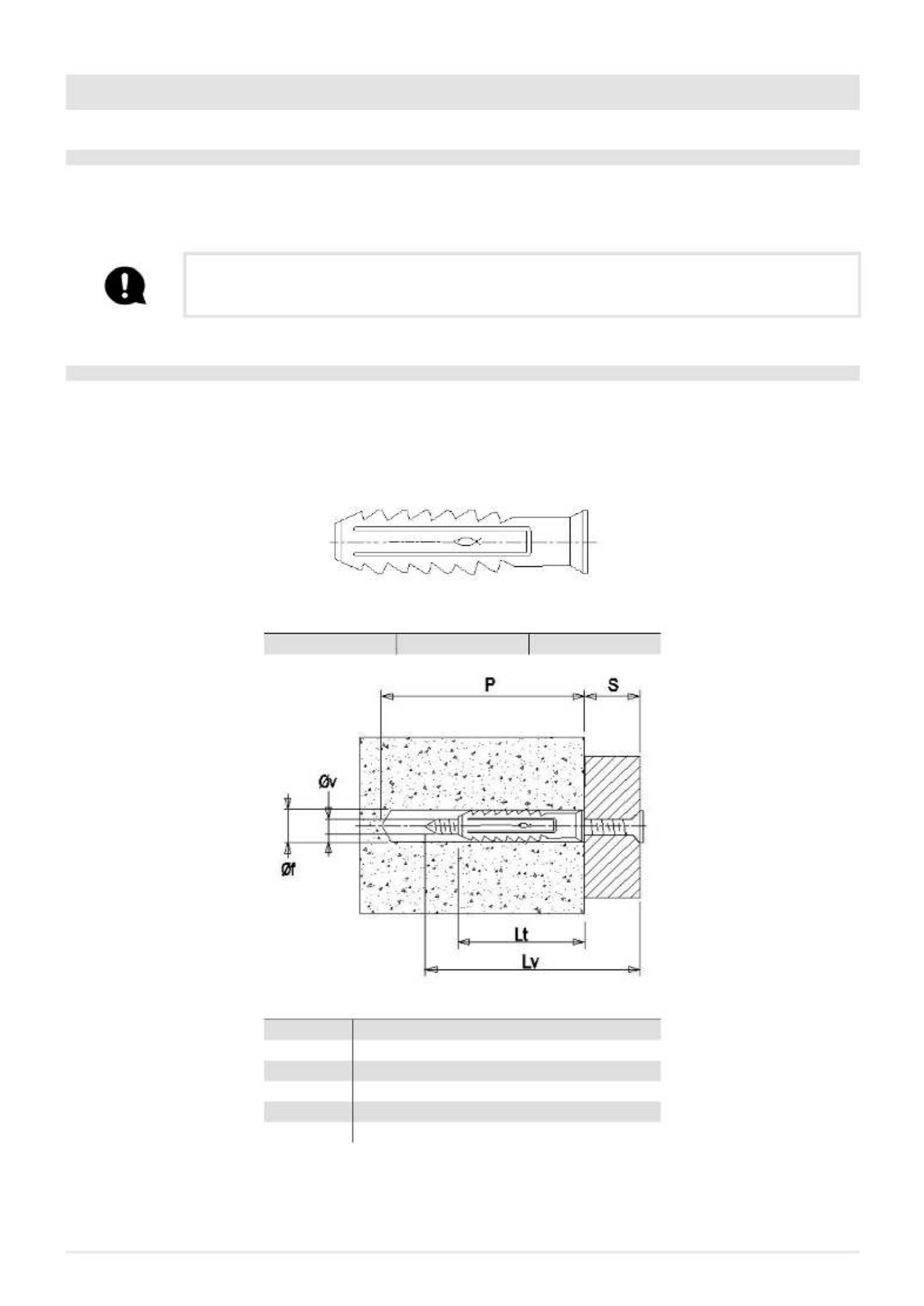
7.2 FASTENING TO AN EXISTING SURFACE - SUGGESTED CHARACTERISTICS
Installation data
The surface where the fixed part of the insert will be fastened must be in R250 kg/cm2 concrete, if the support is made of poor
material, it is advisable to use a suitable slab for fastening.
We recommend using an anchor bolt with the following characteristics:
DIMENSIONS (TYPE) DIAMETER LENGTH
SX 10 10 mm 50 mm
KEY .
LV= LT+S (SCREW LENGTH)
LT= ANCHOR BOLT LENGTH
S= MAXIMUM THICKNESS OF OBJECT BEING FASTENED
ØF = DRILL BIT DIAMETER
P= MINIMUM HOLE DEPTH
ØV = SCREW DIAMETER

SATURNO
18
TYPE Lt (anchor bolt
length) Screw Ø V x Lv P (Minimum Hole
depth)
Øf (drill bit diame-
ter)
S (Max Object
thickness)
LH 10 50 mm 8x60 mm 70 mm 10 mm 10 mm
Fastening to an existing surface
POSITION DESCRIPTION
A FIXED INSERT PART
U EXISTING SURFACE
t ANCHOER BOLTS (SEE PREVIOUS PAGE)
For installation on an existing surface, ensure there is a thickness of at least 17 mm between the fixed wall “A” and
the existing surface “U”, and fix the insert and surface using plugs “t” as shown on the previous page. Make sure
everything is level.
7.3 FASTENING TO THE HORIZONTAL SUPPORT
Place the base in the desired position (after mounting it as explained in the instructions attached to the accessory) and adjust the
height by using the feet (from a min. of 500 mm to a max. of 650 mm).
Make sure there is a power socket behind the pedestal so that the plug is accessible after the unit has been installed. Connect the
smoke outlet and make the air inlets.
It is mandatory to fasten the support to the floor with anchor bolts and 8 mm diameter screws that will ensure stability of the
product. Take the sliding base and fasten it with the support bracket. The support is already provided with bracket “P” for other
types of product. Do not mount the bracket “P” supplied in the support pack but use the one provided with the insert.

19
SATURNO
Take the movable part off the insert and connect the fixed part “A” to the support “S” with the bracket “T” and screws “k” provided.
8 MINIMUM DISTANCES SATURNO
It is recommended to install the stove detached from any walls and/or furniture, with a minimum clearance to allow effective
aeration of the appliance and a good distribution of heat in the room. Comply with the distances from flammable or heat-sensitive
objects (sofas, furniture, wood panelling, etc.) as specified below. The frontal distance from flammable materials must be at least
as specified in the product’s technical data table.
If there are particularly delicate objects such as furniture, curtains or sofas, increase the stove distance accordingly.
If the floor is made of wood, it is recommended to fit a floor protection sheet in compliance with the standards
in force in the country of installation.

21
SATURNO
9 SATURNO INSERTION HOLE
The hole to be made on the wall is 900*715 mm. These measurements allow the frame to cover the gap that remains between
the product and the hole and also allow the product to be removed if maintenance needs to be performed and/or parts replaced.
DO NOT USE THE DEVICE WITHOUT SUITABLE CASING, the product must be cased in a specific
plasterboard/wall structure.
MCZ is not liable for damage to people or property due to incorrect connections or misuse of
the device.
10 EXAMPLE OF PLACEMENT AT A 90° ANGLE

SATURNO
22
11 EXAMPLE OF PLACEMENT AT A 45° ANGLE
12 PELLET LOADING CHUTE ASSEMBLY
Another choice to be made before placing the product is to define which side to install the chute on for loading the fuel. The pellet
loader is delivered with two clamps, the connection pipe and the slide with a small hatch, all inside the same packaging of the
VIVO 90 HYDRO insert. The chute may be mounted on the right side, on the left side or at the front.
It is obligatory to shorten the connection pipe, depending on positioning (side or front), so
that it is properly taut and at a minimum angle with respect to the horizontal. This operation
is required for pellet descent. Before installing the cladding perform a fuel loading test to
ensure it descends correctly towards the hopper. It is obligatory to correctly insulate the pipe
in case it is fitted on the left side where the smoke exhaust is. The manufacturer disclaims all
liability in the event of failure to comply with the above warning. Fire hazard!!
Steps to assemble the chute.
Take the pellet loader unit out of the packaging:
• fix the pipe “A” to the insert with a clamp “f”
• fix the pipe “A” with a clamp “m” to the loader unit with door “C”

23
SATURNO
13 RIGHT CHUTE SIDE ASSEMBLY SATURNO
When opting for side chute installation, the distance from the machine axis to the wall must be 68.2 cm maximum (picture on the side).
To position the chute, proceed as follows:
• Connect the pipe supplied to Vivo 80 Pellet ensuring it is rotated to the side, and fasten it with the clamp.
• Connect the pipe (in the top section) to the mouth of the hatch structure using the supplied clamps.
• Position the pipe with the hatch structure so that, when cladding is completed, it may be screwed and fixed to the wall of the
cladding on the hole made for its insertion.
To mount the outer hatch refer to the suitable paragraph, since this operation will be performed with completed cladding.
14 SMOKE OUTLET CONNECTION SATURNO
When making the hole for the passage of the smoke discharge pipe, one must take into account the possible presence of flam-
mable materials. If the hole must be made through a wooden wall or thermolabile material, the INSTALLER MUST first of all use
the appropriate wall fitting (minimum diameter 13 cm) and suitably insulate the pipe of the product that passes through it using
adequate insulating materials (1.3 - 5 cm thick with minimum thermal conductivity 0.07 W/m°K).
The same minimum distance must be applied if the pipe of the product must pass through vertical or horizontal sections near the
thermolabile wall.
It is recommended to use an insulated double-wall pipe in external sections in order to prevent condensation from forming.
The combustion chamber works in negative pressure.

SATURNO
24
Fig. 18 - Rear outlet
15 ELECTRICAL CONNECTION SATURNO
15.1 ELECTRICAL CONNECTION SATURNO
All electrical connections must be connected by qualified personnel in compliance with laws in force in each
Country; using suitable equipment and following the diagram provided in this booklet. All operations must be
performed with the 230V 50 Hz mains supply cable disconnected.
MCZ is not liable for damage to people or property due to incorrect connections or misuse of the device.
Perform the installation following the National safety regulations in force.
Make sure a suitable earthing line is available.
Check that the voltage and frequency of the electric power supply meet requirements (230Vac 50Hz)
First connect the power cable to the back of the stove and then to a wall socket.
It is recommended to disconnect the power cable when the stove is not used.
Fig. 19 - ELECTRICAL CONNECTION

25
SATURNO
The cable must never come into contact with the smoke exhaust pipe or any other part of the stove. The power
outlet must be external to the plasterboard / wall structure recess, in an accessible position and clearly visible
by the maintenance technician.
STOVE POWER SUPPLY SATURNO
Connect the power cable to the back of the stove and then to a wall socket. The stove is then powered.
There is a fuse box also in the switch block next to the power socket. Open this compartment by simply lifting the cover, using
a screwdriver as a lever from inside the power outlet compartment. Inside there are two fuses (5x20 mm T delayed / 3.15 A 250
V), which may need to be replaced if the stove is not powered (e.g. the control panel display does not light up) - operation to be
implemented by an authorised and skilled technician.
ATTENTION!
All cleaning and / or replacement of parts must be carried out with the electric plug disconnected. Disconnect
the product from the 230V power supply before performing any maintenance operations. If the cable is da-
maged, replace it.
16 PLUMBING CONNECTION
16.1 PLUMBING SYSTEM CONNECTION
IMPORTANT!
If installation of the product involves interaction with another, pre-existing system complete with heating
equipment (gas boiler, methane boiler, diesel boiler, etc.), contact qualified personnel, who subsequently will
be responsible for conformity of the system in compliance with the applicable law in force.
The Company declines all responsibility for damage to persons or things in the event of failed or incorrect
operation, if the aforementioned warnings are not complied with.
IMPORTANT!
WE STRONGLY RECOMMEND WASHING THE ENTIRE SYSTEM BEFORE CONNECTING THE STOVE IN ORDER TO RE-
MOVE RESIDUE AND BUILD-UPS.
Always install gate valves upstream of the stove to isolate it from the hydraulic system should it be necessary
to move it for routine and/or special maintenance. Connect the stove using flexible hoses so as not to excessi-
vely bind the stove to the system and to allow it to be moved slightly.
The pressure discharge valve must always be connected to a water discharge pipe. The pipe must be suitable
to withstand the high water temperature and pressure.

SATURNO
26
16.2 CONNECTION DIAGRAM SATURNO
Fig. 20 - Connection diagram SATURNO
LEGEND Fig. 10
A1 3/4”M heating water delivery
A2 3/4”M heating water return
A3 System filling 1/2”
A4 System outlet 1/4”M (see image on next page)
16.3 3 BAR DISCHARGE VALVE SATURNO
The safety valve that can be inspected is found on the back of the stove, under the pump. It is MANDATORY to connect the safety
drain to a rubber pipe that can withstand a temperature of 110°C and that reaches the outside for any water outlet. The rubber
fitting is not supplied with the boiler but may be supplied with spare part code 41501899900 (contact the MCZ GROUP Service)
The manufacturer of the appliance is not liable for any flooding caused by the safety valves being triggered
if these have not been joined properly to the outside of the product and to a proper collection and evacuation
system.

27
SATURNO
Fig. 21 - Discharge valve
LEGEND Fig. 21
A4 3 bar CE PN10, TMAX 110°C safety valve
A4 ATTENTION: 110°C !!
16.4 WASHING THE SYSTEM
The connections must be easy to disconnect via pipe unions with swivel fittings.
Install suitable gate valves on the heating system pipes. A safety valve must be installed on the system.
To protect the heating system from harmful corrosion, build-ups or deposits, it is extremely important before installing the ap-
pliance to wash the system in compliance with the UNI 8065 standard (water treatment in heating systems for domestic use),
using appropriate products.
The use of FERNOX PROTECTOR F1 (available at our authorised centres) product is recommended, this provides long-term protec-
tion of heating systems against corrosion and calcium build-up. It prevents the corrosion of the metal parts of the appliance, i.e.
the ferrous metals, copper and copper and aluminium alloys. It also reduces the noise produced by the boiler. Refer to the instruc-
tions on the product. Cleaning should be performed by a qualified technician.
We also recommend the use of FERNOX CLEANER F3 and LEAK SEALER F4, always available from our authorised distribution centres.
FERNOX F3 is a neutral product for rapid and efficient cleaning of heating appliances. It has been designed to eliminate residues,
oily deposits and incrustations from existing appliances of all ages. It can help restore the heating efficiency of the boiler and
reduce the noise it generates.
FERNOX F4 is intended to be used with all heating appliances to seal micro fractures that cause small and inaccessible leaks.
Produkt Specifikationer
| Mærke: | Cadel |
| Kategori: | Komfur |
| Model: | Saturno 16 |
Har du brug for hjælp?
Hvis du har brug for hjælp til Cadel Saturno 16 stil et spørgsmål nedenfor, og andre brugere vil svare dig
Komfur Cadel Manualer

9 Februar 2025
9 Februar 2025
9 Februar 2025
26 December 2024
26 December 2024
26 December 2024
26 December 2024
26 December 2024
26 December 2024
26 December 2024
Komfur Manualer
- Komfur DeLonghi
- Komfur Sinbo
- Komfur Ikea
- Komfur Bosch
- Komfur SilverCrest
- Komfur PKM
- Komfur Gram
- Komfur Sencor
- Komfur EasyMaxx
- Komfur Zibro
- Komfur Wolkenstein
- Komfur Siemens
- Komfur Day
- Komfur Samsung
- Komfur Scandomestic
- Komfur Wilfa
- Komfur GE
- Komfur Breville
- Komfur Zanussi
- Komfur Cylinda
- Komfur Panasonic
- Komfur Candy
- Komfur Fisher & Paykel
- Komfur Gorenje
- Komfur Tectro
- Komfur Husqvarna
- Komfur VOX
- Komfur Miele
- Komfur Silverline
- Komfur Blomberg
- Komfur Caso
- Komfur Concept
- Komfur Steba
- Komfur Teka
- Komfur Rommelsbacher
- Komfur OK
- Komfur LG
- Komfur AEG
- Komfur Electrolux
- Komfur Thetford
- Komfur Bauknecht
- Komfur Elica
- Komfur Voss-Electrolux
- Komfur Whirlpool
- Komfur Vestfrost
- Komfur Sharp
- Komfur Hotpoint
- Komfur Dacor
- Komfur Melissa
- Komfur Atag
- Komfur ARGO
- Komfur Kenwood
- Komfur Omega
- Komfur Qlima
- Komfur Hoover
- Komfur Korona
- Komfur Arçelik
- Komfur Junker
- Komfur JennAir
- Komfur Soler & Palau
- Komfur Aduro
- Komfur Grundig
- Komfur Falmec
- Komfur Progress
- Komfur Presto
- Komfur De Dietrich
- Komfur Witt
- Komfur Indesit
- Komfur GYS
- Komfur Hwam
- Komfur Hotpoint Ariston
- Komfur Ernesto
- Komfur Livoo
- Komfur Klarstein
- Komfur Güde
- Komfur Ardo
- Komfur Furrion
- Komfur Etna
- Komfur Buderus
- Komfur Tefal
- Komfur Infiniton
- Komfur Trisa
- Komfur Princess
- Komfur Matsui
- Komfur Biltema
- Komfur Nedis
- Komfur Emerio
- Komfur Severin
- Komfur Scholtès
- Komfur Hansa
- Komfur Logik
- Komfur Hendi
- Komfur Bartscher
- Komfur Sauber
- Komfur Westinghouse
- Komfur Ilve
- Komfur Eico
- Komfur Element
- Komfur Thomson
- Komfur Constructa
- Komfur Hyundai
- Komfur Proctor Silex
- Komfur Imetec
- Komfur Hisense
- Komfur TriStar
- Komfur Clas Ohlson
- Komfur Brandt
- Komfur Animo
- Komfur Trumatic
- Komfur Airforce
- Komfur Parkside
- Komfur Adler
- Komfur Black And Decker
- Komfur Dometic
- Komfur Mestic
- Komfur Outwell
- Komfur Mio
- Komfur Eurom
- Komfur Trotec
- Komfur Blaupunkt
- Komfur Einhell
- Komfur Tomado
- Komfur AEG-Electrolux
- Komfur Asko
- Komfur Atlas
- Komfur Becken
- Komfur BEKO
- Komfur Elvita
- Komfur Gaggenau
- Komfur Iberna
- Komfur Küppersbusch
- Komfur Leonard
- Komfur Neff
- Komfur Privileg
- Komfur Sandstrøm
- Komfur Smeg
- Komfur Honeywell
- Komfur Alpina
- Komfur Clatronic
- Komfur Quigg
- Komfur Buffalo
- Komfur Proficook
- Komfur Rowenta
- Komfur Morsø
- Komfur Ariston Thermo
- Komfur Fagor
- Komfur Haier
- Komfur Cambridge
- Komfur König
- Komfur Truma
- Komfur Bomann
- Komfur Russell Hobbs
- Komfur Ariete
- Komfur Elro
- Komfur KitchenAid
- Komfur Zelmer
- Komfur Rosieres
- Komfur Boretti
- Komfur Vivax
- Komfur Thermex
- Komfur Duracraft
- Komfur EWT
- Komfur Kero
- Komfur Powerfix
- Komfur Crosley
- Komfur Amana
- Komfur Amica
- Komfur Voss
- Komfur Coleman
- Komfur KKT Kolbe
- Komfur Tesy
- Komfur Wolf
- Komfur Dimplex
- Komfur Finlux
- Komfur Telefunken
- Komfur Micromaxx
- Komfur Kernau
- Komfur Tripp Lite
- Komfur Bertazzoni
- Komfur Caple
- Komfur Zerowatt
- Komfur Mercury
- Komfur Primo
- Komfur Lervia
- Komfur Orbegozo
- Komfur Viking
- Komfur Malmbergs
- Komfur CaterChef
- Komfur Franke
- Komfur Cadac
- Komfur Salter
- Komfur Taurus
- Komfur Veripart
- Komfur Zenith
- Komfur Faber
- Komfur Balay
- Komfur Cata
- Komfur Exquisit
- Komfur Falcon
- Komfur Pelgrim
- Komfur Elba
- Komfur Faure
- Komfur Juno
- Komfur Nodor
- Komfur Stoves
- Komfur Schneider
- Komfur MPM
- Komfur Profilo
- Komfur Basetech
- Komfur Toyotomi
- Komfur Tesla
- Komfur Hanseatic
- Komfur G3 Ferrari
- Komfur Thor
- Komfur V-Zug
- Komfur Maytag
- Komfur Domo
- Komfur Mellerware
- Komfur Mill
- Komfur Jøtul
- Komfur Ferroli
- Komfur Xblitz
- Komfur Atlantic
- Komfur Perel
- Komfur La Nordica
- Komfur Saro
- Komfur Bush
- Komfur Hamilton Beach
- Komfur Ambiano
- Komfur Olimpia Splendid
- Komfur Unold
- Komfur Aspes
- Komfur Bellini
- Komfur Scancool
- Komfur Zibro Kamin
- Komfur Nevir
- Komfur Nextbase
- Komfur Techwood
- Komfur Ursus Trotter
- Komfur Harvia
- Komfur Blumfeldt
- Komfur Inventum
- Komfur Altech
- Komfur Edilkamin
- Komfur Oceanic
- Komfur Fakir
- Komfur Swan
- Komfur Khind
- Komfur Midea
- Komfur Napoleon
- Komfur CDA
- Komfur Frigidaire
- Komfur Bimar
- Komfur Ardes
- Komfur Suntec
- Komfur Esatto
- Komfur SVAN
- Komfur Everglades
- Komfur Danby
- Komfur Sogo
- Komfur RCA
- Komfur Koenic
- Komfur Scarlett
- Komfur Izzy
- Komfur Currys Essentials
- Komfur Cotech
- Komfur Lofra
- Komfur ECG
- Komfur Nova
- Komfur Saturn
- Komfur Eurochef
- Komfur Trebs
- Komfur Wamsler
- Komfur Eldom
- Komfur Proline
- Komfur Waves
- Komfur Termozeta
- Komfur OneConcept
- Komfur Invicta
- Komfur Just Fire
- Komfur Nobo
- Komfur Brandson
- Komfur Cola
- Komfur Ecoteck
- Komfur Bella
- Komfur Orion
- Komfur Duux
- Komfur Stiebel Eltron
- Komfur Kalorik
- Komfur Gemini
- Komfur Cecotec
- Komfur Rinnai
- Komfur Alde
- Komfur Solac
- Komfur Royal Catering
- Komfur Anslut
- Komfur MSR
- Komfur Ravelli
- Komfur Efbe-Schott
- Komfur Baumatic
- Komfur Barazza
- Komfur Palazzetti
- Komfur Norsk Kleber
- Komfur Beper
- Komfur Meireles
- Komfur Haas+Sohn
- Komfur Supra
- Komfur Kenmore
- Komfur Avanti
- Komfur Continental Edison
- Komfur Cookology
- Komfur Corbero
- Komfur Artusi
- Komfur Aurora
- Komfur La Germania
- Komfur Orima
- Komfur Magic Chef
- Komfur Lamona
- Komfur Bestron
- Komfur Philco
- Komfur Zanussi-Electrolux
- Komfur Novy
- Komfur Classique
- Komfur Fuave
- Komfur Kunft
- Komfur Euro Appliances
- Komfur Fuxtec
- Komfur Summit
- Komfur Kogan
- Komfur LERAN
- Komfur Coyote
- Komfur Ravanson
- Komfur Matrix
- Komfur Fulgor Milano
- Komfur BLANCO
- Komfur Airlux
- Komfur Insignia
- Komfur Consul
- Komfur Jocel
- Komfur Heller
- Komfur Signature
- Komfur Ufesa
- Komfur Manta
- Komfur Vornado
- Komfur Vitrokitchen
- Komfur Campart
- Komfur Orava
- Komfur Kaiser
- Komfur Arctic Cooling
- Komfur Linarie
- Komfur Nutrichef
- Komfur Thorma
- Komfur ARC
- Komfur Chef
- Komfur Ellrona
- Komfur Atosa
- Komfur Profile
- Komfur Kluge
- Komfur Leisure
- Komfur AKO
- Komfur Artel
- Komfur Toolland
- Komfur Salton
- Komfur Rika
- Komfur Jata
- Komfur BlueStar
- Komfur Monogram
- Komfur Climastar
- Komfur Nestor Martin
- Komfur Heinner
- Komfur Nabo
- Komfur Rangemaster
- Komfur Beha
- Komfur Well Straler
- Komfur Piazzetta
- Komfur Jenn-Air
- Komfur Freggia
- Komfur Listo
- Komfur Edesa
- Komfur EAS Electric
- Komfur Alpatec
- Komfur Blaze
- Komfur Porter & Charles
- Komfur M-System
- Komfur Dovre
- Komfur Mx Onda
- Komfur Igenix
- Komfur Essentiel B
- Komfur MaxxHome
- Komfur Duro
- Komfur AWB
- Komfur Café
- Komfur Equator
- Komfur Superior
- Komfur Radson
- Komfur Argoclima
- Komfur ZLine
- Komfur Jaga
- Komfur Coline
- Komfur Bora
- Komfur Imarflex
- Komfur Wëasy
- Komfur Extraflame
- Komfur Tayosan
- Komfur Thermor
- Komfur Schmid
- Komfur Livington
- Komfur Cuckoo
- Komfur Livin Flame
- Komfur Gutfels
- Komfur Max Blank
- Komfur Spartherm
- Komfur El Fuego
- Komfur Opera
- Komfur Ecoforest
- Komfur Voltomat Heating
- Komfur Qlima - Zibro
- Komfur Mayer
- Komfur Veito
- Komfur Oranier
- Komfur Bocal
- Komfur Haas-Sohn
- Komfur FlumenFire
- Komfur Austroflamm
- Komfur Thermorossi
- Komfur Saey
- Komfur Eva Calor
- Komfur Nordic Fire
- Komfur Flam
- Komfur Kabola
- Komfur Ganz
- Komfur Olympia Fires
- Komfur Elements
- Komfur Wanders
- Komfur Merkloos
- Komfur Kago
- Komfur JAcobus
- Komfur Efel
- Komfur Hartig Helling
- Komfur Kerosun
- Komfur Eledi
- Komfur Olsberg
- Komfur Econo-Heat
- Komfur Kompernass
- Komfur Stover
- Komfur Cecilware
- Komfur Laxevaags
- Komfur Vulcan
- Komfur Norflam
- Komfur Rocal
- Komfur MCZ
- Komfur Rais
- Komfur Micronova
- Komfur Global
- Komfur Wiking
- Komfur DRU
- Komfur Capital
- Komfur PVG
- Komfur Prem-i-air
- Komfur PTC
- Komfur K&H
- Komfur Bild
- Komfur Burley
- Komfur Gimeg
- Komfur Kruger
- Komfur Acros
- Komfur Cosmo
- Komfur Ulma
- Komfur Panadero
- Komfur Ciarra
- Komfur Justus
- Komfur Enkho
- Komfur Xeoos
- Komfur Modena
- Komfur Hark
- Komfur Yellow Profiline
- Komfur Horus
- Komfur Migros
- Komfur Zen Fires
- Komfur Harman
- Komfur Rowi
- Komfur Emilia
- Komfur Webasto
- Komfur Scan
- Komfur Mr Safe
- Komfur Reny
- Komfur Hearthstone
- Komfur Kratki
- Komfur Flandria
- Komfur Barbas
- Komfur Dik Geurts
- Komfur Bromic
- Komfur MSW
- Komfur ATTACK
- Komfur Toyoset
- Komfur Thermocet
- Komfur Surdiac
- Komfur Catler
- Komfur Gasmate
- Komfur Aspire By Hestan
- Komfur Electroline
- Komfur Pando
- Komfur CEEM
- Komfur Master Kitchen
- Komfur Uniprodo
- Komfur PITSOS
- Komfur Yamazen
- Komfur Fratelli
- Komfur Bröhn
Nyeste Komfur Manualer

9 April 2025
9 April 2025
8 April 2025
8 April 2025
8 April 2025

7 April 2025
7 April 2025
7 April 2025
7 April 2025
7 April 2025