Colormetrics V1500 Manual
Colormetrics
Boks
V1500
Læs nedenfor 📖 manual på dansk for Colormetrics V1500 (68 sider) i kategorien Boks. Denne guide var nyttig for 25 personer og blev bedømt med 4.5 stjerner i gennemsnit af 2 brugere
Side 1/68

1
www.colormetrics.info metrics V1500Color
Errors excepted; subject to change www.colormetrics.info
V1500
User Manual
Version 1.0

2www.colormetrics.infoColormetrics V1500
Copyright 2018 Colormetrics All Rights Reserved.
This manual, software and firmware described in it are copyrighted by their respective owners and
protected under the laws of the Universal Copyright Convention. You may not reproduce, transmit,
transcribe, store in a retrieval system, or translate into any language, in any form or by any means,
electronic, mechanical, magnetic, optical, chemical, biological, molecular,m manual, or otherwise,
any part of this publication without the express written permission of the publisher.
All products and trade names described within are mentioned for identification purpose only. No
affiliation with or endorsement of the manufacturer is made or implied. Product names and brands
appearing in this manual are registered trademarks of their respective companies.
The information published herein has been checked for accuracy as of publishing time. Norepre-
sentation or warranties regarding the fitness of this document for any use are made orimplied by the
publisher. We reserve the right to revise this document or make changes in the specifications of the
product described therein at any time without notice and without obligation to notify any person of
such revision or change.
COPYRIGHT

3
www.colormetrics.info metrics V1500Color
SAFETY INSTRUCTIONS
1. Read these instructions carefully. Keep these instructions for future reference.
2. Please disconnect this device from AC outlet before cleaning. Do not use liquid or spray
detergent for cleaning. Use moisture sheet or cloth for cleaning.
3. Please keep your device safe from high levels of humidity.
4. Install the device and its driver on a surface plate. Any tilt plate might cause damage.
5. Do not place anything over the power cord. And avoid people from stepping on it
6. Please be aware cautious note or warnings on the device.
7. If the device will not be used for a long time, please unplug the power cord to avoid damages by
transient overvoltage.
8. Never pour any liquid into the device; this could cause fire or electrical shock.
9. If one of the following situations happens, get the device checked by a service personnel:
a. The power cord or plug is damaged.
b. Liquid has penetrated into the device.
c. The device has been exposed to moisture.
d. The device does not work well or you cannot get it work according to user manual.
e. The device has dropped and damaged.
10. Do not leave this device in an environment unconditioned, storage temperature below -20°C or
above 60°C, it may damage the device.
11. Unplug the power cord when doing any service or adding optional kits.
Lithium Battery Caution:
1. 1. Danger of explosion can happen if the battery is incorrectly replaced. Replace only the
original or equivalent type recommended by the manufacture. Dispose used batteries according
to the manufacture’s instructions.
2. Do not remove the cover, and ensure no user serviceable components are inside. Take the unit
to the service center for service and repair.

4www.colormetrics.infoColormetrics V1500
CE Notice
This device complies with the requirements of the CE directive.
WEEE Notice
This appliance is labeled in accordance with European Directive 2002/96/EC concerning waste
electrical and electronic equipment (WEEE). The Directive determines the framework for the
return and recycling of used appliances as applicable throughout the European Union. This
label is applied to various products to indicate that the product is not to be thrown away, but
rather reclaimed upon end of life per this Directive.

5
www.colormetrics.info metrics V1500Color
1. Packing List 6
1-1 Standard Accessories 6
1-2 Optional Accessories 6
2. System View 7
2-1 Rear View 7
2-2 Side View 7
2-3 Front View 7
2-4 Back View 8
2-5 Specication 9
2-6 Internal Layout 10
3. Pin Denition 11
4. System Assembly & Disassembly 17
4-1 HDD 17
4-2 Memory 18
4-3 MSR 19
4-4 VFD 20
4-5 The 2nd Display 21
4-6 WI-FI 22
5. Device Driver Installation 23
5-1 Resistive Type Touch Panel & P-CAP 23
5-2 MagStripe Card Reader Conguration Utility 29
5-3 RFID 41
5-4 Conguration Utility of i-Button Reader 47
5-5 VFD 52
6. BIOS/Utility Setup 59
6-1 Advanced 59
6-2 Security 64
6-3 Power 65
6-4 Boot 66
6-5 Exit 67
7. LCD Surface Cleaning 68

6www.colormetrics.infoColormetrics V1500
PACKING LIST
1-2 Optional Accessories
System (with stand)
Power adapter
Power cord
Driver bank
1-1 Standard Accessories
VFD
2nd Display (8,10,)
MSR
RF-ID Leser
MSR+RF-ID
i-button
MSR+iButton
1D Scanner
2D Scanner

7
www.colormetrics.info metrics V1500Color
2-1 Rear View
2-2 Side View
2-3 Front View
Please make sure the 19V DC is plugged in the right direction before plugging in DC jack.
SYSTEM VIEW
LCD
1D / 2D Scanner
(option)

8www.colormetrics.infoColormetrics V1500
2-4 Back View
VFD / 2nd Display
(optional)
MSR / i-Button
RFID (optional)
HDD / RAM / WIFI
module(optional)
9
www.colormetrics.info metrics V1500Color
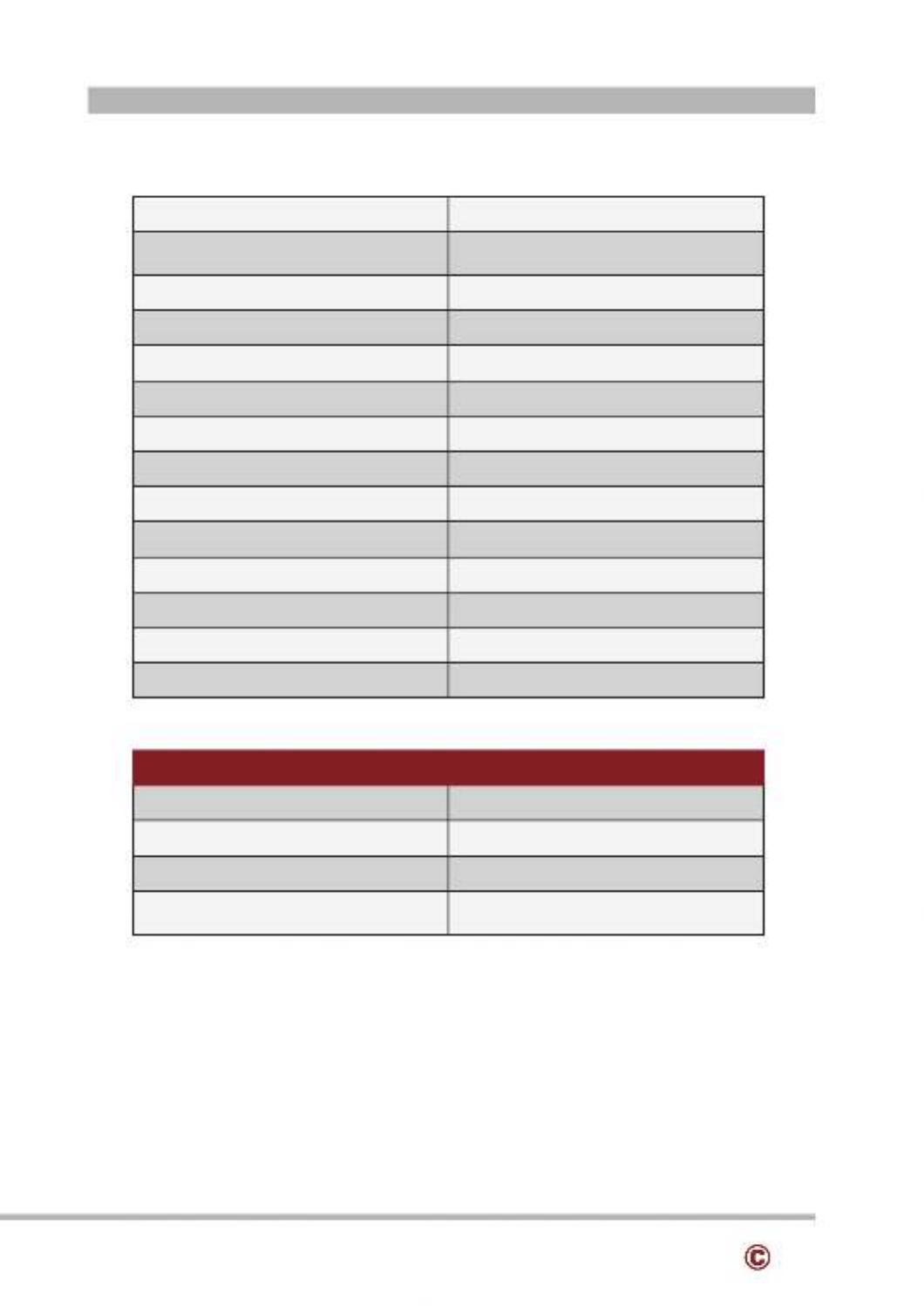
2-5 Specification
Processor Intel® Celeron J1900 Quad Core 2.0GHz
Memory One SO-DIMM socket supports DDR3L
1333 up to 8GB
Storage 2.5” SATA II HDD / SSD
Audio Line-out
Network RJ45 10/100/1000 Base-T
USB port 5x USB 2.0 / 1x USB 3.0
COM Port 3x RJ45
BIOS Insyde BIOS
Power AC 19V 90W Adaptor
Thermal Solution Fan-less
Dimension 366 (W)x 377 (H) x265 (D)mm
Operating Temperature 0°C ~ 35°C
Storage Temperature -20°C ~ 60°C
Storage Humidity 20% ~ 80%, non-condensing
Display
LCD Panel Size 15.1-inch TFT LCD (LED Backlight)
Resolution 1024*768 Pixels
Brightness 350 cd/m2
Touch Panel 5-wire Resistive Type /
Projected Capacitive Type
Note:
Intel® Celeron J1900 CPU does not support POSReady 2009

10 www.colormetrics.infoColormetrics V1500
2-6 Internal Layout

11
www.colormetrics.info metrics V1500Color
1. 2-Layer USB2.0 connector Pin Definition
No. Definition No.
Definition
1
+5V
5
+5v
2
D-
6
D-
3
D+
7
D+
4
GND
8
GND
2. 2-Layer USB3.0+2.0 connector Pin Definition
No. Definition efinitionNo. D
1
+5V
8
TX-
2 D- 9 TX+
3
D+
10
+5V
4 D-GND 11
5
RX-
12
D+
6 RX+ 13 GND
7
GND
3. LAN: RJ45 Pin Definition
No.
Definition
1 MDI0A+
2
MDI0A-
3 MDI1A+
4
MDI1A-
5 MDI2A+
6
MDI2A-
7 MDI3A+
8
MDI3A-
4. LINE- POUT JACK in Definition
No.
Definition
1 GND_AUD
2
GND_AUD
3 LINE_OUTR2
4
LINE_OUTL2
5 -JDLINE2
PIN DEFINITION

12 www.colormetrics.infoColormetrics V1500
5. VGA+USB+DC12V connector Pin Definition
No. Definition efinitionNo. D
1 DDC_CLK GND11
2 DDC_DATA RED12
3 GND GND13
4 VSYNC 14 GND
5 GND 15 +12V
6 -HSYNC 16 USB D
7 GND 17 +12V
8 BLUE 18 USB D+
9 GND 19 Reserve for VGA +5V
10 20GREEN +5V
6. VGA Pin Definition
No. Definition efinitionNo. D
1 9Red N/C
2 Green 10 GND
3 Blue N/C11
4 N/C 12 I2C DATA
5 GND HSYNC13
6 GND 14 VSYNC
7 GND 15 I2C CLK
8 GND
7. LVDS connector Pin Definition
No. Definition efinitionNo. D
1 2+3.3V +3.3V
3 4+3.3V +3.3V
5 6GND GND
7 - 8 -DATA1 DATA0
9 DATA1+ DATA0+10
11 GND GND12
13 14CLK- DATA2-
15 16CLK+ DATA2+
17 18GND GND
19 20N/C DATA3-
21 Brightness 22 DATA3+

13
www.colormetrics.info metrics V1500Color
23 BKL enable 24 GND
25
GND
26
GND
27 LED Power +12V LED Power +12V28
29
LED Power +12V
30
LED Power +12V
8. eDP connector P :in Definition
No.
Definition
No.
Definition
1 N/C GND16
2 GND 17 HotPlug Detect
3 N/C GND18
4
N/C
19
GND
5 GND GND20
6 -TxD0 21 GND
7 TxD0+ 22 BKL enable
8 GND 23 Brightness
9 AUX+ 24 N/C
10 25AUX- N/C
11 GND 26 +12V
12 +3.3V 27 +12V
13 +3.3V 28 +12V
14 29 +12VN/C
15 30GND N/C
9. DC Jack Pin Definition
No. Definition
1 +19V
2 Ground
3 +19V
10. RJ45(COM) connector Pin Definition
No. Definition
1 +5V/+12V
2 DSR#
3 GND
4 DTR#
5 RST#
6 CTS#

14 www.colormetrics.infoColormetrics V1500
7 TxD
8
RxD
11. SATA: 22-pin SATA Pin Definition
No.
Definition
No.
Definition
S1 P1GND N/C
S2
SATA_TX0_P
P2
N/C
S3 SATA_TX0_N P3 N/C
S4 P4GND GND
S5 SATA_RX0_N P5 GND
S6
SATA_RX0_P
P6
GND
S7 P7GND +5V
P8 +5V
P9 +5V
P10 GND
P11 GND
P12 GND
P13 N/C
P14 N/C
P15 N/C
12. Mini- PPCIE in Definition
No. Definition efinitionNo. D
1 #WAKE 29 GND
2 +V3.3V 30 SMB__CLK
3 N/C 31 PCIE_TX_N
4 GND 32 SMB_DATA
5 N/C 33 PCIE_TX_P
6 +1.5V 34 GND
7 CLKREQ# GND35
8 -N/C 36 USB D
9 GND N/C37
10 38N/C USB D+
11 CLK_PCIE_N 39 N/C
12 40N/C GND
13 CLK_PCIE_P 41 N/C
14 42N/C N/C

15
www.colormetrics.info metrics V1500Color
15 43GND N/C
16
N/C
44
N/C
17 45N/C N/C
18
GND
46
N/C
19 47N/C N/C
20
W_DISABLE#
48
+V1.5V
21 49GND N/C
22
RESET#
50
GND
23 51PCIE_RX_N N/C
24
+3.3V_AUX
52
+V3.3V
25 53PCIE_RX_P GND
26
GND
54
GND
27 55GND GND
28
+V1.5V
56
GND
13. Int. Speaker Pin Definition
No.
Definition
1 Left Out +
2
Left Out -
3 -Right Out
4 Right Out+
14. Touch Button for Power On/Off connector Pin Definition
No.
Definition
1 +5V Standby
2 +5V Status
3 Power On#
4 GND
15. NFC port connector Pin Definition
No. Definition
1 +5V
2 -USB D
3 USB D+
4 GND

16 www.colormetrics.infoColormetrics V1500
16. Sideward USB port connector Pin Definition
No. Definition
1 GND
2 USB D+
3 -USB D
4 +5V
5 GND
6 USB D+
7
USB D-
8 +5V
17. Front Panel function connector Pin Definition
No. Definition efinitionNo. D
1
+5V
2
+5V
3 D 4SR4# TxD5 for touch panel
5
DTR4#
6
RxD5 for touch panel
7 8RTS4# GND
9
CTS4#
10
+12V
11 TxD4 12 +5V
13
RxD4
14
+3.3V
15 16GND GND
17
+5V
18
+5V Standby
19 20USB D- +5V
21
USB D+
22
Power On#
23 24GND GND
18. RJ11(Cash Drawer) connector Pin Definition
No. Definition
1
GND
2 C/D_OPEN#
3
C/D Status
4 +12V/+24V
5
N/C
6 GND

17
www.colormetrics.info metrics V1500Color
4-1 HDD
1. Unscrew 4 screws and remove the base cover
2. Fasten HDD on HDD bracket with 2 screws
3. Install HDD with 2 screws
SYSTEM ASSEMBLY & DISASSEMBLY

18 www.colormetrics.infoColormetrics V1500
4-2 Memory
1. Put the memory into socket
19
www.colormetrics.info metrics V1500Color
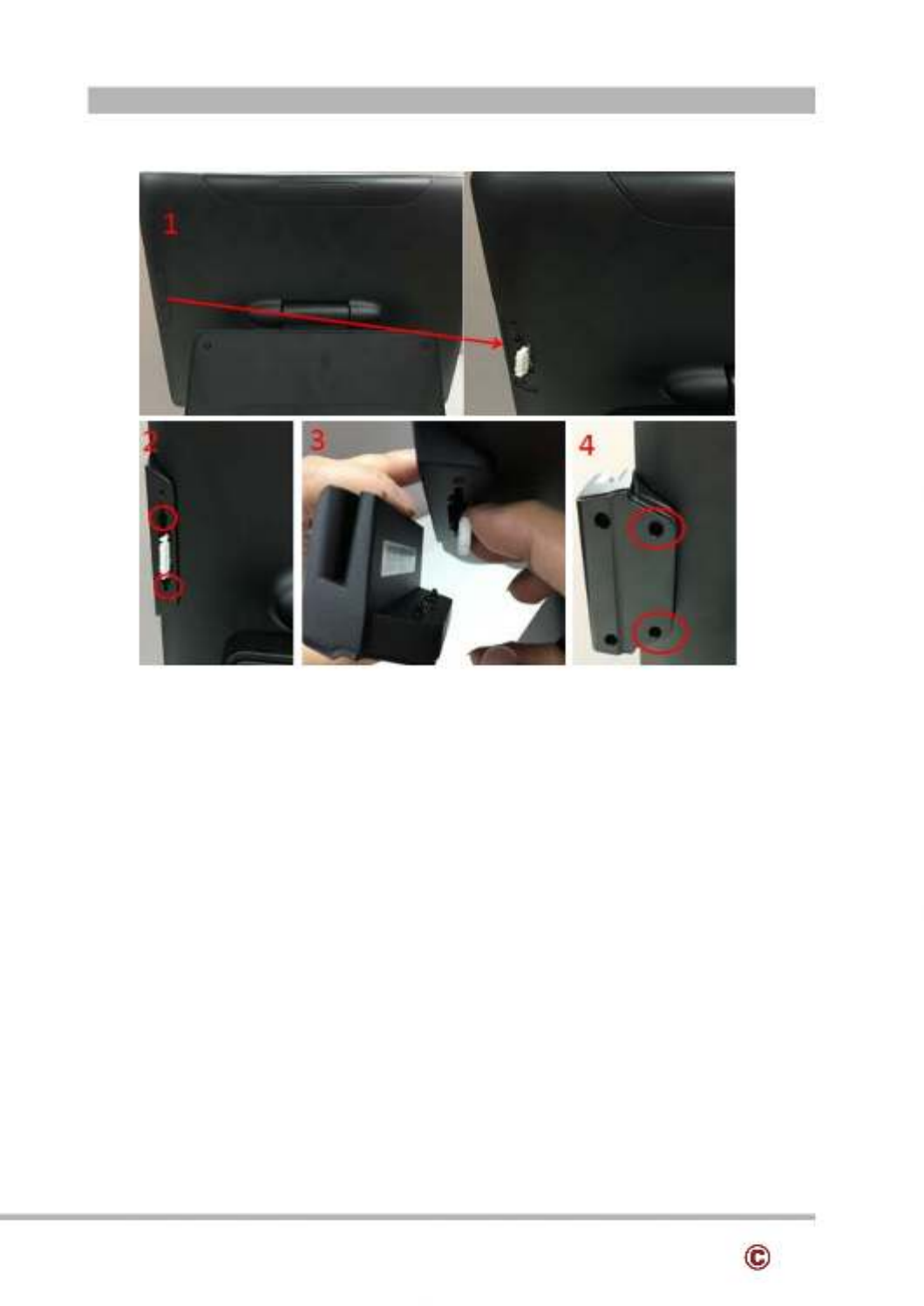
4-3 MSR
1. Remove MSR cover
2. Install MSR holder with 2 screws
3. Plug MSR cable
4. Install MSR with 2 screws
20 www.colormetrics.infoColormetrics V1500
4-4 DVF
1. Remove the Top cover
2. Plug VFD display cable
3. Install VFD with 2 screws
4. Cover the Top cover (with Hinge hole)

21
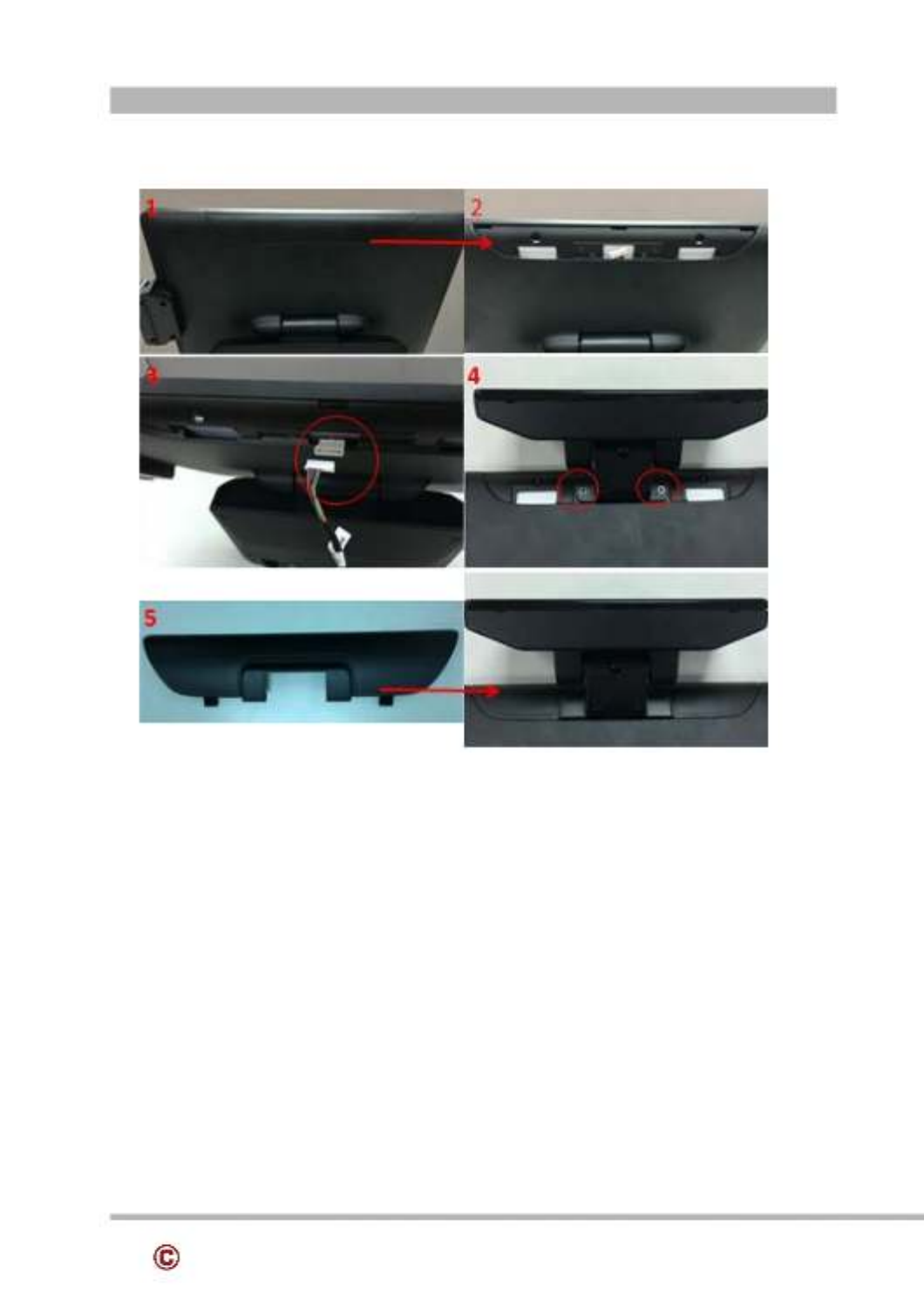
www.colormetrics.info metrics V1500Color
1. Remove the Top cover
2. 2Plug nd display (VFD) cable
3. Install 2nd display with 2 screws
4. Cover the Top cover (with Hinge hole)
4-5 The 2nd Display

22 www.colormetrics.infoColormetrics V1500
4-6 Wi-Fi
1. Put the WI- -FI module into the Mini PCIE Slot.
2. antennaConnect 2 s on Wi-Fi .( :module Notice The antenna in black should be connected
on position 1 of WI-FI module connected, and antenna in gray should be on position 2 of WI-FI
module)
3. Put Wi-Fi module into socket with 1 screw

23
www.colormetrics.info metrics V1500Color
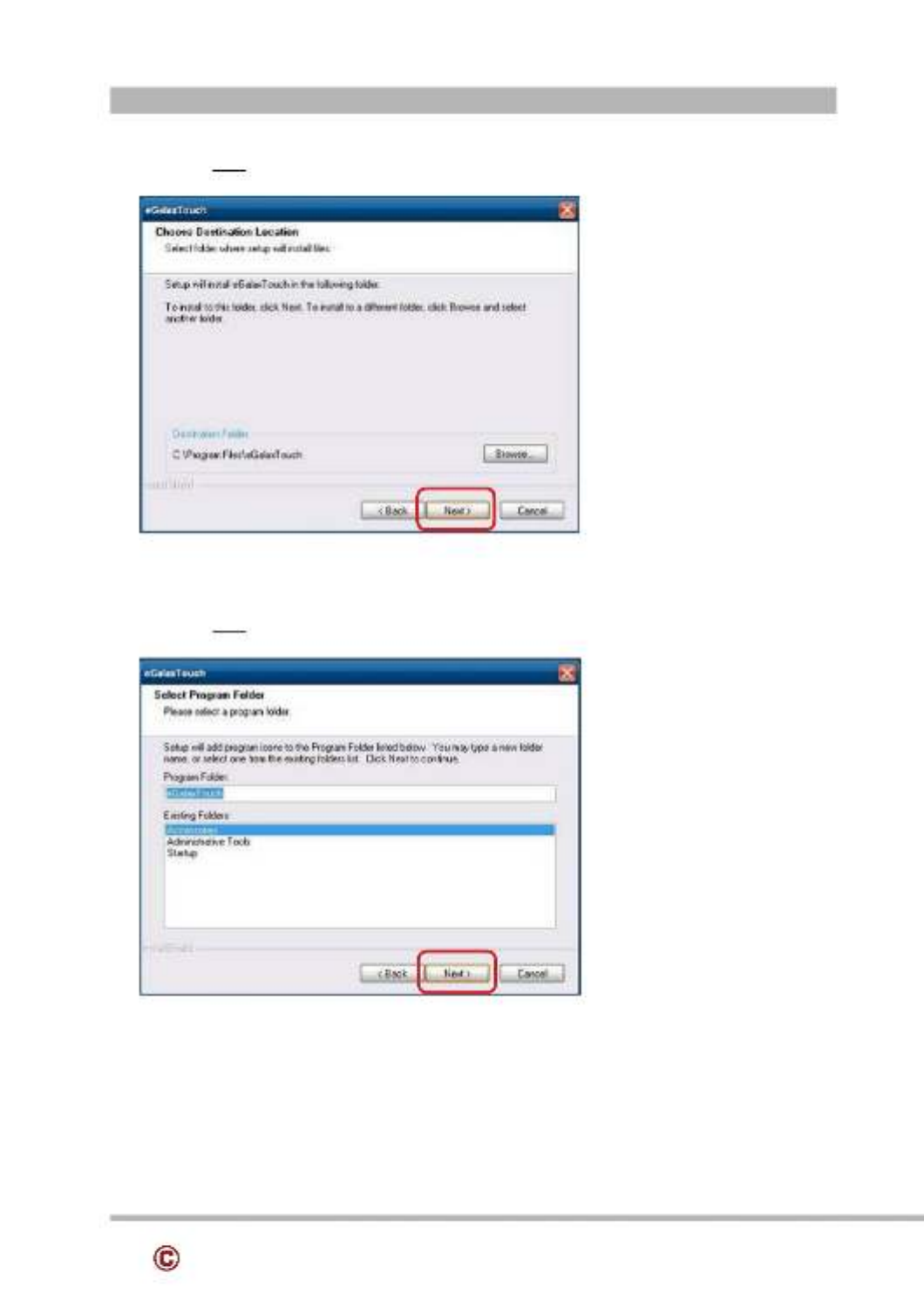
1. Click “Next”.
2. Click “Next”.
5-1. Resistive Type Touch Panel and P-CAP
DEVICE DRIVER INSTALLATION

24 www.colormetrics.infoColormetrics V1500
3. “Click Next”.
4. “ “Select None”, Click Next”.
5 Click “OK”.

25
www.colormetrics.info metrics V1500Color
6. “Select Support Multi-Monitor System”, Click “Next”.
7. “Click Next”.
26 www.colormetrics.infoColormetrics V1500
8. “Click Next”.
9. “Click Next”.

27
www.colormetrics.info metrics V1500Color
10. “Select Create a eGalaxTouch Utility shortcut on desktop”, Click “Next”.

28 www.colormetrics.infoColormetrics V1500
11. Would you do 4 point calibration now? Click “Yes”.
12. Do 4 points aligrment to match display.
13. Calibration utility.
29
www.colormetrics.info metrics V1500Color
The MagSwipe MagSwipe Configuration Utility is used to set up the output format of
Installation
Below steps guide you how to install the Utility program
Insert the setup CD
Run the 80066804-006_Magswipe_Configuration_Software_V2_1_A setup file that is
located in the Software folder of CD.
Follow the wizard to complete the installation.
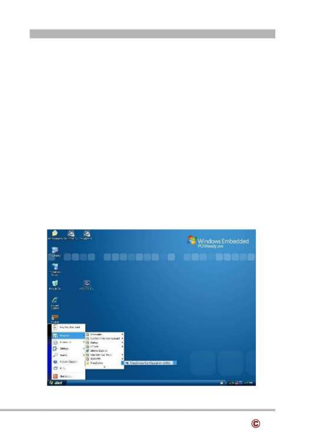
Launching Program
Below steps guide you how to load the Utility program.
From Start/Programs, click MagSwipe folder
Click MagSwipe Configuration Utility to launch the program.
5-2 wMagS ipe Card Reader Configuration Utility

30 www.colormetrics.infoColormetrics V1500
Configuration
Select Reader Interface
The reader to be configured should be connected. Select the corresponding connected reader
interface and click the Continue button

31
www.colormetrics.info metrics V1500Color
After the interface selection is made, click the button. The utility attempts to Continue
communicate with the connected reader. If successful, the Home Menu Page is displayed. The
Home Menu Page is shown below

32 www.colormetrics.infoColormetrics V1500
Change Basic Reader Setting
After selecting the appropriate interface for the reader, select one of the Home Menu Page
buttons to proceed with the Magnetic Stripe Reader (MSR) configuration process. The "Basic
Reader Settings" group defines the basic operating parameters and data output format of the
reader.
Button Definitions
Send To MSR
When all the setting parameters are selected, use the "Send To MSR..." button to send
configuration data to the reader device. When the reader has received the data correctly, the
settings take effect immediately.
Load From File
The configuration data can be loaded into the configuration utility from a file that has been
previously saved. Select this command, start a "File Open" dialog, which allows selection of
the file.

33
www.colormetrics.info metrics V1500Color
Save To File
The configuration data can be saved as a file and being used later to configure other readers.
When saving a configuration the "File Save" dialog is opened as shown below. Input a
filename and file location.
Default All
This button sets the reader with the default configuration parameters (the default factory
settings). The settings take effect immediately. The default parameters affect all reader
configurations settings.
Close
Close this dialog and return to the Home Menu Page.
34 www.colormetrics.infoColormetrics V1500
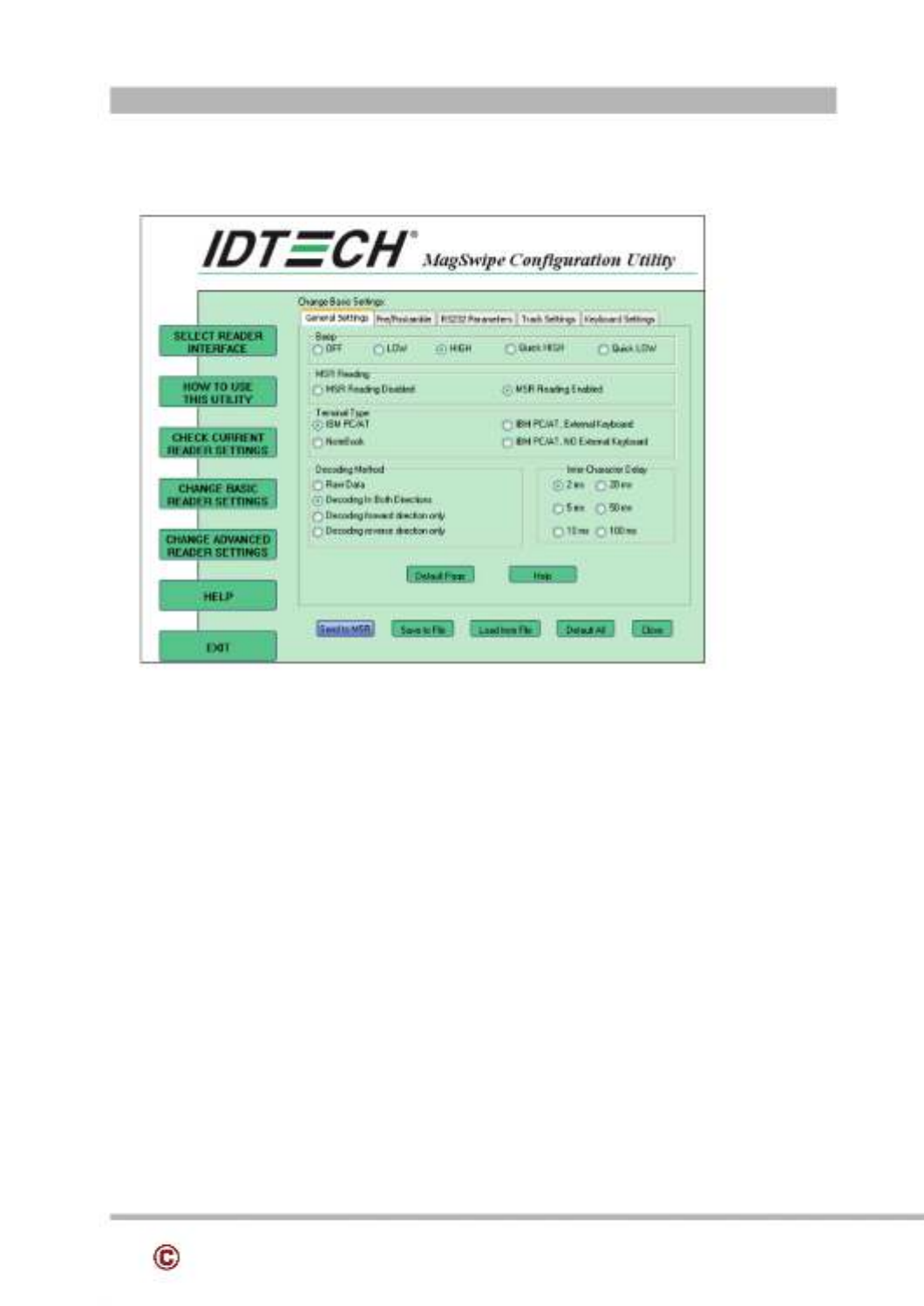
General Settings
This group of configuration settings defines the basic operating parameters of the reader.
MSR Reading
This option will turn on or off the MSR. If MSR is disabled no data is sent out to host in any
case. The default is MSR Reading Enabled.
Decoding Method Settings
This option gives four kinds of decoding methods.
Raw Data (output in both forward and reverse directions)
Decoding in Both Directions (forward and reverse reading)
Decoding in Forward Direction only (card entering slot from LED end)
Decoding in Reverse Direction only (card entering slot from end opposite LED)
With the bi directional operation, the user can swipe the card in both swipe directions and the -
data encoded on the magnetic stripe will be output. In the single swipe direction selections, the
card can only be swiped in one specified direction to read the card. The default setting will
decoding card data with the card swiped in either the forward or the reverse direction.
Produkt Specifikationer
| Mærke: | Colormetrics |
| Kategori: | Boks |
| Model: | V1500 |
Har du brug for hjælp?
Hvis du har brug for hjælp til Colormetrics V1500 stil et spørgsmål nedenfor, og andre brugere vil svare dig
Boks Colormetrics Manualer

1 September 2024
1 September 2024
1 September 2024
1 September 2024
1 September 2024
1 September 2024
1 September 2024
1 September 2024
Boks Manualer
- Boks Samsung
- Boks Miele
- Boks Sharp
- Boks HP
- Boks Toshiba
- Boks Casio
- Boks Olivetti
- Boks Zebra
- Boks Olympia
- Boks ELO
- Boks Intermec
- Boks IZettle
- Boks Newland
- Boks Vectron
- Boks Barska
- Boks Sam4S
- Boks Crestron
- Boks CUSTOM
- Boks Qian
- Boks Equip
- Boks VeriFone
- Boks Approx
- Boks Flytech
- Boks Posiflex
- Boks Cambro
- Boks AOpen
- Boks EC Line
- Boks MyPOS
Nyeste Boks Manualer
19 Februar 2025
19 Februar 2025
19 Februar 2025
3 Januar 2025
28 December 2024
28 December 2024
28 December 2024
28 December 2024
27 December 2024
27 December 2024