ECS Q87H3-M5 Manual
Læs nedenfor 📖 manual på dansk for ECS Q87H3-M5 (170 sider) i kategorien Bundkort. Denne guide var nyttig for 6 personer og blev bedømt med 4.5 stjerner i gennemsnit af 2 brugere
Side 1/170

USER GUIDE
Version:1.0
40-012-KF7101 ®


Q87H3-M5 USER MANUAL
Preface
Copyright
This publication, including all photographs, illustrations and software, is protected
under international copyright laws, with all rights reserved. Neither this manual, nor
any of the material contained herein, may be reproduced without written consent of
the author.
Version 1.0
Disclaimer
The information in this document is subject to change without notice. The manufac-
turer makes no representations or warranties with respect to the contents hereof
and specifically disclaims any implied warranties of merchantability or fitness for
any particular purpose. The manufacturer reserves the right to revise this publica-
tion and to make changes from time to time in the content hereof without obligation
of the manufacturer to notify any person of such revision or changes.
Trademark Recognition
Microsoft, MS-DOS and Windows are registered trademarks of Microsoft Corp.
MMX, Pentium, Pentium-II, Pentium-III, Celeron are registered trademarks of Intel
Corporation.
Other product names used in this manual are the properties of their respective owners
and are acknowledged.
Federal Communications Commission (FCC)
This equipment has been tested and found to comply with the limits for a Class B
digital device, pursuant to Part 15 of the FCC Rules. These limits are designed to
provide reasonable protection against harmful interference in a residential instal-
lation. This equipment generates, uses, and can radiate radio frequency energy and,
if not installed and used in accordance with the instructions, may cause harmful
interference to radio communications. However, there is no guarantee that interfer-
ence will not occur in a particular installation. If this equipment does cause harmful
interference to radio or television reception, which can be determined by turning
the equipment off and on, the user is encouraged to try to correct the interference by
one or more of the following measures:
•Reorient or relocate the receiving antenna
•Increase the separation between the equipment and the receiver
•Connect the equipment onto an outlet on a circuit different from that to
which the receiver is connected
•Consult the dealer or an experienced radio/TV technician for help
Shielded interconnect cables and a shielded AC power cable must be employed with
this equipment to ensure compliance with the pertinent RF emission limits govern-
ing this device. Changes or modifications not expressly approved by the system’s
manufacturer could void the user’s authority to operate the equipment.


ii
Q87H3-M5 USER MANUAL
Declaration of Conformity
This device complies with part 15 of the FCC rules. Operation is subject to the follow-
ing conditions:
•This device may not cause harmful interference.
•This device must accept any interference received, including interference
that may cause undesired operation.
Canadian Department of Communications
This class B digital apparatus meets all requirements of the Canadian Interference-
causing Equipment Regulations.
Cet appareil numérique de la classe B respecte toutes les exigences du Réglement
sur le matériel brouilieur du Canada.
The manual consists of the following:
Describes features of the
motherboard.
Hpage 1
Describes installation of
motherboard components.
Hpage 7
Hpage 27
Installing the Motherboard
Introducing the Motherboard
Provides information on us-
ing the BIOS Setup Utility.
Limits and methods of mesurement of radio disturbance char-
acteristics of information technology equipment
EN 55022
EN 61000-3-2 Disturbances in supply systems caused
EN 61000-3-3 Disturbances in supply systems caused by household appli-
ances and similar electrical equipment “ Voltage fluctuations”
EN 55024 Information technology equipment-Immunity characteristics-
Limits and methods of measurement
EN 60950 Safety for information technology equipment including electri-
cal business equipment
CE marking
About the Manual
This device is in conformity with the following EC/EMC directives:
Chapter 1
Chapter 2
Chapter 3
Using BIOS
Chapter 5
Trouble Shooting
Provides basic trouble
shooting tips.
page 77
H
Chapter 4 page 71
H
Intel® Matrix Storage Manager
RAID Configurations
Describes Intel® Matrix
Storage Manager RAID
Configurations.


iii
Q87H3-M5 USER MANUAL
Chapter 2 7
Installing the Motherboard 7
Safety Precautions..............................................................................7
Installing the Motherboard in a Chassis.......................................7
Checking Jumper Settings..................................................................8
Installing Hardware...........................................................................9
Installing the Processor............................................................9
Installing the CPU Cooler........................................................11
Installing Memory Modules...................................................12
Installing Add-on Cards..........................................................14
Connecting Optional Devices.................................................16
Installing a SATA Hard Drive...................................................22
Connecting Case Components........................................................23
Front Panel Header................................................................26
TABLE OF CONTENTS
Preface i
Chapter 1 1
Introducing the Motherboard 1
Introduction...........................................................................................1
Pakage Contents..................................................................................1
Specifications......................................................................................2
Motherboard Components................................................................4
I/O Ports...............................................................................................6
Chapter 3 27
Using BIOS 27
About the Setup Utility......................................................................27
The Standard Configuration........................ ...........................27
Entering the Setup Utility.......................................................27
Using BIOS.........................................................................................28
BIOS Navigation Keys..............................................................29
Main Menu.............................................................................30
Advanced Menu......................................................................31
Chipset Menu............................................................................51
M.I.B.X Menu............................................................................58
Boot Menu...............................................................................66
Security Menu..........................................................................67
Exit Menu...............................................................................68
Updating the BIOS......................................................................69


iv
Q87H3-M5 USER MANUAL
Chapter 5 77
Trouble Shooting 77
Start up problems during assembly..............................................77
Start up problems after prolong use............................................78
Maintenance and care tips..............................................................78
Basic Troubleshooting Flowchart.....................................................79
Chapter 4 71
Intel®®®®® Matrix Storage Manager RAID Configuration 71
Before creating a RAID set..............................................................71
Entering Intel® Matrix Storage Manager RAID BIOS utility.....72
Creating a RAID set...........................................................................73
Deleting a RAID set...........................................................................75
Reseting disks to Non-RAID............................................................76
Exiting Setup.....................................................................................76


1
Q87H3-M5
USER MANUAL
Chapter 1
Chapter 1
Introducing the Motherboard
Introduction
Your motherboard package ships with the following items:
Package Contents
Q87H3-M5 Motherboard
Quick Installation Guide
User Manual
DVD
I/O Shield
2 SATA Cables
The package contents above are for reference only, please take the actual
package items as standard.
Thank you for choosing the Q87H3-M5 motherboard. This motherboard is a high per-
formance, enhanced function motherboard designed to support the LGA1150 socket
for Intel 4th Generation CoreTM Family processors for high-end business or personal
desktop markets.
This motherboard is based on Intel® Q87 Chipset for best desktop platform solution.
It supports up to 32 GB of system memory with dual channel DDR3 1600/1333 MHz.
One PCI Express x16 Gen3 slot and one PCI Express p6-x1 Gen2 are supported, intended
for Graphics Interface. In addition, two PCI slots are for extending usage.
It integrates USB 2.0 and USB 3.0 interface, supporting up to six USB 2.0 ports (three
USB 2.0 headers support additional six USB 2.0 ports) and six USB 3.0 ports(four USB
3.0 ports at rear panel and one USB 3.0 header supports two USB 3.0 ports).
The motherboard is equipped with advanced full set of I/O ports in the rear panel,
including PS/2 mouse and PS/2 keyboard connectors, one Display port (DP), one HDMI
port, one VGA port, one DVI port, four USB 3.0 ports, two LAN ports, and audio jacks
for line-in, line-out and microphone.
In addition, this motherboard supports five SATA 6.0Gb/s connectors.


Chapter 1
2
Q87H3-M5
USER MANUAL
CPU
Specifications
• Intel® Q87 Chipset
Chipset
• Dual-channel DDR3 memory architecture
• 4 x 240-pin DDR3 DIMM sockets support up to 32 GB
• Supports DDR3 1600/1333 MHz
Memory
• 1 x PCI Express x16 Gen3 slot
• 1 x PCI Express p7-x1 Gen2 slot
• 2 x PCI slots
• Supported by Intel® Q87 Express Chipset
- 5 x Serial ATA 6.0 Gb/s devices
- RAID 0, RAID 1, RAID 5, RAID 10 Configuration
Expansion
Slots
Storage
• 1 x PS/2 keyboard & PS/2 mouse connectors
• 1 x Display port(DP)*
• 1 x HDMI port*
• 1 x VGA port*
• 1 x DVI port*
• 4 x USB 3.0 ports
• 2 x RJ45 LAN connectors
• 1 x Audio port (Line in, line out and microphone)
Rear Panel I/O
LAN • Intel® WGI217LM(vPro)+Realtek RTL8111GN
• Realtek ALC662 6-Ch HD audio CODEC
Audio
• LGA1150 socket for Intel 4 th Generation CoreTM Family
processors
• 1 x 24-pin ATX Power Supply connector
• 1 x 4-pin ATX_12V Power Supply connector
• 1 x 4-pin CPU_FAN connector
• 1 x 4-pin SYS_FAN connector
• 5 x SATA III 6.0Gb/s connectors
• 1 x Front panel switch/LED header
• 1 x Front panel audio header
• 3 x USB 2.0 headers support additional six USB 2.0 ports
• 1 x ME_UNLOCK header
• 1 x USB 3.0 header supports additional two USB 3.0 ports
• 6 x Onboard Serial port headers (COM)
• 1 x Clear CMOS header with jumper
• 1 x Onboard parallel port header (LPT)
• 1 x Buzzer header
• 1 x Case open header
• 1 x SPK_R1 speaker header
• 1 x SPK_L1 speaker header
• 1 x Mono header
• 1 x Onboard NUVOTON NPCT650 or NPCT420 TPM IC
Internal I/O
Connectors &
Headers
*Support 3 independent output simultaneously


3
Q87H3-M5
USER MANUAL
Chapter 1
• AMI BIOS with 96Mb SPI Flash ROM
• Supports Plug and Play, STR (S3) / STD (S4) , Hardware monitor
• Supports ACPI & DMI
• Audio, LAN, can be disabled in BIOS
• Supports Multi-Language
• F7 hot key for boot up devices option
• Supports PgUp clear CMOS Hotkey(Has PS2KB Model only)
• Supports Dual/Triple Display(depends on display output)
System BIOS
Form Factor • Micro ATX Size, 244mm x 244mm


Chapter 1
4
Q87H3-M5
USER MANUAL
Motherboard Components


5
Chapter 1
Table of Motherboard Components
LABEL COMPONENTS
1. CPU
Supports the LGA1150 socket for 4
th
Generation
CoreTM
Family Processors
2. Buzzer Buzzer
3. CPU_FAN CPU cooling fan connector
4. DDR3_1~4 240-Pin DDR3 long DIMM slots
(Channel A: DIMM1~2 Channel B: DIMM3~4)
5. CASE Case open header
6. LPT Onboard parallel port header
7. ATX_POWER Standard 24-pin ATX power connector
8. COM2 Onboard serial port header
9. SATA3_1~5 Serial ATA 6.0Gb/s connectors
10. F_PANEL Front panel switch/LED header
11. USB3F Front panel USB 3.0 connector
12. F_USB1~3 Front panel USB 2.0 headers
13. CLR_CMOS Clear CMOS header with jumper
14. ME_UNLOCK ME unlock header-for factory use only
15. COM3~6 Onboard serial port headers
16. F_AUDIO Front panel audio header
17. MONO1 MONO jumper
18. PCI/PCI1 32-bit add-on card slot
19. SPK_L1 Speaker header
20. PCIE PCI Express p10-x1 slot
21. SPK_R1 Speaker header
22. PCIEX16 PCI Express x16 slot
23. SYS_FAN System cooling fan connector
24. COM1 Onboard serial port header
25. ATX_12V Auxiliary 4-pin power connector


Chapter 1
6
Q87H3-M5
USER MANUAL
I/O Ports
1. PS/2 Mouse
Use the upper PS/2 port to connect the PS/2 Mouse.
2. PS/2 Keyboard
Use the lower PS/2 port to connect the PS/2 Keyboard.
Link LED
LAN Port
9. Line-in (blue)
It can be connected to an external CD/DVD player, Tape player or other audio
devices for audio input.
10. Line-out (green)
It is used to connect to speakers or headphones.
11. Microphone (pink)
It is used to connect to a microphone.
Transmission
Speed
LAN LED Status Description
OFF No data
Orange blinking Active
OFF No link
Green Link
OFF No data
Orange blinking Active
OFF No link
Green Link
Activity LED
Link LED
100M
Giga
Activity LED
Link LED
4. HDMI Port
You can connect the display device to the HDMI port.
3. Display Port (DP)
You can connect the display device to the display port.
6. DVI Port
Connect your monitor to the DVI port.
5. VGA Port
Connect your monitor to the VGA port.
8. USB 3.0 Ports
Use the USB 3.0 ports to connect USB 3.0 devices.
7. LAN Port
Connect an RJ-45 jack to the LAN port to connect your computer to the Network.


Chapter 2
7
Q87H3-M5 USER MANUAL
Chapter 2
Installing the Motherboard
2-1. Safety Precautions
2-2. Installing the motherboard in a Chassis
This motherboard carries a Micro ATX form factor of 244 x 244 mm. Choose a chassis
that accommodates this form factor. Make sure that the I/O template in the chassis
matches the I/O ports installed on the rear edge of the motherboard. Most system
chassis have mounting brackets installed in the chassis, which corresponds to the
holes in the motherboard. Place the motherboard over the mounting brackets and
secure the motherboard onto the mounting brackets with screws.
Follow these safety precautions when installing the motherboard:
• Wear a grounding strap attached to a grounded device to avoid damage
from static electricity.
• Discharge static electricity by touching the metal case of a safely grounded
object before working on the motherboard.
• Leave components in the static-proof bags.
• Always remove the AC power by unplugging the power cord from the power
outlet before installing or removing the motherboard or other hardware
components.
Do not over-tighten the screws as this can stress the motherboard.


Chapter 2
8
Q87H3-M5 USER MANUAL
The following illustration shows the location of the motherboard jumpers. Pin 1 is
labeled.
To avoid the system instability after clearing CMOS, we recommend users to
enter the main BIOS setting page to “Load Default Settings” and then “Save
and Exit Setup”.
2-3. Checking Jumper Settings


Chapter 2
9
Q87H3-M5 USER MANUAL
2-4. Installing Hardware
2-4-1. Installing the Processor
• This motherboard has an LGA1150 socket.
• When choosing a processor, consider the performance requirements of
the system. Performance is based on the processor design, the clock speed
and system bus frequency of the processor, and the quantity of internal
cache memory and external cache memory.
• You may be able to change the settings in the system Setup Utility. We
strongly recommend you do not over-clock processor or other compo-
nents to run faster than their rated speed.
• The following illustration shows CPU installation components.
A. Press the hook of lever down with your thumb and pull it to the right
side to release it from retention tab.
B. Lift the tail of the load lever and rotate the load plate to fully open
position.
C. Grasp the edge of the package substrate. Make sure pin 1 indicator
is on your bottom-left side. Aim at the socket and place the package
carefully into the socket by purely vertical motion.


Chapter 2
10
Q87H3-M5 USER MANUAL
D. Rotate the load plate onto the package IHS (Intergraded Heat
Spreader). Engage the load lever while pressing down lightly onto the
load plate. Secure the load lever with the hook under retention tab. Then
the cover will flick automatically.
Please save and replace the cover onto the CPU socket if processor is re-
moved.


Chapter 2
11
Q87H3-M5 USER MANUAL
A. Apply some thermal grease onto the contacted area between the
heatsink and the CPU, and make it to be a thin layer.
B. Fasten the cooling fan supporting base onto the CPU socket on the
motherboard. And make sure the CPU fan is plugged to the CPU fan
connector.
C. Connect the CPU cooler power connector to the CPU_FAN connector.
2-4-2. Installing the CPU Cooler
• Install the cooling fan in a well-lit work area so that you can clearly see the
motherboard and processor socket.
• Avoid using cooling fans with sharp edges in case the fan casing and the
clips cause serious damage to the motherboard or its components.
• To achieve better airflow rates and heat dissipation, we suggest that you
use a high quality fan with 3800 rpm at least. CPU fan and heat sink instal-
lation procedures may vary with the type of CPU fan/heatsink supplied.
The form and size of fan/heatsink may also vary.
• DO NOT remove the CPU cap from the socket before installing a CPU.
• Return Material Authorization (RMA) requests will be accepted only if the
motherboard comes with the cap on the LGA1150 socket.
• The following illustration shows how to install CPU fan.


Chapter 2
12
Q87H3-M5 USER MANUAL
2-4-3. Installing Memory Modules
• This motherboard accommodates four memory modules. It can support
four 240-pin DDR3 1600/1333.
• Do not remove any memory module from its antistatic packaging until
you are ready to install it on the motherboard. Handle the modules only
by their edges. Do not touch the components or metal parts. Always wear
a grounding strap when you handle the modules.
• You must install at least one module in any of the four slots. Total memory
capacity is 32 GB.
• Refer to the following to install the memory modules.
C. The slot latches are levered upwards and latch on to the edges of the
DIMM.
A. Push the latches on each side of the DIMM slot down.
B. Install the DIMM module into the slot and press it firmly down until it
fits in place correctly. Check that the cutouts on the DIMM module edge
connector match the notches in the DIMM slot.
The four DDR3 memory sockets (DDR3_1, DDR3_2, DDR3_3 and DDR3_4) are divided
into two channels and each channel has two memory sockets as following:
Channel A: DDR3_1, DDR3_2
Channel B: DDR3_3, DDR3_4


Chapter 2
13
Q87H3-M5 USER MANUAL
Recommend memory configuration
Model
Sockets
DDR3_1 DDR3_2
DDR3_3
DDR3_4
1 DIMM ~ ~ ~ Populated
1 DIMM ~ ~ ~ Populated
2 DIMMs
~ ~ Populated Populated
3 DIMMs
Populated Populated Populated~
3 DIMMs
~ Populated Populated Populated
4 DIMMs
Populated PopulatedPopulated Populated
Due to Intel CPU spec definition, please follow the table above for
recommended memory configuration.
1. For best performance and compatibility, we recommend that users give
priority to the white DIMMs (DDR3_2/DDR3_4) when installing DIMMs.
2. We suggest users not to mix memory type. It is recommended to use the
same brand and type memory on this motherboard.


Chapter 2
14
Q87H3-M5 USER MANUAL
2-4-4. Installing Add-on Cards
The slots on this motherboard are designed to hold expansion cards and connect
them to the system bus. Expansion slots are a means of adding or enhancing the
motherboard’s features and capabilities. With these efficient facilities, you can
increase the motherboard’s capabilities by adding hardware that performs tasks
that are not part of the basic system.
PCIEX16 Slot The PCI Express x16 slot is used to install an external PCI Ex-
press graphics card that is fully compliant to the PCI Express
Base Specification revision 3.0.
This motherboard is equipped with two standard PCI slots. PCI
stands for Peripheral Component Interconnect and is a bus
standard for expansion cards, which for the most part, is a
supplement of the older ISA bus standard. The PCI slots on this
board are PCI v2.2 compliant.
PCI/PCI1 Slot
Before installing an add-on card, check the documentation for
the card carefully. If the card is not Plug and Play, you may have
to manually configure the card before installation.
The PCI Express p19-x1 slot is fully compliant to the PCI Express Base
Specification revision 2.0.
PCIE Slot


Chapter 2
15
Q87H3-M5 USER MANUAL
Install the VGA Card in the PCIE X16 slot
1 Remove a blanking plate from the system case corresponding to the slot
you are going to use.
2 Install the edge connector of the add-on card into the expansion slot.
Ensure that the edge connector is correctly seated in the slot.
3 Secure the metal bracket of the card to the system case with a screw.
1. For some add-on cards, for example graphics adapters and network adapt-
ers, you have to install drivers and software before you can begin using the
add-on card.
2. The onboard PCI interface does not support 64-bit SCSI cards.
Follow these instructions to install an add-on card:
Please refer to the following illustrations to install the add-on card:
Install the VGA Card in the PCI slot Install the LAN Card in the PCIE X1 slot


Chapter 2
16
Q87H3-M5 USER MANUAL
2-4-5. Connecting Optional Devices
Refer to the following for information on connecting the motherboard’s optional
devices:


Chapter 2
17
Q87H3-M5 USER MANUAL
This is a header that can be used to connect to the printer, scanner or other devices.
2. LPT: Onboard parallel port header
1. CASE: Chassis Intrusion Detect Header
This detects if the chassis cover has been removed. This function needs a chassis
equipped with instrusion detection switch and needs to be enabled in BIOS.


Chapter 2
18
Q87H3-M5 USER MANUAL
SATA3_1~5 connectors are used to support the Serial ATA 6.0Gb/s device, simpler
disk drive cabling and easier PC assembly. It eliminates limitations of the current
Parallel ATA interface. But maintains register compatibility and software compat-
ibility with Parallel ATA.
4. SATA3_1~5: Serial ATA connectors
3. COM: Onboard serial port header
Connect a serial port extension bracket to this header to add a serial port to your
system.


Chapter 2
19
Q87H3-M5 USER MANUAL
Please make sure that the USB cable has the same pin assignment as indi-
cated above. A different pin assignment may cause damage or system hang-
up.
This Motherboard implements one USB 3.0 header supporting 2 extra front USB 3.0
ports, which delivers 5Gb/s transfer rate.
5. USB3F: Front Panel USB 3.0 header
The motherboard has three USB 2.0 headers supporting six USB 2.0 ports. Some
computer cases have USB ports at the front of the case. If you have this kind of case,
use auxiliary USB connector to connect the front-mounted ports to the motherboard.
6. F_USB1~3: Front Panel USB 2.0 headers
Please make sure that the USB cable has the same pin assignment as indi-
cated above. A different pin assignment may cause damage or system hang-
up.

Chapter 2
20
Q87H3-M5 USER MANUAL
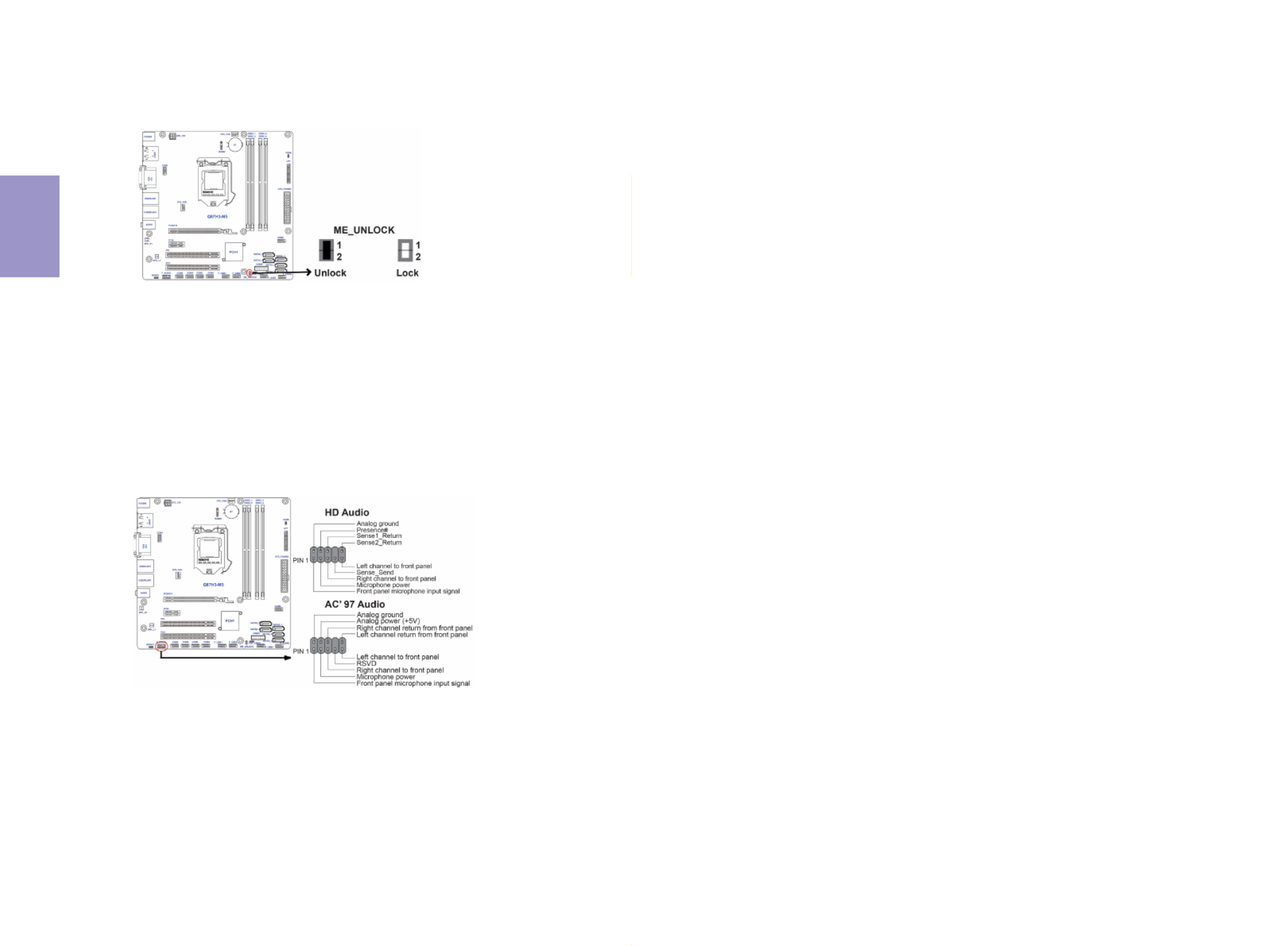
The front panel audio header allows the user to install auxiliary front-oriented mi-
crophone and line-out ports for easier access. This header supports HD audio by
default. If you want connect an AC’97 front panel audio to HD onboard headers,
please set as below picture.
8. F_AUDIO: Front Panel Audio Header
7. ME_UNLOCK: ME Unlock Header


Chapter 2
21
Q87H3-M5 USER MANUAL
If you use AC’97 Front Panel, please tick off the option of “Disabled Front Panel
Detect ”. If you use HD Audio Front Panel, please don’ “t tick off Disabled Front Panel
Detect ” .
* For reference only
AC’97 Audio Configuration: To enable the front panel audio connector to sup-
port AC97 Audio mode.
If you use AC’ 97 Front Panel, please don’ t tick off “Using Front Jack Detect ”. If you
use HD Audio Front Panel, please tick off the option of “Using Front Jack Detect ”.
* For reference only


Chapter 2
22
Q87H3-M5 USER MANUAL
2-4-6. Installing a SATA Hard Drive
About SATA Connectors
Your motherboard features five SATA connectors supporting a total of five drives.
SATA refers to Serial ATA (Advanced Technology Attachment) is the standard interface
for the IDE hard drives which are currently used in most PCs. These connectors are
well designed and will only fit in one orientation. Locate the SATA connectors on the
motherboard and follow the illustration below to install the SATA hard drives.
To install the Serial ATA (SATA) hard drives, use the SATA cable that supports the Serial
ATA protocol. This SATA cable comes with a SATA power cable. You can connect either
end of the SATA cable to the SATA hard drive or the connector on the motherboard.
Refer to the illustration below for proper installation:
1 Attach either cable end to the connector on the motherboard.
2 Attach the other cable end to the SATA hard drive.
3 Attach the SATA power cable to the SATA hard drive and connect the other
end to the power supply.
* For reference only
Installing Serial ATA Hard Drives
This section describes how to install a SATA Hard Drive.


Chapter 2
23
Q87H3-M5 USER MANUAL
After you have installed the motherboard into a case, you can begin connecting the
motherboard components. Refer to the following:
2-4-7. Connecting Case Components
No. Components No. Components
1 Buzzer 5 SPK_R1 & L1
2 CPU_FAN 6 SYS_FAN
3 ATX_POWER 7 ATX12V
4 F_PANEL ~~ ~~
1. Buzzer: Buzzer header
Connect the case buzzer cable to Buzzer.


Chapter 2
24
Q87H3-M5 USER MANUAL
3. ATX_POWER (ATX 24-pin Power Connector) & 7. ATX12V (ATX 12V Power
Connector)
Connect the standard power supply connector to ATX_POWER.
Connect the auxiliary case power supply connector to ATX12V.
2. CPU_FAN (CPU cooling FAN Power Connector) & 6. SYS_FAN (System Cool-
ing FAN Power Connector)
Users please note that the fan connector supports the CPU cooling fan of 1.1A
~ 2.2A (26.4W max) at +12V.
Connect the CPU cooling fan cable to CPU_FAN.
Connect the system cooling fan cable to SYS_FAN.


Chapter 2
25
Q87H3-M5 USER MANUAL
The ATX 24-pin connector allows you to connect to ATX v2.x power supply.
With ATX v2.x power supply, users please
note that when installing 24-pin power
cable, the latches of power cable and the
ATX match perfectly.
Connecting 24-pin power cable
24-pin power cable
The ATX12V4P power connector is used to provide power to the CPU.
When installing 4-pin power cable, the
latches of power cable and the ATX12V4P
match perfectly.
Connecting 4-pin power cable
4-pin power cable
5. SPK_R1 & L1 header
Connect the case speaker cable to SPK_R & L.


Chapter 2
26
Q87H3-M5 USER MANUAL
This concludes Chapter 2. The next chapter covers the BIOS.
Hard Drive Activity LED
Connecting pins 1 and 3 to a front panel mounted LED provides visual indication that
data is being read from or written to the hard drive. For the LED to function properly,
an IDE drive should be connected to the onboard IDE interface. The LED will also
show activity for devices connected to the SCSI (hard drive activity LED) connector.
Power/Sleep/Message waiting LED
Connecting pins 2 and 4 to a single or dual-color, front panel mounted LED provides
power on/off, sleep, and message waiting indication.
Reset Switch
Supporting the reset function requires connecting pin 5 and 7 to a momentary-con-
tact switch that is normally open. When the switch is closed, the board resets and
runs POST.
Power Switch
Supporting the power on/off function requires connecting pins 6 and 8 to a momen-
tary-contact switch that is normally open. The switch should maintain contact for at
least 50 ms to signal the power supply to switch on or off. The time requirement is
due to internal de-bounce circuitry. After receiving a power on/off signal, at least
two seconds elapses before the power supply recognizes another on/off signal.
4. Front Panel Header
The front panel header (F_PANEL) provides a standard set of switch and LED headers
commonly found on ATX or Micro ATX cases. Refer to the table below for information:


Chapter 3
Q87H3-M5 USER MANUAL
27
About the Setup Utility
The computer uses the latest “American Megatrends Inc. ” BIOS with support for
Windows Plug and Play. The CMOS chip on the motherboard contains the ROM setup
instructions for configuring the motherboard BIOS.
The BIOS (Basic Input and Output System) Setup Utility displays the system’s con-
figuration status and provides you with options to set system parameters. The pa-
rameters are stored in battery-backed-up CMOS RAM that saves this information
when the power is turned off. When the system is turned back on, the system is
configured with the values you stored in CMOS.
The BIOS Setup Utility enables you to configure:
The settings made in the Setup Utility affect how the computer performs. Before
using the Setup Utility, ensure that you understand the Setup Utility options.
This chapter provides explanations for Setup Utility options.
The Standard Configuration
A standard configuration has already been set in the Setup Utility. However, we rec-
ommend that you read this chapter in case you need to make any changes in the
future.
This Setup Utility should be used:
• when changing the system configuration
• when a configuration error is detected and you are prompted to make
changes to the Setup Utility
• when trying to resolve IRQ conflicts
• when making changes to the Power Management configuration
• when changing the password or making other changes to the Security
Setup
Entering the Setup Utility
When you power on the system, BIOS enters the Power-On Self Test (POST) routines.
POST is a series of built-in diagnostics performed by the BIOS. After the POST routines
are completed, the following message appears:
Press DEL to enter SETUP
Chapter 3
Using BIOS
• Hard drives, diskette drives and peripherals
• Video display type and display options
• Password protection from unauthorized use
• Power Management features

Chapter 3
Q87H3-M5 USER MANUAL
28
Press the delete key to access BIOS Setup Utility.
Using BIOS
When you start the Setup Utility, the main menu appears. The main menu of the
Setup Utility displays a list of the options that are available. A highlight indicates
which option is currently selected. Use the cursor arrow keys to move the highlight
to other options. When an option is highlighted, execute the option by pressing
<Enter>.
Some options lead to pop-up dialog boxes that prompt you to verify that you wish to
execute that option. Other options lead to dialog boxes that prompt you for informa-
tion.
Some options (marked with a triangle ) lead to submenus that enable you to change
the values for the option. Use the cursor arrow keys to scroll through the items in the
submenu.
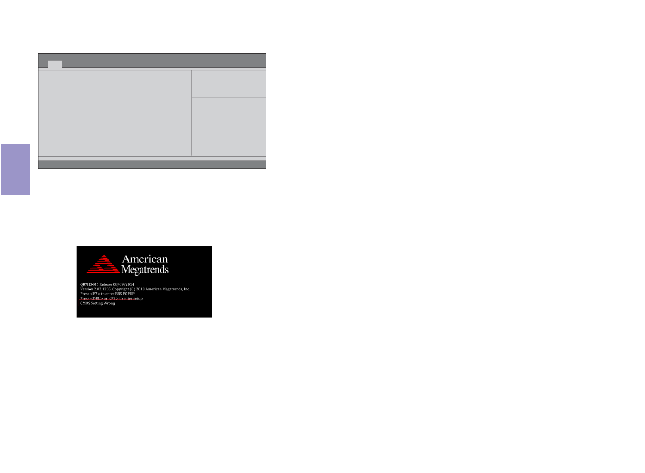
Resetting the Default CMOS Values
When powering on for the first time, the POST screen may show a “CMOS Settings
Wrong” message. This standard message will appear following a clear CMOS data
at factory by the manufacturer. You simply need to Load Default Settings and Save
it to reset the default CMOS values.
Note: Changes to system hardware such as different CPU, memories, etc. may
also trigger this message.
BIOS Information
System Language [English]
System Date [Fri 08/15/2014]
System Time [00:10:25]
Choose the system default
language
Aptio Setup Utility - Copyright (C) 2013 American Megatrends, Inc.
Version 2.16.1242. Copyright (C) 2013 American Megatrends, Inc.
F1:General Help
+/- : Change Opt.
Enter : Select
:Select Screen
:Select Item
F2:Previous Values
F3:Optimized Defaults
F4:Save & Exit
ESC:Exit
Main Advanced Chipset M.I.B.X Boot Security Exit


Chapter 3
Q87H3-M5 USER MANUAL
29
The default BIOS setting for this motherboard apply for most conditions
with optimum performance. We do not suggest users change the default
values in the BIOS setup and take no responsibility to any damage caused
by changing the BIOS settings.
BIOS Navigation Keys
The BIOS navigation keys are listed below:
In this manual, default values are enclosed in parenthesis. Submenu items are
denoted by a triangle .
For the purpose of better product maintenance, the manufacture reserves
the right to change the BIOS items presented in this manual. The BIOS setup
screens shown in this chapter are for reference only and may differ from
the actual BIOS. Please visit the manufacture’s website for updated
manual.
KEY FUNCTION
Scrolls through the items on a menu
+/-
F2 Previous Value
F3 Optimized Defaults
F1 General Help
ESC
Enter Select
F4 Save & Exit
Exits the current menu
Change Opt.


Chapter 3
Q87H3-M5 USER MANUAL
30
Main Menu
System Date & Time
The Date and Time items show the current date and time on the computer. If you are
running a Windows OS, these items are automatically updated whenever you make
changes to the Windows Date and Time Properties utility.
System Language (English)
This item is used to set system language.
When you enter the BIOS Setup program, the main menu appears, giving you an
overview of the basic system information. Select an item and press <Enter> to
display the submenu.
BIOS Information
System Language [English]
System Date [Fri 08/15/2014]
System Time [00:10:25]
Choose the system default
language
Aptio Setup Utility - Copyright (C) 2013 American Megatrends, Inc.
Version 2.16.1242. Copyright (C) 2013 American Megatrends, Inc.
F1:General Help
+/- : Change Opt.
Enter : Select
:Select Screen
:Select Item
F2:Previous Values
F3:Optimized Defaults
F4:Save & Exit
ESC:Exit
Main Advanced Chipset M.I.B.X Boot Security Exit


Chapter 3
Q87H3-M5 USER MANUAL
31
The Advanced menu items allow you to change the settings for the CPU and other
system.
Advanced Menu
Aptio Setup Utility - Copyright (C) 2013 American Megatrends, Inc.
Version 2.16.1242. Copyright (C) 2013 American Megatrends, Inc.
F1:General Help
+/- : Change Opt.
Enter : Select
:Select Screen
:Select Item
F2:Previous Values
F3:Optimized Defaults
F4:Save & Exit
ESC:Exit
LAN Configuration
PC Health Status
Power Management Setup
PCI Express Configuration
ACPI Settings
CPU Configuration
SATA Configuration
USB Configuration
Super IO Configuration
Trusted Computing
Intel (R) Rapid Start Technology
Intel (R) Smart Connect Technology
Intel ME BIOS Extension Configuration
LAN Configuration Parameters
Main Advanced Chipset M.I.B.X Boot Security Exit


Chapter 3
Q87H3-M5 USER MANUAL
32
LAN Configuration
The item in the menu shows the LAN-related information that the BIOS
automatically detects.
Onboard LAN 1 Controller (Enabled)
Use this item to enable or disable Onboard LAN 1 controller.
Enabled/Disabled Onboard Lan 1
Controller
LAN Configuration
Onboard LAN 1 Controller [Enabled]
Onboard LAN 2 Controller [Enabled]
Aptio Setup Utility - Copyright (C) 2013 American Megatrends, Inc.
Version 2.16.1242. Copyright (C) 2013 American Megatrends, Inc.
Advanced
F1:General Help
+/- : Change Opt.
Enter : Select
:Select Screen
:Select Item
F2:Previous Values
F3:Optimized Defaults
F4:Save & Exit
ESC:Exit
Press <Esc> to return to the Advanced Menu page.
Onboard LAN 2 Controller (Enabled)
Use this item to enable or disable Onboard LAN 2 controller.


Chapter 3
Q87H3-M5 USER MANUAL
33
PC Health Status
On motherboards support hardware monitoring, this item lets you monitor the
parameters for critical voltages, temperatures and fan speeds.
CPU Temperature (DTS) 42
System Temperature 30
O C
CPU Fan Speed 3308 RPM
System Fan Speed 0 RPM
Processor Input Voltage 1.733V
DIMM Voltage 1.504V
+12V 12.096V
+5V 5.064V
+3.3V 3.410V
TCC Activation Temperature (DTS) 75
Version 2.16.1242. Copyright (C) 2013 American Megatrends, Inc.
Aptio Setup Utility - Copyright (C) 2013 American Megatrends, Inc.
F1:General Help
+/- : Change Opt.
Enter : Select
:Select Screen
:Select Item
F2:Previous Values
F3:Optimized Defaults
F4:Save & Exit
ESC:Exit
PC Health Status
Advanced
Smart Fan Function
Smart Fan start PWM value 180
Smart Fan start PWM TEMP (DTS) 45
DeltaT +3
Smart Fan Slope PWM value 10 PWM value / unit
CPU Fan Full Speed Offset (DTS) 52
Version 2.16.1242. Copyright (C) 2013 American Megatrends, Inc.
Aptio Setup Utility - Copyright (C) 2013 American Megatrends, Inc.
F1:General Help
+/- : Change Opt.
Enter : Select
:Select Screen
:Select Item
F2:Previous Values
F3:Optimized Defaults
ESC:Exit
CPU Smart Fan Control [Enabled]
Smart Fan Mode [Normal]
Advanced
System Smart Fan Control [Enabled]
Smart Fan Mode [Normal]
Smart Fan start PWM value 180
Smart Fan start PWM TEMP (DTS) 45
DeltaT +3
Smart Fan Slope PWM value 10 PWM value / unit
System Fan Full Speed Offset (DTS) 52
Enable System Smart Fan
F4:Save & Exit
Smart Fan Function
Scroll to this item and press <Enter> to view the following screen:
CPU/System Fan Smart Fan Control (Enabled)
These items enable you to define the CPU/system fan by smartly adjusting the CPU/
system fan. When it is set at certain temperature, the CPU/system fan PWM value
will change accordingly.


Chapter 3
Q87H3-M5 USER MANUAL
34
• CPU Temperature
• System Temperature
• CPU Fan Speed
• System Fan Speed
• Processor Input Voltage
• DIMM Voltage
• +12V
• +5V
• +3.3V
System Component Characteristics
These items display the monitoring of the overall inboard hardware health events,
such as System temperature, CPU & DIMM voltage, CPU & System fan speed... etc.
Press <Esc> to return to the Advanced Menu page.
Smart Fan Mode (Normal)
This item allows you to select the fan mode (Normal, Quiet, Silent, or Manual) for a
better operation environment. If you choose Normal mode, the fan speed will be
auto adjusted depending on the CPU temperature. If you choose Quite mode, the
fan speed will be auto minimized for quiet environment. If you choose Silent mode,
the fan speed will be auto restricted to make system more quietly. If you choose
Manual mode, the fan speed will be adjust depending on users’ parameters.
Smart Fan start PWM value (180)
Smart Fan start PWM TEMP (DTS) (45)
This item is used to set the start PWM value of the smart fan.
This item is used to set the start temperature of the smart fan.
DeltaT (+3)
This item specifies the range that controls CPU temperature and keeps it from going
so high or so low when smart fan works.
Smart Fan Slope PWM value (10 PWM value/unit)
This item is used to set the Slope Select PWM of the smart fan.
This item is used to set the CPU fan/System fan full speed offset value.
CPU Fan/System Fan Full Speed Offset (DTS) (52)
Press <Esc> to return to the PC Health Status page.


Chapter 3
Q87H3-M5 USER MANUAL
35
Power Management Setup
This page sets up some parameters for system power management operation.
Resume By PME (Disabled)
This item specify whether the system will be awakened from power saving modes
when activity or input signal of the specified hardware peripheral or components is
detected.
EUP Function (Enabled)
This item allows user to enable or disable EUP support.
Power Management Setup
Resume By RING [Disabled]
Resume By PME [Disabled]
Wake on LAN [Disabled]
Resume By USB [Disabled]
Resume By PS2 KB [Disabled]
Resume By PS2 MS [Disabled]
Resume By RTC Alarm [Disabled]
EUP Function [Enabled]
Power LED Type [Dual Color LED]
Aptio Setup Utility - Copyright (C) 2013 American Megatrends, Inc.
Advanced
Version 2. 16.1242. Copyright (C) 2013 American Megatrends, Inc.
About Resume by Ring
F1:General Help
+/- : Change Opt.
Enter : Select
:Select Screen
:Select Item
F2:Previous Values
F3:Optimized Defaults
F4:Save & Exit
ESC:Exit
Press <Esc> to return to the Advanced Menu page.
Resume By USB (Disabled)
This item allows you to enable/disable the USB device wakeup function from S3
mode.
Resume By RTC Alarm (Disabled)
The system can be turned off with a software command. If you enable this item,
the system can automatically resume at a fixed time based on the system’s RTC
(realtime clock). Use the items below this one to set the date and time of the wake-
up alarm. You must use an ATX power supply in order to use this feature.
Resume By RING (Disabled)
The system can be tured off with a software command. If you enable this item, the
system can automatically resume if there is an incoming call on the modem. You
must use an ATX power supply in order to use this feature.
Wake on LAN (Disabled)
Use this item to enable or disable integrated LAN to wake the system. (The Wake on
LAN cannot be disabled if ME is on at Sx state.) If disabled, resume by USB (S3) will not
be available.
Resume By PS2 KB (Disabled)
This item enables or disables you to allow keyboard activity to awaken the system
from power saving mode.
Resume By PS2 MS (Disabled)
This item enables or disables you to allow mouse activity to awaken the system
from power saving mode.
Power LED Type (Dual Color LED)
This item shows the type of the power LED.


Chapter 3
Q87H3-M5 USER MANUAL
36
NB PCI Express Configuration
PCI Express 16X
PCI Express 16X Speed [Auto]
Aptio Setup Utility - Copyright (C) 2013 American Megatrends, Inc.
Version 2.16.1242. Copyright (C) 2013 American Megatrends, Inc.
Configure PCIE slot Speed
Advanced
F1:General Help
+/- : Change Opt.
Enter : Select
:Select Screen
:Select Item
F2:Previous Values
F3:Optimized Defaults
F4:Save & Exit
ESC:Exit
PCI Express Configuration
This page sets up PCI Express configuration.
PCI Express 16X Speed (Auto)
This item allows you to set the PCIe X16 speed.
Press <Esc> to return to the Advanced Menu page.
PCI Express Configuration
PCIE1
PCIe Speed [Auto]
PCIE1 PCIe Speed (Auto)
This item enables you to set the PCI Express speed.


Chapter 3
Q87H3-M5 USER MANUAL
37
ACPI Configuration
The item in the menu shows the highest ACPI sleep state when the system enters
suspend.
ACPI Sleep State [S3(Suspend to RAM)]
This item allows user to enter the ACPI S3 (Suspend to RAM) Sleep State (default).
Press <Esc> to return to the Advanced Menu page.
ACPI Settings
ACPI Sleep State [S3 (Suspend to RAM)]
Aptio Setup Utility - Copyright (C) 2013 American Megatrends, Inc.
Version 2.16.1242. Copyright (C) 2013 American Megatrends, Inc.
Select the highest ACPI sleep
state the system will enter
when the SUSPEND button is
pressed.
Advanced
F1:General Help
+/- : Change Opt.
Enter : Select
:Select Screen
:Select Item
F2:Previous Values
F3:Optimized Defaults
F4:Save & Exit
ESC:Exit


Chapter 3
Q87H3-M5 USER MANUAL
38
Intel (R) Core (TM) i7-4765T CPU @2.00GHz
This is display field and displays the information of the CPU installed in your com-
puter.
Processor Stepping (306c3)
This item shows the processor stepping revision.
Processor Speed (2000MHz)
This item shows the current processor speed.
EM64T (Supported)
This item shows the computer supports EM64T.
Intel HT Technology (Supported)
This item shows the computer supports Intel HT Technology.
Microcode Revision (19)
This item shows the Microcode revision.
Processor Cores (4)
This item shows the core number of the processor.
CPU Configuration
The item in the menu shows the CPU Configuration.
CPU Configuration
Intel (R) Core (TM) i7-4765T CPU @ 2.00GHz
EM64T Supported
Processor Speed 2000 MHz
Processor Stepping 306c3
Microcode Revision 19
Processor Cores 4
Intel HT Technology Supported
Intel VT-X Technology Supported
Hyper-threading [Enabled]
Active Processor Cores [All]
Limit CPUID Maximum [Disabled]
Execute Disable Bit [Enabled]
Intel Virtualization Technology [Enabled]
LakeTiny Feature [Enabled]
CPU C3 Report [Enabled]
CPU C6 Report [Enabled]
CPU C7 Report [C7s]
Package C State limit [AUTO]
Enhanced Halt (C1E) [Enabled]
Aptio Setup Utility - Copyright (C) 2013 American Megatrends, Inc.
Version 2.16.1242. Copyright (C) 2013 American Megatrends, Inc.
Enabled for windows XP and Linx
(OS optimized for Hyper-Threading
Technology) and Disabled for other
OS (OS not optimized for Hyper-
Threading Technology). When
disabled only one thread per enabled
core is enabled.
Advanced
F1:General Help
+/- : Change Opt.
Enter : Select
:Select Screen
:Select Item
F2:Previous Values
F3:Optimized Defaults
F4:Save & Exit
ESC:Exit
Intel VT-X Technology (Supported)
This item shows the computer supports Intel VT-X Technology.
Hyper-threading (Enabled)
This item only available when the chipset supports Hyper-threading and you are
using a Hyper-threading CPU.


Chapter 3
Q87H3-M5 USER MANUAL
39
Press <Esc> to return to the Advanced Menu page.
Active Processor Cores (All)
Use this item to control the number of active processor cores.
Limit CPUID Maximum (Disabled)
Use this item to enable or disable the maximum CPUID value limit, you can enable
this item to prevent the system from “rebooting” when trying to install Windows
NT4.0.
Execute Disabled Bit (Enabled)
This item allows the processor to classify areas in memory by where application
code can excute and where in cannot. When a malicious worm attempts to insert
code in the buffer, the processor disables code excution, preventing damage or worm
propagation. Replacing older computers with Excute Disable Bit enabled systems
can halt worm attacks, reducing the need for virus related repair.
Intel Vitualization Technology (Enabled)
When disabled, a VMM cannot utilize the additional hardware capabilities provided
by Vandor Pool Technology.
LakeTiny Feature (Enabled)
Use this item to enable or disable the LakeTiny for C state configuration.
CPU C3 Report (Enabled)
Use this item to enable or disable CPU C3 (ACPI C2) report to OS.
CPU C6 Report (Enabled)
Use this item to enable or disable CPU C6 (ACPI C3) report to OS.
CPU C7 Report (C7s)
Use this item to enable or disable CPU C7 report to OS.
Package C State limit (AUTO)
Use this item to set package C state limit.
Enhanced Halt (C1E)
Use this item to enable or disable the Enhanced C1 state.


Chapter 3
Q87H3-M5 USER MANUAL
40
SATA Configuration
Use this item to show the mode of serial SATA configuration options.
SATA Mode (AHCI Mode)
Use this item to select SATA mode.
SATA Port1~5 (Not Present)
This motherboard supports five SATA channels and each channel allows one SATA
device to be installed. Use these items to configure each device on the SATA channel.
Press <Esc> to return to the Advanced Menu page.
SATA Configuration
SATA Mode [AHCI Mode]
SATA Port1
Not Present
Spin Up Device [Disabled]
External SATA [Disabled]
Aptio Setup Utility - Copyright (C) 2013 American Megatrends, Inc.
Version 2.16.1242. Copyright (C) 2013 American Megatrends, Inc.
Determines how SATA controllers
operate.
Advanced
F1:General Help
+/- : Change Opt.
Enter : Select
:Select Screen
:Select Item
F2:Previous Values
F3:Optimized Defaults
F4:Save & Exit
ESC:Exit
SATA Port2
Not Present
Spin Up Device [Disabled]
External SATA [Disabled]
SATA Port3
Not Present
Spin Up Device [Disabled]
External SATA [Disabled]
SATA Port4
Not Present
Spin Up Device [Disabled]
External SATA [Disabled]
SATA Port5
Not Present
Spin Up Device [Disabled]
External SATA [Disabled]
Spin up Device (Disabled)
On an edge detect from 0 to 1, the PCH starts a COMRESET inization sequence to the
device.
External SATA (Disabled)
Use this item to enable or disable External SATA Support.


Chapter 3
Q87H3-M5 USER MANUAL
41
USB Configuration
All USB Devices [Enabled]
Legacy USB Support [Enabled]
Aptio Setup Utility - Copyright (C) 2013 American Megatrends, Inc.
Version 2.16.1242. Copyright (C) 2013 American Megatrends, Inc.
USB Support Parameters
Advanced
F1:General Help
+/- : Change Opt.
Enter : Select
:Select Screen
:Select Item
F2:Previous Values
F3:Optimized Defaults
F4:Save & Exit
ESC:Exit
USB Configuration
Use this item to show the information of USB configuration.
All USB Devices (Enabled)
Use this item to enable or disable all USB devices.
Press <Esc> to return to the Advanced Menu page.
Legacy USB Support (Enabled)
Use this item to enable or disable support for legacy USB devices.


Chapter 3
Q87H3-M5 USER MANUAL
42
Super IO Configuration
Super IO Chip IT8732, IT8768
Aptio Setup Utility - Copyright (C) 2013 American Megatrends, Inc.
Version 2.16.1242. Copyright (C) 2013 American Megatrends, Inc.
Set Parameters of Serial Port
1 (COMA)
Advanced
F1:General Help
+/- : Change Opt.
Enter : Select
:Select Screen
:Select Item
F2:Previous Values
F3:Optimized Defaults
F4:Save & Exit
ESC:Exit
Serial Port 0 Configuration
Serial Port 1 Configuration
Serial Port 2 Configuration
Serial Port 3 Configuration
Serial Port 4 Configuration
Serial Port 5 Configuration
Parallel Port Configuration
Super IO Configuration
Use this item to show the information of Super IO configuration.
Super IO Chip (IT8732, IT8768)
This item shows the information of the super IO chip.
Serial Port 0 Configuration
Scroll to this item and press <Enter> to view the following screen:
Aptio Setup Utility - Copyright (C) 2013 American Megatrends, Inc.
Version 2.16.1242. Copyright (C) 2013 American Megatrends, Inc.
Serial Port
Advanced
F1:General Help
+/- : Change Opt.
Enter : Select
:Select Screen
:Select Item
F2:Previous Values
F3:Optimized Defaults
F4:Save & Exit
ESC:Exit
Change Settings [Auto]
Serial Port 0 Configuration
Serial Port [Enabled]
Device Settings IO=3F8h; IRQ=4;
Serial Port (Enabled)
This item allows you to enable or disable serial port.
Device Settings (IO=3F8h; IRQ=4)
This item shows the information of the device settings.
Change Settings (Auto)
Use this item to change device settings.
Press <Esc> to return to the Super IO Configuration page.


Chapter 3
Q87H3-M5 USER MANUAL
43
Serial Port 1 Configuration
Scroll to this item and press <Enter> to view the following screen:
Aptio Setup Utility - Copyright (C) 2013 American Megatrends, Inc.
Version 2.16.1242. Copyright (C) 2013 American Megatrends, Inc.
Serial Port
Advanced
F1:General Help
+/- : Change Opt.
Enter : Select
:Select Screen
:Select Item
F2:Previous Values
F3:Optimized Defaults
F4:Save & Exit
ESC:Exit
Change Settings [Auto]
Serial Port 1 Configuration
Serial Port [Enabled]
Device Settings IO=2F8h; IRQ=3;
Serial Port (Enabled)
This item allows you to enable or disable serial port.
Device Settings (IO=2F8h; IRQ=3)
This item shows the information of the device settings.
Change Settings (Auto)
Use this item to change device settings.
Press <Esc> to return to the Super IO Configuration page.
Serial Port 2 Configuration
Scroll to this item and press <Enter> to view the following screen:
Aptio Setup Utility - Copyright (C) 2013 American Megatrends, Inc.
Version 2.16.1242. Copyright (C) 2013 American Megatrends, Inc.
Serial Port
Advanced
F1:General Help
+/- : Change Opt.
Enter : Select
:Select Screen
:Select Item
F2:Previous Values
F3:Optimized Defaults
F4:Save & Exit
ESC:Exit
Change Settings [Auto]
Serial Port 2 Configuration
Serial Port [Enabled]
Device Settings IO=260h; IRQ=6;
Serial Port (Enabled)
This item allows you to enable or disable serial port.


Chapter 3
Q87H3-M5 USER MANUAL
44
Device Settings (IO=260h; IRQ=6)
This item shows the information of the device settings.
Change Settings (Auto)
Use this item to change device settings.
Press <Esc> to return to the Super IO Configuration page.
Serial Port 3 Configuration
Scroll to this item and press <Enter> to view the following screen:
Aptio Setup Utility - Copyright (C) 2013 American Megatrends, Inc.
Version 2.16.1242. Copyright (C) 2013 American Megatrends, Inc.
Serial Port
Advanced
F1:General Help
+/- : Change Opt.
Enter : Select
:Select Screen
:Select Item
F2:Previous Values
F3:Optimized Defaults
F4:Save & Exit
ESC:Exit
Change Settings [Auto]
Serial Port 3 Configuration
Serial Port [Enabled]
Device Settings IO=268h; IRQ=6;
Serial Port (Enabled)
This item allows you to enable or disable serial port.
Device Settings (IO=268h; IRQ=6)
This item shows the information of the device settings.
Change Settings (Auto)
Use this item to change device settings.
Press <Esc> to return to the Super IO Configuration page.


Chapter 3
Q87H3-M5 USER MANUAL
45
Serial Port 4 Configuration
Scroll to this item and press <Enter> to view the following screen:
Aptio Setup Utility - Copyright (C) 2013 American Megatrends, Inc.
Version 2.16.1242. Copyright (C) 2013 American Megatrends, Inc.
Serial Port
Advanced
F1:General Help
+/- : Change Opt.
Enter : Select
:Select Screen
:Select Item
F2:Previous Values
F3:Optimized Defaults
F4:Save & Exit
ESC:Exit
Change Settings [Auto]
Serial Port 4 Configuration
Serial Port [Enabled]
Device Settings IO=270h; IRQ=6;
Serial Port (Enabled)
This item allows you to enable or disable serial port.
Device Settings (IO=3F8h; IRQ=4)
This item shows the information of the device settings.
Change Settings (Auto)
Use this item to change device settings.
Press <Esc> to return to the Super IO Configuration page.


Chapter 3
Q87H3-M5 USER MANUAL
46
Serial Port 5 Configuration
Scroll to this item and press <Enter> to view the following screen:
Aptio Setup Utility - Copyright (C) 2013 American Megatrends, Inc.
Version 2.16.1242. Copyright (C) 2013 American Megatrends, Inc.
Serial Port
Advanced
F1:General Help
+/- : Change Opt.
Enter : Select
:Select Screen
:Select Item
F2:Previous Values
F3:Optimized Defaults
F4:Save & Exit
ESC:Exit
Change Settings [Auto]
Serial Port 5 Configuration
Serial Port [Enabled]
Device Settings IO=278h; IRQ=6;
Serial Port (Enabled)
This item allows you to enable or disable serial port.
Device Settings (IO=3F8h; IRQ=4)
This item shows the information of the device settings.
Change Settings (Auto)
Use this item to change device settings.
Press <Esc> to return to the Super IO Configuration page.

Produkt Specifikationer
| Mærke: | ECS |
| Kategori: | Bundkort |
| Model: | Q87H3-M5 |
Har du brug for hjælp?
Hvis du har brug for hjælp til ECS Q87H3-M5 stil et spørgsmål nedenfor, og andre brugere vil svare dig
Bundkort ECS Manualer

12 Januar 2025
12 Januar 2025
12 Januar 2025
12 Januar 2025
11 Januar 2025
11 Januar 2025
16 November 2024
18 August 2024
17 August 2024
17 August 2024
Bundkort Manualer
- Bundkort Asus
- Bundkort Gigabyte
- Bundkort Asrock
- Bundkort MSI
- Bundkort NZXT
- Bundkort Sapphire
- Bundkort Intel
- Bundkort Sharkoon
- Bundkort Supermicro
- Bundkort Biostar
- Bundkort Evga
- Bundkort Foxconn
- Bundkort Advantech
- Bundkort Elitegroup
- Bundkort EPoX
- Bundkort AOpen
- Bundkort Raspberry Pi
Nyeste Bundkort Manualer
29 Marts 2025

27 Marts 2025
6 Marts 2025
15 Februar 2025

15 Februar 2025
15 Februar 2025
15 Februar 2025
15 Februar 2025
15 Februar 2025
15 Februar 2025