FLIR M500 Manual
FLIR
Overvågningskamera
M500
Læs nedenfor 📖 manual på dansk for FLIR M500 (43 sider) i kategorien Overvågningskamera. Denne guide var nyttig for 16 personer og blev bedømt med 4.5 stjerner i gennemsnit af 2 brugere
Side 1/43

Operator’s
Manual
M500
This document does not contain export-controlled information

432-0012-01-10 Version 110 2
© 20 FLIR Systems, Inc. All rights re20 served ide. No s of th manual, in whole or in part may be worldw part is ,
copied, hotocopied, nslated, or transmitted to any p tra electronic medium or machine readable fo without the rm
prior written permission of FLIR Systems, Inc.Names an marks appearingd on the products herein are either
registered trademark or trademarks ofs FLIR Systems, Inc. and/or its subs idiaries. All other trademarks, trade
names, or comp names referenced herein are used fo any r identification only and are the property of their
respective owners.
This d by product is protecte patents, n ate desig p nts, patents pending, or design patents pending.
Photographs and een imag appearing in this manual may have bes modified for illustrative purposes using
commercial image editing software and may not always reflect an actual product configuration.
The cont this d are subject change ithents of ocument to w out notice.
For a information vdditional isit https://www.flir.com/ or write to FLIR Systems, Inc.
FL System Inc.IR s,
6769 Hollister Ave.
Goleta, CA 93117
Phone: 888.74 (888.747.3547)7.FLIR
International: +1.805.964.9797
maritimecamerasupport@flir.com
Proper of Disposal Electrical and Electronic E (EEE)quipment
The European Union (EU) has enacted Waste Electrical and Electronic Equipment Directive
2002/96/EC (WEEE), which aims to prevent EEE waste from arising; to encourage reuse,
recycling, and recovery of EEE waste; and to promote environmental responsibility.
In accordance with these regulations, all EEE products labeled with the “crossed out wheeled
bin” either on the product itself or in the product literature must not be disposed of in regular
rubbish bins, mixed with regular household or other commercial waste, or by other regular
municipal waste collection means. Instead, and in order to prevent possible harm to the
environment or human health, all EEE products (including any cables that came with the product) should be
responsibly discarded or recycled.
To identify a responsible disposal method where you live, please contact your local waste collection or recycling
service, your original place of purchase or product supplier, or the responsible government authority in your area.
Business users should contact their supplier or refer to their purchase contract.
Document History
Version Date Comment
100 December 2017 initial release
110 July 2018 added cryocooler controls, additional visible camera features,
and GUI language choices
August 2020
August 2020

432-0012-01-10 Version 110 3
Contents
M500 Overview
General Information..............................................................................7
Additional References ....................................................................7
Documentation Conventions ..........................................................8
Warnings and Cautions ........................................................................8
System Description ..............................................................................9
Standard Features..........................................................................9
M500 Components: ......................................................................10
Multiple Cameras, Joysticks, and Other Devices: ........................10
Thermal Video Display .......................................................................11
Video Screen Icons ......................................................................11
Position indicator icons ..........................................................12
Scene Preset icons ...............................................................12
Active Camera Icons .............................................................12
On-Screen-Display (OSD) Menu ...........................................12
M500 System Startup
System Startup and Shutdown ...........................................................13
Park Mode ..........................................................................................13
The Bootup Process...........................................................................13
Powering the Camera...................................................................13
Powering the JCU II......................................................................14
JCU II Power Menu ............................................................................14
Standby States..............................................................................14
M500 Joystick Control Unit
Introduction.........................................................................................16
JCU II Joystick....................................................................................16
Tilting the Camera ........................................................................16
Rotating the Camera ....................................................................16
Zooming the Camera....................................................................16
JCU II Buttons ....................................................................................17
Power Button .........................................................................17
Menu Button ..........................................................................17
August 2020

Contents
432-0012-01-10 Version 110 4
Home Button ..........................................................................17
Scene Button—IR imaging only .............................................18
Color Button—IR Imaging only ..............................................18
Focus Buttons ........................................................................18
Camera Button ......................................................................18
User Buttons ..........................................................................18
Display Camera and JCU II IP Address .................................19
Button Summary...........................................................................19
M500 System Configuration
Overview ............................................................................................20
Main Menu..........................................................................................20
Immediate Action Menu Buttons...................................................21
Tracker: .................................................................................21
Park camera: .........................................................................21
InstAlert/Exit InstAlert mode: .................................................21
IceAlert/Exit IceAlert mode: ...................................................21
Surveillance: ..........................................................................22
Scan Width: ...........................................................................22
Scan Speed: ..........................................................................22
NMEA: ...................................................................................22
Spotlight: ................................................................................22
Image and Settings Configuration Menus ....................................23
Image... ..................................................................................23
Settings… ..............................................................................23
Help… ....................................................................................23
Image Menu .......................................................................................24
Polarity—IR camera only: ......................................................24
Stabilization: ..........................................................................24
Autofocus ...............................................................................24
Color: .....................................................................................24
VIS low light mode: ................................................................25
IR/Daylight zoom link: ............................................................25
Mirrored view: ........................................................................25
Settings Menu ....................................................................................25
Save current settings as start-up defaults: ............................25
Restore settings from defaults: ..............................................25
Advanced image... .................................................................25
User interface… .....................................................................25
Surveillance… .......................................................................26
NMEA… .................................................................................26
Calibration & diagnostics Menu ....................................................26
IR test pattern: .......................................................................26
Activate spotlight test: ............................................................26
Activate pan and tilt test: .......................................................26
Reset IR Lens: .......................................................................26
August 2020

Contents
432-0012-01-10 Version 110 5
Set Az & El zero reference: ...................................................26
Advanced Image Menu.................................................................27
IR eZoom, VIS eZoom: ..........................................................27
VIS low light mode: ................................................................27
VIS wide dynamic range: .......................................................27
VIS electronic stabilization: ....................................................27
VIS defog: ..............................................................................27
InstAlert highlight, IceAlert highlight ......................................28
IR cooler: ...............................................................................28
User Interface Menu.....................................................................28
Interface Language: ...............................................................28
Display icons: ........................................................................28
Help text: ...............................................................................29
Icon & text color: ....................................................................29
Tracking box: .........................................................................29
Pilot mode: .............................................................................29
User button 1, User button 2, User button 3: .........................29
NMEA Data.........................................................................................29
NMEA Settings .............................................................................30
Radar cursor (RSD): ..............................................................30
Next Waypoint (BWC): ..........................................................31
Radar target (TTM): ...............................................................31
Video Tracking Mode
Overview ...........................................................................................32
Joystick Operation .............................................................................34
Video Tracker Errors ..........................................................................34
Online Tracker Help............................................................................35
M500 Reference Information
Introduction.........................................................................................36
Acronyms ...........................................................................................36
List of Icons ........................................................................................37
System Specifications ........................................................................40
Troubleshooting Tips ..........................................................................41
Video not displayed on monitor .............................................41
Cleaning ................................................................................41
Video not switching between thermal and visible ..................41
Noisy image ...........................................................................41
Image too dark or too light .....................................................42
Performance varies with time of day .....................................42
Eastern or Western exposure ................................................42
August 2020

Contents
432-0012-01-10 Version 110 6
Multiple Cameras and/or JCU IIs on a single network ...........42
August 2020

432-0012-01-10 Version 110 7
1
M500 Overview
General Information
This manual describes the operation of the M500 ve additional cameras. If you need help or ha
questions, please call to speak with our support experts; refer to contact information listed on the
back cover of this manual.
This manual includes the following topics:
• System description
• Using the Joystick Control Unit
• System startup and shutdown
• Using Video Tracking mode
• Using the on-screen-display (OSD) menus for controlling the M500
• Helpful reference information such as acronyms, parts lists, a table of icons, and a comparison
of model features
Additional References
The M500 system comes with a complete documentation set, available on the FLIR website, that
includes this manual as well as other information. All documents are in PDF format and can be
viewed with Adobe Acrobat Reader:
•M500 Installation Guide (FLIR Doc. # 432-0012-01-12) contains information about how to
install the camera, video setup configurations, password management, and other configuration
setting.
•M500 Quick Start Guide (FLIR Doc. # 432-0012-01-11) is a double-sided card that shows the
functions executed by the Joystick Control Unit.
Refer to the FLIR Web page for up-to-date documentation:
https://www.flir.com/
August 2020

Warnings and Cautions
432-0012-01-10 Version 110 8
Documentation Conventions
For safety, and to achieve the highest levels of performance from the M500 system, always follow
the warnings and cautions in this manual when handling and operating the M500 system.
Warning: Warning notices are used to emphasize that hazardous voltages, currents,
temperatures, or other conditions that could cause personal injury or death exist with this
equipment, or may be associated with its use.
Caution: Caution notices are used where equipment might be damaged if care is not taken or an
operation might have an unexpected outcome.
Note: Notes call attention to information that is especially significant to understanding and
operating the equipment.
Warnings and Cautions
Warning: Do not use the M500 system as the primary navigation system. Use it in conjunction
with other navigation aids and a primary manual navigation system.
Warning: Ensure power is removed before accessing power wires during installation or removal of
system components. Damage to equipment or injury to personnel may result.
Warning: Use of insufficient wire gauge can result in fire.
Warning: The M500 system is not designed to operate in an enclosed environment in the
presence of flammable gases. Failure to follow this warning may result in explosion or fire.
Warning: The M500 camera body is a remotely and automatically controlled device. Ensure
camera motion has been disabled before cleaning surfaces that can cause pinch hazards.
Caution: Do not open the M500 unit for any reason. Disassembly of the M500
(including removal of the cover) can cause permanent damage and will void the warranty.
Caution: Be careful not to leave fingerprints on the M500 optics.
Caution: The M500 requires a power supply of 12 Vdc to 24 Vdc nominal, 5.5 A maximum @
24 Vdc, 11 A maximum @ 12 Vdc. Absolute voltage range: 12 Vdc to 32 Vdc. Operating the
system outside of the specified input voltage range or the specified operating temperature range
can cause permanent damage.
Operating temperature range –20 °C to +55 °C (–4 °F to +131 °F) per IEC 60945
Storage temperature range –50 °C to +80 °C (–58 °F to +176 °F)
August 2020

System Description
432-0012-01-10 Version 110 9
System Description
The multi-sensor M500 is a stabilized maritime thermal and high definition (HD) visible-light
camera system for use on most types of vessels. The mid-wave infrared (MWIR) thermal camera
with 14X optical zoom provides excellent nighttime visibility and situational awareness, without any
form of natural or artificial illumination. The HD visible-light camera with 30X optical zoom provides
daytime viewing.
Standard Features
• Cryogenically cooled thermal camera with On/Off cooler control,
14x continuous optical zoom
• HD visible-light camera,
30x continuous optical zoom
• High intensity LED spotlight
• Active gyro-stabilization
• Radar integration to follow specific radar targets (NMEA 0183 serial communications)
• Dual, independent H.264 network video streams
• HD-SDI (Serial data interface)
• Analog video
The thermal camera, HD visible-light camera, and spotlight are aligned to view or illuminate a
target for quick identification providing enhanced navigational abilities in a variety of conditions.
Figure 1-1: M500 Pan/Tilt Camera System
LED spotlight
Thermal camera
HD visible-light camera
Joystick Control Unit
(JCU II)
August 2020

System Description
432-0012-01-10 Version 110 10
M500 Components:
• Main camera body, also known as the pan/tilt camera unit
• Joystick Control Unit (JCU II), compatible with the MU, MV, M400, and M500 camera systems
• Ethernet switch with power over Ethernet (PoE) to power the JCU II and network to the camera
• Analog and/or digital video monitors (customer supplied)
• Personal computer (PC) to control and configure the system (customer supplied)
The M500 camera body and JCU II are network devices. In some installations, additional M500
cameras and/or additional JCU II may also be used.
The camera body’s pan/tilt mechanism allows the operator to rotate 360° in azimuth, tilt +/– 90° in
elevation. The camera body houses the two cameras, and the LED spotlight. The cyrocooler
requires approximately six minutes to cool the thermal sensor before IR video is usable.
Note: If the IR video is not required as an instant on feature, use the cooler On/Off control to
lower power usage and extend the cooler lifetime. See “IR cooler:” on page 28.
The JCU II is the primary control for the camera. The JCU II is used to wake the system or put it in
standby, select the active camera, operate the pan and tilt movement of the camera, zoom the
active camera, control the M500 modes and features, and configure the system settings by means
of OSD menus.
The JCU II has buttons, an LCD display, and the joystick. The joystick can be moved left and right
or forward and back, and rotated in either direction. “M500 Joystick Control Unit” on page 16
describes the functions of the JCU II in detail.
The M500 uses on-screen icons to indicate the camera position (azimuth and elevation) and
various system settings that have been enabled. These symbols are introduced in “Thermal Video
Display” on page 11 and are further explained throughout this manual in the discussion of related
functions.
Multiple Cameras, Joysticks, and Other Devices:
More than one JCU II can be used to control the camera, and more than one display can be used
to view the video. A personal computer (PC) on the same network as the camera, can use a web
browser to view video, control, and configure the system. The camera’s web server uses password
protected accounts to control access to camera functions. Using a PC is described in the M500
Installation Guide.
Also, a single JCU II can be used to select and control more than one camera. In this case, a
menu on the JCU II lists available cameras. In the LCD display of the JCU II, the name of the
currently selected camera is displayed. When more than one JCU II is installed in the network, a
camera will respon JCU II that has the camd to commands from any era selected.
Typically, a JCU II and a video monitor are mounted in close physical proximity, as a pair, so you
can immediately see the changes on the video screen when you use the JCU II to change the
camera position (pan or tilt).
Contact FLIR Systems, Inc. for more information regarding available accessories including PoE
equipment, video distribution amplifiers, cables, connectors, mounting hardware, etc. Contact
information is listed on the back of this manual.
August 2020

Thermal Video Display
432-0012-01-10 Version 110 11
Thermal Video Display
The infrared (IR) imaging thermal camera relies on the fact that all objects, even very cold objects
like ice, emit thermal energy in the portion of the infrared spectrum that the camera can see.
Therefore, unlike an illuminated infrared camera, the thermal imaging camera does not need an
additional active illumination source and images are based on directly radiated energy rather than
reflected energy.
When the thermal camera is in white-hot mode, the warm objects in the scene are shown as white,
or lighter shades of gray, and cold objects are shown as black or darker shades of gray. When the
video polarity is switched, this is reversed.
This is why hot objects such as parts on a running outboard motor appear white (or black or red
depending on the video image mode selected), while the water or other cold objects appear dark
(or cool). Scenes with familiar objects will be easy to interpret with some experience. The camera
automatically optimizes the image to provide the best contrast in most conditions.
Video Screen Icons
Depending on the system settings, various symbols are shown on the screen. Some of these icons
are always shown on the screen, and some appear momentarily or only when certain functions are
enabled or executed. The icons can be shown as white or red. See “Display icons:” on page 28 for
a description of menu options and the displayed icons.
The following figures illustrate some of the icons displayed by the system, as well as an example
of the OSD menu that is shown when the Menu button is pressed. Using the menus is described in
“M500 System Configuration” on page 20.
A complete list of all of the icons used in the system and a brief description of how they are used
can be found in “List of Icons” on page 37.
Active CameraPosition indicators
Scene Preset
Figure 1-2: On-screen Icons
August 2020

Thermal Video Display
432-0012-01-10 Version 110 12
Position indicator icons
The azimuth position indicator shows the direction the camera is
pointing relative to the vessel. The shaded triangle shows the
approximate camera field of view (FOV).
The elevation position indicator shows the vertical tilt of the
camera above or below the horizontal plane of the vessel.
Scene Preset icons
The Scene button on the JCU II cycles through four preset
automatic gain control (AGC) settings, which change the image
brightness and contrast settings. Regardless of the scene setting,
the thermal camera automatically adjusts to the scene to provide a
balanced, high-quality image. However, you may prefer an image
that has more or less contrast than the default one provided, and
the Scene button provides that type of fine adjustment.
Active Camera Icons
At any given time, either the thermal camera (IR) or the HD
visible-light camera is designated as the Active camera. The Active
camera responds to commands such as zoom or focus that could
apply to either camera. Pressing the CAMERA button on the
JCU II toggles the active camera between the thermal camera and
the HD visible-light camera.
On-Screen-Display (OSD) Menu
The OSD menu appears when the Menu button on the JCU II is pressed. Menu entries are
selected using the joystick and the joystick buttons. Pressing the Menu button again removes the
menu from the screen.
Azimuth Elevation
Night Harbor
Day Contrast
Thermal Visible
Figure 1-3: OSD Menu
August 2020
432-0012-01-10 Version 110 13
2
M500 System Startup
System Startup and Shutdown
The M500 camera does not have an on/off switch. Instead, its power state is controlled by the
JCU II. Generally, the camera is never completely off but in a Park mode or standby state waiting
for a “wake” command from the JCU II.
The M500 system is connected to power through a circuit breaker, which functions as the primary
on/off switch for the system. To completely shut down the system, first park the camera and then
turn off the circuit breaker. In normal operation, the camera will have power and will be in one of
four states:
• Bootup, or powering on
• Powered on and fully functional
• Park mode, powered on with video turned off
• Standby, a low-power state waiting for a wake command
Park Mode
When the system is in Park mode, the camera does not generate a live video signal. After the
bootup is complete or when done using the system, Park the camera from the OSD menu to keep
the system ready to use at a moments notice.
The Bootup Process
The bootup process is slightly different depending on whether the system has been completely
turned off or is being wakened from a standby state. Most of what happens, however, is the same.
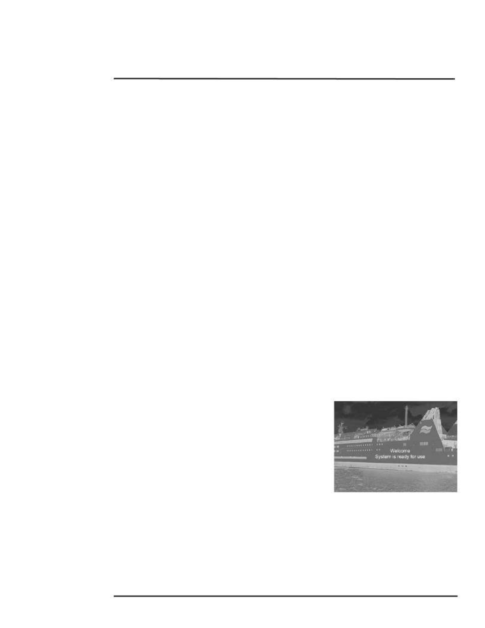
Powering the Camera
During bootup, a series of screens are shown as various
components are activated. How the screen looks will vary
depending on the particular configuration settings of your
installation. In general, the following sequence occurs:
1. If starting from a full shutdown, make sure the monitor is
turned on, then power on the system.
2. The FLIR splash screen is shown, then live video from the
visible camera is shown with boot progress indications.
3. When the bootup is complete (about 6 minutes), the
monitor shows the welcome message, and icons and the OSD menus are enabled.
Important: Do not turn on the JCU II until the message “Welcome System is ready for use” is
shown. Fully establishing a connection may take up to four minutes. Please be patient while the
system verifies each component.
August 2020

JCU II Power Menu
432-0012-01-10 Version 110 14
Powering the JCU II
When the JCU II is receiving power, the Power button will
be lit amber. When the button is pressed for
approximately three seconds, the JCU II will turn on and
search for cameras on the network.
On the LCD screen, Starting, then Searching… is
shown. When a camera is found, the message changes
to Connecting…, which continues to flash until the
process completes and is replaced by the camera ID,
such as M500. When more than one camera is found on
the network, the JCU II attempts to reconnect to the last
camera it was connected to, or if it has not connected to a
camera, it will prompt the user to select a camera.
JCU II Power Menu
The JCU II LCD screen generally shows the ID of the camera that is connected to the JCU II. The
various functions are accessed from a set of menus, with each menu entry selectable in the JCU II
display. When powered on and connected to a camera, pressing and holding the Power button
causes the JCU II to enter the Power Menu.
Use the JCU II joystick to scroll up and down (push fore
and aft), and select an entry by clicking the left joystick
button. (JCU II with newer software may use either the
left or right joystick button to select items in the power
menu.)
In the JCU II display, a down arrow (v) indicates you
can access additional menu choices by moving the
joystick down. An up arrow (^) indicates the last menu
entry is displayed, and the other choices must be
accessed by moving the joystick up. A double arrow
indicates you can move up or down in the menu.
Depending on the configuration of the camera network,
multiple cameras, or multiple JCU II, the Power Menu
can show the following menu options:
Assign JCU?
JCU Stndby?
Camera Stndby?
System Stndby?
Global Stndby?
Calibrate JCU?
Cancel
Standby States
When finished with the camera, Park the camera from the OSD menu to keep the system ready to
use at a moments notice on a command from the JCU II. When in Park mode, the system does not
generate a live video signal.
To initiate other standby modes, press and hold the Power button. After a brief countdown, the
Power Menu is shown. Scroll down with the joystick and press the left joystick button to select an
Power
LCD
screen
Select
camera
Scroll up
or down
August 2020

JCU II Power Menu
432-0012-01-10 Version 110 15
option from the menu. The menu options available will reflect the available hardware on the
camera network.
• JCU Stndby?—select to power down the JCU II.
• Camera Stndby?—select to power down the camera, leaving the JCU II powered
to connect to a different camera.
• System Stndby?—select to power down the camera and the JCU II.
• Global Stndby?—select to power down all the cameras and all the JCU II present on the
network.
Troubleshooting Tip: If the JCU II does not have power, it may be connected to a Power over
Ethernet (PoE) switch that has not been powered on, or it may be connected to a network switch
that does not provide PoE power.
Troubleshooting Tip: If this is the first time the JCU II has been used to connect to the camera, or
if the camera was not powered before the JCU II, v Select Camera is shown on the LCD
screen. Scroll down with the joystick to select a camera to control. When the ID of the camera
appears, press the left joystick button to select it. The camera ID will blink momentarily to indicate
it has been selected.
August 2020

432-0012-01-10 Version 110 16
3
M500 Joystick Control Unit
Introduction
The Joystick Control Unit (JCU II) is the primary method of
controlling the M500 camera. Use it to move the camera, zoom the
camera, switch between infrared and visible-light cameras, adjust
image settings, and access the on-screen menus.
This chapter describes how to use the JCU II buttons to operate the
camera features. Some of these features vary depending on the
specific way the system has been configured. Table 3.1 on page 19
summarizes the actions of each button.
Refer to the various configuration settings and how they affect
operation in Chapter 4, "M500 System Configuration," on page 20.
JCU II Joystick
The JCU II joystick can be moved left or right, forward and
back, and twisted in either direction. The joystick movement
is translated to control the pan/tilt position of the camera and
the zoom setting of the camera.
The right and left joystick buttons on the top of the joystick
are used to select and navigate when in the on-screen-
display menus and the JCU Power Menu.
Video Tracking—Use the right joystick button to enable and
engage video tracking with the M500 system. Use the left
joystick button to stop tracking.
Tilting the Camera
The camera has two tilt modes: Gaming and Pilot. When in Gaming mode (the default), moving
the joystick forward tilts the camera up; moving the joystick back tilts the camera down.
When in Pilot mode, moving the joystick forward causes the camera to tilt down; moving the
joystick back causes the camera to tilt up.
See “User Interface Menu” on page 28 for details about this settings.
Rotating the Camera
Use the joystick to rotate the camera to the left and right. Push the joystick to the right and the
camera will pivot to the right. Push the joystick to the left and the camera will pivot left.
Zooming the Camera
Twisting the joystick causes the camera to zoom in (clockwise) or zoom out (counterclockwise).
Back Enable/Engage
Video Tracking
August 2020

JCU II Buttons
432-0012-01-10 Version 110 17
JCU II Buttons
All of the buttons on the JCU II perform multiple functions. In most cases, each performs one
function when it is pressed briefly (short press) and a different function when it is pressed and held
(long press). The descriptions of the buttons in this section assume that the JCU II is powered on
(not in standby) and connected to an M500 camera system.
Power Button
Short Press—When the JCU II is powered on, a short
press of the Power button cycles through the four levels of
brightness (including off) for the JCU II display. The JCU II
controls are back lit to make them easier to see at night.
Use this button to adjust the brightness of the back lighting.
Long Press—When the JCU II is in standby, pressing and
holding the Power button is used to “wake up” the camera.
When the JCU II is powered on, it is used to access the
JCU II Power Menu to perform functions such as selecting
another camera or placing the system in standby. Refer to
“JCU II Power Menu” on page 14.
Menu Button
Press the Menu button to access the system on-screen-display (OSD) menus. In most cases,
there is no need to modify the factory default configuration settings of the system. Refer to “M500
System Configuration” on page 20.
When the OSD menu is shown, use the joystick up, down, left, and right to
navigate through the menu entries. The buttons on top of the joystick are
used as select and back buttons.
• Joystick Up – move up in a vertical menu
• Joystick Down – move down in a vertical menu
• Joystick Right/Left – move to the next menu or menu choice
• Menu – Exit Menu
• Right joystick button – select a menu or menu choice
• Left joystick button – back to the last menu or exit OSD menu
Home Button
Short Press—A short press of the Home button moves the camera to its
home position. The home position is a programmable preset position that
operators can use as a reference. When the Home button is pressed, the icon
is shown briefly on the video monitor.
Long Press—Pressing and holding the Home button sets the home position. First use the joystick
to point the camera’s line of sight to the a new home position. Press and hold the Home button
until the home symbol flashes on the video monitor; the new home position is set.
Standby
Powered on
Power button
Back Select
August 2020

JCU II Buttons
432-0012-01-10 Version 110 18
Scene Button—IR imaging only
The M500 thermal sensor automatically adjusts to changing
conditions providing optimized high-contrast images. The preset
automatic gain control (AGC) settings offer the most balance
and image quality for specific conditions. Experiment with the
different settings to find out which settings work best in different
conditions. The Scene button only effects the IR camera.
Short Press—A short press of the Scene button cycles through
the four preset AGC settings, which change the image gain and level settings. The icon for each
scene preset is shown on the video monitor display.
Color Button—IR Imaging only
Short Press—Pressing the Color button cycles through the preset color palettes of the active IR
camera. See “Color:” on page 24 for these additional options.
Long Press—Press and hold the Color button to invert the thermal camera video polarity (for
example, changing from black-hot to white-hot).
Focus Buttons
The M500 thermal camera can be focused either
manually or automatically. The visible-light camera
is always focused automatically.
The manual focus buttons are effective only when
the IR camera is the Active Camera.
the – button will move the focus nearer
the + button will move the focus farther away
During the manual focus operation, the OSD focus
bar will change accordingly.
Camera Button
Switch the Active Camera shown on the main video output. The buttons on the JCU II are effective
only on the Active Camera, except as noted.
User Buttons
The User buttons are programmable one-touch buttons to
access the most often used functions. Configure the short-press
action of this button from the User Programmable Button menu
entry (see page 29).
Short Press—User 1 – Auto Focus
User 2 – Stabilization on/off
User 3 – Spotlight
Long Press—Press and hold a user button to open the OSD menu to reprogram a function.
Night Harbor
Day Contrast
Manual focus
buttons
August 2020

JCU II Buttons
432-0012-01-10 Version 110 19
Display Camera and JCU II IP Address
Press the Color button while pushing the joystick forward; the IP address of the JCU II and then
the camera will display on the JCU II screen.
Button Summary
Table 3.1 summarizes the action of each button on the JCU II.
TABLE 3.1 Summary of Button Actions
Button Action
Color Short Cycle through the thermal palettes of the IR thermal imaging sensor.
Power Short Change JCU II back light illumination level
Power Long Display JCU II Power Menu
Home Short Return to home position
Home Long Set home to current position
Menu Short Display or exit menus
Scene Short Cycle through four preset scene settings
User 1 Auto Focus (can be reprogrammed)
User 2 Horizontal and Vertical Stabilization on/off (can be reprogrammed)
User 3 Spotlight on/off (can be reprogrammed)
Color + Joystick Forward Display JCU II and camera system IP address
Right Joystick Button When in OSD, select a menu or menu choice
Enable video tracking, then again to select a target
Left Joystick Button When in OSD, back to the last menu or exit OSD menu
Stop tracking a target or disable video tracking
August 2020

Main Menu
432-0012-01-10 Version 110 21
Immediate Action Menu Buttons
Some features are directly accessible from the main menu. Selecting one of the menu buttons
below invokes the action immediately and closes the OSD menu.
Tracker: When the Tracker is enabled pressing the Menu button will open the Tracker
contextual menu. You can set the Tracking box to show or not show when the Tracker is engaged
(actively tracking a target).
Park camera: the camera drives to its predefined Park position remaining fully active (no
Stand-by) except that the video is turned off. To exit Park and return to normal operation,
command a move with the joystick or press the Home button. The camera will return to Home
position. The Park position can be reconfigured by an admin user through the web browser
interface. See the M500 Installation Guide.
InstAlert/Exit InstAlert mode: When the camera is placed in InstAlert mode, a special
search palette is invoked so that a set percentage of the hottest temperatures in the image are
highlighted in Red-Orange shades, while colder temperatures are all in shades of gray. Especially
useful for locating people or running boats in the dark. After invoking the mode, pressing the Menu
button will show the InstAlert settings menu. The Highlight setting controls the percentage of the
hottest temperatures to display in Red-Orange.
IceAlert/Exit IceAlert mode: Conversely to InstAlert mode, when the camera is placed in
IceAlert mode, a special search palette is invoked so that a set percentage of the coldest
temperatures in the image are highlighted in Blue-Green shades, while warmer temperatures are
all in shades of gray. Especially useful for locating ice in the dark. After invoking the mode,
pressing the Menu button will show the IceAlert settings menu. The Highlight setting controls the
percentage of the coldest temperatures to display in Blue-Green.
August 2020

Main Menu
432-0012-01-10 Version 110 22
Surveillance: When the camera is in surveillance mode, it pans continuously left and right,
until it is taken out of surveillance mode or until the JCU II is used to move the camera. The
camera does not automatically resume panning; enable surveillance again by pressing a
programmed User button or selecting it again in the main menu.
When Surveillance is selected from the Settings menu or the Menu button on the JCU II is pressed
when in Surveillance mode, the following OSD menu is shown.
Scan Width: In surveillance mode, the Scan Width determines the range of horizontal azimuth
(pan) covered by each scan. The choices are:
Small: The camera scans from approximately 20o left and right of center
(40o total).
Medium: The camera scans from approximately 40o left and right of center
(80o total).
Large: The camera scan covers 80o to the left and right of center
(160o total). The default scan width is wide.
Note: The center of the scan pattern is determined by the direction the camera is pointing when
surveillance is enabled. The scan pattern is not centered about the home position, unless the
camera is in the home position when surveillance is enabled.
Scan Speed: In surveillance mode, the scan speed determines how quickly the camera scans
back and forth. The choices are fast, medium, and slow. The scan speed is affected by the zoom
state (scans at a slower rate when zoomed in).
NMEA: Select this option to enable or disable the processing of messages using the NMEA
interface. The factory default setting is disabled. All messages are ignored when NMEA Mode is
disabled even if the specific message types are enabled. See “NMEA Settings” on page 30.
Spotlight: Select this option and then select one of the active spotlight modes (On, Flash,
SOS). The Spotlight turns on in the selected mode. A user programmable button (UPB) can be
programmed as Spotlight on/off or as Signal Light to control the light. When set to Signal Light, the
UPB will turn on the Spotlight when pressed and turn off the Spotlight when released.
August 2020

Main Menu
432-0012-01-10 Version 110 23
Image and Settings Configuration Menus
The final three main menu buttons provide choices for system settings and information.
Image... See “Image Menu” on page 24.
Settings… See “Settings Menu” on page 25.
Help… Refer to the help menus for camera operation and
configuration information.
User guide...
About…
End of menu symbol
Menu will loop to
the other end
About…User guide...
August 2020

Image Menu
432-0012-01-10 Version 110 24
Image Menu
When Image is selected from the main menu, the following OSD menu items are shown.
Polarity—IR camera only: Inverts the colors representing hot and cold
in the infrared imagery. When using the IR camera the color palettes
described below are available. Inverting the polarity reverses the color map
of the thermal image.
Stabilization: Off, Vertical, Horiz & vertical
Select this option to enable or disable the two-axis mechanical gyro
stabilization. Gyro Stabilization is automatically turned off when the camera
in Park mode or in standby, but the system restores the setting when the
camera is returned to service.
Autofocus
This button causes the DLTV camera to toggle the autofocus mode. Clicking
the button a second time reinstates the autofocus mode and causes an
autofocus operation. This button causes the IR camera with a zoom lens to
perform an autofocus operation.
Color: Grayscale, Redscale, Fusion
Cycle through the available color palettes. Inverting the polarity reverses the
color map of the thermal image.
Color Palette Polarity Inverted
Grayscale White-Hot Black-Hot
Redscale Red-Hot Red-Cold
Fusion Fusion Fusion-Invert
Color Palette Polarity Inverted
Grayscale White-Hot Black-Hot
August 2020

Settings Menu
432-0012-01-10 Version 110 25
VIS low light mode: On/Off
Select this option to turn On/Off VIS low light mode. This function
works in conjunction with the setting of the Advanced image low
light mode (refer to “Advanced Image Menu” on page 27). If the
advanced setting is Auto, this button will only change the state of
the low light mode for about 5 seconds.
IR/Daylight zoom link: On/Off
When the zoom link is off, the active camera zoom setting will not
affect the zoom setting of the secondary camera.
Mirrored view: On/Off
Select this option to revert the video image which makes the scene
appear as if viewed in a mirror.
Settings Menu
When Setup is selected from the main menu, the following OSD menu is shown.
Save current settings as start-up defaults: Select this option to store the current camera
settings described below for start-up or anytime Restore settings from defaults is selected.
Restore settings from defaults: Revert to the stored values of the following settings.
Advanced image... See “Advanced Image Menu” on page 27.
User interface… See “User Interface Menu” on page 28.
Redscale Red-Hot Red-Cold
Fusion Fusion Fusion-Invert
Active Camera Scene Color
Home position Polarity Stabilization
Icon display Help text Mirrored View
Joystick mode UPB assignments NMEA auto movement settings
InstAlert settings IceAlert settings
Color Palette Polarity Inverted
August 2020

Settings Menu
432-0012-01-10 Version 110 26
Surveillance… See “Surveillance:” on page 22.
NMEA… See “NMEA Settings” on page 30.
Calibration & diagnostics Menu
IR test pattern: (On/Off)
Activate spotlight test: Click to run.
Activate pan and tilt test: Click to run.
Reset IR Lens: Click to run.
Set Az & El zero reference: Icons on the video show the direction the camera is facing in
relation to an outline of a ship. The M500 camera has a “forward” direction adjustment which has
been set at the factory. After the camera is installed, both the azimuth and elevation should be set
to account for variations required during installation so that the icons on the video show the
expected angular position of the camera. The azimuth direction should be directly toward the front
of the vessel; the elevation may be set to the horizon or another user preferred reference.
1. Using the JCU II, point the camera directly ahead and choose an elevation reference point.
For example, place the horizon in the center of the video.
2. Press the Menu button to turn the OSD menu on.
3. Navigate to Set-up Menu, Calibration &
diagnostics…, then select Set Az & El zero
reference.
4. Select Set origin to set the azimuth and elevation
offsets.
5. Verify that the icons on the video correspond to the
direction the camera is pointing.
August 2020

Settings Menu
432-0012-01-10 Version 110 27
Advanced Image Menu
IR eZoom, VIS eZoom: (On/Off)
The IR camera will extend past the 14x optical zoom with an additional
8x eZoom (to 112x). After the lens reaches the maximum optical zoom,
the zoom scale shown on the display changes as shown at the right.
The scale will change back to 14x when the eZoom is decreased to
zero.
The visible camera will extend past the 30x optical zoom with an
additional 12x eZoom (to 360x). The VIS eZoom and scale when the
visible camera is selected works in a similar manner as the IR camera.
VIS low light mode: (Auto/Manual)
When set to manual, use the VIS low light mode button on the Main menu to turn low light mode
On/Off. When set to Auto, this setting will override the Main menu button within about five seconds
(refer to “VIS low light mode:” on page 25).
VIS wide dynamic range: (On/Off)
When set to On, image processing provides clearer, more detailed images in high-contrast or
backlit environments by enhancing shadows and blown-out highlights in accordance with the
intensity difference.
VIS electronic stabilization: (On/Off)
When set to On, image processing compensates for camera vibration by slightly decreasing the
image near the edges of the frame allowing a centered image to appear more stable.
VIS defog: (On/Off)
When set to On, a foggy or low contrast scene will appear clearer.
eZoom
Optical
zoom
August 2020

Settings Menu
432-0012-01-10 Version 110 28
InstAlert highlight, IceAlert highlight (0 – 100)
The highlight settings control the range of temperatures to show colored. The hottest range of
temperatures will be shown in red when in InstAlert mode (InstAlert highlight) and the coldest
range of temperatures will be shown in blue when in IceAlert mode (IceAlert highlight). All other
temperatures are shown in grayscale.
To change a numeric setting, using IceAlert for example:
1. Select IceAlert highlight with the right joystick
button.
2. Twist or move the joystick left or right to change
the value.
3. Set the value by clicking the right joystick button.
Navigating away from the menu item before
setting the value will reset it to the previous setting.
IR cooler: (On/Off)
The IR cooler requires approximately six minutes to cool the thermal sensor before IR video is
usable. If the IR video is not required as an instant on featur ra is not going to e and if the IR came
be used for an extended period of time (4 - 6 hours), the cooler should be turned off to lower power
usage and extend the cooler lifetime.
User Interface Menu
Interface Language: (English/Espanol/Türkҫe) Set the language used in the OSD menu,
display icons, and help text.
Display icons: Minimal, Custom, Full
Selecting Minimal turns off most of the on-screen icons except when their corresponding controls
are actively in use. The pan position (azimuth) icon, tilt (elevation) position icon, and the FLIR logo
are always displayed. Other icons such as home and scene display on the screen only
momentarily when they are changed. Selecting Full maximizes the display of the on-screen icons.
Some icons such as home are only displayed momentarily. Refer to M500 Installation Guide for
configuring which icons are selected in each setting.
August 2020
Produkt Specifikationer
| Mærke: | FLIR |
| Kategori: | Overvågningskamera |
| Model: | M500 |
Har du brug for hjælp?
Hvis du har brug for hjælp til FLIR M500 stil et spørgsmål nedenfor, og andre brugere vil svare dig
Overvågningskamera FLIR Manualer

13 September 2024
8 September 2024
4 September 2024
2 September 2024
25 August 2024
25 August 2024
19 August 2024
18 August 2024
15 August 2024
13 August 2024
Overvågningskamera Manualer
- Overvågningskamera Bosch
- Overvågningskamera Denver
- Overvågningskamera Sony
- Overvågningskamera Canon
- Overvågningskamera Netis
- Overvågningskamera Samsung
- Overvågningskamera Panasonic
- Overvågningskamera Extech
- Overvågningskamera Moog
- Overvågningskamera TP-Link
- Overvågningskamera Philips
- Overvågningskamera Vitek
- Overvågningskamera Gigaset
- Overvågningskamera Pioneer
- Overvågningskamera Mitsubishi
- Overvågningskamera Braun
- Overvågningskamera Logitech
- Overvågningskamera Emos
- Overvågningskamera Google
- Overvågningskamera Technaxx
- Overvågningskamera HP
- Overvågningskamera Waeco
- Overvågningskamera Garmin
- Overvågningskamera Sanyo
- Overvågningskamera Grundig
- Overvågningskamera D-Link
- Overvågningskamera Arlo
- Overvågningskamera Motorola
- Overvågningskamera Asus
- Overvågningskamera Toshiba
- Overvågningskamera Pyle
- Overvågningskamera Kodak
- Overvågningskamera Furrion
- Overvågningskamera InFocus
- Overvågningskamera Nedis
- Overvågningskamera Friedland
- Overvågningskamera Abus
- Overvågningskamera Planet
- Overvågningskamera Adj
- Overvågningskamera Hama
- Overvågningskamera Creative
- Overvågningskamera Thomson
- Overvågningskamera Belkin
- Overvågningskamera Edimax
- Overvågningskamera Burg Wächter
- Overvågningskamera Clas Ohlson
- Overvågningskamera DataVideo
- Overvågningskamera Strong
- Overvågningskamera TRENDnet
- Overvågningskamera Smartwares
- Overvågningskamera Trevi
- Overvågningskamera Trust
- Overvågningskamera Laserliner
- Overvågningskamera Blaupunkt
- Overvågningskamera JVC
- Overvågningskamera Honeywell
- Overvågningskamera Uniden
- Overvågningskamera Buffalo
- Overvågningskamera Linksys
- Overvågningskamera Megasat
- Overvågningskamera Cisco
- Overvågningskamera EZVIZ
- Overvågningskamera König
- Overvågningskamera Elro
- Overvågningskamera Gembird
- Overvågningskamera Powerfix
- Overvågningskamera Alpine
- Overvågningskamera Netgear
- Overvågningskamera Maginon
- Overvågningskamera Yale
- Overvågningskamera Withings
- Overvågningskamera Nest
- Overvågningskamera Kerbl
- Overvågningskamera Vtech
- Overvågningskamera Exibel
- Overvågningskamera Genie
- Overvågningskamera Vaddio
- Overvågningskamera Bresser
- Overvågningskamera Western Digital
- Overvågningskamera Anker
- Overvågningskamera Digitus
- Overvågningskamera Zebra
- Overvågningskamera Jensen
- Overvågningskamera Alecto
- Overvågningskamera Flamingo
- Overvågningskamera Rollei
- Overvågningskamera Olympia
- Overvågningskamera Xiaomi
- Overvågningskamera Niceboy
- Overvågningskamera Aiptek
- Overvågningskamera Schneider
- Overvågningskamera B/R/K
- Overvågningskamera Marmitek
- Overvågningskamera Tesla
- Overvågningskamera Imou
- Overvågningskamera Ricoh
- Overvågningskamera Nexxt
- Overvågningskamera Aida
- Overvågningskamera APC
- Overvågningskamera Foscam
- Overvågningskamera Lorex
- Overvågningskamera Ikan
- Overvågningskamera Velleman
- Overvågningskamera LevelOne
- Overvågningskamera Marshall
- Overvågningskamera Perel
- Overvågningskamera Swann
- Overvågningskamera Vivotek
- Overvågningskamera Joblotron
- Overvågningskamera JUNG
- Overvågningskamera ORNO
- Overvågningskamera Binatone
- Overvågningskamera ZyXEL
- Overvågningskamera Fortinet
- Overvågningskamera Netatmo
- Overvågningskamera Tenda
- Overvågningskamera Eufy
- Overvågningskamera Ring
- Overvågningskamera M-e
- Overvågningskamera Overmax
- Overvågningskamera Somfy
- Overvågningskamera Y-cam
- Overvågningskamera Hikvision
- Overvågningskamera Monacor
- Overvågningskamera ION
- Overvågningskamera Raymarine
- Overvågningskamera Ubiquiti Networks
- Overvågningskamera AVerMedia
- Overvågningskamera EnGenius
- Overvågningskamera Reolink
- Overvågningskamera Grandstream
- Overvågningskamera Trebs
- Overvågningskamera EVE
- Overvågningskamera Renkforce
- Overvågningskamera Marshall Electronics
- Overvågningskamera Manhattan
- Overvågningskamera SPC
- Overvågningskamera Caliber
- Overvågningskamera Pentatech
- Overvågningskamera Switel
- Overvågningskamera AVtech
- Overvågningskamera LogiLink
- Overvågningskamera Orion
- Overvågningskamera Eminent
- Overvågningskamera Kramer
- Overvågningskamera QSC
- Overvågningskamera Hanwha
- Overvågningskamera Brilliant
- Overvågningskamera Lanberg
- Overvågningskamera Hive
- Overvågningskamera Siedle
- Overvågningskamera BirdDog
- Overvågningskamera Evolveo
- Overvågningskamera Genius
- Overvågningskamera KJB Security Products
- Overvågningskamera Valueline
- Overvågningskamera Provision-ISR
- Overvågningskamera Quantum
- Overvågningskamera Axis
- Overvågningskamera ACTi
- Overvågningskamera CRUX
- Overvågningskamera Avanti
- Overvågningskamera Vimar
- Overvågningskamera Aluratek
- Overvågningskamera Dahua Technology
- Overvågningskamera Chacon
- Overvågningskamera SereneLife
- Overvågningskamera ZKTeco
- Overvågningskamera AG Neovo
- Overvågningskamera Stabo
- Overvågningskamera EtiamPro
- Overvågningskamera First Alert
- Overvågningskamera Speco Technologies
- Overvågningskamera Boss
- Overvågningskamera Broan
- Overvågningskamera Conceptronic
- Overvågningskamera Avidsen
- Overvågningskamera Crestron
- Overvågningskamera Lindy
- Overvågningskamera Kogan
- Overvågningskamera AVMATRIX
- Overvågningskamera Delta Dore
- Overvågningskamera Promise Technology
- Overvågningskamera Sitecom
- Overvågningskamera DiO
- Overvågningskamera Minox
- Overvågningskamera Intellinet
- Overvågningskamera V-TAC
- Overvågningskamera Qian
- Overvågningskamera August
- Overvågningskamera IDIS
- Overvågningskamera Geovision
- Overvågningskamera Schwaiger
- Overvågningskamera Steren
- Overvågningskamera Elmo
- Overvågningskamera AViPAS
- Overvågningskamera UniView
- Overvågningskamera Equip
- Overvågningskamera Alfatron
- Overvågningskamera REVO
- Overvågningskamera Aqara
- Overvågningskamera Ernitec
- Overvågningskamera Setti+
- Overvågningskamera BZBGear
- Overvågningskamera PTZ Optics
- Overvågningskamera AVer
- Overvågningskamera Ferguson
- Overvågningskamera Moxa
- Overvågningskamera Inovonics
- Overvågningskamera Bea-fon
- Overvågningskamera Profile
- Overvågningskamera WyreStorm
- Overvågningskamera Allnet
- Overvågningskamera Aldi
- Overvågningskamera Airlive
- Overvågningskamera Aritech
- Overvågningskamera ACME
- Overvågningskamera KlikaanKlikuit
- Overvågningskamera Marquant
- Overvågningskamera Ednet
- Overvågningskamera Lumens
- Overvågningskamera Hombli
- Overvågningskamera Naxa
- Overvågningskamera Miniland
- Overvågningskamera Xavax
- Overvågningskamera Gira
- Overvågningskamera Interlogix
- Overvågningskamera DSC
- Overvågningskamera Boyo
- Overvågningskamera Iget
- Overvågningskamera EverFocus
- Overvågningskamera Adesso
- Overvågningskamera Satel
- Overvågningskamera Notifier
- Overvågningskamera Monoprice
- Overvågningskamera Beafon
- Overvågningskamera Chuango
- Overvågningskamera MicroView
- Overvågningskamera ETiger
- Overvågningskamera Videcon
- Overvågningskamera INSTAR
- Overvågningskamera Advantech
- Overvågningskamera Digital Watchdog
- Overvågningskamera Moen
- Overvågningskamera Ganz
- Overvågningskamera MEE Audio
- Overvågningskamera Mobotix
- Overvågningskamera Kwikset
- Overvågningskamera Ikegami
- Overvågningskamera Leviton
- Overvågningskamera Pelco
- Overvågningskamera Approx
- Overvågningskamera ClearOne
- Overvågningskamera Ebode
- Overvågningskamera Oplink
- Overvågningskamera Dorr
- Overvågningskamera Sonic Alert
- Overvågningskamera Linear PRO Access
- Overvågningskamera Summer Infant
- Overvågningskamera SMC
- Overvågningskamera Topica
- Overvågningskamera Iiquu
- Overvågningskamera Verint
- Overvågningskamera Brinno
- Overvågningskamera Rostra
- Overvågningskamera Caddx
- Overvågningskamera Spyclops
- Overvågningskamera EKO
- Overvågningskamera Kguard
- Overvågningskamera Woonveilig
- Overvågningskamera Accsoon
- Overvågningskamera Mobi
- Overvågningskamera Surveon
- Overvågningskamera Hollyland
- Overvågningskamera Epcom
- Overvågningskamera Indexa
- Overvågningskamera Lutec
- Overvågningskamera Whistler
- Overvågningskamera ClearView
- Overvågningskamera VideoComm
- Overvågningskamera IMILAB
- Overvågningskamera 3xLOGIC
- Overvågningskamera Inkovideo
- Overvågningskamera Weldex
- Overvågningskamera SecurityMan
- Overvågningskamera Mach Power
- Overvågningskamera Canyon
- Overvågningskamera CNB Technology
- Overvågningskamera Tapo
- Overvågningskamera Aigis
- Overvågningskamera Exacq
- Overvågningskamera Brickcom
- Overvågningskamera Laxihub
- Overvågningskamera Securetech
- Overvågningskamera EFB Elektronik
- Overvågningskamera NetMedia
- Overvågningskamera Videotec
- Overvågningskamera Illustra
- Overvågningskamera Atlona
- Overvågningskamera Nivian
- Overvågningskamera Arenti
- Overvågningskamera E-bench
- Overvågningskamera Blow
- Overvågningskamera Syscom
- Overvågningskamera Tecno
- Overvågningskamera Night Owl
- Overvågningskamera Guardzilla
- Overvågningskamera Astak
- Overvågningskamera Blink
- Overvågningskamera Milestone Systems
- Overvågningskamera Zavio
- Overvågningskamera Campark
- Overvågningskamera IPX
- Overvågningskamera Dedicated Micros
- Overvågningskamera Hamlet
- Overvågningskamera Annke
- Overvågningskamera Qoltec
- Overvågningskamera Digimerge
- Overvågningskamera Feelworld
- Overvågningskamera Wisenet
- Overvågningskamera Infortrend
- Overvågningskamera Epiphan
- Overvågningskamera HiLook
- Overvågningskamera Compro
- Overvågningskamera Vimtag
- Overvågningskamera Sonoff
- Overvågningskamera Gewiss
- Overvågningskamera Alula
- Overvågningskamera Insteon
- Overvågningskamera Costar
- Overvågningskamera ALC
- Overvågningskamera Security Labs
- Overvågningskamera Comtrend
- Overvågningskamera Seneca
- Overvågningskamera Avigilon
- Overvågningskamera American Dynamics
- Overvågningskamera Vosker
- Overvågningskamera Sentry360
- Overvågningskamera Owltron
- Overvågningskamera Petcube
- Overvågningskamera Enabot
- Overvågningskamera Luis Energy
- Overvågningskamera Sir Gawain
- Overvågningskamera VisorTech
- Overvågningskamera Atlantis Land
- Overvågningskamera B & S Technology
- Overvågningskamera I3International
- Overvågningskamera Ecobee
- Overvågningskamera Turing
- Overvågningskamera Wasserstein
- Overvågningskamera Qolsys
- Overvågningskamera Control4
- Overvågningskamera Milesight
- Overvågningskamera GVI Security
- Overvågningskamera Conbrov
- Overvågningskamera HuddleCamHD
- Overvågningskamera Defender
- Overvågningskamera IOIO
- Overvågningskamera BIRDFY
- Overvågningskamera I-PRO
- Overvågningskamera DVDO
- Overvågningskamera TCP
- Overvågningskamera Bolin Technology
- Overvågningskamera Nextech
- Overvågningskamera Tuya
- Overvågningskamera Bolide
- Overvågningskamera Telycam
- Overvågningskamera Arecont Vision
- Overvågningskamera Schlage
Nyeste Overvågningskamera Manualer
7 April 2025
7 April 2025
6 April 2025
29 Marts 2025
28 Marts 2025
20 Marts 2025
20 Marts 2025
20 Marts 2025
13 Marts 2025
8 Marts 2025