Geovision GV-SNVR1612 Manual
Læs nedenfor 📖 manual på dansk for Geovision GV-SNVR1612 (137 sider) i kategorien VCR. Denne guide var nyttig for 13 personer og blev bedømt med 4.5 stjerner i gennemsnit af 2 brugere
Side 1/137

SNVR-UM-K

i
Preface
Welcome to the GV-SNVR System User’s Manual.
The GV-SNVR system has a series of models designed to meet dierent needs.
This manual is designed for the following models:
Models
GV-SNVR0400F
GV-SNVR0411
GV-SNVR0412
GV-SNVR0811
GV-SNVR0812
GV-SNVR1600
GV-SNVR1611
GV-SNVR1612
Caution
⚫ The GV- system designed for indoor use only. SNVR is
3
˙ Recording export
˙ Remote live view rough Web browser th
˙ PTZ control using GV-Joystick V2 or on-screen p anel
˙ HDD Storage
Model
Storage
GV-SNVR04 / 0811 11
1 SATA HDD drawer (3.5”) for up to 8 TB storage
GV- 0412 / SNVR 0812
1 SATA HDD drawer (3.5”) for up to 10 TB s rage to
GV-SNVR040 0F
1 S A HDD draAT wer (3.5”) for up to 4 TB stora ge
GV- SNVR1600
4 SATA HDD drawers (3.5”) for up to 16 TB storage
GV-SNVR1611 / 1612
2 SATA HDD drawers (3.5 ) for up to 20 TB storage ”
˙ Smart device access (iOS and Android)
˙ Support for l s (13 languages for GV-S R0400F / 1 )14 anguage NV 600
Note: Main Stream and Sub Stream resolutions for compatible IP cameras must both fulll
the specications listed in . Appendix C
1.2 Models
GV-SNVR has the following models:
GV-SNVR0400F
GV-SNVR04 11
GV-SNVR0412
- Support 1 SATA HDD ( 5 ) 3. ”
- Record up to 4 IP channels
GV-SNVR0811
GV-SNVR0812
- Support 1 SATA HDD (3.5 ) ”
- Record up to 8 IP channels
GV-SNVR1600
- Support 4 SATA . HDD (3 5”)
- Record up to 16 IP channels
GV-SNVR1611
GV-SNVR1612
- Support 2 SATA HDD (3.5”)
- Record up to 16 IP channels
1.3 cking List and Package Pa
You can choose to purchase a single GV-SNVR package, or a GV-SN bundled VR0400F
package that includes 4 GV-Target IP Cameras of your choice with or without a GV-PoE , and
switch.

Introduction
4
1
1.3.1 GV- Single Package SNVR
GV-SNVR0400F
1. GV-S NVR0400F
2. power cord AC
3. AC/DC adapter
(DC 19V, 3.42A, 65 W)
4. Screw x 6 (for H ) DD
5. SATA cable
6. Download Guide
7. Quick Start Guide
GV-SNVR0411
1. GV- R04 SNV 11
2. powe cord AC r
3. da AC/DC a p r te
(DC V, 1.38 A, 72 52 W)
4. SATA c able
5. power cable HDD
6. Screw x 4 (for HDD)
7. Rubber foot x 4 (for HDD)
8. mouse USB
9. load Guide Down
5
GV-SNVR0412
1. GV-SNVR0412
2. AC Power cord
3. AC/DC adapter
(DC 48 V, 1. A, 35 65 W)
4. SATA cab le
5. HDD power cable
6. rew x 4 (for HDD) Sc
7. mouse USB
8. Foam foot
9. Rack mount kit (2 L-shaped
brackets + 4 screws)
10. Downl Guide oad
GV-SNVR0811
1. GV- 8 SNVR0 11
2. AC Power cord
3. AC/DC adapter
(DC 56V, 2.32 A, 130 W)
4. SATA cable
5. power cable HDD
6. Screw x 4 (for HDD)
7. mouse USB
8. Download Guide

Introduction
6
1
GV-SNVR 0812
1. GV- SNVR0812
2. power cord AC
3. AC/DC adapter (DC 52V,
1.8A, 100W)
4. SATA cable
5. power cable HDD
6. Screw x 4 (for HD D)
7. oot fFoam
8. B mouse US
9. 2 Rack mount kit ( L-shaped
brackets + 4 screws)
10. Download Guide
GV-SNVR1600
1. GV- SNVR1600
2. power cord AC
3. SATA cable x 4
4. mounting bracket kit (4 HDD
pairs and 32 screws included)
5. Rack mount kit (2 L-shaped
brackets and 6 screws
i luded) nc
6. Rubber foot x 4
7. mouse USB
8. Download Guide
9. Quick Start Guide

7
GV-SNVR1611
1. GV-SNVR16 11
2. power cord AC
3. SATA cable x 2
4. power cable x 2 HDD
5. Screw x 8 (for HDD)
6. oo fFoam t
7. mouse USB
8. Download Guide
GV-SNVR1612
1. GV-SNVR1612
2. er Pow adapter
3. power cord AC
4. SATA cable x 2
5. power cable x 2 HDD
6. Screw x 8 (for HDD)
7. oot fFoam
8. ous USB m e
9. Download Guide

Introduction
8
1
1.3.2 GV- VR Bundled Package SN
GV-SNVR0400F
1. GV- 0 package x 1 SNVR 400F
2. Target IP Camera x 4
3. GV-POE0400 x 1
Note: For the Target IP Camera, select any 4 models from GV-EBL1100 / 2100, GV-EBX1100 /
2100, GV-EDR1100 / , -EFD1100 / 2100 Contact your dealer for more information.2100 GV .
9
1.4 Compatible Products a System Requirements nd
1.4.1 Supported GV-IP Cameras
GV- compatible with the following SNVR is GV-IP Cameras:
˙ GV-Target Series IP Cameras (Firmware V1.0 o l ) r ater
˙ GV-SD220/220-S (F mware V1.04 or later) ir
˙ GV-UNFE2503 / UNP2500 (Firmware V2.11 or later)
˙ her GV-IP CameAll ot ras EXCEPT for the models below:
GV- VR System SN
Not Supported Models
SNVR0400F
GV-ABD1300
GV-ABL Series / ADR Series / AVD Series / EBD Seri / TBL es
Series / TDR S ies / TVD Series er
GV-BX110/12201
GV-BL110
GV-EBL2101 / 2111 / 3101 (conditionally supported ) (*Note4)
GV-FD8700- FR
FER12203 12700 GV‐/
GV-Fisheye Cameras (conditionally supported) (*Note3)
GV-MFD110
GV-PT110
GV-PTZ010D
GV-SD010 / 200 / 2 -S / / - / 2411 / - / 00 2301 2322 IR 2722 IR
3732- IR
GV-VD8700
GV-VR360
SNVR1600
SNVR0411
GV- 1BX 10
GV-BL110
GV-FE520 / 521
GV-FER12203 / 12700
GV-MFD110
GV-PT110
GV-PTZ010D
GV-SD010
SNVR0412
SNVR08 11
SNVR0812
SNVR1611
SNVR1612

Introduction
10
1
Note: The live view of GV-SD200 / 200-S / 2411 / 2322-IR / 3732-IR can be accessed
through GV- 0411 / 0811, but their PTZ control functions are only available on SNVR
GV- 0411 rmware V2.61 or later and GV-SNVR0811 rmware V2.50 or later. SNVR
IMPORTANT:
1. - supports a recording frame rate of up to 30 fps. GV SNVR
2. -SNVR supports a total bandwidth of up to 50 Mbps f - , 40 Mbps GV or GV SNVR0400F
for -SNVR04 , 24 Mbps for -SNVR0412 80 Mbps for GV-SNVR0811GV 11 GV , , 48 Mbps
for GV-SNVR0812, Mbps for GV-SNVR1612, Mbps for 96 100 GV- and 320 SNVR1600
Mbps for GV-SNVR16 . 11
3. -SNVR1600 can only connect to GV GV-Fisheye Cameras, except for GV-FER12203 /
12700, via and does not support sheye dewarping(channel 1 *).
4. -EBL2101 / 2111 / 3101 is only supported on GV channel 1 of GV-SNVR0400F ( ). *
5. Fisheye dewarping is only supported by -SNVR / 0412 GV 0411 / 0811 0812. For /
details, see 2.8.5 F heye Dewarpingis . GV-SNVR1611 V3.11 only supports sheye
dewarping on GV- Viewer (V1.5.0001) SNVR .
6. For supported IP cameras, the resolutions of stream 1 and 2 both must meet the
requirements note in d Appendix C.
1.4.2 Supported GeoVision Applications
GV- compatible with the following applications: SNVR is
For GV- 0411 / 0811 SNVR
˙ GV-Edge Recording Manager (Windows Version V1.2.0.0 or later)
˙ GV-Control Center (V3.4.0.0 or later)
˙ GV-Center V2 (V15.10 or later)
˙ GV-Vital Sign Monitor (V15.10 or later)
˙ GV-Eye (V2.3 or later)
˙ GV-Cloud Center (V1.0 or later)

11
For GV- 08SNVR0412 /12
˙ GV-Edge Recording Manager (Windows Version V1.4 .3 / V1.4.0.0 or later for .0
GV- VR0412 / ) SN 0812
˙ GV-Control Center (V3.6.0 or later)
˙ GV-Center V2 (V18.2 + patch or later)
˙ GV-Vital Sign Monitor (V17.1 or later)
˙ GV-Eye (for iOS / Android V2. 2 or later) 7.
˙ GV-Cloud Center (V1.0 or later)
For GV- SNVR1612
˙ GV-Edge Recording Manager (Windows Version V2.1.0 or later)
˙ GV-Control Center (V3.4.0 or later)
˙ GV-Center V2 (V18.2 + patch or later)
˙ GV-Vital Sign Monitor (V16.11 or later)
˙ GV-Cloud Center (V1.0 or later)
˙ GV-Eye (V2.5.1 or later)
For GV- 1611 SNVR
˙ GV-Center V2 (V18.2 + patch or later)
˙ GV-Vital Sign Monitor (V16.11 or later)
˙ GV-Cloud Center (V1.0 or later)
˙ GV-Eye (V2.5.1 or later)
For GV- 4 / 16 SNVR0 00F 00
˙ GV- ge Recording Manager (Windows Version V1.1.0.0 or later) Ed
˙ GV-Control Center (V3.3.0.0 or later)
˙ GV-Center V2 (V15.10 or later)
˙ GV-Vital Sign Monitor (V15.10 or later)
˙ GV-Eye (V2.0 or later)

Introduction
12
1
1.4.3 System Requirements
Recommended Hard Di s sk
For system efciency, it is recommended to use enterprise-level hard disk drives instead of
desktop-level or green HDD. For tested hard disk drives, see Appendix.
Note: GV-SNVR does not support 2.5” SATA HDD.
Supported Web Browsers
Internet Explore 8 or lat (10 or later for -S ) r er GV NVR0412 / 0812
Google Chrome
Mozilla Firefox
Safari (Only for -SNVR0411 0412 / 0811 / 0812 / / 1612)GV / 1611
Microsoft Edge (Only for GV- / 0812 / 1612)SNVR0411 / 0412 / 0811 / 1611

13
1. al5 Option Accessories
Optional devices can expand your GV-SNVR’s capabilities and versatility. Contact your
dealer for more information.
GV-Joystick V2
GV-Joystick V2 facilitates PTZ camera control. It can be plugged
into GV- for independent use to empower the operation of SNVR
PTZ camer as.
GV-PO Switch E
GV-POE Switch is designed to provide power along with network
connection for IP devices. GV-PO Switch is available in various E
models with dierent numbers and types of ports.
GV-WiFi Adaptor V2
For GV- 411 / 0811 only, SNVR0 GV-W i Adaptor V2 is designed to iF
connect GV-IP devices to a wireless network. This product supports
wireless connections at 4 GHz and 5 GHz. 2.
Slide il Kit Ra
T Slide Rail Kit is used to mount a rail for he GV-SNVR1600 in a 19”
cabinet.

Introduction
14
1
1.6 Overview
1.6.1 GV-SNVR0411 Front View
4
3
2
1
Figure 1-2
No.
Name
Function
1
Power LED
Shows constant green when power is supplied.
2
HDD Error LED
Shows constant red when:
˙ No hard drive is installed.
˙ The hard drive is not formatted.
˙ The hard drive fails.
3
HDD LED
Blinks green when the HDD is writing or reading data.
4
USB 2.0 Port
Connects to a keyboard, mouse, USB ash drive, GV-WiFi Adaptor
V2 or GV-Joystick V2.
15
1.6.2 GV-SNVR0411 Rear View
6
1
4
2
53
Figure 1-3
N o.
Name
Function
1
DC 52 V (Power Input)
Connects to power supply.
2
Megabit Po Ports E
C ts to cameras, delivering er and net rk onnec pow wo
connection to the cameras .
3
WAN
Connects a network. to
4
USB 2.0 Port
Connects to key rd, mouse, USB ash drive, GV-WiFi a boa
Adaptor V2 or GV-Joystick V2.
5
Default Button
Restores the device to its fault settings. Press the button fode r
15 seconds to load default.
6
HDMI Output
Connects to a HD T V.
IMPORTANT: Only connect GV-SNVR04 to the Internet through its 11 WAN Port (No. 3) as
opposed to any of the 4 PoE ports (No. 2), as they ar only f connecting to IP cameras ande or
have limited network connecti on.

Introduction
16
1
1.6.3 GV-SNVR0400F Front View
1 2 3 4 51 6
Figure 1-4
N o.
Name
Function
1
USB 2.0 Port
Connects to a keyboard, mouse, USB ash drive or GV-Joystick V2.
2
Audio In
Not functiona l.
3
Audio Out
Connects to a speaker.
4
Power LED
Shows constant blue when power is supplied.
5
HDD Error LED
Shows constant red when:
˙ No hard drive is installed.
˙ The hard drive not formatted. is
˙ The hard drive fails.
6
Power Button
Turns on/off the power.

17
1.6.4 GV-SNVR0400F Rear View
123
5
4
Figure 1-5
No.
Name
Function
1
Gigabit Ethernet Port
Connects to a network.
2
HDMI Output
Connects to a HD TV.
3
USB 2.0 Port
Connects to keyboard, mouse, USB ash drive or a GV-Joystick
V2.
4
Default Button
Restores the d ice to default settings. Press the button for 15 ev
seconds to load default.
5
Power Input
Connects to power supply.

Introduction
18
1
1.6.5 GV-SNVR0811 Front View
134
2
Figure 1-6
No.
Name
Function
1
Power LED
Shows constant green when power is supplied.
2
HDD Error LED
Shows constant red when:
˙ No hard drive is install ed.
˙ The hard drive is not formatte d.
˙ hard drive fails. The
3
HDD LED
Blinks green when the HDD is writing or reading data.
4
PoE LED
Indicates the PoE port in use.
19
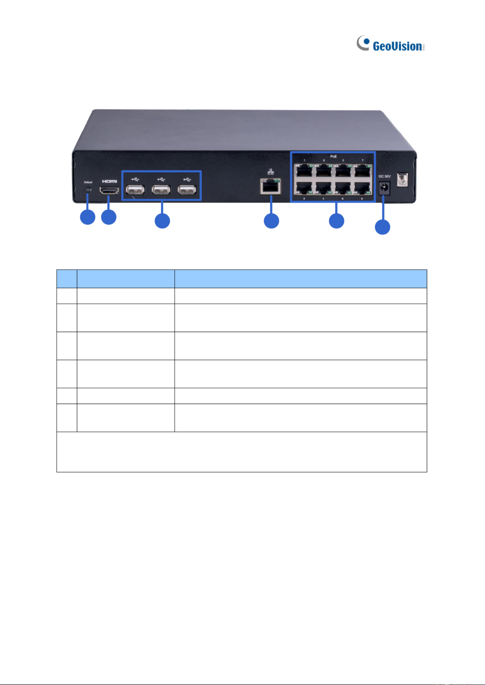
1.6.6 GV-SNVR0811 Rear View
1
234
56
Figure 1-7
No.
Name
Functio n
1
DC 52 V (Power Input)
Connects to power supply.
2
Megabit Po Ports E
Connects t cameras, delivering power and network o
connection to the cameras .
3
Network
Connects a network. The light on the left turns orange wheto n
connecting to Ethernet of 10 /100 Mbps.
4
USB 2.0 Port
Connects to key rd, mouse, U ash drive, GV-WiFi a boa SB
Adaptor V2 or GV-Joystick V2.
5
HDMI Outp ut
Connects to a HD TV.
6
Default Button
Restores the device to its default settings. Press the button for
15 seconds to load default.
IMPORTANT: Only connect GV- 0811 to the Internet through its SNVR WAN Port o. 3) as (N
opposed to any of the 8 PoE ports (No. 2), as they are only f connecting to IP cameras andor
have limited network connecti on.

Introduction
20
1
1.6.7 GV-SNVR1600 Front View
1
2
3
4
5
6
7
Figure 1-8
No.
Name
Function
1
Power Button
Turns on/off the power.
2
Power LED
Shows constan blue when power is supplied. t
3
HDD Status LED
Flashes blue when the hard drive is writing or reading data.
4
HDD Error LED
Shows constant red when:
˙ No hard drive is install ed.
˙ hard drive is not formatted. The
˙ The hard drive fails.
5
WAN LED
Flashes when the WAN port is receiving activity. blue
6
LAN LED
Flashes blue when the LAN port is receiving activity.
7
USB 2.0 Port
Connects to keyboard, mouse, USB ash drive or GV-Joystick V2.a
1.6.1.1

21
1.6.8 GV-SNVR1600 Rear View
1 2 3 4 5
6789
Fig e 1-9ur
No.
Name
Functio n
1
Audio Micro one I Port ph n
Not functional.
2
VGA Monitor Output
Connects to a VGA monitor.
3
HDMI Port
Connects to a HD TV.
4
USB 2.0 Port x 4
Connects to a keyboard, mouse ash drive or , USB
GV-Joystick V2.
5
Power Input
Connects to power supply.
6
Gigabit Ethernet Port (LAN)
Connects to a network.
7
Gigabit Ethernet rt (WAN) Po
Connects to a network.
8
Audio Line Out Port
Connects to a . headphone
9
Audio Line Out Port
Connects to speaker. a
Note: When the two Ethernet ports (No. 6 and No. 7) are used together, one i LAN port ands
the other is WAN port.

Introduction
22
1
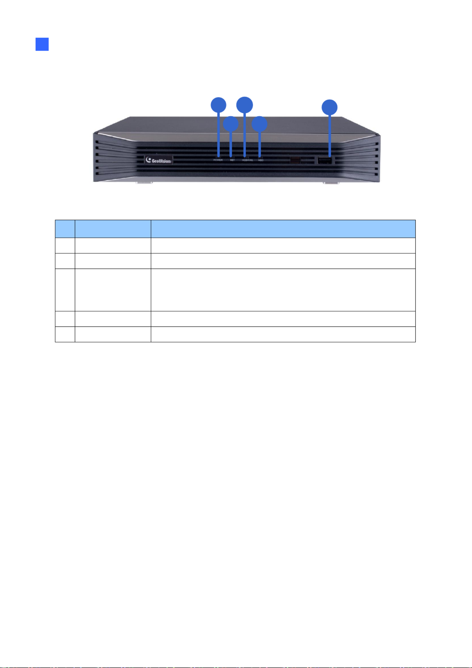
1.6.9 GV-SNVR16 Front View 11
1
1
1
11 3
3
3
33
4
4
4
44
2
2
2
22
5
5
5
55
Figu e 10r 1-
No.
Nam e
Function
1
HDD1 LED
Constant blue when HDD1 is writing or reading data.
2
HDD2 LED
Constant blue when HDD2 is writing or reading data.
3
HDD Fail LED
Shows constant r when or both of the hard drives is: ed one
˙ Not formatted.
˙ Fa s to read or write. il
4
P er LED ow
Shows constant blue en power is supplied. wh
5
USB 2.0 Port
Connects to a keyboard, mouse, USB ash drive or GV-Joystick V2.
23
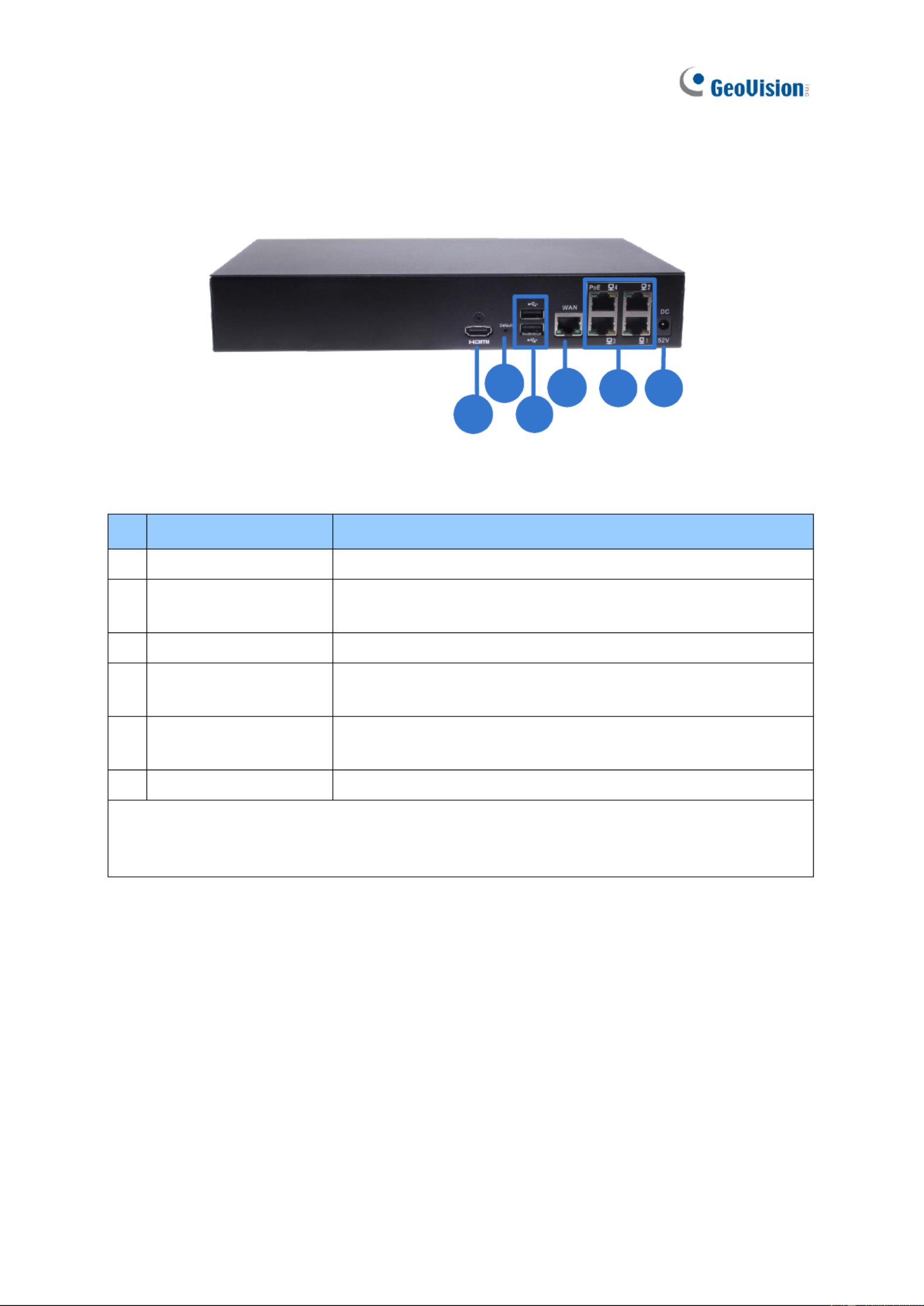
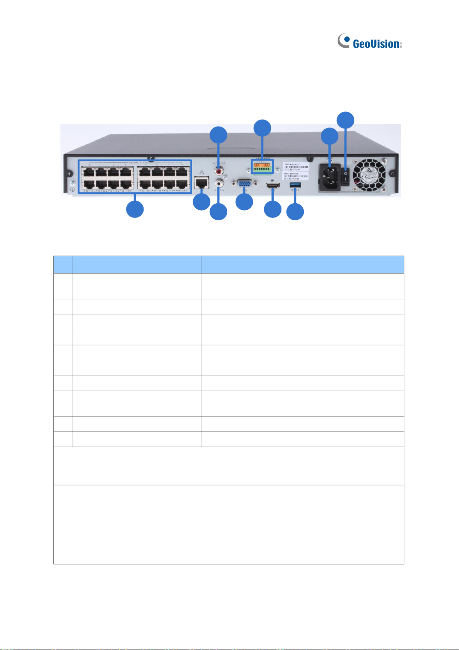
1.6. 10 GV-SNVR16 Rear View 11
1
1
1
11 2
2
2
22
3
3
3
33
4
4
4
44
5
5
5
55
6
6
6
66
7
7
7
77 8
8
8
88
9
9
9
99
10
10
10
1010
Figure 1-11
No.
Name
Function
1
M it PoE Ports egab
C ts to cameras, delivering er and network onnec pow
connection to the cameras.
2
Megabit hernet Port (WA Et N)
Connects to a network.
3
Audio Line In Port
Connects to a microphone.
4
Audio Line Out Port
Connects to speaker. a
5
VGA Output
Connects to a VGA monito r.
6
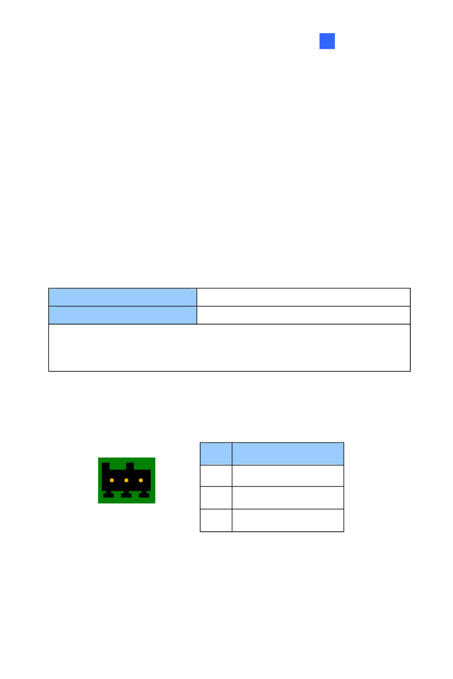
I/O Panel
Connects to 4 input and 1 output devices
7
HDMI O utput
Connects t a HD TV. o
8
USB 3.0 Port
Connects to keyboard, mouse, USB ash drive or a
GV-Joystick V2.
9
Power Input
Connects to power supply.
10
Power Button
Turns the system on or o.
IMPORTANT: Only connect GV- 1611 to the Internet through SNVR its WAN Port (No 2) a. s
opposed to any of the PoE ports (No. 1), as they are only f connecting to IP camer 16 or as
and have limited network connection.
Note: GV-SNVR1611 does not have a load fault button. To restore factory settings de
manually for:
˙ Firmware V3.09 or earlier, right-click the mouse ve times during the startup scre . en
˙ Firmware V3.10 or later, click both the left- and right-click of the m se 10 times within 3ou
seconds during the startup screen.
Or see 6.2.5 Restoring to Factory Default Settings for loading default via GV-IP Device Utility
Introduction
24
1
1.6.11 GV-SNVR 12 Front View 08
1
1
1
11 3
3
3
33
4
4
4
44
2
2
2
22
5
5
5
55
Figure 1-12
No.
Name
Function
1
Power LED
Shows constant blue when r is supplied. powe
2
Network LED
Shows constant blue when connected to a network.
3
HDD Fail LED
Shows constant red when the hard drive either: is
˙ Not formatted.
˙ Fails to read or write.
4
HDD LED
Shows constant blue when the hard drive is writing or re data.ading
5
USB 2.0 Port
Connects to a keyboard, mouse, USB ash drive or GV-Joystick V2.
25
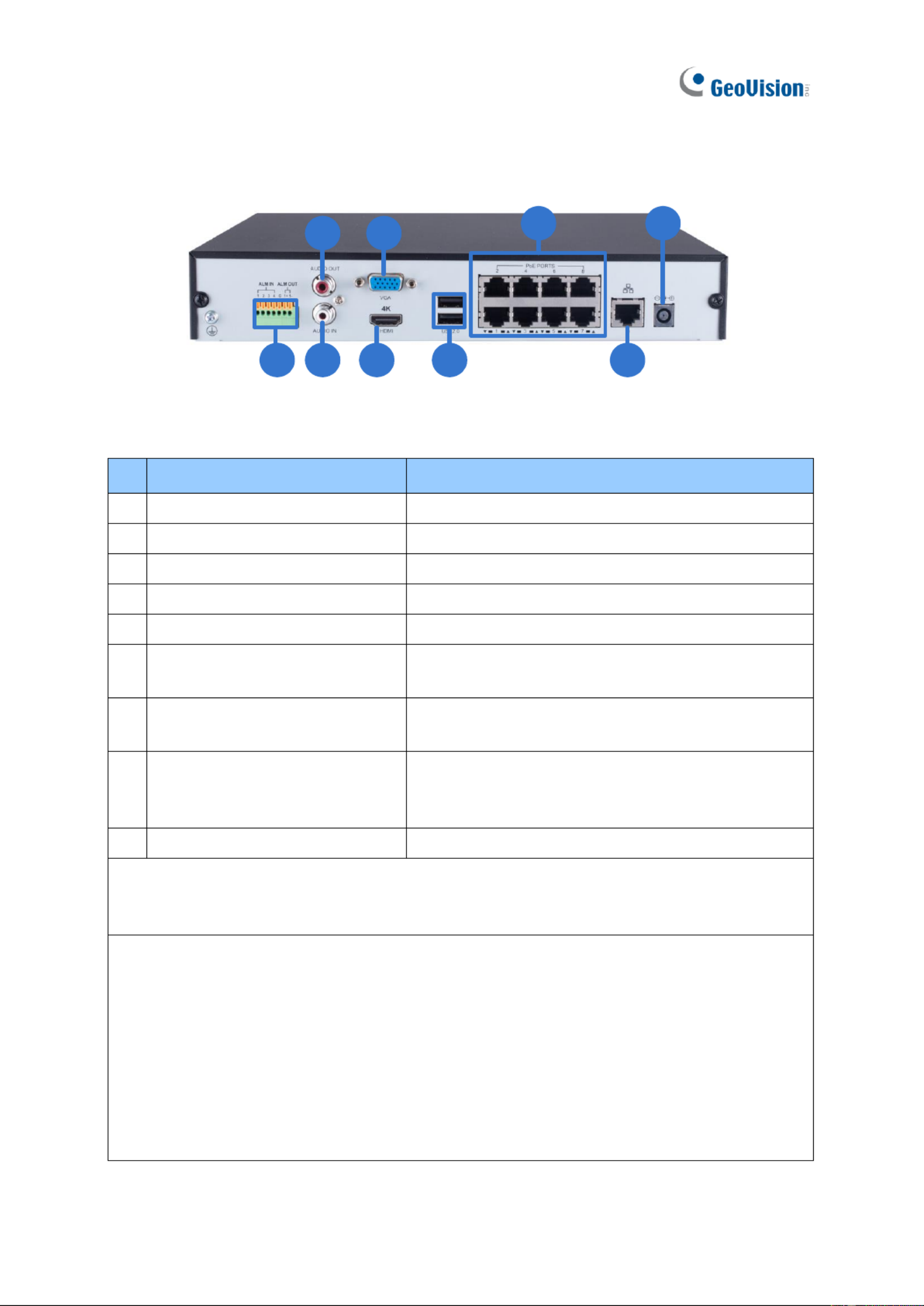
1.6.12 GV-SNVR 12 Rear View 08
2
2
2
22
3
3
3
33
4
4
4
44
1
1
1
11 6
6
6
66
5
5
5
55 7
7
7
77
8
8
8
88
9
9
9
99
Figure 1-13
No.
Name
Fun n ctio
1
I/O Panel
Connects to 4 input and 1 output devices
2
Audio Li Out Port ne
Connects to speaker. a
3
Audio Line In Port
Connects to a cropho . mi ne
4
HDMI Outp ut
Connects to a HD TV.
5
VGA Output
Connects to a VGA monitor.
6
USB 2.0 Port
Connects keyboard, mouse, B ash drive or to a US
GV-Joystick V 2.
7
Megabit PoE Ports
Connects to cameras, delivering power and network
connection to the came s. ra
8
Megabit Ethernet Port (WAN)
Connects a network. The light at the bottom to
ashes gre when c ecting to Ethernet of 10 en onn
/100 Mbps.
9
DC 52 V (Power In ) put
Co ts to power supply. nnec
IMPORTANT: Only connect GV-SNVR0812 to the Internet through its WAN Port o. 8) as (N
opposed to any of the 8 PoE ports (No. 7), as ey are y for connecting to IP cameras andth onl
have limited netw connection. ork
Note:
1. IP cameras connected t the PoE ports are provided network connection via an isolated o
network at is not bridged to, or inaccessible by, the WAN. th
2. IP cameras connected t the PoE o ports are assigned a channel number in accordance to
t PoE port number. he
3. GV- 0812 does not have a load default button. To restore factory settings manually SNVR
for rmware V1.10 or later, click both the left- and right-click of the mouse 10 time withins
3 seconds during the startup screen, or see 3.8 System or 6.2.5 Restoring to Factory
Default Settings for loading default through its UI or GV-IP vice Utility, respectively. De
Introduction
26
1
1.6.13 GV-SNVR0412 Front View
1
1
1
11 3
3
3
33
4
4
4
44
2
2
2
22
5
5
5
55
Figure 1-14
No.
Name
Function
1
Power LED
Shows constant blue when power is supplied.
2
Network LED
Shows c tant blue when connected to a network. ons
3
HDD Fail LED
Shows constant red when the hard drive is either:
˙ Not formatted.
˙ Fails to read or write.
4
HDD LED
Shows constant blue when the hard drive is writing or reading data.
5
USB 2.0 Port
Connects to a key rd, mouse, USB ash drive or GV-Joystick V2.boa
Produkt Specifikationer
| Mærke: | Geovision |
| Kategori: | VCR |
| Model: | GV-SNVR1612 |
Har du brug for hjælp?
Hvis du har brug for hjælp til Geovision GV-SNVR1612 stil et spørgsmål nedenfor, og andre brugere vil svare dig
VCR Geovision Manualer

3 September 2024
28 August 2024
28 August 2024
VCR Manualer
- VCR Bosch
- VCR Sony
- VCR Canon
- VCR Samsung
- VCR TP-Link
- VCR Philips
- VCR Daewoo
- VCR Grundig
- VCR D-Link
- VCR Motorola
- VCR Toshiba
- VCR Abus
- VCR Planet
- VCR DataVideo
- VCR TRENDnet
- VCR Blaupunkt
- VCR JVC
- VCR Hitachi
- VCR Linksys
- VCR EZVIZ
- VCR Elro
- VCR Seagate
- VCR Digitus
- VCR Imou
- VCR Foscam
- VCR Vivotek
- VCR Zoom
- VCR Synology
- VCR Hikvision
- VCR Monacor
- VCR Reolink
- VCR Grandstream
- VCR Navitel
- VCR Hanwha
- VCR Provision-ISR
- VCR Axis
- VCR ACTi
- VCR Dahua Technology
- VCR Speco Technologies
- VCR Blackmagic Design
- VCR Kunft
- VCR UniView
- VCR Ernitec
- VCR AVer
- VCR A.C.Ryan
- VCR Airlive
- VCR Aristona
- VCR Sylvania
- VCR Magnum
- VCR Digital Watchdog
- VCR DirecTV
- VCR Skytronic
- VCR Magnavox
- VCR Inkovideo
- VCR Mach Power
- VCR HiLook
- VCR Avigilon
- VCR Milesight
Nyeste VCR Manualer

15 Januar 2025
11 Januar 2025
30 December 2025
30 December 2025

8 December 2024
9 Oktober 2024
7 Oktober 2024

7 Oktober 2024
2 Oktober 2024
23 September 2024