Hikvision DS-1006KI Manual
Læs nedenfor 📖 manual på dansk for Hikvision DS-1006KI (72 sider) i kategorien Tastatur. Denne guide var nyttig for 30 personer og blev bedømt med 4.5 stjerner i gennemsnit af 2 brugere
Side 1/72

DS-1200KI/DS-1006KI
Keyboard
User Manual
UD03129N

DS-1200KI/1006KI Keyboard User Manual
DS- 690 0UDI Deco der User Man ual
1
About this Manual
This Manual is applicable to DS-1200KI/1006KI Keyboard.
The Manual includes instrucons for using and managing the product. Pictures, charts, images and
all other informaon hereinaer are for descripon and explanaon only. The informaon
contained in the Manual is subject to change, without noce, due to rmware updates or other
reasons. Please nd the latest version in the company website
Please use this user manual under the guidance of professionals.
Legal Disclaimer
REGARDING TO THE PRODUCT WITH INTERNET ACCESS, THE USE OF PRODUCT SHALL BE WHOLLY
AT YOUR OWN RISKS. OUR COMPANY SHALL NOT TAKE ANY RESPONSIBILITES FOR ABNORMAL
OPERATION, PRIVACY LEAKAGE OR OTHER DAMAGES RESULTING FROM CYBER ATTACK, HACKER
ATTACK, VIRUS INSPECTION, OR OTHER INTERNET SECURITY RISKS; HOWEVER, OUR COMPANY
WILL PROVIDE TIMELY TECHNICAL SUPPORT IF REQUIRED.
SURVEILLANCE LAWS VARY BY JURISDICTION. PLEASE CHECK ALL RELEVANT LAWS IN YOUR
JURISDICTION BEFORE USING THIS PRODUCT IN ORDER TO ENSURE THAT YOUR USE CONFORMS
THE APPLICABLE LAW. OUR COMPANY SHALL NOT BE LIABLE IN THE EVENT THAT THIS PRODUCT IS
USED WITH ILLEGITIMATE PURPOSES.
IN THE EVENT OF ANY CONFLICTS BETWEEN THIS MANUAL AND THE APPLICABLE LAW, THE LATER
PREVAILS.

DS-1200KI/1006KI Keyboard User Manual
DS- 690 0UDI Deco der User Man ual
2
Regulatory Information
FCC informaon
FCC compliance: This equipment has been tested and found to comply with the limits for a digital device,
pursuant to part 15 of the FCC Rules. These limits are designed to provide reasonable protecon against harmful
interference when the equipment is operated in a commercial environment. This equipment generates, uses, and
can radiate radio frequency energy and, if not installed and used in accordance with the instrucon manual, may
cause harmful interference to radio communicaons. Operation of this equipment in a residenal area is likely to
cause harmful interference in which case the user will be required to correct the interference at his own
expense.
FCC condions
This device complies with part of the FCC Rules. Operaon is subject to the following two condions:15
1. This device may not cause harmful interference.
2. This device must accept any interference received, including interference that may cause undesired operaon.
EU Conformity Statement
This product and - if applicable the supplied accessories too are marked with "CE" and comply therefore with -
the applicable harmonized European standards listed under the Low Voltage Direcve 2006/95/EC, the EMC
Direcve 2004/108/EC, the RoHS Direcve 2011/65/EU.
2012/19/EU (WEEE direcve): Products marked with this symbol cannot be disposed of as unsorted municipal
waste in the European Union. For proper recycling, return this product to your local supplier upon the purchase of
equivalent new equipment, or dispose of it at designated collecon points. For more information see:
www.recyclethis.info.
2006/66/EC (baery direcve): This product contains a baery that cannot be disposed of as unsorted municipal
waste in the European Union. See the product documentaon for specic baery informaon. The baery is
marked with this symbol, which may include leering to indicate cadmium (Cd), lead (Pb), or mercury (Hg). For
proper recycling, return the battery to your supplier or to a designated collecon point. For more informaon
see: www.recyclethis.info.

DS-1200KI/1006KI Keyboard User Manual
DS- 690 0UDI Deco der User Man ual
3
Safety Instructions
Proper conguraon of all passwords and other security setngs is the responsibility of the
installer and/or end user.-
In the use of the product, you must be in strict compliance with the electrical safety
regulaons of the naon and region. Please refer to technical specicaons for detailed
informaon.
Input voltage should meet both the SELV (Safety Extra Low Voltage) and the Limited Power
Source with VDC according to the IEC60950 1 standard. Please refer to technical 12 -
specicaons for detailed informaon.
Do not connect several devices to one power adapter as adapter overload may cause over-
heang or a re hazard.
Please make sure that the plug is rmly connected to the power socket.
If smoke, odor or noise rise from the device, turn o the power at once and unplug the power
cable, and then please contact the service center.
Preventive and Cautionary Tips
Before connecng and operang your device, be advised of the following ps:
Ensure unit is installed in a well venlated, dust free environment.- -
Unit is designed for indoor use only.
Keep all liquids away from the device.
Ensure environmental condions meet factory specicaons.
Ensure unit is properly secured to a rack or shelf. Major shocks or jolts to the unit as a result of
dropping it may cause damage to the sensive electronics within the unit.
Use the device in conjuncon with an UPS if possible.
Power down the unit before connecng and disconnecng accessories and peripherals.
Improper use or replacement of the baery may result in explosion. Replace with the same or
equivalent type only. Dispose of used batteries according to the instrucons provided by the
baery manufacturer.

DS-1200KI/1006KI Keyboard User Manual
DS- 690 0UDI Deco der User Man ual
4
Symbol Conventions
The symbols that may be found in this document are dened as follows.
Symbol
Description
Provides addional informaon to emphasize or supplement
important points of the main text.
Indicates a potenally hazardous situaon, which if not avoided,
could result in equipment damage, data loss, performance
degradaon, or unexpected results.
Indicates a hazard with a high level of risk, which if not avoided, will
result in death or serious injury.

DS-1200KI/1006KI Keyboard User Manual
DS- 690 0UDI Deco der User Man ual
5
Table of Contents
Overview .......................................................................................................................... 1 Chapter 1
Features .............................................................................................................................. 1 1.1
Appearance ........................................................................................................................ 2 1.2
Interfaces and Joysck ....................................................................................................... 2 1.3
Funconal Buons ............................................................................................................. 4 1.4
Getting Started ................................................................................................................ 7 Chapter 2
Acvang Your Device ........................................................................................................ 7 2.1
Logging in ........................................................................................................................... 7 2.2
System Menu ...................................................................................................................... 9 2.3
Basic Configuration ...................................................................................................... 10 Chapter 3
Network Access Sengs .................................................................................................. 10 3.1
Device Mangement .......................................................................................................... 10 3.2
Managing Devices by Web Browser ........................................................................ 10 3.2.1
Managing Input/Output Channels .......................................................................... 12 3.2.2
User and User related Device Management- .................................................................... 13 3.3
Keyboard Operation ..................................................................................................... 15 Chapter 4
Keyboard Operaon ........................................................................................................ 16 4.1
Video Wall Control .................................................................................................. 16 4.1.1
Preset/Patrol/Paern Calling .................................................................................. 17 4.1.2
Scene Calling ........................................................................................................... 18 4.1.3
AUX Funcons ......................................................................................................... 18 4.1.4
MAG by IP ......................................................................................................................... 20 4.2
DVR by IP .......................................................................................................................... 21 4.3
MAG by RS-422 ................................................................................................................22 4.4
DVR by RS-485 .................................................................................................................. 23 4.5
Dome by RS-485 ............................................................................................................... 24 4.6
Shortcut Operaon ..........................................................................................................25 4.7
System Menu Configuration ....................................................................................... 26 Chapter 5
Version .............................................................................................................................. 26 5.2
User Management ........................................................................................................... 26 5.3
485/RS 422 SetngsRS- - .................................................................................................... 27 5.4
Hardware .......................................................................................................................... 27 5.5
Time Sengs .................................................................................................................... 28 5.6

DS-1200KI/1006KI Keyboard User Manual
DS- 690 0UDI Deco der User Man ual
6
Maintenance .................................................................................................................... 28 5.7
Specifications ................................................................................................................. 29 Chapter 6

DS-1200KI/1006KI Keyboard User Manual
DS- 690 0UDI Deco der User Man ual
1
Overview Chapter 1
Features 1.1
128 64 x screen
4 axis joysck -
Accessible to the Multi-funconal Video Center (MVC), Matrix Access Gateway (VAG), Video
Wall Controller, Decoder, etc.; and shortcut operaon of camera/camera groups switch on video
wall
Connectable to dome and realize PTZ control and picture capture by joysck operaon
Accessible to DVR via network or serial port, and operaon of front panel buons.
16 user accounts management: 1 admin and 15 operators
System upgrade and import / export of conguraon les by USB ash disk-
Captured pictures(FAT32) can be stored in U ash disk-
DS-1200KI keyboard: network access and conguraon by Web browser support; and up to
1000 devices can be managed in the keyboard operaon mode
DS-1006KI keyboard: connect to devices by RS 485/422 serial port.-

DS-1200KI/1006KI Keyboard User Manual
DS- 690 0UDI Deco der User Man ual
2
Appearance 1.2
Refer to Figure 1 1 for the appearance of the keyboard.-
Figure 1-1
Keyboard Appearance
Interfaces and Joystick 1.3
Refer to Figure 1 2 for the interfaces and joysck of the keyboard.-
Figure 1-2
Interfaces

DS-1200KI/1006KI Keyboard User Manual
DS- 690 0UDI Deco der User Man ual
3
Descripon of Rear Panel
Table 1-1
SN
Item
Description
1
4-axis joysck
In menu mode,
Move to up/down to select the menu for confguraon
Move to le/right to select items in menu.
When entering the value in the eld, move to the le to
clear the previous character.
Press the central button to confirm the enter is used as
Enter buon.
In shortcut operaon mode,
Move the joysck to realize pan/lt movement in 8
direcons And the PTZ speed is depending on the joysck .
movement range.
Rotate the joysck in clockwise/an clockwise direcons -to
l to realize the zoom in/out control.
Press the central button to capture picture.
2
LAN (for DS-1200KI only)
10/100 Mbps Ethernet interface
3
RS-232 serial interface
Serial interface for debugging
4
USB interface
Universal Serial Bus (USB) port for addional devices such
as USB-ash disk
5
RS-422 serial interface
Connect with the matrix, video access gateway device, etc.
RS-485 serial interface
Connect with the speed dome unit for PTZ control
4
Power supply
12 VDC power input

DS-1200KI/1006KI Keyboard User Manual
DS- 690 0UDI Deco der User Man ual
4
Functional Buttons 1.4
Figure 1-3
Funconal Buons
Description of Rear Panel
Table 1-2
4
1
2
3
5
SN
Item
Button
Description
1
Common
Buons
SET
Enter the main menu of the system.
MODE
Enter the 6 operaon modes interface.
OK
Conrm the selecon and operaon.
ESC
Cancel and back to the pervious menu.
Video Wall
Control
MON
In the shortcut operaon mode, use with the
numeric buons to select the monitor.
CAM
In the shortcut operaon mode, use with the
numeric buons to select the camera.
RRESET/REC
Use with the numeric buons to call the preset.
PATTERN
Press directly or to call PATTERN 0 + PATTERN
the auto scanning.
Use with the numeric (>0) buons to call the
paern.

DS-1200KI/1006KI Keyboard User Manual
DS- 690 0UDI Deco der User Man ual
5
PATROL/PLAY
Use with the numeric buons to call the patrol.
Start playing the video les in DVR operaon
mode.
WIN
In the shortcut operaon mode, use with the
numeric buons to select window of video wall.
MULT
In the shortcut operaon mode, use with the
numeric buons to select the window division
modes of video wall.
SCENE
In the shortcut operaon mode, use with the
numeric buons to switch the scenes.
DEV
Use with the numeric buons to select the device
ID.
CAM-G
In the shortcut operaon mode, use with the
numeric buons to select the camera group.
AUX/F2
Realize the dened auxiliary funcons ( picture
capture or screen joinng of video wall)
PREV
In the shortcut operaon mode, switch to the
previous camera ID or camera group . ID
NEXT
In the shortcut operaon mode, switch to the next
camera ID or camera group . ID
3
Alphanumeric
Buons
0-9/A-Z
Inputs numbers and characters in edit mode.
4
PTZ Control/
DVR Control
WIPER/
MENU
In PTZ control mode, turn on/o the wiper.
In DVR operaon mode, enter the main menu of
DVR.
LIGHT/F1
In PTZ control mode, turn on/o the light.
In DVR operaon mode, the same with the F1
buon on the DVR panel.
FOCUS+/A
In PTZ control mode, operate the focus far.
In DVR operaon mode, the same with the A
buon on the DVR panel.
In edit mode, switch the character input mode:
numerals (123), upper case (ABC) and lower
case (abc).

DS-1200KI/1006KI Keyboard User Manual
DS- 690 0UDI Deco der User Man ual
6
FOCUS-/MULT
In PTZ control mode, operate the focus near.
In DVR operaon mode, the same with the
MULT buon on the DVR panel.
IRIS+/EDIT
In PTZ control mode, operate the iris open.
In DVR operaon mode, the same with the EDIT
buon on the DVR panel.
IRIS-/PTZ
In PTZ control mode, operate the iris close.
In DVR operaon mode, the same with the PTZ
buon on the DVR panel.
ZOOM+
In PTZ control mode, operate the zoom in.
ZOOM-
MAIN/SPOT
In PTZ control mode, operate the zoom out.
In DVR operaon mode, the same with the
MAIN/SPOT buon on the DVR panel.
5
LCD Display
128 64 x pixel screen for display of menu.

DS-1200KI/1006KI Keyboard User Manual
DS- 690 0UDI Deco der User Man ual
7
Getting Star Chapter 2 ted
Activating Your Device 2.1
Purpose:
For the rst me access, you need to acvate the device by setng an admin password. No -
operaon is allowed before acvaon. You can also acvate the device via SADP as well.
Step 1 In the Device Acvaon interface enter admin passwords in the text eld of, the Admin
Password nrm and Co .
In edit mode, you can press the FOCUS+/A buon on the keyboard panel to switch the character
input mode: numerals (123), upper case (ABC) and lower case (abc).
Figure 2-1
Acvaon Interface
STRONG PASSWORD RECOMMENDED–We highly recommend that you create a strong password
of your own choosing (8 characters, including upper case leers, lower case leers, numbers, and
special characters) in order to increase the security of your product. And we recommend that you
reset your password regularly, especially in the high security system, reseng the password
monthly or weekly can better protect your product.
Step 2 Click to nish the device acvaon. Conrm
When the device is acvated, you need to adjust the date and me setngs.
Logging in 2.2
Purpose:
You must log in to the device before conguring the keyboard, and operang the menu and other
funcons. Local login and remote login (by Web browser) are oponal.

DS-1200KI/1006KI Keyboard User Manual
DS- 690 0UDI Deco der User Man ual
8
Local Login
Step 1 In the Login interface, enter the user name in the User Name eld.
Step 2 Enter the password in the Password eld.
Figure 2-2
Login Interface
Step 3 Press the buon to log in to the device. OK
In the Login dialog box, if you enter the wrong password 7 mes for admin user or 5 mes for
operators, the current user account will be locked for 3 minutes0 .
Remote Login (via Web browser)
Step 1 Open the web browser, and enter the address ( ://IP address) to enter the device login hps
page.
Figure 2-3
Login Interface
Step 2 Enter the user name and password in the eld.
Step 3 Click to log in to the device. Login

DS-1200KI/1006KI Keyboard User Manual
DS- 690 0UDI Deco der User Man ual
9
System Menu 2.3
Aer login, you enter the system menu for conguraon and operaon.
Figure 2-4
System Menu
Shortcut
System
Version
Network
User
Change
Pswd
Add User
Edit User
Delete User
RS-485
RS-422
Hardware
Time
Maintenance
Upgrade
Import
Export
Default
Menu
Keyboard
MAG by IP
DVR by IP
MAG by RS-
422
DVR by RS-
485
Dome by
RS-485

DS-1200KI/1006KI Keyboard User Manual
DS- 690 0UDI Deco der User Man ual
10
Basic Configuration Chapter 3
Network Access Settings 3.1
You shall acknowledge that the use of the product with the Internet access might be under
network security risks. For avoidance of any network aacks and informaon leakage, please
strengthen your own protecon. If the product does not work properly, contact with your dealer
or the nearest service center.
The network connecon is provided by the DS 1200KI keyboard only.-
Step 1 On the keyboard, enter the network sengs menu
System>Network
Step 2 Use the joysck to set the DHCP (is supported in the network). O FF or ON
Step 3 If you set the DHCP to OFF, connue to set the network parameters, including the IP Address,
Gateway and Subnet Mask.
Step 4 Press to save the sengs. OK
Device Mangement 3.2
Managing Devices by Web Browser 3.2.1
Purpose:
You must add the devices to the keyboard via Web browser before realizing the operation and
control of the devices on the keyboard.
Step 1 Log in to the device.

DS-1200KI/1006KI Keyboard User Manual
DS- 690 0UDI Deco der User Man ual
11
Figure 3-1
Device Management Interface
Step 2 On the Device Management > Device List page, select a device type (IPC/IP Dome, DVR/NVR
or Decoder) and click to add the devices. Add
Figure 3-2 Add Device
Step 3 You can add the device by IP or by IP segment. Enter the network parameters, including the
IP address, port, login user name and password.
Step 4 Click to save the sengs. The successfully added device is shown in the list. OK
Figure 3-3
Successfully Added Device
DS-1200KI/1006KI Keyboard User Manual
DS- 690 0UDI Deco der User Man ual
12
You can also click the Add SADP to add the online devices in the same network segment.
Managing Input/Output Channels 3.2.2
Purpose:
You can manage the import and export of input channels in batch, input group and output
channels via Web browser.
Import and Export Input Channel List ing ing
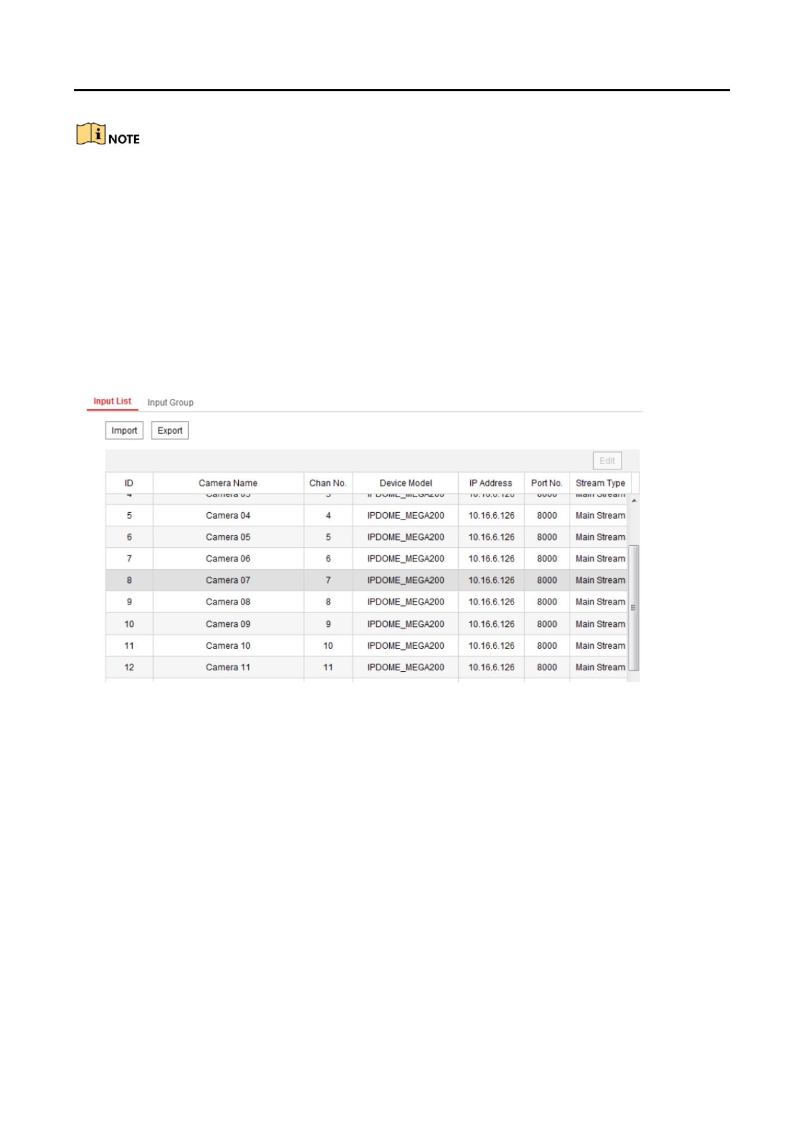
Step 1 Enter the Device Management > Input Channel > Input List page.
Figure 3-4 Import & Export of Input List
Step 2 (oponal) You can select an input channel from the list and click to edit the parameters Edit
including the input channel ID, camera name and stream type.
Step 3 Click the buon to export the input channel list (in excel) to the local directory. Export
Click the buon to import the input channel list (in excel) from the local directory. Import
Managing Input Channel Group
Step 1 Enter the Device Management > Input Channel> Input Group page.
Step 2 Click to enter the Add Input Group page. Add Group
Step 3 Edit the group name, set the auto-switch interval ( -10000 sec) and select the input 10
channels from the list to the group.

DS-1200KI/1006KI Keyboard User Manual
DS- 690 0UDI Deco der User Man ual
13
Up to 16 input groups can be added.
Figure 3-5
Manage Input Group
Step 4 You can modify the group informaon or delete the group by and Modify Group Delete
Group access.
Managing Output Channel
Step 1 Enter the Device Management > Output Channel page.
Step 2 You can check the output channel informaon, or select an output channel from the list and
edit the channel ID.
User and User-related Device Management 3.3
The default user account of the device is (administrator , and the password is set when you admin )
start the device for the rst me. The user account has the permission to add and delete admin
operator accounts and congure user parameters, and add the related devices for the added users.
You can congure 1 administrator and 15 operator accounts.
Step 1 On the System Management > User Management web page, click to enter the adding Add
user interface.

DS-1200KI/1006KI Keyboard User Manual
DS- 690 0UDI Deco der User Man ual
15
Keyboard Operation Chapter 4
Step 1 On the login interface, enter the user name and password to log in to the device.
Figure 4-1 Menu
Step 2 Press the MODE buon on the panel to enter the operaon for dierent device.
Figure 4-2
Operaon Mode Selecon
Description of Operaon Mode
Table 4-1
SN
Operation
Mode
Description
1
Keyboard
The keyboard can be used for managing the devices
(including the IPC, IP dome, DVR/NVR, MVC, decoder, video
wall controller, etc.) for control. The keyboard can add the
devices via Web browser and assign each of them the
unique device ID, and nally manage to communicate with
and realize the video wall or PTZ control through the device
ID+ operaon. command
2
MAG by IP
The keyboard can connect with the matrix access gateway,
and realize the video wall control, PTZ control, etc.
3
DVR by IP
The keyboard can connect with the DVR/NVR and remotely
call the device menu and realize PTZ control through the
virtual panel.
4
MAG by
RS- 422
The keyboard can connect with the matrix access gateway
or MVC via RS-422 serial port, and realize the video wall
control, PTZ control, etc.
5
DVR by RS-
485
The keyboard can connect with the DVR/NVR via RS-485
serial port, and remotely call the device menu and realize
PTZ control through the virtual panel.
DS-1200KI/1006KI Keyboard User Manual
DS- 690 0UDI Deco der User Man ual
16
Step 3 Use the joysck to select an operaon mode and press buon to enter the operaon. OK
Keyboard Operation 4.1
The keyboard can be used for managing the devices (including the IPC, IP dome, DVR/NVR, MVC,
decoder, video wall controller, etc.) for control.
Video Wall Control 4.1.1
Purpose:
You can select dierent window division display modes for the selected output channel. The -
congurable mul division display modes depend on the decoders, video wall controller, or Mul- -
funcon Video Center (MVC).
The 1/ 4/6/8/9/ /25/32/36 window division display modes are congurable.2/ 12/16 -
Step 1 In the operaon mode, press the buons on the keyboard panel to Keyboard Num + DEV
select the device ID (decoder, MVC and video wall controller).
When you enter no device ID (DEV), the rst decoder (device ID: 1) is set for control by
default. And if you enter no WIN ID, the window 01 is set to play the decoded video by
default.
The ID for the device (decoder and MVC) and input channel/input channel group can be
viewed on the Device Management>Device List Device Management>Input Channel , and
respecvely via Web browser page. Please refer to Chapter 3.3.
Step 2 Press the buons to select the display window for the output channel. Num + MON
You should use the iVMS 4200 client soware to select and drag the output channel to the -
corresponding display window on the video wall. Please refer to the user manual of the decoder
or MVC for the details of video wall conguraon and operaon.
Step 3 Press the buons to set the window-division display mode for the output Num + MULT
channel.
Step 4 Press the buons to set the sub-window to play the decoded video. The selected Num + WIN
sub-window ID is shown in [ ] on the interface, e.g., [02]. ID
6
Dome by
RS- 485
The keyboard can connect with the analog dome or PTZ unit
via RS-485 serial port, and realize PTZ control.

DS-1200KI/1006KI Keyboard User Manual
DS- 690 0UDI Deco der User Man ual
17
Step 5 Press the buons to select the input channel or input channel group. Num + CAM/CAM-G
You can press the PREV/NEXT buons to switch to the previous or next camera / camera
group ID.
You can press the buons to stop decoding of the current camera, or press the 0 CAM+ 0 CAM+ -
G buons to stop cycle decoding of the camera group.
Figure 4-3
Video Wall Operaon
Step 6 Operate the PTZ control on the video wall.
Move the joysck to realize pan/lt movement in 8 direcons and zoom in/out control.
Rotate the joysck in clockwise/anti-clockwise direcons l to realize the zoom in/out to
control.
The central buon of the joystick can be used to capture picture.
You can also directly press the buons or (set to screen joinng, refer to Num + CAM Num + AUX
Chapter 4.1.4) and operate the PTZ control.
Preset/Patrol/Pattern Calling 4.1.2
The keyboard can be used to control the PTZ funcon of the connected IP dome camera, including
the pan/lt movement, zoom/iris/focus adjustment, and preset/patrol/pattern calling.
Step 1 In the operaon mode, press the buons to select the output Keyboard Num + MON
channel ID.
Step 2 Press the buons to select the input channel for PTZ control. Num + CAM
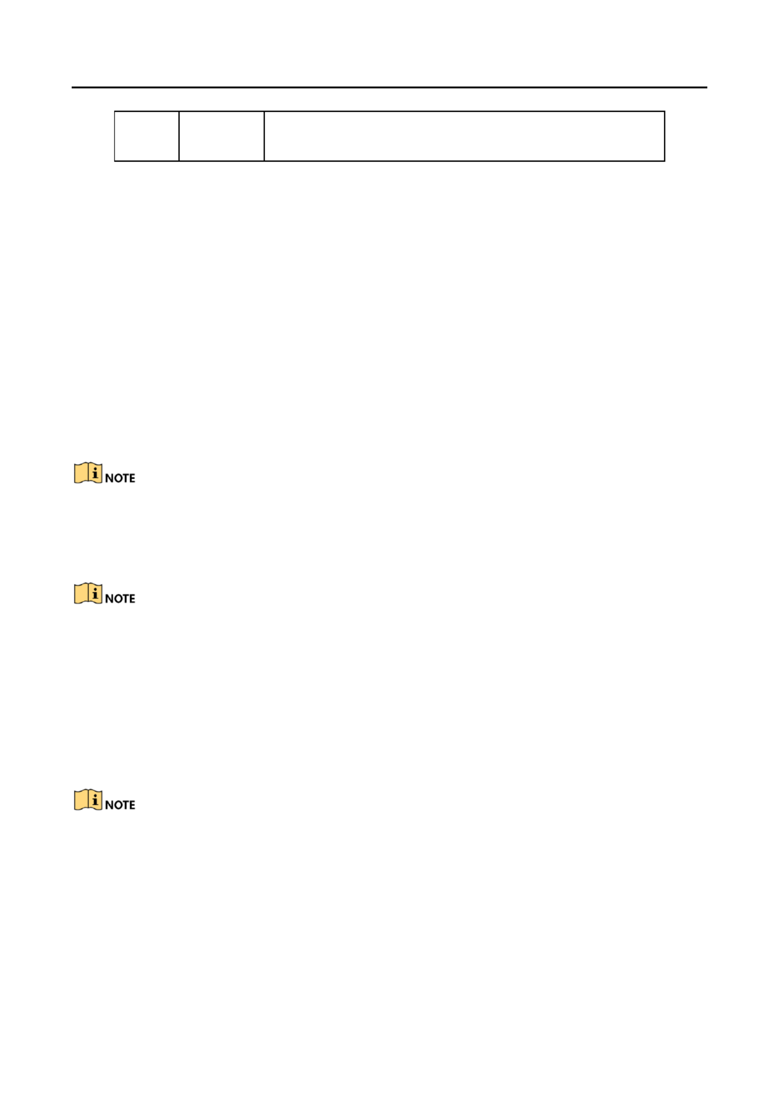
Step 3 Call the preset/patrol/paern.
P ss the buons on the keyboard panel to call the dened preset.re Num + PRESET
Press the Num + PATROL buons on the keyboard panel to call the dened patrol.
Press the Num + PATTERN buons on the keyboard panel to call the dened paern.
You can press PATTERN 0 + PATTERN directly or to call the auto scanning.
DS-1200KI/1006KI Keyboard User Manual
DS- 690 0UDI Deco der User Man ual
18
Figure 4-4 Preset Calling
The preset/patrol/paern must be pre congured. -
Scene Calling 4.1.3
Purpose:
For the MVC, video wall controller, and decoder added to the keyboard, you can congure the
scene via the iVMS 4200 client rst and follow the steps below to switch the scene.
Step 1 In the operaon mode, press the buons on the keyboard panel to Keyboard Num + DEV
select the device ID (decoder MVC and video wall controller , ).
Step 2 Press the buons on the keyboard panel to switch to the dened scene. Num + SCENE
The scene of the video wall must be pre congured for the decoder or MVC via client soware.-
Figure 4-5 Scene Calling
AUX Functions 4.1.4
The keyboard is designed with AUX/F2 key on its panel. You are allowed to congure the AUX/F2
key to picture capture or screen joinng funcons.
Screen Jointing of Video Wall
Step 1 Log in to the decoder or video wall controller via Web browser, and congure the video wall
sengs. Please refer to the user manual of decoder or video wall controller.
DS-1200KI/1006KI Keyboard User Manual
DS- 690 0UDI Deco der User Man ual
19
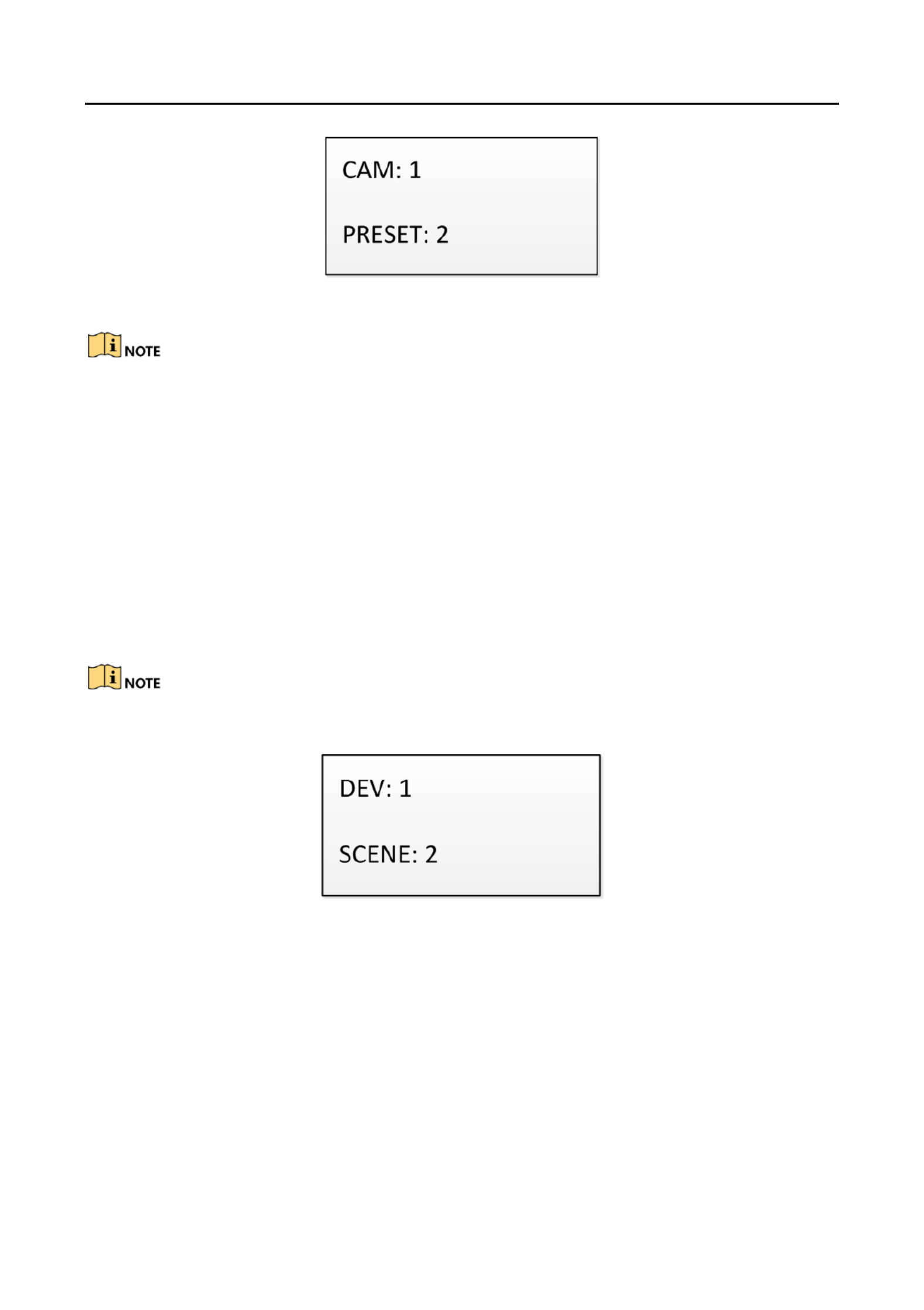
Step 2 Log in to keyboard via Web browser ( and enter the A key sengs page hps://ip address), ux
(System Management>Aux Key Sengs ).
Step 3 Set the Aux key funcon to . Screen Joinng
Step 4 Click to save the sengs. Save
Figure 4-6
Aux Key Setngs
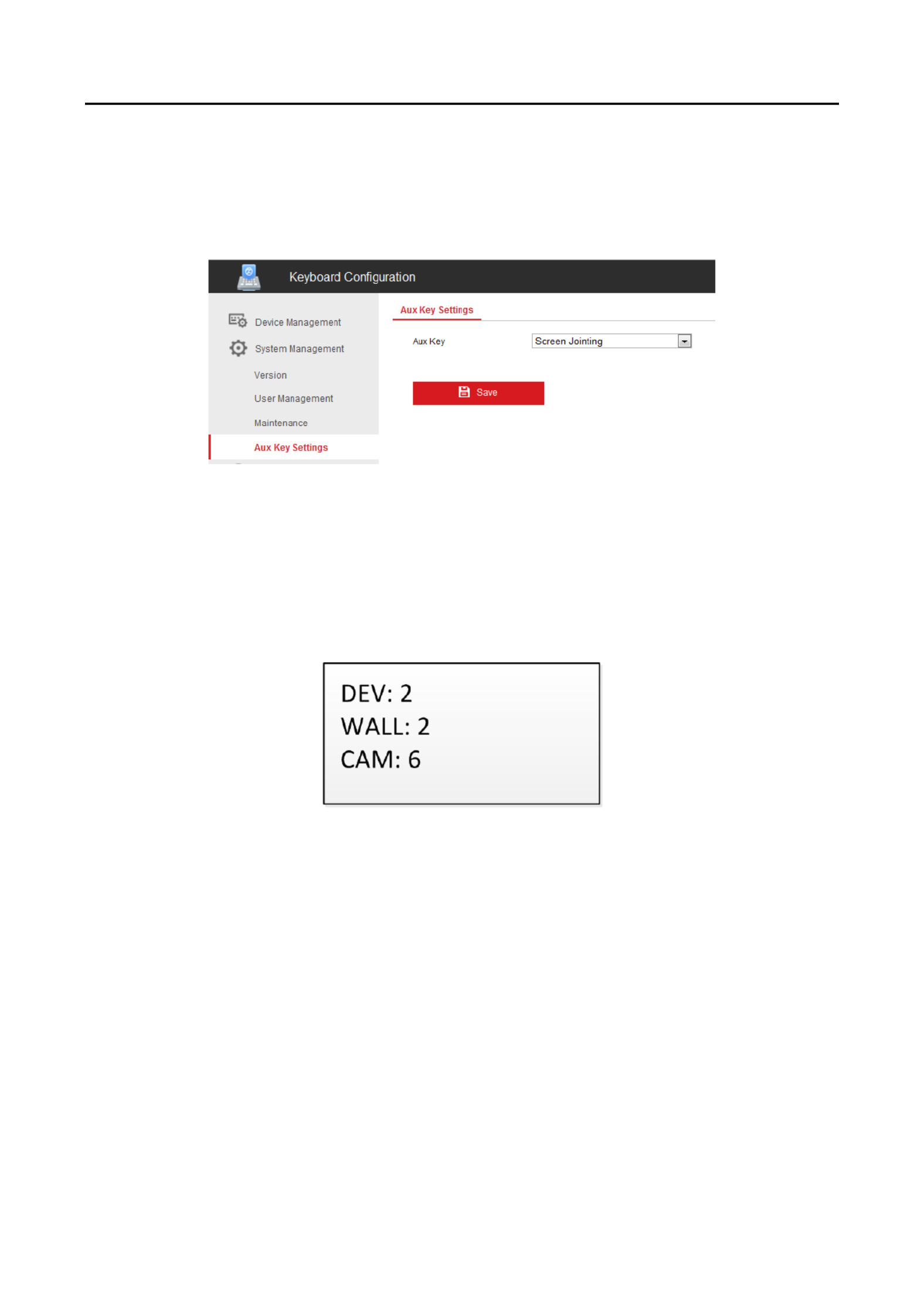
Step 5 the keyboard operaon mode, In
1) Press the buons to select the device ID Num + DEV .
2) Press the buons to operate screen joinng for the video wall. Num + AUX/F2
3) Press the buons to select the input channel. Num + CAM
Figure 4-7
Video Wall Control by AUX Key
Picture Capture
The video picture from the camera can be captured and saved in U ash disk through the keyboard -
operaon.
Step 1 Log in to keyboard via Web browser ( ), and enter the Aux key sengs page hps://ip address
(System Management>Aux Key Sengs).
Step 2 Set the Aux key funcon to Capture.
Step 3 Click to save the sengs. Save
Step 4 In the keyboard operaon mode,
1) Press the buons to select the device ID Num + DEV .

DS-1200KI/1006KI Keyboard User Manual
DS- 690 0UDI Deco der User Man ual
20
2) Press the buons to select the display window for the output channel. Num + MON
3) Press the buons to select the input channel. Num + CAM
Step 5 Press the buon on the keyboard panel to capture the picture. The picture is saved AUX/F2
in the -U ash disk in FAT32 format.
You can also use the central buon of the joysck to capture the picture in keyboard operaon
mode.
MAG by IP 4.2
The keyboard can connect with the matrix access gateway, and realize the video wall control, PTZ
control, etc.
Step 1 Log in to the keyboard via Web browser ( address), and enter the Matrix Access hps://ip
Gateway Sengs page.
Figure 4-8
Matrix Access Gateway
Step 2 Congure the parameters of the matrix access gateway. And click to save the sengs. OK
Step 3 Enter the operaon mode on the keyboard. MAG by IP
Step 4 Press the buons to select the display window for the output channel. Num + MON
Step 5 Press the buons to set the window to play the decoded video. Num + WIN
Step 6 Press the buons to select the input channel group You can press the Num + CAM .
PREV/NEXT buons to switch to the previous or next camera ID.

DS-1200KI/1006KI Keyboard User Manual
DS- 690 0UDI Deco der User Man ual
21
Figure 4-9 MAG by IP
For the inial use of MAG/MVC, you must use the conguraon kits soware to congure the
input/output channel ID of the MAG/MVC. Please refer to the user manual of MVC for details. The
input/output channel ID is used for switching on the video wall or PTZ control during keyboard
operaon.
Step 7 Operate the PTZ control on the video wall. Refer to Step 6 in Chapter 4.1.1 for details.
DVR by IP 4.3
The keyboard can connect with the DVR/NVR and remotely call the device menu and realize PTZ
control through the virtual panel.
Step 1 Log in to the keyboard via Web browser ( address), and enter the DVR/NVR device hps://ip
list (Device Management>Device List>DVR/NVR).
Step 2 Click to add the DVR/NVR device. Please refer to Chapter3.2 Device Management. Add
Figure 4- 10 DVR/NVR Management
Step 3 Enter the operaon mode on the keyboard. DVR by IP
Step 4 ess the buons on the keyboard panel to select the device ID (viewed on the Pr Num + DEV
Device Management>Device List>DVR/NVR).
DS-1200KI/1006KI Keyboard User Manual
DS- 690 0UDI Deco der User Man ual
22
Figure 4- 11 DVR by IP
Step 5 Operate the buons on the keyboard panel to realize the corresponding funcons. Please
refer to Chapter 1.4 Funconal Buons to check the descripon of the DVR control buttons.
M by RS-422 4.4 AG
The keyboard can connect with the matrix access gateway or MVC via RS 422 serial port, and -
realize the video wall control, PTZ control, etc.
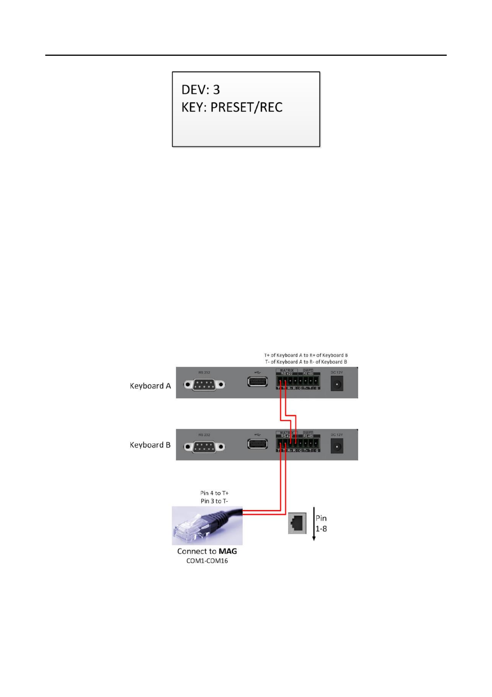
Before you start:
Check the connecon between the MAG and the Keyboard. The ad terminals of the T+ T -
keyboard’s RS 422 serial port must be connected with the and terminals of the MAG’s RS-D+ D--
422 serial port.
Refer to the following gure:
Figure 4-12
Connecon between Cascaded Keyboards and MAG
Refer to the following gure as an example for the network cable (568B). The pin 3 and pin 4 are
colored in green white and blue. -

DS-1200KI/1006KI Keyboard User Manual
DS- 690 0UDI Deco der User Man ual
23
Figure 4- 13 Network Cable
Step 1 Enter the operaon mode on the keyboard. MAG by -422RS
Step 2 Press the buons to select the display window for the output channel. Num + MON
Step 3 Press the buons to set the window to play the decoded video. Num + WIN
Step 4 Press the buons to select the input channel. Num + CAM
Figure 4-14
Matrix Operaon
Step 5 You can operate the PTZ control on the video wall for the connected dome. Refer to Chapter
4.1.2 for instrucons.
You can also press the + CAM buons to select the input channel, and operate the PTZ Num
control.
Both the MAG and MVC can be connected to the keyboard by RS 422 serial port.-
For the inial use of MAG/MVC, you must use the conguraon kits soware to congure the
input/output channel ID of the MAG/MVC. Please refer to the user manual of MVC for details.
The input/output channel ID is used for switching on the video wall or PTZ control during
keyboard operaon.
DVR by RS-485 4.5
The keyboard can connect with the DVR/NVR via RS 485 serial port, and remotely call the device -
menu and realize PTZ control through the virtual panel.

DS-1200KI/1006KI Keyboard User Manual
DS- 690 0UDI Deco der User Man ual
24
Before you start:
Check the connecon between the DVR/NVR and the Keyboard. The ad terminals of the T+ T -
keyboard’s RS 485 serial port must be connected with the and terminals of the KB port on -D+ D-
the DVR rear panel respecvely.
Figure 4- -15 RS
485 Serial Port
Step 1 Use the ClientDemo to log in to the DVR/NVR to check the remote control ID.
Step 2 Enter the operaon mode on the keyboard. DVR by RS-485
Step 3 ess the buons on the keyboard panel to select the device ID (corresponding Pr Num + DEV
to the remote ID on ClientDemo).
Figure 4-16
DVR by RS- 485
Step 4 Move the joysck and operate the buons on the keyboard panel to realize the
corresponding funcons. Please refer to to check the Chapter 1.4 Funconal Buons
descripon of the DVR control buons.
The baud rate, protocol and other parameters of RS 485 of the keyboard must be congured to -
9600, 8, 1 and none parity.
Dome by RS-485 4.6
The keyboard can connect with the analog dome or PTZ unit via RS 485 serial port, and realize PTZ -
control.
Before you start:
Check the connecon between the dome and the Keyboard. The ad terminals of the T+ T -
keyboard’s RS 485 serial port must be connected with the and terminals of the dome -T+ T-
respecvely.

DS-1200KI/1006KI Keyboard User Manual
DS- 690 0UDI Deco der User Man ual
25
Step 1 Enter the operaon mode on the keyboard. Dome by RS-485
Step 2 ess the buons to select the dome site Pr Num + CAM .
Step 3 Use the joysck and operate the buons on the keyboard panel to realize the corresponding
funcons. Please refer to to check the descripon of the PTZ Chapter 1.4 Funconal Buons
control buons.
Figure 4- -17 DVR by RS 485
The address, baud rate, protocol and other parameters of RS 485 must be congured the same -
with the dome’s RS 485 parameters.-
Shortcut Operation 4.7
The device control via keyboard can be realized by shortcut operaon.
Step 1 On the login interface, enter the user name and password to log in to the device.
Figure 4- 18 Menu
Step 2 Use the joysck to select the to enter the shortcut operaon mode. Shortcut
Step 3 Press the on Num+DEV/MON/CAM/CAM-G/PRESET/PATROL/PATTERN/WIN/MULT/SCENE
the keyboard buons to realize the corresponding device operaon and control.

DS-1200KI/1006KI Keyboard User Manual
DS- 690 0UDI Deco der User Man ual
26
System Menu Configuration Chapter 5
On the main menu aer login, you can select System to check the version, and congure the
system conguraon, including network, user, RS 485, RS 422, hardware, me and maintenance. - -
Figure 5-1 Main Menu
Refer to Chapter 3.1 Network Setngs for the conguraon of network parameters.
Version 5.2
Select Version to check the version informaon of the keyboard, including the rmware, panel,
hardware and soware version.
User Management 5.3
Select to enter the user management interface. You can change the password (admin), add User
new user, edit user or delete the user.
Click buon or the central buon of joysck to save the sengs.OK
Figure 5-2 User Management
Only the admin user is allowed to add/edit/user the user (operator).

DS-1200KI/1006KI Keyboard User Manual
DS- 690 0UDI Deco der User Man ual
27
RS-485/RS-422 Settings 5.4
You can connect the analog dome or DVR with the keyboard via RS 484 serial port, and the -
MVC/MAG with keyboard via RS 422 serial port. -
Select to enter the RS /RSRS- -485/RS 422 -485 -422 setngs interface. You can congure the address
bit (RS 485 only), baud rate, data bit, protocol (PROT: PELCO P, PELCO D, VICON, KALATEL, - - -
HIKVISION selectable), stop bit, parity, and copy all sengs. When you set the Copy All to Yes for
RS-485 serial port, the current sengs will be copied to the connecon of all other RS 485 devices.-
Click buon or the central buon of joysck to save the sengs.OK
Figure 5-3 -RS
485 Sengs
The 485/RSRS- -422 parameters congured here must be the same with the connected dome/DVR
or MVC/MAG.
Hardware 5.5
You can set the auto logo feature of the keyboard.-
Select Hardware to enter the following interface, and move (le/right) the joysck to set the A-
Logo to ON or OFF. Click buon or the central buon of joysck to save the settings.OK
When the auto logo is set to ON, the system will automacally log o aer the device is not -
operated for 30 minutes.
Figure 5-4 -Auto
Logo Sengs
DS-1200KI/1006KI Keyboard User Manual
DS- 690 0UDI Deco der User Man ual
28
Time Settings 5.6
Select to enter the system me sengs interface. You can set the value of year, month, date, Time
me format, hour, minute and second. Click buon or the central buon of joysck to save the OK
sengs.
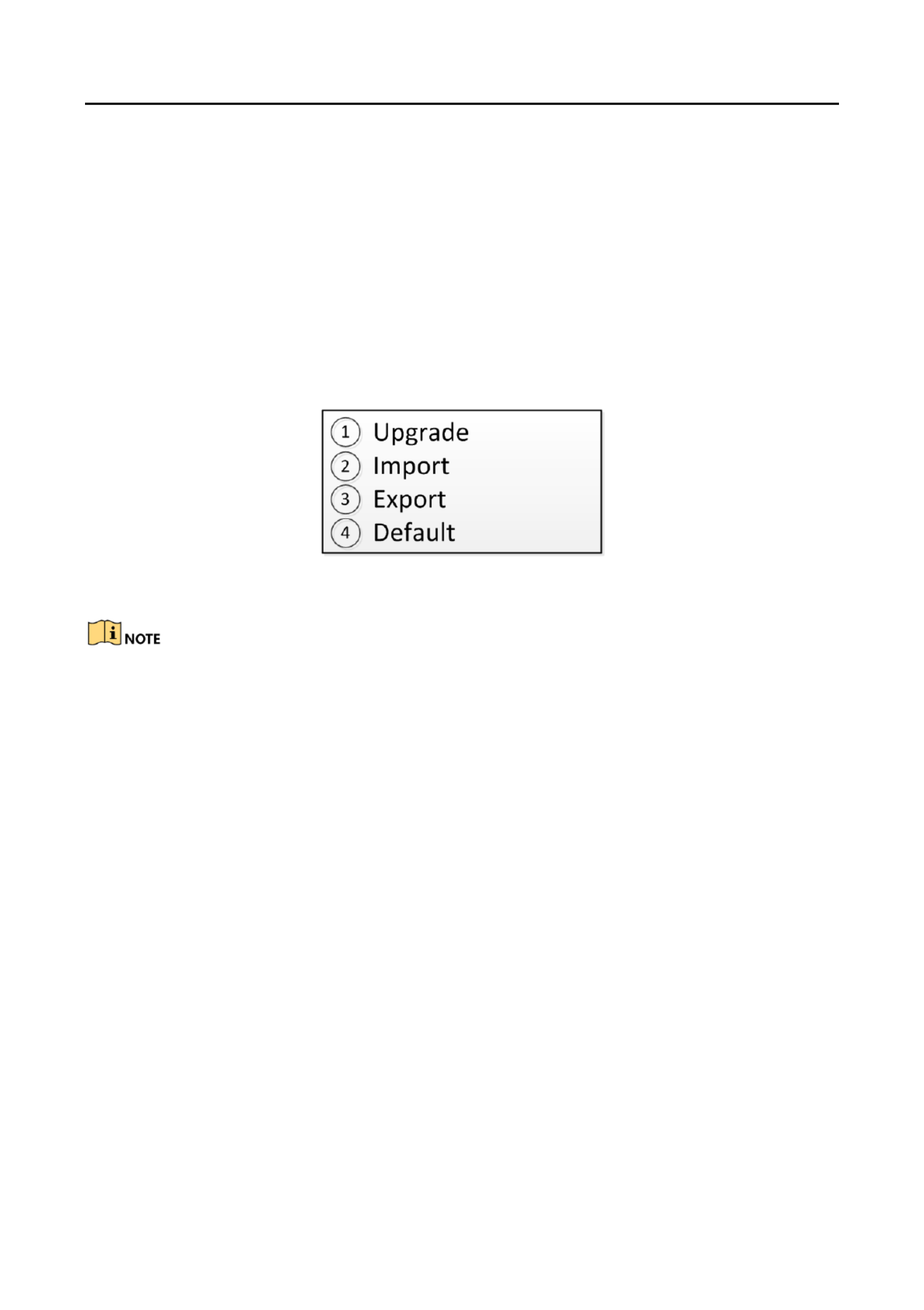
Maintenance 5.7
Select Maintenance to enter the system maintenance sengs interface. You can upgrade the
device, import and export the conguraon les, and recover the device to the factory default
sengs.
Figure 5-5 Maintenance
You should connect the U ash disk to the keyboard before upgrading, and imporng/exporng -
the les.
The upgrade le and conguraon le must be located in the root directory of the U ash disk.-
The upgrade le must be in digicap.dav; and the conguraon le in .kbCfg.bin

DS-1200KI/1006KI Keyboard User Manual
DS- 690 0UDI Deco der User Man ual
29
Specifications Chapter 6
Specication of DS
-1200KI Table 6-1
Model
DS-1200KI
System
LCD screen
128 64 x pixel screen
Joysck
4-axis joysck
Control mode
Network, RS-232, -422, RS-485 RS
External
Interfaces
Network interface
1; 10 M/100 Mbps self-adapve Ethernet
interface
Serial interface
1 RS-232, 1 RS-422, 1 RS- 485
USB interface
1 × USB 2.0
General
Power supply
12 VDC
Consumpon
≤ 4.5 W
Working temperature
-10 to +55° C (14 to 131° F)
Working humidity
10% to 90%
Dimensions (W × D × H)
435 4. 193 110 mm (17.1 × 7.6 × × × 3 inch)
Weight
≤ 1 kg (2.2 lb)
Specication of DS
-1006KI Table 6-2
Model
DS-1006KI
System
LCD screen
128 64 x pixel screen
Joysck
4-axis joysck
Control mode
RS-232, RS-422, RS-485
External
Interfaces
Serial interface
1 RS-232, 1 RS-422, 1 RS- 485
USB interface
1 × USB 2.0
General
Power supply
12 VDC
Consumpon
≤ 4.5 W
Working temperature
-10 to +55° C (14 to 131° F)
Working humidity
10% to 90%
Dimensions (W × D × H)
435 4. 193 110 mm (17.1 × 7.6 × × × 3 inch)
Weight
≤ 1 kg (2.2 lb)

DS-1200KI/1006KI Keyboard User Manual
DS- 690 0UDI Deco der User Man ual
30
Produkt Specifikationer
| Mærke: | Hikvision |
| Kategori: | Tastatur |
| Model: | DS-1006KI |
| Bredde: | 435 mm |
| Dybde: | 193 mm |
| Højde: | 110 mm |
| Vægt: | 1000 g |
| Antal pr. pakke: | 1 stk |
| Produktfarve: | Sort |
| Indbygget skærm: | Ja |
| Skærmtype: | LCD |
| Produkttype: | Kontrolpanel |
| Relativ luftfugtighed ved drift (H-H): | 10 - 90 % |
| Driftstemperatur (T-T): | -10 - 55 °C |
| Husmateriale: | Plast |
| Anbefalet brug: | Kontor |
| Forbindelsesteknologi: | Ledningsført |
| Strømkilde type: | DC |
| Enhedsgrænseflade: | RS-232 + RS-422 + RS-485 |
| Indgangsspænding: | 12 V |
| Pegeredskab: | Ingen |
| Formål: | Universel |
| Grænseflade: | Ledningsført |
| Driftsspænding: | 12 V |
| Baggrundslys: | Ingen |
| Tastatur formfaktor: | Mini |
| Tastatur dimensioner (BxDxH): | 435 x 193 x 110 mm |
| Tastatur vægt: | 1000 g |
| Tastatur stil: | Kurvet |
| Mus inkluderet: | Ingen |
| Fingeraftrykslæser: | Ingen |
| USB stik: | Ja |
| Velegnet til smartphone: | Ingen |
| Joystick: | Ja |
Har du brug for hjælp?
Hvis du har brug for hjælp til Hikvision DS-1006KI stil et spørgsmål nedenfor, og andre brugere vil svare dig
Tastatur Hikvision Manualer

2 August 2024
28 Juli 2024
18 December 2023
2 November 2022
26 Oktober 2022
Tastatur Manualer
- Tastatur SilverCrest
- Tastatur Acer
- Tastatur Denver
- Tastatur Panasonic
- Tastatur Moog
- Tastatur Philips
- Tastatur Apple
- Tastatur Logitech
- Tastatur Behringer
- Tastatur Sandberg
- Tastatur HP
- Tastatur AOC
- Tastatur Roland
- Tastatur Asus
- Tastatur Gigabyte
- Tastatur Livoo
- Tastatur Pyle
- Tastatur Tracer
- Tastatur Lenovo
- Tastatur Yamaha
- Tastatur Startone
- Tastatur Nedis
- Tastatur Logik
- Tastatur Abus
- Tastatur Adj
- Tastatur Hama
- Tastatur Belkin
- Tastatur Casio
- Tastatur Black Box
- Tastatur AKAI
- Tastatur Clas Ohlson
- Tastatur RCF
- Tastatur Trevi
- Tastatur Trust
- Tastatur JVC
- Tastatur Sandstrøm
- Tastatur Buffalo
- Tastatur Razer
- Tastatur Medion
- Tastatur Sweex
- Tastatur Vivanco
- Tastatur König
- Tastatur TechniSat
- Tastatur Gembird
- Tastatur Targus
- Tastatur Deltaco
- Tastatur BlueBuilt
- Tastatur Tripp Lite
- Tastatur Cherry
- Tastatur Exibel
- Tastatur Mad Catz
- Tastatur Microsoft
- Tastatur Penclic
- Tastatur Rapoo
- Tastatur Fellowes
- Tastatur Anker
- Tastatur Enermax
- Tastatur Technics
- Tastatur Digitus
- Tastatur Sigma
- Tastatur Zebra
- Tastatur SteelSeries
- Tastatur Cougar
- Tastatur Genesis
- Tastatur Niceboy
- Tastatur Techly
- Tastatur Dell
- Tastatur Fujitsu
- Tastatur Primus
- Tastatur Marmitek
- Tastatur Maxxter
- Tastatur NGS
- Tastatur Roccat
- Tastatur Cooler Master
- Tastatur Zalman
- Tastatur MSI
- Tastatur TERRIS
- Tastatur MT Logic
- Tastatur Corsair
- Tastatur Energy Sistem
- Tastatur Zoom
- Tastatur Korg
- Tastatur Arturia
- Tastatur TrekStor
- Tastatur Sven
- Tastatur Ducky
- Tastatur NZXT
- Tastatur Dreadbox
- Tastatur Thermaltake
- Tastatur Veho
- Tastatur Samson
- Tastatur Studiologic
- Tastatur Keith MCmillen
- Tastatur 4ms
- Tastatur Elgato
- Tastatur Alesis
- Tastatur Renkforce
- Tastatur Azio
- Tastatur Brookstone
- Tastatur Manhattan
- Tastatur SPC
- Tastatur Native Instruments
- Tastatur A4Tech
- Tastatur LogiLink
- Tastatur IK Multimedia
- Tastatur Saitek
- Tastatur RGV
- Tastatur Viper
- Tastatur Eminent
- Tastatur Connect IT
- Tastatur Hanwha
- Tastatur ILive
- Tastatur ELive
- Tastatur Tiptop Audio
- Tastatur Thomann
- Tastatur Brydge
- Tastatur X9 Performance
- Tastatur Evolveo
- Tastatur BT
- Tastatur Genius
- Tastatur Watson
- Tastatur Zagg
- Tastatur BakkerElkhuizen
- Tastatur Ozone
- Tastatur M-Audio
- Tastatur Mitel
- Tastatur V7
- Tastatur DREVO
- Tastatur Fender
- Tastatur Vorago
- Tastatur Krom
- Tastatur Contour Design
- Tastatur Voxicon
- Tastatur Iogear
- Tastatur Vimar
- Tastatur Perixx
- Tastatur Aluratek
- Tastatur GPX
- Tastatur Dahua Technology
- Tastatur Speed-Link
- Tastatur Sharkoon
- Tastatur Scosche
- Tastatur Joy-It
- Tastatur Keychron
- Tastatur Boss
- Tastatur Conceptronic
- Tastatur InLine
- Tastatur KeySonic
- Tastatur Lindy
- Tastatur GoGen
- Tastatur Kogan
- Tastatur Hammond
- Tastatur Gravity
- Tastatur ADATA
- Tastatur Kurzweil
- Tastatur Natec
- Tastatur Millenium
- Tastatur AMX
- Tastatur Homematic IP
- Tastatur Satechi
- Tastatur HyperX
- Tastatur CME
- Tastatur Kingston
- Tastatur CTA Digital
- Tastatur Geovision
- Tastatur Steren
- Tastatur Accuratus
- Tastatur Savio
- Tastatur Nord
- Tastatur IQUNIX
- Tastatur Arctic Cooling
- Tastatur Gamdias
- Tastatur Ketron
- Tastatur Media-Tech
- Tastatur Intellijel
- Tastatur K&M
- Tastatur Erica Synths
- Tastatur Goodis
- Tastatur Mad Dog
- Tastatur Nektar
- Tastatur Alienware
- Tastatur The Box
- Tastatur BeeWi
- Tastatur Kensington
- Tastatur Brigmton
- Tastatur Ednet
- Tastatur Nacon
- Tastatur Evga
- Tastatur Mede8er
- Tastatur Vakoss
- Tastatur Essentiel B
- Tastatur Ewent
- Tastatur Msonic
- Tastatur XPG
- Tastatur ENDORFY
- Tastatur Adesso
- Tastatur Satel
- Tastatur Man & Machine
- Tastatur Ergoline
- Tastatur Hawking Technologies
- Tastatur Iluv
- Tastatur Avanca
- Tastatur Mediacom
- Tastatur Havis
- Tastatur Hori
- Tastatur Woxter
- Tastatur Ibm
- Tastatur General Music
- Tastatur Gamesir
- Tastatur Matias
- Tastatur Verbatim
- Tastatur SIIG
- Tastatur Carlsbro
- Tastatur Micro Innovations
- Tastatur NPLAY
- Tastatur STANDIVARIUS
- Tastatur UNYKAch
- Tastatur Hohner
- Tastatur Pelco
- Tastatur Approx
- Tastatur Bluestork
- Tastatur Medeli
- Tastatur Goldtouch
- Tastatur Merkloos
- Tastatur Kawai
- Tastatur Xtech
- Tastatur IOPLEE
- Tastatur Native
- Tastatur I-onik
- Tastatur Laney
- Tastatur MaxMusic
- Tastatur Inovalley
- Tastatur Bontempi
- Tastatur Logic3
- Tastatur Bakker Elkhuizen
- Tastatur Venom
- Tastatur Novation
- Tastatur IPort
- Tastatur R-Go Tools
- Tastatur ModeCom
- Tastatur SureFire
- Tastatur Schubert
- Tastatur Nord Electro
- Tastatur Icon
- Tastatur X-keys
- Tastatur Stagg
- Tastatur PIXMY
- Tastatur Promate
- Tastatur ISY
- Tastatur ThunderX3
- Tastatur FURY
- Tastatur Perfect Choice
- Tastatur ASM
- Tastatur Elektron
- Tastatur Soundsation
- Tastatur NUX
- Tastatur Canyon
- Tastatur Dexibell
- Tastatur Eclipse
- Tastatur UGo
- Tastatur Krux
- Tastatur ActiveJet
- Tastatur Alogic
- Tastatur Genovation
- Tastatur Rii
- Tastatur The T.amp
- Tastatur Sequenz
- Tastatur Redragon
- Tastatur Hamlet
- Tastatur SilentiumPC
- Tastatur Leotec
- Tastatur Nuki
- Tastatur Mars Gaming
- Tastatur Roline
- Tastatur Acme Made
- Tastatur Vultech
- Tastatur TEKLIO
- Tastatur Raspberry Pi
- Tastatur Kinesis
- Tastatur Urban Factory
- Tastatur Roadworx
- Tastatur KeepOut
- Tastatur Logickeyboard
- Tastatur Gamber-Johnson
- Tastatur Seal Shield
- Tastatur Kanex
- Tastatur GETT
- Tastatur Unitech
- Tastatur Akko
- Tastatur Mountain
- Tastatur Groove Synthesis
- Tastatur CoolerMaster
- Tastatur 3Dconnexion
- Tastatur Royal Kludge
- Tastatur Universal Remote Control
- Tastatur Montech
- Tastatur ID-Tech
- Tastatur CM Storm
- Tastatur Patriot
- Tastatur Xtrfy
- Tastatur Polyend
- Tastatur Blue Element
- Tastatur CSL
- Tastatur On-Stage
- Tastatur Xcellon
- Tastatur SMK-Link
- Tastatur Loupedeck
- Tastatur DNA
- Tastatur MK
- Tastatur Getttech
- Tastatur IBox
- Tastatur Nanoxia
Nyeste Tastatur Manualer

8 April 2025
8 April 2025
4 April 2025
4 April 2025
4 April 2025
29 Marts 2025
28 Marts 2025
28 Marts 2025
27 Marts 2025
25 Marts 2025