Hikvision DS-A72072R Manual
Læs nedenfor 📖 manual på dansk for Hikvision DS-A72072R (94 sider) i kategorien Server. Denne guide var nyttig for 11 personer og blev bedømt med 4.5 stjerner i gennemsnit af 2 brugere
Side 1/94

Storage System
User Manual
UD05216B

Storage System User Manual
1
User Manual
COPYRIGHT © 6 Hangzhou Hikvision Digital Technology Co., Ltd. 201
ALL RIGHTS RESERVED.
Any and all informaon, including, among others, wordings, pictures, graphs are the properes of Hangzhou
Hikvision Digital Technology Co., Ltd. or its subsidiaries (hereinaer referred to be This user manual “Hikvision”).
(hereinaer referred to be the Manual cannot be reproduced, changed, translated, or distributed, parally or “ ”)
wholly, by any means, without the prior wrien permission of Hikvision. Unless otherwise spulated, Hikvision
does not make any warranes, guarantees or representaons, express or implied, regarding to the Manual.
About this Manual
This Manual is applicable to Storage System.
The Manual includ instrucons for using and managing the product. Pictures, charts, images and all other es
informaon hereinaer are for descripon and explanaon only. The informaon contained in the Manual is
subject to change, without noce, due to rmware updates or other reasons. Please nd the latest version in the
company website ( ). hp://overseas.hikvision.com/en/
Please use this user manual under the guidance of professional s.
Trademarks Acknowledgement
and other Hikvision’s trademarks and logos are the properes of Hikvision in various jurisdicons.
Other trademarks and logos menoned below are the properes of their respecve owners.
Legal Disclaimer
TO THE MAXIMUM EXTENT PERMITTED BY APPLICABLE LAW, THE PRODUCT DESCRIBED, WITH ITS HARDWARE,
SOFTWARE AND FIRMWARE, IS PROVIDED AS IS , WITH ALL FAULTS AND ERRORS, AND HIKVISION MAKES NO “ ”
WARRANTIES, EXPRESS OR IMPLIED, INCLUDING WITHOUT LIMITATION, MERCHANTABILITY, SATISFACTORY
QUALITY, FITNESS FOR A PARTICULAR PURPOSE, AND NON-INFRINGEMENT OF THIRD PARTY. IN NO EVENT WILL
HIKVISION, ITS DIRECTORS, OFFICERS, EMPLOYEES, OR AGENTS BE LIABLE TO YOU FOR ANY SPECIAL,
CONSEQUENTIAL, INCIDENTAL, OR INDIRECT DAMAGES INCLUDING, AMONG OTHERS, DAMAGES FOR LOSS OF ,
BUSINESS PROFITS, BUSINESS INTERRUPTION, OR LOSS OF DATA OR DOCUMENTATION, IN CONNECTION WITH
THE USE OF THIS PRODUCT, EVEN IF HIKVISION HAS BEEN ADVISED OF THE POSSIBILITY OF SUCH DAMAGES.
REGARDING TO THE PRODUCT WITH INTERNET ACCESS, THE USE OF PRODUCT SHALL BE WHOLLY AT YOUR OWN
RISKS. HIKVISION SHALL NOT TAKE ANY RESPONSIBILITES FOR ABNORMAL OPERATION, PRIVACY LEAKAGE OR
OTHER DAMAGES RESULTING FROM CYBER ATTACK, HACKER ATTACK, VIRUS INSPECTION, OR OTHER INTERNET
SECURITY RISKS; HOWEVER, HIKVISION WILL PROVIDE TIMELY TECHNICAL SUPPORT IF REQUIRED.
SURVEILLANCE LAWS VARY BY JURISDICTION PLEASE CHECK ALL RELEVANT LAWS IN YOUR JURISDICTION .
BEFORE USING THIS PRODUCT IN ORDER TO ENSURE THAT YOUR USE CONFORMS THE APPLICABLE LAW.
HIKVISION SHALL NOT BE LIABLE IN THE EVENT THAT THIS PRODUCT IS USED WITH ILLEGITIMATE PURPOSES.
IN THE EVENT OF ANY CONFLICTS BETWEEN THIS MANUAL AND THE APPLICABLE LAW, THE LATER PREVAILS.

Storage System User Manual
2
Regulatory Information
FCC Information
FCC compliance: This equipment has been tested and found to comply with the limits for a Class A digital device,
pursuant to part 15 of the FCC Rules. These limits are designed to provide reasonable protecon against harmful
interference when the equipment is operated in a commercial environment. This equipment generates, uses, and
can radiate radio frequency energy and, if not installed and used in accordance with the instrucon manual, may
cause harmful interference to radio communicaons. Operaon of this equipment in a residenal area is likely to
cause harmful interference in which case the user will be required to correct the interference at his own expense.
The device is advised to note that as a seller or a business user (Class A) Devices and intended for use outside the
Home area.
FCC Conditions
This device complies with part 15 of the FCC Rules. Operaon is subject to the following two condions:
1. This device may not cause harmful interference.
2. This device must accept any interference received, including interference that may cause undesired operaon.
EU Conformity Statement
This product and - if applicable - the supplied accessories too are marked with "CE" and comply
therefore with the applicable harmonized European standards listed under the EMC Direcve
2014/30/EU, the RoHS Direcve 2011/65/EU, the LVD Direcve 2014/35/EU.
2012/19/EU (WEEE direcve): Products marked with this symbol cannot be disposed of as unsorted
municipal waste in the European Union. For proper recycling, return this product to your local
supplier upon the purchase of equivalent new equipment, or dispose of it at designated collecon
points. For more informaon see: www.recyclethis.info
2006/66/EC (baery direcve): This product contains a baery that cannot be disposed of as
unsorted municipal waste in the European Union. See the product documentaon for specic
battery informaon. The baery is marked with this symbol, which may include leering to indicate
cadmium (Cd), lead (Pb), or mercury (Hg). For proper recycling, return the baery to your supplier or to a
designated collecon point. For more informaon see: www.recyclethis.info
Industry Canada ICES-003 Compliance
This device meets the CAN ICES-3 (A)/NMB- A) standards requirements. 3(

Storage System User Manual
3
Safety Instruction
These instructions are intended to ensure that user can use the product correctly to avoid danger or property
loss.
The precaution measure is divided into “Warnings” and “Cautions”
Warnings: Serious injury or death may occur if any of the warnings are neglected.
Cautions: Injury or equipment damage may occur if any of the cautions are neglected.
Warnings
● Proper configuration of all passwords and other security settings is the responsibility of the installer and/or
end-user.
● In the use of the product, you must be in strict compliance with the electrical safety regulations of the nation
and region. Please refer to technical specifications for detailed information.
● Input voltage should meet both the SELV (Safety Extra Low Voltage) and the Limited Power Source with
100~240 VAC or 12 VDC according to the IEC60950-1 standard. Please refer to technical specifications for
detailed information.
● Do not connect several devices to one power adapter as adapter overload may cause over-heating or a fire
hazard.
● Please make sure that the plug is firmly connected to the power socket.
● If smoke, odor or noise rise from the device, turn off the power at once and unplug the power cable, and then
please contact the service center.
Warnings Follow these safeguards to
prevent serious injury or death.
Cautions Follow these precautions to
prevent potential injury or material
damage.

Storage System User Manual
4
Table of Contents
Chapter 1 Overview ......................................................................................................................... 7
Chapter 2 Getting Started ................................................................................................................ 8
2.1 HDD Installation ............................................................................................................................... 9
2.2 Accessing by Web Browser ............................................................................................................ 10
2.3 Login .............................................................................................................................................. 11
Chapter 3 Maintenance ..................................................................................................................12
3.1 System ........................................................................................................................................... 13
3.2 Performance .................................................................................................................................. 13
3.3 General .......................................................................................................................................... 15
3.3.1 Viewing Version Information ............................................................................................ 15
3.3.2 Default Settings ................................................................................................................. 16
3.3.3 Managing Maintenance Log .............................................................................................. 16
3.3.4 Modifying Password .......................................................................................................... 16
3.3.5 SNMP Configuration ......................................................................................................... 17
3.3.6 Modifying Host Name ....................................................................................................... 17
3.3.7 Viewing Service Status ...................................................................................................... 18
3.3.8 System Upgrade ................................................................................................................ 18
3.4 Graphical Display ........................................................................................................................... 19
3.4.1 Front View ........................................................................................................................ 19
3.4.2 Pie Chart ........................................................................................................................... 20
3.5 Environmental ............................................................................................................................... 20
Chapter 4 Storage Management ..................................................................................................... 22
4.1 Managing Local HDD ..................................................................................................................... 23
4.1.1 Viewing HDD Status .......................................................................................................... 23
4.1.2 Rescanning HDD ................................................................................................................ 24
4.1.3 Positioning HDD ................................................................................................................ 24
4.1.4 HDD Initialization .............................................................................................................. 25
4.1.5 HDD Detection .................................................................................................................. 25
4.2 Array .............................................................................................................................................. 26
4.2.1 Creating Array ................................................................................................................... 26
4.2.2 Array Exception ................................................................................................................. 28
4.2.3 Rebuilding Array ................................................................................................................ 28
4.2.4 Detecting Array ................................................................................................................. 29
4.2.5 Repairing Array ................................................................................................................. 29
4.2.6 Renaming Array ................................................................................................................ 29
4.2.7 Deleting Array ................................................................................................................... 30
4.2.8 Adding Hot Spare .............................................................................................................. 30
4.2.9 Deleting Hot Spare ............................................................................................................ 31
4.3 Storage Pool ................................................................................................................................... 31
4.3.1 Adding Storage Pool .......................................................................................................... 32
4.3.2 Deleting Storage Pool ........................................................................................................ 33
4.3.3 Positioning Storage Pool ................................................................................................... 33

Storage System User Manual
5
4.4 Logical Volume ............................................................................................................................... 33
4.4.1 Creating Logical Volume .................................................................................................... 34
4.4.2 Deleting Logical Volume .................................................................................................... 34
4.4.3 Renaming Logical Volume ................................................................................................. 34
4.4.4 Enlarging Logical Volume .................................................................................................. 35
4.5 Configuration ................................................................................................................................. 35
4.5.1 Synchronization Speed and Type ...................................................................................... 36
4.5.2 Flickering Time .................................................................................................................. 36
Chapter 5 SAN ................................................................................................................................ 37
5.1 iSCSI ............................................................................................................................................... 38
5.1.1 Adding CHAP User ............................................................................................................. 38
5.1.2 Modifying CHAP User ........................................................................................................ 38
5.1.3 Enabling iSCSI .................................................................................................................... 39
5.1.4 Disabling iSCSI ................................................................................................................... 40
5.1.5 Modifying iSCSI Port .......................................................................................................... 40
5.2 FC (Optional) .................................................................................................................................. 40
5.2.1 Enabling FC ....................................................................................................................... 41
5.2.2 Disabling FC ....................................................................................................................... 42
Chapter 6 HYBRID SAN .................................................................................................................... 43
6.1 One-Key Configuration .................................................................................................................. 44
6.2 HYBRID SAN Configurati on ......................................................................................................... 44
6.2.1 Starting HYBRID SAN ......................................................................................................... 45
6.2.2 Resetting HYBRID SAN ....................................................................................................... 47
6.2.3 Record Volume .................................................................................................................. 48
6.3 Backup and Restoring .................................................................................................................... 50
6.3.1 Viewing Private Volume Information ................................................................................ 50
6.3.2 Restoring ........................................................................................................................... 51
6.3.3 Backup .............................................................................................................................. 51
6.3.4 Recovering Video Data ...................................................................................................... 52
6.4 N+1 Management .......................................................................................................................... 53
6.4.1 Adding Backup HYBRID SAN .............................................................................................. 53
6.4.2 Deleting Backup HYBRID SAN ............................................................................................ 54
6.4.3 Adding Master HYBRID SAN .............................................................................................. 54
Chapter 7 HYBRID SAN Sub-System .............................................................................................. 56
7.1 Access by Web Browser ................................................................................................................. 57
7.2 Information .................................................................................................................................... 57
7.3 Encoding Device ............................................................................................................................ 58
7.3.2 Adding Encoding Device .................................................................................................... 58
7.3.3 Modifying and Deleting .................................................................................................... 59
7.3.4 Exporting and Importing Encoding Device ........................................................................ 60
7.4 Previewing and Recording ............................................................................................................. 61
7.5 Strategy and Alarm ........................................................................................................................ 62
7.5.1 Record Plan ....................................................................................................................... 62
7.5.2 Upload Strategy ................................................................................................................. 65

Storage System User Manual
6
7.5.3 Alarm ................................................................................................................................ 67
7.6 Playing and Downloading .............................................................................................................. 69
7.6.1 Searching Video ................................................................................................................ 69
7.6.2 Locking Videos .................................................................................................................. 69
7.6.3 Playing Videos ................................................................................................................... 70
7.6.4 Downloading Videos ......................................................................................................... 72
7.7 User ............................................................................................................................................... 74
7.8 System Configuration ..................................................................................................................... 74
7.8.1 System Alarm .................................................................................................................... 74
7.8.2 HYBRID SAN Version ...................................................................................................... 75
7.9 Log Management ........................................................................................................................... 76
7.9.1 Searching Log .................................................................................................................... 76
7.9.2 Exporting Log .................................................................................................................... 77
7.9.3 Clearing Log ...................................................................................................................... 77
Chapter 8 System ............................................................................................................................ 78
8.1 Network ......................................................................................................................................... 79
8.1.1 Modifying Data Network Interface ................................................................................... 79
8.1.2 Binding Network Interfaces .............................................................................................. 79
8.1.3 Adding Route .................................................................................................................... 80
8.1.4 MAC and IP Bonding ......................................................................................................... 81
8.1.5 Advanced Parameters ....................................................................................................... 81
8.2 Alarm ............................................................................................................................................. 84
8.2.1 Alarm Type ........................................................................................................................ 84
8.2.2 Adding Email ..................................................................................................................... 86
8.2.3 Testing Email ..................................................................................................................... 87
8.2.4 Adding SNMP Manager ..................................................................................................... 87
8.2.5 Testing SMTP Manager ..................................................................................................... 88
8.3 Time .............................................................................................................................................. 88
8.3.1 Adjusting System Time ...................................................................................................... 88
8.3.2 Synchronizing Time ........................................................................................................... 89
Chapter 9 Log . ................................................................................................................................ 90
9.1 Operation Log ................................................................................................................................ 91
9.2 Performance Log ............................................................................................................................ 91
9.3 Upgrade Log ................................................................................................................................... 92

Storage System User Manual
7
Chapter 1 Overview
Purpose:
DS-A80& series storage system is a high-performance and highly reliable storage system. Designed with four 81
enterprise-class gigabyte network interfaces, it provides a bandwidth with 4 to 8G bps transmission capability and
a huge storage space. It is integrated with multiple advanced technologies, including a 64-bit hexa-core processors,
stable architecture, and the RAID 6 storage technology, thus to run reliably and protect user data security
effectively.
Figure 1. 1 I Table 1. 1 GUI IntroductionGU and introduce the elements appear in the GUI (Graphical User
Interface) and clarify names for each element.
Figure 1. 1 I GU
Table 1. 1 GUI Introduction
No.
Name
Description
1
Banner and device
model
Shows the device model.
2
Running status
A shortcut for obtaining the real-time running status.
3
Navigation Bar
Lists the storage system menu.
4
Help and logout
A shortcut for accessing user manuals, downloading software, and logout.
5
Operation window
Lists the parameters. You can configure parameters in the area.

Storage System User Manual
8
Chapter 2 Getting Started
Purpose:
The chapter introduces HDD installation steps, web browser access steps, and login steps.
Table 2. 1 Module Description
Module
Description
HDD Installation
Describes the steps HDD installation. of
Web Browser Access
You can get access to the storage system via a server with the web browser
installed.
Login
Introduces login storage system steps.
Key Words:
HDD Installation, Web Browser Access, Login

Storage System User Manual
9
2.1 HDD Installation
In the event of device appearance shown in following steps conflicts with real device, the later prevails.
Before you start:
Prepare the following equipment and accessories.
A storage system
Hard HDDs
A pair of anti-static gloves
A screwdriver
Steps:
1. Press the blue button. Then the handle pops up.
Figure 2. 2 Press the Blue Button
2. Hold the hander and pull the HDD dummy out of the slot.
Figure 2. 3 Pull out the HDD Dummy
3. Use the screwdriver to uninstall the baffle in the bottom of HDD slot.
4. Place an HDD in the HDD dummy. The SATA interface must face the HDD dummy rear.

Storage System User Manual
10
Figure 2. 4 Place HDD
5. Adjust the HDD position. Ensure the HDD rear aligning with HDD dummy rear and the two screw holes
aiming at the holes that marked with red frame in Figure 2. 5 HDD Position.
Figure 2. 5 HDD Position
6. Use a screwdriver to fasten the four screws into the screw holes in both sides.
Figure 2. 6 Install Screws
7. Push the HDD dummy back into the slot.
Figure 2. 7 the HDD Dummy into Slot Push
2.2 Accessing by Web Browser
You shall acknowledge that the use of the product with Internet access might be under network security risks. For
avoidance of any network attacks and information leakage, please strengthen your own protection. If the product
does not work properly, please contact with your dealer or the nearest service center.
Purpose:
You can get access to the storage system via a server with a web browser installed, without needing to install any
other software. The recommended web browsers are Internet Explorer 8 and Internet Explorer 11.
Before you start:
Storage System User Manual
11
1. Use a network cable to connect the system Ethernet port and the storage system managemen network t
interface.
2. Configure the server IP address. Ensure it is in the same network segment with the IP address of
management network interface is 10.254.254.254.
Steps:
1. Open web browser.
2. Input the storage system IP address (https://10.254.254.254:2004) in Web er brows address bar.
3. Press . Enter
2.3 Login
Steps:
If the device has not been activated, you need to activate the device first before login.
1. Set the password for the admin user account.
2. Click to login to the device. OK
STRONG PASSWORD RECOMMENDED–We highly recommend you create a strong password of your own
choosing (Using a minimum of 8 characters, including at least three of the following categories: upper case
letters, lower case letters, numbers, and special characters.) in order to increase the security of your product.
And we recommend you reset your password regularly, especially in the high security system, resetting the
password monthly or weekly can better protect your product.
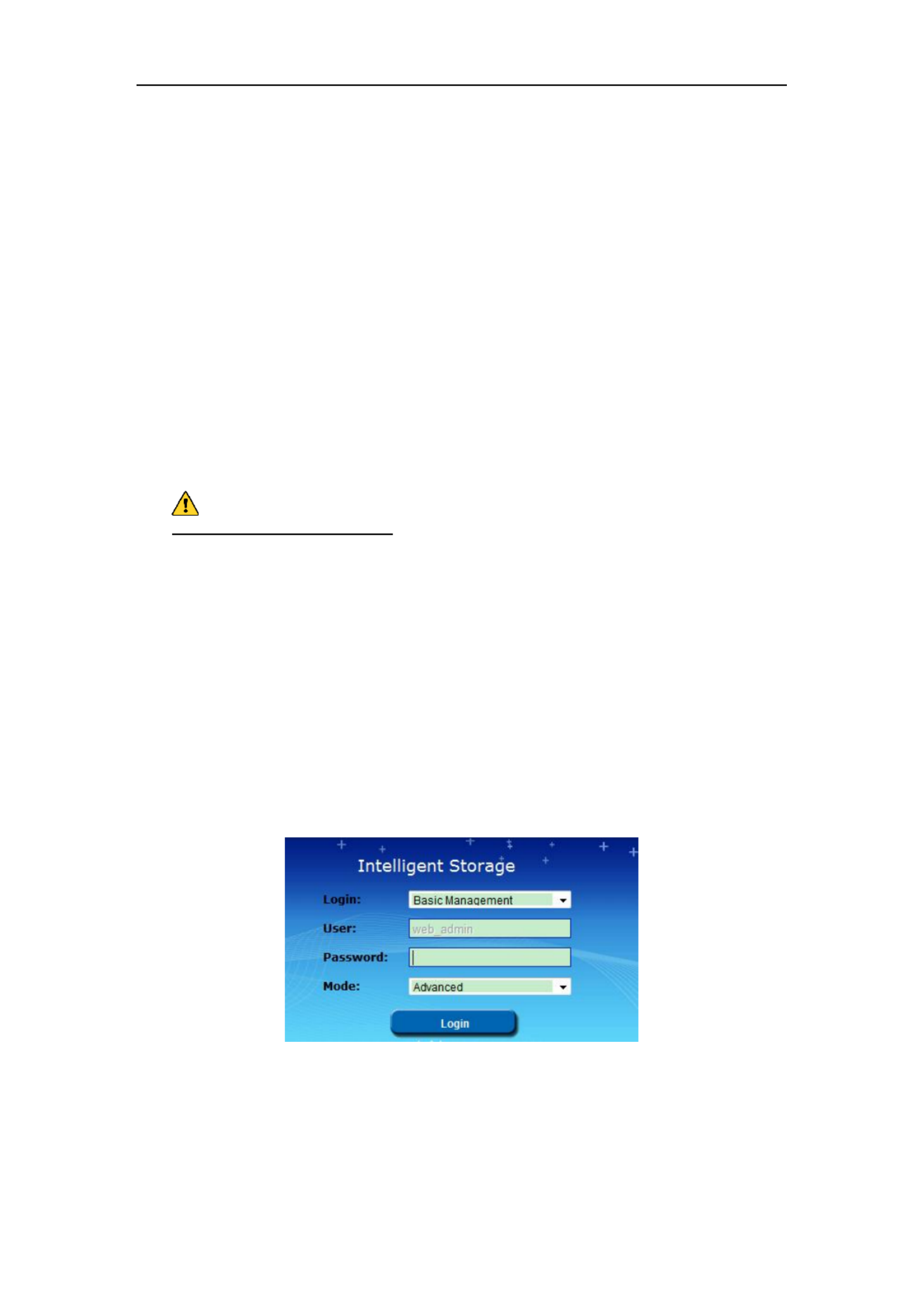
If the device is already activated:
1. Select account as Login Basic Management or HYBRID SAN Sub-system.
Basic Management: Used to configure basic parameters of the storage system.
HYBRID SAN Sub-system: Used to into the HYBRID SAN sub-system. Log
2. Select User name.
3. Enter Password.
4. Mode is Advanced by default and is not selectable.
5. Click to log in the system. Login
Figure 2. 8 Login
Storage System User Manual
12
Chapter 3 Maintenance
Purpose:
Maintenance function enables you to view login and iSCSI information, monitor running status, restore default
settings, check and download logs, upgrade storage system, and so forth.
Table 3. 1 Module Description
Module
Description
System
● A shortcut for reboot and shutdown.
● Lists the login user information and iSCSI connection information.
Performance
Shows you the real-time graph and data of system performance, including
bandwidth usage, memory usage, CPU usage, IO status, and Vmstatus.
General
You can view system version, reset system, view logs, upgrade system, and add
check and repair strategy.
Graphical Display
Provides a graph to show the front view status and a pie chart to show the storage
information.
Environmental
Shows the fan information, module temperature, fan control panel version, and
chassis power.
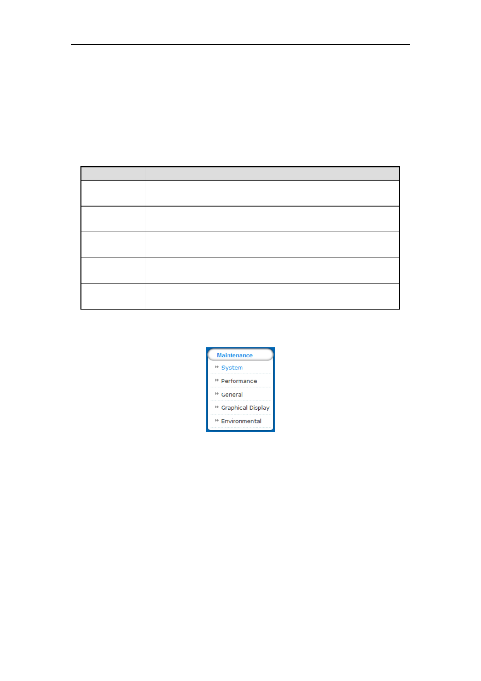
Key words:
System, Performance, General, Graphical Display, Environmental
Figure 3. 2 Maintenance
Storage System User Manual
13
3.1 System
Purpose:
Once you log into the storage system, system menu appears. System menu is a shortcut for reboot and shutdown
and lists the login users and iSCSI connection information.
Steps:
1. Click Maintenance in navigation bar and choose System to enter System interface.
Figure 3. 3 System Monitor
2. Reboot, power off, or view login information or iSCSI connection info.
Click Reboot Power off or to restart or down the storage system. shut
The logged in users and IP addresses are list in the ed Login info.
The LUN ID iSCSI ID Initiator name iSCSI connection info, , and are list in ed , which shows which
devices are connecting iSCSI .
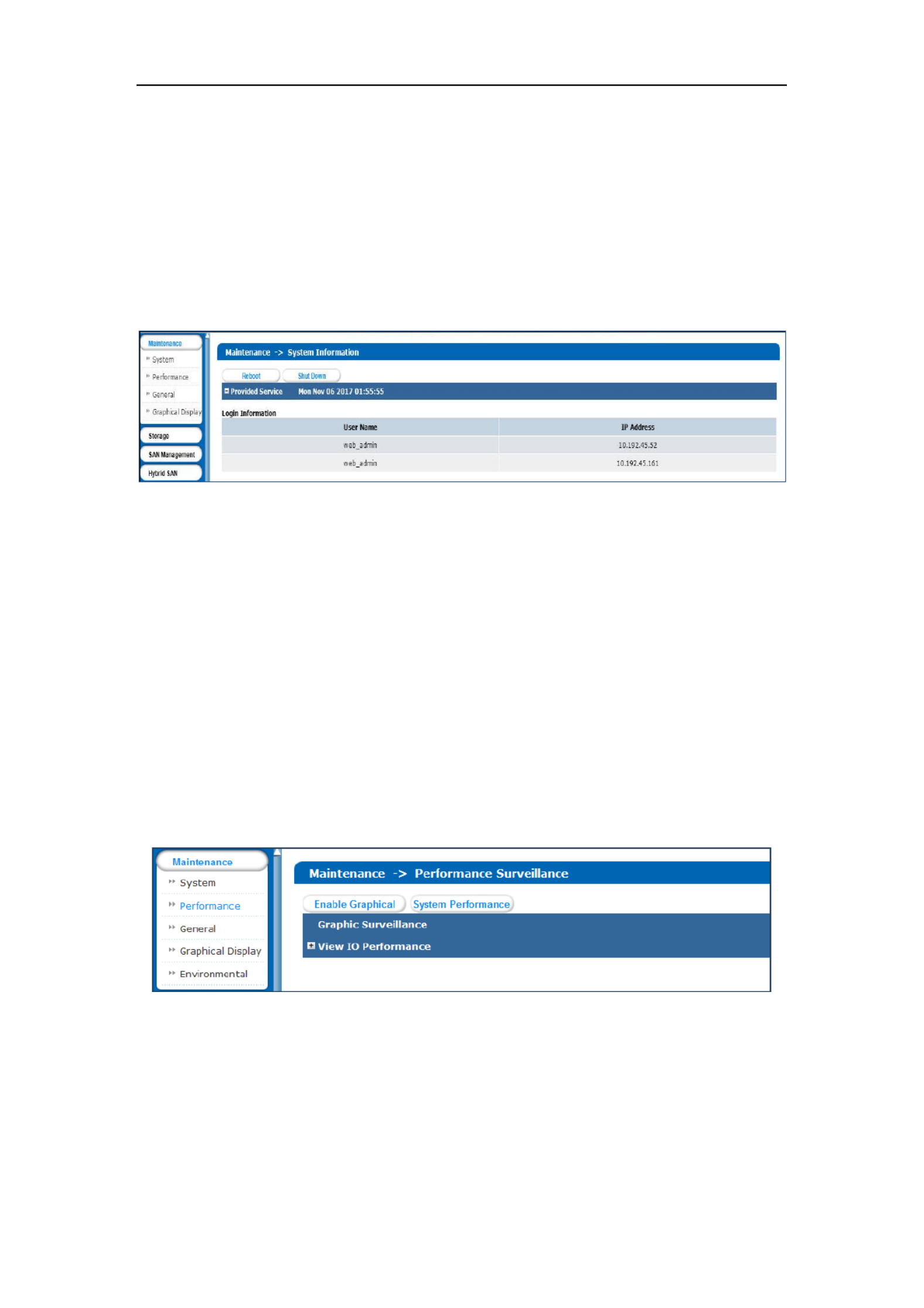
3.2 Performance
Purpose:
Performance menu shows you the real-time graph and data of system performance, including bandwidth usage,
memory usage, CPU usage, IO status, and system performance.
Steps:
1. Click Maintenance in navigation bar and choose enter Performance interface. Performance to
Figure 3. 4 Performance
2. Click Enable Graphical to show the real-time graphs of bandwidth usage, memory usage, and CPU usage.
3. Optionally, click Disable Graphical to fold the graphs.
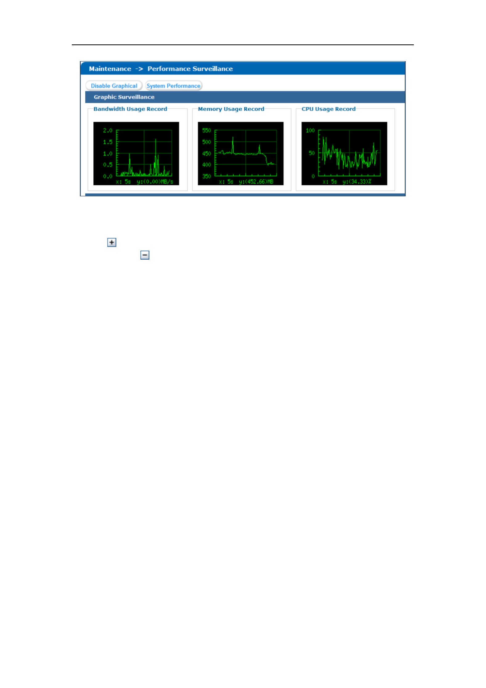
Storage System User Manual
14
Figure 3. 5 Graph Monitor
4. Click System Performance to pop up system performance window. System performance updates per
second.
5. Click of View IP Performance to unfold input/output status.
6. Optionally, click of View IP Performance to fold input/output status.

Storage System User Manual
15
3.3 General
Purpose:
You can view system version, reset system, view logs, and upgrade system.
Step:
Click Maintenance in navigation bar and choose . General
Figure 3. 6 General
3.3.1 Viewing Version Information
Purpose:
Version information interface lists information including SMI, HYBRID SAN , Support, and so on.
Steps:
1. Click Version information to pop up version information window.
2. Click to close the window. Cancel
Figure 3. 7 Version Information
Storage System User Manual
16
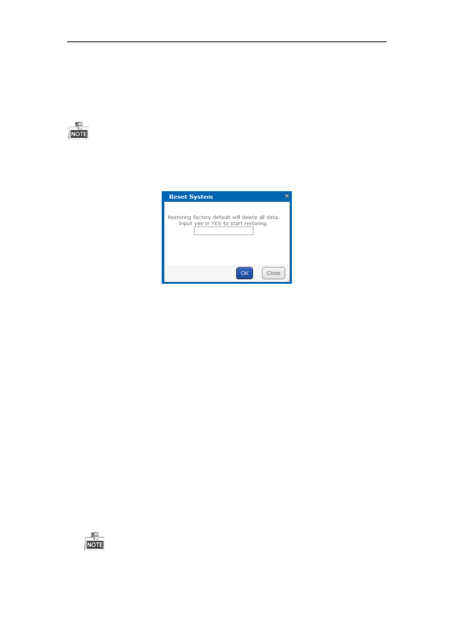
3.3.2 Default Settings
Purpose:
You can reset system to factory defaults when system is abnormal. You are recommended to reset system under
the direction of professional technical support.
Resetting operation won restore administrator user name and password, RAID configuration, hot spot ’t
configuration, and network parameters.
Steps:
1. Click Reset system to pop up reset system dialog.
Figure 3. 8 Reset System
2. Enter or in text field and click to reset. yes YES OK
3.3.3 Managing Maintenance Log
Purpose:
When system is abnormal, you can download the maintenance log to analyze problems.
Steps:
For details, refer to 9.1 Operation Log.
3.3.4 Modifying Password
Purpose:
You can modify password for basic management system and BRID SAN -system user. HY sub
Steps:
1. Click Modify password. And modify password window appears.
2. Select User Name web_admin nvr_admin as or .
web_admin: Basic management system user name.
nvr_admin: HYBRID SAN sub-system user name.
3. Enter Old Management Password and the same password in New Management Password Confirm and
Management Password.
The security level of modified password should not be lower than low security.
Password can only contain numbers, lowercase, uppercase, and underline for your password.

Storage System User Manual
17
Figure 3. 9 Modify Password
4. Click and click in popup message dialog to save the new password. OK OK
Once password is modified, it jumps to login interface. You need to enter the new password to log in.
Another controller password changes with the current controller password.
3.3.5 SNMP Configuration
Purpose:
By configuring SNMP parameters, you can log in PRTG Traffic Grapher tool to monitor the system status, including
exception information, CPU usage, and so forth.
Steps:
1. Click SNMP Configuration button.
Figure 3. 10 SNMP Configuration
2. SNMP Version V2(v2cis ) by default and is not editable.
3. Enter User Name Contact Physical address., , and
4. Click to save the settings. Then you can view system status by logging in PRTG Traffic Grapher Tool. OK
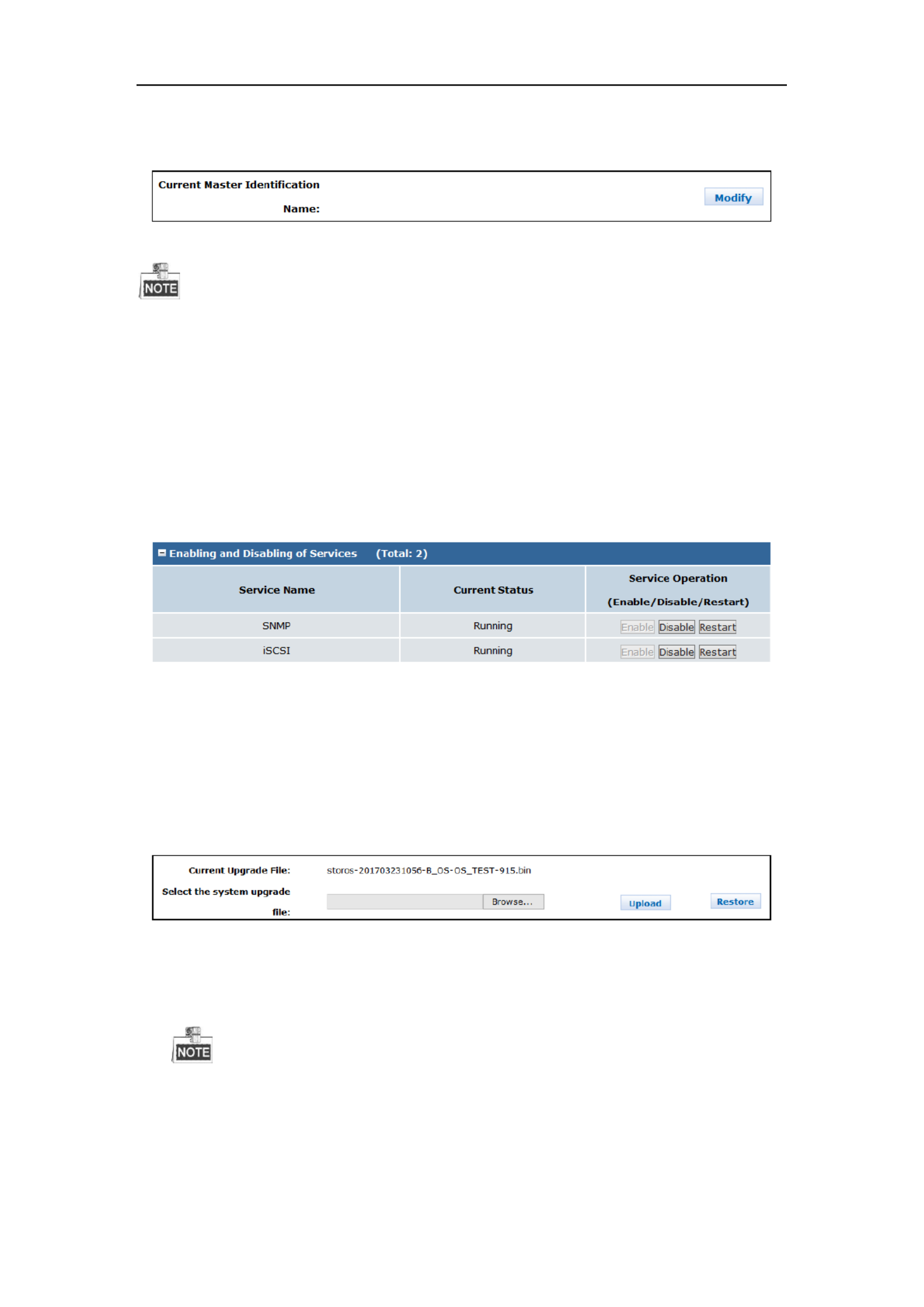
3.3.6 Modifying Host Name
Steps:
1. Click and text field appears. Modify
Storage System User Manual
18
2. Enter host name in the text field.
3. Click to activate the new host name. Modify
Figure 3. 11 Modify Host Name
Only letters (a to z and A to Z) numbers (0 to , and underline (_) can be input. , 9)
3.3.7 Viewing Service Status
Purpose:
Whether the services are running or not. You can enable, disable, or restart the services.
Steps:
Click to start the service that is not running. Enable
Click to shut down the running service. Disable
Click Restart to restart services.
Figure 3. 12 Service Status
3.3.8 System Upgrade
Purpose:
You are recommended to upgrade system under the help of professional support.
Steps:
1. Click System upgrade in Common menu to enter Application Service interface.
Figure 3. 13 Application Service
2. Click and choose the upgrade package. Browser
3. Click Upload to upgrade. After upgrade succeeded, reboot the storage system to activate the new version.
4. Optionally, you can click Restore to restore to previous version.
You can only restore to the last upgraded version.

Storage System User Manual
19
3.4 Graphical Display
Purpose:
The storage system provides graph to show the front view status and pie chart to show the storage a a
information .
Step:
Click Maintenance in navigation bar and choose Graphical Display to enter Graphical Display interface.
Figure 3. 14 Graphical Display
3.4.1 Front View
Purpose:
Front view can show you the HDD status.
Steps:
1. Click Front View in Graphical Display menu to show front view.
Table 3. 2 Indicator Status Description
Indicator
Color
Description
Top indicator
Unlit
HDD doesn t exist. ’
Green
HDD is connected and recognized.
Bottom indicator
Green
HDD is normal.
Blue
Reading and writing normally.
Red
HDD is rebuilding.
2. Positioning the pointer in a green indicator slot. Then the message dialog appears.
Figure 3. 15 HDD Information
3. Click Overview to view information of all HDD.

Storage System User Manual
20
Figure 3. 16 HDD Overview
4. Optionally, click Refresh in top-right corner to update the front view.
3.4.2 Pie Chart
Purpose:
Pie chart shows the free size of all storage modules, including system, LUN, snapshot, HYBRID SAN , iSCSI, and FC.
Steps:
1. Click in Graphical Display to enter Pie Chart interface. Pie Chart
2. Positioning the pointer in the part you want to view. and free size Free size Percentage appear in a dialog.
3. Optionally, click Refresh in top-right corner to update the information.
Figure 3. 17 Pie Chart
3.5 Environmental
Purpose:
Environmental shows the fan information, module temperature, fan control panel version, and chassis power.
Steps:
1. Click Maintenance Control Message in navigation bar and choose to enter Control Message interface. Fan
RPM (Revolutions per Minute), temperature, and other information are shown.
You can install or uninstall fans. Up to 6 fans formation can be connected. ’

Storage System User Manual
22
Chapter 4 Storage Management
Purpose:
Storage management provides configuration including HDD management, array, storage pool, LUN (logical
Volume), and storage settings.
Table 4. 1 Module Description
Module
Description
HDD Management
You can:
View HDD information and status.
Rescan, positioning, initialize, and detect HDD s.
Array
You can:
Create arrays.
Add hot spare.
View array and hot spare information.
Delete array and hot spare.
Storage pool
You can:
Add, delete, and positioning storage pools.
Remove and positioning HDDs.
View system total and free capacity.
LUN (Logical volume)
You can
Add and delete LUNs.
Rename, expand, clone, and snapshot LUNs.
Configurations
You can:
Set array synchronization speed.
Set array synchronization type.
Set flicking frequency for HDD positioning indicator.
Key words:
HDD Management, Array, Storage Pool, LUN (Logical Volume) Configuration ,
Figure 4. 2 Storage

Storage System User Manual
23
4.1 Managing Local HDD
Purpose:
You can view the HDD information here, including HDD location, supplier, model, size, status, and belonging
group.
Step:
Click Storage in navigation bar and choose . HDD Management
Figure 4. 3 HDD Management
4.1.1 Viewing HDD Status
Purpose:
You can view status of one HDD or all HDDs.
4.1.1.1 One HDD
Steps:
1. In the HDD information list, Click an HDD. HDD state dialog appears. Details of
2. Click to view the HDD SMART detection information. SMART
Figure 4. 4 HDD Status
4.1.1.2 A HDDs ll
Steps:
1. Click HDD Status in the upper left corner.
2. Click of an HDD to view its SMART detection information. SMART

Storage System User Manual
24
Figure 4. 5 HDD Status
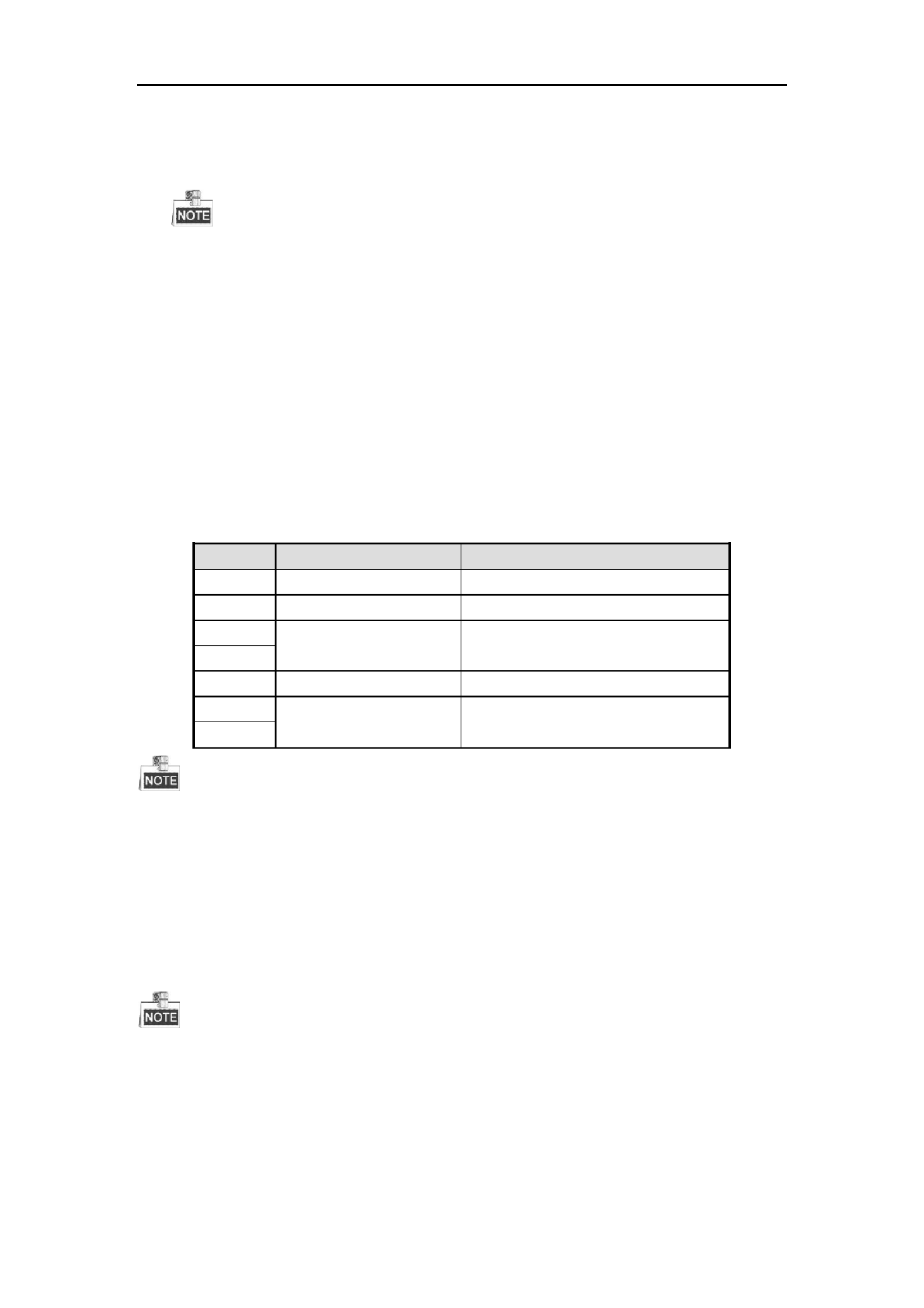
There are totally 6 kinds of status for an HDD.
Table 4. 2 HDD Status Description
Status
Description
Normal
HDD works normally.
Undetected
HDD failed the HDD detection.
Lost
HDD unrecognized is .
Risky
Exception occurs during HDD detection. But it can still work.
Bad
HDD is kicked out by an array.
Warning
HDD read and writing speed is higher than 10 MB/S during pressure test.
4.1.2 Rescanning HDD
Step:
If detecting a newly installed HDD failed, click Rescan to find the HDD.
If an HDD is uninstalled from the storage system, click to remove it from the HDD interface. Rescan
Rescanning HDDs may result in HDD status appearing as Unknown. Fresh the interface or click again to Rescan
solve the problem.
4.1.3 Positioning HDD
Purpose:
HDD bottom indicator flickers after enabling the function. It enables you to find a certain HDD more easily.
Before you start:
Set the flickering time first. For details, refer to 4.5.2 ickering TimeFl .

Storage System User Manual
25
Steps:
1. Check the checkbox of HDD you want to find.
2. Click Position and click OK in popup dialog box. Then HDD indicator keeps flickering in red for the set
flickering time.
4.1.4 HDD Initialization
Purpose:
To recover an HDD w s status uninitialized or w it is kicked out by an array, you can initialize it. hen it is hen
Steps:
1. Check the checkbox of HDD you want to initialize.
2. Click Initialize and click OK in popup dialog box to start initializing.
4.1.5 HDD Detection
Purpose:
To recognize an HDD which is added to a storage system for the first time detect , it.
Steps:
1. Check the checkboxes of HDDs to detect.
2. Click Detect.
Figure 4. 6 HDD Detection
3. Select the Detection Mode Rapid Comprehensiveas or .
Rapid: Detect parts of all HDD blocks It takes shorter time than Comprehensive. .
Comprehensive: Detect HDD blocks. It takes longer time than Rapid. all
It is recommended to operate rapid detection when system is under low pressure.
You are recommended to operate comprehensive detection for the first use HDD.
To keep data safe, detect an HDD every 3 months.
4. Click to start detecting. The selected detection mode detection progress, and detection time are listed Start ,
in the top part of the interface.

Storage System User Manual
26
5. Optionally, click Refresh to update the detection status, detection process and detection time.
Or you can click Stop to end all detections.
There are 3 kinds of detection status: Unsubmitted, Detecting, and Completed .
Table 4. 3 Detection Status Description
Check Status
Description
Uncommitted
HDD detection has no been committed. t
Detecting
HDD being detected. is
Waiting
Another HDD is being detected You need to wait till the detection is finished. .
4.2 Array
Purpose:
You can create and manage array.
Step:
Click Storage in navigation bar and choose Array.
Figure 4. 7 Array
4.2.1 Creating Array
Purpose:
You can use available HDDs to create array.
Steps:
1. Click Create Array.

Storage System User Manual
27
Figure 4. 8 Create Array
2. Input Array Name in text field.
3. Select Array Type in drop-down list. and are RAID 0, RAID 1, RAID 3, RAID 5, RAID 6, RAID 10, RAID 50
selectable.
Figure 4. 9 Required HDD Quantity
Array Type
Required HDD Quantity
RAID 0
At least 2 HDD s.
RAID 1
At least 2 HDD s.
RAID 3
At least 3 HDD s.
RAID 5
Valid range: [3, 12].
RAID 6
At least 4 HDD s.
RAID 10
RAID is made of RAID 0 and RAID 1 which require
at least 4 even HDD s.
RAID 50
RAID is made of RAID 0 and RAID 5 which require
at least 6 even HDD s.
4. Select Array Block Size(KB) in drop-down list.
5. Select as I/O Priority Performance Priority Protection Priority Balanced Smart, , , or .
Performance Priority: To guarantee external IO task performance, internal IO task is totally stopped.
Protection Priority: To guarantee internal IO task performance, external IO task would only take the
rest channel.
Balanced: When both internal and external IO task exist, Balance ensures internal IO task occupy
certain channel without influencing external IO task.
Smart: Without external IO task, array is initialized in the highest speed. array is initialized in the Or
lowest speed.
If RAID level is RAID 0, I/O priority is available. un
Storage System User Manual
28
6. Select the Available HDDs to create RAID.
Or select to create RAID. Available arrays
Or select the combination of Available HDD Available arrayss and .
Only enterprised HDD are listed in Auailable HDDs list. s
In order to increase the performance of created RAID, it is recommended to HDDs of the same use
model and capacity when creating a RAID.
7. Click to create array. The successfully created array lists in Array information list. Once created, the array OK
starts initializing.
4.2.2 Array Exception
Purpose:
If HDD failure occurs, array degrades. When more HDDs fail, array fails. Degraded array can keep working.
However, failed array cannot work. Notification area will notify you once array degraded or failed. Refer to
following table for array degraded and failed condition.
Table 4. 4 Array Degraded Condition
RAID Level
Degraded Condition
Failed Condition
RAID 0
RAID 0 will not degrade.
One HDD fails.
RAID 1
N- HDDs fail. 1
All HDDs fail.
RAID 3
One HDD fails.
Two HDDs fail.
RAID 5
RAID 6
N- HDDs fail. 1
More than three HDD fail. s
RAID 10
One HDD fails.
Two HDDs fail in either contained RAID.
RAID 50
If array in storage pool degrades, physical volume degrades.
If array in storage pool fails, physical volume fails.
4.2.3 Rebuilding Array
Purpose:
Rebuilding refers to the process of using a normal HDD or array to virtually place a failed HDD in degraded re a
array. The normal HDD can be hot spare HDD, newly inserted HDD, and so forth.
During rebuilding process, if the rebuilding HDD fails, the array stays degraded.
During rebuilding process, if a normal HDD in array fails, the array becomes failed.
During rebuilding process, if I/O error occurs to the rebuilding HDD, you need to change rebuilding HDD.
4.2.3.1 Rebuilding with Hot Spare
Before you start:

Storage System User Manual
30
4. Click to save the new name. OK
4.2.6.1 Modify I/O Priority
Steps:
1. Click Maintenance of an array in Array information list.
2. Click Modify.
3. Select in dropdown list. I/O Priority
4. Click . OK
4.2.6.2 Pause Initialization/Rebuilding/Detection/Repair
Purpose:
When the array is initializing, rebuilding, detecting, or repairing, you can pause.
Steps:
1. Click Maintenance of an array in Array information list.
2. Click to pause current process. Pause
3. You can click to resume. Keep
4.2.7 Deleting Array
Steps:
1. Check the checkbox of array you want to delete.
2. Click button to delete.
If the array has been added to a storage pool, you need to remove it from storage pool first, or it can t be deleted. ’
4.2.8 Adding Hot Spare
Purpose:
The hot spare HDD can replace failed HDD in the degraded array. In order to protect data from damage in case of
HDDs in array fail, it is recommended to add hot spare HDDs for a created array.
RAID 0 will not degrade. So you need not add local hot spare HDD for it.
Steps:
1. Click Add Hot Spare Disk to enter Add hot spare interface.
2. Select Group Global Area Local as , , or .
Global: Global hot spare H s can replace failed HDDs in any degraded arrays of storage devices in DD
the same system.
Area: Area hot spare HDDs replace failed HDDs in any degraded arrays of one storage system.
Local: Local hot spare HDDs replace failed HDDs in designated array.

Storage System User Manual
31
Priority of hot spare: Local hot spare › area hot spare › global hot spare
3. If Group is Area, select available array in Area dropdown list.
If Group is Local, select array in Array dropdown list.
4. Select at least one Available HDD.
Or select at least one Available array.
Or select the combination of Available HDD Available array or .
5. Click to create hot spare. OK
Figure 4. 10 Add Hot Spare
4.2.9 Deleting Hot Spare
Steps:
1. Select arrays you want to delete.
2. Click button to delete.
4.3 Storage Pool
Purpose:
Storage pool, which is made of physical volumes and contains arrays and HDDs, is designed for central
management of storage capacity.
Step:
Click Storage in navigation bar and choose Storage Pool.

Storage System User Manual
32
Figure 4. 11 Storage Pool
Table 4. 5 Interface Description
Area
Name
Description
1
Information Area
Lists the storage pool total size, free size, LUN size, snapshot size,
HYBRID SAN size, iSCSI size, and FC size.
2
Configuration Area
You can add, delete, and positioning created physical volume here.
4.3.1 Adding Storage Pool
Purpose:
You need to create physical volumes to build storage pool.
Before you start:
Ensure available array HDD exists in the storage system. or
Steps:
1. Click Add.
Figure 4. 12 Add Storage Pool
2. Select at least one array HDD as storage pool. or
Or select the combination of array HDD. or
3. Input in text field. PV Name

Storage System User Manual
33
4. Click to add the storage pool. OK
Figure 4. 13 Storage Pool
4.3.2 Deleting Storage Pool
Purpose:
You can delete storage pool by deleting the added physical volumes.
Steps:
1. Check the checkboxes of physical volumes you want to delete.
2. Click or button to delete them.
Idle physical volumes can be delet except the first created physical volume. ed
4.3.3 Positioning Storage Pool
Before you start:
Set the flickering time first. For details, refer to 4.5.2 ickering Time.Fl
Steps:
1. Check the checkbox of physical volume you want to positioning.
2. Click button. Then the HDD bottom indicator keeps flickering in green for the set flickering
time.
4.4 Logical Volume
Purpose:
Logical volume is the virtual HDD which is made of physical HDD.
Step:
Click Storage in navigation bar and choose . LUN
Figure 4. 14 Logical Volume

Storage System User Manual
34
4.4.1 Creating Logical Volume
Purpose:
You can create logical volumes by using available physical volumes.
Steps:
1. Click Create.
Figure 4. 15 Create Logical Volume
2. Enter . Name
3. Enter . Capacity (MB)
4. Select Block Size (Byte) from dropdown list.
5. Choose Available Physical Volume.
6. Click to create logical volume. Created logical volume is listed in logical volume information list. OK
4.4.2 Deleting Logical Volume
Steps:
1. Select the logical volume you want to delete.
2. Click button to delete them.
The working logical volume can be deleted. Only free logical volume can be deleted.
4.4.3 Renaming Logical Volume
You can only rename the free logical volumes.
Steps:

Storage System User Manual
35
1. Click button of the logical volume you want to rename.
2. Enter a new name.
3. Click to save the new name. OK
4.4.4 Enlarging Logical Volume
Purpose:
You can enlarge the size of created logical volume.
You can only enlarge the idle logical volumes.
Steps:
1. Click button of the logical volume you want to extend.
Figure 4. 16 Extend LUN
2. Enter . New Capacity (MB)
3. Select Available P sical Volumehy used to extend.
4. Click to extend. OK
4.5 Configuration
Purpose:
You can set the array synchronization speed type and flickering time of positioning indicator.
Ste p:
Click Storage in navigation bar and choose Configuration.
Produkt Specifikationer
| Mærke: | Hikvision |
| Kategori: | Server |
| Model: | DS-A72072R |
Har du brug for hjælp?
Hvis du har brug for hjælp til Hikvision DS-A72072R stil et spørgsmål nedenfor, og andre brugere vil svare dig
Server Hikvision Manualer

10 Oktober 2024
27 Juli 2024
21 Juli 2024
19 Juli 2024
29 Marts 2024
21 Marts 2024
5 Maj 2023
28 Februar 2023
15 December 2022
2 November 2022
Server Manualer
- Server QNAP
- Server Bosch
- Server Acer
- Server Sony
- Server HP
- Server D-Link
- Server Asus
- Server Gigabyte
- Server Toshiba
- Server Lenovo
- Server Abus
- Server Planet
- Server Black Box
- Server TRENDnet
- Server Buffalo
- Server Medion
- Server Linksys
- Server Megasat
- Server Cisco
- Server Seagate
- Server Netgear
- Server Tripp Lite
- Server Western Digital
- Server Technics
- Server Digitus
- Server Dell
- Server Fujitsu
- Server MSI
- Server NEC
- Server APC
- Server LevelOne
- Server FLIR
- Server ZyXEL
- Server Eaton
- Server ELAC
- Server Synology
- Server Monacor
- Server AVerMedia
- Server Asustor
- Server Kramer
- Server Hanwha
- Server LaCie
- Server Naim
- Server Fantec
- Server Provision-ISR
- Server Quantum
- Server Axis
- Server ACTi
- Server Digi
- Server ATen
- Server Teo
- Server Vimar
- Server Smart-AVI
- Server Intel
- Server Supermicro
- Server StarTech.com
- Server Conceptronic
- Server Rocstor
- Server IStarUSA
- Server Blackmagic Design
- Server Lindy
- Server Veritas
- Server Promise Technology
- Server Sitecom
- Server HGST
- Server AMX
- Server Intellinet
- Server Iomega
- Server Silverstone
- Server Geovision
- Server Ernitec
- Server KanexPro
- Server Gefen
- Server Moxa
- Server C2G
- Server Allnet
- Server Maxdata
- Server Matrox
- Server Valcom
- Server Freecom
- Server IoSafe
- Server Revox
- Server Luxman
- Server G-Technology
- Server Areca
- Server SEH
- Server Ibm
- Server Sonnet
- Server TAIDEN
- Server SIIG
- Server Advantech
- Server Mobotix
- Server Extron
- Server Avocent
- Server Silex
- Server Middle Atlantic
- Server In Win
- Server Sun
- Server Atlona
- Server MvixUSA
- Server Dual Bay
- Server Raidsonic
- Server EMC
- Server Infortrend
- Server Opengear
- Server EXSYS
- Server Raritan
- Server Chenbro Micom
- Server Mr. Signal
- Server Atlantis Land
- Server Lantronix
- Server NETSCOUT
- Server Origin Storage
- Server IMC Networks
Nyeste Server Manualer

9 Marts 2025
9 Marts 2025
9 Marts 2025

30 Januar 2025
30 Januar 2025
23 Januar 2025
23 Januar 2025
23 Januar 2025
23 Januar 2025
23 Januar 2025