Infiniti M - 2013 Manual
Læs nedenfor 📖 manual på dansk for Infiniti M - 2013 (522 sider) i kategorien Personbil. Denne guide var nyttig for 21 personer og blev bedømt med 4.5 stjerner i gennemsnit af 2 brugere
Side 1/522

2013 Infiniti M Owner’s Manual
Printing: April 2012 (08) / OM3E 0Y51U0 / Printed in U.S.A.
For your safety, read carefully and keep in this vehicle.
2013 Infiniti M

Your INFINITI represents a new way of
thinking about vehicle design. It integrates
advanced engineering and superior crafts-
manship with a simple, refined aesthetic
sensitivity associated with traditional Ja-
panese culture.
The result is a different notion of luxury
and beauty. The car itself is important, but
so is the sense of harmony that the vehicle
evokes in its driver, and the sense of
satisfaction you feel with the INFINITI —
from the way it looks and drives to the high
level of retailer service.
To ensure that you enjoy your INFINITI to
the fullest, we encourage you to read this
Owner’s Manual immediately. It explains
all of the features, controls and perfor-
mance characteristics of your INFINITI; it
also provides important instructions and
safety information.
A separate Warranty Information Booklet
is included in your Owner’s literature
portfolio. The INFINITI Service and Main-
tenance Guide explains details about
maintaining and servicing your vehicle.
Always carry it with you when you take
your vehicle to an INFINITI retailer. The
Warranty Information Booklet contents
provide complete information about all
warranties covering this vehicle, the re-
quirements to keep the warranties in effect
as well as the INFINITI Roadside Assis-
tance program.
Additionally, a separate Customer Care
and Lemon Law Information Booklet will
explain how to resolve any concerns you
may have with your vehicle, as well as
clarify your rights under your state’s
lemon law.
In addition to factory installed options,
your vehicle may also be equipped with
additional accessories installed by INFINITI
or by your INFINITI retailer prior to delivery.
It is important that you familiarize yourself
with all disclosures, warnings, cautions
and instructions concerning proper use of
such accessories prior to operating the
vehicle and/or accessory. Please see an
INFINITI retailer for details concerning the
particular accessories with which your
vehicle is equipped.
READ FIRST —THEN DRIVE SAFELY
Before driving your vehicle, read your
Owner’s Manual carefully. This will ensure
familiarity with controls and maintenance
requirements, assisting you in the safe
operation of your vehicle.
WARNING
IMPORTANT SAFETY INFORMATION REMIN-
DERS FOR SAFETY!
Follow these important driving rules to help
ensure a safe and comfortable trip for you
and your passengers!
.NEVER drive under the influence of
alcohol or drugs.
.ALWAYS observe posted speed limits
and never drive too fast for conditions.
.ALWAYS give your full attention to
driving and avoid using vehicle features
or taking other actions that could dis-
tract you.
.ALWAYS use your seat belts and appro-
priate child restraint systems. Pre-teen
children should be seated in the rear
seat.
Foreword

.ALWAYS provide information about the
proper use of vehicle safety features to
all occupants of the vehicle.
.ALWAYS review this Owner’s Manual for
important safety information.
MODIFICATION OF YOUR VEHICLE
This vehicle should not be modified.
Modification could affect its performance,
safety or durability, and may even violate
governmental regulations. In addition,
damage or performance problems result-
ing from modification will not be covered
under the INFINITI warranties.
WHEN READING THE MANUAL
This manual includes information for all
options available on this model. Therefore,
you may find some information that does
not apply to your vehicle.
All information, specifications and illustra-
tions in this manual are those in effect at
the time of printing. INFINITI reserves the
right to change specifications or design at
any time without notice.
IMPORTANT INFORMATION ABOUT
THIS MANUAL
You will see various symbols in this
manual. They are used in the following
ways:
WARNING
This is used to indicate the presence of a
hazard that could cause death or serious
personal injury. To avoid or reduce the risk,
the procedures must be followed precisely.
CAUTION
This is used to indicate the presence of a
hazard that could cause minor or moderate
personal injury or damage to your vehicle.
To avoid or reduce the risk, the procedures
must be followed carefully.
SIC0697
If you see the symbol above, it means “Do
not do this”or “Do not let this happen”.
If you see a symbol similar to those above
in an illustration, it means the arrow points
to the front of the vehicle.
Arrows in an illustration that are similar to
those above indicate movement or action.
Arrows in an illustration that are similar to

those above call attention to an item in the
illustration.
CALIFORNIA PROPOSITION 65
WARNING
WARNING
Engine Exhaust, some of its constituents,
and certain vehicle components contain or
emit chemicals known to the State of
California to cause cancer and birth defects
or other reproductive harm. In addition,
certain fluids contained in vehicles and
certain products of component wear contain
or emit chemicals known to the State of
California to cause cancer and birth defects
or other reproductive harm.
CALIFORNIA PERCHLORATE ADVI-
SORY
Some vehicle parts, such as lithium
batteries, may contain perchlorate materi-
al. The following advisory is provided:
“Perchlorate Material - special handling
may apply, See www.dtsc.ca.gov/
hazardouswaste/perchlorate.”
Bluetooth
®
is a trademark
owned by Bluetooth SIG, Inc.
and licensed to Visteon Cor-
poration and Clarion Co., Ltd.
Gracenote
®
is a registered tra-
demark of Gracenote, Inc. The
Gracenote logo and logo type,
and the “Powered by Gracenote”
logo are trademarks of Grace-
note.
SiriusXM Satellite Radio requires
subscription, sold separately.
Not available in Alaska, Hawaii
or Guam. For more information,
visit www.siriusxm.com.
© 2012 NISSAN MOTOR CO., LTD.
All rights reserved. No part of this Owner’s
Manual may be reproduced or stored in a
retrieval system, or transmitted in any
form, or by any means, electronic, mechan-
ical, photocopying, recording or otherwise,
without the prior written permission of
Nissan Motor Co., Ltd.
INFINITI CUSTOMER CARE PROGRAM
INFINITI CARES ...
Both INFINITI and your INFINITI retailer are dedicated to serving all your automotive needs. Your satisfaction with your vehicle and your
INFINITI retailer are our primary concerns. Your INFINITI retailer is always available to assist you with all your automobile sales and service
needs.
However, if there is something that your
INFINITI retailer cannot assist you with or
you would like to provide INFINITI directly
with comments or questions, please con-
tact our (INFINITI’s) Consumer Affairs De-
partment using our toll-free number:
For U.S. customers
1-800-662-6200
For Canadian customers
1-800-361-4792
The Consumer Affairs Department will ask
for the following information:
.Your name, address, and telephone
number
.Vehicle identification number (on dash
panel)
.Date of purchase
.Current odometer reading
.Your INFINITI retailer’s name
.Your comments or questions
OR
You can write to INFINITI with the informa-
tion on the left at:
For U.S. customers
INFINITI Division
Nissan North America, Inc.
Consumer Affairs Department
P.O. Box 685003
Franklin, TN 37068-5003
or via e-mail at:
nnaconsumeraffairs@nissan-usa.com
For Canadian customers
INFINITI Division
Nissan Canada Inc.
5290 Orbitor Drive
Mississauga, Ontario L4W 4Z5
or via e-mail at:
information.centre@nissancanada.
com
If you prefer, visit us at:
www.infinitiUSA.com (for U.S. customer) or
www.infiniti.ca (for Canadian customers)
We appreciate your interest in INFINITI and
thank you for buying a quality INFINITI
vehicle.

Illustrated table of contents 0
Safety —Seats, seat belts and supplemental restraint
system 1
Instruments and controls
Pre-driving checks and adjustments
Monitor, climate, audio, phone and voice recognition
systems
Starting and driving
In case of emergency
Appearance and care
Maintenance and do-it-yourself
Technical and consumer information
Index
2
3
4
5
6
7
8
9
10
Table of
Contents

0 Illustrated table of contents
Seats, seat belts and Supplemental Restraint
System (SRS)....................................................... 0-2
Exterior front ....................................................... 0-4
Exterior rear......................................................... 0-4
Passenger compartment ...................................... 0-5
Cockpit ................................................................ 0-6
Instrument panel................................................. 0-8
Meters and gauges ............................................. 0-9
Engine compartment ......................................... 0-10
VK56VD engine............................................ 0-10
VQ37VHR engine ......................................... 0-11
Warning and indicator lights ............................. 0-12

0-2 Illustrated table of contents
SSI0715
1. Supplemental front-impact air bags
(P.1-39)
2. Front seat-mounted side-impact sup-
plemental air bags (P.1-39)
3. Seat belts (P.1-12)
4. Head restraints (P.1-4)
5. Roof-mounted curtain side-impact
supplemental air bags (P.1-39)
6. Child restraint anchor points (for top
tether strap child restraint) (P.1-35)
7. Occupant classification sensor (pat-
tern sensor) (P.1-44)
8. Front seats (P.1-3)
9. Seat belts with pretensioners (P.1-51)
10. Rear seats
—Child restraints (P.1-21)
11. LATCH (Lower Anchors and Tethers for
CHildren) system (P.1-23)
SEATS, SEAT BELTS AND SUPPLEMENTAL
RESTRAINT SYSTEM (SRS)

SSI0686
1. Hood (P.3-18)
2. Headlight and turn signal
—Operation (P.2-34)
—Bulb replacement (P.8-31)
3. Windshield wiper and washer
—Operation (P.2-32)
—Maintenance (P.8-24)
4. Moonroof (P.2-55)
5. Power windows (P.2-53)
6. Recovery hook (P.6-15)
7. Fog light (P.2-40)
8. Tires
—Wheel and tires (P.8-34, P.9-9)
—Flat tire (P.6-2)
—Tire pressure monitoring system
(TPMS) (P.2-14, P.5-4)
9. Outside mirrors (P.3-26)
10. Doors
—Keys (P.3-2)
—Door locks (P.3-4)
—Intelligent Key system (P.3-7)
—Remote keyless entry system
(P.3-14)
—Welcome light (P.2-58)
Illustrated table of contents 0-3
EXTERIOR FRONT

0-4 Illustrated table of contents
JVC0258X
1. Trunk
—Intelligent Key system (P.3-7)
—Remote keyless entry system
(P.3-14)
—Trunk lid (P.3-18)
2. High-mounted stop light (P.8-31)
3. Rear combination light (bulb replace-
ment) (P.8-31)
4. Satellite antenna (P.4-49)
5. Rear window defroster (P.2-34)
6. Sonar system (if so equipped) (P.5-93)
7. Rear view camera (P.4-27)
8. Fuel-filler door
—Operation (P.3-22)
—Fuel recommendation (P.9-4)
9. Child safety rear door locks (P.3-6)
EXTERIOR REAR

JVC0292X
1. Rear sunshade (if so equipped)
(P.2-57)
2. Coat hooks (P.2-52)
3. Rear personal light (P.2-59)
4. Sun visors (P.3-25)
5. Power windows (P.2-53)
6. Moonroof switch (P.2-55)
7. Map light (P.2-59)
—Active noise control system
(P.5-106)
—SOS call switch* (If so equipped)
8. Sunglasses holder (P.2-49)
9. Inside rearview mirror
—Operation (P.3-26)
—HomeLink
®
(P.2-61)
10. Trunk pass-through/Rear armrest
(P.1-10)
11. Rear cup holders (P.2-48)
12. Rear pocket (P.2-52)
13. Console box
—Power outlet (P.2-47)
—USB input operation (P.4-71)
—iPod
®
player operation (P.4-81)
14. Front cup holders (P.2-48)
*: Refer to the separate Navigation
System Owner’s Manual.
Illustrated table of contents 0-5
PASSENGER COMPARTMENT

0-6 Illustrated table of contents
JVC0259X
1. Instrument brightness control switch
(P.2-39)
2. AFS switch (if so equipped) (P.2-37)
3. Headlight, fog light and turn signal
switch (P.2-34)
4. Trip computer switch (P.2-26)
5. TRIP/RESET switch for twin trip od-
ometer (P.2-7)
6. Windshield wiper and washer switch
(P.2-32)
7. Selector lever (P.5-14)
8. Vehicle Dynamic Control (VDC) OFF
switch (P.5-100)
9. Rear sunshade switch (if so equipped)
(P.2-57)
10. Steering heater switch (if so
equipped) (P.2-41)
11. Trunk lid release switch (P.3-19)
12. Sonar system off switch (if so
equipped) (P.5-93)
13. Warning systems switch (if so
equipped) (P.5-23, P.5-32, P.5-82)
14. IBA OFF switch (if so equipped)
(P.5-86)
15. Electric tilting/telescopic steering
wheel lever (P.3-24)
16. Steering-wheel-mounted controls (left
side)
—Menu control switch (models with
navigation system)/Audio tuning
switch (models without navigation
system) (P.4-84)
—BACK switch (models with naviga-
tion system) (P.4-84)
—TALK switch (P.4-111)
—Bluetooth
®
Hands-Free Phone Sys-
tem (models with navigation system)
(P.4-86)
—Bluetooth
®
Hands-Free Phone Sys-
COCKPIT
tem (models without navigation sys-
tem) (P.4-97)
—Volume control switch (P.4-84)
—Audio source switch (P.4-49)
17. Steering wheel
—Horn (P.2-41)
—Driver supplemental air bag
(P.1-39)
—Heated steering wheel (if so
equipped) (P.2-41)
18. Steering-wheel-mounted controls
(right side)
—Cruise control switches (P.5-46)
—Intelligent Cruise Control (ICC)
switches (if so equipped) (P.5-48)
—Dynamic driver assistance switch
(if so equipped) (P.5-23, P.5-32,
P.5-70)
Illustrated table of contents 0-7

0-8 Illustrated table of contents
JVC0291X
1. Side ventilator (P.4-34)
2. Paddle shifter (if so equipped) (P.5-16)
3. Meters and gauges (P.2-6)
4. Hazard warning flasher switch (P.2-40)
5. Rear window and outside mirror
defroster switch (P.2-34)
6. Center display (P.4-4)/Navigation sys-
tem* (if so equipped)
7. Clock (P.2-46)
8. Center multi-function control panel
—Navigation system* (if so
equipped)
—Vehicle information and setting
buttons (P.4-10)
—Audio system (P.4-49)
9. Automatic climate control system
(P.4-34)/Forest Air
®
system* (P.4-34)
10. Center ventilator (P.4-34)
11. Audio system (P.4-49)
12. Front passenger supplemental air bag
(P.1-39)
13. Hood release handle (P.3-18)
14. Fuse box cover (P.8-26)
15. Parking brake
—Parking (P.5-19)
16. Push-button ignition switch (P.5-9)
17. Front passenger air bag status light
(P.1-46)
18. Climate controlled seat switch (if so
equipped) (P.2-43) or Seat heater
switch (if so equipped) (P.2-42)
19. Drive mode select switch (P.5-20)
20. Cigarette lighter and ashtray (P.2-47)
21. Glove box lid release handle (P.2-50)
22. Trunk release power cancel switch
(P.3-20)
*: Refer to the separate Navigation
System Owner’s Manual.
INSTRUMENT PANEL

SIC4317
1. Tachometer (P.2-8)
2. Warning/Indicator lights (P.2-10)
3. Speedometer (P.2-7)
4. Engine coolant temperature gauge
(P.2-8)
5. Dot matrix liquid crystal display/
Odometer/twin trip odometer
(P.2-20)
6. Fuel gauge (P.2-9)
Illustrated table of contents 0-9
METERS AND GAUGES

0-10 Illustrated table of contents
SDI2538
VK56VD ENGINE
1. Battery (P.8-19)
2. Fuse/fusible link holder (P.8-26)
3. Engine oil filler cap (P.8-13)
4. Brake fluid reservoir (P.8-17)
5. Window washer fluid reservoir
(P.8-18)
6. Power steering fluid reservoir (P.8-16)
7. Air cleaner (P.8-22)
8. Radiator filler cap (P.8-11)
9. Engine coolant reservoir (P.8-11)
10. Engine oil dipstick (P.8-13)
11. Drive belts (P.8-21)
12. Fuse/fusible link holder (P.8-26)
ENGINE COMPARTMENT

SDI2537
VQ37VHR ENGINE
1. Battery (P.8-19)
2. Fuse/fusible link holder (P.8-26)
3. Engine oil filler cap (P.8-13)
4. Brake fluid reservoir (P.8-17)
5. Window washer fluid reservoir
(P.8-18)
6. Power steering fluid reservoir (P.8-16)
7. Air cleaner (P.8-22)
8. Radiator filler cap (P.8-11)
9. Engine coolant reservoir (P.8-11)
10. Engine oil dipstick (P.8-13)
11. Drive belts (P.8-21)
12. Fuse/fusible link holder (P.8-26)
Illustrated table of contents 0-11

0-12 Illustrated table of contents
Warning
light Name Page
All-Wheel Drive (AWD) warning
light* 2-11
Anti-lock Braking System (ABS)
warning light 2-11
Automatic Transmission check
warning light 2-11
Blind Spot Warning (BSW)/
Blind Spot Intervention (BSI)
system warning light (orange)*
2-12
Brake warning light 2-11
Charge warning light 2-12
Distance Control Assist (DCA)
system warning light (orange)* 2-12
Engine oil pressure warning
light 2-13
4 Wheel Active Steer (4WAS)
warning light* 2-13
Intelligent Cruise Control (ICC)
system warning light (orange)* 2-13
Lane departure warning light
(orange)* 2-13
Low tire pressure warning light 2-14
Master warning light 2-15
Warning
light Name Page
Preview Function warning light
(orange)* 2-15
Seat belt warning light and
chime 2-15
Supplemental air bag warning
light 2-16
Vehicle Dynamic Control (VDC)
warning light 2-16
Indicator
light Name Page
Adaptive Front lighting System
(AFS) off indicator light* 2-16
Automatic Transmission (AT)
position indicator light 2-17
Blind Spot Intervention (BSI) ON
indicator light
(green)* 2-17
ECO drive indicator light 2-17
Exterior light indicator 2-17
Front fog light indicator light 2-17
Front passenger air bag status
light 2-17
High beam indicator light 2-17
Intelligent Brake Assist (IBA) off
indicator light* 2-17
Indicator
light Name Page
Lane Departure Prevention
(LDP) ON indicator light (green)* 2-18
Malfunction Indicator Light
(MIL) 2-18
Security indicator light 2-19
Turn signal/hazard indicator
lights 2-19
Vehicle Dynamic Control (VDC)
off indicator light 2-19
*: if so equipped
WARNING AND INDICATOR LIGHTS

1 Safety —Seats, seat belts and supplemental
restraint system
Seats................................................................... 1-2
Front seats ...................................................... 1-3
Head restraints................................................ 1-4
Adjustable headrests....................................... 1-8
Armrest ......................................................... 1-10
Seat belts.......................................................... 1-12
Precautions on seat belt usage ..................... 1-12
Pregnant women ........................................... 1-14
Injured persons ............................................. 1-14
Pre-crash seat belts with comfort function
(front seats) (if so equipped) ......................... 1-14
Three-point type seat belt ............................. 1-15
Seat belt extenders ....................................... 1-18
Seat belt maintenance................................... 1-18
Child safety ....................................................... 1-19
Infants........................................................... 1-20
Small children............................................... 1-20
Larger children .............................................. 1-20
Child restraints.................................................. 1-21
Precautions on child restraints ...................... 1-21
Lower Anchors and Tethers for CHildren
System (LATCH) ............................................. 1-23
Rear-facing child restraint installation
using LATCH................................................. 1-24
Rear-facing child restraint installation
using the seat belts..................................... 1-27
Forward-facing child restraint installation
using LATCH................................................. 1-29
Forward-facing child restraint installation
using the seat belts..................................... 1-31
Installing top tether strap ............................ 1-35
Booster seats .............................................. 1-36
Supplemental restraint system.......................... 1-39
Precautions on supplemental
restraint system........................................... 1-39
INFINITI Advanced Air Bag System
(front seats)................................................. 1-44
Front seat-mounted side-impact supplemental
air bag and roof-mounted curtain side-impact
supplemental air bag systems ..................... 1-49
Seat belts with pretensioners (front seats).... 1-51
Supplemental air bag warning labels........... 1-52
Supplemental air bag warning light ............. 1-52
Repair and replacement procedure............... 1-53

1-2 Safety —Seats, seat belts and supplemental restraint system
SSS0133
WARNING
.Do not ride in a moving vehicle when the
seatback is reclined. This can be danger-
ous. The shoulder belt will not be
against your body. In an accident, you
could be thrown into it and receive neck
or other serious injuries. You could also
slide under the lap belt and receive
serious internal injuries.
.For the most effective protection when
the vehicle is in motion, the seat should
be upright. Always sit well back in the
seat with both feet on the floor and
adjust the seat belt properly. See “Pre-
cautions on seat belt usage”later in this
section.
.Do not leave children unattended inside
the vehicle. They could unknowingly
activate switches or controls. Unat-
tended children could become involved
in serious accidents.
.The seatback should not be reclined
further than necessary for comfort. Seat
belts are most effective when the pas-
senger sits well back and straight up in
the seat. If the seatback is reclined, the
risk of sliding under the lap belt and
being injured is increased.
CAUTION
When adjusting the seat positions, be sure
not to contact any moving parts to avoid
possible injuries and/or damages.
SEATS

FRONT SEATS
Front power seat adjustment
Operating tips:
.The power seat motor has an auto-reset
overload protection circuit. If the motor
stops during operation, wait 30 sec-
onds, then reactivate the switch.
.Do not operate the power seat switch
for a long period of time when the
engine is off. This will discharge the
battery.
See “Automatic drive positioner”in the “3.
Pre-driving checks and adjustments”sec-
tion for the seat position memory function.
SSS1051
Forward and backward:
Moving the switch
*
1
forward or backward
will slide the seat forward or backward to
the desired position.
Reclining:
Move the recline switch
*
2
backward until
the desired angle is obtained. To bring the
seatback forward again, move the switch
*
2
forward.
The reclining feature allows adjustment of
the seatback for occupants of different
sizes for added comfort and to help obtain
proper seat belt fit. (See “Precautions on
seat belt usage”later in this section.) Also,
the seatback can be reclined to allow
occupants to rest when the vehicle is
parked.
Safety —Seats, seat belts and supplemental restraint system 1-3

1-4 Safety —Seats, seat belts and supplemental restraint system
SSS1052
Seat lifter:
Push the front or rear end of the switch up
or down to adjust the angle of the front
portion or height of the seat.
SSS1053
Lumbar support (if so equipped):
The lumbar support feature provides lower
back support to the driver.
Push the front or back end of the switch to
adjust the seatback lumbar area.
HEAD RESTRAINTS
WARNING
Head restraints supplement the other vehi-
cle safety systems. They may provide addi-
tional protection against injury in certain
rear end collisions. Adjust the head re-
straints properly, as specified in this sec-
tion. Check the adjustment after someone
else uses the seat. Do not attach anything
to the head restraint stalks or remove the
head restraint. Do not use the seat if the
head restraint has been removed. If the
head restraint was removed, reinstall and
properly adjust the head restraint before an
occupant uses the seating position. Failure
to follow these instructions can reduce the
effectiveness of the head restraints. This
may increase the risk of serious injury or
death in a collision.

JVR0088X
The illustration shows the seating posi-
tions equipped with head restraints. The
head restraints are adjustable.
Indicates the seating position is
equipped with a head restraint.
SSS0992
Components
1. Head restraint
2. Adjustment notches
3. Lock knob
4. Stalk
SSS0997
Adjustment
Adjust the head restraint so the center is
level with the center of your ears.
Safety —Seats, seat belts and supplemental restraint system 1-5

1-6 Safety —Seats, seat belts and supplemental restraint system
SSS0993
To raise the head restraint, pull it up.
SSS0994
To lower, push and hold the lock knob and
push the head restraint down.
SSS0995
Removal
Use the following procedure to remove the
adjustable head restraints.
1. Pull the head restraint up to the highest
position.
2. Push and hold the lock knob.
3. Remove the head restraint from the
seat.
4. Store the head restraint properly in a
secure place so it is not loose in the
vehicle.
5. Reinstall and properly adjust the head
restraint before an occupant uses the

seating position.
SSS0996
Install
1. Align the head restraint stalks with the
holes in the seat. Make sure that the
head restraint is facing the correct
direction. The stalk with the adjustment
notches
*
1
must be installed in the
hole with the lock knob
*
2
.
2. Push and hold the lock knob and push
the head restraint down.
3. Properly adjust the head restraint
before an occupant uses the seating
position.
SSS0508
Front-seat Active Head Restraints
The Active Head Restraint moves forward
utilizing the force that the seatback re-
ceives from the occupant in a rear-end
collision. The movement of the head
restraint helps support the occupant’s
head by reducing its backward movement
and helping absorb some of the forces that
may lead to whiplash-type injuries.
Active Head Restraints are effective for
collisions at low to medium speeds in
which it is said that whiplash-type injury
occurs most.
Active Head Restraints operate only in
Safety —Seats, seat belts and supplemental restraint system 1-7

1-8 Safety —Seats, seat belts and supplemental restraint system
certain rear-end collisions. After the colli-
sion, the head restraints return to their
original positions.
Adjust the Active Head Restraints properly
as described earlier in this section.
ADJUSTABLE HEADRESTS
WARNING
The adjustable headrests supplement the
other vehicle safety systems. They may
provide additional protection against injury
in certain rear end collisions. Adjust the
headrest properly, as specified in this
section. Check the adjustment after some-
one else uses the seat. Do not attach
anything to the adjustable headrest stalks
or remove the adjustable headrest. Do not
use the seat if the adjustable headrest has
been removed. If the adjustable headrest
was removed, reinstall and properly adjust
the headrest before an occupant uses the
seating position. Failure to follow these
instructions can reduce the effectiveness of
the adjustable headrests. This may increase
the risk of serious injury or death in a
collision.
JVR0089X
The illustration shows the seating posi-
tions equipped with adjustable headrests.
Indicates the seating position is
equipped with an adjustable headrest.
SSS0992
Components
1. Adjustable headrest
2. Adjustment notches
3. Lock knob
4. Stalks

SSS0997
Adjustment
Adjust the headrest so the center is level
with the center of your ears.
SSS0993
To raise the headrest, pull it up.
SSS0994
To lower, push and hold the lock knob and
push the headrest down.
Safety —Seats, seat belts and supplemental restraint system 1-9

1-10 Safety —Seats, seat belts and supplemental restraint system
SSS0995
Removal
Use the following procedure to remove the
adjustable headrests.
1. Pull the headrest up to the highest
position.
2. Push and hold the lock knob.
3. Remove the headrest from the seat.
4. Store the headrest properly in a secure
place so it is not loose in the vehicle.
5. Install and properly adjust the headrest
before an occupant uses the seating
position.
SSS0996
Install
1. Align the headrest stalks with the holes
in the seat. Make sure that the head-
rest is facing the correct direction. The
stalk with the adjustment notches
*
1
must be installed in the hole with the
lock knob
*
2
.
2. Push and hold the lock knob and push
the headrest down.
3. Properly adjust the headrest before an
occupant uses the seating position.
SSS1061
ARMREST
Rear armrest
Pull the armrest forward until it is hor-
izontal.

SSS0479
Trunk pass-through
The rear center seatback can be folded to
allow trunk access from inside of the
vehicle.
To access the trunk, pull down the rear
center armrest and pull out the trunk pass-
through lid
*
1
.
To lock the lid, use the mechanical key and
turn it to the LOCK position
*
2
. To unlock,
turn the mechanical key to the UNLOCK
position
*
3
. For the mechanical key usage,
see “Keys”in the “3. Pre-driving checks
and adjustments”section.
Make sure that the mechanical key is
removed from the trunk pass-through lid
key cylinder before opening or closing the
lid. Otherwise the lid and the rear armrest
may be damaged.
Safety —Seats, seat belts and supplemental restraint system 1-11

1-12 Safety —Seats, seat belts and supplemental restraint system
PRECAUTIONS ON SEAT BELT USAGE
If you are wearing your seat belt properly
adjusted, and you are sitting upright and
well back in your seat with both feet on the
floor, your chances of being injured or
killed in an accident and/or the severity of
injury may be greatly reduced. INFINITI
strongly encourages you and all of your
passengers to buckle up every time you
drive, even if your seating position in-
cludes a supplemental air bag.
Most U.S. states and Canadian provinces
or territories specify that seat belts be
worn at all times when a vehicle is being
driven.
SSS0136A
SSS0134A
SEAT BELTS

WARNING
.Every person who drives or rides in this
vehicle should use a seat belt at all
times. Children should be properly re-
strained in the rear seat and, if appro-
priate, in a child restraint.
.The seat belt should be properly ad-
justed to a snug fit. Failure to do so may
reduce the effectiveness of the entire
restraint system and increase the chance
or severity of injury in an accident.
Serious injury or death can occur if the
seat belt is not worn properly.
.Always route the shoulder belt over your
shoulder and across your chest. Never
run the belt behind your back, under
your arm or across your neck. The belt
should be away from your face and neck,
but not falling off your shoulder.
.Position the lap belt as low and snug as
possible AROUND THE HIPS, NOT THE
WAIST. A lap belt worn too high could
increase the risk of internal injuries in an
accident.
.Be sure the seat belt tongue is securely
fastened to the proper buckle.
.Do not wear the seat belt inside out or
twisted. Doing so may reduce its effec-
tiveness.
.Do not allow more than one person to
use the same seat belt.
.Never carry more people in the vehicle
than there are seat belts.
.If the seat belt warning light glows
continuously while the ignition is turned
ON with all doors closed and all seat
belts fastened, it may indicate a mal-
function in the system. Have the system
checked by an INFINITI retailer.
.No changes should be made to the seat
belt system. For example, do not modify
the seat belt, add material or install
devices that may change the seat belt
routing or tension. Doing so may affect
the operation of the seat belt system.
Modifying or tampering with the seat
belt system may result in serious perso-
nal injury.
.Once a seat belt pretensioner has
activated, it cannot be reused and must
be replaced together with the retractor.
See an INFINITI retailer.
.Removal and installation of the preten-
sioner seat belt system components
should be done by an INFINITI retailer.
.All seat belt assemblies, including re-
tractors and attaching hardware, should
be inspected after any collision by an
INFINITI retailer. INFINITI recommends
that all seat belt assemblies in use
during a collision be replaced unless
the collision was minor and the belts
show no damage and continue to oper-
ate properly.
Seat belt assemblies not in use during a
collision should also be inspected and
replaced if either damage or improper
operation is noted.
.All child restraints and attaching hard-
ware should be inspected after any
collision. Always follow the restraint
manufacturer’s inspection instructions
and replacement recommendations. The
child restraints should be replaced if
they are damaged.
Safety —Seats, seat belts and supplemental restraint system 1-13

1-14 Safety —Seats, seat belts and supplemental restraint system
SSS0016
SSS0014
PREGNANT WOMEN
INFINITI recommends that pregnant women
use seat belts. The seat belt should be
worn snug, and always position the lap
belt as low as possible around the hips,
not the waist, and place the shoulder belt
over your shoulder and across your chest.
Never run the lap/shoulder belt over your
abdominal area. Contact your doctor for
specific recommendations.
INJURED PERSONS
INFINITI recommends that injured persons
use seat belts, depending on the injury.
Check with your doctor for specific recom-
mendations.
PRE-CRASH SEAT BELTS WITH COM-
FORT FUNCTION (front seats) (if so
equipped)
The pre-crash seat belt tightens the seat
belt with a motor to help restrain front seat
occupants. This helps reduce the risk of
injury in a collision.
The motor retracts the seat belt under the
following emergency conditions:
.During emergency braking
.During sudden steering maneuvers
.Activation of the Intelligent Brake Assist
(IBA) system. (See “Intelligent Brake
Assist (IBA) system”in the “5. Starting
and driving”section.)
The pre-crash seat belt will not be active
when:
.the seat belt is not fastened
.the vehicle speed is under 10 MPH (15
km/h) during emergency braking
.the vehicle speed is under 16 MPH (30
km/h) during sudden steering maneu-
vers.
The pre-crash seat belt will not be active
when the brake pedal is not depressed
except when sudden steering maneuvers
occur and the Intelligent Brake Assist (IBA)
system activates.
The motor also retracts the seat belt when
the seat belt is fastened or unfastened.
When the seat belt is fastened, the motor
tightens the seat belt for a snug fit. When
the seat belt is unfastened, the motor
retracts the seat belt. If the seat belt is not
fully retracted, the motor retracts the seat
belt when the door is opened.
Always wear your seat belt correctly and sit
upright and well back.
If the motor cannot retract the seat belt

when the seat belt is fastened or unfas-
tened, it may indicate the pre-crash seat
belt system has a malfunction. Have your
INFINITI retailer check and repair the
system.
When the seat belt is retracted repeatedly
in a short period of time, the motor may
not be able to retract the seat belt. After 30
seconds, the motor reactivates and retracts
the seat belt. If the seat belt still cannot be
retracted by the motor, the pre-crash seat
belt system has a malfunction. Have your
INFINITI retailer check and repair the
system.
THREE-POINT TYPE SEAT BELT
WARNING
.Every person who drives or rides in this
vehicle should use a seat belt at all
times.
.Do not ride in a moving vehicle when the
seatback is reclined. This can be danger-
ous. The shoulder belt will not be
against your body. In an accident, you
could be thrown into it and receive neck
or other serious injuries. You could also
slide under the lap belt and receive
serious internal injuries.
.For the most effective protection when
the vehicle is in motion, the seat should
be upright. Always sit well back in the
seat with both feet on the floor and
adjust the seat belt properly.
.Do not allow children to play with the
seat belts. Most seating positions are
equipped with Automatic Locking Re-
tractor (ALR) mode seat belts. If the seat
belt becomes wrapped around a child’s
neck with the ALR mode activated, the
child can be seriously injured or killed if
the seat belt retracts and becomes tight.
This can occur even if the vehicle is
parked. Unbuckle the seat belt to release
the child. If the seat belt can not be
unbuckled or is already unbuckled,
release the child by cutting the seat belt
with a suitable tool (such as a knife or
scissors) to release the seat belt.
SSS0292
Fastening the seat belts
1. Adjust the seat. (See “Seats”earlier in
this section.)
2. Slowly pull the seat belt out of the
retractor and insert the tongue into the
buckle until you hear and feel the latch
engage.
.
The retractor is designed to lock
during a sudden stop or on impact.
A slow pulling motion permits the
belt to move, and allows you some
freedom of movement in the seat.
.
If the seat belt cannot be pulled
from its fully retracted position,
Safety —Seats, seat belts and supplemental restraint system 1-15

1-16 Safety —Seats, seat belts and supplemental restraint system
firmly pull the belt and release it.
Then smoothly pull the belt out of
the retractor.
SSS0290
3. Position the lap belt portion low and
snug on the hips as shown.
4. Pull the shoulder belt portion toward
the retractor to take up extra slack. Be
sure the shoulder belt is routed over
your shoulder and across your chest.
The three-point type seat belts have two
modes of operation:
.Emergency Locking Retractor (ELR)
.Automatic Locking Retractor (ALR)
The Emergency Locking Retractor (ELR)
mode allows the seat belt to extend and
retract to allow the driver and passengers
some freedom of movement in the seat.
The ELR locks the seat belt when the
vehicle slows down rapidly or during
impacts.
The Automatic Locking Retractor (ALR)
mode (child restraint mode) locks the seat
belt for child restraint installation.
When the ALR mode is activated the seat
belt cannot be extended again until the
seat belt tongue is detached from the
buckle and fully retracted. The seat belt
returns to the ELR mode after the seat belt
fully retracts. For additional information,
see “Child restraints”later in this section.
The ALR mode should be used only for
child restraint installation. During normal
seat belt use by an occupant, the ALR
mode should not be activated. If it is
activated, it may cause uncomfortable seat
belt tension.
WARNING
When fastening the seat belts, be certain
that seatbacks are completely secured in
the latched position. If they are not com-
pletely secured, passengers may be injured
in an accident or sudden stop.

SSS0326
Unfastening the seat belts
To unfasten the seat belt, push the button
on the buckle. The seat belt automatically
retracts.
Checking seat belt operation
Seat belt retractors are designed to lock
seat belt movement by two separate
methods:
.When the belt is pulled quickly from the
retractor.
.When the vehicle slows down rapidly.
To increase your confidence in the seat
belts, check the operation as follows:
.Grasp the shoulder belt and pull
forward quickly. The retractor should
lock and restrict further belt movement.
If the retractor does not lock during this
check or if you have any question about
seat belt operation, see an INFINITI retailer.
SSS1084
Center of rear seat
Selecting correct set of seat belts:
The center seat belt buckle is identified by
the CENTER mark
*
A
. The center seat belt
tongue can be fastened only into the center
seat belt buckle.
Safety —Seats, seat belts and supplemental restraint system 1-17

1-18 Safety —Seats, seat belts and supplemental restraint system
SSS0294A
Shoulder belt height adjustment
(front seats)
The shoulder belt anchor height should be
adjusted to the position best for you. (See
“Precautions on seat belt usage”earlier in
this section.)
To adjust, push the button
*
A
, and then
move the shoulder belt anchor to the
desired position, so that the belt passes
over the center of the shoulder. The belt
should be away from your face and neck,
but not falling off of your shoulder. Release
the adjustment button to lock the shoulder
belt anchor into position.
WARNING
.After adjustment, release the adjustment
button and try to move the shoulder belt
anchor up and down to make sure it is
securely fixed in position.
.The shoulder belt anchor height should
be adjusted to the position best for you.
Failure to do so may reduce the effec-
tiveness of the entire restraint system
and increase the chance or severity of
injury in an accident.
SEAT BELT EXTENDERS
If, because of body size or driving position,
it is not possible to properly fit the lap-
shoulder belt and fasten it, an extender
that is compatible with the installed seat
belts is available that can be purchased.
The extender adds approximately 8 in (200
mm) of length and may be used for either
the driver or front passenger seating
position. See an INFINITI retailer for assis-
tance with purchasing an extender if an
extender is required.
WARNING
.Only INFINITI seat belt extenders, made
by the same company which made the
original equipment seat belts, should be
used with the INFINITI seat belts.
.Adults and children who can use the
standard seat belt should not use an
extender. Such unnecessary use could
result in serious personal injury in the
event of an accident.
.Never use seat belt extenders to install
child restraints. If the child restraint is
not secured properly, the child could be
seriously injured in a collision or a
sudden stop.
SEAT BELT MAINTENANCE
.To clean the seat belt webbing, apply a
mild soap solution or any solution
recommended for cleaning upholstery
or carpets. Then, wipe with a cloth and
allow the seat belts to dry in the shade.
Do not allow the seat belts to retract
until they are completely dry.
.If dirt builds up in the shoulder belt
guide of the seat belt anchors, the seat

belts may retract slowly. Wipe the
shoulder belt guide with a clean, dry
cloth.
.Periodically check to see that the seat
belt and the metal components such as
buckles, tongues, retractors, flexible
wires and anchors work properly. If
loose parts, deterioration, cuts or other
damage on the webbing is found, the
entire seat belt assembly should be
replaced.
WARNING
Do not allow children to play with the seat
belts. Most seating positions are equipped
with Automatic Locking Retractor (ALR)
mode seat belts. If the seat belt becomes
wrapped around a child’s neck with the ALR
mode activated, the child can be seriously
injured or killed if the seat belt retracts and
becomes tight. This can occur even if the
vehicle is parked. Unbuckle the seat belt to
release the child. If the seat belt can not be
unbuckled or is already unbuckled, release
the child by cutting the seat belt with a
suitable tool (such as a knife or scissors) to
release the seat belt.
Children need adults to help protect them.
They need to be properly restrained.
In addition to the general information in
this manual, child safety information is
available from many other sources, includ-
ing doctors, teachers, government traffic
safety offices, and community organiza-
tions. Every child is different, so be sure to
learn the best way to transport your child.
There are three basic types of child
restraint systems:
.Rear-facing child restraint
.Forward-facing child restraint
.Booster seat
The proper restraint depends on the child’s
size. Generally, infants up to about 1 year
and less than 20 lbs (9 kg) should be
placed in rear-facing child restraints. For-
ward-facing child restraints are available
for children who outgrow rear-facing child
restraints and are at least 1 year old.
Booster seats are used to help position a
vehicle lap/shoulder belt on a child who
can no longer use a forward-facing child
restraint.
WARNING
Infants and children need special protection.
The vehicle’s seat belts may not fit them
properly. The shoulder belt may come too
close to the face or neck. The lap belt may
not fit over their small hip bones. In an
accident, an improperly fitting seat belt
could cause serious or fatal injury. Always
use appropriate child restraints.
All U.S. states and Canadian provinces or
territories require the use of approved
child restraints for infants and small
Safety —Seats, seat belts and supplemental restraint system 1-19
CHILD SAFETY
1-20 Safety —Seats, seat belts and supplemental restraint system
children. See “Child restraints”later in this
section.
A child restraint may be secured in the
vehicle by using either the LATCH (Lower
Anchor and Tethers for CHildren) system or
with the vehicle seat belt. See “Child
restraints”later in this section for more
information.
INFINITI recommends that all pre-teens
and children be restrained in the rear seat.
Studies show that children are safer when
properly restrained in the rear seat than in
the front seat.
This is especially important because your
vehicle has a supplemental restraint sys-
tem (Air bag system) for the front passen-
ger. See “Supplemental restraint system”
later in this section.
INFANTS
Infants up to at least 1 year old should be
placed in a rear-facing child restraint.
INFINITI recommends that infants be placed
in child restraints that comply with Federal
Motor Vehicle Safety Standards or Cana-
dian Motor Vehicle Safety Standards. You
should choose a child restraint that fits
your vehicle and always follow the manu-
facturer’s instructions for installation and
use.
SMALL CHILDREN
Children that are over 1 year old and weigh
at least 20 lbs (9 kg) should remain in a
rear-facing child restraint as long as
possible up to the height or weight limit
of the child restraint. Children who outgrow
the height or weight limit of the rear-facing
child restraint and are at least 1 year old
should be secured in a forward-facing child
restraint with a harness. Refer to the
manufacturer’s instructions for minimum
and maximum weight and height recom-
mendations. INFINITI recommends that
small children be placed in child restraints
that comply with Federal Motor Vehicle
Safety Standards or Canadian Motor Vehi-
cle Safety Standards. You should choose a
child restraint that fits your vehicle and
always follow the manufacturer’s instruc-
tions for installation and use.
LARGER CHILDREN
Children should remain in a forward-facing
child restraint with a harness until they
reach the maximum height or weight limit
allowed by the child restraint manufac-
turer.
Once a child outgrows the height or weight
limit of the harness-equipped forward-
facing child restraint, INFINITI recommends
that the child be placed in a commercially
available booster seat to obtain proper
seat belt fit. For a seat belt to fit properly,
the booster seat should raise the child so
that the shoulder belt is properly posi-
tioned across the chest and the top,
middle portion of the shoulder. The
shoulder belt should not cross the neck
or face and should not fall off the shoulder.
The lap belt should lie snugly across the
lower hips or upper thighs, not the abdo-
men.
A booster seat can only be used in seating
positions that have a three-point type seat
belt. The booster seat should fit the vehicle
seat and have a label certifying that it
complies with Federal Motor Vehicle Safety
Standards or Canadian Motor Vehicle
Safety Standards. Once the child has
grown so the shoulder belt is no longer

on or near the face and neck, and the lap
belt can be positioned properly across the
lower hips or upper thighs use the seat
belt without the booster seat.
WARNING
Never let a child stand or kneel on any seat
and do not allow a child in the cargo area.
The child could be seriously injured or killed
in a sudden stop or collision.
SSS0099
SSS0100
PRECAUTIONS ON CHILD RE-
STRAINTS
WARNING
.Failure to follow the warnings and
instructions for proper use and installa-
tion of child restraints could result in
serious injury or death of a child or other
passengers in a sudden stop or collision:
—
The child restraint must be used and
installed properly. Always follow all
of the child restraint manufacturer’s
instructions for installation and use.
—
Infants and children should never be
held on anyone’s lap. Even the
strongest adult cannot resist the
forces of a collision.
—
Do not put a seat belt around both a
child and another passenger.
—
INFINITI recommends that all child
restraints be installed in the rear
seat. Studies show that children are
safer when properly restrained in the
rear seat than in the front seat. If you
must install a forward-facing child
restraint in the front seat, see “For-
Safety —Seats, seat belts and supplemental restraint system 1-21
CHILD RESTRAINTS

1-22 Safety —Seats, seat belts and supplemental restraint system
ward-facing child restraint installa-
tion using the seat belts”later in this
section.
—
Even with the INFINITI Advanced Air
Bag System, never install a rear-
facing child restraint in the front
seat. An inflating air bag could
seriously injure or kill a child. A
rear-facing child restraint must only
be used in the rear seat.
—
Be sure to purchase a child restraint
that will fit the child and vehicle.
Some child restraints may not fit
properly in your vehicle.
—
Child restraint anchor points are
designed to withstand loads from
child restraints that are properly
fitted.
—
Never use the anchor points for
adult seat belts or harnesses.
—
A child restraint with a top tether
strap should not be used in the front
passenger seat.
—
Keep seatbacks as upright as pos-
sible after fitting the child restraint.
—
Infants and children should always
be placed in an appropriate child
restraint while in the vehicle.
.When the child restraint is not in use,
keep it secured with the LATCH system
or a seat belt. In a sudden stop or
collision, loose objects can injure occu-
pants or damage the vehicle.
CAUTION
A child restraint in a closed vehicle can
become very hot. Check the seating surface
and buckles before placing a child in the
child restraint.
This vehicle is equipped with a universal
child restraint anchor system, referred to
as the LATCH (Lower Anchors and Tethers
for CHildren) system. Some child restraints
include rigid or webbing-mounted attach-
ments that can be connected to these
anchors.
For details, see “Lower Anchors and
Tethers for CHildren System (LATCH)”later
in this section.
If you do not have a LATCH compatible
child restraint, the vehicle seat belts can
be used.
Several manufacturers offer child restraints
for infants and small children of various
sizes. When selecting any child restraint,
keep the following points in mind:
.Choose only a restraint with a label
certifying that it complies with Federal
Motor Vehicle Safety Standard 213 or
Canadian Motor Vehicle Safety Stan-
dard 213.
.Check the child restraint in your vehicle
to be sure it is compatible with the
vehicle’s seat and seat belt system.
.If the child restraint is compatible with
your vehicle, place your child in the
child restraint and check the various
adjustments to be sure the child
restraint is compatible with your child.
Choose a child restraint that is de-
signed for your child’s height and
weight. Always follow all recommended
procedures.
All U.S. states and Canadian provinces or
territories require that infants and small
children be restrained in an approved child
restraint at all times while the vehicle is
being operated. Canadian law requires the
top tether strap on forward-facing child
restraints be secured to the designated
anchor point on the vehicle.

SSS0567
LATCH label location
Lower Anchors and Tethers for
CHildren System (LATCH)
Your vehicle is equipped with special
anchor points that are used with the LATCH
(Lower Anchors and Tethers for CHildren)
system compatible child restraints. This
system may also be referred to as the
ISOFIX or ISOFIX compatible system. With
this system, you do not have to use a
vehicle seat belt to secure the child
restraint.
LATCH lower anchor
WARNING
Failure to follow the warnings and instruc-
tions for proper use and installation of child
restraints could result in serious injury or
death of a child or other passengers in a
sudden stop or collision:
.Attach LATCH system compatible child
restraints only at the locations shown in
the illustration.
.Do not secure a child restraint in the
center rear seating position using the
LATCH lower anchors. The child restraint
will not be secured properly.
.Inspect the lower anchors by inserting
your fingers into the lower anchor area.
Feel to make sure there are no obstruc-
tions over the anchors such as seat belt
webbing or seat cushion material. The
child restraint will not be secured
properly if the lower anchors are ob-
structed.
SSS0637
LATCH lower anchor location
LATCH lower anchor location
The LATCH anchors are located at the rear
of the seat cushion near the seatback. A
label is attached to the seatback to help
you locate the LATCH anchors.
Safety —Seats, seat belts and supplemental restraint system 1-23

1-24 Safety —Seats, seat belts and supplemental restraint system
SSS0643
LATCH webbing-mounted attachment
Installing child restraint LATCH
lower anchor attachments
LATCH compatible child restraints include
two rigid or webbing-mounted attachments
that can be connected to anchors located
at certain seating positions in your vehicle.
With this system, you do not have to use a
vehicle seat belt to secure the child
restraint. Check your child restraint for a
label stating that it is compatible with
LATCH. This information may also be in the
instructions provided by the child restraint
manufacturer.
SSS0644
LATCH rigid attachment
The child restraint top tether strap must be
used when installing child restraints with
the LATCH lower anchor attachments or
seat belts. (See “Installing top tether
strap”later in this section.)
When installing a child restraint, carefully
read and follow the instructions in this
manual and those supplied with the child
restraint.
SSS0791
Top tether anchor point locations
Anchor points are located on the rear
parcel shelf.
If you have any questions when installing
a top tether strap child restraint on the
rear seat, consult an INFINITI retailer for
details.
REAR-FACING CHILD RESTRAINT IN-
STALLATION USING LATCH
Refer to all Warnings and Cautions in the
“Child safety”and “Child restraints”sec-
tions before installing a child restraint.
Follow these steps to install a rear-facing

child restraint using the LATCH system:
1. Position the child restraint on the seat.
Always follow the child restraint man-
ufacturer’s instructions.
SSS0648
Rear-facing web-mounted —step 2
2. Secure the child restraint anchor at-
tachments to the LATCH lower anchors.
Check to make sure the LATCH attach-
ment is properly attached to the lower
anchors.
SSS0649
Rear-facing rigid-mounted —step 2
Safety —Seats, seat belts and supplemental restraint system 1-25

1-26 Safety —Seats, seat belts and supplemental restraint system
SSS0639
Rear-facing —step 3
3. For child restraints that are equipped
with webbing-mounted attachments,
remove any additional slack from the
anchor attachments. Press downward
and rearward firmly in the center of the
child restraint with your hand to com-
press the vehicle seat cushion and
seatback while tightening the webbing
of the anchor attachments.
SSS0650
Rear-facing —step 4
4. After attaching the child restraint, test
it before you place the child in it. Push
it from side to side while holding the
child restraint near the LATCH attach-
ment path. The child restraint should
not move more than 1 inch (25 mm),
from side to side. Try to tug it forward
and check to see if the LATCH attach-
ment holds the restraint in place. If the
restraint is not secure, tighten the
LATCH attachment as necessary, or
put the restraint in another seat and
test it again. You may need to try a
different child restraint or try installing
by using the vehicle seat belt (if
applicable). Not all child restraints fit
in all types of vehicles.
5. Check to make sure the child restraint
is properly secured prior to each use. If
the child restraint is loose, repeat steps
1 through 4.

SSS0100
REAR-FACING CHILD RESTRAINT IN-
STALLATION USING THE SEAT BELTS
WARNING
The three-point seat belt with Automatic
Locking Retractor (ALR) must be used when
installing a child restraint. Failure to use the
ALR mode will result in the child restraint
not being properly secured. The restraint
could tip over or be loose and cause injury
to a child in a sudden stop or collision. Also,
it can change the operation of the front
passenger air bag. See “Front passenger air
bag and status light”later in this section.
SSS0100
Rear-facing —step 1
Refer to all Warnings and Cautions in the
“Child safety”earlier in this section and
“Child restraints”earlier in this section
before installing a child restraint.
Follow these steps to install a rear-facing
child restraint using the vehicle seat belts
in the rear seats:
1. Child restraints for infants must be
used in the rear-facing direction and
therefore must not be used in the front
seat. Position the child restraint on the
seat. Always follow the restraint man-
ufacturer’s instructions.
Safety —Seats, seat belts and supplemental restraint system 1-27

1-28 Safety —Seats, seat belts and supplemental restraint system
SSS0654
Rear-facing —step 2
2. Route the seat belt tongue through the
child restraint and insert it into the
buckle until you hear and feel the latch
engage. Be sure to follow the child
restraint manufacturer’s instructions
for belt routing.
SSS0655
Rear-facing —step 3
3. Pull the shoulder belt until the belt is
fully extended. At this time, the seat
belt retractor is in the Automatic Lock-
ing Retractor (ALR) mode (child restraint
mode). It reverts to the Emergency
Locking Retractor (ELR) mode when
the seat belt is fully retracted.
SSS0656
Rear-facing —step 4
4. Allow the seat belt to retract. Pull up on
the shoulder belt to remove any slack
in the belt.

SSS0657
Rear-facing —step 5
5. Remove any additional slack from the
seat belt; press downward and rear-
ward firmly in the center of the child
restraint to compress the vehicle seat
cushion and seatback while pulling up
on the seat belt.
SSS0658
Rear-facing —step 6
6. After attaching the child restraint, test
it before you place the child in it. Push
it from side to side while holding the
child restraint near the seat belt path.
The child restraint should not move
more than 1 inch (25 mm), from side to
side. Try to tug it forward and check to
see if the belt holds the restraint in
place. If the restraint is not secure,
tighten the seat belt as necessary, or
put the restraint in another seat and
test it again. You may need to try a
different child restraint. Not all child
restraints fit in all types of vehicles.
7. Check to make sure that the child
restraint is properly secured prior to
each use. If the seat belt is not locked,
repeat steps 1 through 6.
After the child restraint is removed and the
seat belt fully retracted, the ALR mode
(child restraint mode) is canceled.
FORWARD-FACING CHILD RESTRAINT
INSTALLATION USING LATCH
Refer to all Warnings and Cautions in the
“Child safety”and “Child restraints”sec-
tions before installing a child restraint.
Follow these steps to install a forward-
facing child restraint using the LATCH
system:
1. Position the child restraint on the seat.
Always follow the child restraint man-
ufacturer’s instructions.
Safety —Seats, seat belts and supplemental restraint system 1-29

1-30 Safety —Seats, seat belts and supplemental restraint system
SSS0645
Forward-facing web-mounted —step 2
2. Secure the child restraint anchor at-
tachments to the LATCH lower anchors.
Check to make sure the LATCH attach-
ment is properly attached to the lower
anchors.
If the child restraint is equipped with a
top tether strap, route the top tether
strap and secure the tether strap to the
tether anchor point. See “Installing top
tether strap”later in this section. Do
not install child restraints that require
the use of a top tether strap in seating
positions that do not have a top tether
anchor.
SSS0646
Forward-facing rigid-mounted —step 3
3. The back of the child restraint should
be secured against the vehicle seat-
back.
If necessary, adjust or remove the head
restraint to obtain the correct child
restraint fit. If the head restraint is
removed, store it in a secure place. Be
sure to reinstall the head restraint
when the child restraint is removed.
See “Head restraints”earlier in this
section for head restraint adjustment
information.
If the seating position does not have an
head restraint and it is interfering with
the proper child restraint fit, try another
seating position or a different child
restraint.

SSS0647
Forward-facing —step 4
4. For child restraints that are equipped
with webbing-mounted attachments,
remove any additional slack from the
anchor attachments. Press downward
and rearward firmly in the center of the
child restraint with your knee to com-
press the vehicle seat cushion and
seatback while tightening the webbing
of the anchor attachments.
5. Tighten the tether strap according to
the manufacturer’s instructions to re-
move any slack.
SSS0638
Forward-facing —step 6
6. After attaching the child restraint, test
it before you place the child in it. Push
it from side to side while holding the
child restraint near the LATCH attach-
ment path. The child restraint should
not move more than 1 inch (25 mm),
from side to side. Try to tug it forward
and check to see if the LATCH attach-
ment holds the restraint in place. If the
restraint is not secure, tighten the
LATCH attachment as necessary, or
put the restraint in another seat and
test it again. You may need to try a
different child restraint. Not all child
restraints fit in all types of vehicles.
7. Check to make sure the child restraint
is properly secured prior to each use. If
the child restraint is loose, repeat steps
1 through 6.
FORWARD-FACING CHILD RESTRAINT
INSTALLATION USING THE SEAT
BELTS
WARNING
The three-point seat belt with Automatic
Locking Retractor (ALR) must be used when
installing a child restraint. Failure to use the
ALR mode will result in the child restraint
not being properly secured. The restraint
could tip over or be loose and cause injury
to a child in a sudden stop or collision. Also,
it can change the operation of the front
passenger air bag. See “Front passenger air
bag and status light”later in this section.
Safety —Seats, seat belts and supplemental restraint system 1-31

1-32 Safety —Seats, seat belts and supplemental restraint system
SSS0640
Forward-facing (front passenger seat) —
step 1
Refer to all Warnings and Cautions in the
“Child safety”and “Child restraints”sec-
tions before installing a child restraint.
Follow these steps to install a forward-
facing child restraint using the vehicle seat
belt in the rear seats or in the front
passenger seat:
1. If you must install a child restraint in
the front seat, it should be placed in a
forward-facing direction only. Move the
seat to the rearmost position. Child
restraints for infants must be used in
the rear-facing direction and, therefore,
must not be used in the front seat.
2. Position the child restraint on the seat.
Always follow the child restraint man-
ufacturer’s instructions.
The back of the child restraint should
be secured against the vehicle seat-
back.
If necessary, adjust or remove the head
restraint or headrest to obtain the
correct child restraint fit. If the head
restraint or headrest is removed, store
it in a secure place. Be sure to reinstall
the head restraint or headrest when
the child restraint is removed. See
“Head restraints”earlier in this section
or “Adjustable headrests”earlier in this
section for head restraint or headrest
adjustment, removal and installation
information.
If the seating position does not have an
adjustable head restraint or headrest
and it is interfering with the proper
child restraint fit, try another seating
position or a different child restraint.
SSS0360B
Forward-facing —step 3
3. Route the seat belt tongue through the
child restraint and insert it into the
buckle until you hear and feel the latch
engage. Be sure to follow the child
restraint manufacturer’s instructions
for belt routing.
If the child restraint is equipped with a
top tether strap, route the top tether
strap and secure the tether strap to the
tether anchor point (rear seat installa-
tion only). See “Installing top tether
strap”later in this section. Do not
install child restraints that require the
use of a top tether strap in seating
positions that do not have a top tether

anchor.
SSS0651
Forward-facing —step 4
4. Pull the shoulder belt until the belt is
fully extended. At this time, the seat
belt retractor is in the Automatic Lock-
ing Retractor (ALR) mode (child restraint
mode). It reverts to Emergency Locking
Retractor (ELR) mode when the seat belt
is fully retracted.
SSS0652
Forward-facing —step 5
5. Allow the seat belt to retract. Pull up on
the shoulder belt to remove any slack
in the belt.
Safety —Seats, seat belts and supplemental restraint system 1-33

1-34 Safety —Seats, seat belts and supplemental restraint system
SSS0653
Forward-facing —step 6
6. Remove any additional slack from the
seat belt; press downward and rear-
ward firmly in the center of the child
restraint with your knee to compress
the vehicle seat cushion and seatback
while pulling up on the seat belt.
7. Tighten the tether strap according to
the manufacturer’s instructions to re-
move any slack.
SSS0641
Forward-facing —step 8
8. After attaching the child restraint, test
it before you place the child in it. Push
it from side to side while holding the
child restraint near the seat belt path.
The child restraint should not move
more than 1 inch (25 mm), from side to
side. Try to tug it forward and check to
see if the belt holds the restraint in
place. If the restraint is not secure,
tighten the seat belt as necessary, or
put the restraint in another seat and
test it again. You may need to try a
different child restraint. Not all child
restraints fit in all types of vehicles.
9. Check to make sure the child restraint
is properly secured prior to each use. If
the seat belt is not locked, repeat steps
2 through 8.

SSS1085
Forward-facing —step 10
10.If the child restraint is installed in the
front passenger seat, place the ignition
switch in the ON position. The front
passenger air bag status light
should illuminate. If this light is not
illuminated, see “Front passenger air
bag and status light”later in this
section. Move the child restraint to
another seating position. Have the
system checked by an INFINITI retailer.
After the child restraint is removed and the
seat belt is fully retracted, the ALR mode
(child restraint mode) is canceled.
SSS0791
INSTALLING TOP TETHER STRAP
First, secure the child restraint with the
LATCH lower anchors (rear outboard seat
positions only) or the seat belt, as applic-
able.
1. Flip up the anchor cover from the
anchor point which is located directly
behind the child seat.
2. If necessary, raise or remove the head
restraint or headrest to position the top
tether strap over the top of the seat-
back. If the head restraint or headrest
is removed, store it in a secure place.
Be sure to reinstall the head restraint or
headrest when the child restraint is
removed.
See “Head restraints”earlier in this
section or “Adjustable headrests”ear-
lier in this section for head restraint or
headrest adjustment, removal and in-
stallation information.
Position the top tether strap over the
top of the seatback.
3. Secure the tether strap to the tether
anchor point on the rear parcel shelf.
4. Refer to the appropriate child restraint
installation procedure steps in this
section before tightening the tether
strap.
If you have any questions when installing
a top tether strap, consult your INFINITI
retailer for details.
Safety —Seats, seat belts and supplemental restraint system 1-35

1-36 Safety —Seats, seat belts and supplemental restraint system
BOOSTER SEATS
Precautions on booster seats
WARNING
If a booster seat and seat belt are not used
properly, the risk of a child being injured in
a sudden stop or collision greatly increases:
.Make sure the shoulder portion of the
belt is away from the child’s face and
neck and the lap portion of the belt does
not cross the stomach.
.Make sure the shoulder belt is not
behind the child or under the child’s
arm.
.A booster seat must only be installed in
a seating position that has a lap/
shoulder belt.
LRS0455
Booster seats of various sizes are offered
by several manufacturers. When selecting
any booster seat, keep the following points
in mind:
.Choose only a booster seat with a label
certifying that it complies with Federal
Motor Vehicle Safety Standard 213 or
Canadian Motor Vehicle Safety Stan-
dard 213.
.Check the booster seat in your vehicle
to be sure it is compatible with the
vehicle’s seat and seat belt system.
LRS0453
.Make sure the child’s head will be
properly supported by the booster seat
or vehicle seat. The seatback must be at
or above the center of the child’s ears.
For example, if a low back booster seat
*
1
is chosen, the vehicle seatback
must be at or above the center of the
child’s ears. If the seatback is lower
than the center of the child’s ears, a
high back booster seat
*
2
should be
used.
.If the booster seat is compatible with
your vehicle, place your child in the
booster seat and check the various
adjustments to be sure the booster

seat is compatible with your child.
Always follow all recommended proce-
dures.
LRS0464
All U.S. states and Canadian provinces or
territories require that infants and small
children be restrained in an approved child
restraint at all times while the vehicle is
being operated.
The instructions in this section apply to
booster seat installation in the rear seats
or the front passenger seat.
Booster seat installation
CAUTION
Do not use the lap/shoulder belt Automatic
Locking Retractor (ALR) mode when using a
booster seat with the seat belts.
Refer to all Warnings and Cautions in the
“Child safety”,“Child restraints”and
“Booster seats”sections earlier in this
section before installing a child restraint.
Follow these steps to install a booster seat
in the rear seat or in the front passenger
seat:
Safety —Seats, seat belts and supplemental restraint system 1-37

1-38 Safety —Seats, seat belts and supplemental restraint system
SSS0640
1. If you must install a booster seat in the
front seat, move the seat to the rear-
most position.
2. Position the booster seat on the seat.
Only place it in a forward-facing direc-
tion. Always follow the booster seat
manufacturer’s instructions.
LRS0454
Front passenger position
3. The booster seat should be positioned
on the vehicle seat so that it is stable.
If necessary, adjust or remove the head
restraint or headrest to obtain the
correct booster seat fit. If the head
restraint or headrest is removed, store
it in a secure place. Be sure to reinstall
the head restraint or headrest when
the booster seat is removed. See “Head
restraints”earlier in this section or
“Adjustable headrests”earlier in this
section for head restraint or headrest
adjustment, removal and installation
information.
If the seating position does not have an
adjustable head restraint or headrest
and it is interfering with the proper
booster seat fit, try another seating
position or a different booster seat.
4. Position the lap portion of the seat belt
low and snug on the child’s hips. Be
sure to follow the booster seat manu-
facturer’s instructions for adjusting the
seat belt routing.
5. Pull the shoulder belt portion of the
seat belt toward the retractor to take up
extra slack. Be sure the shoulder belt is
positioned across the top, middle por-
tion of the child’s shoulder. Be sure to
follow the booster seat manufacturer’s
instructions for adjusting the seat belt
routing.
6. Follow the warnings, cautions and
instructions for properly fastening a
seat belt shown in “Seat belts”earlier
in this section.

SSS1085
7. If the booster seat is installed in the
front passenger seat, push the ignition
switch to the ON position. The front
passenger air bag status light may
or may not illuminate depending on the
size of the child and the type of booster
seat used. See “Front passenger air
bag and status light”later in this
section.
PRECAUTIONS ON SUPPLEMENTAL
RESTRAINT SYSTEM
This Supplemental Restraint System (SRS)
section contains important information
concerning the driver and passenger front
impact supplemental air bags (INFINITI
Advanced Air Bag System), front seat-
mounted side-impact supplemental air
bag system, roof-mounted curtain side-
impact supplemental air bag and seat belt
with pretensioners.
Supplemental front-impact air bag system:
The INFINITI Advanced Air Bag System can
help cushion the impact force to the head
and chest of the driver and front passenger
in certain frontal collisions.
Front seat-mounted side-impact supple-
mental air bag system: This system can
help cushion the impact force to the chest
and pelvis area of the driver and front
passenger in certain side impact collisions.
The side air bag is designed to inflate on
the side where the vehicle is impacted.
Roof-mounted curtain side-impact supple-
mental air bag system: This system can
help cushion the impact force to the head
of occupants in front and rear outboard
seating positions in certain side impact
collisions. The curtain air bags are de-
signed to inflate on the side where the
vehicle is impacted.
These supplemental restraint systems are
designed to supplement the crash protec-
tion provided by the driver and passenger
seat belts and are not a substitute for
them. Seat belts should always be cor-
rectly worn and the occupant seated a
suitable distance away from the steering
wheel, instrument panel and door fin-
ishers. (See “Seat belts”earlier in this
section for instructions and precautions on
seat belt usage.)
The supplemental air bags operate only
when the ignition switch is in the ON
position.
After pushing the ignition switch to the ON
position, the supplemental air bag warn-
ing light illuminates. The supplemental air
bag warning light will turn off after about
7 seconds if the systems are operational.
Safety —Seats, seat belts and supplemental restraint system 1-39
SUPPLEMENTAL RESTRAINT SYSTEM

1-40 Safety —Seats, seat belts and supplemental restraint system
SSS0131B
SSS0132B
WARNING
.The supplemental front air bags ordina-
rily will not inflate in the event of a side
impact, rear impact, rollover, or lower
severity frontal collision. Always wear
your seat belts to help reduce the risk or
severity of injury in various kinds of
accidents.
.The front passenger air bag will not
inflate if the passenger air bag status
light is lit or if the front passenger seat
is unoccupied. See “Front passenger air
bag and status light”later in this
section.
.The seat belts and the supplemental
front air bags are most effective when
you are sitting well back and upright in
the seat with both feet on the floor. The
front air bags inflate with great force.
Even with the INFINITI advanced air bag
system, if you are unrestrained, leaning
forward, sitting sideways or out of
position in any way, you are at greater
risk of injury or death in a crash. You
may also receive serious or fatal injuries
from the supplemental front air bag if
you are up against it when it inflates.

Always sit back against the seatback
and as far-away as practical from the
steering wheel or instrument panel.
Always use the seat belts.
.The driver and front passenger seat belt
buckles are equipped with sensors that
detect if the seat belts are fastened. The
Advanced Air Bag System monitors the
severity of a collision and seat belt
usage then inflates the air bags as
needed. Failure to properly wear seat
belts can increase the risk or severity of
injury in an accident.
.The front passenger seat is equipped
with an occupant classification sensor
(pattern sensor) that turns the front
passenger air bag OFF under some
conditions. This sensor is only used in
this seat. Failure to be properly seated
and wearing the seat belt can increase
the risk or severity of injury in an
accident. See “Front passenger air bag
and status light”later in this section.
.Keep hands on the outside of the
steering wheel. Placing them inside the
steering wheel rim could increase the
risk of injury if the front air bag inflates.
SSS0007
SSS0006
SSS0008
SSS0009
Safety —Seats, seat belts and supplemental restraint system 1-41

1-42 Safety —Seats, seat belts and supplemental restraint system
SSS0099
SSS0100
WARNING
.Never let children ride unrestrained or
extend their hands or face out of the
window. Do not attempt to hold them in
your lap or arms. Some examples of
dangerous riding positions are shown in
the illustrations.
.Children may be severely injured or
killed when the front air bags, side air
bags or curtain air bags inflate if they
are not properly restrained. Pre-teens
and children should be properly re-
strained in the rear seat, if possible.
.Even with the INFINITI Advanced Air Bag
System, never install a rear-facing child
restraint in the front seat. An inflating
front air bag could seriously injure or kill
your child. See “Child restraints”earlier
in this section for details.
SSS0059A
SSS0188A

SSS0140
SSS0162
SSS0159
WARNING
Front seat-mounted side-impact supplemen-
tal air bags and roof-mounted curtain side-
impact supplemental air bags:
.The front seat-mounted side-impact air
bags and roof-mounted curtain air bags
ordinarily will not inflate in the event of
a frontal impact, rear impact, rollover or
lower severity side collision. Always
wear your seat belts to help reduce the
risk or severity of injury in various kinds
of accidents.
.The seat belts, side air bags and curtain
air bags are most effective when you are
sitting well back and upright in the seat.
The side air bag and curtain air bag
inflate with great force. Do not allow
anyone to place their hand, leg or face
near the side air bag on the side of the
seatback of the front seat or near the
side roof rails. Do not allow anyone
sitting in the front seats or rear outboard
seats to extend their hand out of the
window or lean against the door. Some
examples of dangerous riding positions
are shown in the previous illustrations.
.When sitting in the rear seat, do not
hold onto the seatback of the front seat.
If the supplemental side air bag inflates,
you may be seriously injured. Be espe-
cially careful with children, who should
always be properly restrained. Some
examples of dangerous riding positions
are shown in the illustrations.
.Do not use seat covers on the front
seatbacks. They may interfere with
supplemental side air bag inflation.
Safety —Seats, seat belts and supplemental restraint system 1-43

1-44 Safety —Seats, seat belts and supplemental restraint system
SSS1086
1. Crash zone sensor
2. Supplemental front air bag modules
(INFINITI Advanced Air Bags)
3. Front seat-mounted side-impact sup-
plemental air bags
4. Occupant classification sensor (pat-
tern sensor)
5. Occupant classification system con-
trol unit
6. Roof-mounted curtain side-impact
supplemental air bags
7. Roof-mounted curtain side-impact
supplemental air bag inflators
8. Lap outer pretensioners (if so
equipped)
9. Air bag Control Unit (ACU)
10. Satellite sensors
11. Seat belts with pretensioners
INFINITI ADVANCED AIR BAG SYS-
TEM (front seats)
This vehicle is equipped with the INFINITI
Advanced Air Bag System for the driver and
front passenger seats. This system is
designed to meet certification require-
ments under U.S. regulations. It is also
permitted in Canada. However, all of the
information, cautions and warnings in this
manual still apply and must be followed.
The driver supplemental front-impact air
bag is located in the center of the steering
wheel. The front passenger supplemental
front-impact air bag is mounted in the
instrument panel above the glove box. The
front air bags are designed to inflate in
higher severity frontal collisions, although
they may inflate if the forces in another
type of collision are similar to those of a
higher severity frontal impact. They may
not inflate in certain frontal collisions.
Vehicle damage (or lack of it) is not always
an indication of proper front air bag
operation.
The INFINITI Advanced Air Bag System has
dual stage air bag inflators. The system
monitors information from the crash zone
sensor, the Air bag Control Unit (ACU), seat
belt buckle switches and the occupant
classification sensor (pattern sensor). In-
flator operation is based on the severity of
a collision and seat belt usage for the
driver. For the front passenger, the occu-
pant classification sensor is also moni-
tored. Based on information from the
sensors, only one front air bag may inflate
in a crash, depending on the crash severity
and whether the front occupants are belted
or unbelted. Additionally, the front pas-
senger air bag may be automatically turned
OFF under some conditions, depending on
the information provided by the occupant
classification sensor. If the front passenger
air bag is OFF, the passenger air bag status
light will be illuminated (if the seat is
unoccupied, the light will not be illumi-
nated, but the air bag will be off). (See
“Front passenger air bag and status light”
later in this section for further details.) One
front air bag inflating does not indicate
improper performance of the system.
If you have any questions about your air
bag system, contact an INFINITI retailer. If
you are considering modification of your
vehicle due to a disability, you may also
contact an INFINITI retailer. Contact infor-
mation is contained in the front of this
Owner’s Manual.
When a front air bag inflates, a fairly loud
noise may be heard, followed by release of
smoke. This smoke is not harmful and does
not indicate a fire. Care should be taken
not to inhale it, as it may cause irritation
and choking. Those with a history of a
breathing condition should get fresh air
promptly.
Front air bags, along with the use of seat
belts, help to cushion the impact force on
the head and chest of the front occupants.
They can help save lives and reduce
serious injuries. However, an inflating front
air bag may cause facial abrasions or other
injuries. Front air bags do not provide
restraint to the lower body.
Even with INFINITI advanced air bags, seat
belts should be correctly worn and the
driver and passenger seated upright as far
as practical away from the steering wheel
or instrument panel. The front air bags
inflate quickly in order to help protect the
front occupants. Because of this, the force
of the front air bag inflating can increase
the risk of injury if the occupant is too
close to, or is against, the air bag module
during inflation.
The front air bags deflate quickly after a
collision.
The supplemental front air bags operate
only when the ignition switch is in the ON
position.
After pushing the ignition switch to the ON
position, the supplemental air bag warn-
ing light illuminates. The supplemental air
bag warning light will turn off after about
7 seconds if the system is operational.
Safety —Seats, seat belts and supplemental restraint system 1-45

1-46 Safety —Seats, seat belts and supplemental restraint system
SSS1085
Front passenger air bag status light
Front passenger air bag and status
light
WARNING
The front passenger air bag is designed to
automatically turn OFF under some condi-
tions. Read this section carefully to learn
how it operates. Proper use of the seat, seat
belt and child restraints is necessary for
most effective protection. Failure to follow
all instructions in this manual concerning
the use of seats, seat belts and child
restraints can increase the risk or severity
of injury in an accident.
Status light:
The front passenger air bag status light
is located on the instrument panel.
After the ignition switch is placed in the
"ON" position, the front passenger air bag
status light illuminates for about 7 sec-
onds and then turns off or operates
depending on the front passenger seat
occupied status. The light operates as
follows:
.Unoccupied passenger seat: The is
OFF and the front passenger air bag is
OFF and will not inflate in a crash.
.Passenger seat occupied by a small
adult, child or child restraint as out-
lined in this section: The illumi-
nates to indicate that the front
passenger air bag is OFF and will not
inflate in a crash.
.Occupied passenger seat and the pas-
senger meets the conditions outlined in
this section: The light is OFF to
indicate that the front passenger air
bag is operational.
Front passenger air bag:
The front passenger air bag is designed to
automatically turn OFF when the vehicle is
operated under some conditions as de-
scribed below as permitted by U.S. regula-
tions. If the front passenger air bag is OFF,
it will not inflate in a crash. The driver air
bag and other air bags in your vehicle are
not part of this system.
The purpose of the regulation is to help
reduce the risk of injury or death from an
inflating air bag to certain front passenger
seat occupants, such as children, by
requiring the air bag to be automatically
turned OFF.
The occupant classification sensor (pattern
sensor) is in the front passenger seat
cushion and is designed to detect an
occupant and objects on the seat. For
example, if a child is in the front passenger
seat, the Advanced Air Bag System is
designed to turn the passenger air bag
OFF in accordance with the regulations.
Also, if a child restraint of the type
specified in the regulations is on the seat,
the occupant classification sensor can
detect it and cause the air bag to turn OFF.
Front passenger seat adult occupants who
are properly seated and using the seat belt
as outlined in this manual should not
cause the passenger air bag to be auto-
matically turned OFF. For small adults it
may be turned OFF, however, if the
occupant does not sit in the seat properly
(for example, by not sitting upright, by
sitting on an edge of the seat, or by
otherwise being out of position), this could
cause the sensor to turn the air bag OFF.
Always be sure to be seated and wearing
the seat belt properly for the most effective
protection by the seat belt and supple-
mental air bag.
INFINITI recommends that pre-teens and
children be properly restrained in a rear
seat. INFINITI also recommends that appro-
priate child restraints and booster seats be
properly installed in a rear seat. If this is
not possible, the occupant classification
sensor is designed to operate as described
above to turn the front passenger air bag
OFF for specified child restraints. Failing to
properly secure child restraints and to use
the ALR mode (child restraint mode) may
allow the restraint to tip or move in an
accident or sudden stop. This can also
result in the passenger air bag inflating in
a crash instead of being OFF. (See “Child
restraints”earlier in this section for proper
use and installation.)
If the front passenger seat is not occupied,
the passenger air bag is designed not to
inflate in a crash. However, heavy objects
placed on the seat could result in air bag
inflation, because of the object being
detected by the occupant classification
sensor. Other conditions could also result
in air bag inflation, such as if a child is
standing on the seat, or if two children are
on the seat, contrary to the instructions in
this manual. Always be sure that you and
all vehicle occupants are seated and
restrained properly.
Using the passenger air bag status light,
you can monitor when the front passenger
air bag is automatically turned OFF with the
seat occupied. The light will not illuminate
when the front passenger seat is unoccu-
pied.
If an adult occupant is in the seat but the
passenger air bag status light is illumi-
nated (indicating that the air bag is OFF), it
could be that the person is a small adult,
or is not sitting on the seat properly.
If a child restraint must be used in the front
seat, the passenger air bag status light
may or may not be illuminated, depending
on the size of the child and the type of
child restraint being used. If the passenger
air bag status light is not illuminated
(indicating that the air bag might inflate
in a crash), it could be that the child
restraint or seat belt is not being used
properly. Make sure that the child restraint
is installed properly, the seat belt is used
properly and the occupant is positioned
properly. If the passenger air bag status
light is still not illuminated, reposition the
occupant or child restraint in a rear seat.
If the passenger air bag status light will not
illuminate even though you believe that the
child restraint, the seat belts and the
occupant are properly positioned, the
system may be sensing an unoccupied
seat (in which case the air bag is OFF). Your
INFINITI retailer can check that the system
is OFF by using a special tool. However,
until you have confirmed with your retailer
that your air bag is working properly,
reposition the occupant or child restraint
in a rear seat.
The INFINITI advanced air bag system and
passenger air bag status light will take a
few seconds to register a change in the
passenger seat status. However, if the seat
becomes unoccupied, the air bag status
light will remain off.
Safety —Seats, seat belts and supplemental restraint system 1-47

1-48 Safety —Seats, seat belts and supplemental restraint system
If a malfunction occurs in the front
passenger air bag system, the supplemen-
tal air bag warning light , located in the
meter and gauges area will blink. Have the
system checked by an INFINITI retailer.
Other supplemental front-impact
air bag precautions
WARNING
.Do not place any objects on the steering
wheel pad or on the instrument panel.
Also, do not place any objects between
any occupant and the steering wheel or
instrument panel. Such objects may
become dangerous projectiles and cause
injury if the front air bags inflate.
.Do not place objects with sharp edges
on the seat. Also, do not place heavy
objects on the seat that will leave
permanent impressions in the seat. Such
objects can damage the seat or occupant
classification sensor (pattern sensor).
This can affect the operation of the air
bag system and result in serious perso-
nal injury.
.Do not use water or acidic cleaners (hot
steam cleaners) on the seat. This can
damage the seat or occupant classifica-
tion sensor. This can also affect the
operation of the air bag system and
result in serious personal injury.
.Immediately after inflation, several front
air bag system components will be hot.
Do not touch them; you may severely
burn yourself.
.No unauthorized changes should be
made to any components or wiring of
the air bag system. This is to prevent
accidental inflation of the supplemental
air bag or damage to the supplemental
air bag system.
.Do not make unauthorized changes to
your vehicle’s electrical system, suspen-
sion system or front end structure. This
could affect proper operation of the front
air bag system.
.Tampering with the air bag system may
result in serious personal injury. Tamper-
ing includes changes to the steering
wheel and the instrument panel assem-
bly by placing material over the steering
wheel pad and above the instrument
panel or by installing additional trim
material around the air bag system.
.Modifying or tampering with the front
passenger seat may result in serious
personal injury. For example, do not
change the front seats by placing
material on the seat cushion or by
installing additional trim material, such
as seat covers, on the seat that is not
specifically designed to assure proper
air bag operation. Additionally, do not
stow any objects under the front pas-
senger seat or the seat cushion and
seatback. Such objects may interfere
with the proper operation of the occu-
pant classification sensor.
.No unauthorized changes should be
made to any components or wiring of
the seat belt system. This may affect the
front air bag system. Tampering with the
seat belt system may result in serious
personal injury.
.Work on and around the front air bag
system should be done by an INFINITI
retailer. Installation of electrical equip-
ment should also be done by an INFINITI
retailer. The Supplemental Restraint
System (SRS) wiring harnesses* should
not be modified or disconnected. Un-
authorized electrical test equipment and
probing devices should not be used on

the air bag system.
.A cracked windshield should be replaced
immediately by a qualified repair facility.
A cracked windshield could affect the
function of the supplemental air bag
system.
*The SRS wiring harness connectors
are yellow and orange for easy
identification.
When selling your vehicle, we request that
you inform the buyer about the front air
bag system and guide the buyer to the
appropriate sections in this Owner’s Man-
ual.
SSS0521
FRONT SEAT-MOUNTED SIDE-IM-
PACT SUPPLEMENTAL AIR BAG AND
ROOF-MOUNTED CURTAIN SIDE-IM-
PACT SUPPLEMENTAL AIR BAG SYS-
TEMS
The side air bags are located in the outside
of the seatback of the front seats. The
curtain air bags are located in the side roof
rails. These systems are designed to meet
voluntary guidelines to help reduce the risk
of injury to out-of-position occupants.
However, all of the information, cautions
and warnings in this manual still apply
and must be followed. The side air bags
and curtain air bags are designed to inflate
in higher severity side collisions, although
they may inflate if the forces in another
type of collision are similar to those of a
higher severity side impact. They are
designed to inflate on the side where the
vehicle is impacted. They may not inflate in
certain side collisions on the side where
the vehicle is impacted.
Vehicle damage (or lack of it) is not always
an indication of proper supplemental side
air bag and curtain side-impact air bag
operation.
When side air bags and curtain air bags
inflate, a fairly loud noise may be heard,
followed by release of smoke. This smoke
is not harmful and does not indicate a fire.
Care should be taken not to inhale it, as it
may cause irritation and choking. Those
with a history of a breathing condition
should get fresh air promptly.
Side air bags, along with the use of seat
belts, help to cushion the impact force on
the chest and pelvis of the front occupants.
Curtain air bags help to cushion the impact
force to the head of occupants in the front
and rear outboard seating positions. They
can help save lives and reduce serious
injuries. However, an inflating side air bags
Safety —Seats, seat belts and supplemental restraint system 1-49

1-50 Safety —Seats, seat belts and supplemental restraint system
and curtain air bags may cause abrasions
or other injuries. Side air bags and curtain
air bags do not provide restraint to the
lower body.
The seat belts should be correctly worn
and the driver and passenger seated
upright as far as practical away from the
side air bag. Rear seat passengers should
be seated as far away as practical from the
door finishers and side roof rails. The side
air bags and curtain air bags inflate quickly
in order to help protect the occupants.
Because of this, the force of the side air
bags and curtain air bags inflating can
increase the risk of injury if the occupant is
too close to, or is against, these air bag
modules during inflation. The side air bags
and curtain air bags will deflate quickly
after the collision is over.
The side air bags and curtain air bags
operate only when the ignition switch is in
the ON position.
After pushing the ignition switch to the ON
position, the supplemental air bag warn-
ing light illuminates. The air bag warning
light will turn off after about 7 seconds if
the systems are operational.
WARNING
.Do not place any objects near the
seatback of the front seats. Also, do
not place any objects (an umbrella, bag,
etc.) between the front door finisher and
the front seat. Such objects may become
dangerous projectiles and cause injury if
side air bag inflates.
.Right after inflation, several side air
bags and curtain air bag system compo-
nents will be hot. Do not touch them;
you may severely burn yourself.
.No unauthorized changes should be
made to any components or wiring of
side air bag and curtain air bags. This is
to prevent damage to or accidental
inflation of the side air bag and curtain
air bag systems.
.Do not make unauthorized changes to
your vehicle’s electrical system, suspen-
sion system or side panel. This could
affect proper operation of the side air
bag and curtain air bag systems.
.Tampering with the air bag system may
result in serious personal injury. For
example, do not change the front seats
by placing material near the seatback or
by installing additional trim material,
such as seat covers, around the side air
bags.
.Work around and on the side air bag and
curtain air bag systems should be done
by an INFINITI retailer. Installation of
electrical equipment should also be
done by an INFINITI retailer. The Supple-
mental Restraint System (SRS) wiring
harnesses* should not be modified or
disconnected. Unauthorized electrical
test equipment and probing devices
should not be used on the side-impact
air bag system.
*The SRS wiring harness connectors
are yellow and orange for easy
identification.
When selling your vehicle, we request that
you inform the buyer about the side air bag
and curtain air bag systems and guide the
buyer to the appropriate sections in this
Owner’s Manual.

SEAT BELTS WITH PRETENSIONERS
(front seats)
WARNING
.The pretensioners cannot be reused after
activation. They must be replaced to-
gether with the retractor and buckle as a
unit.
.If the vehicle becomes involved in a
collision but a pretensioner is not
activated, be sure to have the preten-
sioner system checked and, if necessary,
replaced by an INFINITI retailer.
.No unauthorized changes should be
made to any components or wiring of
the pretensioners. This is to prevent
damage to or accidental activation of the
pretensioner system. Tampering with the
pretensioner system may result in ser-
ious personal injury.
.Work around and on the pretensioners
should be done by an INFINITI retailer.
Installation of electrical equipment
should also be done by an INFINITI
retailer. Unauthorized electrical test
equipment and probing devices should
not be used on the pretensioner system.
.If you need to dispose of the preten-
sioner or scrap the vehicle, contact an
INFINITI retailer. Correct pretensioner
disposal procedures are set forth in the
appropriate INFINITI Service Manual.
Incorrect disposal procedures could
cause personal injury.
The pretensioner system may activate with
the supplemental air bag system in certain
types of collisions. Working with the seat
belt retractor, it helps tighten the seat belt
when the vehicle becomes involved in
certain types of collisions, helping to
restrain front seat occupants.
The pretensioner is encased with the seat
belt retractor. These seat belts are used the
same way as conventional seat belts.
When a pretensioner seat belt activates,
smoke is released and a loud noise may be
heard. The smoke is not harmful, and it
does not indicate a fire. Care should be
taken not to inhale it as it may cause
irritation and choking. Those with a history
of a breathing condition should get fresh
air promptly.
After pretensioner activation, load limiters
allow the seat belt to release webbing (if
necessary) to reduce forces against the
chest.
The supplemental air bag warning light
is used to indicate malfunctions in the
pretensioner system. (See “Supplemental
air bag warning light”later in this section.
in this section for more details.) If the
supplemental air bag warning light indi-
cates there is a malfunction, have the
system checked by an INFINITI retailer.
When selling your vehicle, we request that
you inform the buyer about the seat belt
pretensioners and guide the buyer to the
appropriate sections in this Owner’s Man-
ual.
Safety —Seats, seat belts and supplemental restraint system 1-51

1-52 Safety —Seats, seat belts and supplemental restraint system
SSS1016
SUPPLEMENTAL AIR BAG WARNING
LABELS
Warning labels about the supplemental
front-impact air bag systems are placed in
the vehicle as shown in the illustration.
SRS air bag
The warning labels
*
1
are located on the
surface of the sun visors.
SPA1097
SUPPLEMENTAL AIR BAG WARNING
LIGHT
The supplemental air bag warning light,
displaying in the instrument panel,
monitors the circuits of the supplemental
front-impact air bag, front seat-mounted
side-impact supplemental air bag, roof-
mounted curtain side-impact supplemental
air bag, and seat belt pretensioner sys-
tems. The monitored circuits include the Air
bag Control Unit (ACU), satellite sensors,
crash zone sensor, occupant classification
system, front air bag modules, side air bag
modules, curtain air bag modules, preten-
sioner, front passenger air bag status light
and all related wiring.
When the ignition switch is in the ON
position, the supplemental air bag warning
light illuminates for about 7 seconds and
then turns off. This means the SRS air bag
systems are operational.
If any of the following conditions occur, the
front air bag, side air bag, curtain air bag
and/or pretensioner systems need servi-
cing:
.The supplemental air bag warning light
remains on approximately 7 seconds
after the ignition switch is pushed to
the ON position.
.The supplemental air bag warning light
flashes intermittently.
.The supplemental air bag warning light
does not come on at all.
Under these conditions, the front air bag,
side air bag, curtain air bag or pretensioner
systems may not operate properly. They
must be checked and repaired. Take your
vehicle to the nearest INFINITI retailer.
WARNING
If the supplemental air bag warning light is
on, it could mean that the front air bag, side

air bag, curtain air bag and/or pretensioner
systems will not operate in an accident. To
help avoid injury to yourself or others, have
your vehicle checked by a retailer as soon as
possible.
REPAIR AND REPLACEMENT PROCE-
DURE
The front air bags, side air bags, curtain air
bags and pretensioners are designed to
activate on a one-time-only basis. As a
reminder, unless it is damaged, the sup-
plemental air bag warning light will remain
illuminated after inflation has occurred.
Repair and replacement of these systems
should be done only by an INFINITI retailer.
When maintenance work is required on the
vehicle, the front air bags, side air bags,
curtain air bags, pretensioners and related
parts should be pointed out to the person
conducting the maintenance. The ignition
switch should always be in the LOCK
position when working under the hood or
inside the vehicle.
WARNING
.Once a front air bag, side air bag, or
curtain air bag has inflated, the air bag
module will not function again and must
be replaced. Additionally, the activated
pretensioner must also be replaced. The
air bag module and pretensioner should
be replaced by an INFINITI retailer. The
air bag module and pretensioner system
cannot be repaired.
.The front air bag, side air bag, curtain air
bag and the pretensioner system should
be inspected by an INFINITI retailer if
there is any damage to the front end or
side portion of the vehicle.
.If you need to dispose of the supple-
mental air bag or pretensioner or scrap
the vehicle, contact an INFINITI retailer.
Correct supplemental air bag and seat
belt pretensioner system disposal pro-
cedures are set forth in the appropriate
INFINITI Service Manual. Incorrect dis-
posal procedures could cause personal
injury.
Safety —Seats, seat belts and supplemental restraint system 1-53
1-54 Safety —Seats, seat belts and supplemental restraint system
MEMO

2 Instruments and controls
Cockpit ................................................................ 2-3
Instrument panel ................................................. 2-5
Meters and gauges.............................................. 2-6
Speedometer and odometer ............................ 2-7
Tachometer...................................................... 2-8
Engine coolant temperature gauge .................. 2-8
Fuel gauge ...................................................... 2-9
Warning/indicator lights and
audible reminders ............................................. 2-10
Checking bulbs.............................................. 2-10
Warning lights............................................... 2-11
Indicator lights.............................................. 2-16
Audible reminders ......................................... 2-19
Dot matrix liquid crystal display ........................ 2-20
Indicators for operation................................. 2-22
Indicators for maintenance ............................ 2-25
Trip computer................................................ 2-26
Security systems ............................................... 2-29
Vehicle Security System ................................ 2-29
INFINITI Vehicle Immobilizer System .............. 2-30
Windshield wiper and washer switch................. 2-32
Rain-sensing auto wiper system .................... 2-33
Rear window and outside mirror
defroster switch................................................. 2-34
Headlight and turn signal switch ....................... 2-34
Xenon headlights......................................... 2-34
Headlight switch.......................................... 2-35
Turn signal switch........................................ 2-39
Fog light switch ........................................... 2-40
Hazard warning flasher switch .......................... 2-40
Heated steering wheel (if so equipped) ............. 2-41
Horn ................................................................. 2-41
Heated seats..................................................... 2-42
Climate controlled seats (if so equipped) .......... 2-43
Warning systems switch (if so equipped) .......... 2-44
Intelligent Brake Assist (IBA) OFF switch (if
so equipped)..................................................... 2-45
Vehicle Dynamic Control (VDC) OFF switch......... 2-45
Clock................................................................. 2-46
Adjusting the time ....................................... 2-46
Power outlet ..................................................... 2-47
Cigarette lighter and ashtrays ........................... 2-47
Front............................................................ 2-47
Rear............................................................. 2-48
Storage............................................................. 2-48
Cup holders................................................. 2-48
Sunglasses holder ....................................... 2-49
Glove box .................................................... 2-50
Console box................................................. 2-51
Card holder.................................................. 2-51
>
Rear pocket................................................... 2-52
Coat hooks.................................................... 2-52
Trunk hooks .................................................. 2-52
Windows ........................................................... 2-53
Power windows ............................................. 2-53
Moonroof........................................................... 2-55
Automatic moonroof ...................................... 2-56
Rear sunshade (if so equipped) ......................... 2-57
Welcome light.................................................... 2-58
Battery saver system ..................................... 2-58
Interior lights..................................................... 2-59
Map lights..................................................... 2-59
Personal lights .............................................. 2-59
Interior light control switch............................ 2-60
Vanity mirror lights ........................................... 2-61
Trunk light ........................................................ 2-61
HomeLink
®
Universal Transceiver ...................... 2-61
Programming HomeLink
®
............................. 2-62
Programming HomeLink
®
for Canadian
customers and gate openers........................ 2-64
Operating the HomeLink
®
Universal Transceiver ................................... 2-64
Programming troubleshooting...................... 2-64
Clearing the programmed information.......... 2-65
Reprogramming a single
HomeLink
®
button....................................... 2-65
If your vehicle is stolen ............................... 2-65

JVC0259X
1. Instrument brightness control switch
(P.2-39)
2. AFS switch (if so equipped) (P.2-37)
3. Headlight, fog light and turn signal
switch (P.2-34)
4. Trip computer switch (P.2-26)
5. TRIP/RESET switch for twin trip od-
ometer (P.2-7)
6. Windshield wiper and washer switch
(P.2-32)
7. Selector lever (P.5-14)
8. Vehicle Dynamic Control (VDC) OFF
switch (P.5-100)
9. Rear sunshade switch (if so equipped)
(P.2-57)
10. Steering heater switch (if so
equipped) (P.2-41)
11. Trunk lid release switch (P.3-19)
12. Sonar system off switch (if so
equipped) (P.5-93)
13. Warning systems switch (if so
equipped) (P.5-23, P.5-32, P.5-82)
14. IBA OFF switch (if so equipped)
(P.5-86)
15. Electric tilting/telescopic steering
wheel lever (P.3-24)
16. Steering-wheel-mounted controls (left
side)
—Menu control switch (models with
navigation system)/Audio tuning
switch (models without navigation
system) (P.4-84)
—BACK switch (models with naviga-
tion system) (P.4-84)
—TALK switch (P.4-111)
—Bluetooth
®
Hands-Free Phone Sys-
tem (models with navigation system)
(P.4-86)
—Bluetooth
®
Hands-Free Phone Sys-
Instruments and controls 2-3
COCKPIT
2-4 Instruments and controls
tem (models without navigation sys-
tem) (P.4-97)
—Volume control switch (P.4-84)
—Audio source switch (P.4-49)
17. Steering wheel
—Horn (P.2-41)
—Driver supplemental air bag
(P.1-39)
—Heated steering wheel (if so
equipped) (P.2-41)
18. Steering-wheel-mounted controls
(right side)
—Cruise control switches (P.5-46)
—Intelligent Cruise Control (ICC)
switches (if so equipped) (P.5-48)
—Dynamic driver assistance switch
(if so equipped) (P.5-23, P.5-32,
P.5-70)

JVC0291X
1. Side ventilator (P.4-34)
2. Paddle shifter (if so equipped) (P.5-16)
3. Meters and gauges (P.2-6)
4. Hazard warning flasher switch (P.2-40)
5. Rear window and outside mirror
defroster switch (P.2-34)
6. Center display (P.4-4)/Navigation sys-
tem* (if so equipped)
7. Clock (P.2-46)
8. Center multi-function control panel
—Navigation system* (if so
equipped)
—Vehicle information and setting
buttons (P.4-10)
—Audio system (P.4-49)
9. Automatic climate control system
(P.4-34)/Forest Air
®
system (P.4-34)
10. Center ventilator (P.4-34)
11. Audio system (P.4-49)
12. Front passenger supplemental air bag
(P.1-39)
13. Hood release handle (P.3-18)
14. Fuse box cover (P.8-26)
15. Parking brake
—Parking (P.5-19)
16. Push-button ignition switch (P.5-9)
17. Front passenger air bag status light
(P.1-46)
18. Climate controlled seat switch (if so
equipped) (P.2-43) or Seat heater
switch (if so equipped) (P.2-42)
19. Drive mode select switch (P.5-20)
20. Cigarette lighter and ashtray (P.2-47)
21. Glove box lid release handle (P.2-50)
22. Trunk release power cancel switch
(P.3-20)
*: Refer to the separate Navigation System
Owner’s Manual.
Instruments and controls 2-5
INSTRUMENT PANEL

2-6 Instruments and controls
SIC4317
1. Tachometer (P.2-8)
2. Warning/Indicator lights (P.2-10)
3. Speedometer (P.2-7)
4. Engine coolant temperature gauge
(P.2-8)
5. Dot matrix liquid crystal display/
Odometer/twin trip odometer
(P.2-20)
6. Fuel gauge (P.2-9)
*: The needle indicators in the speed-
ometer, tachometer, engine coolant tem-
perature gauge and fuel gauge may move
slightly after the ignition switch is pushed
to the LOCK position. This is not a
malfunction.
METERS AND GAUGES

SIC4318
Speedometer
SPEEDOMETER AND ODOMETER
Speedometer
The speedometer indicates vehicle speed
in miles per hour (MPH) and kilometers per
hour (km/h).
SIC4319
Odometer/twin trip odometer
Odometer/twin trip odometer
The odometer
*
1
and twin trip odometer
*
2
are displayed on the dot matrix crystal
display when the ignition switch is in the
ON position.
The odometer records the total distance
the vehicle has been driven.
The twin trip odometer records the dis-
tance of individual trips.
Changing the display:
Pushing the TRIP RESET switch
*
3
on the
right of the combination meter panel
changes the display as follows:
TRIP A ?TRIP B ?TRIP A
Resetting the trip odometer:
Pushing the TRIP RESET switch
*
3
for more
than 1 second resets the trip odometer to
zero.
Average fuel economy and distance to
empty information is also available. (See
“Dot matrix liquid crystal display”later in
this section and “How to use STATUS
button”in the “4. Monitor, climate, audio,
phone and voice recognition systems”
section.)
Instruments and controls 2-7

2-8 Instruments and controls
SIC4320
TACHOMETER
The tachometer indicates engine speed in
revolutions per minute (RPM). Do not rev
the engine into the red zone
*
1
.
The scale length and the red zone vary with
the engine model.
CAUTION
When engine speed approaches the red
zone, shift to a higher gear or reduce engine
speed. Operating the engine in the red zone
may cause serious engine damage.
SIC4321
ENGINE COOLANT TEMPERATURE
GAUGE
The gauge indicates the engine coolant
temperature.
The engine coolant temperature is within
the normal range when the gauge needle
points within the zone
*
1
shown in the
illustration.
The engine coolant temperature varies with
the outside air temperature and driving
conditions.
CAUTION
If the gauge indicates the engine coolant
temperature is near the hot (H) end of the
normal range, reduce vehicle speed to
decrease the temperature. If the gauge is
over the normal range, stop the vehicle as
soon as safely possible and let the engine
idle. If the engine is overheated, continued
operation of the vehicle may seriously
damage the engine. See “If your vehicle
overheats”in the “6. In case of emergency”
section for immediate action required.

SIC4322
FUEL GAUGE
The gauge indicates the approximate fuel
level in the tank.
The gauge may move slightly during
braking, turning, acceleration, or going up
or down hills.
The gauge needle returns to “0”(Empty)
after the ignition switch is pushed to the
OFF position.
Refill the fuel tank before the gauge
registers “0”(Empty).
The low fuel warning appears on the
dot matrix liquid crystal display when the
fuel level is getting low. Refuel as soon as
it is convenient, preferably before the
gauge reaches “0”. There will be a small
reserve of fuel in the tank when the fuel
gauge needle reaches “0”.
CAUTION
.If the vehicle runs out of fuel, the
malfunction indicator light (MIL) may
come on. Refuel as soon as possible.
After a few driving trips, the light
should turn off. If the light remains on
after a few driving trips, have the vehicle
inspected by an INFINITI retailer.
.For additional information, see “Mal-
function Indicator Light (MIL)”later in
this section.
Instruments and controls 2-9

2-10 Instruments and controls
All-Wheel Drive (AWD) warning light* Intelligent Cruise Control (ICC) system
warning light (orange)* ECO drive indicator light
Anti-lock Braking System (ABS) warning
light
Lane departure warning light
(orange)* Exterior light indicator
Low tire pressure warning light Front fog light indicator light
Automatic transmission check warning light Master warning light Front passenger air bag status light
Brake warning light
Preview Function warning light (orange)* High beam indicator light
Seat belt warning light and chime Intelligent Brake Assist (IBA) off indicator
light*
Blind Spot Warning (BSW)/Blind Spot Inter-
vention (BSI) system warning light (orange)* Supplemental air bag warning light Lane Departure Prevention (LDP) ON indica-
tor light (green)*
Charge warning light Vehicle Dynamic Control (VDC) warning light Malfunction Indicator Light (MIL)
Distance Control Assist (DCA) system warn-
ing light (orange)*
Adaptive Front lighting System (AFS) off
indicator light* Security indicator light
4 Wheel Active Steer (4WAS) warning light* Automatic transmission (AT) position indi-
cator light Turn signal/hazard indicator lights
Engine oil pressure warning light Blind Spot Intervention (BSI) ON indicator
light (green)*
Vehicle Dynamic Control (VDC) off indicator
light
*: if so equipped
CHECKING BULBS
With all doors closed, apply the parking
brake and push the ignition switch to the
ON position without starting the engine.
The following lights will come on (if so
equipped):
, or , , , , , ,
,
The following lights come on briefly and
then go off (if so equipped):
, or , , , , , ,
, ,
If any light does not come on, it may
indicate a burned-out bulb or an open
circuit in the electrical system. Have the
system checked by an INFINITI retailer.
Some indicators and warnings are also
displayed on the dot matrix crystal display
between the speedometer and tachometer.
(See “Dot matrix liquid crystal display”
later in this section.)
WARNING/INDICATOR LIGHTS AND
AUDIBLE REMINDERS

WARNING LIGHTS
All-Wheel Drive (AWD) warning
light (if so equipped)
The warning light comes on when the
ignition switch is pushed to ON. It turns off
soon after the engine is started.
If the Intelligent AWD system malfunctions,
or the diameter of the front and the rear
wheels are different, the warning light will
either remain illuminated or blink. (See
“Intelligent All-Wheel Drive (AWD)”in the
“5. Starting and driving”section.)
CAUTION
.If the warning light comes on while
driving there may be a malfunction in
the Intelligent AWD system. Reduce the
vehicle speed and have your vehicle
checked by an INFINITI retailer as soon
as possible.
.If the AWD warning light blinks on when
you are driving:
—
blinks rapidly (about twice a sec-
ond):
Pull off the road in a safe area, and
idle the engine. The driving mode will
change to 2WD to prevent the AWD
system from malfunctioning. If the
warning light turns off, you can drive
again.
—
blinks slowly (about once every 2
seconds):
Pull off the road in a safe area, and
idle the engine. Check that all tire
sizes are the same, tire pressure is
correct and tires are not worn.
.If the warning light is still on after the
above operations, have your vehicle
checked by an INFINITI retailer as soon
as possible.
or Anti-lock Braking
System (ABS) warning light
When the ignition switch is in the ON
position, the Anti-lock Braking System
(ABS) warning light illuminates and then
turns off. This indicates the ABS is opera-
tional.
If the ABS warning light illuminates while
the engine is running, or while driving, it
may indicate the ABS is not functioning
properly. Have the system checked by an
INFINITI retailer.
If an ABS malfunction occurs, the anti-lock
function is turned off. The brake system
then operates normally, but without anti-
lock assistance. (See “Brake system”in the
“5. Starting and driving”section.)
Automatic transmission check
warning light
When the ignition switch is pushed to the
ON position, the light comes on for 2
seconds. If the light comes on at any other
time, it may indicate the transmission is
not functioning properly. Have your INFINITI
retailer check and repair the transmission.
or Brake warning light
This light functions for both the parking
brake and the foot brake systems.
Parking brake indicator:
When the ignition switch is in the ON
position, the light comes on when the
parking brake is applied.
Low brake fluid warning light:
When the ignition switch is in the ON
position, the light warns of a low brake
fluid level. If the light comes on while the
engine is running with the parking brake
not applied, stop the vehicle and perform
the following:
Instruments and controls 2-11

2-12 Instruments and controls
1. Check the brake fluid level. If brake
fluid is necessary, add fluid and have
the system checked by your INFINITI
retailer. (See “Brake fluid”in the “8.
Maintenance and do-it-yourself”sec-
tion.)
2. If the brake fluid level is correct, have
the warning system checked by an
INFINITI retailer.
Anti-lock Braking System (ABS) warning
indicator:
When the parking brake is released and
the brake fluid level is sufficient, if both
the brake warning light and the Anti-lock
Braking System (ABS) warning light illumi-
nate, it may indicate the ABS is not
functioning properly. Have the brake sys-
tem checked, and if necessary repaired, by
an INFINITI retailer promptly. (See “Anti-
lock Braking System (ABS) warning light”
earlier in this section.)
WARNING
.Your brake system may not be working
properly if the warning light is on.
Driving could be dangerous. If you judge
it to be safe, drive carefully to the
nearest service station for repairs.
Otherwise, have your vehicle towed
because driving it could be dangerous.
.Pressing the brake pedal with the
engine stopped and/or low brake fluid
level may increase your stopping dis-
tance and braking will require greater
pedal effort as well as pedal travel.
.If the brake fluid level is below the
minimum or MIN mark on the brake fluid
reservoir, do not drive until the brake
system has been checked at an INFINITI
retailer.
Blind Spot Warning (BSW)/
Blind Spot Intervention (BSI) sys-
tem warning light (orange; if so
equipped)
When the ignition switch is pushed to the
ON position, the indicator light will first
illuminate in orange and turn green before
turning off. This indicates that the Blind
Spot Warning (BSW) and Blind Spot Inter-
vention (BSI) systems are operational.
If the light comes on in orange and remains
on, it may indicate that the BSW and BSI
systems are not functioning properly.
Although the vehicle is still driveable, have
the systems checked by an INFINITI retailer.
See “Blind Spot Warning (BSW) system/
Blind Spot Intervention
TM
(BSI) system”in
the “5. Starting and driving”section.
Charge warning light
If the light comes on while the engine is
running, it may indicate the charging
system is not functioning properly. Turn
the engine off and check the alternator
belt. If the belt is loose, broken, missing or
if the light remains on, see an INFINITI
retailer immediately.
CAUTION
Do not continue driving if the alternator belt
is loose, broken or missing.
Distance Control Assist (DCA)
system warning light (orange; if so
equipped)
This light comes on if there is a malfunc-
tion in the Distance Control Assist (DCA)
system.
If the warning light illuminates, park the
vehicle in a safe place. Turn the engine off,
restart the engine, resume driving and turn

on the DCA system again.
If it is not possible to turn on the system
or the warning light stays on, it may
indicate that the system is malfunctioning.
Although the vehicle is still driveable
under normal conditions, have the vehicle
checked at an INFINITI retailer.
4 Wheel Active Steer (4WAS)
warning light (if so equipped)
If the light comes on while the engine is
running, it may indicate that there is a
malfunction with the 4 Wheel Active Steer
(4WAS) portion of the steering system.
Push the ignition switch to the OFF position
and then to the ON position. If the light
does not turn off after cycling the engine,
have the system checked by an INFINITI
retailer.
For further information about the 4 Wheel
Active Steer system, see “4 Wheel Active
Steer (4WAS) system”in the “5. Starting
and driving”section.
If a malfunction occurs in the system, the 4
Wheel Active Steer (4WAS) function will
cease but driving can be continued. How-
ever, the steering wheel is slightly turned
even when driving on a straight road. Drive
carefully to the nearest INFINITI retailer.
Engine oil pressure warning
light
This light warns of low engine oil pressure.
If the light flickers or comes on during
normal driving, pull off the road in a safe
area, stop the engine immediately and call
an INFINITI retailer or other authorized
repair shop.
The engine oil pressure warning light is
not designed to indicate a low oil level.
Use the dipstick to check the oil level. (See
“Engine oil”in the “8. Maintenance and
do-it-yourself”section.)
CAUTION
Running the engine with the engine oil
pressure warning light on could cause
serious damage to the engine almost
immediately. Such damage is not covered
by warranty. Turn off the engine as soon as
it is safe to do so.
Intelligent Cruise Control (ICC)
system warning light (orange; if so
equipped)
This light comes on if there is a malfunc-
tion in the Intelligent Cruise Control (ICC)
system.
If the warning light comes on, park the
vehicle in a safe place. Turn the engine off,
restart the engine, resume driving and set
the ICC system again.
If it is not possible to set the system or the
indicator stays on, it may indicate that the
system is malfunctioning. Although the
vehicle is still driveable under normal
conditions, have the vehicle checked at
an INFINITI retailer.
Lane departure warning light
(orange; if so equipped)
When the ignition switch is pushed to the
ON position, the light will come on in
orange, turn green, and then turn off. This
indicates that the Lane Departure Warning
(LDW) and Lane Departure Prevention (LDP)
systems are operational.
While the LDW and/or LDP system is on,
the light will blink in orange and a warning
chime will sound if the vehicle is traveling
close to either the left or the right of a
traveling lane with detectable lane mar-
kers.
If the light comes on in orange and remains
on, it may indicate that the LDW and LDP
Instruments and controls 2-13

2-14 Instruments and controls
systems are not functioning properly. Have
the systems checked by an INFINITI retailer.
See “Lane Departure Warning (LDW) sys-
tem/Lane Departure Prevention (LDP) sys-
tem”in the “5. Starting and driving”
section.
Low tire pressure warning
light
Your vehicle is equipped with a Tire
Pressure Monitoring System (TPMS) that
monitors the tire pressure of all tires
except the spare.
The low tire pressure warning light warns
of low tire pressure or indicates that the
TPMS is not functioning properly.
After the ignition switch is pushed ON, this
light illuminates for about 1 second and
turns off.
Low tire pressure warning:
If the vehicle is being driven with low tire
pressure, the warning light will illuminate.
A CHECK TIRE PRESSURE warning also
appears in the dot matrix liquid crystal
display.
If you select tire pressure information in
the display, the LOW PRESSURE warning
message will be displayed. The tire pres-
sure for each tire will also be displayed.
When the low tire pressure warning light
illuminates, you should stop and adjust
the tire pressure to the recommended
COLD tire pressure shown on the Tire and
Loading Information label. The low tire
pressure warning light does not automati-
cally turn off when the tire pressure is
adjusted. After the tire is inflated to the
recommended pressure, the vehicle must
be driven at speeds above 16 MPH (25
km/h) to activate the TPMS and turn off the
low tire pressure warning light. Use a tire
pressure gauge to check the tire pressure.
The CHECK TIRE PRESSURE warning is
active as long as the low tire pressure
warning light remains illuminated.
For additional information, see “Dot matrix
liquid crystal display”later in this section,
“Tire Pressure Monitoring System (TPMS)”
in the “5. Starting and driving”section and
“Tire Pressure Monitoring System (TPMS)”
in the “6. In case of emergency”section.
TPMS malfunction:
If the TPMS is not functioning properly, the
low tire pressure warning light will flash for
approximately 1 minute when the ignition
switch is pushed ON. The light will remain
on after the 1 minute. Have the system
checked by an INFINITI retailer. The CHECK
TIRE PRESSURE warning does not appear if
the low tire pressure warning light illumi-
nates to indicate a TPMS malfunction.
For additional information, see “Tire Pres-
sure Monitoring System (TPMS)”in the “5.
Starting and driving”section.
WARNING
.If the light does not illuminate with the
ignition switch pushed ON, have the
vehicle checked by an INFINITI retailer as
soon as possible.
.If the light illuminates while driving,
avoid sudden steering maneuvers or
abrupt braking, reduce vehicle speed,
pull off the road to a safe location and
stop the vehicle as soon as possible.
Driving with under-inflated tires may
permanently damage the tires and in-
crease the likelihood of tire failure.
Serious vehicle damage could occur
and may lead to an accident and could
result in serious personal injury. Check
the tire pressure for all four tires. Adjust
the tire pressure to the recommended
COLD tire pressure shown on the Tire

and Loading Information label to turn
the low tire pressure warning light OFF. If
the light still illuminates while driving
after adjusting the tire pressure, a tire
may be flat. If you have a flat tire,
replace it with a spare tire as soon as
possible.
.When a spare tire is mounted or a wheel
is replaced, the TPMS will not function
and the low tire pressure warning light
will flash for approximately 1 minute.
The light will remain on after the 1
minute. Contact your INFINITI retailer as
soon as possible for tire replacement
and/or system resetting.
.Replacing tires with those not originally
specified by INFINITI could affect the
proper operation of the TPMS.
CAUTION
.The TPMS is not a substitute for the
regular tire pressure check. Be sure to
check the tire pressure regularly.
.If the vehicle is being driven at speeds of
less than 16 MPH (25 km/h), the TPMS
may not operate correctly.
.Be sure to install the specified size of
tires to the four wheels correctly.
Master warning light
When the ignition switch is in the ON
position, the master warning light illumi-
nates if any of the following are displayed
on the dot matrix liquid crystal display:
.No key warning
.Low fuel warning
.Low washer fluid warning
.Parking brake release warning
.Door/trunk open warning
.Loose fuel cap warning
.Check tire pressure warning
.Intelligent Key system warning
See “Dot matrix liquid crystal display”later
in this section.
Preview Function warning light
(orange; if so equipped)
The light comes on if there is a malfunction
in the Brake Assist (with Preview Function)
system.
If the warning light comes on, park the
vehicle in a safe place. Turn the engine off,
restart the engine, then resume driving.
If the indicator stays on, it may indicate
that the system is malfunctioning.
Although the vehicle is still driveable
under normal conditions, have the vehicle
checked at an INFINITI retailer.
Seat belt warning light and
chime
The light and chime remind you to fasten
seat belts. The light illuminates whenever
the ignition switch is pushed to the ON
position, and will remain illuminated until
the driver’s seat belt is fastened. At the
same time, the chime will sound for about
6 seconds unless the driver’s seat belt is
securely fastened.
The seat belt warning light for the front
passenger will illuminate if the seat belt is
not fastened when the front passenger’s
seat is occupied. For 7 seconds after the
ignition switch is in the ON position, the
system does not activate the warning light
for the front passenger.
See “1. Seat belts”in the “1. Safety —
Seats, seat belts and supplemental re-
straint system”section for precautions on
seat belt usage.
Instruments and controls 2-15

2-16 Instruments and controls
Supplemental air bag warning
light
After pushing the ignition switch to the ON
position, the supplemental air bag warning
light will illuminate. The supplemental air
bag warning light will turn off after about 7
seconds if the supplemental front air bag
and supplemental side air bag, curtain
side-impact air bag systems and/or pre-
tensioner seat belt are operational.
If any of the following conditions occur, the
supplemental front air bag, supplemental
side air bag, supplemental curtain side-
impact air bag and pretensioner seat belt
needs servicing and your vehicle must be
taken to your nearest INFINITI retailer.
.The supplemental air bag warning light
remains on after approximately 7 sec-
onds.
.The supplemental air bag warning light
flashes intermittently.
.The supplemental air bag warning light
does not come on at all.
Unless checked and repaired, the Supple-
mental Restraint Systems and/or the pre-
tensioner seat belt may not function
properly.
For additional information, see “Supple-
mental restraint system”in the “1. Safety
—Seats, seat belts and supplemental
restraint system”section.
WARNING
If the supplemental air bag warning light is
on, it could mean that the supplemental
front air bag, supplemental side air bag,
curtain side-impact air bag systems and/or
pretensioner seat belt will not operate in an
accident. To help avoid injury to yourself or
others, have your vehicle checked by a
retailer as soon as possible.
Vehicle Dynamic Control (VDC)
warning light
The light will blink when the VDC system or
the traction control system is operating,
thus alerting the driver that the vehicle is
nearing its traction limits. The road surface
may be slippery.
When the vehicle dynamic control warning
light illuminates when the vehicle dynamic
control system is turned on, this light
alerts the driver to the fact that the vehicle
dynamic control system’s fail-safe mode is
operating, for example the vehicle dynamic
control, active trace control (if so
equipped), Rise-up & Build-up function,
Brake Force Distribution or hill start assist
system may not be functioning properly.
Have the system checked by an INFINITI
retailer. If a malfunction occurs in the
system, the vehicle dynamic control sys-
tem function will be canceled but the
vehicle is still driveable. For additional
information, see “Variable voltage control
system”in the “5. Starting and driving”
section of this manual.
INDICATOR LIGHTS
Adaptive Front lighting System
(AFS) off indicator light (if so
equipped)
When the ignition switch is pushed to the
ON position, the Adaptive Front lighting
System (AFS) off indicator light will illumi-
nate. The light will turn off in about 1
second if the AFS is operational.
This light also illuminates when the AFS is
turned off using the AFS switch.
If the AFS off indicator light blinks, it may
indicate the AFS is not functioning prop-
erly. Have the system checked by an
INFINITI retailer.

See “Adaptive Front lighting System (AFS)”
later in this section.
Automatic Transmission (AT)
position indicator light
When the ignition switch is pushed to the
ON position, the indicator shows the
automatic selector position.
In the manual shift mode, when the
transmission does not shift to the selected
gear due to a transmission protection
mode, the AT position indicator light will
blink and a chime will sound.
See “Automatic transmission”in the “5.
Starting and driving”section for further
details.
Blind Spot Intervention (BSI)
ON indicator light (green; if so
equipped)
The light comes on in green when the Blind
Spot Intervention (BSI) system is turned
on. The light turns off when the system is
turned off.
NOTE:
This light is common with the blind spot
warning light (orange). (See “Blind Spot
Warning (BSW)/Blind Spot Intervention
(BSI) system warning light”earlier in this
section).
For more details, see “Blind Spot Warning
(BSW) system/Blind Spot Intervention
TM
(BSI) system”in the “5. Starting and
driving”section.
ECO drive indicator light
When the ignition switch is pushed to the
ON position, the light will come on in
orange, turn green, and then turn off.
When the drive mode select switch is
turned to the ECO mode, the ECO drive
indicator light will illuminate or change its
color depending on the accelerator pedal
operation to help assist the driver to drive
economically. For more details, see “Eco
mode”in the “5. Starting and driving”
section.
Exterior light indicator
This indicator illuminates when the head-
light switch is turned to the AUTO, or
position and the front parking lights,
instrument panel lights, rear combination
lights, license plate lights or headlights are
on. The indicator turns off when these
lights are turned off.
Front fog light indicator light
The front fog light indicator light illumi-
nates when the front fog lights are on. (See
“Fog light switch”later in this section.)
Front passenger air bag status
light
The front passenger air bag status light
() will be lit and the passenger front air
bag will be OFF depending on how the front
passenger seat is being used.
For front passenger air bag status light
operation, see “INFINITI Advanced Air Bag
System (front seats)”in the “1. Safety —
Seats, seat belts and supplemental re-
straint system”section of this manual.
High beam indicator light
This light comes on when the headlight
high beam is on and goes out when the low
beam is selected.
Intelligent Brake Assist (IBA)
off indicator light (if so equipped)
The light illuminates when the Intelligent
Brake Assist (IBA) off switch is pushed to
OFF. This indicates that the Intelligent
Brake Assist (IBA) system is not operating.
When the IBA off indicator light illuminates
Instruments and controls 2-17

2-18 Instruments and controls
while the system is turned on (without the
warning chime sound), this light indicates
that the system control is temporarily
unavailable.
When the IBA off indicator light illuminates
with the warning chime sound while the
IBA system is turned on, this light indicates
that the system may not be functioning
properly. Park the vehicle in a safe place.
Check to see if the laser sensor is clean.
Turn the engine off, then restart the
engine.
If the IBA off indicator light illuminates
after following the procedures above, it
may indicate that the system or Active
Trace Control (if so equipped) is malfunc-
tioning. Although the vehicle is still drive-
able under normal conditions, have the
vehicle checked at an INFINITI retailer. (See
“Intelligent Brake Assist (IBA) system”in
the “5. Starting and driving”section and
“Vehicle Dynamic Control (VDC) system”in
the “5. Starting and driving”section.)
Lane Departure Prevention
(LDP) ON indicator light (green; if so
equipped)
The light comes on in green when the Lane
Departure Prevention (LDP) system is
turned on. The light turns off when the
system is turned off.
NOTE:
This light is common with the lane
departure warning light (orange). (See
“Lane departure warning light”earlier in
this section.)
For more details, see “Lane Departure
Warning (LDW) system/Lane Departure
Prevention (LDP) system”in the “5. Start-
ing and driving”section.
Malfunction Indicator Light
(MIL)
If the malfunction indicator light comes on
steady or blinks while the engine is
running, it may indicate a potential emis-
sion control malfunction.
The malfunction indicator light may also
come on steady if the fuel-filler cap is loose
or missing, or if the vehicle runs out of fuel.
Check to make sure the fuel-filler cap is
installed and closed tightly, and that the
vehicle has at least 3 US gallons (14 liters)
of fuel in the fuel tank.
After a few driving trips, the light
should turn off if no other potential
emission control system malfunction ex-
ists.
If this indicator light remains on for 20
seconds and then blinks for 10 seconds
when the engine is not running, it indicates
that the vehicle is not ready for an
emission control system inspection/main-
tenance test. (See “Readiness for Inspec-
tion/Maintenance (I/M) test (US only)”.)
Operation:
The malfunction indicator light will come
on in one of two ways:
.Malfunction indicator light on steady —
An emission control system malfunc-
tion has been detected. Check the fuel-
filler cap if the LOOSE FUEL CAP
warning appears in the dot matrix
liquid crystal display. If the fuel-filler
cap is loose or missing, tighten or
install the cap and continue to drive the
vehicle. The light should turn off
after a few driving trips. If the light
does not turn off after a few driving
trips, have the vehicle inspected by an
INFINITI retailer. You do not need to
have your vehicle towed to the retailer.
.Malfunction indicator light blinking —
An engine misfire has been detected
which may damage the emission con-

trol system.
To reduce or avoid emission control
system damage:
1) Do not drive at speeds above 45
MPH (72 km/h).
2) Avoid hard acceleration or decelera-
tion.
3) Avoid steep uphill grades.
4) If possible, reduce the amount of
cargo being hauled or towed.
The malfunction indicator light may
stop blinking and remain on.
Have the vehicle inspected by an
INFINITI retailer. You do not need to
have your vehicle towed to the retailer.
CAUTION
Continued vehicle operation without having
the emission control system checked and
repaired as necessary could lead to poor
driveability, reduced fuel economy, and
possible damage to the emission control
system.
Security indicator light
The light blinks when the ignition switch is
in the ACC, OFF or LOCK position. This
function indicates the security system
equipped on the vehicle is operational.
If the security system is malfunctioning,
this light will remain on while the ignition
switch is in the ON position. For additional
information, see “Security systems”later
in this section.
Turn signal/hazard indicator
lights
The light flashes when the turn signal
switch lever or hazard switch is turned on.
Vehicle Dynamic Control (VDC)
off indicator light
The light comes on when the vehicle
dynamic control off switch is pushed to
OFF. This indicates that the vehicle dynamic
control system and traction control system
are not operating.
AUDIBLE REMINDERS
Key reminder chime
A chime will sound if the driver side door is
opened while the ignition switch is pushed
to the ACC position. Make sure the ignition
switch is pushed to the OFF position, and
take the Intelligent Key with you when
leaving the vehicle.
Light reminder chime
A chime will sound when the driver side
door is opened with the light switch in the
or position and the ignition switch
in the ACC, OFF or LOCK position.
Turn the light switch off when you leave the
vehicle.
The chime will also sound for 2 seconds
when the ignition switch is turned to the
OFF position with the fog lights on while
the headlight switch is in the AUTO
position.
Parking brake reminder chime
The parking brake reminder chime will
sound if the vehicle is driven at more than
4 MPH (7 km/h) with the parking brake
applied. Stop the vehicle and release the
parking brake.
Instruments and controls 2-19

2-20 Instruments and controls
Brake pad wear warning
The disc brake pads have audible wear
warnings. When a brake pad requires
replacement, it will make a high pitched
scraping sound when the vehicle is in
motion. This scraping sound will first occur
only when the brake pedal is depressed.
After more wear of the brake pad, the
sound will always be heard even if the
brake pedal is not depressed. Have the
brakes checked as soon as possible if the
warning sound is heard.
SIC4323
The dot matrix liquid crystal display
*
1
is
located between the tachometer and the
speedometer, and it displays the auto-
matic transmission position indicator, the
cruise control, the Intelligent Cruise Con-
trol (ICC) system (if so equipped), the
Distance Assist (DCA) system (if so
equipped) information, the Intelligent Key
operation information and other warnings
and information.
For details about the automatic transmis-
sion position indicator, see “Indicator
lights”earlier in this section. For details
about the cruise control, see “Cruise
control”in the “5. Starting and driving”
section. For details about the ICC system,
see “Intelligent Cruise Control (ICC) sys-
tem”in the “5. Starting and driving”
section. For details about the DCA system,
see “Distance Control Assist (DCA) system”
in the “5. Starting and driving”section. For
the details about the Intelligent Key
system, see “Intelligent Key system”in
the “3. Pre-driving checks and adjust-
ments”section.
DOT MATRIX LIQUID CRYSTAL DISPLAY

SIC4678
Instruments and controls 2-21
2-22 Instruments and controls
INDICATORS FOR OPERATION
1. Engine start operation indicator
This indicator appears when the selector
lever is in the P (Park) position.
This indicator means that the engine will
start by pushing the ignition switch with
the brake pedal depressed. You can start
the engine directly in any position.
2. Steering lock release malfunc-
tion indicator (if so equipped)
This indicator appears when the steering
wheel cannot be released from the LOCK
position.
If this indicator appears, push the push-
button ignition switch while lightly turning
the steering wheel right and left.
3. NO KEY warning
This warning appears in either of the
following conditions.
No key inside the vehicle:
The warning appears when the door is
closed with the Intelligent Key left outside
the vehicle and the ignition switch in the
ACC or ON position. Make sure that the
Intelligent Key is inside the vehicle.
Unregistered Intelligent Key:
The warning appears when the ignition
switch is pushed from the LOCK position
and the Intelligent Key cannot be recog-
nized by the system. You cannot start the
engine with an unregistered key. Use the
registered Intelligent Key.
See “Intelligent Key system”in the “3. Pre-
driving checks and adjustments”section
for more details.
4. SHIFT “P”warning
This warning appears when the ignition
switch is pushed to stop the engine with
the selector lever in any position except
the P (Park) position.
If this warning appears, move the selector
lever to the P (Park) position or push the
ignition switch to the ON position.
An inside warning chime will also sound.
(See “Intelligent Key system”in the “3.
Pre-driving checks and adjustments”sec-
tion.)
5. “PUSH”warning
This warning appears when the selector
lever is moved to the P (Park) position with
the ignition switch in the ACC position after
the SHIFT “P”warning appears.
To push the ignition switch to the OFF
position, perform the following procedure:
.SHIFT “P”warning ?(Move the selec-
tor lever to “P”)?PUSH warning ?
(Push the ignition switch ?ignition
switch position is turned to ON) ?
PUSH warning ?(Push the ignition
switch ?ignition switch position is
turned to OFF)
6. Intelligent Key battery discharge
indicator
This indicator appears when the Intelligent
Key battery is running out of power.
If this indicator appears, replace the
battery with a new one. (See “Intelligent
Key battery replacement”in the “8. Main-
tenance and do-it-yourself”section.)
7. Engine start operation for Intel-
ligent Key system indicator
This indicator appears when the Intelligent
Key battery is running out of power and
when the Intelligent Key System and
vehicle are not communicating normally.
If this indicator appears, touch the ignition
switch with the Intelligent Key while
depressing the brake pedal. (See “Intelli-
gent Key battery discharge”in the “5.
Starting and driving”section.)
8. Parking brake release warning
This warning appears when the vehicle
speed is above 4 MPH (7 km/h) and the
parking brake is applied.
9. Low fuel warning
This warning appears when the fuel level in
the tank is getting low. Refuel as soon as it
is convenient, preferably before the fuel
gauge reaches the empty (0) position.
There is a small reserve of fuel remaining
in the tank when the fuel gauge reaches
the empty (0) position.
10. Low washer fluid warning
This warning appears when the washer
tank fluid is at a low level. Add washer fluid
as necessary. (See “Window washer fluid”
in the “8. Maintenance and do-it-yourself”
section.)
11. Door/trunk open warning (igni-
tion switch is in the ON position)
This warning appears if any of the doors
and/or the trunk lid are open or not closed
securely. The vehicle icon indicates which
door or the trunk lid is open on the display.
12. Intelligent Key system warning
This warning appears if there is a malfunc-
tion in the steering lock system (if so
equipped) or Intelligent Key system.
If this warning appears while the engine is
stopped, the steering lock (if so equipped)
cannot be released or the engine cannot be
started. If this warning appears while the
engine is running, the vehicle can be
driven. However, contact an INFINITI retai-
ler for repair as soon as possible.
13. Loose fuel cap warning
This warning appears when the fuel-filler
cap is not tightened correctly after the
vehicle has been refueled. (See “Fuel-filler
cap”in the “3. Pre-driving checks and
adjustments”section.)
14. Check tire pressure warning
This warning appears when the low tire
pressure warning light in the meter illumi-
nates and low tire pressure is detected. If
this warning appears, stop the vehicle and
adjust the pressure to the recommended
COLD tire pressure shown on the recom-
mended COLD tire pressure shown on the
Tire and Loading Information label. (See
“Low tire pressure warning light”earlier in
this section and “Tire Pressure Monitoring
System (TPMS)”in the “5. Starting and
driving”section.)
15. “TIMER”indicator
This indicator appears when the set
“TIMER”indicator activates. You can set
the time for up to 6 hours. (See “Trip
computer”later in this section.)
16. Low outside temperature warn-
ing
This warning appears if the outside tem-
perature is below 378F(38C). The warning
can be set not to be displayed. (See “Trip
computer”later in this section.)
17. Cruise indicator
Cruise main switch indicator:
The indicator is displayed when the cruise
control main switch is pushed. When the
main switch is pushed again, the indicator
disappears. When the cruise control main
switch indicator is displayed, the cruise
control system is operational.
Cruise set switch indicator:
The indicator is displayed while the vehicle
speed is controlled by the cruise control
system. If the indicator blinks while the
Instruments and controls 2-23

2-24 Instruments and controls
engine is running, it may indicate that the
cruise control system is not functioning
properly. Have the system checked by an
INFINITI retailer.
See “Cruise control”in the “5. Starting and
driving”section for details.
18. Intelligent Cruise Control (ICC)
system MAIN switch indicator (if so
equipped)
The indicator is displayed when the In-
telligent Cruise Control (ICC) system main
switch is pushed. When the main switch is
pushed again, the indicator disappears.
While the main switch indicator is dis-
played, the ICC system is operational. (See
“Intelligent Cruise Control (ICC) system”in
the “5. Starting and driving”section.)
19. Distance Control Assist (DCA)
system switch indicator (if so
equipped)
The indicator is displayed when the Dis-
tance Control Assist (DCA) system switch is
pushed on. When the switch is pushed
again, the indicator disappears. While the
indicator is displayed, the DCA system is
operational. (See “Distance Control Assist
(DCA) system”in the “5. Starting and
driving”section.)
20. INFINITI Drive Mode Selector
indicator
When a driving mode is selected, the
selected mode indicator is displayed for
approximately 2 seconds.
.STANDARD
.SPORT
.ECO
.SNOW
(See “INFINITI drive mode selector”in the
“5. Starting and driving”section.)
SIC4325

INDICATORS FOR MAINTENANCE
1. Engine oil replacement indicator
This indicator appears when the customer
set time comes for changing the engine oil.
You can set or reset the distance for
changing the engine oil. (See “Trip compu-
ter”later in this section.)
2. Oil filter replacement indicator
This indicator appears when the customer
set time comes for replacing the oil filter.
You can set or reset the distance for
replacing the oil filter. (See “Trip compu-
ter”later in this section.)
3. Tire replacement indicator
This indicator appears when the customer
set distance comes for replacing tires. You
can set or reset the distance for replacing
tires. (See “Trip computer”later in this
section.)
WARNING
The tire replacement indicator is not a
substitute for regular tire checks, including
tire pressure checks. See “Changing wheels
and tires”in the “Maintenance and do-it-
yourself”section. Many factors including
tire inflation, alignment, driving habits and
road conditions affect tire wear and when
tires should be replaced. Setting the tire
replacement indicator for a certain driving
distance does not mean your tires will last
that long. Use the tire replacement indicator
as a guide only and always perform regular
tire checks. Failure to perform regular tire
checks, including tire pressure checks could
result in tire failure. Serious vehicle damage
could occur and may lead to a collision,
which could result in serious personal injury
or death.
4. “OTHER”indicator
This indicator appears when the customer
set time comes for replacing items other
than the engine oil, oil filter and tires. You
can set or reset the distance for replacing
the items. (See “Trip computer”later in
this section.)
More maintenance reminders are also
available on the center display. (See
“How to use INFO button”in the “4.
Monitor, climate, audio, phone and voice
recognition systems”section.)
Instruments and controls 2-25

2-26 Instruments and controls
SIC4326
SIC4327
TRIP COMPUTER
Switches for the trip computer are located
on the right side of the combination meter
panel. To operate the trip computer, push
the side or front of the switches as shown
above.
*
A
switch
*
B
switch
When the ignition switch is pushed to the
ON position, modes of the trip computer
can be selected by pushing the switch
*
A
.
Each time the switch
*
A
is pushed, the
display will change as follows:

Current fuel consumption ?Average fuel
consumption and speed ?Elapsed time
and trip odometer ?Distance to empty
(dte) ?Outside air temperature (ICY) ?
Setting ?Warning check
1. Current fuel consumption
The current fuel consumption mode shows
the current fuel consumption.
2. Average fuel consumption (MPG
or l (liter)/100 km) and speed (MPH
or km/h)
Fuel consumption:
The average fuel consumption mode shows
the average fuel consumption since the
last reset. Resetting is done by pushing the
switch
*
B
for longer than 1 second.
(The average speed is also reset at the
same time.)
The display is updated every 30 seconds.
At about the first 1/3 mile (500 m) after a
reset, the display shows “——”.
Speed:
The average speed mode shows the
average vehicle speed since the last reset.
Resetting is done by pushing the
switch
*
B
for longer than 1 second. (The
average fuel consumption is also reset at
the same time.)
The display is updated every 30 seconds.
The first 30 seconds after a reset, the
display shows “——”.
3. Elapsed time and trip odometer
(mls or km)
Elapsed time:
The elapsed time mode shows the time
since the last reset. The displayed time can
be reset by pushing the switch
*
B
for
longer than 1 second. (The trip odometer is
also reset at the same time.)
Trip odometer:
The trip odometer mode shows the total
distance the vehicle has been driven since
the last reset. Resetting is done by pushing
the switch
*
B
for longer than 1
second. (The elapsed time is also reset at
the same time.)
4. Distance to empty (dte —mls or
km)
The distance to empty (dte) mode provides
you with an estimation of the distance that
can be driven before refueling. The dte is
constantly being calculated, based on the
amount of fuel in the fuel tank and the
actual fuel consumption.
The display is updated every 30 seconds.
The dte mode includes a low range warning
feature. If the fuel level is low, the warning
is displayed on the screen.
When the fuel level drops even lower, the
dte display will change to “——”.
.If the amount of fuel added is small, the
display just before the ignition switch
is pushed to the OFF position may
continue to be displayed.
.When driving uphill or rounding curves,
the fuel in the tank shifts, which may
momentarily change the display.
5. Outside air temperature (ICY —8F
or 8C)
The outside air temperature is displayed in
8For8C in the range of −22 to 1318F(−30
to 558C).
The outside air temperature mode includes
a low temperature warning feature. If the
outside air temperature is below 378F
(38C), the warning is displayed on the
screen.
The outside temperature sensor is located
in front of the radiator. The sensor may be
Instruments and controls 2-27

2-28 Instruments and controls
affected by road or engine heat, wind
directions and other driving conditions.
The display may differ from the actual
outside temperature or the temperature
displayed on various signs or billboards.
6. Setting
Setting cannot be made while driving. A
message “Setting can only be operated
when stopped”is also displayed on the
dot matrix crystal display.
The switch
*
A
and switch
*
B
are
used in the setting mode to select and
decide a menu.
SKIP:
Push the switch
*
A
to move to the
warning check mode.
Push the switch
*
B
to select other
menus.
ALERT:
There are 3 submenus under the alert
menu.
.BACK
Select this submenu to return to the top
page of the setting mode.
.TIMER
Select this submenu to specify when
the “TIMER”indicator activates.
.ICY
Select this submenu to display the low
outside temperature warning.
MAINTENANCE:
There are 5 submenus under the main-
tenance menu.
.BACK
Select this submenu to return to the top
page of the setting mode.
.OIL
Select this submenu to set or reset the
distance for changing the engine oil.
.FILTER
Select this submenu to set or reset the
distance for replacing the oil filter.
.TIRE
Select this submenu to set or reset the
distance for replacing tires.
.OTHER
Select this submenu and set or reset
the distance for replacing items other
than the engine oil, oil filter and tires.
OPTIONS:
There are 4 submenus under the display
menu.
.BACK
Select this submenu to return to the top
page of the setting mode.
.LANGUAGE
Select this submenu to choose English
or French for display.
.UNIT
Select this submenu to choose the unit
from miles, MPG, 8F or km, l/100km,
8C.
.EFFECTS
Select this menu to set the dial effects
described below to on or off.
—The indicator needles sweep in the
meters when the engine is started.
7. Warning check
SKIP:
Push the switch
*
A
to move to the
warning check mode.
Push the switch
*
B
to select other
menus.
DETAIL:
This item is available only when a warning
is displayed.
Select this menu to see the details of
warnings.

SIC2132
Your vehicle has two types of security
systems, as follows:
.Vehicle security system
.INFINITI Vehicle Immobilizer System
The security condition will be shown by the
security indicator light.
VEHICLE SECURITY SYSTEM
The vehicle security system provides visual
and audio alarm signals if someone opens
the doors, hood, or trunk lid when the
system is armed. It is not, however, a
motion detection type system that acti-
vates when a vehicle is moved or when a
vibration occurs.
The system helps deter vehicle theft but
cannot prevent it, nor can it prevent the
theft of interior or exterior vehicle compo-
nents in all situations. Always secure your
vehicle even if parking for a brief period.
Never leave your Intelligent Key(s) in the
vehicle, and always lock it when unat-
tended. Be aware of your surroundings,
and park in secure, well-lit areas whenever
possible.
Many devices offering additional protec-
tion, such as component locks, identifica-
tion markers, and tracking systems, are
available at auto supply stores and speci-
alty shops. Your INFINITI retailer may also
offer such equipment. Check with your
insurance company to see if you may be
eligible for discounts for various theft
protection features.
SIC2045
How to arm the vehicle security
system
1. Close all windows.
The system can be armed even if the
windows are open.
2. Push the ignition switch to the OFF
position.
3. Remove the Intelligent Key from the
vehicle.
4. Close all doors, hood and trunk. Lock
all doors. The doors can be locked with
the Intelligent Key, door handle request
switch, power door lock switch or
mechanical key.
Instruments and controls 2-29
SECURITY SYSTEMS
2-30 Instruments and controls
5. Confirm that the security indicator light
comes on. The security indicator light
stays on for about 30 seconds. The
vehicle security system is now pre-
armed. After about 30 seconds the
vehicle security system automatically
shifts into the armed phase. The
security light begins to flash once every
approximately 3 seconds. If, during this
30-second pre-arm time period, the
door is unlocked, or the ignition switch
is pushed to ACC or ON, the system will
not arm.
Even when the driver and/or passengers
are in the vehicle, the system will activate
with all doors, hood, and trunk lid locked
with the ignition switch in the LOCK
position. When pushing the ignition switch
to the ACC or ON position, the system will
be released.
Vehicle security system activation
The vehicle security system will give the
following alarm:
.The headlights blink and the horn
sounds intermittently.
.The alarm automatically turns off after
approximately 1 minute. However, the
alarm reactivates if the vehicle is
tampered with again.
The alarm is activated by:
.Unlocking the door or opening the trunk
lid without using the button on the
Intelligent Key, the door handle request
switch or the mechanical key. (Even if
the door is opened by releasing the
door inside lock knob, the alarm will
activate.)
.Opening the hood.
How to stop an activated alarm
The alarm will stop by unlocking a door by
pushing the unlock button on the Intelli-
gent Key, the door handle request switch
or using the mechanical key. The alarm will
not stop if the ignition switch is pushed to
the ACC or ON position.
If the system does not operate as de-
scribed above, have it checked by an
INFINITI retailer.
INFINITI VEHICLE IMMOBILIZER
SYSTEM
The INFINITI Vehicle Immobilizer System
will not allow the engine to start without
the use of the registered Intelligent Key.
Never leave these keys in the vehicle.
FCC Notice:
For USA:
This device complies with Part 15 of the
FCC Rules. Operation is subject to the
following two conditions: (1) This device
may not cause harmful interference, and
(2) this device must accept any interfer-
ence received, including interference that
may cause undesired operation.
NOTE:
Changes or modifications not expressly
approved by the party responsible for
compliance could void the user’s authority
to operate the equipment.
For Canada:
This device complies with RSS-210 of
Industry Canada. Operation is subject to
the following two conditions: (1) this
device may not cause interference, and
(2) this device must accept any interfer-
ence, including interference that may

cause undesired operation of the device.
SIC2045
Security indicator light
The security indicator light is located on
the meter panel. It indicates the status of
the INFINITI Vehicle Immobilizer System.
The light blinks after the ignition switch
was in the LOCK, ACC or OFF position. This
function indicates the security systems
equipped on the vehicle are operational.
If the INFINITI Vehicle Immobilizer System
is malfunctioning, this light will remain on
while the ignition switch is in the ON
position.
If the light still remains on and/or the
engine will not start, see an INFINITI
retailer for INFINITI Vehicle Immobilizer
System service as soon as possible.
Please bring all Intelligent Keys that you
have when visiting an INFINITI retailer for
service.
Instruments and controls 2-31

2-32 Instruments and controls
WARNING
In freezing temperatures the washer solu-
tion may freeze on the windshield and
obscure your vision which may lead to an
accident. Warm windshield with the defros-
ter before you wash the windshield.
CAUTION
.Do not operate the washer continuously
for more than 30 seconds.
.Do not operate the washer if the
reservoir tank is empty.
.Do not fill the window washer reservoir
tank with washer fluid concentrates at
full strength. Some methyl alcohol
based washer fluid concentrates may
permanently stain the grille if spilled
while filling the window washer reser-
voir tank.
.Pre-mix washer fluid concentrates with
water to the manufacturer’s recom-
mended levels before pouring the fluid
into the window washer reservoir tank.
Do not use the window washer reservoir
tank to mix the washer fluid concentrate
and water.
SIC4281
The windshield wiper and washer operates
when the ignition switch is in the ON
position.
Push the lever down to operate the wiper
at the following speed:
*
1
AUTO —operates the rain-sensing
auto wiper system. (See “Rain-sen-
sing auto wiper system”later in this
section.)
*
2
LO —continuous low speed operation
*
3
HI —continuous high speed operation
*
4
MIST —one sweep operation of the
wiper
Pull the lever toward you
*
5
to operate the
WINDSHIELD WIPER AND WASHER SWITCH

washer. Then the wiper will also operate
several times.
Pulling up the wiper arm:
The wiper arm should be in the up position
when replacing the wiper.
To pull up the wiper arm, push up
*
4
twice, the wiper operation stops in mid-
operation. The wiper arm can be pulled up.
The selector lever should be in the P (Park)
position.
To replace the wiper arm, place the wiper
arm in the down position and then push
the lever
*
4
up once.
CAUTION
Do not operate the windshield wiper while
the wiper arm is pulled up. The wiper arm
may be damaged.
Wiper drip wipe system:
The wiper will also operate once about 3
seconds after the washer and wiper are
operated. This operation is to wipe washer
fluid that has dripped on the windshield.
SIC4190
RAIN-SENSING AUTO WIPER SYS-
TEM
The rain-sensing auto wiper system can
automatically turn on the wipers and
adjust the wiper speed depending on the
rainfall and the vehicle speed by using the
rain sensor located on the upper part of
the windshield.
To set the rain-sensing auto wiper system,
push the lever down to the AUTO position
*
1
. The wiper will sweep once while the
ignition switch is in the ON position.
The rain sensor sensitivity level can be
adjusted by turning the knob toward
*
2
(High) or toward
*
3
(Low).
.High —High sensitive operation
.Low —Low sensitive operation
To turn the rain-sensing auto wiper system
off, push up the lever to the OFF position,
or pull down the lever to the LO or HI
position.
CAUTION
Do not touch the rain sensor and around it
when the wiper switch is in the AUTO
position and the ignition switch is in the
ON position. The wipers may operate un-
expectedly and cause to an injury or a wiper
damage.
.The rain-sensing auto wipers are in-
tended for use during rain. If the switch
is left in the AUTO position, the wipers
may operate unexpectedly when dirt,
fingerprints, oil film or insects are
stuck on or around the sensor. The
wipers may also operate when exhaust
gas or moisture affect the rain sensor.
.The rain-sensing auto wipers may not
operate if rain does not hit the rain
sensor even if it is raining.
Instruments and controls 2-33

2-34 Instruments and controls
.When the windshield glass is coated
with water repellent, the speed of the
rain-sensing auto wipers may be high-
er even though the amount of the
rainfall is small.
.Be sure to turn off the rain-sensing
auto wiper system when you use a car
wash.
.Using genuine wiper blades is recom-
mended for proper operation of the
rain-sensing auto wiper system. (See
“Windshield wiper blades”in the “8.
Maintenance and do-it-yourself”sec-
tion for wiper blade replacement.)
SIC4330
To defog/defrost the rear window glass
and outside mirrors, start the engine and
push the switch
*
1
on. The indicator light
*
2
will come on. Push the switch again to
turn the defroster off.
It will automatically turn off in approxi-
mately 15 minutes.
CAUTION
When cleaning the inner side of the rear
window, be careful not to scratch or damage
the rear window defroster.
XENON HEADLIGHTS
WARNING
HIGH VOLTAGE
.When xenon headlights are on, they
produce a high voltage. To prevent an
electric shock, never attempt to modify
or disassemble. Always have your xenon
headlights replaced at an INFINITI retai-
ler.
.Xenon headlights provide considerably
more light than conventional headlights.
If they are not correctly aimed, they
might temporarily blind an oncoming
driver or the driver ahead of you and
cause a serious accident. If headlights
are not aimed correctly, immediately
take your vehicle to an INFINITI retailer
and have the headlights adjusted cor-
rectly.
When the xenon headlight is initially
turned on, its brightness or color varies
slightly. However, the color and brightness
will soon stabilize.
.The life of xenon headlights will be
shortened by frequent on-off operation.
REAR WINDOW AND OUTSIDE MIRROR
DEFROSTER SWITCH HEADLIGHT AND TURN SIGNAL SWITCH

It is generally desirable not to turn off
the headlights for short intervals (for
example, when the vehicle stops at a
traffic signal). Even when the daytime
running lights are active (Canada only),
the xenon headlights do not turn on.
This way the life of the xenon head-
lights is not reduced.
.If the xenon headlight bulb is close to
burning out, the brightness will dras-
tically decrease, the light will start
blinking, or the color of the light will
become reddish. If one or more of the
above signs appear, contact an INFINITI
retailer.
SIC3267
HEADLIGHT SWITCH
Lighting
*
1
Turn the switch to the position:
The front parking, side marker, tail
and license plate lights will come on.
*
2
Turn the switch to the position:
Headlights will come on and all the
other lights remain on.
SIC3268
Autolight system
The autolight system allows the headlights
to be set so they turn on and off
automatically.
To set the autolight system:
1. Make sure the headlight switch is in the
AUTO position
*
1
.
2. Push the ignition switch to the ON
position.
3. The autolight system automatically
turns the headlights on and off.
To turn the autolight system off, turn the
switch to the OFF, or position.
Instruments and controls 2-35

2-36 Instruments and controls
The autolight system can turn on the
headlights automatically when it is dark
and turn off the headlights when it is light.
For US models: The headlights will also be
turned on automatically at twilight or in
rainy weather (when the windshield wiper
is operated continuously).
If the ignition switch is pushed to the OFF
position and one of the doors is opened
and this condition is continued, the head-
lights remain on for 5 minutes.
Automatic headlights off delay:
You can keep the headlights on for up to
180 seconds after you push the ignition
switch to OFF and open any door then close
all the doors.
You can adjust the period of the automatic
headlights off delay from 0 seconds (OFF)
to 180 seconds. The factory default setting
is 45 seconds.
For automatic headlights off delay setting,
see “Light Off Delay”in the “4. Monitor,
climate, audio, phone and voice recogni-
tion systems”section.
SAA0642A
Be sure not to put anything on top of the
photo sensor
*
A
located on the top of the
instrument panel. The photo sensor con-
trols the autolight; if it is covered, the
photo sensor reacts as if it is dark and the
headlights will illuminate.
SIC3269
Headlight beam select
*
1
To select the low beam, put the lever
in the neutral position as shown.
*
2
To select the high beam, push the
lever forward while the switch is in the
position. Pull it back to select the
low beam.
*
3
Pulling the lever toward you will flash
the headlight high beam even when
the headlight switch is in the OFF
position.

Battery saver system
A chime will sound when the driver side
door is opened with the light switch in the
or position and the ignition switch
in the ACC, OFF or LOCK position.
When the headlight switch is in the or
position while the ignition switch is in
the ON position, the lights will automati-
cally turn off within a period of time after
the ignition switch has been pushed to the
OFF position.
When the headlight switch remains in the
or position after the lights
automatically turn off, the lights will turn
on when the ignition switch is pushed to
the ON position.
CAUTION
.When you turn on the headlight switch
again after the lights automatically turn
off, the lights will not turn off auto-
matically. Be sure to turn the light
switch to the OFF position when you
leave the vehicle for extended periods of
time, otherwise the battery will be
discharged.
.Never leave the light switch on when the
engine is not running for a period of time
even if the headlights turn off automa-
tically.
Daytime running light system (Ca-
nada only)
The daytime running lights automatically
illuminate when the engine is started with
the parking brake released. The daytime
running lights operate with the headlight
switch in the OFF position or in the
position. Turn the headlight switch to the
position for full illumination when
driving at night.
If the parking brake is applied before the
engine is started, the daytime running
lights do not illuminate. The daytime
running lights illuminate once the parking
brake is released. The daytime running
lights will remain on until the ignition
switch is pushed to the OFF position.
Adaptive Front lighting System
(AFS) (if so equipped)
The Adaptive Front lighting System (AFS)
will automatically adjust the headlights
(low beam) toward the turning direction to
improve the driver’s view. When the head-
light switch is ON and the driver operates
the steering wheel in a turn, the AFS
system will be activated.
The AFS will operate:
.when the headlight switch is ON.
.when the selector lever is in any
position other than P (Park) or R
(Reverse).
.when the vehicle is driven at above 16
MPH (25 km/h) for the left-side head-
light. Note that the right-side low beam
headlight will swivel but the left side
will not swivel when the vehicle is
below 3 MPH (5 km/h) and the steering
wheel is turned. The vehicle must attain
a speed above 16 MPH (25 km/h)
before AFS activates the left-side head-
light.
Instruments and controls 2-37

2-38 Instruments and controls
SIC4333
To turn the AFS off, push the AFS switch.
(The AFS OFF indicator light will illuminate.)
Push the switch again to turn the system
on again.
AFS will also adjust the headlight to a
proper axis automatically, depending on
the number of occupants in the vehicle, the
load the vehicle is carrying and the road
conditions.
If the AFS OFF indicator light blinks after
the ignition switch has been pushed to the
ON position, this may indicate that the AFS
is not functioning properly. Have the
system checked by an INFINITI retailer.
When the engine is started, the headlights
will vibrate to check the system condition.
This is not a malfunction.
SIC4331

SIC3270
Instrument brightness control
The instrument brightness control switch
can be operated when the ignition switch
is in the ON position. When the switch is
operated, the dot matrix liquid crystal
display switches to the brightness adjust-
ment mode.
Push the upper switch
*
A
to brighten the
instrument panel lights. The bar
*
1
moves
to the + side. When reaching the maximum
brightness, “MAX”appears on the display
*
2
.
Push the lower switch
*
B
to dim the
instrument panel lights. The bar
*
1
moves
to the −side. When reaching the minimum
brightness, “MIN”appears on the display
*
3
. However, “MIN”does not appear
during the nighttime.
The dot matrix liquid crystal display
returns to the normal display under the
following conditions:
.when the instrument brightness control
switch is not operated for more than 5
seconds.
.when the side or front of the switch
or switch on the right side of the
combination meter panel is pushed.
SIC3271
TURN SIGNAL SWITCH
*
1
Turn signal
Move the lever up or down to signal the
turning direction. When the turn is com-
pleted, the turn signals cancel automati-
cally.
*
2
Lane change signal
To indicate a lane change, move the lever
up or down to the point where lights begin
flashing.
Instruments and controls 2-39

2-40 Instruments and controls
SIC3272
FOG LIGHT SWITCH
To turn the fog lights on, turn the headlight
switch to the position, then turn the
switch to the position. To turn them
off, turn the switch to the OFF position.
The headlights must be on for the fog
lights to operate.
When the headlight switch is in the AUTO
position, turning the fog light switch to the
position will turn on the headlights,
fog lights and the other lights while the
ignition switch is in the ON position or the
engine is running.
SIC2574
Push the switch on to warn other drivers
when you must stop or park under
emergency conditions. All turn signal lights
will flash.
WARNING
.If stopping for an emergency, be sure to
move the vehicle well off the road.
.Do not use the hazard warning flashers
while moving on the highway unless
unusual circumstances force you to drive
so slowly that your vehicle might be-
come a hazard to other traffic.
.Turn signals do not work when the
hazard warning flasher lights are on.
The flasher can be actuated with the
ignition switch in any position.
When an impact that could activate the
supplemental air bags is detected, the
hazard warning flasher lights blink auto-
matically. If the hazard warning flasher
switch is pushed, the hazard warning
flashers will turn off.
WARNING
Do not turn the hazard warning flasher
switch to off until you can make sure that it
is safe to do so. Also, the hazard flasher
warning may not blink automatically de-
pending on the force of impact.
Some state laws may prohibit the use of
the hazard warning flasher switch while
driving.
HAZARD WARNING FLASHER SWITCH

JVI0395X
The heated steering wheel system is
designed to operate only when the surface
temperature of the steering wheel is below
688F (208C).
Push the heated steering wheel switch to
warm the steering wheel after the engine
starts. The indicator light
*
1
on the switch
will illuminate.
If the surface temperature of the steering
wheel is below 688F (208C), the system will
heat the steering wheel and cycle off and
on to maintain a temperature above 688F
(208C). The indicator light will remain on as
long as the system is on.
Push the switch again to turn the heated
steering wheel system off manually. The
indicator light will turn off.
NOTE:
If the surface temperature of the steering
wheel is above 688F (208C) when the
switch is turned on, the system will not
heat the steering wheel. This is not a
malfunction.
SIC4332
To sound the horn, push the center pad
area of the steering wheel.
WARNING
Do not disassemble the horn. Doing so
could affect proper operation of the supple-
mental front air bag system. Tampering with
the supplemental front air bag system may
result in serious personal injury.
Instruments and controls 2-41
HEATED STEERING WHEEL (if so equipped) HORN

2-42 Instruments and controls
WARNING
Do not use or allow occupants to use the
seat heater if you or the occupants can not
monitor elevated seat temperatures or have
an inability to feel pain in those body parts
in contact with the seat. Use of the seat
heater by such people could result in
serious injury.
CAUTION
.The battery could run down if the seat
heater is operated while the engine is
not running.
.Do not use the seat heater for extended
periods or when no one is using the
seat.
.Do not put anything on the seat which
insulates heat, such as a blanket,
cushion, seat cover, etc. Otherwise, the
seat may become overheated.
.Do not place anything hard or heavy on
the seat or pierce it with a pin or similar
object. This may result in damage to the
heater.
.Any liquid spilled on the heated seat
should be removed immediately with a
dry cloth.
.When cleaning the seat, never use
gasoline, thinner, or any similar materi-
als.
.If any malfunctions are found or the
heated seat does not operate, turn the
switch off and have the system checked
by an INFINITI retailer.
SSS0911
The front seats are warmed by built-in
heaters. The switches located on the center
console can be operated independently of
each other.
1. Start the engine.
2. Turn the control knob
*
A
to the right
*
1
and select the desired heat range.
.
For high heat, turn the knob to the
right
*
1
.
.
For low heat, turn the knob to the left
*
2
.
.
The indicator light
*
B
will illuminate
when the heater is on.
3. To turn off the heater, return the knob
HEATED SEATS

to the OFF position
*
3
. Make sure that
the indicator light turns off.
The heater is controlled by a thermis-
tor, automatically turning the heater on
and off. The indicator light will remain
on as long as the switch is on.
When the vehicle’s interior is warmed,
or before you leave the vehicle, be sure
to turn off the switch.
SIC4334
The climate controlled seat warms up or
cools down the front seats by blowing
warm or cool air from the surface of the
seat. The switches located on the center
console can be operated independently of
each other.
1. Start the engine.
2. Turn the control knob
*
A
to the heat
side
*
1
or to the cool side
*
2
. The
indicator light
*
B
on the control knob
will illuminate.
3. Adjust the temperature using the con-
trol knob
*
A
.
4. When the vehicle’s interior is warmed
or cooled, and/or before you leave the
vehicle, be sure to turn the control
knob to the OFF position (center). The
indicator light
*
B
on the control knob
goes off at the OFF position.
To check the air filter for the climate
controlled seat, contact an INFINITI
retailer.
WARNING
Do not use or allow occupants to use the
climate controlled seats if you or the
occupants can not monitor seat tempera-
tures or have an inability to feel pain in
those body parts in contact with the seat.
Use of the climate controlled seats by such
people could result in serious injury.
CAUTION
.The battery could run down if the climate
controlled seat is operated while the
engine is not running.
.Do not use the climate controlled seat
for extended periods or when no one is
using the seat.
Instruments and controls 2-43
CLIMATE CONTROLLED SEATS (if so
equipped)

2-44 Instruments and controls
.Do not put anything on the seat which
insulates heat, such as a blanket,
cushion, seat cover, etc. Otherwise, the
seat may become overheated.
.Do not place anything hard or heavy on
the seat or pierce it with a pin or similar
object. This may result in damage to the
climate controlled seat.
.Any liquid spilled on the seat should be
removed immediately with a dry cloth.
.The climate controlled seat has an air
filter. Do not operate climate controlled
seat without an air filter. This may result
in damage to the system.
.When cleaning the seat, never use
gasoline, thinner, or any similar materi-
als.
.If any malfunctions are found or the
climate controlled seat does not operate,
turn the switch off and have the system
checked by an INFINITI retailer.
SIC4335
The warning systems switch is used to turn
on and off the warning systems (Forward
Collision Warning (FCW), Lane Departure
Warning (LDW) and Blind Spot Warning
(BSW) systems) that are activated using
the settings menu on the center display.
When the warning systems switch is turned
off, the indicator
*
1
on the switch is off.
The indicator will also be off if all of the
warning systems are deactivated using the
settings menu.
The FCW system will sound a warning
chime and the vehicle ahead detection
indicator light blinks to alert the driver if
the vehicle is traveling close to the vehicle
ahead. (See “Forward Collision Warning
(FCW) system”in the “5. Starting and
driving”section.)
The LDW system will sound a warning
chime and blink the lane departure warn-
ing light (orange) to alert the driver if the
vehicle is traveling close to either the left
or the right of a traveling lane with
detectable lane markers. (See “Lane De-
parture Warning (LDW) system/Lane De-
parture Prevention (LDP) system”in the “5.
Starting and driving”section.)
The BSW system will turn on the BSW/
Blind Spot Intervention (BSI) indicator
lights, located next to the outside mirrors,
if the radar sensors detect a vehicle in the
detection zone. If the turn signal is
activated in the direction of the detected
vehicle, a chime sounds twice and the
BSW/BSI indicator light will flash. (See
“Blind Spot Warning (BSW) system/Blind
Spot Intervention
TM
(BSI) system”in the
“5. Starting and driving”section.)
WARNING SYSTEMS SWITCH (if so
equipped)

SIC4337
The vehicle should be driven with the
Intelligent Brake Assist (IBA) system on
for most driving conditions.
The Intelligent Brake Assist (IBA) system
will sound a warning chime and the vehicle
ahead detection indicator light blinks to
alert the driver when the vehicle is travel-
ing too close to the vehicle ahead. The
system will also apply the brake control if
necessary.
To turn off the system, push the IBA OFF
switch. The indicator will illuminate.
The IBA system will remain in the last ON
or OFF state it was left in until it is
manually changed by pushing the IBA OFF
switch.
See “Intelligent Brake Assist (IBA) system”
in the “5. Starting and driving”section.
SIC4336
The vehicle should be driven with the
Vehicle Dynamic Control (VDC) system on
for most driving conditions.
If the vehicle is stuck in mud or snow, the
VDC system reduces the engine output to
reduce wheel spin. The engine speed will
be reduced even if the accelerator is
depressed to the floor. If maximum engine
power is needed to free a stuck vehicle,
turn the VDC system off.
To turn off the VDC system, push the VDC
OFF switch. The indicator will illumi-
nate.
Push the VDC OFF switch again or restart
the engine to turn on the system. (See
Instruments and controls 2-45
INTELLIGENT BRAKE ASSIST (IBA) OFF
SWITCH (if so equipped) VEHICLE DYNAMIC CONTROL (VDC) OFF
SWITCH

2-46 Instruments and controls
“Vehicle Dynamic Control (VDC) system”in
the “5. Starting and driving”section.)
SIC4338
If the power supply is disconnected, the
clock will not indicate the correct time.
Readjust the time.
ADJUSTING THE TIME
1. To set the clock forward, push the
button
*
1
.
2. To set the clock backward, push the
button
*
2
.
3. To move forward or backward faster,
push and hold the button more than 5
seconds.
For details about display clock adjustment
(if so equipped), see “How to use SETTING
button”in the “4. Monitor, climate, audio,
phone and voice recognition systems”
section.
CLOCK

SIC4339
The power outlet is located in the center
console.
CAUTION
.The outlet and plug may be hot during or
immediately after use.
.Do not use with accessories that exceed
a 12 volt, 120W (10A) power draw. Do
not use double adapters or more than
one electrical accessory.
.Use power outlet with the engine run-
ning to avoid discharging the vehicle
battery.
.Avoid using power outlet when the air
conditioner, headlights or rear window
defroster is on.
.This power outlet is not designed for use
with a cigarette lighter unit.
.Push the plug in as far as it will go. If
good contact is not made, the plug may
overheat or the internal temperature
fuse may blow.
.Before inserting or disconnecting a plug,
be sure the electrical accessory being
used is turned OFF.
.When not in use, be sure to close the
cap. Do not allow water or any liquid to
contact the outlet.
SIC4340
FRONT
To open the ashtray lid, push the lid down
and release it
*
1
.
To empty the ashtray, pull out
*
2
.
The cigarette lighter operates when the
ignition switch is in the ON position.
Push the lighter in all the way
*
3
, then
release it. When the lighter is heated, it will
spring out. Return the lighter to its original
position after use.
Instruments and controls 2-47
POWER OUTLET CIGARETTE LIGHTER AND ASHTRAYS

2-48 Instruments and controls
CAUTION
.The cigarette lighter socket is a power
source for the cigarette lighter element
only. The use of the cigarette lighter
socket as a power source for any other
accessory is not recommended.
.Do not use any other power outlet for an
accessory lighter.
SIC4341
REAR
To open the ashtray lid, pull
*
1
.
To empty the ashtray, pull
*
2
.
CUP HOLDERS
CAUTION
.Avoid abrupt starting and braking when
the cup holder is being used to prevent
spilling the drink. If the liquid is hot, it
can scald you or your passenger.
.Use only soft cups in the cup holder.
Hard objects can injure you in an
accident.
STORAGE

SIC4342
Front
To open the cup holder, push the lid
*
1
.
To remove the inner tray for cleaning, pull
it up as illustrated
*
2
.
SIC2875
Rear
Open the lid of the rear center armrest to
use the cup holder.
SIC4344
SUNGLASSES HOLDER
WARNING
Keep the sunglasses holder closed while
driving to prevent an accident.
To open the sunglasses holder, push
*
1
.
CAUTION
.Do not use for anything other than
glasses.
Instruments and controls 2-49

2-50 Instruments and controls
.Do not leave glasses in the sunglasses
holder while parking in direct sunlight.
The heat may damage the glasses.
SIC4345
GLOVE BOX
WARNING
Keep glove box lid closed while driving to
help prevent injury in an accident or a
sudden stop.
To open the glove box, pull the handle
*
1
.
To close, push the lid in until the lock
latches.
To lock
*
2
/unlock
*
3
the glove box, use
the mechanical key. For the mechanical key
usage, see “Keys”in the “3. Pre-driving
checks and adjustments”section.

SIC4346
CONSOLE BOX
To open the console box, push up the knob
*
A
and pull up the lid.
To close, push the lid down until latched.
SIC3929
Type A
SIC4348
Type B
CARD HOLDER
The card holder is located on or behind the
driver’s or passenger’s sun visor.
To use the card holder, slide the card in the
card holder.
Instruments and controls 2-51

2-52 Instruments and controls
SIC4351
REAR POCKET
To open the rear pocket, push the button
*
1
.
SIC3248
COAT HOOKS
The coat hooks are equipped beside the
rear personal lights.
CAUTION
Do not place items which are more than 2 lb
(1 kg) on the hook.
SIC4350
TRUNK HOOKS
WARNING
.Always make sure that the cargo is
properly secured. Use the suitable ropes
and hooks.
.Unsecured cargo can become dangerous
in an accident or sudden stop.

CAUTION
Do not apply a total load of more than 22 lb
(10 kg) to a single hook.
POWER WINDOWS
WARNING
.Make sure that all passengers have their
hands, etc. inside the vehicle while it is
in motion and before closing the win-
dows. Use the window lock switch to
prevent unexpected use of the power
windows.
.Do not leave children unattended inside
the vehicle. They could unknowingly
activate switches or controls and be-
come trapped in the window. Unat-
tended children could become involved
in serious accidents.
The power windows operate when the
ignition switch is in the ON position or for
about 45 seconds after the ignition switch
is pushed to the OFF position. If the
driver’s or front passenger’s door is
opened during this period of about 45
seconds, power to the windows is can-
celed.
SIC4352
1. Driver side window
2. Front passenger side window
3. Rear left passenger side window
4. Rear right passenger side window
5. Window lock button
Main power window switch (driver’s
side)
To open or close the window, push down
*
A
or pull up
*
B
the switch and hold it.
The main switch (driver side switches) will
open or close all the windows.
Instruments and controls 2-53
WINDOWS

2-54 Instruments and controls
Locking passengers’windows
When the lock button
*
C
is pushed in, only
the driver side window can be opened or
closed. Push it in again to cancel.
SIC4353
Passenger side power window
switch
The passenger side switch will open or
close only the corresponding window. To
open or close the window, push down or
pull up the switch and hold it.
SIC4354
Automatic operation
To fully open or close the window, com-
pletely push down or pull up the switch
and release it; it need not be held. The
window will automatically open or close all
the way. To stop the window, just push or
lift the switch in the opposite direction.
A light push or pull on the switch will cause
the window to open or close until the
switch is released.

Auto reverse function
WARNING
There are some small distances immediately
before the closed position which cannot be
detected. Make sure that all passengers
have their hands, etc., inside the vehicle
before closing the window.
If the control unit detects something
caught in the window as it is closing, the
window will be immediately lowered.
The auto reverse function can be activated
when the window is closed by automatic
operation when the ignition switch is in the
ON position or for 45 seconds after the
ignition switch is pushed to the OFF
position.
Depending on the environment or driving
conditions, the auto reverse function may
be activated if an impact or load similar to
something being caught in the window
occurs.
If the windows do not close auto-
matically
If the power window automatic function
(closing only) does not operate properly,
perform the following procedure to initi-
alize the power window system.
1. Push the ignition switch to the ON
position.
2. Close the door.
3. Open the window completely by oper-
ating the power window switch.
4. Pull the power window switch and hold
it to close the window, and then hold
the switch more than 3 seconds after
the window is closed completely.
5. Release the power window switch.
Operate the window by the automatic
function to confirm the initialization is
complete.
6. Perform steps 2 through 5 above for
other windows.
If the power window automatic function
does not operate properly after performing
the procedure above, have your vehicle
checked by an INFINITI retailer.
WARNING
.In an accident you could be thrown from
the vehicle through an open moonroof.
Always use seat belts and child re-
straints.
.Do not allow anyone to stand up or
extend any portion of their body out of
the moonroof opening while the vehicle
is in motion or while the moonroof is
closing.
CAUTION
.Remove water drops, snow, ice or sand
from the moonroof before opening.
.Do not place any heavy object on the
moonroof or surrounding area.
Instruments and controls 2-55
MOONROOF

2-56 Instruments and controls
AUTOMATIC MOONROOF
The moonroof only operates when the
ignition switch is in the ON position.
The automatic moonroof is operational for
about 45 seconds, even if the ignition
switch is pushed to the OFF position. If the
driver’s door or the passenger’s door is
opened during this period of about 45
seconds, power to the moonroof is can-
celed.
SIC4355
Sunshade
The sunshade will open automatically
when the moonroof is opened. However,
it must be closed manually.
Tilting the moonroof
To tilt up, first close the moonroof, then
push the switch to the tilt up position
*
1
and release it; it need not be held. To tilt
down the moonroof, push the switch to the
tilt down position
*
2
.
Sliding the moonroof
To fully open or close the moonroof, push
the switch to the open
*
2
or close
*
1
position and release it; it need not be held.
The roof will automatically open or close all
the way. To stop the roof, push the switch
once more while it is opening or closing.
Auto reverse function
WARNING
There are some small distances immediately
before the closed position which cannot be
detected. Make sure that all passengers
have their hands, etc., inside the vehicle
before closing the moonroof.
If the control unit detects something
caught in the moonroof when it is closing,
the moonroof will be immediately opened.
The auto reverse function can be activated
when the moonroof is closed by automatic
operation when the ignition switch is in the
ON position or for about 45 seconds after
the ignition switch is pushed to the OFF
position.
If the moonroof cannot be closed auto-
matically when the auto reverse function
activates due to a malfunction, push and
hold the moonroof switch to the close
position
*
1
.

Depending on the environment or driving
conditions, the auto reverse function may
be activated if an impact or load similar to
something being caught in the moonroof
occurs.
If the moonroof does not operate
If the moonroof does not operate properly,
perform the following procedure to initi-
alize the moonroof operation system.
1. If the moonroof is open, close it fully by
repeatedly pushing the moonroof
switch to the close position
*
1
to tilt
the moonroof up.
2. Push and hold the switch to the close
position
*
1
.
3. Release the moonroof switch after the
moonroof moves slightly up and down.
4. Push and hold the switch to the open
position
*
2
to fully tilt the moonroof
down.
5. Check if the moonroof switch operates
normally.
If the moonroof does not operate properly
after performing the procedure above, have
your vehicle checked by an INFINITI retailer.
CAUTION
.To avoid personal injury, keep your
hands, fingers and head away from the
sunshade arm, arm rail and sunshade
inlet port.
.Do not allow children near the rear
sunshade system. They could be injured.
.Do not place objects on or near the rear
sunshade. This could cause improper
operation or damage it.
.Do not pull or push the rear sunshade.
This could cause improper operation or
damage it.
SIC4349
The rear sunshade operates when the
ignition switch is in the ON position.
The rear sunshade switch is located on the
instrument panel.
To raise and lower the sunshade, push the
switch.
The switch need not be held.
When the selector lever is moved to the "R"
(Reverse) position, the rear sunshade
automatically lowers.
Instruments and controls 2-57
REAR SUNSHADE (if so equipped)

2-58 Instruments and controls
CAUTION
.Do not place objects (such as news-
papers, handkerchiefs, etc.) on the
sunshade inlet port. Doing so may
entangle these objects in the sunshade
when it is extending or retracting,
causing improper operation or damage
to the sunshade.
.Do not push the sunshade arm with your
hands, etc., as this may deform it.
Improper operation or damage to the
sunshade may result.
.Do not put any object into the sunshade
inlet port as this may result in improper
operation or damage the sunshade.
.Do not hang any object on the arm rail
as this may result in improper operation
or damage the sunshade.
.Do not forcefully pull the sunshade.
Doing so may elongate the sunshade.
Improper operation or damage to the
sunshade may result.
SIC4328
To activate or deactivate the welcome light
function, perform the following procedure.
1. Push the ignition switch to the ON
position.
2. Open the driver’s side door.
3. Within 20 seconds after the ignition
switch is pushed to the ON position,
push the door open request switch on
the driver’s side door handle for more
than 5 seconds with the driver’s door
open.
4. A chime sounds when the setting is
completed.
Once the welcome light function is active,
the courtesy light
*
A
and the passenger
cabin illumination will illuminate when you
approach the vehicle with the Intelligent
Key (within approximately 3.3 ft ( 1 m) of
the antenna built inside the door handles)
and the following conditions are met.
.All doors are closed and locked.
.The ignition switch is in the LOCK or OFF
position.
.The Intelligent Key is outside the
vehicle.
.The courtesy light operates within a set
duration.
In order to help maximize battery life, do
not store the Intelligent Key within the
vehicle detection range.
BATTERY SAVER SYSTEM
The welcome light function will be deacti-
vated automatically to prevent battery
discharge under the following conditions.
.If the welcome light function does not
operate within a set duration. Note that
the duration is set to 9 days as the
factory default setting. To activate the
welcome light function again, start the
engine.
.If the welcome light function is acti-
vated 15 consecutive times when you
WELCOME LIGHT

approach and leave the vehicle with the
Intelligent Key without the doors being
unlocked. To activate the welcome light
function again, unlock any door.
SIC4356
MAP LIGHTS
Push the button as illustrated to turn the
light on or off.
SIC3250
PERSONAL LIGHTS
Rear
Push the button as illustrated to turn the
light on or off.
Instruments and controls 2-59
INTERIOR LIGHTS

2-60 Instruments and controls
SIC4357
INTERIOR LIGHT CONTROL SWITCH
*
1
ON switch
When the ON switch
*
1
is pushed on, the
map lights and rear personal lights will
illuminate. When the switch is turned off,
the lights will not illuminate, regardless of
the condition.
*
2
DOOR OFF switch
When the DOOR OFF switch
*
2
is not
pushed on, the map lights and rear
personal lights will illuminate under the
following conditions:
.ignition switch is switched to the OFF
position
—remain on for about 15 seconds.
.doors are unlocked by pushing the
UNLOCK button on the Intelligent Key
or door handle request switch with the
ignition switch in the LOCK position
—remain on for about 15 seconds.
.any door is opened and then closed
with the ignition switch in the LOCK
position
—remain on for about 15 seconds.
.any door is opened
—remain on while the door is opened.
When the door is closed, the lights
go off.
When the DOOR OFF switch
*
2
is pushed
on, the map and rear personal lights will
not illuminate under the above condition.
The map and rear personal lights can be
turned on only with the ON switch
*
1
.
The lights will also turn off after a period
of time when the lights remain illuminated
after the ignition switch has been pushed
to the OFF or LOCK position to prevent the
battery from becoming discharged.
When the auto interior illumination is set
to the OFF position (see “Vehicle informa-
tion and settings”in the “4. Monitor,
climate, audio, phone and voice recogni-
tion systems”section), the lights will
illuminate under the following condition:
.any door is opened with the ignition
switch in any position
—remain on while the door is opened.
When the door is closed, the lights
go off.
CAUTION
Do not use for extended periods of time with
the engine stopped. This could result in a
discharged battery.

SIC3869
The light on the vanity mirror will turn on
when the cover on the vanity mirror is
opened.
When the cover is closed, the light will turn
off.
The lights will also turn off after a period
of time when the lights remain illuminated
to prevent the battery from becoming
discharged.
The light illuminates when the trunk lid is
opened. When the trunk lid is closed, the
light will turn off.
The light will also turn off after a period of
time when the light remains illuminated
after the ignition switch has been pushed
to the OFF or LOCK position to prevent the
battery from becoming discharged.
The HomeLink
®
Universal Transceiver pro-
vides a convenient way to consolidate the
functions of up to three individual hand-
held transmitters into one built-in device.
HomeLink
®
Universal Transceiver:
.Will operate most Radio Frequency (RF)
devices such as garage doors, gates,
home and office lighting, entry door
locks and security systems.
.Is powered by your vehicle’s battery. No
separate batteries are required. If the
vehicle’s battery is discharged or is
disconnected, HomeLink
®
will retain all
programming.
When the HomeLink
®
Universal Transcei-
ver is programmed, retain the original
transmitter for future programming proce-
dures (Example: new vehicle purchases).
Upon sale of the vehicle, the programmed
HomeLink
®
Universal Transceiver buttons
should be erased for security purposes.
For additional information, refer to “Pro-
gramming HomeLink
®
”later in this sec-
tion.
WARNING
.Do not use the HomeLink
®
Universal
Transceiver with any garage door opener
Instruments and controls 2-61
VANITY MIRROR LIGHTS TRUNK LIGHT HomeLink
®
UNIVERSAL TRANSCEIVER

2-62 Instruments and controls
that lacks safety stop and reverse
features as required by federal safety
standards. (These standards became
effective for opener models manufac-
tured after April 1, 1982). A garage door
opener which cannot detect an object in
the path of a closing garage door and
then automatically stop and reverse,
does not meet current federal safety
standards. Using a garage door opener
without these features increases the risk
of serious injury or death.
.During the programming procedure your
garage door or security gate will open
and close (if the transmitter is within
range). Make sure that people or objects
are clear of the garage door, gate, etc.
that you are programming.
.Your vehicle’s engine should be turned
off while programming the HomeLink
®
Universal Transceiver. Do not breathe
exhaust gases; they contain colorless
and odorless carbon monoxide. Carbon
monoxide is dangerous. It can cause
unconsciousness or death.
PROGRAMMING HomeLink
®
If you have any questions or are having
difficulty programming your HomeLink
®
buttons, refer to the HomeLink
®
web site
at: www.homelink.com or call 1-800-355-
3515.
NOTE:
It is also recommended that a new battery
be placed in the hand-held transmitter of
the device being programmed to
HomeLink
®
for quicker programming and
accurate transmission of the radio-fre-
quency.
1. Position the end of your hand-held
transmitter 1-3 in (26-76 mm) away
from the HomeLink
®
surface, keeping
the HomeLink
®
indicator light
*
1
in
view.
JVI0428X
2. Using both hands, simultaneously
press and hold the desired HomeLink
®
button and handheld transmitter but-
ton. DO NOT release until the
HomeLink
®
indicator light
*
1
flashes
slowly and then rapidly. When the
indicator light flashes rapidly, both
buttons may be released. (The rapid
flashing indicates successful program-
ming.)
NOTE:
Some devices to be programmed may
require you to replace Step 2 with the
cycling procedure noted in the “Pro-
gramming HomeLink
®
for Canadian

customers and gate openers”later in
this section.
JVI0429X
3. Press and hold the programmed
HomeLink
®
button and observe the
indicator light.
.
If the indicator light
*
1
is solid/
continuous, programming is com-
plete and your device should acti-
vate when the HomeLink
®
button is
pressed and released.
.
If the indicator light
*
1
blinks
rapidly for two seconds and then
turns to a solid/continuous light,
continue with Steps 4-6 for a rolling
code device. A second person may
make the following steps easier. Use
a ladder or other device. Do not
stand on your vehicle to perform the
next steps.
4. At the receiver located on the garage
door opener motor in the garage, locate
the “learn”or “smart”button (the
name and color of the button may vary
by manufacturer but it is usually
located near where the hanging anten-
na wire is attached to the unit). If there
is difficulty locating the button, refer-
ence the garage door opener’s manual.
5. Press and release the “learn”or
“smart”button.
NOTE:
Once the button is pressed, you have
approximately 30 seconds to initiate
the next step.
6. Return to the vehicle and firmly press
and hold the programmed HomeLink
®
button for two seconds and release.
Repeat the “press/hold/release”se-
quence up to 3 times to complete the
programming process. HomeLink
®
should now activate your rolling code
equipped device.
7. If you have any questions or are having
difficulty programming your
HomeLink
®
buttons, refer to the
Instruments and controls 2-63
2-64 Instruments and controls
HomeLink
®
web site at: www.homelink.
com or call 1-800-355-3515.
PROGRAMMING HomeLink
®
FOR
CANADIAN CUSTOMERS AND GATE
OPENERS
Canadian radio-frequency laws require
transmitter signals to “time-out”(or quit)
after several seconds of transmission –
which may not be long enough for
HomeLink
®
to pick up the signal during
programming. Similar to this Canadian
law, some U.S. gate operators are de-
signed to “time-out”in the same manner.
If you live in Canada or you are having
difficulties programming a gate operator or
garage door opener by using the “Pro-
gramming HomeLink
®
”procedures, re-
place “Programming HomeLink
®
”Step 2
with the following:
NOTE:
When programming a garage door opener,
etc., unplug the device during the “cy-
cling”process to prevent possible damage
to the garage door opener components.
Step 2: Using both hands, simultaneously
press and hold the desired HomeLink
®
button and the hand-held transmitter
button. During programming, your hand-
held transmitter may automatically stop
transmitting. Continue to press and hold
the desired HomeLink
®
button while you
press and re-press (“cycle”) your hand-
held transmitter every two seconds until
the frequency signal has been learned. The
HomeLink
®
indicator light will flash slowly
and then rapidly after several seconds
upon successful programming. DO NOT
release until the HomeLink
®
indicator light
flashes slowly and then rapidly. When the
indicator light flashes rapidly, both buttons
may be released. The rapid flashing
indicates successful programming.
Proceed with “Programming HomeLink
®
”
step 3 to complete.
Remember to plug the device back in when
programming is completed.
OPERATING THE HomeLink
®
UNI-
VERSAL TRANSCEIVER
The HomeLink
®
Universal Transceiver, after
it is programmed, can be used to activate
the programmed device. To operate, simply
press and release the appropriate pro-
grammed HomeLink
®
Universal Transceiver
button. The amber indicator light will
illuminate while the signal is being trans-
mitted.
For convenience, the hand-held transmitter
of the device may also be used at any time.
PROGRAMMING TROUBLESHOOT-
ING
If the HomeLink
®
does not quickly learn
the hand-held transmitter information:
.replace the hand-held transmitter bat-
teries with new batteries.
.position the hand-held transmitter with
its battery area facing away from the
HomeLink
®
surface.
.press and hold both the HomeLink
®
and hand-held transmitter buttons
without interruption.
.position the hand-held transmitter 1-3
in (26-76 mm) away from the
HomeLink
®
surface. Hold the transmit-
ter in that position for up to 15
seconds. If HomeLink
®
is not pro-
grammed within that time, try holding
the transmitter in another position -
keeping the indicator light in view at all
times.
If you have any questions or are having
difficulty programming your HomeLink
®
buttons, refer to the HomeLink
®
web site
at: www.homelink.com or 1-800-355-3515.
CLEARING THE PROGRAMMED IN-
FORMATION
The following procedure clears the pro-
grammed information from both buttons.
Individual buttons cannot be cleared.
However, individual buttons can be repro-
grammed, see “Reprogramming a single
HomeLink
®
button”later in this section.
To clear all programming
1. Press and hold the two outer
HomeLink
®
buttons until the indicator
light begins to flash in approximately
10 seconds. Do not hold for longer than
20 seconds.
2. Release both buttons.
HomeLink
®
is now in the programming
mode and can be programmed at any time
beginning with “Programming HomeLink
®
”
- Step 1.
REPROGRAMMING A SINGLE
HomeLink
®
BUTTON
To reprogram a HomeLink
®
Universal
Transceiver button, complete the following.
1. Press and hold the desired HomeLink
®
button. Do not release the button.
2. The indicator light will begin to flash
after 20 seconds. Without releasing the
HomeLink
®
button, proceed with “Pro-
gramming HomeLink
®
”- Step 1.
For questions or comments, contact
HomeLink
®
at: www.homelink.com or 1-
800-355-3515.
The HomeLink
®
Universal Transceiver but-
ton has now been reprogrammed. The new
device can be activated by pushing the
HomeLink
®
button that was just pro-
grammed. This procedure will not affect
any other programmed HomeLink
®
but-
tons.
IF YOUR VEHICLE IS STOLEN
If your vehicle is stolen, you should change
the codes of any non-rolling code device
that has been programmed into
HomeLink
®
. Consult the Owner’s Manual
of each device or call the manufacturer or
retailer of those devices for additional
information.
When your vehicle is recovered, you will
need to reprogram the HomeLink
®
Uni-
versal Transceiver with your new transmit-
ter information.
FCC Notice:
For USA:
This device complies with Part 15 of the
FCC Rules. Operation is subject to the
following two conditions: (1) This device
may not cause harmful interference, and
(2) this device must accept any interfer-
ence received, including interference that
may cause undesired operation.
NOTE:
Changes or modifications not expressly
approved by the party responsible for
compliance could void the user’s authority
to operate the equipment.
For Canada:
This device complies with RSS-210 of
Industry Canada. Operation is subject to
the following two conditions: (1) this
device may not cause interference, and
(2) this device must accept any interfer-
ence, including interference that may
cause undesired operation of the device.
Instruments and controls 2-65
2-66 Instruments and controls
MEMO

3 Pre-driving checks and adjustments
Keys .................................................................... 3-2
Intelligent Key ................................................. 3-2
Valet hand-off.................................................. 3-3
Doors .................................................................. 3-4
Locking with mechanical key ........................... 3-4
Opening and closing windows with the
mechanical key................................................ 3-5
Locking with inside lock knob ......................... 3-5
Locking with power door lock switch ............... 3-5
Automatic door locks....................................... 3-6
Child safety rear door lock .............................. 3-6
Intelligent Key system ......................................... 3-7
Intelligent Key operating range........................ 3-8
Door locks/unlocks precaution ....................... 3-9
Intelligent Key operation ............................... 3-10
Battery saver system ..................................... 3-11
Warning signals............................................. 3-12
Troubleshooting guide................................... 3-13
Remote keyless entry system............................. 3-14
How to use remote keyless entry system....... 3-14
Hood ................................................................. 3-18
Trunk lid............................................................ 3-18
Trunk lid release switch................................. 3-19
Trunk open request switch........................... 3-19
Opening with key......................................... 3-20
Trunk open button ....................................... 3-20
Trunk release power cancel switch............... 3-20
Auto closure ................................................ 3-20
Interior trunk lid release .............................. 3-21
Fuel-filler door................................................... 3-22
Opening the fuel-filler door.......................... 3-22
Fuel-filler cap............................................... 3-22
Tilt/telescopic steering...................................... 3-24
Electric operation......................................... 3-24
Sun visors......................................................... 3-25
Mirrors.............................................................. 3-26
Inside mirror................................................ 3-26
Outside mirrors............................................ 3-26
Vanity mirror................................................ 3-28
Automatic drive positioner ................................ 3-28
Entry/exit function ....................................... 3-28
Seat synchronization function ..................... 3-29
Memory storage........................................... 3-30
Setting memory function.............................. 3-31
System operation......................................... 3-31

3-2 Pre-driving checks and adjustments
A key number plate is supplied with your
keys. Record the key number and keep it in
a safe place (such as your wallet), not in
the vehicle. If you lose your keys, see an
INFINITI retailer for duplicates by using the
key number. INFINITI does not record any
key numbers so it is very important to keep
track of your key number plate.
A key number is only necessary when you
have lost all keys and do not have one to
duplicate from. If you still have a key, this
key can be duplicated by an INFINITI
retailer.
SPA2222
1. Intelligent Keys (2 sets)
2. Mechanical keys (inside the Keys) (2
sets)
3. Key number plate (1 set)
INTELLIGENT KEY
Your vehicle can only be driven with the
Intelligent Keys which are registered to
your vehicle’s Intelligent Key system com-
ponents and INFINITI Vehicle Immobilizer
System components. As many as 4 Intelli-
gent Keys can be registered and used with
one vehicle. The new keys must be
registered by an INFINITI retailer prior to
use with the Intelligent Key system and
INFINITI Vehicle Immobilizer System of your
vehicle. Since the registration process
requires erasing all memory in the Intelli-
gent Key components when registering
new keys, be sure to take all Intelligent
Keys that you have to the INFINITI retailer.
It is possible that the Intelligent Key
functions become canceled. Contact an
INFINITI retailer.
CAUTION
.Be sure to carry the Intelligent Key with
you when driving. The Intelligent Key is a
precision device with a built-in transmit-
ter. To avoid damaging it, please note
the following.
—
The Intelligent Key is water resis-
tant; however, wetting may damage
the Intelligent Key. If the Intelligent
Key gets wet, immediately wipe until
it is completely dry.
—
Do not bend, drop or strike it
against another object.
—
If the outside temperature is below
148F(−108C), the battery of the
Intelligent Key may not function
properly.
KEYS

—
Do not place the Intelligent Key for
an extended period in a place where
temperatures exceed 1408F (608C).
—
Do not change or modify the In-
telligent Key.
—
Do not use a magnet key holder.
—
Do not place the Intelligent Key near
an electric appliance such as a
television set or personal computer.
—
Do not allow the Intelligent Key to
come into contact with water or salt
water, and do not wash it in a
washing machine. This could affect
the system function.
.If an Intelligent Key is lost or stolen,
INFINITI recommends erasing the ID code
of that Intelligent Key. This will prevent
the Intelligent Key from unauthorized
use to unlock the vehicle. For informa-
tion regarding the erasing procedure,
please contact an INFINITI retailer.
SPA2033
Mechanical key
To remove the mechanical key, release the
lock knob at the back of the Intelligent Key.
To install the mechanical key, firmly insert
it into the Intelligent Key until the lock
knob returns to the lock position.
Use the mechanical key to lock or unlock
the doors, glove box and trunk pass-
through lid, if they are equipped with a
key cylinder.
See “Doors”later in this section and
“Trunk lid”later in this section, “Storage”
in the “2. Instruments and controls”
section and “Seats”in the “1. Safety —
Seats, seat belts and supplemental re-
straint system”section.
CAUTION
Always carry the mechanical key installed in
the key.
VALET HAND-OFF
When you have to leave a key with a valet,
give them the Intelligent Key itself and
keep the mechanical key with you to
protect your belongings.
To prevent the glove box and the trunk
from being opened during valet hand-off,
follow the procedures below.
1. Push the trunk release power cancel
switch to the CANCEL side.
2. Remove the mechanical key from the
Intelligent Key.
3. Lock the glove box and the trunk pass-
through with the mechanical key.
4. Hand the Intelligent Key to the valet,
keeping the mechanical key in your
pocket or bag for insertion into the
Intelligent Key when you retrieve your
vehicle.
Pre-driving checks and adjustments 3-3

3-4 Pre-driving checks and adjustments
See “Trunk lid”later in this section,
“Storage”in the “2. Instruments and
controls”section and “Seats”in the “1.
Safety —Seats, seat belts and supple-
mental restraint system”section.
WARNING
.Always have the doors locked while
driving. Along with the use of seat belts,
this provides greater safety in the event
of an accident by helping to prevent
persons from being thrown from the
vehicle. This also helps keep children
and others from unintentionally opening
the doors, and will help keep out
intruders.
.Before opening any door, always look for
and avoid oncoming traffic.
.Do not leave children unattended inside
the vehicle. They could unknowingly
activate switches or controls. Unat-
tended children could become involved
in serious accidents.
SPA2527
LOCKING WITH MECHANICAL KEY
The power door lock system allows you to
lock or unlock all doors simultaneously
using the mechanical key.
.Turning the driver’s door key cylinder to
the front of the vehicle
*
1
will lock all
doors.
.Turning the driver’s door key cylinder
once to the rear of the vehicle
*
2
will
unlock the driver’s door. After returning
the key to the neutral position
*
3
,
turning it to the rear again within 60
seconds will unlock all doors.
DOORS

.You can switch the lock system to the
mode that allows you to open all the
doors when the key is turned once.
(See “How to use SETTING button”in
the “4. Monitor, climate, audio, phone
and voice recognition systems”sec-
tion.)
OPENING AND CLOSING WINDOWS
WITH THE MECHANICAL KEY
The driver’s door key operation also allows
you to open and close the window that is
equipped with the automatic open/close
function. (See “Power windows”in the “2.
Instruments and controls”section).
To open the window, turn the driver’s door
key cylinder to the rear of the vehicle for
longer than 1 second. The door is unlocked
and the window keeps opening while
turning the key.
This function can also be performed by
pushing and holding the door UNLOCK
button of the Intelligent Key. (See “Remote
keyless entry system”later in this section.)
To close the window, turn the driver’s door
key cylinder to the front of the vehicle for
longer than 1 second. The door is locked
and the window keeps closing while turn-
ing the key.
SPA2726
LOCKING WITH INSIDE LOCK KNOB
To lock the door individually, move the
inside lock knob to the lock position
*
1
then close the door.
To unlock, move the inside lock knob to the
unlock position
*
2
.
When locking the door without an Intelli-
gent Key, be sure not to leave the
Intelligent Key inside the vehicle.
SPA2727
LOCKING WITH POWER DOOR LOCK
SWITCH
Operating the power door lock switch will
lock or unlock all the doors. The switches
are located on the driver’s and front
passenger’s door armrests.
To lock the doors, push the power door
lock switch to the lock position
*
1
with the
driver’s or front passenger’s door open,
then close the door.
When locking the door this way, be certain
not to leave the Intelligent Key inside the
vehicle.
To unlock the doors including the fuel-filler
Pre-driving checks and adjustments 3-5

3-6 Pre-driving checks and adjustments
door, push the power door lock switch to
the unlock position
*
2
.
Lockout protection
When the power door lock switch is moved
to the lock position and any door open, all
doors will lock and unlock automatically.
With the Intelligent Key left in the vehicle
and any door open, all doors will unlock
automatically and a chime will sound after
the door is closed.
These functions help to prevent the In-
telligent Key from being accidentally
locked inside the vehicle.
AUTOMATIC DOOR LOCKS
.All doors lock automatically when the
vehicle speed reaches 15 MPH (24
km/h).
.All doors unlock automatically when the
ignition switch is placed in the OFF
position.
The automatic unlock function can be
deactivated or activated. To deactivate or
activate the automatic door unlock system,
perform the following procedure:
1. Close all doors.
2. Place the ignition switch in the ON
position.
3. Within 20 seconds of performing Step
2, push and hold the power door lock
switch to the position (UNLOCK) for
more than 5 seconds.
4. When activated, the hazard indicator
will flash twice. When deactivated, the
hazard indicator will flash once.
5. The ignition switch must be placed in
the OFF and ON position again between
each setting change.
When the automatic door unlock system is
deactivated, the doors do not unlock when
the ignition switch is placed in the OFF
position. To unlock the door manually, use
the inside lock knob or the power door lock
switch (driver’s or front passenger’s side).
SPA2728
CHILD SAFETY REAR DOOR LOCK
The child safety rear door lock helps
prevent doors from being opened acciden-
tally, especially when small children are in
the vehicle.
When the levers are in the lock position
*
1
, the rear doors can be opened only
from the outside.
To disengage, move the levers to the
unlock position
*
2
.

WARNING
.Radio waves could adversely affect
electric medical equipment. Those who
use a pacemaker should contact the
electric medical equipment manufacturer
for the possible influences before use.
.The Intelligent Key transmits radio
waves when the buttons are pushed.
The FAA advises that the radio waves
may affect aircraft navigation and com-
munication systems. Do not operate the
Intelligent Key while on an airplane.
Make sure the buttons are not operated
unintentionally when the unit is stored
during a flight.
The Intelligent Key system can operate all
the doors and the trunk lid using the
remote controller function or pushing the
request switch on the vehicle without
taking the key out from a pocket or purse.
The operating environment and/or condi-
tions may affect the Intelligent Key system
operation.
Be sure to read the following before using
the Intelligent Key system.
CAUTION
.Be sure to carry the Intelligent Key with
you when operating the vehicle.
.Never leave the Intelligent Key in the
vehicle when you leave the vehicle.
The Intelligent Key is always communicat-
ing with the vehicle as it receives radio
waves. The Intelligent Key system trans-
mits weak radio waves. Environmental
conditions may interfere with the operation
of the Intelligent Key system under the
following operating conditions.
.When operating near a location where
strong radio waves are transmitted,
such as a TV tower, power station and
broadcasting station.
.When in possession of wireless equip-
ment, such as a cellular telephone,
transceiver, and CB radio.
.When the Intelligent Key is in contact
with or covered by metallic materials.
.When any type of radio wave remote
control is used nearby.
.When the Intelligent Key is placed near
an electric appliance such as a perso-
nal computer.
.When the vehicle is parked near a
parking meter.
In such cases, correct the operating condi-
tions before using the Intelligent Key
function or use the mechanical key.
Although the life of the battery varies
depending on the operating conditions,
the battery’s life is approximately 2 years.
If the battery is discharged, replace it with
a new one.
Since the Intelligent Key is continuously
receiving radio waves, if the key is left near
equipment which transmits strong radio
waves, such as signals from a TV and
personal computer, the battery life may
become shorter.
For information regarding replacement of a
battery, see “Intelligent Key battery repla-
cement”in the “8. Maintenance and do-it-
yourself”section.
For models with a steering wheel lock
mechanism: Because the steering wheel is
locked electrically, unlocking the steering
wheel with the ignition switch in the LOCK
position is impossible when the vehicle
battery is completely discharged. Pay
special attention that the vehicle battery
Pre-driving checks and adjustments 3-7
INTELLIGENT KEY SYSTEM

3-8 Pre-driving checks and adjustments
is not completely discharged.
As many as 4 Intelligent Keys can be
registered and used with one vehicle. For
information about the purchase and use of
additional Intelligent Keys, contact an
INFINITI retailer.
CAUTION
.Do not allow the Intelligent Key, which
contains electrical components, to come
into contact with water or salt water.
This could affect the system function.
.Do not drop the Intelligent Key.
.Do not strike the Intelligent Key sharply
against another object.
.Do not change or modify the Intelligent
Key.
.Wetting may damage the Intelligent Key.
If the Intelligent Key gets wet, immedi-
ately wipe until it is completely dry.
.Do not place the Intelligent Key for an
extended period in an area where
temperatures exceed 1408F (608C).
.If the outside temperature is below 148F
(−108C), the battery of the Intelligent
Key may not function properly.
.Do not attach the Intelligent Key with a
key holder that contains a magnet.
.Do not place the Intelligent Key near
equipment that produces a magnetic
field, such as a TV, audio equipment
and personal computers.
If an Intelligent Key is lost or stolen,
INFINITI recommends erasing the ID code
of that Intelligent Key from the vehicle. This
may prevent the unauthorized use of the
Intelligent Key to operate the vehicle. For
information regarding the erasing proce-
dure, contact an INFINITI retailer.
SPA2538
INTELLIGENT KEY OPERATING
RANGE
The Intelligent Key functions can only be
used when the Intelligent Key is within the
specified operating range from the request
switch
*
1
.

When the Intelligent Key battery is dis-
charged or strong radio waves are present
near the operating location, the Intelligent
Key system’s operating range becomes
narrower, and the Intelligent Key may not
function properly.
The operating range is within 31.50 in (80
cm) from each request switch
*
1
.
If the Intelligent Key is too close to the door
glass, handle or rear bumper the request
switches may not function.
When the Intelligent Key is within the
operating range, it is possible for anyone
who does not carry the Intelligent Key to
push the request switch to lock/unlock the
doors and open the trunk lid.
SPA2407
DOOR LOCKS/UNLOCKS PRECAU-
TION
.Do not push the door handle request
switch with the Intelligent Key held in
your hand as illustrated. The close
distance to the door handle will cause
the Intelligent Key system to have
difficulty recognizing that the Intelli-
gent Key is outside the vehicle.
.After locking with the door handle
request switch, verify the doors are
securely locked by testing them.
.To prevent the Intelligent Key from
being left inside the vehicle or the
trunk, make sure you carry the key with
you and then lock the doors or the
trunk.
.Do not pull the door handle before
pushing the door handle request
switch. The door will be unlocked but
will not open. Release the door handle
once and pull it again to open the door.
.The Intelligent Key system (opening/
closing doors with the door handle
request switch) can be set to remain
inactive. (See “Vehicle information and
settings”in the “4. Monitor, climate,
audio, phone and voice recognition
systems”section.)
Pre-driving checks and adjustments 3-9

Unlocking doors and fuel-filler door
1. Push the door handle request switch
(driver’s or front passenger’s)
*
A
once
while carrying the Intelligent Key with
you.
2. The hazard indicator flashes once and
outside chime sounds once. The corre-
sponding door will unlock.
The fuel-filler door will also unlock
when the driver’s door handle request
switch is pushed.
3. Push the door handle request switch
again within 1 minute.
4. The hazard indicator flashes once and
outside chime sounds once again. All
the doors will unlock.
All doors and the fuel-filler door will be
locked automatically unless one of the
following operations is performed within 1
minute after pushing the request switch
while the doors are locked.
.Opening any door
.Pushing the ignition switch
During this 1-minute time period, if the
UNLOCK button on the Intelligent Key
is pushed, all doors will be locked auto-
matically after another 1 minute.
SPA2731
SPA2732
Opening trunk lid
1. Push the trunk open request switch
*
A
for more than 1 second.
2. The trunk will unlatch. An outside
chime will sound four times.
3. Raise the trunk lid to open the trunk.
Lockout protection:
To prevent the Intelligent Key from being
accidentally locked in the trunk, lockout
protection is equipped with the Intelligent
Key system.
When the trunk lid is closed with the
Intelligent Key inside the trunk, the outside
chime will sound and the trunk will open.
BATTERY SAVER SYSTEM
When all the following conditions are met
for a period of time, the battery saver
system will cut off the power supply to
prevent battery discharge.
.The ignition switch is in the ACC
position, and
.All doors are closed, and
.The selector lever is in the P (Park)
position.
Pre-driving checks and adjustments 3-11
3-12 Pre-driving checks and adjustments
WARNING SIGNALS
To help prevent the vehicle from moving
unexpectedly by erroneous operation of
the Intelligent Key listed on the following
chart or to help prevent the vehicle from
being stolen, chime or beep sounds inside
and outside the vehicle and a warning
displays in the dot matrix liquid crystal
display.
When a chime or beep sounds or the
warning displays, be sure to check the
vehicle and Intelligent Key.
See “Troubleshooting guide”later in this
section and “Dot matrix liquid crystal
display”in the “2. Instruments and con-
trols”section.

3-14 Pre-driving checks and adjustments
WARNING
The Intelligent Key transmits radio waves
when the buttons are pushed. The FAA
advises that the radio waves may affect
aircraft navigation and communication sys-
tems. Do not operate the Intelligent Key
while on an airplane. Make sure the buttons
are not operated unintentionally when the
unit is stored during a flight.
It is possible to lock/unlock all doors, fuel-
filler door, activate the panic alarm and
open the windows by pushing the buttons
on the Intelligent Key from outside the
vehicle.
Before locking the doors, make sure the
Intelligent Key is not left in the vehicle.
The LOCK/UNLOCK button on the Intelli-
gent Key can operate at a distance of
approximately 33 ft (10 m) from the
vehicle. (The effective distance depends
upon the conditions around the vehicle.)
As many as 4 Intelligent Keys can be used
with one vehicle. For information concern-
ing the purchase and use of additional
Intelligent Keys, contact an INFINITI retai-
ler.
The lock and unlock buttons on the
Intelligent Key will not operate when:
.the distance between the Intelligent Key
and the vehicle is over 33 ft (10 m).
.the Intelligent Key battery is dis-
charged.
After locking with the remote keyless entry
function, pull the door handle to make sure
the doors are securely locked.
The LOCK/UNLOCK operating range varies
depending on the environment. To securely
operate the lock and unlock buttons,
approach the vehicle to about 3 ft (1 m)
from the door.
SPA2100
1. LOCK button
2. UNLOCK button
3. TRUNK button
4. PANIC button
HOW TO USE REMOTE KEYLESS
ENTRY SYSTEM
When you lock or unlock the doors or the
trunk lid, the hazard indicator will flash
and the horn (or the outside chime) will
sound as a confirmation. For details, see
“Setting hazard indicator and horn mode”
later in this section.
REMOTE KEYLESS ENTRY SYSTEM

Locking doors and fuel-filler door
1. Push the ignition switch to the OFF
position and make sure you carry the
Intelligent Key with you.*1
2. Close all the doors.
3. Push the LOCK button
*
1
on the
Intelligent Key.
4. All the doors and fuel-filler door will
lock.
5. The hazard indicator flashes twice and
the horn chirps once.
*1: Doors will lock with the Intelligent Key
while the ignition switch is in the ACC
or ON position.
Unlocking doors and fuel-filler door
1. Push the UNLOCK button
*
2
on the
Intelligent Key once.
2. The hazard indicator flashes once. The
driver’s door and fuel-filler door will
unlock.
3. Push the UNLOCK button on the
Intelligent Key again within 1 minute.
4. The hazard indicator flashes once
again. All the doors will unlock.
All doors will be locked automatically
unless one of the following operations is
performed within 1 minute after pushing
the UNLOCK button on the Intelligent Key
while the doors are locked. If during this 1-
minute time period, the UNLOCK button on
the Intelligent Key is pushed, all doors will
be locked automatically after another 1
minute.
.Opening any door
.Pushing the ignition switch
Opening windows
The UNLOCK button
*
2
operation also
allows you to open the window that is
equipped with the automatic open/close
function. (See “Power windows”in the “2.
Instruments and controls”section).
To open the window, push the door
UNLOCK button on the Intelligent Key
for about 3 seconds after the door is
unlocked.
To stop opening, release the UNLOCK
button.
If the window open operation is stopped in
mid-operation while pushing the UNLOCK
button, release and push the UNLOCK
button again until the window opens
completely.
Window cannot be closed using the In-
telligent Key.
The door window can also be operated by
turning the mechanical key in a door lock.
(See “Doors”earlier in this section.)
Opening trunk lid
1. Push the TRUNK button
*
3
on the
Intelligent Key for more than 1 second.
2. The trunk will unlatch.
3. Raise the trunk lid to open the trunk.
For model with auto closure function:
If the trunk lid does not unlock, push the
trunk request switch and manually lift the
trunk lid if:
.there is snow on the trunk lid.
.a heavy object such as rear spoiler is
attached to the trunk lid.
.the trunk lid is frozen.
When the auto closure operation is per-
formed repeatedly in a short period of
time, the auto closure function may be
temporarily disabled. If this occurs, wait a
few minutes until the motor cools down. If
the auto closure still does not operate,
have the system checked by an INFINITI
retailer.
Pre-driving checks and adjustments 3-15

3-16 Pre-driving checks and adjustments
Using panic alarm
If you are near your vehicle and feel
threatened, you may activate the alarm to
call attention as follows:
1. Push the PANIC button
*
4
on the
key for more than 1 second.
2. The theft warning alarm and headlights
will stay on for 25 seconds.
3. The panic alarm stops when:
.
It has run for 25 seconds, or
.
Any of the buttons on the Intelligent
Key are pushed. (Note: Panic button
should be pushed for more than 1
second.)
Setting hazard indicator and horn
mode
This vehicle is set in hazard indicator and
horn mode when you first receive the
vehicle.
In hazard indicator and horn mode, when
the LOCK button
*
1
is pushed, the
hazard indicator flashes twice and the horn
chirps once. When the UNLOCK button
*
2
is pushed, the hazard indicator flashes
once.
If horns are not necessary, the system can
be switched to the hazard indicator mode.
In hazard indicator mode, when the LOCK
button is pushed, the hazard indicator
flashes twice. When the UNLOCK
button is pushed, neither the hazard
indicator nor the horn operates.

3-18 Pre-driving checks and adjustments
SPA2733
1. Pull the hood lock release handle
*
1
located below the instrument panel;
the hood will then spring up slightly.
2. Pull the lever
*
2
up at the front of the
hood with your fingertips and raise the
hood.
3. When closing the hood, slowly close
the hood down to latch both the right
and left locks. Push the hood down to
lock the hood securely into place.
WARNING
.Make sure the hood is completely closed
and latched before driving. Failure to do
so could cause the hood to fly open and
result in an accident.
.If you see steam or smoke coming from
the engine compartment, to avoid injury
do not open the hood.
WARNING
.Do not drive with the trunk lid open. This
could allow dangerous exhaust gases to
be drawn into the vehicle. See “Exhaust
gas (carbon monoxide)”in the “5.
Starting and driving”section of this
manual.
.Closely supervise children when they are
around cars to prevent them from play-
ing and becoming locked in the trunk
where they could be seriously injured.
Keep the car locked, with the trunk
closed, when not in use, and prevent
children’s access to Intelligent Keys.
HOOD TRUNK LID

SPA2734
TRUNK LID RELEASE SWITCH
The trunk lid release switch
*
A
is located
on the instrument panel.
To open the trunk lid, push the release
switch. To close, push the trunk lid down.
You can open the trunk lid with Intelligent
Key. (See “Intelligent Key system”earlier in
this section or “Remote keyless entry
system”earlier in this section.)
Auto closure function
If the trunk lid does not unlock, push the
trunk request switch and manually lift the
trunk lid if:
.there is snow on the trunk lid.
.a heavy object such as rear spoiler is
attached to the trunk lid.
.the trunk lid is frozen.
When the auto closure operation is per-
formed repeatedly in a short period of
time, the auto closure function may be
temporarily disabled. If this occurs, wait a
few minutes until the motor cools down. If
the auto closure still does not operate,
have the system checked by an INFINITI
retailer.
SPA2732
TRUNK OPEN REQUEST SWITCH
The trunk lid can be opened by pushing the
trunk open request switch
*
A
when the
Intelligent Key is within the operating
range of the trunk lock/unlock function
regardless of the inside lock knob position.
(See “Intelligent Key system”earlier in this
section.)
Pre-driving checks and adjustments 3-19

3-20 Pre-driving checks and adjustments
SPA2766
OPENING WITH KEY
To open the trunk lid, insert the mechanical
key to the trunk key cylinder and turn the
key to the right side of the vehicle. To
close, remove the key and push the trunk
lid down.
TRUNK OPEN BUTTON
The trunk lid can be opened by pushing the
TRUNK OPEN button on the Intelligent
Key for more than 1 second.
SPA2767
TRUNK RELEASE POWER CANCEL
SWITCH
When the switch located inside the glove
box is in the OFF position
*
A
, the power to
the trunk lid will be canceled and the trunk
lid cannot be opened by the trunk lid
release switch, the trunk open request
switch or the TRUNK button on the
Intelligent Key.
When you have to leave the vehicle with a
valet and want to keep your belongings
safe in the glove box and the trunk, push
this switch to OFF and lock the glove box
with the mechanical key. Then leave the
vehicle and the Intelligent Key with the
valet and keep the mechanical key with
you.
See “Keys”earlier in this section.
To connect the power to the trunk lid, push
the switch to the ON
*
B
position.
AUTO CLOSURE
If the trunk lid is pulled down to a partly
open position, the trunk lid will pull itself
to the closed position.
Do not apply excessive force when the
auto closure is operating. Excessive force
applied may cause the mechanism to
malfunction.
CAUTION
.The trunk lid will automatically close
from a partly open position. To avoid
pinching, keep hands and fingers away
from trunk lid opening.
.Do not let children operate the trunk lid.
The auto closure may not function if the
battery is weak. If the auto closure does
not work, close the trunk lid manually, or
perform the auto closure operation again

after starting the engine.
If the auto closure operation is performed
repeatedly with the trunk overloaded, the
auto closure may not operate properly.
Reduce the amount of items in trunk. If the
auto closure still does not operate, have
the system checked by an INFINITI retailer.
SPA2768
INTERIOR TRUNK LID RELEASE
WARNING
Closely supervise children when they are
around cars to prevent them from playing
and becoming locked in the trunk where
they could be seriously injured. Keep the car
locked, with the trunk lid securely latched,
when not in use, and prevent children’s
access to Intelligent Keys.
The interior trunk lid release mechanism
allows opening of the trunk lid in the event
that people become locked inside the trunk
or in the event of the loss of electrical
power such as a discharged battery.
Releasing inside the trunk
To open the trunk lid from the inside, pull
the release handle
*
1
until the lock
releases and push up on the trunk lid.
The release lever is made of a material that
glows in the dark after a brief exposure to
ambient light.
The handle is located on the back of the
trunk lid as illustrated.
Releasing from the rear seat
You can access the release handle through
the trunk pass-through (rear seat armrest).
(See “Armrest”in the “1. Safety —Seats,
seat belts and supplemental restraint
system”section.)
To open the trunk lid from the rear seat,
pull the release handle towards front of
vehicle until the lock releases.
Pre-driving checks and adjustments 3-21

3-26 Pre-driving checks and adjustments
SPA2447
INSIDE MIRROR
Adjust the height and the angle of the
inside mirror to the desired position.
SPA2450
Automatic anti-glare type
The inside mirror is designed so that it
automatically changes reflection according
to the intensity of the headlights of the
following vehicle.
The anti-glare system will be automatically
turned on when the ignition switch is
pushed to the ON position.
The anti-glare system also operates for the
outside rearview mirrors.
When the anti-glare system is turned on,
the indicator light
*
A
will illuminate and
excessive glare from the headlights of the
vehicle behind you will be reduced.
Push the “*”switch
*
C
to make the
inside rearview mirror operate normally.
The indicator light will turn off. Push the “I”
switch
*
D
to turn the system on.
Do not allow any object to cover the
sensors
*
E
or apply glass cleaner on
them. Doing so will reduce the sensitivity
of the sensor, resulting in improper
operation.
For the HomeLink
®
Universal Transceiver
operation, see “HomeLink
®
Universal
Transceiver”in the “2. Instruments and
controls”section.
OUTSIDE MIRRORS
WARNING
Objects viewed in the outside mirror on the
passenger side are closer than they appear.
Be careful when moving to the right. Using
only this mirror could cause an accident.
Use the inside mirror or glance over your
shoulder to properly judge distances to
other objects.
MIRRORS
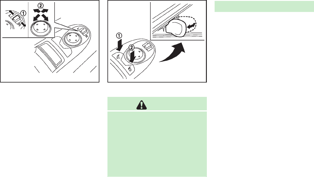
SPA2739
Adjusting outside mirrors
The outside mirror control switch is located
on the armrest.
The outside mirror will operate only when
the ignition switch is in the ACC or ON
position.
Move the switch right or left to select the
right or left side mirror
*
1
, then adjust
using the control switch
*
2
.
Defrosting outside mirrors
The outside mirrors will be heated when
the rear window defroster switch is oper-
ated.
SPA2738
Foldable outside mirrors
CAUTION
.Do not touch the mirrors while they are
moving. Your hand may be pinched, and
the mirror may malfunction.
.Do not drive with the mirrors stored. You
will be unable to see behind the vehicle.
.If the mirrors were folded or unfolded by
hand, there is a chance that the mirror
will move forward or backward during
driving. If the mirrors were folded or
unfolded by hand, be sure to adjust
them again electrically before driving.
The outside rearview mirror remote control
operates when the ignition switch is in the
“ACC”or “ON”position.
To fold the outside rearview mirrors, push
the outside rearview mirror folding switch
to the CLOSE position
*
1
. To unfold, push
to the OPEN position
*
2
.
If mirrors are manually operated or
bumped, the mirror body can become
loose at the pivot point. To correct electro-
nic mirror operation, cycle mirrors by
pushing the “CLOSE”switch until comple-
tely closed, then push “OPEN”until mirror
is in the open position.
Reverse tilt-down feature
When backing up the vehicle, the right and
left outside mirrors will turn downward
automatically to provide better rear visibi-
lity.
1. Push the ignition switch to the ON
position.
2. Move the selector lever to the R
(Reverse) position.
3. Select the right or left side mirror by
operating the outside mirror control
Pre-driving checks and adjustments 3-27

3-28 Pre-driving checks and adjustments
switch.
4. The outside mirror surface moves
downward.
When one of the following conditions has
occurred, the outside mirror surface will
return to its original position.
.The selector lever is moved to any
position other than R (Reverse).
.The outside mirror control switch is set
to the center position.
.The ignition switch is pushed to the OFF
position.
Automatic anti-glare
The outside rearview mirrors are designed
so that its automatically change reflection
according to the intensity of the headlights
of the vehicle following you.
The anti-glare system will be automatically
turned on when you push the ignition
switch to the “ON”position.
SIC3869
VANITY MIRROR
To use the front vanity mirror, pull down
the sun visor and pull up the cover.
The automatic drive positioner system has
four features:
.Entry/exit function
.Seat synchronization function
.Memory storage
.Setting memory function
ENTRY/EXIT FUNCTION
This system is designed so that the driver’s
seat and steering column will automati-
cally move when the selector lever is in the
P (Park) position. This allows the driver to
get into and out of the driver’s seat more
easily.
The driver’s seat will slide backward and
the steering wheel will move up when the
driver’s door is opened with the ignition
switch in the LOCK position.
The driver’s seat and steering wheel will
return to the previous positions when the
ignition switch is pushed to the ACC
position.
The driver’s seat will not return to the
previous positions if the seat or steering
adjusting switch is operated when the seat
is at the exit position.
AUTOMATIC DRIVE POSITIONER

Cancel or activate entry/exit func-
tion
The selector lever must be in the P (Park)
position with the ignition switch in the OFF
position.
The entry/exit function can be activated or
canceled by pressing and holding the SET
switch for more than 10 seconds.
The indicator lights on the memory
switches (1 and 2) will blink once when
the function is canceled, and the indicator
lights will blink twice when the function is
activated. Note that the indicator lights
may illuminate after 5 seconds while
holding the SET switch. This indicates
readiness for linking the Intelligent Key to
a stored memory position. Keep the SET
switch pressed for more than 10 seconds
to turn on or off the entry/exit function.
The entry/exit function can also be acti-
vated or canceled if the “Lift Steering
Wheel on Exit”key or “Slide Driver Seat
Back on Exit”key is turned to ON or OFF in
the “Comfort settings”settings. (See “Ve-
hicle information and settings”in the “4.
Monitor, climate, audio, phone and voice
recognition systems”section.)
Initialize entry/exit function
If the battery cable is disconnected, or if
the fuse opens, the entry/exit function will
not work though this function was set on
before. In such a case, after connecting the
battery or replacing with a new fuse, open
and close the driver’s door more than two
times after the ignition switch is turned
from the ON position to the LOCK position.
The entry/exit function will be activated.
SPA2792
SEAT SYNCHRONIZATION FUNCTION
The seat synchronization function automa-
tically adjusts the positions of the steering
wheel and outside mirrors when the seat is
adjusted using the power seat switches.
However, the steering wheel and outside
mirrors will not move if the seat is adjusted
over the maximum thresholds. The system
considers that the steering wheel and
outside mirror adjustments are not neces-
sary because the seat may not be adjusted
for the driving position. Note that the
function is set to disabled as the factory
default setting.
Pre-driving checks and adjustments 3-29

indicator light will stay on for approxi-
mately 5 seconds.
.If the battery cable is disconnected, or if
the fuse opens, the memory will be
canceled. In this case, reset the desired
position using the previous procedure.
.If optional Intelligent Keys are added to
your vehicle, the memory storage pro-
cedure to switch 1 or 2 and linking
Intelligent Key procedure to a stored
memory position should be performed
again for each Intelligent Key. For
additional Intelligent Key information,
see “Keys”earlier in this section.
Selecting the memorized position
1. Move the selector lever to the P (Park)
position.
2. Use one of the following methods to
move the driver’s seat, the outside
mirrors and the steering wheel.
.
Push the ignition switch to the ON
position and push the memory
switch (1 or 2) fully for at least 1
second.
.
Within 45 seconds of opening the
driver’s door, push the memory
switch (1 or 2) fully for at least 1
second.
The driver’s seat, steering column
and outside mirrors will move to the
memorized position with the indica-
tor light flashing, and then the light
will stay on for approximately 5
seconds.
SETTING MEMORY FUNCTION
The status of the following settings can be
linked to the Intelligent Key and the
memorized settings can be available for
each Intelligent Key.
.Climate control system
.Navigation system (if so equipped)
.Audio system
To use the memory function, lock the doors
with the Intelligent Key that is linked to the
settings.
To enable the memorized settings:
1. Carry the Intelligent Key that is linked
to the settings, and unlock the doors by
pushing the driver’s door handle re-
quest switch or UNLOCK button on
the Intelligent Key.
2. Push the ignition switch to the “ON”
position. “Connection with the key has
been done”will be displayed on the
screen and the memorized settings are
available (only when a new Intelligent
Key is used).
SYSTEM OPERATION
The automatic drive positioner system will
not work or will stop operating under the
following conditions:
.When the vehicle speed is above 4 MPH
(7 km/h).
.When the adjusting switch for the
driver’s seat and steering column is
turned on while the automatic drive
positioner is operating.
.When the memory switch 1 or 2 is not
pushed for at least 1 second.
.When the seat, steering column and
outside mirrors have already been
moved to the memorized position.
.When no position is stored in the
memory switch.
.When the engine is started while
moving the automatic drive positioner.
.When the selector lever is moved from
the P (Park) position to any other
position. (However, it will not be
canceled if the switch is pushed while
the seat and steering column are
returning to the previous positions
(entry/exit function).)
Pre-driving checks and adjustments 3-31
3-32 Pre-driving checks and adjustments
.When the driver’s door remains open
for more than 45 seconds and the
ignition switch is not in the ON posi-
tion.
.The seat synchronization function is
automatically disabled if the outside
mirrors or steering wheel reaches its
maximum adjustment.
.The seat synchronization function will
not operate if the seat is adjusted over
one of the following maximum thresh-
olds:
—Seat sliding: 3.0 in (76 mm)
—Seatback reclining: 9.1 degrees
—Seat lifter (rear side): 0.8 in (20 mm)

4 Monitor, climate, audio, phone and voice recogni-
tion systems
Safety note.......................................................... 4-3
Center multi-function control panel...................... 4-4
How to use INFINITI controller.......................... 4-6
How to use touch screen (models with
navigation system) .......................................... 4-6
Menu options (models with
navigation system) .......................................... 4-8
How to select menus on the screen................. 4-9
Vehicle information and settings........................ 4-10
How to use STATUS button ............................ 4-10
How to use brightness control and display
ON/OFF button .............................................. 4-10
How to use DISP button ................................ 4-10
How to use ECON button (models without
navigation system) ........................................ 4-10
How to use INFO button ................................ 4-10
How to use SETTING button........................... 4-16
RearView monitor .............................................. 4-27
How to read displayed lines.......................... 4-27
How to park with predictive course lines ....... 4-28
Difference between predictive and
actual distances ............................................ 4-29
Predictive course line settings....................... 4-32
How to adjust screen .................................... 4-32
Sonar indicator (if so equipped) .................... 4-33
Operating tips.............................................. 4-33
Ventilators ........................................................ 4-34
Automatic climate control.................................. 4-34
Automatic climate control (Type A)............... 4-37
Automatic climate control (Type B)............... 4-41
Forest Air
®
(if so equipped) ......................... 4-43
Operating tips.............................................. 4-47
Linking intelligent key.................................. 4-48
In-cabin microfilter....................................... 4-48
Servicing climate control.............................. 4-48
Audio system .................................................... 4-49
Audio operation precautions ........................ 4-49
FM-AM-SAT radio with Compact Disc
(CD) player................................................... 4-64
DVD (Digital Versatile Disc) player operation
(models with navigation system).................. 4-68
USB input operation .................................... 4-71
Bluetooth
®
streaming audio (models with
navigation system)....................................... 4-76
iPod
®
player operation ................................ 4-81
CD/DVD/USB memory care and cleaning...... 4-83
Steering-wheel-mounted controls
for audio ..................................................... 4-84
Antenna....................................................... 4-85
Car phone or CB radio....................................... 4-86
Bluetooth
®
Hands-Free Phone System
(models with navigation system)........................ 4-86
Regulatory information .................................. 4-88
Voice commands ........................................... 4-88
Control buttons ............................................. 4-88
Connecting procedure.................................... 4-89
Phone selection............................................. 4-89
Vehicle phonebook........................................ 4-89
Making a call ................................................ 4-92
Receiving a call ............................................. 4-93
During a call ................................................. 4-94
Phone setting................................................ 4-94
Troubleshooting guide................................... 4-96
Bluetooth
®
Hands-Free Phone System
(models without navigation system)................... 4-97
Regulatory information .................................. 4-98
Control buttons ............................................. 4-99
Voice recognition system ............................. 4-99
Pairing procedure ...................................... 4-104
Phonebook registration.............................. 4-105
Making a call............................................. 4-106
Receiving a call.......................................... 4-106
During a call.............................................. 4-106
Phone settings........................................... 4-107
Voice adaptation mode .............................. 4-110
INFINITI Voice Recognition system
(models with navigation system) ..................... 4-111
INFINITI Voice Recognition
standard mode .......................................... 4-112
Using the system....................................... 4-115
INFINITI Voice Recognition alternate
command mode......................................... 4-124
Using the system....................................... 4-133
Troubleshooting guide ............................... 4-139

WARNING
.Do not disassemble or modify this
system. If you do, it may result in
accidents, fire, or electric shock.
.Do not use this system if you notice any
abnormality, such as a frozen screen or
lack of sound. Continued use of the
system may result in accident, fire or
electric shock.
.In case you notice any foreign object in
the system hardware, spill liquid on it,
or notice smoke or smell coming from it,
stop using the system immediately and
contact your nearest INFINITI retailer.
Ignoring such conditions may lead to
accidents, fire, or electric shock.
.Park the vehicle in a safe location and
apply the parking brake to view the
images on the front center display
screen.
Do not attempt to operate the system in
extreme temperature conditions [below
−48F(−208C) and above 1588F (708C)].
Operating this system under these condi-
tions may result in system malfunctions.
Monitor, climate, audio, phone and voice recognition systems 4-3
SAFETY NOTE

4-4 Monitor, climate, audio, phone and voice recognition systems
SAA2953
Models with navigation system
1. “DISP”display setting button (P.4-10)
2, 5, 6.
For navigation system control buttons
(Refer to the separate Navigation
System Owner’s Manual.)
3. “INFO”vehicle and navigation infor-
mation button (P.4-10)
4. “SETTING”button (P.4-16)
7. INFINITI controller (P.4-6)
8. “STATUS”status display button
(P.4-10)
9. “OFF”brightness control and
display ON/OFF button (P.4-10)
CENTER MULTI-FUNCTION CONTROL PANEL

4-6 Monitor, climate, audio, phone and voice recognition systems
SAA2955
Models with navigation system
SAA2956
Models without navigation system
HOW TO USE INFINITI CONTROLLER
Choose an item on the display by rotating
or pushing the center dial
*
2
upward/
downward, and push the ENTER button
*
1
for operation.
If you push the BACK button
*
3
before the
setup is completed, the setup will be
canceled and/or the display will return to
the previous screen.
After the setup is completed, push the
BACK button
*
3
and return to the previous
screen.
For the VOICE button
*
4
functions, refer to
the separate Navigation System Owner’s
Manual.
HOW TO USE TOUCH SCREEN
(models with navigation system)
CAUTION
.The glass screen on the liquid crystal
display may break if it is hit with a hard
or sharp object. If the glass screen
breaks, do not touch it. Doing so could
result in an injury.
.To clean the display, use a soft, dry
cloth. If additional cleaning is necessary,
use a small amount of neutral detergent
with a soft cloth. Never use a rough
cloth, alcohol, benzine, thinner or any
kind of solvent or paper towel with a
chemical cleaning agent. They will
scratch or deteriorate the panel.
.Do not splash any liquid such as water
or car fragrance on the display. Contact
with liquid will cause the system to
malfunction.
To ensure safe driving, some functions
cannot be operated while driving.
The on-screen functions that are not
available while driving will be “grayed
out”or muted.
Park the vehicle in a safe location and then
operate the navigation system.
WARNING
.ALWAYS give your full attention to
driving.
.Avoid using vehicle features that could
distract you. If distracted, you could lose
control of your vehicle and cause an
accident.

SAA2473
Example
Touch screen operation
With this system, the same operations as
those for the INFINITI controller are possi-
ble using the touch screen operation.
Selecting the item:
Touch an item to select it. To select the
“Audio”settings, touch the “Audio”area
*
1
on the screen.
Touch the “BACK”
*
2
key to return to the
previous screen.
SAA2474
Adjusting an item:
Touch the +
*
1
or −
*
2
key to adjust the
settings.
Touch the
*
3
or
*
4
key to move to
the previous or next item.
Touch the
*
5
or
*
6
key to move to
the previous or next page.
SAA2475
Inputting characters:
Touch the letter or number
*
1
.
There are some options available when
inputting characters.
.Uppercase:
Shows uppercase characters.
.Lowercase:
Shows lowercase characters.
.Symbols:
Shows symbols such as the question
mark (?).
.Space:
Inserts a space.
Monitor, climate, audio, phone and voice recognition systems 4-7

Vehicle information display
1. Push the INFO button on the control
panel.
2. Select an item from the INFO menu.
3. After viewing or adjusting the informa-
tion on the following screens, push the
BACK button to return to the INFO
menu.
See the separate Navigation System Own-
er’s Manual for the following items:
.Infiniti Connection
.Traffic Info
.Weather Info
.Where am I?
.Map Update
.Navigation Version
.GPS Position
When the ignition switch is in the ON
position, the “Navigation Version”key is
displayed after selecting the “Others”key.
SAA2479
Models with navigation system
SAA2480
Models with navigation system
JVH0180M
Models without navigation system
JVH0181M
Models without navigation system
Monitor, climate, audio, phone and voice recognition systems 4-11

4-12 Monitor, climate, audio, phone and voice recognition systems
Fuel Economy information
The approximate distance to empty, aver-
age fuel economy and current fuel econo-
my will be displayed for reference.
To reset the average fuel economy (Avg
Fuel Econ), select the “Reset Fuel Eco”or
“Reset”key.
If the “Fuel Eco History”or “View”key is
selected, the average fuel consumption
history will be displayed in graph form
along with the average for the previous
Reset-to-Reset period.
The unit can be converted between “US”
and “Metric”. (See “How to use SETTING
button”later in this section.)
The fuel economy information may differ
from the information displayed on the
vehicle information display. This is due to
the timing difference in updating the
information and does not indicate a mal-
function.
For models without the navigation system,
the information can be displayed by
pushing the ECON button on the
control panel.
JVH0248X
Models with navigation system
JVH0249X
Models without navigation system
TIRE PRESSURE information
WARNING
.When a spare tire is mounted or a wheel
is replaced, tire pressure will not be
indicated, the TPMS will not function
and the low tire pressure warning light
will flash for approximately 1 minute.
The light will remain on after 1 minute.
Contact your INFINITI retailer as soon as
possible for tire replacement and/or
system resetting.
.Replacing tires with those not originally
specified by INFINITI could affect the
proper operation of the TPMS.
The tire pressure will be displayed for
reference.
The pressure indication “*** kPa”or “***
psi”on the screen means that the pressure
is being measured. After a few driving
trips, the pressure for each tire will be
displayed.
For models with navigation system, to
change the measurement units, select the
“Select Units”key with the INFINITI con-
troller and push the ENTER button.

The unit can be converted in the LANGUAGE
& UNITS settings display. (See “How to use
SETTING button”later in this section for
details.)
In case of low tire pressure, LOW PRES-
SURE information will be displayed on the
screen. Check the pressure of all tires.
Tire pressure rises and falls depending on
the heat caused by the vehicle’s traveling
condition and the temperature.
After tire rotation is performed, tire pres-
sure will not be displayed in the actual tire
position. Drive the vehicle at over 25 MPH
(40 km/h) for approximately 10 minutes to
reset the display.
For more details about the Tire Pressure
Monitoring System (TPMS), see “Tire Pres-
sure Monitoring System (TPMS)”in the “5.
Starting and driving”section.
When the ignition switch is in the ACC
position, the “Tire Pressure”key is not
displayed.
SAA2481
SAA2482
Models with navigation system
JVH0183M
JVH0184M
Models without navigation system
Monitor, climate, audio, phone and voice recognition systems 4-13

4-14 Monitor, climate, audio, phone and voice recognition systems
Maintenance information
The maintenance intervals can be dis-
played for the engine oil, oil filter, tire
and other reminders.
To set a maintenance interval, select a
preferred item from the list.
You can also set to display a message to
remind you that the maintenance needs to
be performed.
The following example shows how to set
the engine oil maintenance information.
Use the same steps to set the other
maintenance information.
1. Set the interval (mileage) of the main-
tenance schedule. To determine the
recommended maintenance interval,
refer to your “INFINITI Service and
Maintenance Guide”.
2. To display the reminder automatically
when the desired distance is reached,
select the “Reminder”key.
3. Reset the driving distance to the new
maintenance schedule.
4. To return to the previous screen, push
the BACK button.
The unit can be converted between “US”
and “Metric”. (See “How to use SETTING
button”later in this section.)
SAA3003
Models with navigation system
SAA1611
Models without navigation system

4-16 Monitor, climate, audio, phone and voice recognition systems
SAA3009
Models with navigation system
JVH0250X
Models without navigation system
HOW TO USE SETTING BUTTON
The display as illustrated will appear when
the SETTING button is pushed.
For navigation settings, refer to the sepa-
rate Navigation System Owner’s Manual.
SAA2485
Models with navigation system
JVH0251X
Models without navigation system
Audio settings
The display as illustrated will appear when
pushing the SETTING button and selecting
the “Audio”key.
Bass/Treble/Balance/Fade:
To adjust the speaker tone quality and
sound balance, select the “Bass”,“Treble”,
“Balance”or “Fade”key and adjust it with
the INFINITI controller.
These items can also be adjusted by
pushing and turning the AUDIO knob.
Speed Sensitive Vol. (if so equipped):
The audio system’s volume is increased
with the vehicle speed. Select the “Speed
Sensitive Vol.”key and adjust the effect
level with the INFINITI controller. The Speed
Sensitive Volume function is turned off
when the level is set to OFF. Increasing the
value will cause the volume to increase
faster with vehicle speed.
Precision Phased Audio (if so equipped):
When this item is turned to ON, super high
pitch sound and super low pitch sound are
emphasized and midrange sound is played
naturally.
BOSE
®
Centerpoint
®
(if so equipped):
When this item is turned to ON, an exciting
surround sound effect is generated from a
traditional stereo recording.
BOSE
®
AudioPilot
®
(if so equipped):
BOSE
®
AudioPilot
®
adjusts the volume and
sound quality depending on the changes of
the vehicle speeds and the noise picked up
by the microphone. It compensates for
noise for different road surface conditions
and open windows.
Surround Effect (if so equipped):
To adjust the surround sound volume,
select “Surround Effect”key and adjust it
with the INFINITI controller.
DivX
®
Registration Code (models with
navigation system):
The registration code for a device that is
used to download DivX
®
files will be
displayed on the screen. If a disc is loaded
or a USB memory is connected to the audio
system, this function will not be activated.
Display Album Cover Art (models with
navigation system):
When this item is turned to ON, the album
cover image is displayed when playing
iPod
®
or MP3 music files through a CD,
DVD or USB memory. When the image is
not properly embedded in the file or
device, the image will not be displayed.
Phone settings (models with navi-
gation system)
For details of the “Phone”settings, see
“Bluetooth
®
Hands-Free Phone System
(models with navigation system)”later in
this section.
Bluetooth
®
settings (models with
navigation system)
For details of the “Bluetooth
®
”settings,
see “Bluetooth
®
Hands-Free Phone System
(models with navigation system)”later in
this section or “Bluetooth
®
streaming
audio (models with navigation system)”
later in this section.
Monitor, climate, audio, phone and voice recognition systems 4-17

4-24 Monitor, climate, audio, phone and voice recognition systems
Language & Units settings
The Language & Units settings display will
appear when pushing the SETTING button,
selecting the “Language & Units”key with
the INFINITI controller and pushing the
ENTER button.
For models with the navigation system,
select the “Others”key to show the
“Language & Units”key.
Select Language:
Select the “Select Language”key. Choose
“English”,“Français”or “Español”for your
favorite display appearance.
If you select the “Français”key, the French
language will be displayed, so please use
the French Owner’s Manual. To obtain a
French Owner’s Manual, see “Owner’s
Manual/Service Manual order information”
in the “9. Technical and consumer informa-
tion”section.
Select Units:
Select the “Select Units”key. Choose “US”
(Mile, 8F, MPG) or “Metric”(km, 8C, L/100
km) for your favorite display appearance.
Select Units (Tire Pressure):
Choose the “Select Units (Tire Pressure)”
key and push the ENTER button. From the
following display, select “kPa”or “psi”.
When the ignition switch is in the ACC
position, the “Select Units (Tire Pressure)”
key is not displayed.
Voice Recognition settings (models
with navigation system)
For details about the “Voice Recognition”
settings, see “INFINITI Voice Recognition
system (models with navigation system)”
later in this section.
Camera settings
The “CAMERA”screen will appear when
selecting the “Camera”key with the
INFINITI controller and pushing the ENTER
button.
For the details about the camera system
operation, see “RearView monitor”later in
this section.
Infiniti Connection (models with
navigation system)
The information feeds history and the UNIT
ID can be confirmed and Infiniti Connection
history can be deleted. For further details,
see the separate Navigation System Own-
er’s Manual.
JVH0141M
Models with navigation system
Sonar settings (models with navi-
gation system)
The “Sonar”screen will appear when
selecting the “Sonar”key with the INFINITI
controller and pushing the ENTER button.
For the details of the sonar system opera-
tion, see “Sonar system”in the “5.
Starting and driving”section.
Sonar Display:
When this item is turned ON, the corner/
center sonar indicator will appear when the
sonar detect rear obstacles near the
bumper.

4-26 Monitor, climate, audio, phone and voice recognition systems
SAA2492
Full Screen Display:
The full screen display will appear when
selecting the “Full Screen Display”key.
To operate the Image Viewer or to change
the settings, select the desired key using
the INFINITI controller.
.(Start)
Select the “”key to start playing
the slideshow.
.(Stop)
Select the “”key to stop the
slideshow.
.(Next)
Select the “”key to display the next
file.
.(Previous)
Select the “”key to display the
previous file.
Setting the Image Viewer:
The Image Viewer setting display will
appear when selecting the “Settings”key
on the full screen display. The following
settings are available for the full screen
display.
.Slideshow Speed
Select the “Slideshow Speed”key.
From the following display, select the
changing time from 5, 10, 30, 60
seconds or “No Auto Change”.
.Slideshow Order
Select the “Slideshow Order”key. From
the following display, select “Random”
or “Order List”. For “Order List”, the
image order is the order of the files as
stored on the USB memory.
Operating tips:
.Only files that meet the following
conditions will be displayed.
—Image type: JPEG
—File Extensions: *.jpg, *jpeg
—Maximum Resolution: 2048 61536
pixels
—Maximum Size: 2-MB
—Colors: 32768 (15-bit)
—Maximum File Name lengths: 253-
Bytes
—Maximum Folders: 500
—Maximum Images per Folder: 1024
.If an electronic device (such as a digital
camera) is directly connected to the
vehicle using a USB cable, no image
will be displayed on the screen.
.If the file name is too long, some file
names may not be entirely displayed.
.When the total number of characters in
the file name exceeds 100 or if 1 file
name in a directory exceeds 100
characters, all files will show a shor-
tened 8-character version. The image
will still be displayed when selected.

When the selector lever is shifted into the
“R”(Reverse) position, the monitor display
shows view to the rear of the vehicle.
The system is designed as an aid to the
driver in detecting large stationary objects
to help avoid damaging the vehicle. The
system will not detect small objects below
the bumper and may not detect objects
close to the bumper or on the ground.
WARNING
.The RearView camera is a convenience
but it is not a substitute for proper
backing up. Always turn and check that
it is safe to do so before backing up.
Always back up slowly.
.Objects viewed in the RearView Monitor
differ from actual distance because a
wide-angle lens is used. Objects in the
RearView Monitor will appear visually
opposite like ones viewed in the inside
and outside mirrors.
.Make sure that the trunk is securely
closed when backing up.
.Underneath the bumper and the corner
areas of the bumper cannot be viewed on
the RearView monitor because of its
monitoring range limitation.
.Do not put anything on the RearView
camera. The RearView camera is in-
stalled above the license plate.
.When washing the vehicle with high-
pressure water, be sure not to spray it
around the camera. Otherwise, water
may enter the camera unit causing water
condensation on the lens, a malfunction,
fire or an electric shock.
.Do not strike the camera. It is a precision
instrument. Otherwise, it may malfunc-
tion or cause damage resulting in a fire
or an electric shock.
CAUTION
There is a plastic cover over the camera. Do
not scratch the cover when cleaning dirt or
snow from the cover.
SAA1896
HOW TO READ DISPLAYED LINES
Guiding lines which indicate the vehicle
width and distances to objects with re-
ference to the bumper line
*
A
are dis-
played on the monitor.
Distance guide lines:
Indicate distances from the bumper.
.Red line
*
1
: approx. 1.5 ft (0.5 m)
.Yellow line
*
2
: approx. 3 ft (1 m)
.Green line
*
3
: approx. 7 ft (2 m)
.Green line
*
4
: approx. 10 ft (3 m)
Vehicle width guide lines
*
5
:
Indicate the vehicle width when backing
Monitor, climate, audio, phone and voice recognition systems 4-27
REARVIEW MONITOR

4-28 Monitor, climate, audio, phone and voice recognition systems
up.
Predictive course lines
*
6
:
Indicate the predictive course when back-
ing up. The predictive course lines will be
displayed on the monitor when the selector
lever is in the “R”(Reverse) position and
the steering wheel is turned. The predictive
course lines will move depending on how
much the steering wheel is turned and will
not be displayed while the steering wheel
is in the neutral position.
HOW TO PARK WITH PREDICTIVE
COURSE LINES
WARNING
.Always turn and check that it is safe to
park your car before backing up. Always
back up slowly.
.Use the displayed lines as a reference.
The lines are highly affected by the
number of occupants, fuel level, vehicle
position, road condition and road grade.
.If the tires are replaced with different
sized tires, the predictive course line
may not be displayed correctly.
.On a snow-covered or slippery road,
there may be a difference between the
predictive course line and the actual
course line.
.If predictive course lines are displayed
incorrectly, drive the vehicle on a
straight road for 110 yd (100 m) at a
speed of above 20 MPH (30 km/h).
.The displayed lines will appear slightly
off to the right because the RearView
camera is not installed in the rear center
of the vehicle.
.The distance guide line and the vehicle
width guide line should be used as a
reference only when the vehicle is on a
level paved surface. The distance viewed
on the monitor is for reference only and
may be different than the actual distance
between the vehicle and displayed ob-
jects.
.When backing up the vehicle up a hill,
objects viewed in the monitor are further
than they appear. When backing up the
vehicle down a hill, objects viewed in the
monitor are closer than they appear. Use
the inside mirror or glance over your
shoulder to properly judge distances to
other objects.
The vehicle width and predictive course
lines are wider than the actual width and
course.

4-32 Monitor, climate, audio, phone and voice recognition systems
may hit the object when backing up to the
position
*
A
if the object projects over the
actual backing up course.
SAA2404
Models with navigation system
SAA2606
Models without navigation system
PREDICTIVE COURSE LINE SETTINGS
To turn ON or OFF the predictive course line
display, push the SETTING button, select
the “Camera”key and push the ENTER
button.
.Predictive Course Lines
When this item is turned to ON, the
predictive course lines will be displayed
on the monitor when the selector lever is in
the “R”(Reverse) position.
HOW TO ADJUST SCREEN
To adjust the Display ON/OFF, Brightness,
Tint, Color, Contrast and Black Level of the
RearView monitor, push the SETTING but-
ton with the RearView monitor on, select
the “Display”key on the screen and select
the item key and adjust the level using the
INFINITI controller.
Do not adjust the Brightness, Tint, Color,
Contrast and Black Level of the RearView
monitor while the vehicle is moving. Make
sure the parking brake is firmly applied
and the engine is not running.
SONAR INDICATOR (if so equipped)
When the “Sonar Display”key is ON, the
sonar indicator will appear in the display.
(See“How to use SETTING button”earlier in
this section and “Sonar system”in the “5.
Starting and driving”section.)
OPERATING TIPS
.When the selector lever is shifted to the
“R”(Reverse) position, the monitor
screen automatically changes to the
RearView monitor mode. However, the
radio can be heard.
.It may take some time until the Rear-
View monitor is displayed after the
selector lever has been shifted to “R”
from another position or to another
position from “R”. Objects may be
distorted momentarily until the Rear-
View monitor screen is displayed com-
pletely.
.When the temperature is extremely high
or low, the screen may not clearly
display objects. This is not a malfunc-
tion.
.When strong light directly enters the
camera, objects may not be displayed
clearly. This is not a malfunction.
.Vertical lines may be seen in objects on
the screen. This is due to strong
reflected light from the bumper. This
is not a malfunction.
.The screen may flicker under fluores-
cent light. This is not a malfunction.
.The colors of objects on the RearView
monitor may differ somewhat from
those of the actual object.
.Objects on the monitor may not be clear
in a dark place or at night. This is not a
malfunction.
.If dirt, rain or snow attaches to the
camera, the RearView monitor may not
clearly display objects. Clean the cam-
era.
.Do not use alcohol, benzine or thinner
to clean the camera. This will cause
discoloration. To clean the camera,
wipe with a cloth dampened with
diluted mild cleaning agent and then
wipe with a dry cloth.
.Do not damage the camera as the
monitor screen may be adversely af-
fected.
.Do not use wax on the camera window.
Wipe off any wax with a clean cloth
dampened with mild detergent diluted
with water.
Monitor, climate, audio, phone and voice recognition systems 4-33

AUTOMATIC CLIMATE CONTROL
(Type A)
Automatic operation
Cooling and/or dehumidified heating
(AUTO):
This mode may be used all year round. The
system works automatically to control the
inside temperature, air flow distribution
and fan speed after the preferred tempera-
ture is set manually.
1. Push the “AUTO”button on. (The
indicator on the button will illuminate
and AUTO will be displayed.)
2. Push the temperature control button
(driver side) to set the desired tem-
perature.
.
The temperature can be set within
the following range.
—For U.S.: 60 to 908F (16 to 328C)
—For Canada: 64 to 908F (18 to
328C)
.
The temperature of the passenger
compartment will be maintained
automatically. Air flow distribution
and fan speed will also be controlled
automatically.
3. To turn off the climate control system,
push the “OFF”button.
A visible mist may be seen coming from the
ventilators in hot, humid conditions as the
air is cooled rapidly. This does not indicate
a malfunction.
Dehumidified defrosting or defogging:
1. Push the front defroster “”button.
(The indicator light on the button will
come on.)
2. Push the temperature control button
(driver side) to set the desired tem-
perature.
.
The temperature can be set within
the following range.
—For U.S.: 60 to 908F (16 to 328C)
—For Canada: 64 to 908F (18 to
328C)
.
The temperature of the passenger
compartment will be maintained
automatically. Air flow distribution
and fan speed will also be controlled
automatically.
3. To turn off the climate control system,
push the “OFF”button.
.To quickly remove ice from the outside
of the windows, push the fan speed
increase “”button and set it to
the maximum position.
.As soon as possible after the wind-
shield is clean, push the “AUTO”button
to return to the auto mode.
.When the front defroster “”button
is pushed, the air conditioner will
automatically be turned on at outside
temperatures above 238F(−58C) to
defog the windshield, and the air
recirculate mode will automatically be
turned off.
Outside air is drawn into the passenger
compartment to improve the defogging
performance.
Manual operation
Fan speed control:
Push the fan speed increase “”or
decrease “”button to manually control
the fan speed.
Push the “AUTO”button to return to
automatic control of the fan speed.
Temperature control:
Turn the temperature control dial to set the
desired temperature.
.The temperature can be set within the
following range.
Monitor, climate, audio, phone and voice recognition systems 4-37

4-38 Monitor, climate, audio, phone and voice recognition systems
—For U.S.: 60 to 908F (16 to 328C)
—For Canada: 64 to 908F (18 to 328C)
Air recirculation:
Push the air recirculation “”button to
change the air circulation mode. When the
indicator light illuminates, the flowing air
is recirculated inside the vehicle.
The air recirculation mode cannot be
activated when the air conditioner is in
the front defrosting mode “”.
Outside air circulation:
Push the outside air circulation “”
button to change the air circulation mode.
When the indicator light illuminates, the
flowing air is drawn from outside the
vehicle.
Automatic air intake control:
To set the automatic control mode, perform
one of the following operations.
.When the outside air circulation mode
is on, push and hold the outside air
circulation “”button for more than
2 seconds.
.When the air recirculation mode is on,
push and hold the air recirculation
“”button for more than 2 seconds.
When setting the automatic control mode,
both indicator lights will blink twice
indicating that the system is in the
automatic control mode.
Air flow control:
Pushing the “”button selects the air
outlet to:
: Air flows from center and side ventilators.
: Air flows from center and side ventilators and
foot outlets.
: Air flows mainly from foot outlets.
: Air flows from defroster and foot outlets.
SAA3002
Models with navigation system
JVH0054M
Models without navigation system

4-40 Monitor, climate, audio, phone and voice recognition systems
SAA2951
Type B
1. “”front defroster button
2. “”rear window defroster button
(See “Rear window and outside mirror
defroster switch”in the “2. Instru-
ments and controls”section.)
3. “OFF”button for climate control sys-
tem
4. “”fan speed decrease button
5. “”fan speed increase button
6. “AUTO”automatic operation button
7. “”Forest button
8. “”intake air control button
9. “CLIMATE”button
10, 11.
Temperature control button (driver
side)
12. “”manual air flow control button
(driver side)
13. “”manual air flow control button
(passenger side)
14, 15.
Temperature control button (passen-
ger side)

.The Dual control mode cannot be
activated when the air conditioner is
in the front defrosting mode “”.
Automatic upper ventilator system:
1. Push the “CLIMATE”button to on.
2. Select the “Upper Vent”key and the
indicator on the screen will illuminate.
The air flow against the driver’sor
passenger’s upper body becomes gen-
tle.
In this mode, air from the center
ventilators flows both straight and
upward in order to control the cabin
temperature without blowing air di-
rectly on the occupants.
Distribution between straight and upward
flows is determined automatically by the
climate control system. If you prefer strong
air flow against your upper body, select
“Upper Vent”key to turn the indicator off.
.When the outside temperature de-
creases to approximately 148F
(−108C), the “Upper Vent”function
does not activate. The “Upper Vent”
function reactivates automatically when
the ambient temperature is 148F
(−108C) or more.
Display Forest Air
®
system setting screen:
The “Forest Air setting”screen will appear
when selecting the “Forest Air Setting”key.
For the details about the Forest Air
®
system setting operation, see “Setting
Forest Air
®
”later in this section.
Display Forest Air
®
Information screen:
The Forest Air
®
system information screen
will appear when selecting the “Forest Air
Info”key.
For details about the Forest Air
®
system
information screen, see “Forest Air
®
sys-
tem Information”later in this section.
FOREST AIR
®
(if so equipped)
The Forest Air
®
system keeps the air inside
the vehicle clean using the automatic air
intake system and automatic ventilation.
The Forest Air
®
system also makes the
inside of the vehicle more comfortable,
using a combination of the upper ventilator
and center ventilators at random.
*Forest Air
®
is a trademark of Nissan Motor
Co., Ltd.
Main operation
Push the “ ” Forest button.
(The “”and “AUTO”indicator light on
the button will illuminate.)
When the following functions and sensors
are turned on, the Forest Air
®
system
settings will activate.
.Breeze Mode
.Outside odor and exhaust gas detection
sensor
.Inside Air Quality sensor
.Auto humidity control
The fan speed and air flow is automatically
set to the AUTO position.
.The Forest Air
®
system can be adjusted
and/or activated/deactivated for each
function. For details of The Forest Air
®
system settings, see later in this
section.
.When the “”Forest button is
pushed while the air conditioner is
off, the air conditioner will automati-
cally activate.
.When the outside temperature de-
creases to approximately 328F(08C),
the outside odor and exhaust gas
detection sensor and auto humidity
control functions will not operate. The
system will not be reactivated auto-
matically even if the outside tempera-
ture reaches 328F(08C). To reactivate
Monitor, climate, audio, phone and voice recognition systems 4-43

4-44 Monitor, climate, audio, phone and voice recognition systems
the system, push the Forest button
manually. (The indicator light on the
Forest button will illuminate.)
.The air flow control is not available in
the front defroster mode. When the
“”button is pushed while the
Forest Air
®
system is turned on, the
Forest Air
®
system will turn off.
Operating tips
Breeze Mode:
When this mode is ON, fan speed fluc-
tuates during the Forest Air
®
system
operation, creating a wind breeze similar
to a natural breeze using a combination of
the upper ventilator and the center venti-
lators at random.
.Breeze Mode will activate after the
temperature of the passenger compart-
ment becomes suitable.
.This function will not operate immedi-
ately after the engine starts.
.Breeze Mode will activate when the air
flow mode is in the “”and “ ”
mode.
.This function will turn off if the fan
speed or a ventilator outlet is manually
adjusted.
.The breeze patterns may change in
accordance with the amount of sun
load.
.When operating fan speed or air flow
control while the Forest Air
®
system is
turned on, the “”indicator light on
the button will turn off automatically,
and the Breeze Mode function will turn
off.
.When the Breeze Mode function is
turned off while the Forest Air
®
system
is on, the Breeze Mode function will
remain off until the “”Forest button
is turned off and on again.
Outside odor and exhaust gas detection
sensor:
This vehicle is equipped with an outside
odor and exhaust gas detection sensor.
When the automatic intake air control is
on, the sensor detects odors and exhaust
gas, and then the system automatically
changes from the outside air circulation
mode to the recirculation mode. When the
“”Forest button is pushed, the outside
odor and exhaust gas detection sensor will
turn on.
When the Forest Air
®
system is on, for the
first 40 seconds, the recirculation mode is
selected to prevent dust, dirt and pollen
from entering the vehicle, and the system
cleans the air inside of the vehicle with
Plasmacluster
®
ion that are emitted from
the ventilator. After 40 seconds, the out-
side odor and exhaust gas sensor activates
and automatically alternates between the
recirculation mode and outside air circula-
tion mode.
.The outside odor and exhaust gas
detection sensor detects industry odors
such as pulp or chemicals, and exhaust
gas such as gasoline or diesel.
Inside Air Quality sensor:
This vehicle is equipped with an inside air
quality sensor. When the sensor detects
odor in the cabin, the system increases the
fan speed automatically. When the Forest
Air
®
system is on, the inside air quality
sensor will turn on. This function may not
work during the first 5 minutes after the
engine is started because the system is
still warming up.
.The Outside/Inside Air Mix function will
turn off when the air recirculation and
outside air circulation modes are chan-
ged manually. When the Outside/Inside
Air Mix function is not active, turn off
and on the Forest Air
®
system, the
Outside/Inside Air Mix function will

4-46 Monitor, climate, audio, phone and voice recognition systems
Select the “Auto Defogging Sensitivity”key
and select the “Slow”or “Fast”key.
When set to OFF, the automatic defogging
function will turn off.
SAA2962
Forest Air
®
system Information
The present status of the Forest Air
®
system operation and the conditions of
air inside and outside of the vehicle can be
checked.
Push the “CLIMATE”button on the instru-
ment panel and turn the display to the
“CLIMATE mode”screen and select the
“Forest Air Info”key.
1. Breeze Mode
The animation image of the Breeze
Mode function is displayed.
2. The condition of outside and inside air
The present condition of air inside and
outside the vehicle is indicated by
color.
Blue: The air is clean.
Orange: The air is not clean.
3. Outside air circulation/Air recirculation
arrow
The air flow of the outside air circula-
tion and air recirculation functions is
indicated with an arrow.
Blue arrow: The air is clean.
Orange arrow: The air is not clean.
4. Auto humidity control status
The condition of fog on the window is
displayed. When the window starts to
fog, the color turns white.
5. Outside air circulation/Air recirculation
display
When the outside air circulation or air
recirculation mode is automatically
selected, either “”or “ ” is
displayed. When the outside air circula-
tion or air recirculation mode is manu-
ally selected, either “”or “ ”,
and “Manual”are displayed.

SAA3015
Ion control
This unit generates highly concentrated
Plasmacluster
®
ion into the air blown from
the ventilators and reduces odor absorbed
into the interior trim.
The high-density Plasmacluster
®
ions gen-
erated in the air conditioner’s air stream
not only suppress airborne bacteria and
reduce the adherence of odors to the
interior trim, but also have a proven skin
moisture preserving effect.
When the air conditioner is turned on, the
system generates Plasmacluster
®
ion auto-
matically.
The amount of Plasmacluster
®
ion in-
creases according to the amount of air
flow. When the air flow is high, “”is
displayed on the screen and when the air
flow is low, the indication in the screen
changes to “”.
Plasmacluster
®
and Plasmacluster
®
ion
are trademarks of Sharp Corporation.
OPERATING TIPS
When the engine coolant temperature and
outside air temperature are low, the air
flow from the foot outlets may not operate.
This is not a malfunction. After the coolant
temperature warms up, air will flow nor-
mally from the foot outlets.
SIC2768
JVH0039X
The sensors
*
A
and
*
B
on the instrument
Monitor, climate, audio, phone and voice recognition systems 4-47

AUDIO OPERATION PRECAUTIONS
Radio
Push the ignition switch to the ACC or ON
position and push the radio band select
button to turn on the radio. If you listen to
the radio with the engine not running, the
ignition switch should be pushed to the
ACC position.
Radio reception is affected by station
signal strength, distance from radio trans-
mitter, buildings, bridges, mountains and
other external influences. Intermittent
changes in reception quality normally are
caused by these external influences.
Using a cellular phone in or near the
vehicle may influence radio reception
quality.
Radio reception:
Your INFINITI radio system is equipped with
state-of-the-art electronic circuits to en-
hance radio reception. These circuits are
designed to extend reception range, and to
enhance the quality of that reception.
However there are some general character-
istics of both FM and AM radio signals that
can affect radio reception quality in a
moving vehicle, even when the finest
equipment is used. These characteristics
are completely normal in a given reception
area, and do not indicate any malfunction
in your INFINITI radio system.
Reception conditions will constantly
change because of vehicle movement.
Buildings, terrain, signal distance and
interference from other vehicles can work
against ideal reception. Described below
are some of the factors that can affect your
radio reception.
Some cellular phones or other devices may
cause interference or a buzzing noise to
come from the audio system speakers.
Storing the device in a different location
may reduce or eliminate the noise.
SAA0306
FM radio reception:
Range: FM range is normally limited to 25
to 30 miles (40 to 48 km), with monaural
(single station) FM having slightly more
range than stereo FM. External influences
may sometimes interfere with FM station
reception even if the FM station is within
25 miles (40 km). The strength of the FM
signal is directly related to the distance
between the transmitter and receiver. FM
signals follow a line-of-sight path, exhibit-
ing many of the same characteristics as
light. For example they will reflect off
objects.
Fade and drift: As your vehicle moves away
Monitor, climate, audio, phone and voice recognition systems 4-49
AUDIO SYSTEM

4-62 Monitor, climate, audio, phone and voice recognition systems
Requirement for Supporting Video Playback:
Media CD, CD-R, CD-RW, DVD, DVD±R, DVD±RW, DVD±RW DL, USB 2.0 Memory
File Systems
CD,
CD-R,
CD-RW,
DVD,
DVD±R,
DVD±RW,
DVD±RW DL
ISO9660 LEVEL1, ISO9660 LEVEL2, Romeo, Joliet, UDF Bridge (UDF1.02
+ISO9660), UDF1.5, UDF2.0
- ISO9660 Level 3 (packet writing) is not supported.
- Files saved using the Live File System component (on a Windows Vista-
based computer) are not supported.
- VDF1.5/VDF2.0 (packet writing) is not supported.
USB Memory FAT16, FAT32
File Types
.divx, .avi Video Codecs DivX3, DivX4, DivX5, DivX6
Audio Codecs MP3, MPEG2.5 Audio Layer3, AC3, LPCM
.asf Video Codec ISO-MPEG4
Audio Codec G.726
Bit Rates .divx, .avi Maximum Average 4Mbps
Maximum Peak 8Mbps
Resolution
.divx, .avi Minimum 32 632
Maximum 720 6480
.asf Minimum 32 632
Maximum 720 6576
Bluetooth
®
Audio player (models
with navigation system)
Bluetooth
®
is a trademark
owned by Bluetooth SIG, Inc.
and licensed to Clarion Co., Ltd.
.Some Bluetooth
®
audio devices may
not be recognized by the in-vehicle
audio system.
.It is necessary to set up the wireless
connection between a compatible Blue-
tooth
®
audio device and the in-vehicle
Bluetooth
®
module before using the
Bluetooth
®
audio player.
.Operating procedure of the Bluetooth
®
audio player will vary depending on the
device. Make sure it is understood how
to operate an audio device before using
it with this system.
.The Bluetooth
®
audio player may be
stopped under the following condi-
tions:
—Receiving a hands-free call.
—Checking the connection to the
hands-free phone.
.Do not place a Bluetooth
®
audio device
in an area surrounded by metal or far
away from the in-vehicle Bluetooth
®
module to prevent tone quality degra-

Angle (DVD-VIDEO):
If the DVD contains different angles (such
as moving images), the current image
angle can be switched to another one.
Select the “Angle”key. The angle will
change each time the “+”side or “−”side
is selected.
Angle Mark (DVD-VIDEO):
When this item is turned on, an angle mark
will be shown on the bottom of the screen
if the scene can be seen from a different
angle.
Menu Skip (DVD-VIDEO):
DVD menus are automatically configured
and the contents will be played directly
when the “Menu Skip”key is turned on.
Note that some discs may not be played
directly even if this item is turned on.
CM Skip (DVD-VIDEO):
Select the “CM Skip”key. Choose the
setting time from 15, 30 or 60 seconds by
selecting the “+”side or “−”side.
DRC (DVD-VIDEO, DVD-VR):
DRC (Dynamic Range Compression) auto-
matically adjusts the soundtrack volume
level to maintain a more even sound to the
speakers.
DVD Language (DVD-VIDEO, VIDEO-CD):
Select the “DVD Language”key to open the
number entry screen. Input the number
corresponding to the preferred language
and select the “OK”key. The DVD top menu
language will be changed to the one
specified.
Display:
To adjust the image quality of the screen,
select the preferred adjustment items.
Audio:
Select the preferred language for audio.
Subtitle (DVD-VIDEO, DVD-VR):
Select the preferred language for subtitles.
Display Mode (DVD-VIDEO, VIDEO-CD, DVD-
VR):
Select from the “Full”,“Wide”,“Normal”or
“Cinema”modes.
Title List (DVD-VR):
Select the preferred title from the list.
Play Mode:
Select the preferred play mode.
PG/PL Mode (DVD-VR):
Select the “PG”or “PL”mode.
SAA2963
USB INPUT OPERATION
Audio main operation
Open the console lid and connect a USB
memory. Then, push the DISC·AUX button
repeatedly to switch to the USB memory
mode.
If the system has been turned off while the
USB memory was playing, pushing the
ON·OFF/VOL control knob will start the USB
memory.
Monitor, climate, audio, phone and voice recognition systems 4-71

4-80 Monitor, climate, audio, phone and voice recognition systems
following items.
.Shuffle
Choose “Shuffle OFF”,“Shuffle All
Tracks”and “Shuffle Group”.
.Repeat
Choose from “Repeat OFF”,“Repeat 1
Track”,“Repeat All Tracks”and “Repeat
Group”.
SAA2511
Bluetooth
®
settings
To set up the Bluetooth
®
device system to
the preferred settings, push the SETTING
button and select the “Bluetooth”key.
Bluetooth:
If this setting is turned off, the connection
between the Bluetooth
®
devices and the
in-vehicle Bluetooth
®
module will be can-
celed.
Connect Bluetooth:
Connects to the Bluetooth
®
device. See
“Connecting procedure”earlier in this
section. Up to 5 devices can be registered.
Connected Devices:
Registered devices are shown on the list.
Select a Bluetooth
®
device from the list,
the following options will be available.
.Select
Select “Select”to connect the selected
device to the vehicle. If there is a
different device currently connected,
the selected device will replace the
current device.
.Edit
Rename the selected Bluetooth
®
device
using the keypad displayed on the
screen. (See “How to use touch screen
(models with navigation system)”ear-
lier in this section.)
.Delete
Delete the selected Bluetooth
®
device.
Edit Bluetooth Info:
Change the name broadcasted by this
system over Bluetooth
®
. Change the PIN
code that is entered when connecting a
hands free device to this system.
Replace Connected Phone:
Replace the Bluetooth
®
connection with a
connected Bluetooth
®
cellular phone. For
details about Hands-Free Phone System,

4-84 Monitor, climate, audio, phone and voice recognition systems
JVH0049X
Models with navigation system
JVH0050X
Models without navigation system
1. Audio source switch
2. Menu control switch (models with
navigation system) or audio tuning
switch (models without navigation
system)
3. Back switch
4. Volume control switch
STEERING-WHEEL-MOUNTED CON-
TROLS FOR AUDIO
Menu control switch (models with
navigation system) or audio tuning
switch (models without navigation
system)
While the display is showing a MAP
(navigation systems only), STATUS or Audio
screen, tilt the switch upward or downward
to select a station, track, CD or folder. For
most audio sources, tilting the switch up/
down for more than 1.5 seconds provides a
different function than tilting up/down for
less than 1.5 seconds.
AM and FM radio:
.Tilting up/down for less than 1.5
seconds will increase or decrease the
preset station.
.Tilting up/down for more than 1.5
seconds will seek up or down to the
next station.
.Pushing the menu control switch will
show the list of preset stations.
SiriusXM Satellite Radio:
.Tilting up/down for less than 1.5
seconds will increase or decrease the
preset channel.
.Tilting up/down for more than 1.5
seconds will go to the next or previous
category.
.Pushing the menu control switch will
show the XM Menu.
iPod
®
:
.Tilting up/down for less than 1.5
seconds will increase or decrease the
track number.
.Tilting up/down for more than 1.5
seconds will skip to the next or
previous index.
.Pushing the menu control switch will
show the iPod Menu.
CD:
.Tilting up/down for less than 1.5
seconds will increase or decrease the
track number.
.Tilting up/down for more than 1.5
seconds will increase/decrease the

folder number (if playing compressed
audio files).
.Pushing the menu control switch will
show the CD Menu.
DVD (models with navigation system):
.Tilting up/down for less than 1.5
seconds will increase or decrease the
track number.
.Tilting up/down for more than 1.5
seconds will increase or decrease the
title number.
.Pushing the menu control switch will
select an item from the DVD display.
.When the transparent operation menu
appears, the switch will control the
menu.
USB:
.Tilting up/down for less than 1.5
seconds will increase or decrease the
track number.
.Tilting up/down for more than 1.5
seconds will increase/decrease the
folder number
.Pushing the menu control switch will
show the USB Menu.
Bluetooth
®
Audio (models with navigation
system):
.Tilting up/down for less than 1.5
seconds will increase or decrease the
track number.
BACK switch (models with
navigation system)
Push this switch to go back to the previous
screen or cancel the selection if it is not
completed.
Volume control switches
Push the upper (+) or lower (−) side switch
to increase or decrease the volume.
Audio source switch
Push the audio source switch to change
the mode as follows.
.Models with navigation system
AM ?FM ?SAT ?CD/DVD ?USB/
iPod
®
?Bluetooth
®
Audio
.Models without navigation system
AM ?FM ?CD ?USB/iPod
®
?SAT
ANTENNA
Window antenna
The antenna pattern is printed inside the
rear window.
CAUTION
.Do not place metalized film near the rear
window glass or attach any metal parts
to it. This may cause poor reception or
noise.
.When cleaning the inside of the rear
window, be careful not to scratch or
damage the rear window antenna.
Lightly wipe along the antenna with a
dampened soft cloth.
Monitor, climate, audio, phone and voice recognition systems 4-85

4-86 Monitor, climate, audio, phone and voice recognition systems
When installing a car phone or a CB radio
in your vehicle, be sure to observe the
following cautions, otherwise the new
equipment may adversely affect the elec-
tronic control modules and electronic con-
trol system harness.
WARNING
.A cellular phone should not be used for
any purpose while driving so full atten-
tion may be given to vehicle operation.
Some jurisdictions prohibit the use of
cellular phones while driving.
.If you must make a call while your
vehicle is in motion, the hands-free
cellular phone operational mode (if so
equipped) is highly recommended. Ex-
ercise extreme caution at all times so full
attention may be given to vehicle opera-
tion.
.If a conversation in a moving vehicle
requires you to take notes, pull off the
road to a safe location and stop your
vehicle before doing so.
CAUTION
.Keep the antenna as far away as
possible from the electronic control
modules.
.Keep the antenna wire more than 8 in
(20 cm) away from the electronic control
system harness. Do not route the anten-
na wire next to any harness.
.Adjust the antenna standing-wave ratio
as recommended by the manufacturer.
.Connect the ground wire from the CB
radio chassis to the body.
.For details, consult an INFINITI retailer.
WARNING
.Use a phone after stopping your vehicle
in a safe location. If you have to use a
phone while driving, exercise extreme
caution at all times so full attention may
be given to vehicle operation.
.If you find yourself unable to devote full
attention to vehicle operation while
talking on the phone, pull off the road
to a safe location and stop your vehicle
before doing so.
CAUTION
To avoid draining the vehicle battery, use a
phone after starting the engine.
Your INFINITI is equipped with Bluetooth
®
Hands-Free Phone System. If you are an
owner of a compatible Bluetooth
®
enabled
cellular phone, you can set up the wireless
connection between your cellular phone
and the in-vehicle phone module. With
Bluetooth
®
wireless technology, you can
make or receive a telephone call with your
cellular phone in your pocket.
CAR PHONE OR CB RADIO Bluetooth
®
HANDS-FREE PHONE SYSTEM
(models with navigation system)

4-90 Monitor, climate, audio, phone and voice recognition systems
SAA2521
1. Push the button and select the
“Vehicle Phonebook”key.
2. Select the “Add New”key at the top of
the screen.
SAA2522
3. Choose the method for entering the
phonebook entry. For this example,
select “Enter Number by Keypad”.
4. Enter the digits and select the “OK”
key. (See “How to use touch screen
(models with navigation system)”ear-
lier in this section.)
SAA2523
5. Select the “Voicetag”key to record a
name to speak when using the INFINITI
Voice Recognition system.
6. Select the “Store”key and prepare to
speak the name after the tone.
7. When the voicetag is successfully
saved, select the “OK”key to save the
phonebook entry.
8. After the phonebook entry is saved, it
will show a screen that is ready to call
the number. Press the BACK button to
return to the Vehicle Phonebook.
There are different methods to input a
phone number. Select one of the following
5-14 Starting and driving
start.
When racing the engine up to 4,000
rpm (VK56VD engine) or 4,500 rpm
(VQ37VHR engine) or more under no
load condition, the engine will enter the
fuel cut mode.
5. To stop the engine, shift the selector
lever to the P (Park) position and push
the ignition switch to the OFF position.
In preparation for the next engine start,
the engine may have a slightly delayed
shutoff after pushing the ignition
switch to the OFF position, depending
on the driving conditions (VK56VD
engine models).
NOTE:
Care should be taken to avoid situations
that can lead to potential battery dis-
charge and potential no-start conditions
such as:
1. Installation or extended use of electro-
nic accessories that consume battery
power when the engine is not running
(Phone chargers, GPS, DVD players,
etc.)
2. Vehicle is not driven regularly and/or
only driven short distances.
In these cases, the battery may need to be
charged to maintain battery health.
AUTOMATIC TRANSMISSION
The automatic transmission in your vehicle
is electronically controlled by a transmis-
sion control module to produce maximum
efficiency and smooth operation.
Shown on the following pages are the
recommended operating procedures for
this transmission. Follow these procedures
for maximum vehicle performance and
driving enjoyment.
Starting the vehicle
After starting the engine, fully depress the
foot brake pedal and push the selector
lever button before shifting the selector
lever to the R (Reverse), N (Neutral), D
(Drive) or Manual shift mode position. Be
sure the vehicle is fully stopped before
attempting to shift the selector lever.
This automatic transmission model is
designed so that the foot brake pedal
must be depressed before shifting from P
(Park) to any drive position while the
ignition switch position is ON.
The selector lever cannot be moved out of
the P (Park) position and into any of the
other gear positions if the ignition switch
is pushed to the LOCK, OFF or ACC
position.
DRIVING THE VEHICLE

5-26 Starting and driving
Intervention
TM
(BSI) system”later in this
section and “Forward Collision Warning
(FCW) system”later in this section.
SSD0939
With navigation system
SSD1001
How to enable/disable the LDW
system using the settings menu
Perform the following steps to enable or
disable the LDW system.
1. Push the SETTING
*
1
button and high-
light the “Driver Assistance”key on the
display using the INFINITI controller.
Then push the ENTER
*
2
button.
2. Highlight the “Driver Assistance Warn-
ings”key, and push the ENTER
*
2
button.

SSD0984
System operation
1. System set display with vehicle ahead
2. System set display without vehicle
ahead
WARNING
Normally when controlling the distance to a
vehicle ahead, this system automatically
accelerates or decelerates your vehicle
according to the speed of the vehicle ahead.
Depress the accelerator to properly accel-
erate your vehicle when acceleration is
required for a lane change. Depress the
brake pedal when deceleration is required to
maintain a safe distance to the vehicle
ahead due to its sudden braking or if a
vehicle cuts in. Always stay alert when
using the ICC system.
The driver sets the desired vehicle speed
based on the road conditions. The ICC
system maintains the set vehicle speed,
similar to standard cruise control, as long
as no vehicle is detected in the lane ahead.
The ICC system displays the set speed.
Vehicle detected ahead:
When a vehicle is detected in the lane
ahead, the ICC system decelerates the
vehicle by controlling the throttle and
applying the brakes to match the speed
of a slower vehicle ahead. The system then
controls the vehicle speed based on the
speed of the vehicle ahead to maintain the
driver selected distance.
The stoplights of the vehicle come on
when braking is performed by the ICC
system.
When the brake operates, a noise may be
heard. This is not a malfunction.
When a vehicle ahead is detected, the
vehicle ahead detection indicator comes
on. The ICC system will also display the set
speed and selected distance.
Vehicle ahead not detected:
When a vehicle is no longer detected
ahead, the ICC system gradually acceler-
ates your vehicle to resume the previously
set vehicle speed. The ICC system then
maintains the set speed.
When a vehicle is no longer detected the
vehicle ahead detection indicator turns off.
If a vehicle ahead appears during accel-
eration to the set vehicle speed or any time
Starting and driving 5-59

5-76 Starting and driving
SSD0939
With navigation system
SSD1001
How to enable/disable the DCA system
using the settings menu:
Perform the following steps to enable or
disable the DCA system.
1. Push the SETTING
*
1
button and high-
light the “Driver Assistance”key on the
display using the INFINITI controller.
Then push the ENTER
*
2
button.
2. Highlight the “Dynamic Assistance Set-
tings”key, and push the ENTER
*
2
button.
SSD1002
3. Highlight the “Distance Control Assist”
key, select ON (enabled) or OFF (dis-
abled) and push the ENTER
*
2
button.
For the LDP and BSI systems, see “Lane
Departure Warning (LDW) system/Lane
Departure Prevention (LDP) system”earlier
in this section and “Blind Spot Warning
(BSW) system/Blind Spot Intervention
TM
(BSI) system”earlier in this section.
Produkt Specifikationer
| Mærke: | Infiniti |
| Kategori: | Personbil |
| Model: | M - 2013 |
Har du brug for hjælp?
Hvis du har brug for hjælp til Infiniti M - 2013 stil et spørgsmål nedenfor, og andre brugere vil svare dig
Personbil Infiniti Manualer

6 Juli 2024
5 Juli 2024
5 Juli 2024
4 Juli 2024
Personbil Manualer
- Personbil Toyota
- Personbil Opel
- Personbil Mazda
- Personbil Audi
- Personbil Volkswagen
- Personbil Smart
- Personbil Lexus
- Personbil Volvo
- Personbil Nissan
- Personbil Skoda
- Personbil Hyundai
- Personbil Peugeot
- Personbil Fiat
- Personbil Ford
- Personbil Tesla
- Personbil Kia
- Personbil Mini
- Personbil Renault
- Personbil Vauxhall
- Personbil Alfa Romeo
- Personbil Porsche
- Personbil Land Rover
- Personbil Hella
- Personbil Maserati
- Personbil Lancia
- Personbil Mercedes
Nyeste Personbil Manualer

23 September 2024

27 August 2024
27 August 2024
27 August 2024
27 August 2024

26 August 2024
26 August 2024
26 August 2024
26 August 2024
26 August 2024