Intellinet NFC31-IR Manual
Intellinet
Overvågningskamera
NFC31-IR
Læs nedenfor 📖 manual på dansk for Intellinet NFC31-IR (112 sider) i kategorien Overvågningskamera. Denne guide var nyttig for 34 personer og blev bedømt med 4.5 stjerner i gennemsnit af 2 brugere
Side 1/112


- 2 -
Table of Contents
SAFETY AND REGULATORY NOTICES .....................................................3
1: PRODUCT OVERVIEW.........................................................................6
1.1 NETWORK CAMERAS ............................................................................6
1.2 NETWORK VIDEO SERVERS ....................................................................7
1.3 MODEL OVERVIEW .............................................................................. 7
2: SYSTEM REQUIREMENTS ...................................................................9
2.1 HARDWARE REQUIREMENTS ...................................................................9
2.2 OPERATING SYSTEM AND WEB BROWSER SUPPORT ....................................... 9
2.3 LIMITATIONS................................................................................... 10
3: HARDWARE OVERVIEW ...................................................................11
3.1 FRONT & REAR ................................................................................ 11
3.1.1 NSC15/NSC15-WG/NSC16-WG Network SOHO Cameras............. 11
3.1.2 NFC30/NFC31 Network Fixed Cameras ..................................... 13
3.1.3 NFD30 Network Dome Camera ................................................ 15
3.1.4 NBC30-IR Outdoor Network Camera......................................... 17
3.1.5 NVS30 Network Video Server .................................................. 19
3.2 DIGITAL I/O TERMINAL BLOCK CONNECTOR.............................................. 21
3.3 PACKAGE CONTENTS.......................................................................... 22
4: INSTALLATION ................................................................................23
4.1 CONNECTING TO THE CAMERA .............................................................. 23
4.1.1 Windows XP, Vista and Windows 7 ........................................... 24
4.1.2 MacOS.................................................................................. 41
4.1.3 Linux.................................................................................... 43
5: WEB BROWSER INTERFACE .............................................................44
5.1 LIVE VIDEO PAGE ............................................................................. 44
5.2 SETTINGS PAGE (ADMINISTRATOR MENU) ................................................ 48
5.2.1 Settings Page – Basic Settings................................................. 48
5.2.2 Settings Page – Advanced Settings .......................................... 81
6: VIDEO SURVEILLANCE SOFTWARE ................................................ 102
6.1 FUNCTION DESCRIPTION ................................................................... 102
6.2 INSTALLATION ............................................................................... 102
7: REMOTE ACCESS AND ROUTER SETUP ...........................................103
8: DEVELOPER INFORMATION ...........................................................105
9: QUESTIONS AND ANSWERS...........................................................107
9.1 ACCESSING THE CAMERA .................................................................. 107
9.2 WEB BROWSER ACCESS ................................................................... 108
9.3 CAMERA RELATED ISSUES ................................................................. 109

- 3 -
Safety and Regulatory Notices
Thank you for purchasing this INTELLINET NETWORK
SOLUTIONS™ Network Camera or Network Video Server. This
user manual includes instructions for using and managing the
camera on your network. Experience in networking will be
helpful when setting up and using this product. Updated
versions of this document will be posted to www.intellinet-
network.com as they become available. The latest version of
this user manual can also be found on the Installation CD
accompanying this product, along with user manuals in other
languages.
This equipment has been tested and found to comply with the
limits for a Class B computing device pursuant to Subpart B of
Part 15 of FCC rules, which are designed to provide reasonable
protection against such interference when operated in a
commercial environment.
Operation of this equipment in a residential area is likely to cause interference,
in which case the user, at his own expense, will be required to take whatever
measures may be required to correct the interference. This digital equipment
fulfills the requirements for radiated emission according to limit B of
EN55022/1998, and the requirements for immunity according to EN55024/1998
residential, commercial and light industry.
R&TTE Compliance Statement
This equipment complies with all the requirements of DIRECTIVE
1999/5/EC OF THE EUROPEAN PARLIAMENT AND THE COUNCIL of
March 9, 1999 on radio equipment and telecommunication
terminal Equipment and the mutual recognition of their conformity
(R&TTE). The R&TTE Directive repeals and replaces in the
directive 98/13/EEC (Telecommunications Terminal Equipment
and Satellite Earth Station Equipment) as of April 8, 2000.
Safety
This equipment complies with EN 60950, Safety of Information Technology
equipment.

- 4 -
Waste Electrical & Electronic Equipment
Disposal of Electric and Electronic Equipment
(Applicable in the European Union and other European countries with
separate collection systems)
This symbol on the product or its packaging indicates that this
product shall not be treated as household waste.
Instead, it should be taken to an applicable collection point for the
recycling of electrical and electronic equipment. By ensuring this
product is disposed of correctly, you will help prevent potential
negative consequences to the environment and human health,
which could otherwise be caused by inappropriate waste handling
of this product. If your equipment contains easily removable
batteries or accumulators, dispose of these separately according to your local
requirements. The recycling of materials will help to conserve natural
resources. For more detailed information about recycling of this product,
contact your local city office, your household waste disposal service or the shop
where you purchased this product. In countries outside of the EU: If you wish
to discard this product, contact your local authorities and ask for the correct
manner of disposal.
Electromagnetic Compatibility (EMC)
This equipment generates radio frequency energy and, if not installed and used
in accordance with the instructions, may cause harmful interference to radio
communications. However, there is no guarantee that interference will not
occur in a particular installation. If this equipment does cause harmful
interference to radio or television reception, which can be determined by
turning the equipment off and on, the user is encouraged to try to correct the
interference by one or more of the following measures:
- Re-orient or relocate the receiving antenna
- Increase the separation between the equipment and receiver
- Connect the equipment to an outlet on a different circuit than the
receiver
- Consult your dealer or an experienced radio/TV technician for help
- Check that shielded (STP) network cables are being used with this unit
to ensure compliance with EMC standards
EU Countries Intended for Use
The ETSI version of this device is intended for home and office use in Austria,
Belgium, Denmark, Finland, France, Germany, Greece, Ireland, Italy,
Luxembourg, the Netherlands, Portugal, Spain, Sweden, and the United
Kingdom.
The ETSI version of this device is also authorized for use in EFTA member
states: Iceland, Liechtenstein, Norway, and Switzerland.
EU Countries Not intended for use
None.

- 5 -
Important Information
1. Camera surveillance laws may differ for each country. Contact the local
authorities to avoid any surveillance law violations.
2. Note that the image sensor of this network camera can be damaged
permanently if exposed to direct sunlight. Defective image sensors that
have been damaged by prolonged exposure to direct sunlight are excluded
from the product warranty.
3. Indoor network cameras are not weatherproof. Refer to the environmental
specifications included in the back of this manual. For outdoor use, use a
weatherproof case to protect the camera from water, moisture or
temperature (higher or lower than specifications). To keep the camera
clean, gently wipe it with a clean, dry cloth.
4. Be sure to use only the DC adapter provided with your camera. If your
network camera supports Power over Ethernet (see the product
information at the end of this user manual for details), you can use an IEEE
802.3af-compliant PoE injector (mid- or endspan) to provide power to the
camera.
5. Always handle the camera with care, as physical shocks can cause serious
damage to the hardware.
6. Be sure to mount the camera securely to avoid any personal injuries. Keep
the camera out of the reach of children.
7. If the camera does not operate properly, contact your local distributor. Do
not disassemble the product, as that will void the warranty.
8. Technical product support is provided by your dealer or distributor via e-
mail and phone. Additional technical support is provided by INTELLINET
NETWORK SOLUTIONS via the Web site www.intellinet-network.com.
9. Before contacting technical support, be sure to verify that your camera has
the latest firmware version installed (you can access the camera’s system
information page to find out). To expedite your technical support request,
it is recommended to include a very detailed error description in your
message.
10. Should the camera not power up upon initial installation, you need to
discontinue the use of the product immediately.
11. Returns and replacements of defective products are handled by our
network of authorized dealers. Contact the place of purchase.
12. Used cameras, especially those that they were purchased on auction Web
sites, are excluded from the product warranty.

- 6 -
1: Product Overview
1.1 Network Cameras
Network cameras are closed-circuit television (CCTV) cameras that use the
Internet Protocol (TCP/IP) to transmit image data over an Ethernet or Wireless
LAN connection. As such, network cameras are also referred to as IP cameras.
IP cameras are primarily used for surveillance applications. A number of IP
cameras are normally deployed together with a digital video recorder (DVR) or
a network video recorder (NVR) to form a video surveillance system. Since
network cameras are equipped with an operating system, they do not require
the presence of a DVR or NVR in order to function. In addition, a network
camera can transmit data in a local network as well as over the Internet.
Access to a network camera is typically achieved with a standard Web browser,
such as MS Internet Explorer or Firefox.
Example showing a wireless network camera in a typical setup
Example showing a network camera in a typical setup with an NVR recording
solution

- 7 -
1.2 Network Video Servers
A network video server allows connection to an analog CCTV camera via coaxial
cable.
Example showing a CCTV camera connected to a network video server, which
itself is connected to the network.
1.3 Model Overview
This user manual contains information for the following models:
1. NSC15/NSC15-WG
Motion-JPEG + MPEG4, Audio, 300k CMOS
NSC15-WG only: Day/Night, 54 Mbps Wireless 802.11g
2. NSC16-WG
Motion-JPEG + MPEG4 + H.264, Audio, 1.3M CMOS, Day/Night, 54 Mbps
Wireless 802.11g
3. NFC30/NFC30-WG
Motion-JPEG + MPEG4, Audio, 300k CMOS
NFC30-WG only: 54 Mbps Wireless 802.11g
IEEE 802.3af PoE Support for wired model NFC30.
4. NFC30-IR/NFC30-IRWG
Motion-JPEG + MPEG4, Audio, 300k CMOS, Day/Night, IR LEDs
NFC30-IRWG only: 54 Mbps Wireless 802.11g
IEEE 802.3af PoE Support for wired model NFC30-IR.

- 8 -
5. NFC31/NFC31-WG
Motion-JPEG + MPEG4 + H.264, Audio, 1.3M CMOS
NFC31-WG only: 54 Mbps Wireless 802.11g
IEEE 802.3af PoE Support for wired model NFC31.
6. NFC31-IR/NFC31-IRWG
Motion-JPEG + MPEG4 + H.264, Audio, 1.3M CMOS,
Day/Night, IR LEDs
NFC31-IRWG only: 54 Mbps Wireless 802.11g
IEEE 802.3af PoE Support for wired model NFC31-IR.
7. NFD30
Motion-JPEG + MPEG4, Audio, 300k CMOS, IEEE 802.3af PoE Supp
8. NBC30-IR
Motion-JPEG + MPEG4, Audio, 300k CMOS, Day/Night, IR LEDs, IEEE 802.3af
PoE Support
9. NVS30
Motion-JPEG + MPEG4, Audio, IEEE 802.3af PoE Support

- 9 -
2: System Requirements
2.1 Hardware Requirements
Your computer hardware should meet or exceed the following
specifications:
Access to a single camera with Web browser:
CPU: Pentium 4 1600 MHz (or equivalent AMD)
Video Card: 64 MB graphic card
RAM: 512 MB
Network Adapter: 10/100 Mbps Fast Ethernet
Using the 16-Channel viewing / recording utility:
CPU: INTEL Dual Core Processor
Video Card: 64 MB graphic card
RAM: 2 GB
OS: Windows XP, Windows Vista or Windows 7
2.2 Operating System and Web Browser
Support
INTELLINET NETWORK SOLUTIONS network cameras support Web-browser
based access for all major operating systems.
• Windows 2000, Windows XP, Windows Vista and Windows 7
- MS Internet Explorer 7.x and 8.x (ActiveX & Java)
- Firefox 3.x (Java)
- Google Chrome (Java)
- Opera 9.x (Java)
• MacOS X Leopard
- Firefox 3.x (Java)
- Safari 3.x (Java)
• Linux
- Firefox 3.x (Java)
- Konqueror (Java)

- 10 -
2.3 Limitations
Web Browser Access
While it is possible to connect to the network camera with a Web browser other
than MS Internet Explorer, some of the features cannot be used. Refer to the
overview below:
MS Internet Explorer 7.x and 8.x (ActiveX)
- view live video in all formats
- record live video by right-clicking the live video
- listen to audio
- use a microphone to send audio to the camera
- view the video in full-screen mode
- use the digital zoom function
- access the administrator menu and configure the camera
- setting up privacy masking, motion and audio detection
All other browsers (Java)
- view live video in Motion-JPEG format
- access the administrator menu and configure the camera
(with certain limitations)
IP Installer
This application is only compatible to Windows operating systems.
Installation on MacOS systems can be done using the Bonjour discovery service
while the installation on Linux systems requires manually changing the IP
address of the system to gain access to the camera. Refer to section 4.1
Connecting to the Camera for installation instructions.
16-Channel Viewing / Recording Utility
This application is only compatible to Windows operating systems. Visit
www.networkipcamera.com for a complete list of compatible applications.

- 11 -
3: Hardware Overview
3.1 Front & Rear
The following pages provide an overview of the hardware
features of the different types of network cameras and the
network video server.
3.1.1 NSC15/NSC15-WG/NSC16-WG
Network SOHO Cameras
Front
The image above shows the options for the wireless models NSC15/16-WG. The
wireless antenna connector and the Night-Vision LEDs are exclusive to these
models and cannot be found on the wired model NSC15.

- 12 -
Rear
Power Connector: The connection for the power adapter, which is
supplied with the camera.
Reset Switch: If you need to perform a hardware reset, you can
insert a paper clip into the reset hole and depress the
switch for 10 seconds.
Speaker: Stereo connector for the connection of active speakers
or other line-out audio sources.
LAN: Connection for standard RJ45 Cat5 (or better) network
cable. Maximum length is 100 m / 300 ft.
Connection of NSC15 to the network (wired)

- 13 -
3.1.2 NFC30/NFC31 Network Fixed Cameras
Front
Front IR Versions
The IR cameras are equipped with a fixed lens that
cannot be removed or replaced. The IR lens
features 12 IR LEDs that output a wavelength of
850 nm and allow the camera to capture video in
complete darkness.
Top Mounting Point
1/3” CS-Mount Lens
Bottom Mounting Point
Camera Stand

- 14 -
Rear
Microphone / Line-In Connector: Connector for external microphones or other
line-in audio sources.
Wireless Antenna Connector: RP-SMA jack for the connection of external
antennas, such as the one provided with your
wireless camera.
Digital I/O Connector: Terminal block adapter for the connection of
external alarm devices. The connector has two
inputs and two outputs.
Connection using IEEE 802.3af Power over Ethernet
Note: Connection using the power adapter is supported as well
.

- 15 -
3.1.3 NFD30 Network Dome Camera
Power Connector: For connection of 12 V DC input.
Audio Out (Green Line): To support audio out with earphones or speakers
for two-way audio.
Audio In (Red Line): To support audio in for microphone.
Network Connector: For the connection to the RJ45 Ethernet cable. The
connector supports IEEE802.3af-compliant PoE
input signals.
Network Indicator: Indicates that the camera has successfully
connected to the network.
Network Transmit Indicator: Flashes to indicate network traffic.
Reset: If you need to perform a hardware reset, you can
insert a paper clip into the reset hole and depress
the switch for 10 seconds.
I / O Terminal Connector: 1 Input and 1 Output to support External Alarm
and Sensor devices used for motion detection,
event triggering and alarm notification.

- 16 -
1: Connection using IEEE 802.3af Power over Ethernet.
2. Connection using a standard power adapter (1) and a regular LAN switch or
router (2).

- 17 -
3.1.4 NBC30-IR Outdoor Network Camera
Infrared LEDs Cable Manager Bracket
IP67-rated housing
Reset Switch
T
erminal Block Connector
RJ45 Network Connector
Audio In Audio Out
12 V DC

- 18 -
1: Connection using IEEE 802.3af Power over Ethernet.
2. Connection using a standard 12 V DC power adapter (1) and a regular LAN
switch or router (2). The power adapter is not included.

- 19 -
3.1.5 NVS30 Network Video Server
Front
Video In: Input connector for analog CCTV camera.
Video Out: Loop-through port that outputs analog video, which
can be integrated into an existing CCTV surveillance
system.
Mic In: Microphone/Line-In input connector.
Line Out: Line-Out connector for active speakers.
I/O Terminal Connector: 1 Input and 1 Output to support External Alarm and
Sensor devices used for motion detection, event
triggering and alarm notication.
RS-485 Connector: Used to connect analog PTZ cameras to the video
server.

- 20 -
Rear
PWR: LED lights up once the network video server has
successfully started up.
Power Connector: Connect the power adapter here, unless you wish to
utilize the Power over Ethernet functionality.
Network / PoE Connector: Standard RJ45 socket for Cat5 (or better) network
cable. IEEE 802.3af-compatible input sources are
supported.
Connection Diagram
Note: The NVS30 is a one-channel video server. Only one CCTV camera can be
connected at a time.
- 21 -
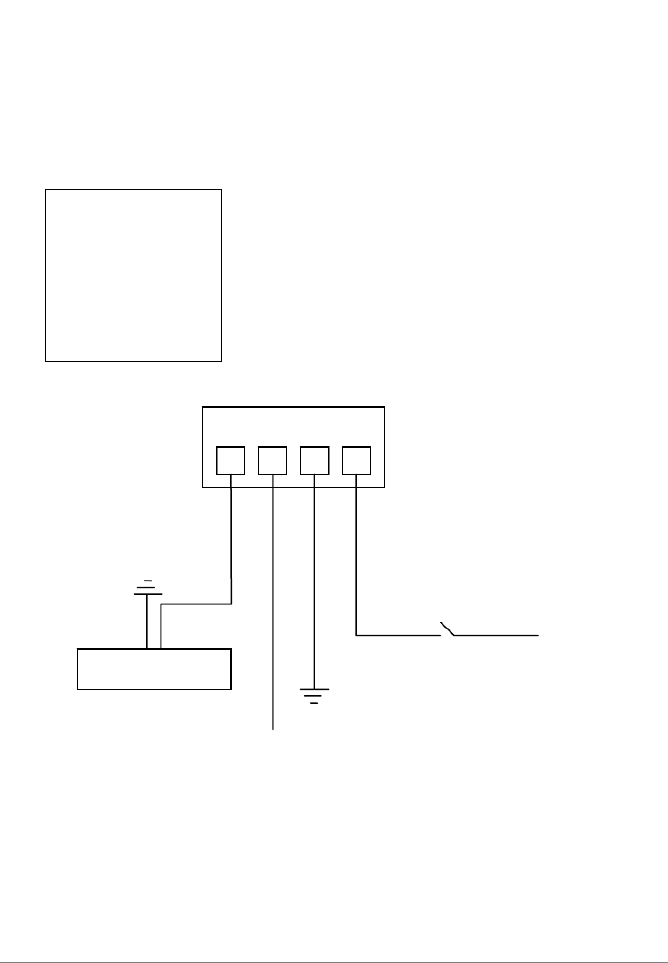
3.2 Digital I/O Terminal Block Connector
The Network Camera and Network Video Server, with the exception of the
NSC15 models, are equipped with a digital I/O interface. It can be used to
connect external alarm sensors (pins 1 and 2) or to power external devices
(pins 3 and 4).
From left to right: Pins 1 (DI+), 2 (DI-), 3 (Com) and 4 (No)
DI+: Digital Input (+), DI-: Digital Input GND (-)
Com: Power DC 12 V (+), No: Power GND (-)
The NVS30 Network Video Server features two additional pins 5 (+) and 6 (-)
that are used to connect analog CCTV camera with PTZ control (RS-485).
Ground
Ground
12 V
Alarm out device
12 V
Max. 30 W
Switch
NO COM DI- DI+

- 22 -
3.3 Package Contents
You should find the following items in the packaging of your INTELLINET
NETWORK SOLUTIONS video surveillance product.
1. Network Camera (or Network Video Server)
2. User manual (this document) and Quick Installation Guide
3. Installation CD
-> User Manual in electronic form in different languages
-> IP Installer Utility
-> Multi-Channel IP Surveillance Utility
4. Camera stand (all indoor NSCxx and NFCxx models)
5. Wall-Mount bracket (all outdoor NBCxx models)
6. Mounting hardware (NFSxx and NBCxx models)
7. Power adapter (except for NBC30 (550932))
-> Input: 110/230 V, 50/60 Hz
-> Output: - 5 V DC (NSC15 models)
- 12 V DC (other models)
If any items are missing, contact your dealer.

- 23 -
4: Installation
4.1 Connecting to the Camera
Connect the RJ45 network cable from the camera’s LAN port to your network;
e.g., the router or a LAN switch, then power on the camera. The boot sequence
will take about one minute. You will need to use the camera’s power adapter,
unless your camera supports PoE (see section 1.3 Model Overview). In that
case you can connect the RJ45 cable to a PoE enabled switch or injector to
power the camera.
By default, the network camera (or video server) searches for a DHCP server
on the network and obtains an IP address automatically. A very common DHCP
server is a router, a device that is found on most networks.
The presence of a DHCP server on your network simplifies the installation and
users with limited knowledge of TCP/IP networks can install the network
camera in minutes. If no DHCP server is found, the network camera will revert
to its default IP address 192.168.1.221.
On Windows systems, you want to use the IP Installer utility that finds the
camera on the network and lets you make changes to the configuration.
Once the camera is set up properly, it can be accessed with the computer’s
Web browser. The following sections describe the procedure for Windows,
MacOS and Linux users.

- 24 -
4.1.1 Windows XP, Vista and Windows 7
Insert the Installation CD into the CD or DVD-Drive.
After a few moments, the CD will automatically start
and display the screen below. If that does not happen,
you need to browse the CD with Windows Explorer and
double-click the autorun.exe file.
1. User Manuals
The user manual for the INTELLINET NETWORK SOLUTIONS Network
Camera is available in electronic form on the installation CD, along with
user manuals in different languages.
If you encounter differences between the screen shots shown in the user
manual and the actual screen contents, it is recommended that you open
the manual from the CD, as it may be a newer edition than the printed
version.
2. IP Installer for Windows
This utility is designed to find the network camera on your network and lets
you make changes to the configuration.
3. Video Surveillance Software
Refer to Chapter 6 Video Surveillance Software.

- 25 -
IP Installer for Windows Installation
Before you start with the installation, make sure that you are connected to
your computer with a user account that has administrator rights. The
screen shots below are taken from an installation on a Windows XP system.
The procedure on Vista and Windows 7 systems is similar.
To begin the installation, click on the link “IP Installer for Windows.” After
that, depending on your system’s settings, you may see the message
shown below.
Click on “Run” to continue …
… and click on “Yes” to begin the installation.
Select your preferred installation language, and then click on “Next.”
Click on “Next” on the following screen as well.

- 26 -
Specify the location where the program should be installed. The default path is
OK to be used on most systems. Click on “Browse…” to select a different
location and click on “Next” to continue.
Select the Windows Start Menu folder.
Select or de-select the optional Xvid Codec and MSN Plugin. If you are not sure
about these options, it is recommended to keep them selected.
Click “Next” to continue.

- 27 -
Verify the installation summary and click “Install” to begin the installation.
Once the installation has completed, click on “Finish”.
A new shortcut has been created on your computer
desktop; Double-click it to start the application.

- 28 -
IP Installer for Windows
When the program starts, you are presented with the screen shown below.
Depending on your camera model, the screen may look slightly different, but
the functionality is the same. The IP Installer utility lists all cameras that can be
found on your network. With this utility you can make changes to the
configuration, perform a firmware upgrade, restore the camera to factory
default values, and reboot the camera. Note: It may take up to three minutes
for IP Installer to show a camera that has been recently (re-)started.
The application has three main tabs: Camera, User and About.
Camera tab
UPnP device list: All cameras that are found on the network are displayed on
this tab. Cameras that are shown in red are currently
configured for a different network and cannot be accessed
with the Web browser before the IP settings of the camera
have been adjusted to your network (see Setup).
Search: The Search button can be used to refresh the view. Typically
it is not required to push the button, as the utility starts
scanning the network as soon as it is started.
Link to IE: Select the camera from the list and click this button to open
the camera with MS Internet Explorer. Note: This function
does not work for other Web browsers; however, you can
open the browser manually and open the URL
http://camera_ip_as_shown_in_list (in the example above,
you would open http://192.168.0.102).

- 29 -
Setup: Select a camera from the list and click the Setup button in
order to open the camera configuration dialog.
Upgrade: Select a camera from the list and click the Upgrade button if
you wish to upgrade the rmware of the camera. The
firmware upgrade can also be performed with your Web
browser.
Factory default: If you want to reset the camera settings to factory default
values, you can select a camera from the device list and click
this button. When you do this, you will be asked to enter the
administrator user name and password:
Enter “admin” for both.
You will then see the following message:
Click Yes to perform the factory reset.
Reboot: This function lets you reboot the camera. The procedure is
identical to the factory default function, except the camera
does not lose the settings.
Camera Tab – Setup Function
When you click on the Setup button, you first need to enter a valid
administrator user name and password (see above). You will then be presented
with the first page of the Setup menu. The first page shows some basic
information about the camera.
Click the Next button to open the next page.

- 30 -
User Account Settings Page
User Name: Enter the user name you wish to use for the new account.
Password: Enter the password for the new user account.
Confirm: Type the password in again.
Mode: There are three possible values to choose from:
1. Admin: User has full access to all camera functions.
2. Operator: User can view the live image and change image
related settings such as brightness, contrast, etc.
3. Viewer: User can view the live video of the camera, but is
unable to make any changes to the configuration.
Viewer
Authentication: On: Every user that connects to the camera has to enter a
valid user name and password.
Off: A user name and password is only required if the user
wants to change camera-related settings. By setting the
Viewer authentication to off, you allow any user to view the
camera’s live image.
Click the Next button to open the next conguration page.

- 31 -
Date/Time Settings Page
The network camera is equipped with an internal clock. You can display the
current date and time information on the video, so that when you look at
recorded video material or images you can easily tell when the recording was
made. Before you can use this function, you need to define how the camera
obtains the time.
Current Setting: Displays the current date and time.
PC clock: Displays the time of the PC that you are using right now.
Adjust: Keep current setting – no changes are made.
Synchronize with PC – instructs the camera to retrieve the
current date and time from the PC.
Manual setting - allows you to set up the date and time
yourself.
Synchronize with NTP – The camera will obtain the time from
an NTP server. Normally it is not required to change the NTP
server, as the default server “pool.ntp.org” is always
available. You can, however, manually overwrite the NTP
server by un-checking the option “auto.”
Interval: Define how often the camera should re-synchronize
the time with the NTP server’s time.
Time Zone: Select the correct time zone for the camera to display the
correct date and time.
Click the Next button to open the next conguration page.

- 32 -
Network Settings Page
The default configuration is shown above, and for most users there should be
no need to change these settings. Advanced users can change the following
values:
HTTP Port: This is the Web server port of the camera. The default value
is 80. You can change the value from 80 to a value between
1024 and 65535. Note that when you change the HTTP port,
you need to append the new port to the address of the
camera; e.g., http://192.168.0.102:1024.
IP Address: By default the camera obtains the IP address from a DHCP
server in the network. You can set up the camera with a static
IP address as well by activating the option “Use the following
IP.” If you are not familiar with IP addresses in general or the
IP address setup of your network, you should contact your
network administrator for the correct values.
DNS Setting: A DNS Server (DNS stands for Domain Name System) allows
the camera to contact an e-mail, FTP or NTP server using its
proper domain name (e.g., mail.mydomain.com) rather than
its IP address. If you set up the camera with a static IP
address, chances are that you will need to provide the DNS
server settings yourself as well.
Click the Next button to open the next conguration page.

- 33 -
PPPoE Settings Page
This page allows defining of the PPPoE settings of the camera. This function is
not required for the vast majority of users, and if you are not planning on
connecting the camera directly to a DSL modem (no network present, just the
camera connects directly to the modem) you can safely skip this page.
PPPoE is a common connection method for ADSL Internet services. It is not
required for cable modem service, or newer DSL services that operate with
dynamic IP addresses.
PPPoE connections require a user ID and password that are typically provided
by your ISP (Internet Service Provider). If there is no router in your network,
and you connect the camera straight to the DSL modem, you need to enter the
user ID and password here, so that the camera can connect to the Internet.
Note: The camera does not support idle timeout, meaning, it stays connected
to the Internet indefinitely. Users of time- or volume-based Internet services
need to be aware of this as the camera can cause significant usage charges for
the service. It is always a better option to have the router handle the PPPoE
connection to the Internet Service Provider, instead of the camera.
Click the Next button to open the next conguration page.

- 34 -
DDNS Settings Page
DDNS stands for “Dynamic DNS.” DDNS is useful for all users who have an
Internet service with a dynamic IP address. Most DSL services utilize IP
addresses that are highly dynamic and change as often as once every 24 hours.
Cable modem services typically keep the IP address assigned to a user for a
longer period of time; e.g., up to 30 days. In any case, after a certain amount
of time the IP address of your network will change unless you have a more
business-type Internet service that provides a permanent, static IP address.
Why does it matter if the IP address that the ISP assigns to you changes? If
you never want to access the camera remotely over the Internet, it wouldn’t
and you can skip this section.
If you want to connect to your camera from outside your network, the changing
IP addresses will make this task very complicated, as you never know under
which IP address you can reach your camera. DDNS is the solution to the
problem. Services like DYNDNS.ORG allow signing up for a free account and
setting up domain names like “mycamera.dyndns.org.” The DDNS service
assigns the current IP address that your ISP has assigned to you to the domain
name you have set up, so that you can always reach your camera at
http://mycamera.dyndns.org (example).
Note: We recommend using the DDNS client that is integrated in your router for
the DDNS service instead of the camera’s DDNS client.
The network camera supports three DDNS providers:
DYNDNS.ORG, DHS.ORG and TZO.ORG. Only DYNDNS.ORG is free (as of
February 2010).
Server name: Select the service (e.g., DYNDNS.ORG)
User ID: Enter your DDNS user account password here.
Password: Enter the password of your DDNS account here.
Confirm: Repeat the DDNS account password here.
Hostname: Enter the dynamic host name (e.g., “mycamera.dynsns.org”
here. Do not enter http://
Click the Next button to open the next conguration page.

- 36 -
Apply Settings Page
This is the last page of the Setup.
All configuration changes you have made on the previous screens will be saved
when you click the Apply button. If you have selected an additional language to
be installed on the previous page, clicking Apply will install that language as
well.
After you click Apply, the main screen of IP Installer shows up, and after a
period of 60 to 180 seconds, the camera will show up in the UPnP device list.
You may need to click the Search button to get the camera to show up again.
Camera tab – Upgrade function
The firmware is basically the operating system of the camera. New functions
are introduced from time to time, and compatibility patches and fixes are
released to make your INTELLINET camera an even better product. A firmware
upgrade replaces the internal camera software with a new version.
Note: A failed firmware upgrade can render your camera inoperable.
Before you start with the firmware upgrade, ask yourself a few questions:
1. Has Technical Support instructed me to upgrade, or is my camera operating
erratically or do certain functions in the camera not work as they should?
2. Am I absolutely sure that I downloaded the correct firmware file for my
camera from the INTELLINET NETWORK SOLUTIONS Web site?
3. Can I be reasonably certain that the power will not go out during the next 10
minutes?
4. Are all unnecessary programs on my computer closed?

- 37 -
5. Will the battery in my notebook last for at least another 10 minutes?
6. Am I connected to the camera with an RJ45 cable (not wireless)?
7. Is the camera I want to upgrade located in my local network?
8. Am I sure about what I am doing?
If you answer any of these questions with “no,” you should not perform the
firmware upgrade and skip this section.
Select a network camera from the UPnP device list and click on Upgrade to
upgrade the firmware. As before, you have to key in the user name and
password of the administrator to enter the upgrade page. You will then see the
following screen:
Click on Browse and select the correct firmware file. The file must have the file
extension “.bin.” Click on Open to return to the firmware upgrade page. The
Upgrade button that was previously grayed out is now available.
Click the Upgrade button to begin the upgrade process. The upgrade takes
place in several stages. The screen informs you about the progress. At the end
of the upgrade the status indicates “Rebooting” while the progress bar moves
from 0 to 100%.
Note: Do not leave this screen and do not close the program yet. Wait for the
status to display “Done” and when it does, click on “Previous” to go back to the
main screen. As before, it may take up to three minutes for the camera to re-
appear.

- 38 -
User tab
This screen offers two functions:
1. You can change the individual settings of the camera in a similar fashion as
with the Setup function on the main screen. However, instead of clicking on
Previous and Next to switch between the screens, you can access the individual
options more quickly by clicking on any of the tabs (User, Date/Time, TCP/IP,
PPPoE and DDNS). You cannot install additional languages with this function,
however.
2. You can load the camera configuration into the IP Installer utility, and then
save it to your computer hard drive. This can be useful if you wish to create a
backup of the entire configuration in case you want to reload it at a later time.
You can also use this function to load a configuration previously saved on the
PC and load it back into the camera configuration.
To begin, select either “From PC File” or “From Device,” then click Load.
If you select “From PC File” you will be asked to specify the configuration file on
your computer hard drive.
If you select “From Device” a screen opens up that asks you to select the
camera and enter the administrator user name and password.
Once completed, the screen shows the configuration data, and you can make
changes to the settings as you see fit. When you are ready to submit the
settings to the camera, click on Apply. Select the camera from the device list,
enter the administrator user name and password and click OK. The camera
settings are now saved into the camera configuration.
If you want to create another backup of the configuration, click on Save and
enter a proper filename, such as “camera_1_config.conf,” before you click
Save.

- 41 -
4.1.2 MacOS
The installation on Apple systems running MacOS X does not involve the
INTELLINET installation CD. The INTELLINET NETWORK SOLUTIONS network
camera supports Apple’s Bonjour service.
Bonjour, formerly Rendezvous, is Apple Inc.'s
trade name for its implementation of Zeroconf, a
service discovery protocol. Bonjour locates
devices such as printers or network cameras, as
well as other computers, and the services that
those devices offer on a local network using
multicast Domain Name System service records.
The software is built into Apple's Mac OS X
operating system from version 10.2 onward.
1. Open the Safari Web browser and open the Bookmarks toolbar, where you
will find the Bonjour link.
Screen shot shown of Safari 4.x.

- 42 -
The Network Camera is shown in the category Webpages. In order to connect
to the camera, double-click the circled link. Safari then connects to the camera
and the message below appears:
Click on Allow and you will see the camera live image a few moments later.
Refer to Chapter 5 for explanations on the Web interface options of your
network camera.

- 43 -
4.1.3 Linux
The installation on Linux systems does not require any
special software. The network camera is compatible to
Web browsers such as Firefox and Konqueror.
The initial installation requires the setup of the
camera’s IP address. As the camera by default obtains
an IP address from a DHCP server in the network (e.g.,
a router), you can access the camera as soon as you
have obtained the IP address from the router’s DHCP
client log. Alternatively, you may use Bonjour
(mDNSResponder), which is also available for Linux.
If no DHCP server is connected to your network, the camera reverts to its
default IP address 192.168.1.221. In order to gain access to the camera, you
need to change the IP settings of your system manually. Set up the IP address
to be in range of 192.168.1.xxx (where xxx is not 221). Then open your Web
browser and connect to address http://192.168.1.221. Log in to the camera
and click on the Settings link to open the administrator menu. Refer to section
5.2 Settings Page for more details.

- 44 -
5: Web Browser Interface
5.1 Live Video Page
(1): This link opens the Settings page of the network camera.
This is the administrator area that only users with admin
user rights have access to. Refer to Chapter 5.2 for detailed
information on the administrator settings.
(2): In order to change any of the client settings, you need to have at least
operator user rights on the camera.
Click on this link to access the following functions:
Mode: Select the video format
(depending on model and settings, there
are up to three options to choose from:
H.264, MPEG4 and MJPEG)
Date/Time Stamp Snapshot/Full Screen
Audio Controls
Digital Zoom
Video Controls
(1)
(2)
(3)

- 45 -
View size: You can define the size of the live video by selecting the
value of your choice. Depending on the camera model and settings,
you may select values such as 320x240, 640x480, 2x, 1x, 1/2x, 1/4x.
Protocol: Select from any of these protocols: HTTP, TCP, UDP. The
default value is HTTP, and normally there is no reason to change it.
Video buffer: Turn the Video Buffer function On or Off. Enabling the
video buffer makes the video stream smoother in unsteady network
environments or over remote Internet connections. But activating the
buffer also means that there is a longer delay between real time and
when the events appear on your screen.
(3): The image setup allows control of the
image parameters shown on the right.
Depending on your camera model, these
options can vary. You can either move the
slider to adjust the value, or you can type
the value into the field.
Brightness: Higher values generate
brighter video and vice versa.
Contrast: Raise or lower the contrast of the video.
Sharpness: Crisper video can be generated if the sharpness is set to a
higher value.
Saturation: When set to “0,” the image becomes black and white.
Raise the value to increase the amount of color in the video.
Hue: Most sources of visible light contain energy over a band of
wavelengths. Hue is the wavelength within the visible-light spectrum
at which the energy output from a source is greatest. If you don’t
understand any of this, don’t worry. Normally there is no need to
change the default value.
Exposure (not shown): This optional parameter allows controlling the
exposure time which has a direct impact on the brightness of the
image. The smaller the value, the darker the image becomes. This
parameter is useful for cameras that are installed outdoors, or pointing
to the outside.

- 46 -
Digital Zoom:
The digital zoom function allows magnification of certain areas of the
video. After you click on the magnification icon, a window appears as
an overlay on top of the image. See below.
You can drag the box over the image, and you can adjust the
magnification by moving the slider toward “T” (tele-zoom) or “W”
(wide-angle). The more you move the slider toward “T,” the further
you zoom in and details appear larger. It is normal behavior that the
image quality is reduced when using the digital zoom function.
Digital Zoom is only available in MS Internet Explorer Web browsers.
Video Controls:
Use the Pause button to temporarily pause the live video. The last
frame remains on the screen until you click the Play button.
Use the Stop button to disconnect from the camera. The display turns
black until you click the Play button to reconnect again.
Click on the Record button, if you wish to record the live video to your
computer’s hard drive. When selected, a prompt will request you to
specify the folder in which you want to store the video. Click OK to
begin the recording. The Record button now turns red, indicating that
the recording is active. Click it again to stop the recording.

- 47 -
Snapshot:
Use this button to take a snapshot of the video. When you click the
button, a window opens showing the capture frame. You can then save
the image by clicking on the Save button.
Full Screen:
Click this button to view the video in full screen mode. In full screen
mode, the video is stretched to fit the entire screen and all control
graphics and window elements are no longer displayed. To return from
full screen mode, press the ESC key on your keyboard. You can also
right- or left-click any part of the image with your mouse.
Audio Controls:
Click on the Loudspeaker button and the camera will play audio,
captured by the camera’s integrated microphone. Use the slider to
adjust the volume.
If your computer or notebook is equipped with a microphone, and a
pair of active speakers is connected to the camera’s speaker output
ports, you can click on the Microphone button to send audio from your
computer over the network to the camera. The camera will then play
the audio back on the connected speakers. This can be a useful
function if you want to interact with people that are in close proximity
to the camera’s location.
- 48 -
5.2 Settings Page (Administrator Menu)
The camera’s administrator menu consists of two main
options.
Basic: The camera’s network, image and security settings are
configured here.
Advanced: Motion detection, event triggers, e-mail and FTP
uploads can be configured here.
5.2.1 Settings Page – Basic Settings
The basic link reveals the subsections “System,” “Camera,”
“Network” and “Security.”
System: The System section contains the subsections
“Information,” “Date/Time,” “Initialize” and, depending on
your camera model, “Language.” If you do not see the
“Language” option as shown on the right, you can find it as
part of the “Initialize” section.
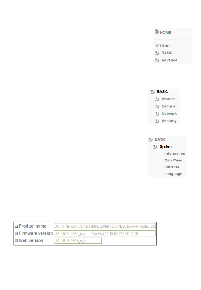
Information: The product name and firmware version of your camera are shown
on this page. If you ever need to contact Technical Support, make sure that
you include the information shown on this page in your communications.
Example:
Note: Web version is an optional piece of information that is not shown on all
camera models.

- 49 -
Date/Time: In order to display the date and time stamp on the live video, or to
utilize its scheduler, the camera is equipped with an internal time clock. There
are several ways to set up the camera time.
Note: Depending on your camera model and firmware version, the Daylight
Saving Time option may not be available.
Current date/time: Displays the camera’s current date/time.
PC clock: This is the date and time of the computer you are
currently using to connect to the camera.
Date/time format: The format determines how the date/time is displayed on
the live video. Select the format that suits you best.
Adjust: There are four options.
“Keep current setting” means that you don’t want to
change the date and time.
“Synchronize with PC” adjusts the camera time to the
time of your PC. Be aware of the fact that this option sets
the time only one time. From that point forward, the
camera time will start to differ from your PC time as time
progresses, and occasional re-synchronization will be
necessary.
“Manual setting” lets you manually enter the time and
date. As with the previous option, the camera’s time will

- 50 -
become inaccurate as time passes and you will need to
re-synchronize the time periodically.
“Synchronize with NTP”: This option is the recommended
setting. In this mode, the camera will synchronize its
time settings based on the interval setting (ranging from
once per hour to once per day). The camera obtains the
time from the NTP server (default: pool.ntp.org). You can
use the default value unless your camera is not
connected to the Internet, or if a firewall in your network
blocks the outgoing NTP request of the camera. Uncheck
the “Auto” setting and you can enter a different NTP
server; e.g., a server in your local network.
Time zone: Select the correct time zone for your location.
Daylight Saving Time (optional):
If your camera is equipped with this option, you can
define the range of Daylight Saving Time by activating
this option. The camera will adjust the time (move the
clock forward or backward by one hour) depending on
the programmed start and end time.
If your camera is not equipped with this feature, you can
adjust the time zone manually for Daylight Saving Time.
Initialize: This subcategory allows the performing of certain
maintenance tasks.
Reboot: Click the button to reboot the camera. This may be useful
if the camera performs poorly, or if you have made
changes to some of the camera’s network settings.
Factory default: Click to erase all settings and revert the camera back to
the factory default state.

- 51 -
Backup setting data: This function allows saving the current configuration of
the camera to a file on your computer’s hard drive.
Saving the configuration is useful in case you ever want
to reload a specific configuration; e.g., in order to set up
another camera of the same model and firmware version
with the exact same configuration. Since the IP address
configuration is also part of the setting date, you must be
careful not to restore the same settings to two or more
cameras when all of them are connected to the same
network. Otherwise, you would be creating an IP conflict
in your network.
Restore setting: With this function, you can reload a previously saved
configuration back into your camera. Click Browse to
locate the configuration file and OK to begin the process.
The camera will perform a reboot at the end of the
procedure and the new settings will become effective.
Firmware upgrade: From time to time, there will be a new firmware version
available for your camera. New firmware versions can
enhance the functionality of the camera, or they can fix
problems.
Before you begin, make sure that you have obtained a
proper firmware from the INTELLINET NETWORK
SOLUTIONS Web site. If you are not 100% sure about
this, do not proceed. Instead, contact the Technical
Support team to verify the firmware version.
Also, do not perform the upgrade from a computer that is
connected to the network wirelessly, as the connection is
inherently less stable than a cable-based connection.
If you have the correct firmware file, make sure that you
uncompress the ZIP file first (if the firmware file is an
archive) and you end up with a file that has an extension
*.bin. Click on Browse and select the *bin file. Click on
OK to begin the upgrade process. The following message
will appear:
Click OK to continue.

- 52 -
Another message will appear:
Click on Cancel to abort the operation. Click on OK to
start the upgrade process.
You will see the following messages:
Note: You may see additional messages at this stage.
When you see this message, the upgrade has been
completed. It may take up to two minutes to re-gain
access to the camera. If the camera no longer responds,
use the Windows IP Installer utility to find the camera
and re-configure the IP Address settings.
Language: You can replace the language in the user interface of your network
camera. On the Installation CD are different language files starting with “LNG_”
and ending with “.lang.” Click on Browse, select the language you wish to install
and then click on OK to begin the process.
Note: Some cameras display the language option under the Initialize link.
This concludes the Basic -> System settings.

- 53 -
Camera: This section contains the video-related settings of the camera.
Depending on the camera model, the options may vary. There are two different
styles, each of which has slightly different options. First you need to identify
which style applies to your camera.
Style 1:
The main options are:
- General
- MPEG4
- Computer View
- Mobile View
- MJPEG
Style 2:
The camera section contains the subsections
“General,” “H.264,” “MPEG4,” “MJPEG,” “3GPP,”
“Advance” and “Playback.”
This style applies to all H.264 1.3 Megapixel network
cameras.
The following pages explain each of the options and refer to either Style 1 or
Style 2. The options for style 1 are explained first.

- 54 -
Camera -> General (Style 1):
RTSP: RTSP stands for Real Time Streaming Protocol. RTSP is
supported by most media clients, such as Real Player, VLC
and QuickTime. If you only plan to view the camera video with
your Web browser or with one of the provided software
utilities, you do not need to activate this option. Note that
activating the RTSP option disables the camera’s ability to
send out Motion-JPEG video.
Image rotated: Choose from one of the following options: “None,” “Mirror,”
“Flip” and “Mirror + Flip.” With this function you can mirror
the image vertically, horizontally or both. The default value is
“None.”
Lighting: This is an important parameter. There are three values:
“50Hz,” “60Hz” and “Outdoor.”
If your camera is installed so that it’s facing outside, you
should select “Outdoor.” If your camera is installed indoors,
you must select the appropriate light frequency (either 50 or
60 Hz; e.g., in the US select 60 Hz, in Germany, Poland or
Italy select 50 Hz).
White Balance: This parameter controls how the camera interprets colors.
Depending on the previous selection (Lighting), you can
choose from the following values: “Auto,” “Fluorescent,”
“Incandescent,” “Sunny,” “Cloudy” or “Black & White.”
You should select the value that best represents the
environment the camera is installed in. You can also leave the
default value “Auto,” as it typically delivers very good results.

- 55 -
IR: Cameras that are equipped with infrared allow the control of
the camera’s function at night.
On: Activates the night vision mode. The IR cut filter is
removed when this option is enabled. The IR LEDs are
activated and the image turns black and white.
Off: The IR functionality is deactivated and the camera will
always send color images. At night, however, the camera will
not be able to capture proper video.
Auto: In this mode the camera automatically engages the
night vision mode when a certain level of light is reached. The
“Bright” value defines the threshold at which the camera
switches IR mode to color mode. The “Dark” value does the
opposite. It tells the camera at which light level to remove the
IR cut filter and activate the IR LEDs.
The image below illustrates the difference between the IR
mode being on and off.
Left: IR = “Off.” Right: IR = “On” or “Auto”
Note: Standard cameras do not display this parameter; they
display a parameter called night mode, which can be set to
“Auto” or “Off.” Auto means that the camera increases the
shutter time to ¼ second, creating a longer exposure time,
which allows the camera to capture images even in low light
conditions. When set to “Off,” the camera will not adjust the
shutter time and the resulting images are darker.
Overlay: Activate text overlay in
order to display the date
and time information on
the live image of the
camera, along with an
alias name for the camera.
When these options are
activated, the live video
shows the information in
the specified position, as
shown to the right.

- 56 -
When privacy masking is activated, a new option appears on
the screen that allows you to censor (black out) an area in the
image you don’t wish the camera to capture.
Use your mouse in order to resize the box and move it into
the desired position on the live video. Privacy masking is an
important function designed to protect the people’s right for
privacy.
Example 1: The camera is installed in your home: e.g.,
overlooking your driveway. In the background is the
neighbor’s house, which you have no intention of monitoring.
It would illegal in some cases for you to do so. To resolve this
problem, you can activate a privacy zone over your neighbor’s
house.
Example 2: The camera is installed in your company; for
example, overlooking the warehouse. In one corner of the
warehouse is the break room, where the employees go for
their lunch breaks. In many countries it is not permitted to
monitor the workers during their break. To comply with laws
and regulations, you can dene a privacy mask in the break
area to ensure that this area is not being monitored or
recorded by the camera.
Note: Privacy masking can only be set up when using MS
Internet Explorer.
Text overlay is only applied to the MJPEG video stream, if
RTSP mode is set to off.

- 57 -
Camera -> MPEG4 -> Computer View (Style 1):
The RTSP and RTP options are for advanced users only. If you are not familiar
with any of these terms, including Multicast and Unicast, there is a good chance
that you do not need these functions of the camera.
RTSP: This is only shown if the RTSP mode is enabled in the general
settings. When activated, you can define which port you wish
to use for the RTSP protocol. The standard port is 554, but
you can use a different port, if desired.
The viewer authentication controls whether or not a valid user
name and password are required in order to access the
camera live image. For security reasons it is recommended to
set this value to “On” (unlike in the screen shot above);
otherwise anyone who knows the network address of your
camera can potentially access the video stream.
RTP: The Real-time Transport Protocol (RTP) defines a standardized
packet format for delivering audio and video over the
Internet. This option is only shown if the RTSP mode is
enabled in the general settings.
Unicast Streaming: Define the port range for standard Unicast
streaming here.
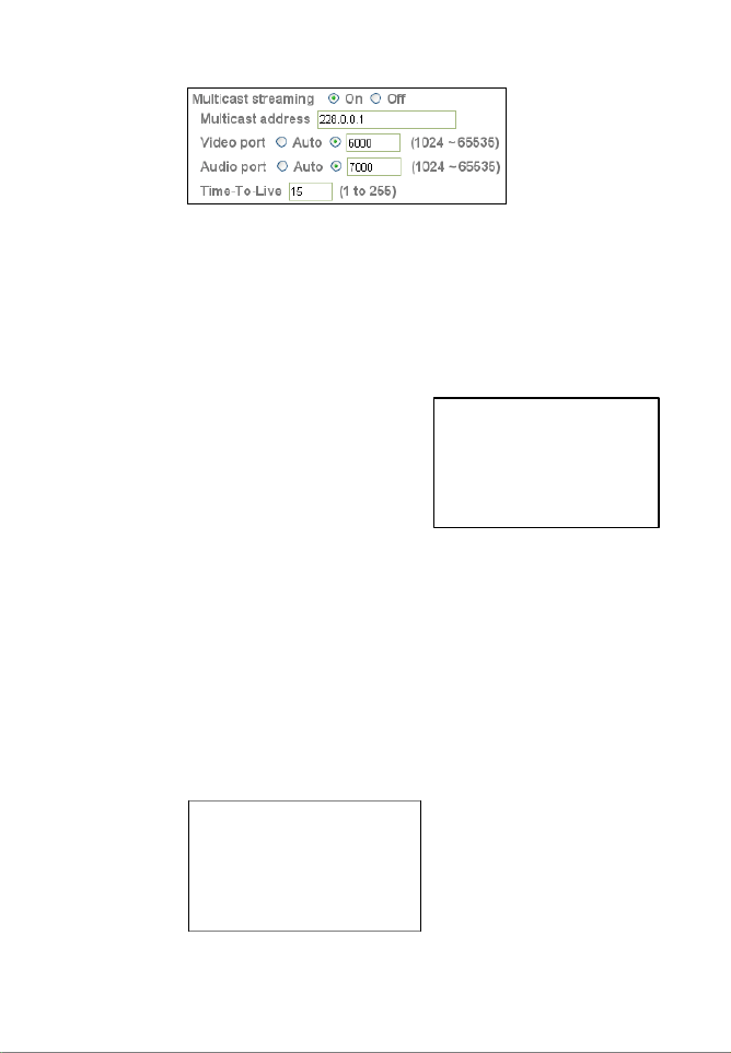
Multicast Streaming: Set to “On” to enable it.
Note: If the camera has firmware 1.6.16.05 or newer installed, the RTSP and
RTP options can be found on the Camera -> General page.
- 58 -
Once you activate the multicast option, the screen will show
additional options:
Enter the address of your multicast server along with the
audio and video port. The Time-To-Live value defines how
long multicast traffic will expand across routers. Routers have
a TTL threshold assigned and only datagrams with a TTL
greater than the interface's threshold are forwarded.
Below are additional details regarding the differences between
Unicast and Multicast.
Unicast: For each connected
computer there is a separate
TCP/IP connection. When 20
computers are connected to
the camera, the camera has
to create 20 different
connections, and the camera
has to send out the same
video data to each of the 20 computers. This not only puts a
significant load on the camera, it also creates massive
amounts of data that need to be transferred over the network
to each connected client.
Unicast is still the most common model when using a network
camera, since most times only a recording device (DVR or
NVR) is connected to the camera and perhaps connections
from just a small number of computers.
Multicast: Here the initial stream is sent to the router only,
which creates optimal distribution paths for datagrams sent to
a multicast destination address. Whether one or 300 PCs are
connected to the video stream
does not matter. The
bandwidth and load of the
local camera is unaffected.
Because of this, multicast is
the preferred choice for
broadcast-type applications.

- 59 -
MPEG4 Viewer Port:
The camera uses two ports, one for regular connections and
one for SSL (HTTPS) encrypted connections. If you are using
the INTELLINET NETWORK SOLUTIONS network camera only
in your local network and do not wish to access the video
remotely over an Internet connection, these values are
unimportant. For remote connections, however, they are
important. The ports entered here need to be programmed
into your router’s port forwarding table to allow incoming
remote connections. Refer to Chapter 7 Remote Access and
Router Setup for details on the port forwarding setup.
Image Size: Define the video resolution that the camera sends out by
selecting the appropriate resolution (160x120, 320x240 and
640x480 pixels) here. The image size has a direct impact on
the amount of network bandwidth required in order to submit
the video stream over the network. The higher the resolution,
the more network bandwidth is used to deliver the video
stream.
Frame rate: Select from a range of 5 to 30 fps to define the maximum
frame rate (frames per second) of the video. The higher the
frame rate, the smoother the video and the more network
bandwidth required to deliver the video stream.
Quality: You can control the image quality of the video by selecting
“Fixed Quality” and defining the image quality by selecting
one of the following values “Medium,” “Standard,” “Good,”
“Detailed” and “Excellent.” Or you can choose to specify the
bit rate of the video the camera must not exceed. When you
set the quality to “Auto,” the camera varies the image quality
automatically based on the connection speed of the connected
client.

- 60 -
Camera -> MPEG4 -> Mobile View (Style 1):
The network camera has the ability to
send out a low-resolution video stream
that is ideal for remote viewing via a
mobile phone.
The camera supports 3GPP and 2.5
WAP for older phones.
The options are the same as the
computer view, except that the image
size is fixed to 160x120 pixels, and the
frame rate and quality settings are
much lower.
Camera -> MJPEG (Style 1):
In addition to MPEG4, the network camera can also send out a Motion-JPEG
video stream. While Motion-JPEG has a much larger network footprint than
MPEG4 or H.264, and therefore requires more network bandwidth to submit the
same video information, it is still widely used in the video surveillance
environment. As seen before, you can define the individual ports that the video
stream uses, along with the image size, frame rate and quality.
Note: When RTSP is activated, Motion-JPEG cannot be used at the same time
and the screen options are disabled.
This concludes the camera category options for all MPEG4/Motion-JPEG network
cameras. The following section describes the options for the H.264 Megapixel
camera models.

- 61 -
Camera -> General (Style 2):
RTSP: Specify the RTSP port here. The default port is 554.
RTP: Define the RTP port range here.
Image Rotated: Choose from one of the following options: “None,” “Mirror,”
“Flip” and “Mirror + Flip.” With this function you can mirror
the image vertically, horizontally or both. The default value is
“None.”
Audio Codec: Here you can define which audio codec the camera uses.
There are four choices:
g.711 u-law / g.711 a-law: G.711, also known as Pulse Code
Modulation (PCM), is a very commonly used waveform codec
that generates a 64 kbps bit rate.
AMR Audio: AMR was adopted as the standard speech codec
by 3GPP in October 1998 and is now widely used in GSM and
UMTS. AMR Audio uses less bandwidth than g.711 audio.
When AMR is selected, you can specify the bit rate between
4.75 and 12.2 Kbps.
Off: Disable the audio function in the camera.
Audio mode: There are two choices here. “Full Duplex” means that the
camera can send and receive audio simultaneously. “Half
Duplex” means the camera can send out audio to the
connected client PC, but can’t receive audio from it.

- 62 -
Video Clip Format:
The camera has the ability to send out short video clips to an
FTP server, via e-mail or to a local SMB network storage
device. Find more about that in the advanced section. Here
you define the format of the video clip. You can choose
between H.264 and MPEG4. Each of these streams can be
defined individually in terms of video resolution and quality in
the corresponding menus.
IR Threshold: If your camera is equipped with Infrared, you can define the
behavior of the camera under different light conditions.
On: Activates night vision permanently. The camera removes
the IR cut filter and activates the IR LEDs. The resulting
image is black and white, but the camera can capture video
even in complete darkness.
Off: Permanently deactivates the night vision mode. Even at
night or under poor light conditions the camera will continue
to send color video. The disadvantage is that the video may
not contain any visual details due to the low light levels.
Auto: The camera automatically activates the night vision
mode based on the Bright and Dark parameters.
The “Bright” value defines the threshold at which the camera
switches from IR mode to color mode.
The “Dark” value does the opposite. It tells the camera at
which light level to remove the IR cut filter and activate the IR
LEDs.
The Bright parameter defines the time when the camera goes
into color mode in the morning while the Dark parameter tells
the camera when to engage the night vision mode at night.
Overlay: You can activate a text overlay on the live image. This can be
either a date and time stamp along with the camera’s alias, or
it can be a privacy mask. Refer to the overlay section in style
1 for more detailed information on the setup.
Note: The text overlay is only active for H.264 and MPEG4 video.

- 65 -
Camera -> Advance (Style 2):
White Balance: Select the value that best represents the installation
environment of the camera, or leave it on auto to let the
camera do the adjustment automatically for you.
Lighting: If the camera is installed indoors, select either 50 or 60 Hz,
depending on the power grid frequency in your country.
Select Outdoor, if the camera is installed outside, or pointing
outside. The automatic mode can also be used, but best
results are ensured by manually specifying the correct value
for your location.
Exposure mode: Exposure mode controls the behavior of the shutter, which is
used to control the brightness of the video.
Auto: The camera controls the shutter speed automatically.
As light levels decrease, the camera keeps the shutter open
longer and vice versa.
Auto (fast shutter): This mode provides better results when
moving objects (e.g., cars) are captured by the camera. The
shorter shutter time ensures that the moving object remains
sharp.
Manual: When this is selected, you can manually specify the
time the camera keeps the shutter open. This is useful if you
want to instruct the camera to keep the shutter open for a
relatively long time in order to be able to capture video in
poor light conditions. Values range from ¼ sec. to 1/120
seconds. With the gain value you can also adjust the
exposure time. This feature is not suitable if the camera
captures outdoor video and typically, you do not need to
change the exposure mode to manual.

- 66 -
Camera -> Playback (Style 2):
The INTELLINET NETWORK SOLUTIONS Network Camera is equipped with an
integrated video player. With this player you can play back videos that you
have recorded with the camera; e.g., by using the record function on the live
video page. The video player can also playback other video sources, if the
necessary video codecs are installed on your computer.
The controls consist of the typical array of buttons you find in most common
media players; e.g., play, pause, stop and open, fast forward and rewind, time
display, volume and full screen controls.
Note: The video player can only be used with MS Internet Explorer. Other Web
browsers do not support this function.

- 67 -
Camera -> Network -> Information:
On this page you can define the network settings of the camera. By default the
camera is set up to automatically obtain the necessary IP information from the
DHCP server (e.g., the router) in your network. You can, however, set up the IP
address and related settings manually.
MAC address: MAC address stands for Media Access Control address. This is
the unique hardware address of the camera’s network
interface.
Obtain an IP address automatically (DHCP): This is the default setting. In this
mode the camera obtains the IP information from the DHCP
server in your network.
Use the following IP address: Activate this option in order to assign a static IP
address to the camera. You need to enter a valid IP address,
subnet mask and default gateway address in the
corresponding fields.
Use the following DNS server address: When you disable DHCP, you also need
to provide the camera with valid DNS settings. The Primary
DNS server must be filled out. It is often the same IP address
as the Gateway address.
HTTP port number: The default value is 80 and normally there is no need to
change it. If you decide to change the http port to a different
value; e.g., 1024, you need to do two things:
1. After saving the settings you need to reboot the camera via
the System -> Initialize menu.
2. After the reboot is completed you need to connect to the
camera using the URL http://camera_ip:portnumber.
Produkt Specifikationer
| Mærke: | Intellinet |
| Kategori: | Overvågningskamera |
| Model: | NFC31-IR |
Har du brug for hjælp?
Hvis du har brug for hjælp til Intellinet NFC31-IR stil et spørgsmål nedenfor, og andre brugere vil svare dig
Overvågningskamera Intellinet Manualer

21 August 2024
21 August 2024
20 August 2024
20 August 2024
20 August 2024
20 August 2024
20 August 2024
20 August 2024
19 August 2024
19 August 2024
Overvågningskamera Manualer
- Overvågningskamera Bosch
- Overvågningskamera Denver
- Overvågningskamera Sony
- Overvågningskamera Canon
- Overvågningskamera Netis
- Overvågningskamera Samsung
- Overvågningskamera Panasonic
- Overvågningskamera Extech
- Overvågningskamera Moog
- Overvågningskamera TP-Link
- Overvågningskamera Philips
- Overvågningskamera Vitek
- Overvågningskamera Gigaset
- Overvågningskamera Pioneer
- Overvågningskamera Mitsubishi
- Overvågningskamera Braun
- Overvågningskamera Logitech
- Overvågningskamera Emos
- Overvågningskamera Google
- Overvågningskamera Technaxx
- Overvågningskamera HP
- Overvågningskamera Waeco
- Overvågningskamera Garmin
- Overvågningskamera Sanyo
- Overvågningskamera Grundig
- Overvågningskamera D-Link
- Overvågningskamera Arlo
- Overvågningskamera Motorola
- Overvågningskamera Asus
- Overvågningskamera Toshiba
- Overvågningskamera Pyle
- Overvågningskamera Kodak
- Overvågningskamera Furrion
- Overvågningskamera InFocus
- Overvågningskamera Nedis
- Overvågningskamera Friedland
- Overvågningskamera Abus
- Overvågningskamera Planet
- Overvågningskamera Adj
- Overvågningskamera Hama
- Overvågningskamera Creative
- Overvågningskamera Thomson
- Overvågningskamera Belkin
- Overvågningskamera Edimax
- Overvågningskamera Burg Wächter
- Overvågningskamera Clas Ohlson
- Overvågningskamera DataVideo
- Overvågningskamera Strong
- Overvågningskamera TRENDnet
- Overvågningskamera Smartwares
- Overvågningskamera Trevi
- Overvågningskamera Trust
- Overvågningskamera Laserliner
- Overvågningskamera Blaupunkt
- Overvågningskamera JVC
- Overvågningskamera Honeywell
- Overvågningskamera Uniden
- Overvågningskamera Buffalo
- Overvågningskamera Linksys
- Overvågningskamera Megasat
- Overvågningskamera Cisco
- Overvågningskamera EZVIZ
- Overvågningskamera König
- Overvågningskamera Elro
- Overvågningskamera Gembird
- Overvågningskamera Powerfix
- Overvågningskamera Alpine
- Overvågningskamera Netgear
- Overvågningskamera Maginon
- Overvågningskamera Yale
- Overvågningskamera Withings
- Overvågningskamera Nest
- Overvågningskamera Kerbl
- Overvågningskamera Vtech
- Overvågningskamera Exibel
- Overvågningskamera Genie
- Overvågningskamera Vaddio
- Overvågningskamera Bresser
- Overvågningskamera Western Digital
- Overvågningskamera Anker
- Overvågningskamera Digitus
- Overvågningskamera Zebra
- Overvågningskamera Jensen
- Overvågningskamera Alecto
- Overvågningskamera Flamingo
- Overvågningskamera Rollei
- Overvågningskamera Olympia
- Overvågningskamera Xiaomi
- Overvågningskamera Niceboy
- Overvågningskamera Aiptek
- Overvågningskamera Schneider
- Overvågningskamera B/R/K
- Overvågningskamera Marmitek
- Overvågningskamera Tesla
- Overvågningskamera Imou
- Overvågningskamera Ricoh
- Overvågningskamera Nexxt
- Overvågningskamera Aida
- Overvågningskamera APC
- Overvågningskamera Foscam
- Overvågningskamera Lorex
- Overvågningskamera Ikan
- Overvågningskamera Velleman
- Overvågningskamera LevelOne
- Overvågningskamera Marshall
- Overvågningskamera FLIR
- Overvågningskamera Perel
- Overvågningskamera Swann
- Overvågningskamera Vivotek
- Overvågningskamera Joblotron
- Overvågningskamera JUNG
- Overvågningskamera ORNO
- Overvågningskamera Binatone
- Overvågningskamera ZyXEL
- Overvågningskamera Fortinet
- Overvågningskamera Netatmo
- Overvågningskamera Tenda
- Overvågningskamera Eufy
- Overvågningskamera Ring
- Overvågningskamera M-e
- Overvågningskamera Overmax
- Overvågningskamera Somfy
- Overvågningskamera Y-cam
- Overvågningskamera Hikvision
- Overvågningskamera Monacor
- Overvågningskamera ION
- Overvågningskamera Raymarine
- Overvågningskamera Ubiquiti Networks
- Overvågningskamera AVerMedia
- Overvågningskamera EnGenius
- Overvågningskamera Reolink
- Overvågningskamera Grandstream
- Overvågningskamera Trebs
- Overvågningskamera EVE
- Overvågningskamera Renkforce
- Overvågningskamera Marshall Electronics
- Overvågningskamera Manhattan
- Overvågningskamera SPC
- Overvågningskamera Caliber
- Overvågningskamera Pentatech
- Overvågningskamera Switel
- Overvågningskamera AVtech
- Overvågningskamera LogiLink
- Overvågningskamera Orion
- Overvågningskamera Eminent
- Overvågningskamera Kramer
- Overvågningskamera QSC
- Overvågningskamera Hanwha
- Overvågningskamera Brilliant
- Overvågningskamera Lanberg
- Overvågningskamera Hive
- Overvågningskamera Siedle
- Overvågningskamera BirdDog
- Overvågningskamera Evolveo
- Overvågningskamera Genius
- Overvågningskamera KJB Security Products
- Overvågningskamera Valueline
- Overvågningskamera Provision-ISR
- Overvågningskamera Quantum
- Overvågningskamera Axis
- Overvågningskamera ACTi
- Overvågningskamera CRUX
- Overvågningskamera Avanti
- Overvågningskamera Vimar
- Overvågningskamera Aluratek
- Overvågningskamera Dahua Technology
- Overvågningskamera Chacon
- Overvågningskamera SereneLife
- Overvågningskamera ZKTeco
- Overvågningskamera AG Neovo
- Overvågningskamera Stabo
- Overvågningskamera EtiamPro
- Overvågningskamera First Alert
- Overvågningskamera Speco Technologies
- Overvågningskamera Boss
- Overvågningskamera Broan
- Overvågningskamera Conceptronic
- Overvågningskamera Avidsen
- Overvågningskamera Crestron
- Overvågningskamera Lindy
- Overvågningskamera Kogan
- Overvågningskamera AVMATRIX
- Overvågningskamera Delta Dore
- Overvågningskamera Promise Technology
- Overvågningskamera Sitecom
- Overvågningskamera DiO
- Overvågningskamera Minox
- Overvågningskamera V-TAC
- Overvågningskamera Qian
- Overvågningskamera August
- Overvågningskamera IDIS
- Overvågningskamera Geovision
- Overvågningskamera Schwaiger
- Overvågningskamera Steren
- Overvågningskamera Elmo
- Overvågningskamera AViPAS
- Overvågningskamera UniView
- Overvågningskamera Equip
- Overvågningskamera Alfatron
- Overvågningskamera REVO
- Overvågningskamera Aqara
- Overvågningskamera Ernitec
- Overvågningskamera Setti+
- Overvågningskamera BZBGear
- Overvågningskamera PTZ Optics
- Overvågningskamera AVer
- Overvågningskamera Ferguson
- Overvågningskamera Moxa
- Overvågningskamera Inovonics
- Overvågningskamera Bea-fon
- Overvågningskamera Profile
- Overvågningskamera WyreStorm
- Overvågningskamera Allnet
- Overvågningskamera Aldi
- Overvågningskamera Airlive
- Overvågningskamera Aritech
- Overvågningskamera ACME
- Overvågningskamera KlikaanKlikuit
- Overvågningskamera Marquant
- Overvågningskamera Ednet
- Overvågningskamera Lumens
- Overvågningskamera Hombli
- Overvågningskamera Naxa
- Overvågningskamera Miniland
- Overvågningskamera Xavax
- Overvågningskamera Gira
- Overvågningskamera Interlogix
- Overvågningskamera DSC
- Overvågningskamera Boyo
- Overvågningskamera Iget
- Overvågningskamera EverFocus
- Overvågningskamera Adesso
- Overvågningskamera Satel
- Overvågningskamera Notifier
- Overvågningskamera Monoprice
- Overvågningskamera Beafon
- Overvågningskamera Chuango
- Overvågningskamera MicroView
- Overvågningskamera ETiger
- Overvågningskamera Videcon
- Overvågningskamera INSTAR
- Overvågningskamera Advantech
- Overvågningskamera Digital Watchdog
- Overvågningskamera Moen
- Overvågningskamera Ganz
- Overvågningskamera MEE Audio
- Overvågningskamera Mobotix
- Overvågningskamera Kwikset
- Overvågningskamera Ikegami
- Overvågningskamera Leviton
- Overvågningskamera Pelco
- Overvågningskamera Approx
- Overvågningskamera ClearOne
- Overvågningskamera Ebode
- Overvågningskamera Oplink
- Overvågningskamera Dorr
- Overvågningskamera Sonic Alert
- Overvågningskamera Linear PRO Access
- Overvågningskamera Summer Infant
- Overvågningskamera SMC
- Overvågningskamera Topica
- Overvågningskamera Iiquu
- Overvågningskamera Verint
- Overvågningskamera Brinno
- Overvågningskamera Rostra
- Overvågningskamera Caddx
- Overvågningskamera Spyclops
- Overvågningskamera EKO
- Overvågningskamera Kguard
- Overvågningskamera Woonveilig
- Overvågningskamera Accsoon
- Overvågningskamera Mobi
- Overvågningskamera Surveon
- Overvågningskamera Hollyland
- Overvågningskamera Epcom
- Overvågningskamera Indexa
- Overvågningskamera Lutec
- Overvågningskamera Whistler
- Overvågningskamera ClearView
- Overvågningskamera VideoComm
- Overvågningskamera IMILAB
- Overvågningskamera 3xLOGIC
- Overvågningskamera Inkovideo
- Overvågningskamera Weldex
- Overvågningskamera SecurityMan
- Overvågningskamera Mach Power
- Overvågningskamera Canyon
- Overvågningskamera CNB Technology
- Overvågningskamera Tapo
- Overvågningskamera Aigis
- Overvågningskamera Exacq
- Overvågningskamera Brickcom
- Overvågningskamera Laxihub
- Overvågningskamera Securetech
- Overvågningskamera EFB Elektronik
- Overvågningskamera NetMedia
- Overvågningskamera Videotec
- Overvågningskamera Illustra
- Overvågningskamera Atlona
- Overvågningskamera Nivian
- Overvågningskamera Arenti
- Overvågningskamera E-bench
- Overvågningskamera Blow
- Overvågningskamera Syscom
- Overvågningskamera Tecno
- Overvågningskamera Night Owl
- Overvågningskamera Guardzilla
- Overvågningskamera Astak
- Overvågningskamera Blink
- Overvågningskamera Milestone Systems
- Overvågningskamera Zavio
- Overvågningskamera Campark
- Overvågningskamera IPX
- Overvågningskamera Dedicated Micros
- Overvågningskamera Hamlet
- Overvågningskamera Annke
- Overvågningskamera Qoltec
- Overvågningskamera Digimerge
- Overvågningskamera Feelworld
- Overvågningskamera Wisenet
- Overvågningskamera Infortrend
- Overvågningskamera Epiphan
- Overvågningskamera HiLook
- Overvågningskamera Compro
- Overvågningskamera Vimtag
- Overvågningskamera Sonoff
- Overvågningskamera Gewiss
- Overvågningskamera Alula
- Overvågningskamera Insteon
- Overvågningskamera Costar
- Overvågningskamera ALC
- Overvågningskamera Security Labs
- Overvågningskamera Comtrend
- Overvågningskamera Seneca
- Overvågningskamera Avigilon
- Overvågningskamera American Dynamics
- Overvågningskamera Vosker
- Overvågningskamera Sentry360
- Overvågningskamera Owltron
- Overvågningskamera Petcube
- Overvågningskamera Enabot
- Overvågningskamera Luis Energy
- Overvågningskamera Sir Gawain
- Overvågningskamera VisorTech
- Overvågningskamera Atlantis Land
- Overvågningskamera B & S Technology
- Overvågningskamera I3International
- Overvågningskamera Ecobee
- Overvågningskamera Turing
- Overvågningskamera Wasserstein
- Overvågningskamera Qolsys
- Overvågningskamera Control4
- Overvågningskamera Milesight
- Overvågningskamera GVI Security
- Overvågningskamera Conbrov
- Overvågningskamera HuddleCamHD
- Overvågningskamera Defender
- Overvågningskamera IOIO
- Overvågningskamera BIRDFY
- Overvågningskamera I-PRO
- Overvågningskamera DVDO
- Overvågningskamera TCP
- Overvågningskamera Bolin Technology
- Overvågningskamera Nextech
- Overvågningskamera Tuya
- Overvågningskamera Bolide
- Overvågningskamera Telycam
- Overvågningskamera Arecont Vision
- Overvågningskamera Schlage
Nyeste Overvågningskamera Manualer
7 April 2025
7 April 2025
6 April 2025
29 Marts 2025
28 Marts 2025
20 Marts 2025
20 Marts 2025
20 Marts 2025
13 Marts 2025
8 Marts 2025