Interlogix TruVision TVR-1108 Manual
Interlogix
Overvågningskamera
TruVision TVR-1108
Læs nedenfor 📖 manual på dansk for Interlogix TruVision TVR-1108 (151 sider) i kategorien Overvågningskamera. Denne guide var nyttig for 20 personer og blev bedømt med 4.5 stjerner i gennemsnit af 2 brugere
Side 1/151

TruVision DVR 11 User
Manual
P/N 1072595C-EN • REV 1.0 • ISS 11APR13

Copyright
©
2013 UTC Fire & Security Americas Corporation, Inc.
Interlogix is part of UTC Climate Controls & Security, a unit of United
Technologies
Corporation. All rights reserved
Trademarks and patents
Th
e TruVision name and logo are trademarks of UTC Fire & Security.
Other trade names used in this document may be trademarks or registered
trademarks of the manufacturers or vendors of the
respective products.
Manufacturer
UTC Fire & Security Americas Corporation, Inc.
2955 Red Hill Avenue, Costa Mesa, CA 92626
-5923, USA
Authorized EU manufacturing representative:
UTC Fire & Security B.V.
Kelvinstraat 7, 6003 DH Weert, The Netherlands
Cer
tification
N4131
FCC compliance
Class B:
This equipment has been tested and found to comply with the
limits for a Class B digital device, pursuant to part 15 of the FCC Rules.
These limits are designed to provide reasonable protection against harmful
interference in a residential installation. T
his equipment generates, uses,
and can radiate radio frequency energy and, if not installed and used in
accordance with the instructions, may cause harmful interference to radio
communications.
There is no guarantee that interference will not occur in a pa
rticular
installation. If this equipment does cause harmful interference to radio or
television reception, which can be determined by turning the equipment off
and on, the user is encouraged to try to correct the interference by one or
more of the followin
g measures:
•
Reorient or relocate the receiving antenna.
•
Increase the separation between the equipment and receiver.
•
Connect the equipment into an outlet on a circuit different from that to
which the receiver is connected.
•
Consult the dealer or an experienced radio/TV technician for help.
European Union
directives
12004/108/EC (EMC directive):
Hereby, UTC Fire & Security declares that
this device is in compliance
or with the essential requirements and other
relevant provisions of Directive
2004/108/EC.
2002/96/EC (WEEE directive): Products marked with this symbol cannot be
disposed of as unsorted municipal waste in the European Union. For proper
recycling, return this product to your local supplier upon the purchase of
equivalent new equ
ipment, or dispose of it at designated collection points.
For more information see: www.recyclethis.info.
2006/66/EC (battery directive):
This product contains a battery that cannot
be disposed of as unsorted municipal waste in the European Union. See the
product documentation for specific battery information. The battery is
marked with this symbol, which may include lettering to indicate cadmium
(Cd), lead (Pb), or mercury (Hg). For proper recycling, return the battery to
your supplier or to a designat
ed collection point. For more information see:
www.recyclethis.info.
Contact information
For contact information
, see www.utcfireandsecurity.com or
www.utcfssecurityproducts.eu

TruVision DVR 11 User Manual i
Content
Chapter 1 1Product introduction
Product overview 1
Chapter 2 3Installation
Installation environment 3
Unpacking the DVR and 3its accessories
Back panel 4
Monitor connections 5
Audio inputs and output 6
RS- 6485 port
RS- 6232 port
PTZ dome camera set up 6
Connecting a KTD 405 keypad and dome camera to the -
DVR 11
Brackets 12
Chapter 3 Getting started 13
Turning on and off the DVR 13
Using the setup wizard 14
Chapter 4 Recording 17
Initializing the recording settings 17
Defining a recording schedule 19
Daily schedules 20
Holiday schedules 21
Motion detection schedules 21
External alarm schedules 21
Protecting recorded files 22
Capturing text insertions 23
Chapter 5 Alarm settings 25
Description of alarm notification types 25
Setting up motion detection 25
Setting up external alarms 28
Triggering or clearing alarm outputs manually 30
Setting up system notifications 30
Detecting video loss 31
Detecting video tampering 32
Chapter 6 Network settings 33
Configuring general network settings 33
Configuring PPPoE 34
Configuring DDNS 35
Configuring an NTP server 36

ii TruVision DVR 11 User Manual
Configuring email 36
Configuring SNMP 37
Configuring a remote alarm host 38
Configuring multicast 38
Configuring the server and HTTP ports 39
Configuring the RTSP service port 39
Checking network status 39
Exporting network packet data 41
Chapter 7 HDD management 43
Initializing HDDs 43
Setting the HDD quota 43
Setting the HDD property 44
Checking HDD status 44
Configuring HDD alarms 45
Checking the S.M.A.R.T. information 45
Chapter 8 Operating instructions 47
Controlling the DVR 47
Using the front panel 47
Using the mouse 49
Using the IR remote control 50
Menu overview 53
Chapter 9 Live view 57
Description of live view 57
Video output 58
Controlling live view 58
Single and multiview display formats 59
Sequencing cameras 60
Accessing frequently used commands 61
Configuring live view 63
Configuring time and date 65
General settings 66
V-stream encoding 69
Chapter 10 Controlling a PTZ camera 71
Configuring PTZ settings 71
Calling up presets, tours and shadow tours 72
Setting and calling up presets 73
Setting and calling up preset tours 75
Setting and calling up a shadow tour 77
Chapter 11 Playing back a recording 79
Overview of the playback window 79
Instant playback 81
All-day playback 82
Searching recorded video 83

TruVision DVR 11 User Manual iii
Playing back recordings by time and video type 84
Playing back recordings by event 85
Slideshow of snapshots 86
Playing back recordings from the system log 86
Motion search 88
Playing back frame-by-frame 89
Digital zoom in playback 89
Chapter 12 Archiving recorded files 91
Archiving files 91
Creating and archiving video clips 93
Archiving snapshots 94
Managing backup devices 95
Playing back archived files on a PC 95
Chapter 13 DVR management 97
Configuring the RS 232 port- 97
Updating system firmware 98
Restoring default settings 99
Viewing system information 99
Searching system logs for events 100
Chapter 14 Camera settings 103
Configuring the OSD settings 103
Setting up privacy masking 104
Adjusting video image settings 105
Chapter 15 User management 107
Adding a new user 107
Customizing a user’s access privileges 108
Deleting a user 110
Modifying a user 110
Changing the Admin password 110
Chapter 16 Using the web browser 111
Windows Vista and 7 users 111
Accessing the web browser 112
Web browser overview 112
Using the web browser to configure the device 114
Searching and playing back recorded video 115
Searching for event logs 117
Controlling a PTZ dome camera in the web browser 118
Capturing text insertions 118

iv TruVision DVR 11 User Manual
Appendix A Specifications 121
Appendix B PTZ protocols 123
Appendix C Port forwarding information 125
Appendix D -KTD 405 keypad 127
Supported firmware 127
Wiring the keypad 127
Setting the keypad to work with the DVR 128
Operating the keypad 130
Appendix E -Maximum pre recording times 135
Appendix F Supported PTZ commands 137
Appendix G Default menu settings 139
Index 147

TruVision DVR 11 User Manual 1
Chapter 1
Product introduction
Product overview
This is the TruVision DVR 1 ) 1(TVR 11 User Manual for models:
Table 11 1 : Product codes for TVR
Americas
Description
TVR
- - 1108 1T TruVision DVR 11, H.264, 8 ch, 1 TB Storage
TVR
- - 1108 2T TruVision DVR 11, H.264, 8 ch, 2 TB Storage
TVR
- - 1116 1T TruVision DVR 11, H.264, 16 ch, 1 TB Storage
TVR
- - 1116 2T TruVision DVR 11, H.264, 16 ch, 2 TB Storage
TVR
- - 1116 4T TruVision DVR 11, H.264, 16 ch, 4 TB Storage
TVR
- - 1108D 1T TruVision DVR 11, H.264, 8 ch, DVD/CD, 1 TB Storage
TVR
- - 1108D 2T TruVision DVR 11, H.264, 8 ch, DVD/CD, 2 TB Storage
TVR
- - 1116D 1T TruVision DVR 11, H.264, 16 ch, DVD/CD, 1 TB Storage
TVR
- - 1116D 2T TruVision DVR 11, H.264, 16 ch, DVD/CD, 2 TB Storage
EMEA
TVR
- - 1104 500/EA TruVision DVR 11, H.264, 4 ch, 500 GB Storage
TVR
- - 1104 1T/EA TruVision DVR 11, H.264, 4 ch, 1 TB Storage
TVR
- - 1104 2T/EA TruVision DVR 11, H.264, 4 ch, 2 TB Storage
TVR
- - 1108 1T/EA TruVision DVR 11, H.264, 8 ch, 1 TB Storage
TVR
- - 1108 2T/EA TruVision DVR 11, H.264, 8 ch, 2 TB Storage
TVR
- - 1116 2T/EA TruVision DVR 11, H.264, 16 ch, 2 TB Storage
TVR
- - 1116 4T/EA TruVision DVR 11, H.264, 16 ch, 4 TB Storage
TVR
- - 1104D 500/EA TruVision DVR 11, H.264, 4 ch, DVD/CD, 500 GB Storage
TVR
- - 1104D 1T/EA TruVision DVR 11, H.264, 4 ch, DVD/CD, 1 TB Storage
TVR
- - 1104D 2T/EA TruVision DVR 11, H.264, 4 ch, DVD/CD, 2 TB Storage
TVR
- - 1108D 1T/EA TruVision DVR 11, H.264, 8 ch, DVD/CD, 1 TB Storage
TVR
- - 1108D 2T/EA TruVision DVR 11, H.264, 8 ch, DVD/CD, 2 TB Storage
TVR
- - 1116D 1T/EA TruVision DVR 11, H.264, 16 ch, DVD/CD, 1 TB Storage

0BChapter 1: Product introduction
2 TruVision DVR 11 User Manual
Americas
Description
TVR
- - 1116D 2T/EA TruVision DVR 11, H.264, 16 ch, DVD/CD, 2 TB Storage
Note: Models are shipped with the power cords for their region.
For regions not listed in Table 1 above, please contact your local supplier.
The a DVR is versatile, user-friendly embedded d vigital ideo ecorderr . (DVR)
It s -allow end users to record 4, 8 or 16 analog cameras at CIF in real time (25/30
fps), while providing integration with the UTC portfolio of security solutions, and
offering a seamless product experience within the TruVision brand.
The dual streaming functionality allows the user to set up different settings for
recording and streaming video in live view mode.
The DVR can fully integrate with the license free TruVision Navigator software,-
which is ideal for the most commercial applications. easy and intuitiveIts -to-use
web browser interface enables remote configuration and secure viewing,
searching, and playing back of video from computers connected via the Internet.

TruVision DVR 11 User Manual 3
Chapter 2
Installation
This section describes how to install the DVR unit.
Installation environment
When installing your product, consider these factors:
• Ventilation
• Temperature
• Moisture
• Chassis load
Ventilation: Do not block any ventilation openings. Install in accordance with the
manufacturer’s instructions. Ensure that the location planned for the installation
of the unit is well ventilated.
Temperature: Consider the unit’s operating temperature ( 14 to -10 to , +55 ºC
131 °F) and noncondensing humidity specifications (10 to 90%) before choosing
an installation location. Extremes of heat or cold beyond the specified operating
temperature limits may reduce the life expectancy of the DVR. Do not install the
unit on top of other hot equipment. Leave 44 mm (1.75 in.) of space between
rack- mounted DVR units.
Moisture: Do not use the unit near water. Moisture can damage the internal
components. To reduce the risk of fire or electric shock, do not expose this unit to
rain or moisture.
Chassis: Equipment weighing less than 15.9 kg (35 lb.) may be placed on top of
the unit.
Unpacking the DVR and its accessories
When you receive the product, check the package and contents for damage, and
verify that all items are included. There is an item list included in the package. If
any of the items are damaged or missing, please contact your local supplier.

1BChapter 2: Installation
4 TruVision DVR 11 User Manual
Items shipped with the product include:
• IR (infrared) remote control
• Two AAA batteries for the remote control
• AC power cords
• USB mouse
• DVR
• Video loop through cable
• CD with software and manuals
• TruVision DVR 11 Quick Start Guide
• TruVision DVR 11 User Manual (on CD)
Back panel
The figures on the next page show the back panel connections a nd describe
each connector on typical TVR 11 digital video recorder. Details may vary for
specific models.
Before powering up the DVR, connect the cameras and a main monitor for basic
operation. Once all required connections are done, enter the relevant data in the
setup wizard (see page 14).
1BChapter 2: Installation
TruVision DVR 11 User Manual 5
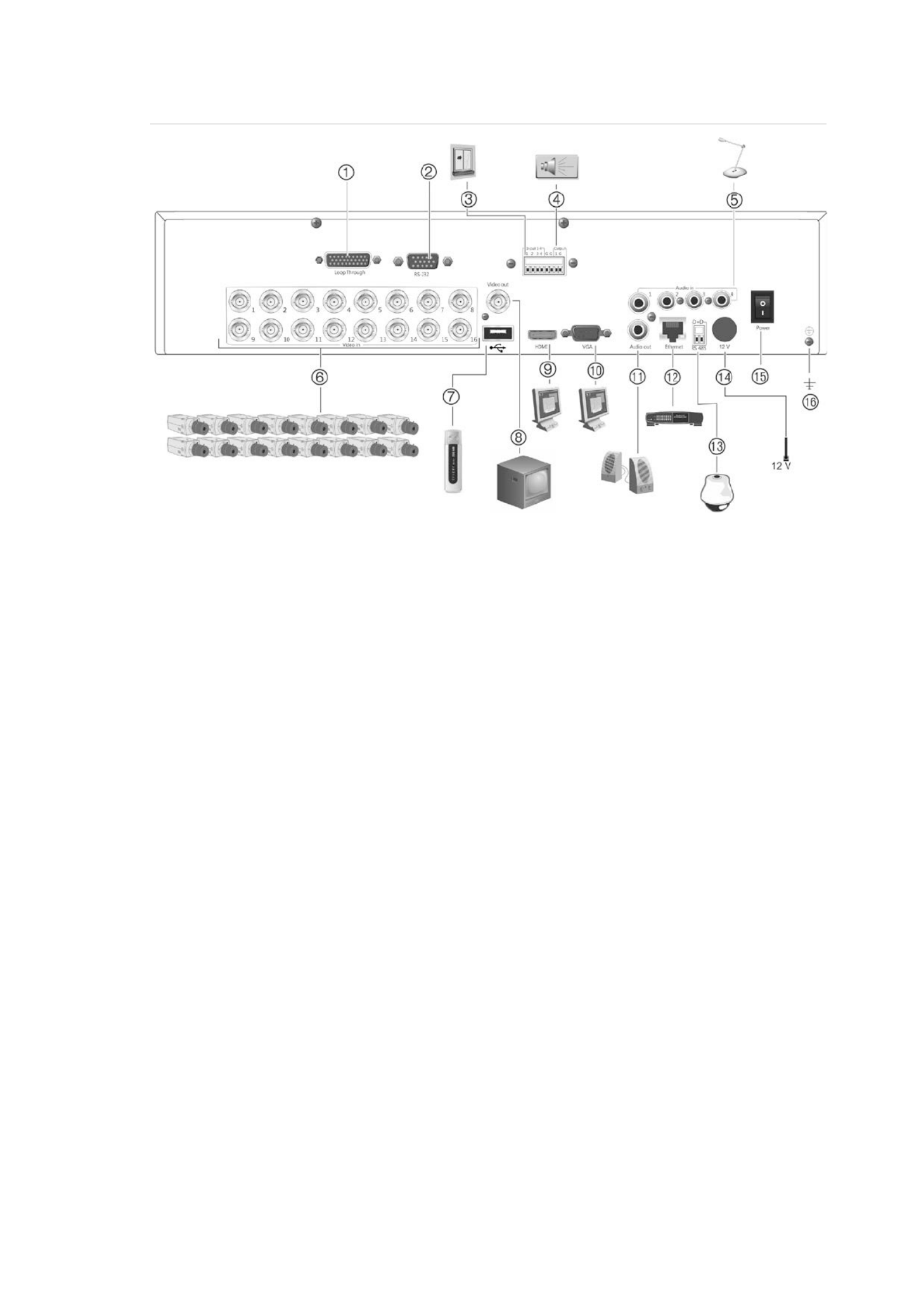
Figure : 1 TVR 11 back panel connections channel model shown) -(16
1. Loop through for up to 16 analog cameras
(depends on DVR model).
2. - Connect to a RS 232 device.
3. Connect up to four alarm input cables to
relay outputs.
4. . Connect one alarm relay output
5. Connect four audio inputs to RCA
connectors.
6. Connect up to 16 analog cameras to BNC
connectors (depends on model of DVR).
7. Connect to an optional USB device such as
a mouse, CD/DVD burner or HDD. The
DVR supports both a USB DVD and a USB
HD on the front and rear USB ports.
8. Connect one CCTV monitor (CVBS
connector).
9. Connect to a HDTV. The HDMI connection
supports both digital audio and video.
10 monitor.. Connect to a VGA
11. Connect to speakers for audio output.
12. Connect to a network.
13. Connect to a 485 device such as a RS- PTZ
camera or a keypad.
14 the . Connect to PSU (12 VDC).
15 (on/off). Power switch .
16. Connect to ground.
Monitor connections
Connect monitora to one of the DVR’s outputs (BNC/VGA/HDMI). The DVR
provides a 1 p CVBS signal. See -Vp Figure 1 above for connecting a monitor to a
DVR.
The DVR supports up to 1280 × 1024 / 60 Hz resolution in VGA. The monitor
resolution should be at least 800 × 600. Adjust your monitor accordingly to this
resolution.
1BChapter 2: Installation
6 TruVision DVR 11 User Manual
Audio inputs and output
The unit is equipped with audio inputs and four one audio output. Both the audio
output and the audio inputs are line-level.
Audio i
nput RCA jack, 315 mV, 40 hms. Unbalanced ko
Audio output
o RCA jack, 315mV, 600 hms. Unbalanced
Note: Line level audio requires amplification.-
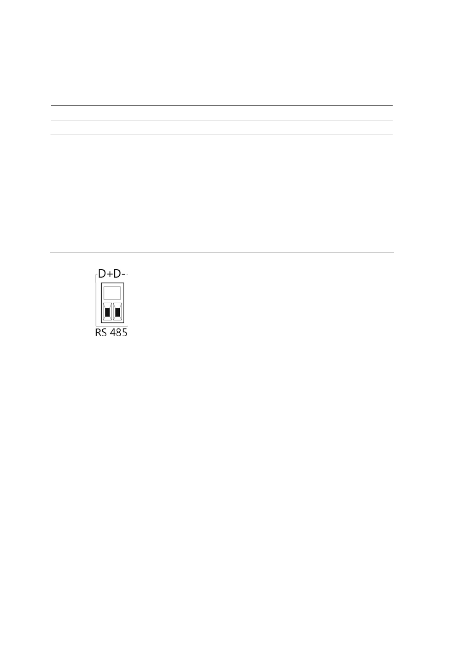
RS-485 port
There is one - RS 485 port on the back panel of the DVR to connect a PTZ dome
camera or keypad for the serial pin outs.. See Figure 3
Figure outs 2: RS- 485 pin
D+: Connect 485 Ato the RS- connection on the
dome camera or keypad.
D-: Connect 485 to the RS- B connection on the
dome camera or keypad.
RS- 232 port
Use the RS-232 port to connect CBR POS (point and ATM devices - -PB3 - -of sale)
to the DVR such as the UTC ProBridge accessory. “ -See Configuring the RS 232
port” on page 97 for more information.
PTZ dome camera set up
Use the USB mouse provided or the optional keypad for local telemetry control. If
using the over a network, use the web browser to control the PTZ domeDVR
cameras or TruVision Navigator.
See Appendix 123 B on page for the supported protocols, and Appendix F on
page 137 for the PTZ commands supported by each protocol.
Each PTZ camera must be set up individually. For information on configuring
PTZ dome camera settings, see Chapter 10 , “Controlling a PTZ camera” on page
71.
1BChapter 2: Installation
TruVision DVR 11 User Manual 7
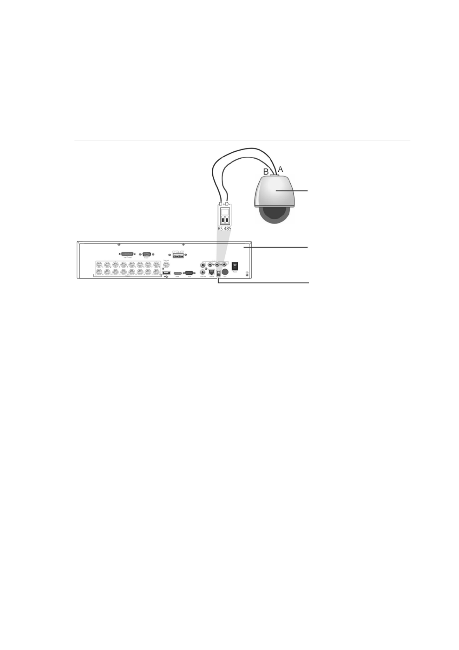
Connecting a PTZ dome camera
See below Figure 4 for how to connect a PTZ camera to the DVR. Any PTZ
dome camera can be controlled as the DVR is doing the PTZ protocol translation.
However, this setup provides only limited dome configuration (see Appendix B on
page 123 for the list of approved PTZ protocols).
Figure 3: Connecting a to the for control over the networkPTZ dome camera DVR
Dome camera
DVR back panel
RS- 485 port
Configuring the PTZ protocols for Interlogix cameras
Before the PTZ dome cameras are assembled in their housings, set their
protocol and address DIP switches for the DVR. See Table 3 on page 8 for
different Interlogix PTZ dome camera settings.
If you are using PTZ dome cameras from another company, please refer to their
configuration instructions.
1BChapter 2: Installation
8 TruVision DVR 11 User Manual
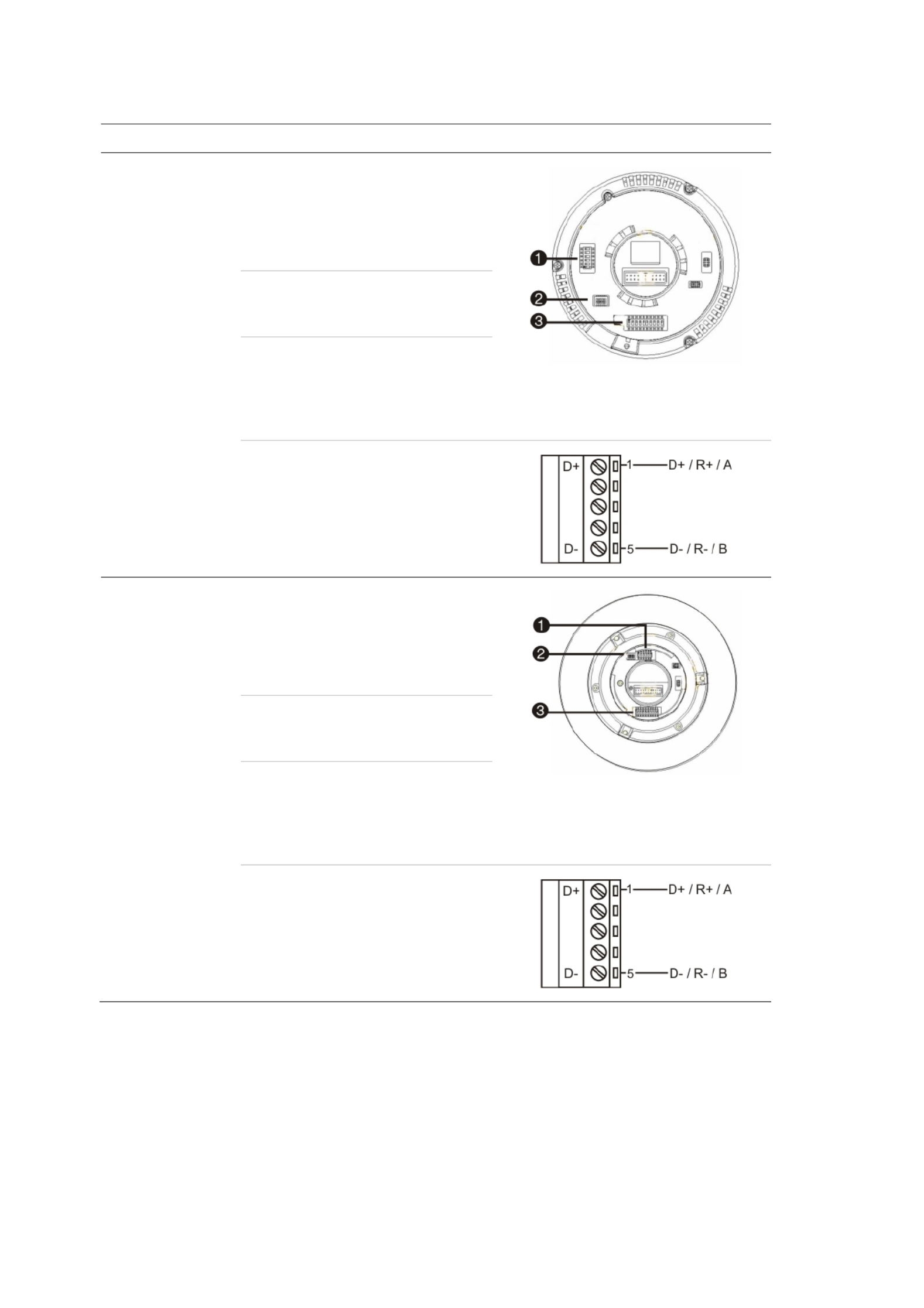
Table 2: PTZ protocols for Interlogix cameras
Camera
Switch setting
TruVision Mini PTZ
12X: Indoor Dome
Protocol DIP
switches:
• RS- 485 (on DVR): 000000
1. Protocol DIP switches
2. RS-485 communication DIP switches
3. Camera ID DIP switches
• RS-422 (on I/O
box):
100000
RS-485
communication DIP
switches:
110000
Camera ID DIP
switches:
Select the
camera ID
DIP switch
address as
required
RS- - 422/RS 485 data connector:
TruVision Mini PTZ
12X: Outdoor
Dome
Protocol DIP
switches:
• RS- 485 (on DVR): 000000
1. Protocol DIP switches
2. RS 485 communication DIP switches-
3. Camera ID DIP switches
• RS-422 (on I/O
box):
100000
RS-485
communication DIP
switches:
110000
Camera ID DIP
switches:
Select the
camera ID
DIP switch
address as
required.
RS- - 422/RS 485 data connector:

1BChapter 2: Installation
TruVision DVR 11 User Manual 9
Camera
Switch setting
TruVision Dome
16X PTZ
Protocol switches:
• RS- 485 (on DVR):
0111
1. Address switches; 2. Baud switches;
3. Protocol switches
• RS-422 (on I/O
box):
1111
Address switches: Select the
camera ID
DIP switch
address as
required.
Baud rate: 0000 =
9600 bps
0011 =
4800 bps
RS- - 422/RS 485 data connector:
CyberDome
Protocol switches: NA
Address switches: Select the
camera ID
DIP switch
address as
required.
RS- 485 data connector:

1BChapter 2: Installation
10 TruVision DVR 11 User Manual
Camera
Switch setting
UltraView PTZ
Protocol switches:
• RS-485 (on
D 0 VR): 1000
1. Protocol switches;
2. Address switches
• RS-422 (on I/O
box):
10000
Address switches: Select the
address
switch
address as
required.
RS- - 422/RS 485 data connector:
Legend
Protocol switches:
• RS- 485 on DVR):
1
• RS-422 (on I/O
box):
0
Address switches: Select the
camera ID
DIP switch
address as
required.
RS- - 422/RS 485 data connector:
1BChapter 2: Installation
TruVision DVR 11 User Manual 11
Connecting a KTD-405 keypad and dome
camera to the DVR
Use the input/output box that is supplied with the keypad to connect the KTD-405
keypad to the DVR. See Appendix D “ -KTD 405 keypad” on page 127 for more
information on wiring and using the KTD-405 keypad.
As the KTD-405 keypad uses full duplex data communication, you cannot
connect the both keypad and a dome camera directly to the DVR from the RS-
485 port as this could cause problems on the bus. If both devices are required, it
is recommended that you use the keypad’s RS-422 connection to connect the
dome camera and the keypad’s RS-485 connection to connect the DVR. See
Figure 5 as well as 4 Table and Table below. 5
Note: These connections only work with UTC PTZ protocols (see Appendix B on
page 123). If you are using another manufacturer’s PTZ protocol, it is not
possible to connect both keypad and dome camera to the a DVR.
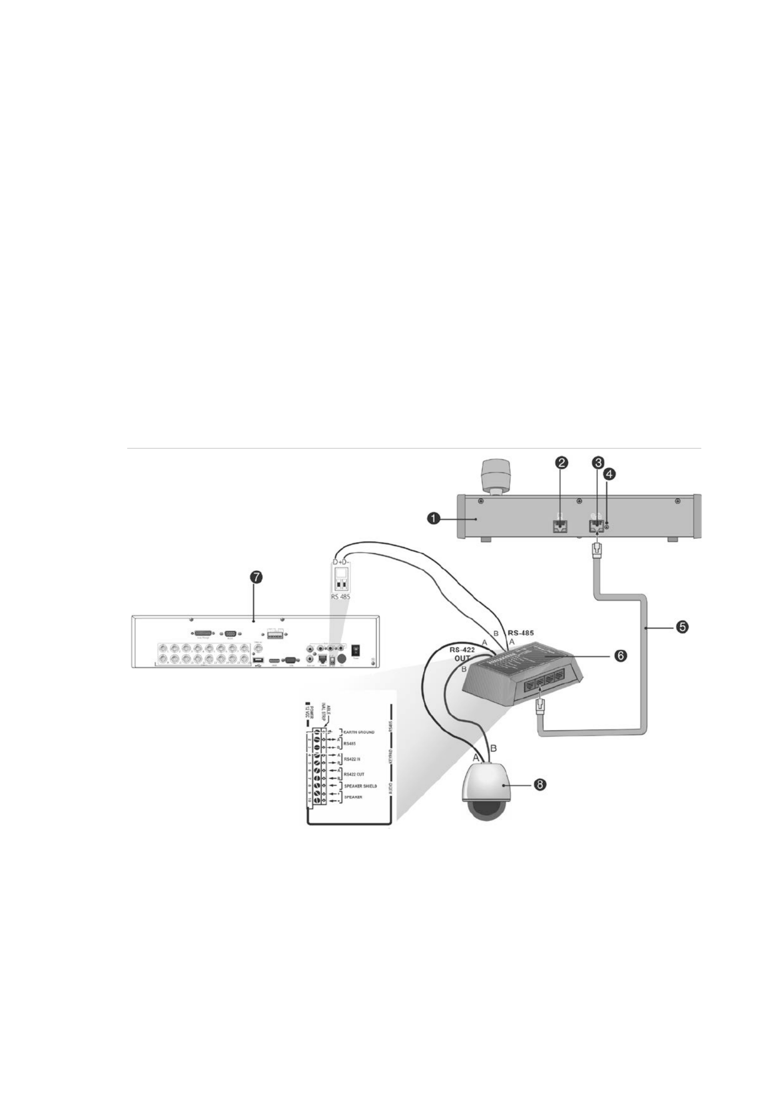
Figure 4: Connecting a PTZ dome camera and KTD- 405 keypad to the DVR
1. - KTD 405 keypad
2. - RS 232 programming port
3. - - RS 485 and RS 422 in/out
4. - RS 485 termination switch
5. RJ45 cable control (use the cable provided with
the equipment)
6. I/O box
7. DVR back panel
8. Dome camera

1BChapter 2: Installation
12 TruVision DVR 11 User Manual
Table 3: UTC PTZ protocol settings
Dome: RS
- -422 protocol TVR 11: Interlogix RS 485
See Table 5 below for the bus addresses to consider when connecting a both
keypad and dome camera to the DVR.
Table 4: Bus addresses
DVR bus address DVR video inputs PTZ address range
1 1- - 32 00 31
2 1- - 32 32 63
3 1- - 32 64 95
4 1- - 32 96 127
5 1- - 32 128 159
6 1- - 32 160 191
7 1- - 32 192 223
8 1- - 32 224 255
Brackets
The DVR is easily rack-mountable. It has a 1.5U chassis.
See belowFigure 6 .
Figure 5 -: Rack mount installation
To install the racks:
1. Attach the two small front-rack mount ears (A) to the DVR (supplied).
2. Attach the DVR to the front rails (screws not supplied). (B)

TruVision DVR 11 User Manual 13
Chapter 3
Getting started
Turning on and off the DVR
Before starting the power up process at least one monitor to the video , connect
out or the VGA interface. Otherwise, you will not be able to see the user interface
and operate the device. Also connect at least one camera.
The autoDVR -detects the video mode (PAL or NTSC) on startup.
It comes equipped with a universal power supply that will auto sense 110/240 - V,
60/50 Hz.
Note: It is recommended that an uninterruptible power supply (UPS) is used in
conjunction with the device.
To turn on the DVR:
Turn on the DVR using the power switch on the back panel. Once it is powered
up, the status LEDs on the front panel will light up. All connected cameras are
displayed on-screen. The DVR automatically begins recording.
To turn off the DVR:
1. In live view mode, right-click the mouse and click Menu. The main menu
window appears.
2. Select the Power Manager . icon
3. In the Shutdown popup menu, select to confirm Shutdown. Click Yes
shutdown.
To reboot the DVR:
1. In live view mode, right-click the mouse and click Menu. The main menu
window appears.
2. Select the Power Manager icon.
3. In the Shutdown popup menu, select to confirm shutdown.Reboot. Click Yes

2BChapter 3: Getting started
14 TruVision DVR 11 User Manual
Using the setup wizard
The has TVR 11 an express installation izard that lets you easily configure w
basic DVR settings when first used. It configures all cameras simultaneously.
The configuration can then be customized as required.
By default the setup wizard will start once the DVR has loaded. It will walk you
through some of the more important settings of your DVR.
Any changes you make to a setup configuration are saved when you exit page
the page and return to the main w izard page.
Note: If you want to set up the DVR with default settings only, click Next in each
screen until the end.
To quickly set up the DVR:
1. Connect all the devices required to the back panel of the DVR. See Figure 1
on page 5.
2. Turn on the unit using the power switch on the front panel. After the boot up
screen, the DVR displays video images on screen.
3. Select the preferred language for the system from the dropdown list and then
click . Next
4. Enable or disable the option to start the izard automatically when the DVR is w
turned on. Click Next.
5 . Administrator configuration:
Navigate to the Admin Password edit box and click the edit box with the
mouse, or press Enter on the front panel or remote control, to display the
virtual keyboard. Enter the default admin password, 1234.
Note: You must enter an admin password. To change the Admin password,
check New Admin password and enter the new password and confirm it.
Caution: It is strongly recommended that you change the password of the
administrator. Do not leave 1234 as the default password. Write it down in a
safe place so that you do not forget it.
If you should forget the password to your DVR, contact your supplier with the
serial number of your DVR to obtain a secure code to reset it.
Click Next.
6 : . Time and date configuration
Select the desired time zone, date format, system time, and system date.
Note: Daylight savings time (DST) cannot be configured from the Wizard. See
“Configuring time and date” on page 65 for more information on DST.

2BChapter 3: Getting started
TruVision DVR 11 User Manual 15
Note: The system time and date are visible on screen. However, they do not
appear in recordings.
Click Next to move to the next to return to the previous page, or Previous
page.
7. : Network configuration
Configure your network settings such as the NIC type, IP address, subnet
mask, and default gateway. Enter the preferred DNS server address as well
as the alternate one to use.
Click Next to move to the next to return to the previous page, or Previous
page.
8. HDD management:
Configure your HDD settings as required.
After configuring click your HDD settings, Initialize and Next to move to the
next page, or Previous to return to the previous page.
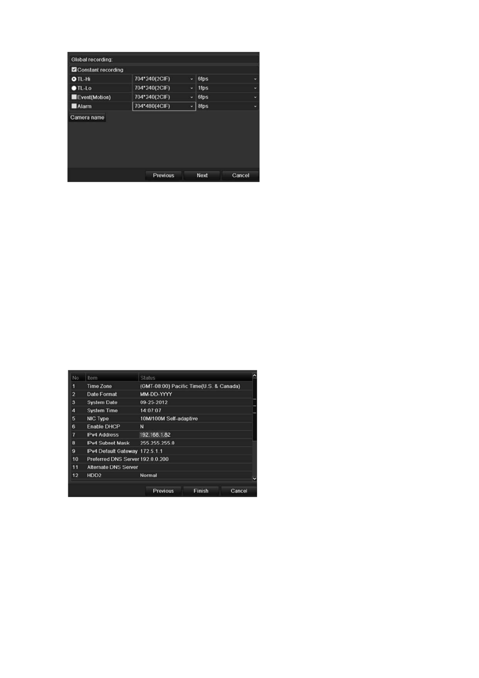
9. : Recording configuration
Configure your recording settings as required. The settings apply to all
cameras connected to the DVR.
2BChapter 3: Getting started
16 TruVision DVR 11 User Manual
Check the checkbox the Constant Recording for DVR to record continuously
all day. If left unchecked, the DVR will not record.
Check box elect check the TL-Hi and s its image resolution and frame rate.
Check the TL Lo- check box and select image resolution and frame rate.its
To record motion detection events, check Event (Motion) and select the
image resolution and frame rate.
To record alarm events, check Alarm and select the image resolution and
frame rate.
Under Camera name enter the camera name. A soft keyboard will appear to
enter the characters.
10. When all the required changes have been entered, a appearpage s showing
all the settings.
C lick Finish to exit the Wizard. The DVR is now ready to use.
For a description of the DVR main menu, see “Menu overview” on page 53.
: 3BChapter 4 Recording
TruVision DVR 11 User Manual 17
Chapter 4
Recording
This chapter provides instructions on how to define the recording settings of your
DVR. This chapter covers how you can configure your initial recording settings,
schedule recordings, and protect your recorded files.
Enter menu mode by pressing the Menu button on the front panel or use the
mouse menu to select Menu (see “Controlling live view” on page 58 for further
information). See Menu overview on page for a list of the menu icons. 53
Initializing the recording settings
Before you can set up your DVR to begin recording, you must first configure
general recording settings for the analog cameras.
Ensure that the HDD has been installed and initialized before configuring the
recording settings. See Chapter 7 “HDD management” on page 43 for more
information.
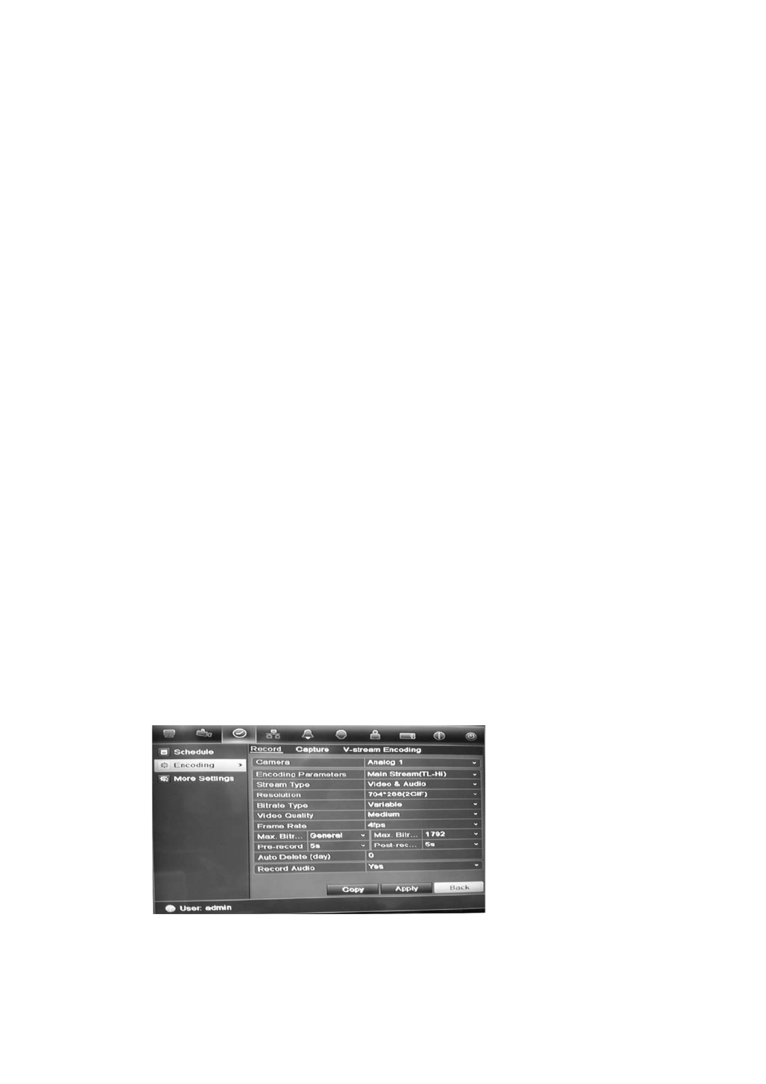
To configure recording settings:
1. In menu mode, click the Video Schedule icon in the menu toolbar.
2. Select Encoding > Record.
3. Select the camera you want to configure. Using the soft keyboard“ ” on page
54.

3BChapter 4: Recording
18 TruVision DVR 11 User Manual
4. Configure the following recording settings:
• Encoding parameters: Select one of the stream types: Main stream (TL-
Hi), Main stream (TL Lo), Main stream (Event), Main stream (Alarm), or -
Substream.
• Stream type: Select the type of stream to record, either video or video
and audio.
• Resolution: Select the resolution of the recording. Options include: 4CIF,
2CIF, CIF, and QCIF.
• Bit rate type: Select Constant or Variable.
• qVideo uality: Select the quality at which to record. If “Constant” was
selected as the bit rate type, this option is unavailable.
• rFrame ate: Select the recording frame rate. The options available
depend on the resolution selected. Real time (25 fps PAL/30 fps NTSC) is
only available when the selected resolution is CIF . and QCIF
• b r Max it ate mode: Select the general default or customized option.
• Max bit rate (kbps): If the customized maximum bit rate mode was
selected, enter the value here. It must be between 32 and 3172 kbps. It is
calculated from the frame rate and time required.
• -Pre record: This is the time the camera starts recording before the
scheduled time or event. Select the time in seconds to start pre record- ing
before the scheduled time or event.
The maximum pre-recording times available depend on the constant bit
rate. See Maximum pre recording times“ - ” on page 135 for more
information.
• -Post record: This is the time the camera continues to record after the
scheduled time or event. Select the time in seconds to stop post-recording
after the scheduled time or event.
• -Auto delete (day): Select the number of days after which recorded video
from the specified camera is permanently deleted from the HDD A “day” .
is defined as the 24 hour period from when the auto delete mode (ADM) -
was set.
The maximum number of days that can be set is 60. However, the actual
number of days permitted depends on the HDD capacity. the value is If set
to ‘0’ the option is disabled.,
• Record audio: Select Yes to record sound with the images.
5. Click Apply to save the settings.
6. If you want to save these parameters to another camera, click Copy and
select the camera in the pop up window that appears. Click and return to - OK
the main window.

: 3BChapter 4 Recording
TruVision DVR 11 User Manual 19
7. Click the Capture tab and configure the settings for captured video, such as
snapshots. Click to save the settingsApply .
8. Click Back to return to live view.
Defining a recording schedule
Defining a recording schedule lets you specify when the DVR records video and
under what circumstances. Each camera can be configured to have its own
recording schedule.
The schedules are visually presented on a map for easy reference. See Figure 7
below for an example.
Figure 6: Description of the schedule window
1. Camera. Select a camera.
2. Schedule time. Represents the 24-hour cycle during which a schedule is selected.
3. Schedule day. There are seven days to select: Sunday (Sun), Monday (Mon), Tuesday
(Tue), Wednesday (Wed), Thursday, (Thu), Friday (Fri), and Saturday (Sat).
4. Recording type. There are five recording types to select, which are color-coded:
( TL Time lapse Green squares): Record of a specific . Each day green square in the timeline
represents an hour in the 24 hour period- .
- a TL Hi (Dark green): High qu lity time lapse. Records high quality video.
- TL Lo (Bright green): Low quality time lapse. Records low quality video. This could be used,
for example, for night recordings when few events or alarms are expected. Saving the
video in low quality helps save resources on the HDD.
(Event Yellow): Record events, such as motion detection and POS/ATM text insertion.s only
s . Alarm (Red): Record only alarms
. None (Grey): No recording during this period
5 - . Timeline. There is a 24 hour time line for each day. Up to eight recording periods can be
scheduled during the 24 hour period.-

3BChapter 4: Recording
20 TruVision DVR 11 User Manual
Daily schedules
To set up a recording schedule:daily
1. Click the Video Schedule icon in the menu toolbar and select S . chedule
2. Select a camera.
3. Check the Enable Schedule box.
4. Click Edit. The following window is displayed:
5. Select the day of the week for which you want to set up the schedule.
You can define a different schedule for each day of the week.
6. Set the start and end time for recording.
Define a time period by entering a start (left column) and end (right column)
time. You can schedule up to eight time periods. Click All Day to record all
day.
Note: Time periods defined cannot overlap.
7. Select a recording type.
This setting instructs the DVR to begin recording when an alarm is triggered.
The recording type can be based on time and triggered by motion detection
and/or an alarm. If set to TimeLapse , the DVR records - -(TL Hi or TL Lo)
continuously.
8. Click Apply to save settings
9. Repeat steps 4 8 to for other days of the week copy the or to schedule
settings to another day.
To copy the current schedule settings to another day of the week, click Copy.
Select the number of the day of the week to which to copy the schedule. Click
OK to save changes and return to the Edit window.
10. Repeat steps 4 9 to for other cameras.
11. Click Apply to save the settings to return to the schedule and then OK
window.

: 3BChapter 4 Recording
TruVision DVR 11 User Manual 21
Holiday schedules
As well as being able to schedule when recordings occur during the week, you
can also schedule them for specific holidays in the year such as the first of
January, or the second Wednesday of every month, for example. You can
schedule up to 32 holiday periods.
A holiday period can be scheduled for a particular day or as a block of days.
To set up a holiday recording schedule:
1. Click the Display Mode Settings icon in the menu toolbar and select
Holidays.
2. Select a holiday period fro to modify the settings. The m the list and click Edit
Edit window appears.
3. Enter the name of the holiday period and click Enable.
4. Select whether the holiday period will be categorized by date, week or month ,
and then enter the start and end dates.
5. Click Apply to save the settings and then OK to return to the Edit window.
6. Repeat steps 2 5 to for other holiday periods.
7. Click Back to return to live view.
Motion detection schedules
You can set up both the schedule and areas sensitive to motion detection for
each camera individually or easily copy the settings of one camera to other
cameras.
For information on scheduling motion detections, see “Motion detection set up”
on page 26.
External alarm schedules
The DVR can be scheduled to record when an alarm is triggered by an external
alarm device such as a PIR detector or dry contacts. For information on

3BChapter 4: Recording
22 TruVision DVR 11 User Manual
scheduling external alarms, see “ or clearing Triggering alarm outputs manually”
on page 30.
Protecting recorded files
There are two methods to prevent recorded files from being inadvertently
overwritten or deleted off the HDD. We highly recommend that important
recorded events be protected from deletion. Recorded files can either be locked
or the HDD that the files reside on can be set to read only.
Locking and unlocking recorded files
Lock files to protect them against being overwritten or deleted.
To lock or unlock a recorded file:
1. v sIn live view enter the ideo earch window by pressing the Search button on
the front panel or remote control, and then enter Advanced Search.
— O — r
In live view right-click the mouse to display the pop-up menu and select
Advanced Search.
The Search window appears by default for the Normal tab .
2. Search for the desired recording by entering the search parameters, which
include the camera number, record type, file type, and start time and end
time.
3. Click Search.
A list of recordings, similar to the figure below, matching the search
parameters is displayed.

: 3BChapter 4 Recording
TruVision DVR 11 User Manual 23
4. Select the file you want to lock/unlock.
The Locked column indicates whether a file is locked or not.
5. Click to lock a file. Click again to unlock.
6. ick Cl Cancel to return to live view.
Setting the HDD to read only-
When you set an HDD to read-only, recorded video files cannot be written to the
HDD. If multiple HDDs are used, the DVR automatically records to the next HDD
not set to read- .only
To set a HDD to read-only:
1. Click the System Setting icon in the menu toolbar.
2. Click Hard Disk to set up the HDD parameters.
3. Select the HDD you want to set to read-only.
4. Check Read only.
5. Click Apply to save the settings. The HDD is now read-only.
Note: In order to enable recordings on that particular HDD again, you must
set the HDD status back to R/W (Read/ Write).
Capturing text insertions
T s -he DVR support Point of-Sale (POS) and ATM text insertion via the UTC
ProBridge accessory connected to the RS-232 port on the DVR.
The feature is currently only available via the browser (see “Capturing text
insertions” on page 118).


TruVision DVR 11 User Manual 25
Chapter 5
Alarm settings
This chapter describes setting up how the system will respond when an alarm is
triggered.
Enter menu mode by pressing the Menu button on the front panel or use the
mouse menu to select Menu (see “Controlling live view” on page 58 for further
information). See Menu overview on page for a list of the menu icons. 53
Description of alarm notification types
When setting up the rules for alarm detection, you can specify how you want the
DVR to notify you about an alarm. You can select more than one notification
type. Not all notifications types are available for all types of alarms.
The alarm notification types are:
• -Full screen monitoring: Triggers the camera image in alarm to appear as
full-screen view.
• Audible warning: Triggers an audible beep when a notification or alarm is
detected.
• Notify surveillance center: Sends a signal to TruVision Navigator or other
software applications when an alarm or notification is detected.
• Send email: Sends an email when an alarm or notification is detected. See
“Configuring email” on page 36 for information on how to configure the DVR
to send an email.
• oTrigger alarm utput: Triggers an alarm output when a notification is
detected for an external alarm. See “Setting up external alarms” on page 28
for information on configuring an alarm output.
Setting up motion detection
Motion detection is one of the most important features of a DVR. With it there is
no need to manually search through hours of video recordings to find an event.
4BChapter 5: Alarm settings
26 TruVision DVR 11 User Manual
The DVR can be set up to trigger an alarm if it detects motion and to record it.
You can then search these recorded motion activities for specific incidents. If
enabled, motion detection recording can help increase the number of days your
DVR can record.
You can mask out any areas of motion on an analog camera display that you do
not want to trigger a recording such as a flag on a pole or a moving tree.
Select the level of sensitivity to motion as well the target size so that only objects
that could be of interest can trigger a motion recording. For example, recording
is triggered by the movement of a person but not that of a cat.
You can set up both the schedule and areas sensitive to motion detection for
each camera individually or easily copy the settings of one camera to other
cameras.
Motion detection set up
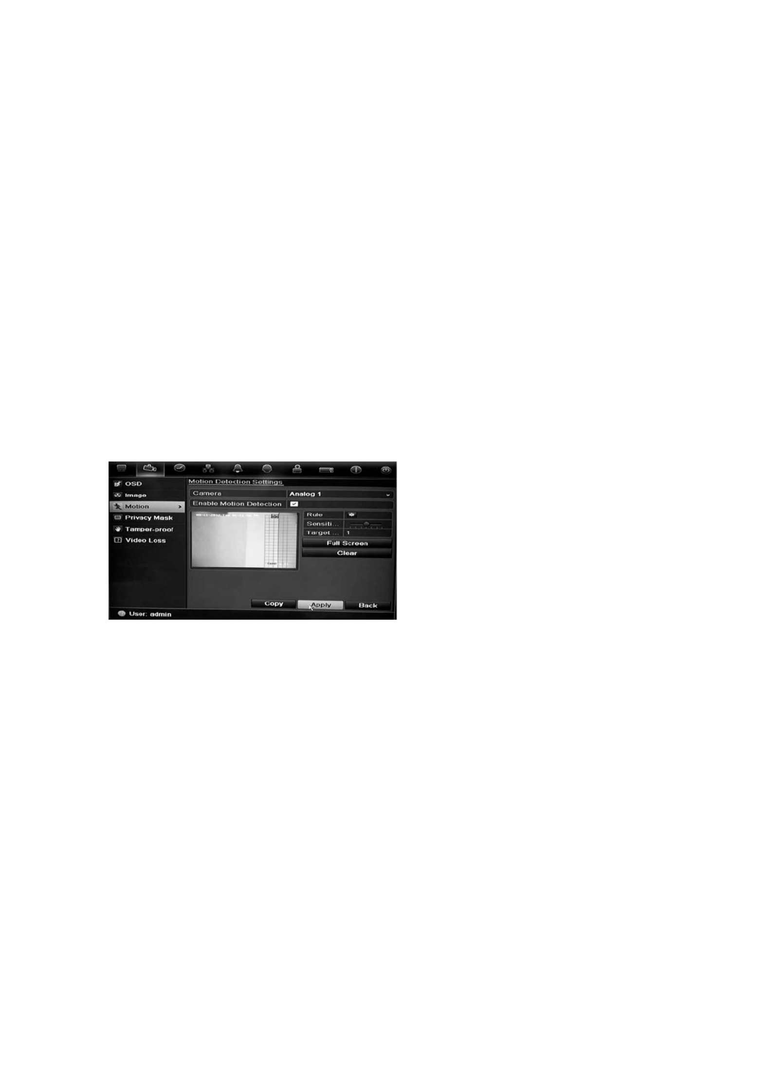
To set up motion detection:
1. Click the Camera Management icon in the menu toolbar and select . Motion
2. Select the analog camera to detect motion. Each camera must be set up
individually.
3. Check Enable Motion Detection.
4. Select the areas on-screen to be sensitive to motion.
Click and drag the mouse cursor across the window. The area selected
appears as a red grid. Areas covered by the red grid are sensitive to motion
detection.
Click Full screen to activate the whole screen or to clear the screen.Clear
5. Set the sensitivity level.
Drag the Sensitiv ty scroll bar to the desired sensitivity level. i The highest
value is on the right of the bar.
6. Specify the target size.
In the Target size option, specify how many grid squares must be activated
before motion is detected. Enter a value between 0 and 255 squares.
7. Select the cameras that will record the motion detected.

: 4BChapter 5 Alarm settings
TruVision DVR 11 User Manual 27
Click Rule. The Rule window appears. Click the tab and Trigger Channel
select the cameras that will record when a motion alarm is triggered. Click
Apply to save the settings.
8. Select the recording schedules for motion detection.
In the Rule window, click the Arming schedule tab and select the day of the
week and the time periods during the day when motion can be recorded. You
can schedule up to eight time periods in a day. Default is 24 hours.
Click Apply to save the settings. Click to copy the settings to other Copy
days of the week.
Note: Time periods defined cannot overlap.
9. Select the response method to motion detection.
In the Rule window, c tab to define the method by which you want lick the Rule
the DVR to notify you of the alarm to save settings. Click Apply .
10. Click OK rto eturn to the motion detection settings window.
11. Click Back to return to live view.
4BChapter 5: Alarm settings
28 TruVision DVR 11 User Manual
To trigger the front panel alarm LED:
1. Click the Display Settings icon in the menu toolbar and select
Monitor>More Settings.
2. Check both the Other Notification: Panel Alarm LED and Motion Alarm
boxes.
Setting up external alarms
The DVR can be configured to record when an alarm is triggered by an external
alarm device (for example, PIR detector, dry contacts…).
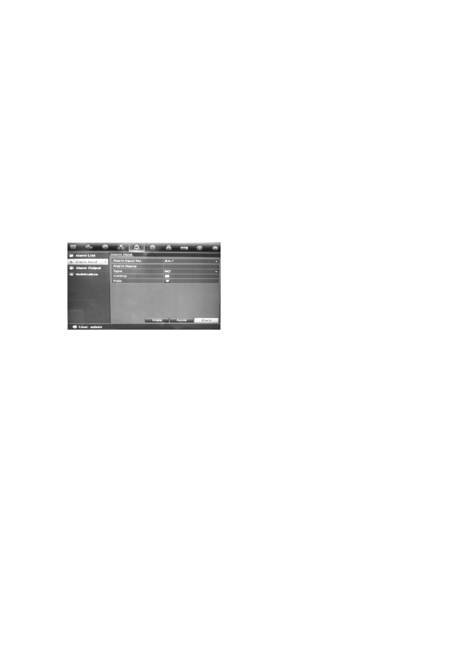
To set up external alarms:
1. Click the Alarm settings icon in the menu toolbar and select the Alarm Input
tab.
2. iSelect the alarm nput number of a camera and enter the name of the input, if
required.
3. Select the alarm input type, NO or NC.
4. Check the Setting box to enable the function and click et up the rules Rule to s
for the cameras to be triggered, their alarm schedules , method of alarm
notification and PTZ function.
5. Select the cameras to be triggered when an external alarm is detected.
In the Rule window, c and select the cameras to be lick Trigger channel
triggered for recording when an alarm analog cameras can is detected. Only
be selected. Click to save the settingsApply .
6. Select the recording schedules for the external alarm.
Click the Arming schedule tab and select the day of the week and the time
periods during the day when motion can be recorded. You can schedule up to
eight time periods in a day. Default is 24 hours.
Click Apply to save the settings. Click to copy the settings to other Copy
days of the week and holiday period.
Note: The time periods defined cannot overlap.
7. Select the response method to an external alarm.
: 4BChapter 5 Alarm settings
TruVision DVR 11 User Manual 29
Click the Rule tab to define the method by which you want the DVR to notify
you of the alarm ve settings. Click Apply to sa .
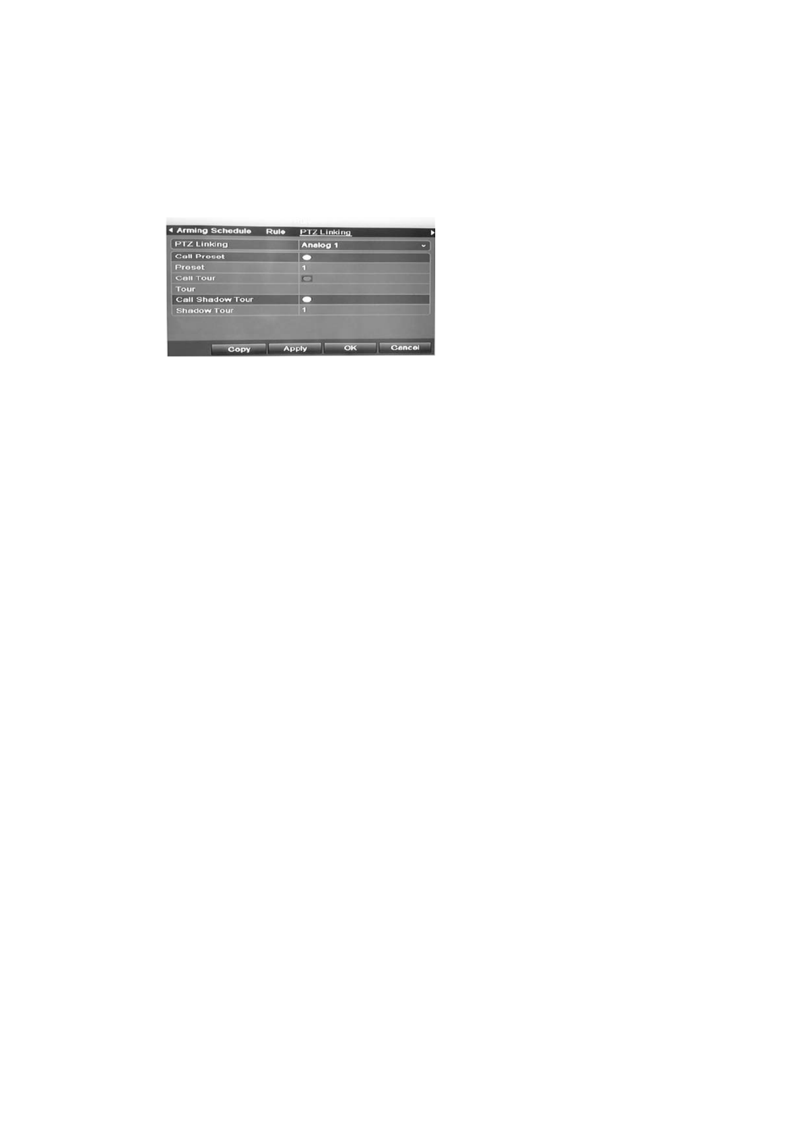
8. Select the PTZ camera function required in response to an external alarm.
Select the PTZ camera and the preset, preset tour or shadow tour that is
triggered when the alarm is detected.
Click Apply to save the settings. Click Copy to copy the settings to other
cameras, if required.
9. rClick OK to eturn to the alarm input window.
10. Click Back to return to live view.
To set up an alarm output:
1. Click the Alarm Settings icon in the menu toolbar and select Alarm Output.
2. Select the alarm output.
3. Select a timeout option.
The timeout setting lets you define how a signal remains active after the long
alarm has ended. If you select Manually Clear, the signal remains active until
it is manually acknowledged by pressing the alarm button on the front panel
or remote control (see “Triggering or clearing alarm outputs manually” on
page 30).
4. Select the recording schedules for the alarm output .
Click Rule and select the day of the week and the time periods during the day
when motion can be recorded. You can schedule up to eight time periods in a
day. Default is 24 hours.
Click Apply to save the settings. Click to copy the settings to other Copy
days of the week and holiday period.
Note: The time periods defined cannot overlap.
5 r. Click OK to eturn to the alarm output window.
6. Click Back to return to live view.

4BChapter 5: Alarm settings
30 TruVision DVR 11 User Manual
Triggering or clearing alarm outputs
manually
When an alarm is activated, the DVR can be set up so that the alarm must be
manually acknowledged in order to be silenced. Setting up external alarmsSee “ ”
on page 28 for information on setting up an alarm to be manually cleared.
All user levels (administrator, manager and operator) can manually acknowledge ,
an alarm.
To trigger alarm outputs manually: or clear
1. Click the Alarm settings icon in the menu toolbar and select . Alarm Output
2. Click the Manual Alarm tab.
3. Select the desired alarm output and click one of the following buttons:
• Trigger / Clear: Trigger an alarm output or stop an alarm output.
• Trigger All: Trigger all alarm outputs at once. This action could be done,
for example, when you need to test them.
• Clear All: Stop all alarm outputs at once.
4. Click Back to return to live view. The alarm is silenced.
- - Or
1. Press the Alarm button on the front panel or remote control. The alarm is
silenced.
Setting up system notifications
Setting up system notifications instructs the DVR to alert you when irregular
events occur and how to alert you to the event.
You can quickly check the system status by looking at the status LEDs on the
front panel. When there is an irregular event with the system, an icon appears on
screen to also alert you. See “Status information” on page 57 for further
information.
The types of system notifications include:
• HDD Full: All installed HDDs are full.
• HDD Error: Errors occurred while files were being written to the HDD, no
HDD installed or HDD had failed to initialize.
• Network Disconnected: Disconnected network cable.
• IP Conflicted: Conflict in IP address setting.
• Illegal Login: Wrong user ID or password used.
• Abnormal Video Signal: Unstable video signal or video loss detected.

: 4BChapter 5 Alarm settings
TruVision DVR 11 User Manual 31
• Input/output Video Standards Mismatch: I/O video standards do not
match.
• Abnormal Record: Recording failed due to encoder or hard disk problems.
See “Description of alarm notification types” on page 25 for information on the
different alarm notification types available.
To set up system notifications:
1. Click the Alarm settings icon in the menu toolbar and select . Notification
2. Select a notification type.
3. Check one or more response options: Audible warning, notify surveillance
center, send , trigger alarm output.email
4. Repeat steps 2 and 3 for other notification types.
5. Click Apply to save the settings.
Detecting video loss
Video may be lost if the video cable or camera develop a fault or are damaged.
You can set up DVR to detect video loss and trigger a the system notification.
To setup video loss detection:
1. Click the Camera management icon in the menu toolbar and select Video
Loss.
2. Select a camera to configure for video loss detection.
3. Check the Enable Video Loss Alarm box to enable the feature.
4. Click Rules next to the Video Loss Detection box to enter the Rules window.
5. Click the Rule tab and select how you want DVR to notify you of video the
loss (see page 25 for the list of options). Click Apply to save the settings and
then clock OK to return to the previous window.
6. Click the Arming Schedule e tab and s lect the schedule of when you want
video loss detection to be enabled. Schedule can be set for all week or any
day of the week with up to 8 time periods per day.
7. Click the Apply button to save settings.
8. Click Copy to copy these settings to other cameras.
9. Click Back to return to live view.

4BChapter 5: Alarm settings
32 TruVision DVR 11 User Manual
Detecting video tampering
You can setup the DVR to alert you when the camera view has changed such as
when someone has deliberately blocked the camera view by spraying paint on
the lens or by moving the camera. You can set it up so that a specific part of the
screen can detect a tamper and thereby trigger an action on the DVR.
Note: It is strongly recommended not to configure for video tampering when
using PTZ dome cameras.
To set up video tampering detection:
1. Click the Camera management icon in the menu toolbar and select Tamper-
Proof to display the tamper proof settings window.-
2. Select a camera to configure for video loss detection.
3. Check the Enable Tamper-proof box to enable the feature.
4. Define a tampering area.
The tamper detection area setup interface lets you define on screen an area
where you want camera tamper to be detected. Click and drag the mouse ing
across an area to mark that area for video tampering. You can only set one
tampering area with the full screen being the maximum area. Click Clear to
clear the window.
5. Select the tamper detection sensitivity level by clicking the sensitivity scroll
bar. Higher sensitivity is to the right of the bar.
6. Select the recording schedules for the tamper.
Click Rule and then select the Arming schedule tab to select the day of the
week and the time periods during the day when motion can be recorded. You
can schedule up to eight time periods . Default is 24 hours. in a day
Click Apply to save the settings. Click Copy to copy the settings to other
days of the week and holiday period.
Note: The time periods defined cannot overlap.
7. Select the response method to an external alarm.
Click Rule and then select the Rule tab to select the method by which you
want the DVR to notify you of the alarm to save settings and . Click Apply
then OK to return to the previous window.
8. Click Back to return to live view.

TruVision DVR 11 User Manual 33
Chapter 6
Network settings
You must configure your DVR’s network settings before using over the network.it
The DVR must have access to the internet when configuring the network
settings.
Note: As every network configuration may differ, please contact your Network
Administrator or ISP to see if your DVR requires specific IP addresses or port
numbers.
Configuring general network settings
To configure network settings:general
1. Click the Network settings icon in the menu toolbar to display its window.
2. Click General and enter the required settings:
Option Description
NIC type Network interface card (NIC) is a device used to connect the
DVR to a network. Select the NIC type used from the drop-
down
list.
Default value is 10/100M -self adaptive.

5BChapter 6: Network settings
34 TruVision DVR 11 User Manual
Option
Description
Enable DHCP
Check this box if you have a DHCP server running and want
your DVR to automatically obtain an IP address and other
network settings from that server.
Default value is Enable.
IPv4
address the Enter the IP address for . DVR
Default value is 192.168.1.82
IPv4 subnet mask
Enter the subnet mask for your network so the DVR will be
recognized within the network.
Default value is 255.255.255.0
IPv4 default gateway
Enter the IP address of your network gateway so the DVR will
be recognized within the
network. This is typically the IP address
of your router.
Default value is 192.168.1.1
IPv6 address 1
. Enter the IPv6 address for the DVR
Default value is fe80::240:3dff:fe7e:926f/64.
IPv6
address 2 address for Enter the IPv6 the . DVR
IPv6 default gateway
Enter the IPv6 address of your network gateway so the DVR will
be recognized within the
network. This is typically the IP address
of your router.
MAC address
Enter the MC address.
MTU (b
ytes) Enter a value between 500 and 9676. Default is 1500.
Preferred DNS server
Enter the preferred domain name server to use with the DVR.
Alternate DNS server
Enter the alternate domain name server to use with the DVR.
3. Click Apply to save the settings.
Configuring PPPoE
You can connect the DVR directly to a DSL modem. To do this, you need to
select the PPPoE option in the network settings. Contact your ISP to get the user
name and password.
To configure network settings:general
1. Click the Network settings icon in the menu toolbar to display its window.
2. Click PPPoE and check the enable PPPoE box.
3. Enter your user name and password and confirm the password.
4. Click Apply to save the settings.

: 5BChapter 6 Network settings
TruVision DVR 11 User Manual 35
Configuring DDNS
A static IP address never changes so you can enter it into the browser or CMS
and the DVR network connection will always work with it .
However, if you have a IP address for your dynamic public IP address, it will
change every time you connect to the network. Under such situations, you can
set up a dynamic domain name system (DDNS) that will link your public IP
address to a host name so that you can connect to the DVR with the host name.
There are two ways to set up a DDNS:
• DynDNS: Manually create your own host name. You will first need to create a
user account hosting web siteusing the , DynDDNS.org.
• ezDDNS: Activate the DDNS auto detection fu- nction to set up a dynamic IP
address. The server an available host name to your DVR. is set up to assign
Figure 7: ezDDNS setup window
NAT translates the ports on the server. Consequently there is no need to remember the ports
when connecting to the unit from the internet
Internal ports External ports These values can be modified . to
access several units over the internet
Note: This option is not shown when using the
browser.
Note: You cannot have two DVRs with the same host name.
To set up DDNS:
1. Click the Network settings icon in the menu toolbar.
2. Click DDNS to display its window.
3. Check the Enable DDNS box to enable this feature.
4. Select one of the DDNS types listed:
DynDNS: Select DynDNS and enter the server address for DynDNS
(members.dyndns.org). In the DVR domain name field, enter the domain
name obtained from the DynDNS web site. Then enter your user name and
password registered in the DynDNS network.
For example:

5BChapter 6: Network settings
36 TruVision DVR 11 User Manual
Server address: members.dyndns.org
Domain: mycompanydvr.dyndns.org
User name: myname
Password: mypassword
- - Or
ezDDNS: Select ezDDNS and enter your domain name. The server type entry
is prepopulated (www.tvr.ddns.net). If you will be connecting the unit via the
internet, check . Change the HTTP and server ports values, if required.NAT
The default values are 80 for the HTTP port and 8000 server port.
5. Click Apply to save the settings.
Configuring an NTP server
A Network Time Protocol (NTP) server can also be on your DVR to configured
keep the date and time current and accurate.
Note: If the device is connected to a public network, you should use a NTP
server that has a time synchronization function, such as the server at the
National Time Center (IP Address: 210.72.145.44) or europe.ntp.pool.org . If the
device is setup in a more customized network, NTP software can be used to
establish a NTP server used for time synchronization.
To set up an NTP server:
1. Click the Network settings icon in the menu toolbar.
2. Click NTP to display its window.
3. Check the NTP box to enable feature. It is enabled by default.
4. Enter the NTP settings:
• Interval: Time in minutes to synchronize with The value the NTP server.
can be between 1 and 10080 minutes. Default is 60 minutes.
• rNTP serve : IP address of the NTP server.
• NTP port: Port of the NTP server.
5. Click Apply to save the settings.
Configuring email
Your DVR can send notifications of alarms or notifications through the email
network.
Note: Ensure that the DNS address has been set up correctly beforehand.

: 5BChapter 6 Network settings
TruVision DVR 11 User Manual 37
To configure email settings:
1. Click the Network Settings icon in the menu toolbar.
2. eClick Email and nter the required settings.
Option Description
Enable server
authenticat oni
Check the box if your mail server requires authentication and
enter the login user name and password.
SMTP server Enter the SMTP server’s IP address.
SMTP port Enter the SMTP port. The default TCP/IP port for SMTP is 25.
Enable SSL Check the box to enable SSL if it is required by the SMTP server.
This feature is optional.
Sender email Enter the name of the sender of the .
Sender’s address the s Enter ender’s email address.
Select receivers Select an Up to three receivers can be selected. email recipient.
Receiver email Enter the name of the receiver of the .
Receiver’s address Enter the email address of the receiver.
Enable attached snapshot
Check the Attach JPEG File box if you want to send an email with
attached alarm images.
Interval Select an interval range in the Interval box.
The interval range represents the time range in between the alarm
images being sent. For example, if you set the interval range at
two seconds, the second alarm image will be sent two seconds
after the first alarm image
3. Click Test to the test email settings.
Note: We recommend that you test the email settings after entering values in
the email window.
4. Click Apply to save the settings.
Note: We recommend that you test the email settings after entering values in the
Email window.
Configuring SNMP
SNMP is a protocol for managing devices on networks. When you enable SNMP
in the menu, network management systems can retrieve DVR status information
from the DVR via SNMP.
When you set the trap address and trap port in the DVR menu to the network
management system’s IP address and port number and set, up the network
management system as trap receiver, trap notifications (such as startup) are sent
from the DVR to the network management system.
Before configuring this function, you must first install the SNMP software.

5BChapter 6: Network settings
38 TruVision DVR 11 User Manual
To configure SNMP protocol settings:
1. Click the Network settings icon in the menu toolbar.
2. eClick SNMP and nter the required settings.
3. Click Apply to save the settings.
Configuring a remote alarm host
If a remote alarm host set, the DVR sends a signal to the host when an alarm is
triggered. The remote alarm host must have the TruVision Navigator server
software installed.
To set up a remote alarm host:
1. Click the Network Settings icon in the menu toolbar.
2. . Click More Settings
3. Enter Alarm Host IP and Alarm Host Port.
Alarm host IP represents the IP of the remote PC where the Network Video
Surveillance software installed. The a h plarm ost ort value must be the same
as software’s alarm monitor port. Default port is 7200.
4. Click Apply to save the settings.
Configuring multicast
Setting up multicasting resolves limitation issues when streaming videos through
a network access device. A multicast address spans the Class-D IP range of
224.0.0.0 to 239.255.255.255. We recommend that the IP address range of
239.252.0.0 to 239.255.255.255 be used.
To set up multicasting:
1. Click Network Settings icon in the menu toolbar and then click More
Settings.
2. Enter a Multicast IP address.
Note: When adding a device to the Network Video Surveillance software, the
multicast address must be the same as the DVR’s multicast IP.
3. Click Apply to save the settings.

: 5BChapter 6 Network settings
TruVision DVR 11 User Manual 39
Configuring the server and HTTP p orts
You can change the server and HTTP ports from the default settings in the
Network Settings window. The default server port is 8000 while that of the default
HTTP port is 80.
Note: The s perver ort has a port range of 2000 65535 and is used for remote to
client software access. The HTTP port is used for remote internet browser
access.
To change the default ports:
1. Click the Network Settings icon in the menu toolbar and then click More
Settings.
2. Enter the new Com Port and HTTP Port values.
Configuring the RTSP service port
The RTSP (Real Time Streaming Protocol) is a network control protocol
designed for use in entertainment and communications systems to control
streaming media servers.
To configure RTSP service port:
1. Click the Network Settings icon in the menu toolbar and then click More
Settings.
2. Enter the RTSP port value. The default value 554 .
3. Click Apply to save the settings.
Checking network status
You can easily check network traffic in order to obtain information about the DVR
such as its linking status, MTU, sending/receiving rate, MAC address, and NIC
type.
You can also check the network connection status by testing its delay and packet
loss.
To check network traffic:
1. Click the System Settings icon in the menu toolbar and then click Net detect
to display the Traffic window. The information displayed is refreshed once a
second.

5BChapter 6: Network settings
40 TruVision DVR 11 User Manual
To check network delay and packet loss:
1. Click the System Settings icon in the menu toolbar and then click Net
detect.
2. Select the Network Detection Status tab.
3. Under the section “Network delay, Packet loss test”, enter the destination
address and click Test.
The test result appears in a pop up window.-
4. If you need to check the current network parameters, click the Network
button to get an overview.
The NIC type and Enable DHC options can be changed. P Click Apply to
save any changes made.
To check network statistics:
1. Click the System settings icon in the menu toolbar and then click Net
detect.
2. Select the Network Stat. tab.
3. The latest information is displayed on the bandwidth used by remote live and
playback as well by Net Receive Idle and Net Send Idle. Click Refresh to
update the information.

: 5BChapter 6 Network settings
TruVision DVR 11 User Manual 41
Exporting network packet data
When the DVR is connected to a network, you can export the captured data
packet to a, USB-flash drive, SATA/eSATA CD-RW and other local backup
devices.
To export network packet data:
1. Click the System Settings icon in the menu toolbar and then click Net
Detect.
2. Select the Network Detection tab.
3. Under the section “Network packet export”, click Refresh to get a list of the
local backup devices available. Select one from the list.
4. Click Export. Up to 1M of data can be exported at a time.

5BChapter 6: Network settings
42 TruVision DVR 11 User Manual

TruVision DVR 11 User Manual 43
Chapter 7
HDD management
Initializing HDDs
T -he in built HDD must be initialized before it can be used. You can also re-
initialize the HDD. However, all data on the HDD will be destroyed.
To initialize a HDD:
1. Click the System Settings icon in the menu toolbar and then click Hard Disk
to display its window.
2. Select the HDD to be initialized.
3. button Click the Initialize to begin initialization.
After the HDD has been initialized, the status of the HDD changes from
Abnormal to Normal.
Setting the HDD quota
You can allocate on a HDD the maximum permitted storage and snapshot picture
capacities from each camera.
1. Click the System Settings icon in the menu toolbar and then click Hard Disk.
2. Click the Storage mode tab.
3. Under the Mode option, select Quota.

6BChapter 7: HDD management
44 TruVision DVR 11 User Manual
4. Select a camera whose storage capacity you want to change and enter the
values in GB for maximum record capacity and maximum picture capacity.
The maximum storage capacity of the HDD is listed.
5. Click Apply tto save he settings.
6. If you want to copy these values to other cameras, click Copy and select the
cameras. Click . OK Click Apply to save the settings.
Setting the HDD property
You can change the behavior of your HDD by changing its property. It can be set
to read-only or read/write (R/W).
A HDD can be set to read only to avoid important recorded files from being -
overwritten when the HDD becomes full.
To change a HDD status property:
1. Click the System Settings icon in the menu toolbar and then click Hard Disk.
2. Click the HDD Information tab.
3. Select the HDD whose property you want to change.
4. Click the Edit icon . The Local HDD Settings window appears .
5. Click the desired HDD property for the selected HDD.
6. Click the group number for this HDD.
7. Click Apply to save and exit the window.
Note: Once set to read-only, the HDD cannot be used to save recorded files
until it is set back to read/write (R/W). If the HDD that is currently being
written to is set to read-only, the data is then recorded to the next HDD. If
there is only one HDD present, setting it to read-only means the DVR cannot
record.
Checking HDD status
You can check the status of any of the installed HDDs on the DVR at anytime.
To check the status of a HDD:
1. Click the System Settings icon in the menu toolbar and then click Hard Disk.
2. Note the status of the HDD listed under the Status column.s
If the status is listed as Normal or Sleeping, the HDD is in working order. If it
is listed as Abnormal and has already been initialized, the HDD needs to be
replaced. If the HDD is Uninitialized, you need to initialize it before it can be
used in the DVR. Refer to “Initializing HDDs” on page 43 for more information.
: 6BChapter 7 Operating instructions
TruVision DVR 11 User Manual 45
Note: This information is also available under System Settings > System
Information > HDD window.
Configuring HDD alarms
HDD alarms can be set to trigger when an HDD is uninitialized or in an abnormal
state.
To set HDD alarms:
1. Click the Alarm settings icon in the menu toolbar and select . Notification
2. Select the notification event to configure under Notification Type box.
3. Select HDD Full and check the desired notification method. See “Setting up
system notifications” on page 30 for more information.
Select HDD Error and check the desired notification method.
4. Click Apply to save the settings.
Checking the S.M.A.R.T. information
S.M.A.R.T -. (Self Monitoring, Analysis and Reporting Technology) reports on a
variety of hard drive attributes. It helps ensure that the HDD is functioning
properly at all times while protecting video stored on the hard drive.
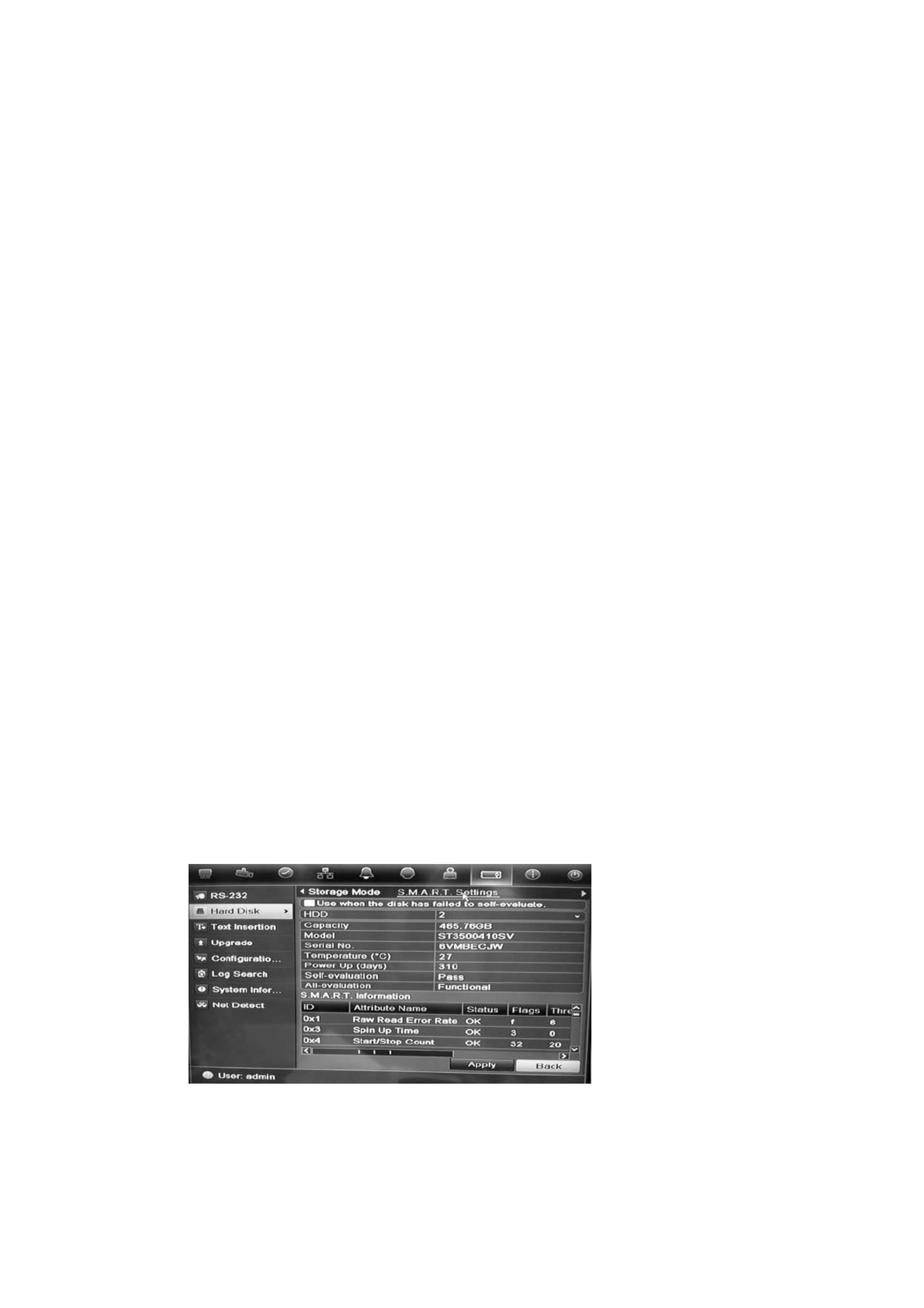
To view e S.M.A.R.T. th information of a HDD:
1. Click the System Settings icon in the menu toolbar and then click Hard Disk.
2. Select the S.M.A.R.T. tab to display its window.
3. Select the HDD whose data you want to see. A detail listing of S.M.A.R.T.
information is displayed.
4. If you want to continue to use a HDD when the S.M.A.R.T. test has failed,
check the box Use when the disk has failed to self-evaluate. Click Apply
to save the settings.

6BChapter 7: HDD management
46 TruVision DVR 11 User Manual

TruVision DVR 11 User Manual 47
Chapter 8
Operating instructions
Controlling the DVR
There are several ways to control the DVR:
• Front panel control
• Mouse control
• IR remote control
• -KTD 405 keypad control (see Appendix D “ -KTD 405 keypad” on page 127)
• Web browser control
You can use your preferred control method for any procedure, but in most cases
we describe procedures using mouse terminology. Optional control methods are
given only when they differ substantially from mouse control methods.
Using the front panel
The function buttons on the front panel control can be used to operate many, but
not all, of the main functions of the DVR. The LED indicators light up to alert you
of various conditions. The functions available can be limited by setting
passwords. See Figure 9 on page 48 for more information.

7BChapter 8 Operating instructions:
48 TruVision DVR 11 User Manual
Figure 8: TVR 11 front panel ch model shown) -(16
The controls on the front panel include:
Item
Name Description
1
. USB port The DVR supports both a USB DVD and a USB HD on the
front and rear USB ports.
2
. c. CD/DVD burner Insert CD or DVD dis
The CD/DVD burner is not present on all TVR 11 models.
Not all menus are available on models without a burner.
3
. Eject button Ejects CD/DVD disc. This is only present on models with a
CD/DVD burner.
4
. Archive button Press once to enter quick archive mode. Press twice to
start archiving.
5
. Display and Seq
buttons
Live view mode: Press Display to toggle through the
various views single and multiviews . Press Seq
to start/stop
sequencing in live view mode.
Menu mode: Press Enter to select a menu window and
then Seq
to toggle through the tabs along the top of a menu
window.
6
. Channel buttons Switch between different cameras in live view, PTZ control
or playback modes.
7
. Live, Menu and Search
buttons
Live: Switch to live view mode.
Menu: . Enter/exit the main menu
Search: E nter the advanced search menu.
8
. Status LEDs HDD: Green indicates the DVR is working correctly. Red
indicates a fault.
Network: Green indicates the network is working correctly.
Red indicates a fault or no network connection.
Internal: Green indicates the Watchdog is working
correctly. Red indicates that the Watchdog is reporting a
fault.
Alarm: Green indicates indicates no external alarm. Red
an
external alarm status or motion.
9
. Alarm button Use to manually acknowledge an alarm.

: 7BChapter 8 Operating instructions
TruVision DVR 11 User Manual 49
Item
Name Description
10
. Enter and arrows
button
Use to select options in a menu and to control playback.
Press for Enter.
Live view mode: Press Enter to enter/exit PTZ mode.
Press the arrow buttons to scroll between the left/right
cameras.
Menu mode: To enter the menu toolbar, keep pressing the
left arrow button until the first menu icon is selected. Then
press the left/right arrow buttons to select a menu icon.
To select a menu option in the submenu panel or setup
menu, press the arrow buttons left/right and up/down to
position cursor in the menu window. Press for Enter. See
Figure 12 on page 53.
Playback mode: Press the left/right arrow buttons to slow
down or speed up playback. Press the up/down arrow
buttons to jump forwards or backwards by 30 seconds.
Press Enter to stop/start playback.
PTZ mode: Press the arrow buttons to control the
movement of the PTZ dome camera.
11
. IR receiver Receiver for IR remote.
12
. Playback buttons : Press to jump back to the oldest available video and
start the playback.
: Press to pause playback.
-: Press to start all day playback of the currently
selected camera. If you are in multiview format, only the
camera shown in the top left corner of- the multiview is
played back.
Using the mouse
The USB mouse provided with the DVR can be used to operate all the functions
of the DVR, unlike the front panel which has limited functionality. The USB
mouse lets you navigate and make changes to settings in the user interface.
Connect the mouse to the DVR by plugging the mouse USB connector into the
USB port on the back panel or the front panel. The mouse is immediately
operational and the pointer should appear.
Note: Use a USB 2.0 or higher mouse.
Move the pointer to a command, option, or button on a window. Click the left
mouse button to enter or confirm a selection.
You can purchase a spare mouse by ordering part number TVR- -MOUSE 1
TruVision™ DVR Model 11/40/41/60 Mouse.
See Table 6 on page 50 for a description of the mouse buttons.

7BChapter 8 Operating instructions:
50 TruVision DVR 11 User Manual
Table 5 : Mouse buttons
Item
Description
Left button
- Single Click Live view: Select a camera to display the quick
access toolbar (see “Accessing frequently used
commands” on page 61).
Menu: Select a component of a menu, such as a
button or an input field. This is similar to pressing the
Enter button on the remote/front panel controls.
Double- Click Live view: Switch between single screen and multi-
screen mode in live/ playback mode.
Click and Drag : Drag channel/time bar. Live view
PTZ control: Adjust pan, tilt and zoom.
Tamperproof, privacy mask and motion ing
detection functions: Select the target area.
Digital zoom- in: Drag and select target area.
Right button
- : Single Click Live view Display menu.
Menu: Exit the current menu and return to higher
level.
Scroll
- wheel Scroll Up Live view: Return to the previous window.
Menu: Move the selection to the previous item.
Scroll Down Live view: Move to the next window.
Menu: Move the selection to the next item.
Using the IR remote control
The DVR is supplied with an infra red (IR) remote control unit. Like the mouse, it
can be used to operate all of the main functions of the unit.
The IR remote control can be programmed with a unique device ID address so
that the controller will only be able to communicate with DVRs with that address.
No programming is necessary if using a single DVR.
The device ID address only applies when using a remote control and not when
using a keypad.
You can purchase a remote control by ordering part number TVR- -REMOTE 1
TruVision™ DVR Model 11/40/41/60 IR Remote Control.

: 7BChapter 8 Operating instructions
TruVision DVR 11 User Manual 51
Figure 9: IR remote control
Item
Description
1
. Alarm
Acknowledge an alarm.
2
. Device
Enable/disable the IR remote control to control the
DVR.
3
. Numeric buttons
Select a camera, and enter a number in a menu option.
4
. Display
Switch
. between the different multiview formats
5
. B Mon A and Mon
Switch
between monitors A and B.
6
. Live
Return to
live view mode.
7
. Menu
Activate the main menu.
8
. Seq
Start /stop
sequencing.
9
. , , ,
In Menu mode: Use left or right arrow buttons to select and up or down
arrow buttons to edit entry.
In PTZ mode: Use to control PTZ.
In Playback mode: Use to control playback speed.
10
. OK
Confirm selection.
11
. - Zoom + and
Use to control zoom of camera lens.
12
. Preset
Enter preprogrammed three
- digit code to call up a preset.
13
. Tour
Enter preprogrammed three
- digit code to call up shadow tour.

7BChapter 8 Operating instructions:
52 TruVision DVR 11 User Manual
Item
Description
14
. - Focus + and
Use to control focus of camera lens.
15
. Playback control
Use to control playback (Rewind, Pause, Play, and Fast Forward).
16
. Search
Open the Search menu.
17
. Replay
Replay the selected file from the beginning.
18
. Eject
Eject the CD or DVD disk.
1
9. Archive
Press once to enter quick archive mode. Press twice to start archiving.
Aim the remote control at the IR receiver located at the front of the unit to test
operation.
To connect the remote control to the DVR:
1. Press the Menu button on the front panel or right the mouse and select - click
the Menu button. The main menu window appears.
2. . Click Display Mode Settings > Monitor
3. Check the device address value. The default value is 255. This device
address is valid for all IR controls.
Note: The DVR will respond to any remote control that has an address
between 1 and 255.
4. On the remote control press the Device button.
5. Enter the device address value. It must be the same as that on the DVR.
6. Press the OK button on the remote control.
To place batteries into the IR remote control:
1. Remove the battery cover.
2. Insert the batteries. Make sure that the positive (+) and negative (−) poles are
correctly placed.
3. Replace the battery cover.
Troubleshooting the remote control:
If the IR remote control is not functioning properly, perform the following tests:
• Check the battery polarity.
• Check the remaining charge in the batteries.
• Check that the IR remote control sensor is not masked.
If the problem still exists, please contact your administrator.

: 7BChapter 8 Operating instructions
TruVision DVR 11 User Manual 53
Menu overview
The DVR has an icon driven menu structure that allows you to configure the-
unit’s parameters. Each command icon displays a that lets you edit a window
group of settings. Most menus are available only to system administrators.
The window is divided into three sections. The currently selected command icon
and submenu item are highlighted in green. See Figure 12 below .
You must be in live view mode to access the main menu.
Figure 10: structureM enu
1. Menu toolbar: Setup options available for the selected menu function. Move the mouse over
a 7 command icon and click to select it. See Table below for a description of the icons.
2. Submenu panel: Submenus for the selected menu function are displayed. Click an item to
select it.
3. Setup menu: All the details for the selected sub are displayed. Click a field to make menu
changes.
Note: See for the description on how to access the menu Figure 9 on page 48
options using the front panel.
Table menu 6: Description of the toolbar icons
I con Name Description
Display
mode settings Configures display settings including dwell time, schedule,
language and display formats. See “Configuring live view”
on page and “Holiday schedules63 ” on page 21.
Camera
management Configures camera settings including motion detection,
video image adjustments, camera title, and copy settings to
other cameras. See Camera settings on page 97“ ” “.
Video schedule
Configures recording settings including recording
schedules, record quality, auto delete mode, and recording
mode. See Chapter Recording 4 “ ” on page 17.
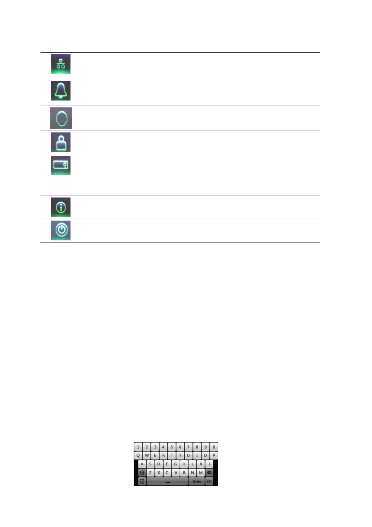
7BChapter 8: Operating instructions
54 TruVision DVR 11 User Manual
I con Name Description
Network
settings Configures standard network settings including IP address,
email notifications, DDNS setup, and advanced network
settings. Chapter See 6 “Network settings on page ” 33.
Alarm settings
Configures alarm settings including alarm input, relay
output, video loss, remote alert, pre- , alarm and post-alarm
seconds. See Chapter 25 5 “Alarm settings” on page .
PTZ
“settings Configures PTZ settings. See Chapter 10 Controlling a
PTZ camera” on page 71.
User
management Configures users, passwords, and access privileges. See
Chapter 15 “ ” . User management on page 107
System settings
Configures system settings including system date and time,
audio output, device name, RS 485 settings, RS- -232
settings, firmware upgrade, hard drive settings, boot log,
and shutdown. HDD management See Chapter 7 “
” on page
43 and Chapter 13 management 97 “DVR ” on page .
Help
information Provides reference information to the various toolbars,
menus, and keys within the interface.
Pow
e , r manager Provides access to logout, reboot and shutdown options.
See 13“Turning on and off the DVR on page” .
To access the main menu:
1. In live view press the Menu button on the remote control or front panel.
- - Or
R - , ight click the mouse and select Menu from the pop-up menu.
The main menu window appears. The Display window appears by default.
2. Click the required menu icon to display its submenu options. Modify the
configuration parameters as required.
3. Click Apply to save the settings.
4. Click Back to return to live view.
Using the soft keyboard
A keyboard will appear on screen when you need to enter characters in a -
window option. Click a key to input that character.
Figure 11: The soft keyboard

: 7BChapter 8 Operating instructions
TruVision DVR 11 User Manual 55
Description of the keys in the virtual keyboard:
Switch to lowercase/uppercase
Space
Exit the soft keyboard
Alphanumeric characters
Backspace
Symbols
Confirm selection
Exiting the main menu
Press the Menu button on the front panel to exit the current menu window and
return to live view, or click Back in a main menu.

7BChapter 8 Operating instructions:
56 TruVision DVR 11 User Manual

TruVision DVR 11 User Manual 57
Chapter 9
Live view
Description of live view
Live view mode is the normal operating mode of the unit where you watch live
images from the cameras. The automatically enters into live view modeDVR
once powered up. On the viewer you can see whether a recording is in progress
and, if set up to do so, the current date and time, as well as the camera name.
S tatus information
Information on the system and status is displayed camera as icons on the main
and auxiliary monitors. The camera status icons are shown for each camera.
Each icon represents information on a specific item. These icons include:
Table screen 7 -: Description of the on status icons
Icon
Description
Indicates a sensor alarm.
Indicates recording (such as manual recording, motion detection or alarm-
triggered recording).
Indicates a event.motion detection
Indicates a video loss event.
Indicates alarm and system notifications. Clicking the icon opens a window that
lists the alarms and notifications.
The DVR can display more than one icon at the same time. See “General
settings” on page 66 to display or hide these icons.
The system status is displayed on the front panel by the status LEDs.
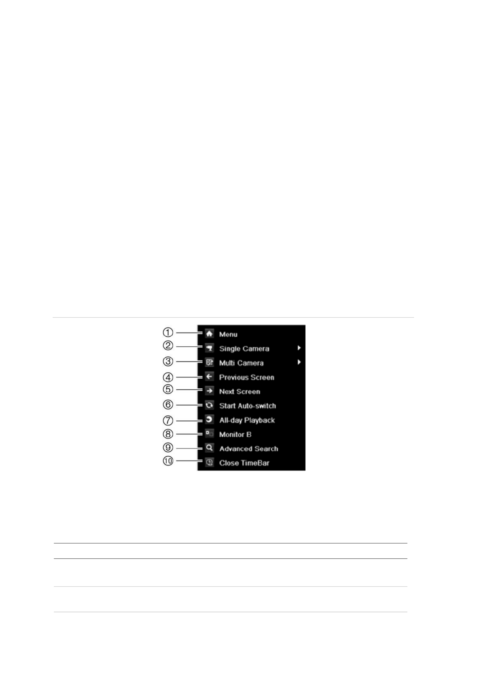
8BChapter 9: Live view
58 TruVision DVR 11 User Manual
Video output
The DVR automatically checks the monitor outputs used. If more than one
monitor is connected, it then defines which monitor is the main one and which is
the event one The event monitor is used to display. detected events such as
motion. On ly one monitor can be controlled at a time.
If a HDMI monitor is used, it will be the main output. If HDMI and VGA monitors
are both connected to the DVR, both will be main monitors; they will both show
the same view. However, you will not be able to control each individually.
See “ ” on page for more information on setting up the Controlling live view 58
monitors.
Controlling live view
Many features of live can be quickly accessed by placing the cursor on a view
live image and clicking the right-button of the mouse. The mouse menu appears
(see 14 belowFigure ).
Figure 12: ouse itorThe m menu for the main mon
The list of commands available depends on which monitor is active main or ;
auxiliary (monitor B). See Table 9 below. The default settings of these
commands are provided in Appendix G “, Default menu settings” on page 137.
Table ouse menu 8 M: for monitor A (main monitor)
Item
Name Description
1.
M enu Enter the Main menu.
This option is not available from monitor B.
2.
- Single camera Switch to a full screen view for the selected camera from
the dropdown list.
3.
Multi camera Switch between the different multiview options from the
dropdown list.

: 8BChapter 9 Live view
TruVision DVR 11 User Manual 59
Item
Name Description
4.
Previous screen Displays the previous camera.
5.
Next screen Displays the next camera.
6.
- Start auto switch Turn on sequence mode. The window automatically
sequences between cameras on page 60. See “Multiview” .
Go to Display Mode Settings Menu > > Layout Dwell>
Time
t . o set up
7.
- All day playback Playback the recorded video of the selected day from the
selected camera . The current day is selected by default.
See 82 for“ -All day playback” on page more information.
8.
( ). Monitor B Switch between monitors A (main) and B event
9.
“Advanced search Enter the advanced video search menu. See Searching
recorded video” on page more information.83 for
10.
. Close time bar Open/close the time bar
Table ouse menu 9 M: for monitor B (event monitor)
Item
Name Description
1
. -Single camera Switch to a full screen view for the selected camera from
the dropdown list.
2
. Multi camera Switch between the different multiview options from the
dropdown list.
3
. Previous screen Displays the previous camera.
4
. Next screen Displays the next camera.
5
. - All day playback Playback the recorded video of the selected day from the
selected camera. The current day is selected by default.
See “ on page more information.All-day playback” 82 for
6
. A . Monitor Switch between monitors A (main) and B (event)
Single and multiview display formats
The DVR has single- view display format as well as four multiview formats.
Single view display format
Press the numeric button on the front panel to switch to the corresponding
camera display. For example, press button to view camera 10.10
Right-click the mouse and select Single Camera from the menu. Select the
camera required . from the list

8BChapter 9: Live view
60 TruVision DVR 11 User Manual
M ultiview display format
A video tile is any cell in a multiview display. A camera can only be shown image
in one video tile at a time. The number of multiview display formats available
depends on the DVR model. See belowFigure 15 .
To change the multiview display that appears by default, go to the Display menu.
See “Changing the camera sequence for more information” on page 64 .
Figure 13: TVR 11 multiview display formats
4- channel DVR:
8/16-channel DVR:
To select a multiview display format:
1. Press the Display button on the front panel to cycle through different display
formats.
You can also right-click the mouse and select Multi Camera from the menu.
Select the desired multiview display layout.
Sequencing cameras
The sequencing feature allows a camera to be displayed briefly on screen,
before advancing to the next camera in the sequence list. Sequencing can only
be done in mode. single-view display
The default sequence displays each camera in numerical order. However, each
camera on the main and auxiliary monitors can have a pre programmed dwell -
time and sequence order. See “Changing the camera sequence” on page 64 for
more information.
Note: Dwell time must not be set to zero for sequencing to function.

: 8BChapter 9 Live view
TruVision DVR 11 User Manual 61
Sequencing live view mode : using the front panel
1. Select the camera where you want to start sequencing.
2. Press the Seq button on the front panel to start sequencing .
3. Press the Seq button again to stop the sequencing.
Sequencing live view mode using the mouse:
1. Select the camera where you want to start sequencing.
2. -Right click the mouse and select Start auto-switch to start the sequencing.
3. -Right click the mouse and select Stop auto-switch to stop the sequencing.
Accessing frequently used commands
The quick access toolbar in live view lets you quickly access regularly used
commands. Position the cursor over a video image and left- click the mouse. The
toolbar appears (see Figure 16 61 on page ).
Figure 14: toolbarQuick access
Table 10 : Description of the quick access toolbar icons
Icon Description
Freeze: Freeze the live image of the selected camera. Although the image
pauses, time and date information does not. The system clock continues to run.
Instant playback: Playback the recorded video from the last five minutes. If no
recording is found, then there was no recording made in the last five minutes.
Click the icon and select the desired camera. Click OK.
See “Instant play ” on page for more information.back 81
Audio: Enable/Disable audio output. The audio option must already have been
setup in the Display menu.
Quick snapshot: Capture a snapshot of a video image. The image is saved
on
the unit. See “Slideshow of snapshots” on page for more information.86
PTZ control: Enter PTZ control mode.
See “ Configuring PTZ settings” on page 71 for more information.
Digital zoom: Enter digital zoom. on page See “Digital zoom” 62 for further
information.

8BChapter 9: Live view
62 TruVision DVR 11 User Manual
Icon Description
Image settings: Enter the image settings menu to modify the image lighting
levels. There are two options:
Preset Mode: eThese are preconfigured image lighting levels. S lect one of the
four options depending on current lighting conditions:
- Standard: Use in standard lighting situations.
- Indoor: Use indoors.
- Dim Light: Use when the light level is low.
- Outdoor: Use when outdoors. The contrast and satur ation values are
high.
Customize: Modify brightness, contrast, saturation and hue values., Click
Restore to restore image settings to previous values.
Click Restore to restore image settings to previous values.
These settings can also be modified from the Camera>Image menu (see page
“ . Adjusting video image settings on page ” 105
Close toolbar: Close the shortcut toolbar.
Digital zoom
You can easily zoom in or out of a camera image in live view mode and playback
using the digital zoom command. The zoom command magnifies the camera
image four times. See Figure 17 below .
Figure 15: Digital zoom window
To quickly zoom in/out on a camera image:
1. Select the camera you wish to use.
2. -Left click the mouse and select the digital- zoom icon. The digital view window
appears.

: 8BChapter 9 Live view
TruVision DVR 11 User Manual 63
3. -Left click the mouse and drag the red square to the area of interest, or press
the arrow button on the front panel to position the red square. The selected
area is magnified.
4. To exit digital zoom, - right click the mouse.
Configuring live view
The setup of live can be view modified from the main menu to suit different
needs, such as the different monitors, multiview layout, and dwell time options.
You can also enable audio output.
In the Layout menu use the Video output interface, Live view mode, Dwell time,
and Enable audio output settings to configure the main monitor. Use Event
output and Full screen monitoring dwell time settings to configure the event
monitor.
Figure 16: Layout window (G eneral tab)
Table 11 : Description of the layout window
Submenu name
Description
Video output interface
/ Select which monitor will be the main monitor: HDMI VGA, or main
CVBS.
Default is HDMI/VGA, if connected.
Live view
. mode Select which multiview layout will be default in live view mode The
factory default format multiview displays all channels (3x3 layout for
the 4 and 4x4 layout for the 8/16-channel TVR 11 -channel 11TVR ).
D
well time Set the length of time for which a camera image is displayed on the
selected monitor before moving to the next camera during
sequencing. Default is off . (“No switch”)

: 8BChapter 9 Live view
TruVision DVR 11 User Manual 65
To set the camera sequencing:
1. Click the Display Mode Settings icon in the menu toolbar.
2. > . Select Layout View
3 . From Video Out Iput nterface, select the desired monitor from the drop -down
list.
4. From the multiview layout selection bar, select the des layout.ired multiview
5. Select the video tile of the camera whose order you want to change. The
selected tile is highlighted green.
6. In the selected tile, select the new camera sequence order by scroll ing the
through the list of available camera numbers.
Note: “X” means that the camera is not displayed.
7. Click Apply to save the settings.
8. Click Back to return to live view.
Configuring time and date
You can set up the date and time that will appear on screen as well as on time -
stamped recordings. The start and end time of daylight savings time (DST) in the
year can also be set. DST is deactivated by defaul for the t. See Figure 20 below
Time settings screen.
Figure 18: Time and date settings window
Produkt Specifikationer
| Mærke: | Interlogix |
| Kategori: | Overvågningskamera |
| Model: | TruVision TVR-1108 |
Har du brug for hjælp?
Hvis du har brug for hjælp til Interlogix TruVision TVR-1108 stil et spørgsmål nedenfor, og andre brugere vil svare dig
Overvågningskamera Interlogix Manualer

23 September 2024
13 September 2024
8 September 2024
1 September 2024
12 August 2024
9 August 2024
8 August 2024
8 August 2024
7 August 2024
6 August 2024
Overvågningskamera Manualer
- Overvågningskamera Bosch
- Overvågningskamera Denver
- Overvågningskamera Sony
- Overvågningskamera Canon
- Overvågningskamera Netis
- Overvågningskamera Samsung
- Overvågningskamera Panasonic
- Overvågningskamera Extech
- Overvågningskamera Moog
- Overvågningskamera TP-Link
- Overvågningskamera Philips
- Overvågningskamera Vitek
- Overvågningskamera Gigaset
- Overvågningskamera Pioneer
- Overvågningskamera Mitsubishi
- Overvågningskamera Braun
- Overvågningskamera Logitech
- Overvågningskamera Emos
- Overvågningskamera Google
- Overvågningskamera Technaxx
- Overvågningskamera HP
- Overvågningskamera Waeco
- Overvågningskamera Garmin
- Overvågningskamera Sanyo
- Overvågningskamera Grundig
- Overvågningskamera D-Link
- Overvågningskamera Arlo
- Overvågningskamera Motorola
- Overvågningskamera Asus
- Overvågningskamera Toshiba
- Overvågningskamera Pyle
- Overvågningskamera Kodak
- Overvågningskamera Furrion
- Overvågningskamera InFocus
- Overvågningskamera Nedis
- Overvågningskamera Friedland
- Overvågningskamera Abus
- Overvågningskamera Planet
- Overvågningskamera Adj
- Overvågningskamera Hama
- Overvågningskamera Creative
- Overvågningskamera Thomson
- Overvågningskamera Belkin
- Overvågningskamera Edimax
- Overvågningskamera Burg Wächter
- Overvågningskamera Clas Ohlson
- Overvågningskamera DataVideo
- Overvågningskamera Strong
- Overvågningskamera TRENDnet
- Overvågningskamera Smartwares
- Overvågningskamera Trevi
- Overvågningskamera Trust
- Overvågningskamera Laserliner
- Overvågningskamera Blaupunkt
- Overvågningskamera JVC
- Overvågningskamera Honeywell
- Overvågningskamera Uniden
- Overvågningskamera Buffalo
- Overvågningskamera Linksys
- Overvågningskamera Megasat
- Overvågningskamera Cisco
- Overvågningskamera EZVIZ
- Overvågningskamera König
- Overvågningskamera Elro
- Overvågningskamera Gembird
- Overvågningskamera Powerfix
- Overvågningskamera Alpine
- Overvågningskamera Netgear
- Overvågningskamera Maginon
- Overvågningskamera Yale
- Overvågningskamera Withings
- Overvågningskamera Nest
- Overvågningskamera Kerbl
- Overvågningskamera Vtech
- Overvågningskamera Exibel
- Overvågningskamera Genie
- Overvågningskamera Vaddio
- Overvågningskamera Bresser
- Overvågningskamera Western Digital
- Overvågningskamera Anker
- Overvågningskamera Digitus
- Overvågningskamera Zebra
- Overvågningskamera Jensen
- Overvågningskamera Alecto
- Overvågningskamera Flamingo
- Overvågningskamera Rollei
- Overvågningskamera Olympia
- Overvågningskamera Xiaomi
- Overvågningskamera Niceboy
- Overvågningskamera Aiptek
- Overvågningskamera Schneider
- Overvågningskamera B/R/K
- Overvågningskamera Marmitek
- Overvågningskamera Tesla
- Overvågningskamera Imou
- Overvågningskamera Ricoh
- Overvågningskamera Nexxt
- Overvågningskamera Aida
- Overvågningskamera APC
- Overvågningskamera Foscam
- Overvågningskamera Lorex
- Overvågningskamera Ikan
- Overvågningskamera Velleman
- Overvågningskamera LevelOne
- Overvågningskamera Marshall
- Overvågningskamera FLIR
- Overvågningskamera Perel
- Overvågningskamera Swann
- Overvågningskamera Vivotek
- Overvågningskamera Joblotron
- Overvågningskamera JUNG
- Overvågningskamera ORNO
- Overvågningskamera Binatone
- Overvågningskamera ZyXEL
- Overvågningskamera Fortinet
- Overvågningskamera Netatmo
- Overvågningskamera Tenda
- Overvågningskamera Eufy
- Overvågningskamera Ring
- Overvågningskamera M-e
- Overvågningskamera Overmax
- Overvågningskamera Somfy
- Overvågningskamera Y-cam
- Overvågningskamera Hikvision
- Overvågningskamera Monacor
- Overvågningskamera ION
- Overvågningskamera Raymarine
- Overvågningskamera Ubiquiti Networks
- Overvågningskamera AVerMedia
- Overvågningskamera EnGenius
- Overvågningskamera Reolink
- Overvågningskamera Grandstream
- Overvågningskamera Trebs
- Overvågningskamera EVE
- Overvågningskamera Renkforce
- Overvågningskamera Marshall Electronics
- Overvågningskamera Manhattan
- Overvågningskamera SPC
- Overvågningskamera Caliber
- Overvågningskamera Pentatech
- Overvågningskamera Switel
- Overvågningskamera AVtech
- Overvågningskamera LogiLink
- Overvågningskamera Orion
- Overvågningskamera Eminent
- Overvågningskamera Kramer
- Overvågningskamera QSC
- Overvågningskamera Hanwha
- Overvågningskamera Brilliant
- Overvågningskamera Lanberg
- Overvågningskamera Hive
- Overvågningskamera Siedle
- Overvågningskamera BirdDog
- Overvågningskamera Evolveo
- Overvågningskamera Genius
- Overvågningskamera KJB Security Products
- Overvågningskamera Valueline
- Overvågningskamera Provision-ISR
- Overvågningskamera Quantum
- Overvågningskamera Axis
- Overvågningskamera ACTi
- Overvågningskamera CRUX
- Overvågningskamera Avanti
- Overvågningskamera Vimar
- Overvågningskamera Aluratek
- Overvågningskamera Dahua Technology
- Overvågningskamera Chacon
- Overvågningskamera SereneLife
- Overvågningskamera ZKTeco
- Overvågningskamera AG Neovo
- Overvågningskamera Stabo
- Overvågningskamera EtiamPro
- Overvågningskamera First Alert
- Overvågningskamera Speco Technologies
- Overvågningskamera Boss
- Overvågningskamera Broan
- Overvågningskamera Conceptronic
- Overvågningskamera Avidsen
- Overvågningskamera Crestron
- Overvågningskamera Lindy
- Overvågningskamera Kogan
- Overvågningskamera AVMATRIX
- Overvågningskamera Delta Dore
- Overvågningskamera Promise Technology
- Overvågningskamera Sitecom
- Overvågningskamera DiO
- Overvågningskamera Minox
- Overvågningskamera Intellinet
- Overvågningskamera V-TAC
- Overvågningskamera Qian
- Overvågningskamera August
- Overvågningskamera IDIS
- Overvågningskamera Geovision
- Overvågningskamera Schwaiger
- Overvågningskamera Steren
- Overvågningskamera Elmo
- Overvågningskamera AViPAS
- Overvågningskamera UniView
- Overvågningskamera Equip
- Overvågningskamera Alfatron
- Overvågningskamera REVO
- Overvågningskamera Aqara
- Overvågningskamera Ernitec
- Overvågningskamera Setti+
- Overvågningskamera BZBGear
- Overvågningskamera PTZ Optics
- Overvågningskamera AVer
- Overvågningskamera Ferguson
- Overvågningskamera Moxa
- Overvågningskamera Inovonics
- Overvågningskamera Bea-fon
- Overvågningskamera Profile
- Overvågningskamera WyreStorm
- Overvågningskamera Allnet
- Overvågningskamera Aldi
- Overvågningskamera Airlive
- Overvågningskamera Aritech
- Overvågningskamera ACME
- Overvågningskamera KlikaanKlikuit
- Overvågningskamera Marquant
- Overvågningskamera Ednet
- Overvågningskamera Lumens
- Overvågningskamera Hombli
- Overvågningskamera Naxa
- Overvågningskamera Miniland
- Overvågningskamera Xavax
- Overvågningskamera Gira
- Overvågningskamera DSC
- Overvågningskamera Boyo
- Overvågningskamera Iget
- Overvågningskamera EverFocus
- Overvågningskamera Adesso
- Overvågningskamera Satel
- Overvågningskamera Notifier
- Overvågningskamera Monoprice
- Overvågningskamera Beafon
- Overvågningskamera Chuango
- Overvågningskamera MicroView
- Overvågningskamera ETiger
- Overvågningskamera Videcon
- Overvågningskamera INSTAR
- Overvågningskamera Advantech
- Overvågningskamera Digital Watchdog
- Overvågningskamera Moen
- Overvågningskamera Ganz
- Overvågningskamera MEE Audio
- Overvågningskamera Mobotix
- Overvågningskamera Kwikset
- Overvågningskamera Ikegami
- Overvågningskamera Leviton
- Overvågningskamera Pelco
- Overvågningskamera Approx
- Overvågningskamera ClearOne
- Overvågningskamera Ebode
- Overvågningskamera Oplink
- Overvågningskamera Dorr
- Overvågningskamera Sonic Alert
- Overvågningskamera Linear PRO Access
- Overvågningskamera Summer Infant
- Overvågningskamera SMC
- Overvågningskamera Topica
- Overvågningskamera Iiquu
- Overvågningskamera Verint
- Overvågningskamera Brinno
- Overvågningskamera Rostra
- Overvågningskamera Caddx
- Overvågningskamera Spyclops
- Overvågningskamera EKO
- Overvågningskamera Kguard
- Overvågningskamera Woonveilig
- Overvågningskamera Accsoon
- Overvågningskamera Mobi
- Overvågningskamera Surveon
- Overvågningskamera Hollyland
- Overvågningskamera Epcom
- Overvågningskamera Indexa
- Overvågningskamera Lutec
- Overvågningskamera Whistler
- Overvågningskamera ClearView
- Overvågningskamera VideoComm
- Overvågningskamera IMILAB
- Overvågningskamera 3xLOGIC
- Overvågningskamera Inkovideo
- Overvågningskamera Weldex
- Overvågningskamera SecurityMan
- Overvågningskamera Mach Power
- Overvågningskamera Canyon
- Overvågningskamera CNB Technology
- Overvågningskamera Tapo
- Overvågningskamera Aigis
- Overvågningskamera Exacq
- Overvågningskamera Brickcom
- Overvågningskamera Laxihub
- Overvågningskamera Securetech
- Overvågningskamera EFB Elektronik
- Overvågningskamera NetMedia
- Overvågningskamera Videotec
- Overvågningskamera Illustra
- Overvågningskamera Atlona
- Overvågningskamera Nivian
- Overvågningskamera Arenti
- Overvågningskamera E-bench
- Overvågningskamera Blow
- Overvågningskamera Syscom
- Overvågningskamera Tecno
- Overvågningskamera Night Owl
- Overvågningskamera Guardzilla
- Overvågningskamera Astak
- Overvågningskamera Blink
- Overvågningskamera Milestone Systems
- Overvågningskamera Zavio
- Overvågningskamera Campark
- Overvågningskamera IPX
- Overvågningskamera Dedicated Micros
- Overvågningskamera Hamlet
- Overvågningskamera Annke
- Overvågningskamera Qoltec
- Overvågningskamera Digimerge
- Overvågningskamera Feelworld
- Overvågningskamera Wisenet
- Overvågningskamera Infortrend
- Overvågningskamera Epiphan
- Overvågningskamera HiLook
- Overvågningskamera Compro
- Overvågningskamera Vimtag
- Overvågningskamera Sonoff
- Overvågningskamera Gewiss
- Overvågningskamera Alula
- Overvågningskamera Insteon
- Overvågningskamera Costar
- Overvågningskamera ALC
- Overvågningskamera Security Labs
- Overvågningskamera Comtrend
- Overvågningskamera Seneca
- Overvågningskamera Avigilon
- Overvågningskamera American Dynamics
- Overvågningskamera Vosker
- Overvågningskamera Sentry360
- Overvågningskamera Owltron
- Overvågningskamera Petcube
- Overvågningskamera Enabot
- Overvågningskamera Luis Energy
- Overvågningskamera Sir Gawain
- Overvågningskamera VisorTech
- Overvågningskamera Atlantis Land
- Overvågningskamera B & S Technology
- Overvågningskamera I3International
- Overvågningskamera Ecobee
- Overvågningskamera Turing
- Overvågningskamera Wasserstein
- Overvågningskamera Qolsys
- Overvågningskamera Control4
- Overvågningskamera Milesight
- Overvågningskamera GVI Security
- Overvågningskamera Conbrov
- Overvågningskamera HuddleCamHD
- Overvågningskamera Defender
- Overvågningskamera IOIO
- Overvågningskamera BIRDFY
- Overvågningskamera I-PRO
- Overvågningskamera DVDO
- Overvågningskamera TCP
- Overvågningskamera Bolin Technology
- Overvågningskamera Nextech
- Overvågningskamera Tuya
- Overvågningskamera Bolide
- Overvågningskamera Telycam
- Overvågningskamera Arecont Vision
- Overvågningskamera Schlage
Nyeste Overvågningskamera Manualer
7 April 2025
7 April 2025
6 April 2025
29 Marts 2025
28 Marts 2025
20 Marts 2025
20 Marts 2025
20 Marts 2025
13 Marts 2025
8 Marts 2025