Lifetime 60042 Manual
Læs nedenfor 📖 manual på dansk for Lifetime 60042 (96 sider) i kategorien Haveskur. Denne guide var nyttig for 15 personer og blev bedømt med 4.5 stjerner i gennemsnit af 2 brugere
Side 1/96

Scan the code, or visit go.lifetime.com/60042playlist
OR WATCH THE HOW-TO ON YOUTUBE
3D ANIMATION
OF THE FULL ASSEMBLY
WATCH
SCAN THE
CODE
OR SEARCH
1200510
YouTube® and the YouTube logo are trademarks of Google, LLC.
Icon Legend...............................4
Warnings & Notices.....................5
Platform Construction.................6
Truss Assembly.........................11
Gable Assembly........................15
Door Assembly..........................18
Floor Assembly.........................29
Wall Assembly...........................33
Window Installation...................42
Door & Gable Installation...........45
Parts Identifi er..........................47
Roof Assembly..........................55
Door Alignment........................72
Shed Anchoring........................75
Latch Installation......................78
Shelf Installation......................87
Cleaning & Care........................91
Registration...........................92
Warranty..............................93
TOOLS REQUIRED TABLE OF CONTENTS
7/16" (11 mm)
3/8" (10 mm)
5/16" (8 mm) Wood Drill Bit
5/16" (8 mm) Masonry Drill Bit
BEFORE ASSEMBLY:
• Assemble on a level surface
• At least 3 adults recommended for setup
Pour le français, voir la page 2. Para el español, ver la página 3.
ASSEMBLY INSTRUCTIONS
7'x7' (2.13 x 2.13 m)
OUTDOOR STORAGE SHED
MODEL 60042
CONTACT LIFETIME® CUSTOMER SERVICE:
Call: 1-800-225-3865
7:00 am–5:00 pm (Monday–Friday) MST
and 9:00 am–1:00 pm Saturday MST
Live Chat: www.lifetime.com/customerservice
(click on “LIVE CHAT” tab)
QUESTIONS?
MODEL# AND PRODUCT ID (both are needed when contacting us)
Model Number: 60042
Product ID:
For Customer Service in mainland Europe:
E-mail: cs@lifetimeproducts.eu

2
Scanner le code, ou visiter go.lifetime.com/60042playlist
OU REGARDER LA VIDÉO SUR YOUTUBE
ANIMATION 3D
DE L'ASSEMBLAGE COMPLET
REGARDER
SCANNER LE
CODE OU CHERCHER
1200510
YouTube® et le logotype YouTube sont des marques déposées de Google, LLC.
Légende des icônes.....................4
Avertissements et avis.................5
Assemblage de la plate-forme......6
Assemblage des fermes.............11
Assemblage des pignons............15
Assemblage des portes..............18
Assemblage du plancher...........29
Assemblage des murs...............33
Installation des carreaux............42
Installation des portes..............45
Identifi cateur de pièces.............47
Assemblage du toit...................55
Alignement des portes...............72
L’ancrage de l’abri.....................75
Installation du loquet.................78
Installation du rayonnage...........87
Nettoyage et entretien...............91
Enregistrement........................92
Garantie..............................94
OUTILS REQUIS SOMMAIRE
AVANT L’ASSEMBLAGE :
• Assembler sur une surface de niveau
• Nous recommendons, au moins, 3 adultes pour l’assemblage
For English, see page 1. Para el español, ver la página 3.
INSTRUCTIONS D’ASSEMBLAGE
ABRI EXTÉRIEUR DE
2,13m x 2,13m
MODÈLE n° 60042
7/16 po (11 mm)
3/8 po (10 mm)
Foret à boit de 8 mm
Foret à maçonnerie de 8 mm
CONTACTER AUX SERVICES À LA CLIENTÈLE LIFETIME
® :
Composer le 1-800-225-3865
Du lundi au vendredi 7 h – 17 h (HNR)
et samedi 9 h – 13 h (HNR)
Chat en direct: www.lifetime.com/customerservice
(cliquer sur la languette « LIVE CHAT »)
Pour les services à la clientèle du continent européen :
É-mail : cs@lifetimeproducts.eu
QUESTIONS ?
N° DE MODÈLE ET RÉFÉRENCE DU PRODUIT
(il faut avoir les deux en entrant en contact avec nous)
N° de modèle : 60042
Référence du produit :

3
Escanear el código, o visitar go.lifetime.com/60042playlist
O MIRAR EL VIDEO EN YOUTUBE
LA ANIMACIÓN 3D
DEL ENSAMBLAJE COMPLETO
MIRAR
ESCANEAR EL
CÓDIGO O BUSCAR
1200510
YouTube® y el logotipo YouTube son marcas registradas de Google, LLC.
Leyenda de íconos.......................4
Advertencias y avisos..................5
Ensamblaje de la plataforma.......6
Ensamblaje de las cerchas.........11
Ensamblaje de las fachadas.......15
Ensamblaje de las puertas.........18
Ensamblaje del piso..................29
Ensamblaje de los muros...........33
Instalación de las hojas de ventana..42
Instalación de las puertas..........45
Identifi cador de piezas..............47
Ensamblaje del tejado...............55
Alineación de la puertas.............72
Anclaje de la caseta..................75
Instalación del pestillo..............78
Instalación de la estanería.........87
Limpieza y cuidado..................91
Registro................................92
Garantía................................95
INSTRUMENTAL REQUERIDO ÍNDICE
ANTES DE ENSAMBLAR:
• Ensamblar sobre una superfi cie nivelada
• Recomendamos, al menos, 3 adultos para el ensamblaje
For English, see page 1. Pour le français, voir la page 2.
INSTRUCCIONES DE ENSAMBLAJE
CASETA EXTERIOR DE
2,13 m x 2,13 m
MODELO n° 60042
7/16 in. (11 mm)
3/8 in. (10 mm)
Broca para madera de 8 mm
Broca de albañilería de 8 mm
PONERSE EN CONTACTO CON LOS SERVICIOS DE CLIENTES LIFETIME
®:
Marcar : 1-800-225-3865
De lunes hasta viernes 7:00 h–17:00 h (MST)
y sábado 9:00 h–13:00 h (MST)
Chat en vivo: www.lifetime.com/customerservice
(cliquear en la lengüeta «LIVE CHAT»)
Para el servicio a clientes en el continente europeo:
Correo electrónico: cs@lifetimeproducts.eu
¿PREGUNTAS?
MODEL E ID DEL PRODUCTO (se necesitan los dos al contactarnos)
Número de modelo: 60042
ID del producto:

4
• Indicates the parts/no parts required for a section.
• Indique les pièces à utiliser/qu’aucone pièce n’est requise pour une section.
• Indica las piezas que se usarán/que no necesitan en una sección.
• Indicates special heed should be taken when reading.
• Indique qu’une attention spéciale doit être portée à la lecture.
• Indica que uno debe prestar atención al leer.
• Indicates the hardware to be used for a section.
• Indique la quincaillerie à utiliser pour une section.
• Indica los artículos de ferretería que se usarán para una sección.
• Indicates the tools to be used for a section.
• Indique les outils à utiliser pour une section.
• Indica las herramientas que se utilizarán para una sección.
• Indicates no hardware required for a specifi c page or section.
• Indique qu’aucun matériel n’est requis pour une page précise.
• Indica que no se necesitan los artículos de ferretería para una página específi ca.
• Indicates to use/not use an electric drill for a specifi c step.
• Indique quand utiliser une/que ne pas utiliser de perceuse électrique pour une étape précise.
• Indica la utilización de/que no utilizar un taladro eléctrico para un paso específi co.
ICON LEGEND / LÉGENDE DES ICÔNES / SIGNIFICADO DE LOS ÍCONOS
• These nuts are centerlock nuts. They are designed to be tight; therefore, they will be harder to tighten. Tighten until fl ush
with the metal or plastic.
• Ces écrous sont des écrous de blocage central. Ils sont conçus pour être serrés; de ce fait, ils seront plus diffi ciles à
resserrer. Serrer jusqu’à ce qu’ils soient au ras du métal ou du plastique.
• Estas tuercas son tuercas de bloqueo central. Están diseñadas para estar apretadas; por lo tanto, serán más difíciles de
apretar. Apriételas hasta que estén al ras del metal o plástico.
1208886_C 12/23/2021

6
PLATFORM CONSTRUCTION / CONSTRUCTION DE LA PLATE-FORME / CONSTRUCCIÓN DE LA
PLATAFORMA
1
• You must provide a platform on which to assemble your shed. Proper building permit documentation may be
required in your neighborhood. Consult all local building codes prior to assembling the shed. Before beginning
assembly, you must pour or construct a platform. There are two types:
• Concrete
• Wood Frame
Select the type, but know the surface must be leveled and fl at before installation. If the surface is not properly leveled and
fl at, the shed will not assemble correctly. Proper surface leveling will save you time in the long run, so please do not ignore
this step. We recommend a Concrete platform. It will be the most durable and long-lasting choice. The platform you choose must be built above
ground in order to avoid water pooling inside the shed. All lumber must be rated for outdoor use!
• Il faut construire une plate-forme pour l’abri. Il est possible que le quartier exige une documentation visant les
permis de construire. Consulter tous les codes du bâtiment locaux, ainsi que les décrets des villes et comtés,
pour vérifi er que la construction de l’abri extérieur n’exige pas un permis de construire. Avant de commencer
l’assemblage, il faut couler ou construire une plate-forme. Il y à deux styles :
• Béton
• Cadre à bois
Sélectionner le style, mais savoir que la surface d’installation doit être de niveau et plate. Si la surface n’est pas
correctement de niveau et plate, l’assemblage de l’abri ne se fera pas correctement. Il faut avoir une surface bien de niveau
afi n de sauver du temps à long terme. Ne pas négliger cette étape. Nous recommandons une plate-forme en béton. Ce choix sera le
plus durable. La plate-forme choisie doit être construite au-dessus du sol afi n d’éviter l’accumulation d’eau à l’intérieur de l’abri. Tous le bois
d’oeuvre doit être approuvé pour l’usage à l’extérieur !
• Es preciso construir una plataforma sobre la cual usted debe ensamblar su caseta. Puede suceder que en el
vecindario se requiera la documentación apropiada de un permiso de construcción. Consultar todos los códigos
locales de construcción y los reglamentos de la ciudad y el municipio para asegurarse de que la construcción de
la caseta no requiere un permiso de construcción. Antes de comenzar el ensamble, es necesario verter o construir
una plataforma. Hay dos clases:
• Concreto
• Armazón de madera
Seleccionar la clase, mas saber que la superfi cie debe estar nivelada y plana antes de comenzar el ensamble. Si la superfi cie
no está nivelada y plana de manera adecuada, la caseta no podrá ensamblarse correctamente. La nivelación de la superfi cie
le ahorrará tiempo de trabajo, por lo tanto, le pedimos que no ignore este paso. Recomendamos una plataforma hecho de concreto.
Será la elección más perdurable. La plataforma debe ser construida arriba del suelo para evitar el afl ujo de agua dentro de la caseta. Toda la ¡
madera debe estar clasifi cada para el uso externo!

7
X SECTION 1 (CONTINUED) / /
SECTION 1 (SUITE) SECCIÓN 1 (CONTINUACIÓN)
1 yd3 (0,77 m3)
!
CONCRETE REQUIRED / / BÉTON REQUIS CONCRETO REQUERIDO
CONCRETE PLATFORM / PLATE-FORME EN BÉTON / PLATAFORMA DE CONCRETO
1.1
• The concrete should be approximately 4" (10,2 cm) thick. The actual dimensions of the shed, at its widest
and longest points, are 84" x 84" (2,13 m x 2,13 m). Ensure you select a site that will accommodate these
measurements. The fl oor dimensions are a bit smaller than those of the roof; therefore, you will need to builld a level surface of 81
1/2" x 83 3/8" (2,07 m 2,12 m).
• Le béton doit être un épaisseur de 10,2 cm (4 in). Les dimensions réelles de votre abri, aux points les plus large
et long, sont 2,13 m x 2,13 m (84 po x 84 po). Veiller à sélectionner un site qui accommodera ces dimensions. Les
dimensions du plancher de l’abri sont plus petites que le toit; ensuite, il faut créer une surface nivelée de 2,07 m x 2,12 m (81 1/2 po
x 83 3/8 po).
• El concreto debe tener, por lo menos, 10,2 cm (4 in) de espesor. Las dimensiones reales de la caseta, a sus
puntos más ancho y largo, son 2,13 m x 2,13 m (84 in x 84 in). Asegurarse de seleccionar un sitio que acomodará
estas medidas. Las dimensiones del piso de la caseta son más pequeñas que el tejado; entonces, se necesita crear una superfi cie
nivelada de 2,07 m 2,12 m (81 1/2 in x 83 3/8 in).
81 1/2 in/po (2,07 m)
83 3/8 in/po (2,12 m)
4 in/po (10,2 cm)
84 in/po (2,13 m)
84 in/po (2,13 m)

8
X SECTION 1 (CONTINUED) / /
SECTION 1 (SUITE) SECCIÓN 1 (CONTINUACIÓN)
1
WOOD PLATFORM / PLATE-FORME EN BOIS / PLATAFORMA DE MADERA
1.2
WOOD REQUIRED / / BOIS REQUIS MADERA REQUERIDA
RIDA
81 1/2 in/po (2,07 m)
83 3/8 in/po (2,12 m)
80 3/8 in/po (2,04 m)
• The actual dimensions of the shed, at its widest and longest points, are 84" x 84" (2,13 m x 2,13 m). Ensure
you select a site that will accommodate these measurements. The fl oor dimensions are a bit smaller than those of the roof;
therefore, you will need to builld a level surface of 81 1/2" x 83 3/8" (2,07 m 2,12 m).
• Les dimensions réelles de votre abri, aux points les plus large et long, sont 2,13 m x 2,13 m (84 po x 84 po).
Veiller à sélectionner un site qui accommodera ces dimensions. Les dimensions du plancher de l’abri sont plus petites que
le toit; ensuite, il faut créer une surface nivelée de 2,07 m x 2,12 m (81 1/2 po x 83 3/8 po).
• Las dimensiones reales de la caseta, a sus puntos más anchos y más largos, son 2,13 m x 2,13 m (84 in x 84
in). Asegurarse de seleccionar un sitio que acomodará estas medidas. Las dimensiones del piso de la caseta son más
pequeñas que el tejado; entonces, se necesita crear una superfi cie nivelada de 2,07 m 2,12 m (81 1/2 in x 83 3/8 in).

9
X SECTION 1 (CONTINUED) / /
SECTION 1 (SUITE) SECCIÓN 1 (CONTINUACIÓN)
x8
1
!
TOOLS, PARTS, AND HARDWARE REQUIRED / / OUTILS, PIÈCES, ET QUINCAILLERIE REQUIS INSTRUMENTAL, PIEZAS, Y HERRAJE
REQUERIDOS
• To ensure studs are in the correct location for nailing plywood in the next step, start measuring from the corner 16"
(40,1 cm), and then measure from center to center.
• Pour être sûr d’avoir assez de montant pour clouer le contreplaqué dans le prochaine étape, commencer à mesurer
à partir de cette montant 40,1 cm (16 po) vers le centre du deuxième montant. Ensuite, mesurer de centre à centre
pour les montants restants.
• Para asegurarse que los montantes están en las ubicaciones correctas para el contrachapado en el paso siguiente,
comenzar a medir desde el borde del montante hasta el centro del próximo montante 40,1 cm (16 in). Luego, tomar
la medida de centro a centro en los montantes restantes.
WOOD PLATFORM / PLATE-FORME EN BOIS / PLATAFORMA DE MADERA
1.2.1
1.2.2
x20
Start Here / /
Commencer ici
Comenzar aquí
2 in/po x 4 in/po x 81 1/2 in/po (5,1 cm x 10,2 cm x 2,12 m) (x2)
2 in/po x 4 in/po x 80 3/8 in/po (5,1 cm x 10,2 cm x 2,04 m) (x7)
16d 3 in/po (16d x 7,62 cm) (x28)
81 1/2 in/po (2,07 m)
83 3/8 in/po (2,12 m)
80 3/8 in/po (2,04 m)
• Ensure all lumber is treated and approved for outdoor use. Build frame to 81 1/2" x 83 3/8" (2,07 m x 2,12 m)
(outside dimensions). You can also use the plywood as a fl at surface when building this frame.
• Vérifi er que votre bois d’œuvre à été traité et approuvé pour l’utilisation à l’extérieur. Contruiser un cadre de
2,07 m x 2,12 m (81 1/2 po x 83 3/8 po) . (dimensions extérieures) Si besoin, utiliser le contreplaqué comme une surface
plate pendant l’assemblage de ce cadre.
• Asegurar que use madera tratada y aprobada para el uso externo. Construya el armazón a 2,07 m x 2,12 m
(81 1/2 in x 83 3/8 in) . (dimensiones exteriores) Se puede también usar el contrachapado como una superfi cie plana al ensemblar
este armazón.
16 in/po (40,1 cm) 16 in/po (40,1 cm) 16 in/po (40,1 cm) 16 in/po (40,1 cm) 16 in/po (40,1
cm)
81 1/2 in/po (2,07 m)
83 3/8 in/po (2,12 m)
80 3/8 in/po (2,04 m)

10
X SECTION 1 (CONTINUED) / /
SECTION 1 (SUITE) SECCIÓN 1 (CONTINUACIÓN)
1
!
TOOLS, PARTS, AND HARDWARE REQUIRED / / OUTILS, PIÈCES, ET QUINCAILLERIE REQUIS INSTRUMENTAL, PIEZAS, Y HERRAJE
REQUERIDOS
!
• Square the frame, measuring from corner to corner. Measurement A & B should be about the same length.
• Carrer le cadre en mesurant d’angle à angle. La mesure « A » et « B » doivent être à peu près la même longeur.
• Cuadrar el armazón mediendo de esquina a esquina. La medida «A» y «B» deben ser approximadamente el mismo largo.
• Using nails, fasten the plywood to the frame. Then, drill 5/16” (8 mm) holes for drainage.
• En utilisant des clous, attacher bien le contreplaqué au cadre. Ensuite, percer des trous de 8 mm pour le
drainage.
• Usando unos clavos, sujetar el contrachapado al armazón. Entonces, taladrar agujeros de 8 mm para el
drenaje.
1.2.3
1.2.4
x32
x18!
• 5/16" (8 mm) Drainage Holes
• Trous de drainage de 8 mm
• Agujeros para canalización de 8 mm
8d 1 1/2 in/po (8d 3,81 cm) (x32)
48 in/po x 83 3/8 in/po x 3/4 in/po
(1,22 m x 2,12 m x 19,1 mm) (x1)
33 1/2 in/po x 83 3/8 in/po x 3/4 in/po
(85,1 cm x 2,12 m x 19,1 mm) (x1)
48 in/po x 83 3/8 in/po x 3/4 in/po
(1,22 m x 2,12 m x 19,1 mm)
A
B
(x9)
(x9)
33 1/2 in/po x 83 3/8 in/po x 3/4 in/po
(85,1 cm x 2,12 m x 19,1 mm)

11
TRUSS ASSEMBLY / ASSEMBLAGE DES FERMES / ENSAMBLAJE DE LAS CERCHAS
2
43 1/4”43 1/4 in/po (1,10 m)
40 in/po (1,02 m)
AFH (x4)
AFG (x2)
8 1/4 in/po (20,96 cm)
ADH (x2)
ADY (x8) CXK (x16)ADJ (x4)
ETC (x8)
ETD (x2)
7/16 in/po (11 mm) (x2) 3/8 in/po (10 mm)
Metal Parts / /
Pièces en métal Piezas de metal
Hardware Bag / / Sac de quincaillerie Bolsa de herraje
TOOLS REQUIRED / OUTILS REQUIS / INSTRUMENTAL REQUERIDO
PARTS REQUIRED / PIÈCES REQUISES / PIEZAS REQUERIDAS
HARDWARE REQUIRED / QUINCAILLERIE REQUISE / HERRAJE REQUERIDO
FRA

12
TOOLS AND HARDWARE REQUIRED / /
OUTILS ET QUINCAILLERIE REQUIS INSTRUMENTAL Y HERRAJE REQUERIDOS
X SECTION 2 (CONTINUED) / /SECTION 2 (SUITE) SECCIÓN 2 (CONTINUACIÓN)
AFH
AFH
ETD
• Align the holes in a with those in the ends of the Connector (ETD) Truss Channels (AFH).
• Aligner les trous dans le avec ceux aux extrémités des .connecteur (ETD) canaux (AFH)
• Alinear los agujeros en el con ellos a los extremos de los .conector (ETD) canalones (AFH)
2.1
• If you have trouble with this section, follow the code below to view a video on how to assemble this section.
• En cas d’avoir des problèmes avec cette section, suivre le code en bas pour voir un vidéo sur l’assemblage de cette section.
• En caso de problemas con esta sección, seguir el código debajo para ver un video sobre el ensamblaje de esta sección.
http://go.lifetime.com/7truss
LIFETIME©
ETD (x2)

13
TOOLS AND HARDWARE REQUIRED / /
OUTILS ET QUINCAILLERIE REQUIS INSTRUMENTAL Y HERRAJE REQUERIDOS
X SECTION 2 (CONTINUED) / /SECTION 2 (SUITE) SECCIÓN 2 (CONTINUACIÓN)
CXK (x16)
CXK (x4)
ETC (x4)
ADY (x8)
AFG
• Secure the Connector to the Truss Gutter
Channels using the hardware included.
• Attacher le connecteur aux canaux à l’aide de la
quincaillerie incluse.
• Sujetar el conector a los canales usando el
herraje incluido.
• Attach the Truss Brace to the Truss Gutter Channels using the hardware included.
• Attacher le support de ferme aux canaux à l’aide de la quincaillerie incluse.
• Sujetar el soporte de cercha a los canalones usando el herraje incluido.
2.2 2.3
2.4
• Align the holes in a Truss Brace (AFG) with those in
the Truss Gutter Channels.
• Aligner les trous dans le support de la ferme (AFG)
avec ceux des canaux de gouttière.
• Alinear los agujeros en el soporte de la cercha (AFG)
con ellos en los canalones de la cercha.
ETC (x8)
ADY ADY
ADY
ADY
CXK (x2)
CXK (x2)

14
TOOLS AND HARDWARE REQUIRED / /
OUTILS ET QUINCAILLERIE REQUIS INSTRUMENTAL Y HERRAJE REQUERIDOS
X SECTION 2 (CONTINUED) / /SECTION 2 (SUITE) SECCIÓN 2 (CONTINUACIÓN)
ADJ (x4)
ADJ
ADJ
ADH
ADH (x2)
8 1/4”
8 1/4 in/po (20,96 cm)
• Slide a Truss Rod (ADH) through the holes in the Truss Brace and Connector. Secure with two .Cap Nuts (ADJ) Lay Truss
fl at and tighten all hardware securely.
• Faire glisser un à travers les trous dans le support et le connecteur. Bien l’attacher à l’aide support de la ferme (ADH)
des .écrous borgnes (ADJ) Bien serrer toute la quincaillerie.
• Deslizar un por los agujeros en el soporte y el conector. Sujetarlo bien usando las . truss rod (AFG) tuercas ciegas (ADJ)
Apretar bien todo el herraje.
2.5
2.6 • Repeat this section for the second Truss.
• Répéter cette section pour la deuxième ferme.
• Repetir esta sección para la segunda cercha.
7/16 in/po
(11 mm) (x2)
3/8 in/po
(10 mm)

15
GABLE ASSEMBLY / ASSEMBLAGE DES PIGNONS / ENSAMBLAJE DE LAS FACHADAS
3
AFE (x1)
ADZ (x3) ADV (x6)
AGF (x1)
54 3/8”
54 3/8 in/po (1,38 m)
AGH (x1)
AGI (x1)
Metal Parts / /
Pièces en métal Piezas de metal
Plastic Parts / / Pièces en plastique Piezas de plástico
Blister pack / / Blíster de quincaillerie Blister de herraje
TOOLS REQUIRED / OUTILS REQUIS / INSTRUMENTAL REQUERIDO
PARTS REQUIRED / PIÈCES REQUISES / PIEZAS REQUERIDAS
HARDWARE REQUIRED / QUINCAILLERIE REQUISE / HERRAJE REQUERIDO
FKP

16
TOOLS AND HARDWARE REQUIRED / /
OUTILS ET QUINCAILLERIE REQUIS INSTRUMENTAL Y HERRAJE REQUERIDOS
X SECTION 3 (CONTINUED) / / SECTION 3 (SUITE) SECCIÓN 3 (CONTINUACIÓN)
• Secure with the hardware included.
• Fixer les uns aux autres en utilisant la quincaillerie incluse.
• Fijar los unos a los otros usando el herraje incluido.
ADV (x6)
AFE
AGF
ADV
ADV
ADV
ADV
ADV ADV
• The fl at holes face away from the Gable.
• Les trous plats doivent être face à l’écart du pignon.
• Los agujeros planos dan hacia afuera.
• The fl at hole faces downward.
• Orienter le trou plat vers le bas.
• Orientar el agujero plano hacia abajo.
• Align the holes in the with those in the Lintel (AFE)
Entry Gable (AGF).
• Aligner les trous dans le avec ceux du linteau (AFE)
pignon d’entré (AGF).
• Alinear los agujeros en el dintel (AFE) con ellos en la
fachada de entrada (AGF).
3.2
• If you have trouble with this section, follow the code below to
view a video on how to assemble this section.
• En cas d’avoir des problèmes avec cette section, suivre le code
en bas pour voir un vidéo sur l’assemblage de cette section.
• En caso de problemas con esta sección, seguir el código debajo
para ver un video sobre el ensamblaje de esta sección.
http://go.lifetime.com/gableassembly7
3.1
LIFETIME©

17
TOOLS AND HARDWARE REQUIRED / / OUTILS ET QUINCAILLERIE REQUIS INSTRUMENTAL Y HERRAJE REQUERIDOS
X SECTION 3 (CONTINUED) / / SECTION 3 (SUITE) SECCIÓN 3 (CONTINUACIÓN)
AGH
AGI
ADZ
ADZ
ADZ
ADZ (x3)
• Align the holes in the and Rear Gable Halves.Left (AGH) Right (AGI)
• Aligner les trous dans les et .toits à pignons gauche (AGH) droite (AGI)
• Alinear los agujeros en las y .fachadas traseras izquierda (AGH) derecha (AGI)
• Secure the two together with three (3) .Screws (ADZ)
• Fixer l’un à l’autre à l’aide de trois (3) .vis (ADZ)
• Fijar el uno al otro usando tres (3) .tornillos (ADZ)
3.3
3.4

18
LEFT DOOR ASSEMBLY / ASSEMBLAGE DE LA PORTE GAUCHE / ENSAMBLAJE DE LA PUERTA IZQUIERDA
4
Metal Parts / / Pièces en métal Piezas de metal
Blister pack / / Blíster de quincaillerie Blister de herraje
PARTS REQUIRED / PIEZAS REQUERIDAS / PIÈCES REQUISES
HARDWARE REQUIRED / QUINCAILLERIE REQUISE / HERRAJE REQUERIDO
AEE (x3)
ADW (x1) BYZ (x2)
BBH (x1)
CHK (x5)
ARA (x1)
FKP
CHH (x1)
77 in/po (1,96 m)
75 in/po (1,91 m)
CHI (x1)
DGS (x1) (Top / Supérieur / Superior)
DGR (x1) (Bottom / Inférieur / Inferior)

19
LEFT DOOR ASSEMBLY / ASSEMBLAGE DE LA PORTE GAUCHE / ENSAMBLAJE DE LA PUERTA IZQUIERDA
4
TOOLS REQUIRED / OUTILS REQUIS / INSTRUMENTAL REQUERIDO
PARTS REQUIRED / PIEZAS REQUERIDAS / PIÈCES REQUISES
Plastic Parts / / Pièces en plastique Piezas de plástico
AGO (x1)
BYS (x1) BYR (x1)

20
TOOLS AND HARDWARE REQUIRED / / OUTILS ET QUINCAILLERIE REQUIS INSTRUMENTAL Y HERRAJE REQUERIDOS
X SECTION 4 (CONTINUED) / / SECTION 4 (SUITE) SECCIÓN 4 (CONTINUACIÓN)
4.2
• If you have trouble with this section, follow the code below
to view a video on the assembly in this section.
• En cas de problèmes avec cette section, suivre le code en
bas pour voir un vidéo sur l’assemblage à cette section.
• En caso de problemas con esta sección, seguir el código
debajo para ver un video sobre el ensamble en esta sección.
http://go.lifetime.com/newleftdoor7
CHI
CHH
AGO
• Slide a Hinge Tube (CHH) down into the hole in the
Left Door (AGO).
• Faire glisser le dans le trou tube d’articulation (CHH)
dans la .porte gauche (AGO)
• Deslizar el en el agujero en tubo de articulación (CHH)
la .puerta izquierda (AGO)
4.1
LIFETIME©
• Insert a Square Tube (CHI) into the square
hole in the bottom of the Door until the
end hangs out about 1/2" (12 mm).
• Insérer un dans le trou tube carré (CHI)
carré au fond de la port jusqu’à ce que
l’extrémité dépasse à peu près 12 mm
(1/2").
• Insertar un en el tubo cuadrado (CHI)
agujero cuadrado al fondo de la puerta
hasta que el extremo extienda unos 12
mm (1/2").

21
TOOLS AND HARDWARE REQUIRED / / OUTILS ET QUINCAILLERIE REQUIS INSTRUMENTAL Y HERRAJE REQUERIDOS
X SECTION 4 (CONTINUED) / / SECTION 4 (SUITE) SECCIÓN 4 (CONTINUACIÓN)
4.3
4.4
CHK (x1)
CHK
BBH
• Once the End Cap is fl ush with the bottom of the Door, insert Self-Drilling/Self-Tapping Screw (CHK) into the Door
Panel at the location shown to hold the Square Tube in place.
• Une fois que le capuchon soit a ras du bord inférieur de la porte, insérer une vis autoperceuse/autotaraudeuse (CHK)
dans la porte à l’emplacement indiqué afi n de maintenir le tube carré en place.
• Una vez que el tapón esté a ras del borde inferior de la puerta, insertar un tornillo auto-perforante/auto-roscante (CHK)
en la puerta a la ubicación ilustrada para mantener el tubo cuadrado en su lugar.
• Flush with the Door
• À ras de la porte
• A ras de la puerta
• Insert an into the end of the End Cap (BBH) Square Tube (CHI). Gently, fi nish inserting the Tube until it’s fl ush with the bottom of
the Door.
• Insérer un dans l’extrémité du . Insérer capuchon (BBH) tube carré (CHI)
gentiment le tube jusqu’à ce qu’il soit aligné avec le fond de la porte.
• Insertar un en el extremo del . Insertar tapón (BBH) tubo cuadrado (CHI)
ligeramente el tubo hasta que esté alineado con el fondo de la puerta.
BBH (x1)

22
TOOLS AND HARDWARE REQUIRED / / OUTILS ET QUINCAILLERIE REQUIS INSTRUMENTAL Y HERRAJE REQUERIDOS
X SECTION 4 (CONTINUED) / / SECTION 4 (SUITE) SECCIÓN 4 (CONTINUACIÓN)
4.5 • Drill two holes at the top and bottom of the Door at the locations indicated.
• Percer deux trous aux parties supérieur et inférieur de la porte aux emplacements indiqués.
• Taladrar dos agujeros a las partes superior e inferior de la puerta a las ubicaciones indicadas.
ARA (x1)
!

23
TOOLS AND HARDWARE REQUIRED / / OUTILS ET QUINCAILLERIE REQUIS INSTRUMENTAL Y HERRAJE REQUERIDOS
X SECTION 4 (CONTINUED) / / SECTION 4 (SUITE) SECCIÓN 4 (CONTINUACIÓN)
4.6 • Secure the two & to the top and bottom of the Door using the hardware provided. The Deadbolts (DGR DGS)
Deadbolts should move freely. If they do not, loosen the Screws a tad.
• Bien attacher les deux et aux parties supérieure et inférieure de la porte en utilisant la verrous (DGR DGS)
quincaillerie incluse. Les verrous doivent faire glisser librement. Si non, desserrer un peu les vis.
• Sujetar bien los y a las partes superior e inferior de la puerta usando el herraje incluido. Los cerrojos (DGR DGS)
cerrojos deben mover libremente. Si no, afl ojar un poco los tornillos.
DGS (x1) (Top / Supérieur / Superior)
DGS
DGR
DGR
DGR (x1) (Bottom / Inférieur / Inferior)
CHK (x4)
CHK
CHK
CHK (x2)
CHK (x2)

24
TOOLS AND HARDWARE REQUIRED / / OUTILS ET QUINCAILLERIE REQUIS INSTRUMENTAL Y HERRAJE REQUERIDOS
X SECTION 4 (CONTINUED) / / SECTION 4 (SUITE) SECCIÓN 4 (CONTINUACIÓN)
AEE (x3)
ADW (x1)
BYZ (x2)
AEE
AEE
AEE
BYZ
BYZ
ADW
BYS
BYR
• Attach the & using the hardware provided.Handle pieces (BYR BYS)
• Attacher les et à l’aide de la quincaillerie incluse.pièces de la poignée (BYR BYS)
• Sujetar las y usando el herraje inlcuido.piezas del picaporte (BYR BYS)
4.7
BYS (x1)
BYR (x1)

25
RIGHT DOOR ASSEMBLY / ASSEMBLAGE DE LA PORTE DROITE / ENSAMBLAJE DE LA PUERTA DERECHA
5
AGZ (x1)
AEE (x1)
ADW (x1) BYZ (x2)
BYR (x1)
BYS (x1)
BBI (x1)
BBH (x1)
CHK (x1)
Metal Parts / /
PIèces en métal Piezas de metal
Plastic Parts / / Pièces en plastique Piezas de plástico
Blister pack / / Blíster de quincaillerie Blister de herraje
PARTS REQUIRED / PIÈCES REQUISES / PIEZAS REQUERIDAS
HARDWARE REQUIRED / QUINCAILLERIE REQUISE / HERRAJE REQUERIDO
CHH (x1)
77 in/po (1,96 m)
75 in/po (1,91 m)
CHI (x1)
TOOLS REQUIRED / OUTILS REQUIS / INSTRUMENTAL REQUERIDO
FKP

26
TOOLS AND HARDWARE REQUIRED / / OUTILS ET QUINCAILLERIE REQUIS INSTRUMENTAL Y HERRAJE REQUERIDOS
X SECTION 5 (CONTINUED) / / SECTION 5 (SUITE) SECCIÓN 5 (CONTINUACIÓN)
CHH
AGZ
• Slide a Hinge Tube (CHH) down into the hole in the
Right Door (AGZ).
• Faire glisser le dans le trou tube d’articulation (CHH)
dans la .porte droite (AGZ)
• Deslizar el en el agujero en tubo de articulación (CHH)
la .puerta derecha (AGZ)
5.2
CHI
• Insert a Square Tube (CHI) into the square hole in the bottom of the Door until the end hangs out about 1/2" (12
mm).
• Insérer un dans le trou carré au fond de la port jusqu’à ce que l’extrémité dépasse à peu près 12tube carré (CHI)
mm (1/2").
• Insertar un en el agujero cuadrado al fondo de la puerta hasta que el extremo extienda unos 12 tubo cuadrado (CHI)
mm (1/2").
• If you have trouble with this section, follow the code below
to view a video on the assembly in this section.
• En cas d’avoir des problèmes avec l’assemblage de cette
section, suivre le code en bas pour voir un video concernant
l’assemblage dans cette section.
• En caso de tener problemas con el ensamblaje de
esta sección, seguir el código debajo para ver un video
concerniente el ensamblaje en esta sección.
http://go.lifetime.com/rightdoorassembly7
5.1
LIFETIME©

27
TOOLS AND HARDWARE REQUIRED / / OUTILS ET QUINCAILLERIE REQUIS INSTRUMENTAL Y HERRAJE REQUERIDOS
X SECTION 5 (CONTINUED) / / SECTION 5 (SUITE) SECCIÓN 5 (CONTINUACIÓN)
• Flush with the Right Door
• À ras de la porte droite
• A ras de la puerta derecha
• Using an , drill through the Door and into the Square Tube. Do not drill all the way through 1/8" (6,4 mm) Drill Bit (ARA)
the Door—just into the Tube.
• En utilisant un , percer la porte et le tube carré. Ne pas percer complètement à travers la foret de 6,4 mm (1/8") (ARA)
porte — juste dans le tube.
• Usando una , taladrar la puerta y el tubo cuadrado. No taladrar por la puerta entera, sólo broca de 6,4 mm (1/8") (ARA)
al tubo.
• Insert an into the end of the End Cap (BBH) Square Tube (CHI). Gently, fi nish inserting the Tube until it’s fl ush with the bottom of
the Door.
• Insérer un dans l’extrémité du . Insérer gentiment le tube jusqu’à ce qu’il soit aligné capuchon (BBH) tube carré (CHI)
avec le fond de la porte.
• Insertar un en el extremo del . Insertar ligeramente el tubo hasta que esté alineado tapón (BBH) tubo cuadrado (CHI)
con el fondo de la puerta.
5.3
5.4
!
BBH
BBH (x1)
ARA (x1)

28
TOOLS AND HARDWARE REQUIRED / / OUTILS ET QUINCAILLERIE REQUIS INSTRUMENTAL Y HERRAJE REQUERIDOS
X SECTION 5 (CONTINUED) / / SECTION 5 (SUITE) SECCIÓN 5 (CONTINUACIÓN)
• Attach the & using the hardware provided.Handle pieces (BYR BYS)
• Attacher les et à l’aide de la quincaillerie incluse.pièces de la poignée (BYR BYS)
• Sujetar las y usando el herraje inlcuido.piezas del picaporte (BYR BYS)
AEE (x1)
ADW (x1) BYZ (x2)
BBI (x1)
BBI
BBI
ADW
AEE
5.5
5.6
BYZ BYZ
BYS
BYR
CHK
• Flush with the Right Door
• À ras de la porte droite
• A ras de la puerta derecha
• Once the End Cap is fl ush with the bottom of the Door, insert Self-Drilling/Self-Tapping Screw (CHK) into the Door Panel at
the location shown to hold the Square Tube in place.
• Une fois que le capuchon soit a ras du bord inférieur de la porte, insérer une dans la vis autoperceuse/autotaraudeuse (CHK)
porte à l’emplacement indiqué afi n de maintenir le tube carré en place.
• Una vez que el tapón esté a ras del borde inferior de la puerta, insertar un tornillo en auto-perforante/auto-roscante (CHK)
la puerta a la ubicación ilustrada para mantener el tubo cuadrado en su lugar.en la puerta a la ubicación ilustrada para
mantener el tubo cuadrado en su lugar.
CHK (x1)
BYR (x1)
BYS (x1)

29
FLOOR ASSEMBLY / ASSEMBLAGE DU PLANCHER / ENSAMBLAJE DEL PISO
6
AFX (x1)
AGR (x2)
AHO (x2)
BQC (x8) ADC (x1)
Plastic Parts / /
Pièces en plastique Piezas de plástico
Hardware Bag / / Sac de quincaillerie Bolsa de herraje
TOOLS REQUIRED / OUTILS REQUIS / INSTRUMENTAL REQUERIDO
PARTS REQUIRED / PIÈCES REQUISES / PIEZAS REQUERIDAS
HARDWARE REQUIRED / QUINCAILLERIE REQUISE / HERRAJE REQUERIDO
Note: These Screws do not anchor the Floor; they only hold the Panels together.
Remarque : Ces vis n’ancrent pas le plancher ; ils ne servent qu’attacher les panneaux les uns aux autres.
Nota: Estos tornillos no anclan el piso; sirven sólo para sujetar los paneles los unos a los otros.
!
FRA

30
TOOLS AND HARDWARE REQUIRED / / OUTILS ET QUINCAILLERIE REQUIS INSTRUMENTAL Y HERRAJE REQUERIDOS
X SECTION 6 (CONTINUED) / / SECTION 6 (SUITE) SECCIÓN 6 (CONTINUACIÓN)
AFX
AGR
AGR
45°
45°
• Attach an to the Inner Floor Panel.Outer Floor Panel (AGR)
• Attacher un autre au panneau de plancher intérieur.panneau de plancher intérieur (AGR)
• Fijar otro al panel de piso interior.panel de piso exterior (AGR)
6.1
6.2
• If you have trouble with this section, follow the code below to
view a video on how to assemble this section.
• En cas d’avoir des problèmes avec cette section, suivre
le code en bas pour voir un vidéo sur l’assemblage de cette
section.
• En caso de problemas con esta sección, seguir el código
debajo para ver un video sobre el ensamblaje de esta sección.
http://go.lifetime.com/fl oorassembly
LIFETIME©
• Hold an at an angle and slide the tabs Inner Floor Panel (AFX)
along the edge underneath the other Outer Floor Panel (AGR).
The tabs interlock. Lay Panel down fl at.
• Poser un à un angle et panneau de plancher intérieur (AFX)
faire glisser les languettes le long du bord au-dessus de
l’autre . Les languettes panneau de plancher extérieur (AGR)
s’enclenchent les uns les autres. L’étendre par terre.
• Colocar un a un ángulo y deslizar panel de piso interior (AFX)
las lengüetas a lo largo del
borde debajo el otro panel
de piso exterior (AGR). Las
lengüetas se entrelazen
las unas con las otras.
Aplanar el panel.

31
TOOLS AND HARDWARE REQUIRED / / OUTILS ET QUINCAILLERIE REQUIS INSTRUMENTAL Y HERRAJE REQUERIDOS
X SECTION 6 (CONTINUED) / / SECTION 6 (SUITE) SECCIÓN 6 (CONTINUACIÓN)
AHO
AHO (x2)
• Decide on which end to install the Doors. Insert through the holes in the Floor. Bushings (AHO) The slit in the Bushing should
face the front of the shed.
• Sélectionner le bord désiré pour installer les portes. Insérer les à travers les trous dans le plancher. bagues (AHO) La fente
dans la bague doit donner sur le bord avant de l’abri.
• Seleccionar el borde deseado para instalar las puertas. Insertar los a través de los agujeros en el piso. casquillos (AHO) La
rendija en el casquillo debe dar hacia el borde delantero de la caseta.
6.3

32
TOOLS AND HARDWARE REQUIRED / /
OUTILS ET QUINCAILLERIE REQUIS INSTRUMENTAL Y HERRAJE REQUERIDOS
X SECTION 6 (CONTINUED) / / SECTION 6 (SUITE) SECCIÓN 6 (CONTINUACIÓN)
BQC (x8)
BQC (x2)
BQC (x2)
BQC (x2)
BQC (x2)
• Insert eight (8) through the divots in the Floor Panels and into the tabs of the adjacent Floor Panels. Screws (BQC)
(The divots are near the seams of the Floor Panels.) These Screws do not anchor the Floor; they only hold the Panels together.
• Insérer huit (8) à travers les marques dans les panneaux de plancher et dans les languettes des panneaux vis (BQC)
de plancher contigus. (Les marques se trouvent près des jonctions des panneaux de plancher.) Ces vis n’ancrent pas le
plancher ; ils ne servent qu’attacher les panneaux les uns aux autres.
• Insertar ocho (8) a través de las marcas en los paneles de piso y dentro de las lengüetas des los tornillos (BQC)
paneles de piso adyacentes. (Se encuentran las marcas cerca de las junturas de los paneles de piso.) Estos tornillos no
anclan el piso; sirven sólo para sujetar los paneles los unos a los otros.
6.4

33
WALL ASSEMBLY / ASSEMBLAGE DES MURS / ENSAMBLAJE DE LOS MUROS
7
49” (1,25 m)
49 in/po (1,25 m)
67 3/4 in/po (1,72 m)
78 3/8”
78 3/8 in/po (1,99 m)
ADZ (x73) ADV (x6)
AHD (x4)
AHH (x2)
AGL (x4)
AFM (x4)
BXT (x2)
BXX (x1)
Metal Parts / /
Pièces en métal Piezas de metal
Plastic Parts / / Pièces en plastique Piezas de plástico
Hardware Bag / / Sac de quincaillerie Bolsa de herraje
TOOLS REQUIRED / OUTILS REQUIS / INSTRUMENTAL REQUERIDO
PARTS REQUIRED / PIÈCES REQUISES / PIEZAS REQUERIDAS
HARDWARE REQUIRED / QUINCAILLERIE REQUISE / HERRAJE REQUERIDO
FRB
Plastic Block / Bloc en /plastique
Bloque de plástico (EUF)

34
TOOLS AND HARDWARE REQUIRED / / OUTILS ET QUINCAILLERIE REQUIS INSTRUMENTAL Y HERRAJE REQUERIDOS
X SECTION 7 (CONTINUED) / / SECTION 7 (SUITE) SECCIÓN 7 (CONTINUACIÓN)
ADZ (x20)
ADZ
AFM
AHD
AHD
• Attach a to a Wall Support Channel (AFM) Wall Panel
(AHD) using fi ve (5) . Screws (ADZ) Repeat this step for all
Wall Panels.
• Fixer un canal de support mural (AFM) au panneau mural
(AHD) Vis (ADZ) Répéter cette étape à l’aide de cinq (5) .
pour tous les panneaux muraux.
• Fijar un al canal de soporte mural (AFM) panel mural
(AHD) tornillos (ADZ) Repetir este paso usando cinco (5) .
para todos los paneles murales.
• If you have trouble with this section, follow the code below to
view a video on how to assemble this section.
• En cas d’avoir des problèmes avec cette section, suivre le code
en bas pour voir un vidéo sur l’assemblage de cette section.
• En caso de problemas con esta sección, seguir el código debajo
para ver un video sobre el ensamblaje de esta sección.
http://go.lifetime.com/7wall
LIFETIME©
7.1

35
TOOLS AND HARDWARE REQUIRED / /
OUTILS ET QUINCAILLERIE REQUIS INSTRUMENTAL Y HERRAJE REQUERIDOS
X SECTION 7 (CONTINUED) / / SECTION 7 (SUITE) SECCIÓN 7 (CONTINUACIÓN)
AGL
• Insert the two left-most tabs at the bottom of the Corner Panel
(AGL) into the two right-most slots along the front edge of the
Floor.
• Insérer les deux languettes gauches au bord inférieur du
panneau angulaire (AGL) dans les deux rainures droites le long
du bord avant du plancher.
• Insertar las lengüetas al borde inferior del panel angular (AGL)
en las ranuras a lo largo del borde delantero del piso.
7.2
7.3
BXT
ADZ (x8)
BXT
AHH
AHH
• Attach a to a using fiWall Support Channel (BXT) Window Wall Panel (AHH) ve (4) Screws (ADZ) Repeat this step..
• Fixer un au à l’aide de cinq (4) . canal de support mural (BXT) panneau mural pour la fenêtre (AHH) Vis (ADZ) Répéter cette étape.
• Fijar un al usando cinco (4) . canal de soporte mural (BXT) panel mural para la ventana (AHH) tornillos (ADZ) Repetir este paso.

36
TOOLS AND HARDWARE REQUIRED / /
OUTILS ET QUINCAILLERIE REQUIS INSTRUMENTAL Y HERRAJE REQUERIDOS
X SECTION 7 (CONTINUED) / / SECTION 7 (SUITE) SECCIÓN 7 (CONTINUACIÓN)
EUF
(EUF)
AGL
Click!
• Pull down on the Panel to insert the remaining tabs. To help with insertion, place the under the Plastic Block (EUF)
Floor Panel directly under the tab being inserted. You should hear a “click” when the tab pops into place. Repeat this
step for the second tab.
• Tirer le panneau pour insérer les languettes restantes. Pour aider avec l’assemblage, mettre le bloc en plastique
(EUF) sous le panneau de plancher directement sous la languette à insérer. S’écoute un
« déclic » lorsque la languette s’emboîte en place. Répéter ce processus pour la deuxième languette.
• Tirar para abajo el panel para insertar las lengüetas restantes. Para ayudar con el ensamble, Deslizar le bloque de
plástico (EUF) debajo el panel de piso directamente debajo la lengüeta que quiere insertar. Se escuchará un «clic»
cuando la lengüeta se encaja en su lugar. Repete este proceso para la segunda lengüeta.
7.4
7.5
• Slide the Corner Panel to the left. Bend the Corner Panel.
• Faire glisser le panneau angulaire à la gauche. Plier le panneau angulaire.
• Deslizar el panel angular a la izquierda. Doblar el panel angular.

37
TOOLS AND HARDWARE REQUIRED / / OUTILS ET QUINCAILLERIE REQUIS INSTRUMENTAL Y HERRAJE REQUERIDOS
X SECTION 7 (CONTINUED) / / SECTION 7 (SUITE) SECCIÓN 7 (CONTINUACIÓN)
• Insert the tabs of two (2) into the slots along the right edge of the Floor. Slide the Panels Wall Panels (AHD and/or AHH)
toward the Corner Panel. Secure the Panels to one another using fi ve (5) for each Panel.Screws (ADZ)
• Insérer les languettes des deux (2) dans les fentes le long du bord droit du panneaux muraux (AHD et/ou AHH)
plancher. Faire glisser les panneaux vers le panneau angulaire. Fixer les panneaux les un aux autres à l’aide de
cinq (5) pour chaque panneau.vis (ADZ)
• Insertar las lengüetas de dos (2) dentro de las ranuras a lo largo del borde derecho paneles murales (AHD y/o AHH)
del piso. Deslizar los paneles hacia el panel angular. Fijar los paneles los unos a los otros usando cinco (5) tornillos
(ADZ) para cada panel.
ADZ (x10)
ADZ
ADZ
ADZ
ADZ
ADZ
7.6
AHH
AHD

38
TOOLS AND HARDWARE REQUIRED / / OUTILS ET QUINCAILLERIE REQUIS INSTRUMENTAL Y HERRAJE REQUERIDOS
X SECTION 7 (CONTINUED) / / SECTION 7 (SUITE) SECCIÓN 7 (CONTINUACIÓN)
ADZ (x15)
Click!
• Insert the tabs of two (2) into Wall Panels (AHD)
the slots along the rear edge of the Floor. Slide the
Panels toward the Corner Panel. Secure the Panels
to one another using fi ve (5) for each Screws (ADZ)
Panel.
• Insérer les languettes des deux (2) panneaux
muraux (AHD) dans les fentes le long du bord arrière
du plancher. Faire glisser les panneaux vers le
panneau angulaire. Fixer les panneaux les un aux
autres à l’aide de cinq (5) pour chaque vis (ADZ)
panneau.
• Insertar las lengüetas de dos (2) paneles murales
(AHD) dentro de las ranuras a lo largo del borde
trasero del piso. Deslizar los paneles hacia el
panel angular. Fijar los paneles los unos a los otros
usando cinco (5) para cada panel.tornillos (ADZ)
• Attach this Corner Panel in the same manner you did the previous Corner Panel.
• Fixer ce panneau angulaire de la même façon que le panneau angulaire précédent.
• Fijar este panel angular de la misma manera que el panel angular anterior.
7.7
7.8 AHD
AHD
AGL
EUF
(EUF)

39
TOOLS AND HARDWARE REQUIRED / /
OUTILS ET QUINCAILLERIE REQUIS INSTRUMENTAL Y HERRAJE REQUERIDOS
X SECTION 7 (CONTINUED) / / SECTION 7 (SUITE) SECCIÓN 7 (CONTINUACIÓN)
ADZ (x15)
Click!
• Attach this Corner Panel in the same manner you did the previous Corner Panel.
• Fixer ce panneau angulaire de la même façon que le panneau angulaire précédent.
• Fijar este panel angular de la misma manera que el panel angular anterior.
• Insert the tabs of two (2) Wall Panels (AHH &
AHD) into the slots along the left edge of the
Floor. Slide the Panels toward the Corner Panel.
Secure the Panels to one another using fi ve (5)
Screws (ADZ) for each Panel.
• Insérer les languettes des deux (2) panneaux
muraux (AHH et AHD) dans les fentes le long du
bord gauche du plancher. Faire glisser les
panneaux vers le panneau angulaire. Fixer les
panneaux les un aux autres à l’aide de cinq (5)
vis (ADZ) pour chaque panneau.
• Insertar las lengüetas de dos (2) paneles murales
(AHH y AHD) dentro de las ranuras a lo largo del
borde izquierdo del piso. Deslizar los paneles
hacia el panel angular. Fijar los paneles los unos
a los otros usando cinco (5) para tornillos (ADZ)
cada panel.
7.9
7.10
AHD
AHH
AGL
EUF
(EUF)

40
TOOLS AND HARDWARE REQUIRED / /
OUTILS ET QUINCAILLERIE REQUIS INSTRUMENTAL Y HERRAJE REQUERIDOS
X SECTION 7 (CONTINUED) / / SECTION 7 (SUITE) SECCIÓN 7 (CONTINUACIÓN)
ADZ (x5)
• Attach this Corner Panel in the same manner you did the previous Corner Panel.
• Fixer ce panneau angulaire de la même façon que le panneau angulaire précédent.
• Fijar este panel angular de la misma manera que el panel angular anterior.
7.11
AGL
Click!
EUF
(EUF)

41
TOOLS AND HARDWARE REQUIRED / / OUTILS ET QUINCAILLERIE REQUIS INSTRUMENTAL Y HERRAJE REQUERIDOS
X SECTION 7 (CONTINUED) / / SECTION 7 (SUITE) SECCIÓN 7 (CONTINUACIÓN)
• Use a hand screwdriver to attach the Wall Support Tube (BXX) Screws (ADV) to the top of the rear Wall Panels using six (6) .
• Utiliser un tournevis manuel pour attacher le au bord supérieur des panneaux muraux tube de support mural (BXX)
arrières à l’aide de six (6) vis (ADV).
• Usar un destornillador manual para sujetar el al borde superior de los paneles murales tubo de soporte mural (BXX)
traseros usando seis (6) tornillos (ADV).
BXX ADV ADV ADV ADV ADV
ADV (x6)
7.12

42
WINDOW INSTALLATION / INSTALLATION DU CARREAU / INSTALACIÓN DE LA HOJA DE VENTANA
8
ADZ (x4)
AIS (x2)
AHE (x2)
FRB
Plastic Parts / /
Pièces en plastique Piezas de plástico
Hardware Bag / / Sac de quincaillerie Bolsa de herraje
TOOLS REQUIRED / OUTILS REQUIS / INSTRUMENTAL REQUERIDO
PARTS REQUIRED / PIÈCES REQUISES / PIEZAS REQUERIDAS
HARDWARE REQUIRED / QUINCAILLERIE REQUISE / HERRAJE REQUERIDO

44
TOOLS AND HARDWARE REQUIRED / /
OUTILS ET QUINCAILLERIE REQUIS INSTRUMENTAL Y HERRAJE REQUERIDOS
X SECTION 8 (CONTINUED) / / SECTION 8 (SUITE) SECCIÓN 8 (CONTINUACIÓN)
ADZ (x4)
AIS (x2)
ADZ ADZ
AIS
5
8.3
8.4 • Repeat this section for the second Window.
• Répétez cette section pour la deuxième carreau.
• Repita esta sección con la segunda hoja.
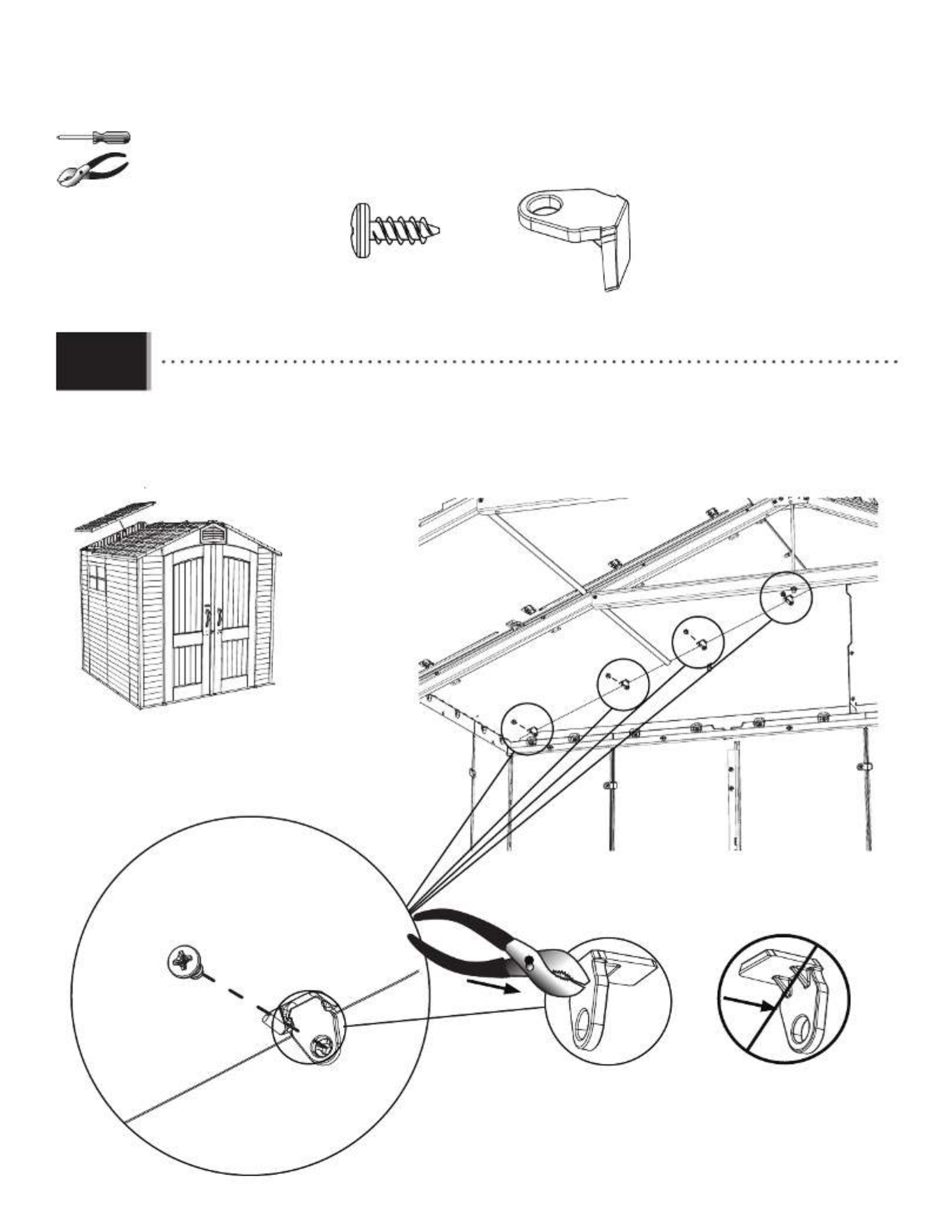
• Attach the at the top left corner of the Window. Latch (AIS) The Latch should move freely.
• Attachez le à l’angle supérieur gauche de la fenêtre. loquet (AIS) Le loquet doit se déplacer librement.
• Sujete el a la esquina izquierda superior de la ventana. cerrojo (AIS) El cerrojo debe mover libremente.

45
DOOR & ENTRY GABLE INSTALLATION / INSTALLATION DES PORTES ET DU PIGNON D’ENTRÉE /
INSTALACIÓN DE LAS PUERTAS Y LA FACHADA DE ENTRADA
9
AHP (x2) ADZ (x11)
ADX (x2)
BFY (x5)
BYB (x1)
AGF (x1)
AGO (x1)
7/16 in/po (11 mm)
AGZ (x1)
BYA (x1)
ADJ (x5) BXZ (x16)
BYM (x1)
70 7/8"
70 7/8 in/po (1,80 m)
72 in/po (1,83 m)
Metal Parts / /
Pièces en métal Piezas de metal
Plastic Parts / / Pièces en plastique Piezas de plástico
Hardware Bag / / Sac de quincaillerie Bolsa de herraje
TOOLS REQUIRED / OUTILS REQUIS / INSTRUMENTAL REQUERIDO
PARTS REQUIRED / PIÈCES REQUISES / PIEZAS REQUERIDAS
HARDWARE REQUIRED / QUINCAILLERIE REQUISE / HERRAJE REQUERIDO
FKP

46
TOOLS AND HARDWARE REQUIRED / / OUTILS ET QUINCAILLERIE REQUIS INSTRUMENTAL Y HERRAJE REQUERIDOS
X SECTION 9 (CONTINUED) / / SECTION 9 (SUITE) SECCIÓN 9 (CONTINUACIÓN)
ADZ (x6) BXZ (x6)
ADZ
ADZ
BXZ
BYB
BYB
• Place the , the wider of the two Right Door Jamb (BYB)
Jambs, onto the edge of the right, front Corner Wall
Panel. The Curved end curves toward the inside of
the shed. Align the holes in the Jamb with those in
the Corner Wall Panel. Secure the Jamb to the Panel
using six (6) . Screws (ADZ) The top hole does not require a
Screw—yet.
• Mettez le , le plus large des deux montant droit (BYB)
montants, sur le bord du panneau angulaire droit
avant. Le bord recourbé du montant courbe vers
l’intérieur de l’abri. Alignez les trous dans le montant
avec ceux du panneau angulaire. Attachez bien le
montant au panneau à l’aide de six (6) . vis (ADZ) Le
trou supérieur n’exige pas encore d’une vis.
• Coloque la , la más ancha de las jamba derecha (BYB)
dos jambas, en el borde del panel angular derecho
delantero. El borde curvado va hacia el interior de la
caseta. Alinee los agujeros en la jamba con ellos en
en panel angular. Sujete la jamba al panel usando
seis (6) . tornillos (ADZ) El agujero superior no requiere un
tornillo todavía.
• Curved edge
• Bord courbé
• Borde curvo
ADZ
ADZ
BXZ
BXZ
• If you have trouble with this section, follow the code below to
view a video on how to assemble this section.
• En cas d’avoir des problèmes avec cette section, suivre le code
en bas pour voir un vidéo sur l’assemblage de cette section.
• En caso de problemas con esta sección, seguir el código debajo
para ver un video sobre el ensamblaje de esta sección.
http://go.lifetime.com/7doorinstall
LIFETIME©
9.1

47
26 11/16”
26 11/16 in/po (67,79 cm)
AGR (x2)
AHD (x4) AHH (x2) AGL (x1)
AGQ (x2)
AHE (x2)
AFX (x1)
BYY (x6)
BYW (x2)
BYX (x4)
PARTS IDENTIFIER / IDENTIFICATEUR DE PIÈCES / IDENTIFICADOR DE PIEZAS
CONTENTS OF BOX 1 / / CONTENU DE LA BOÎTE 1 CONTENIDO DE LA CAJA 1
CONTENTS OF SMALL PARTS BOX / / CONTENU DE LA BOÎTE DE PETITES PIÈCES CONTENIDO DE LA CAJA DE PIEZAS PEQUEÑAS
Remove This Section for Quick Reference / pour référence rapide / Enlever cette section Reitirar esta sección para referencia rápida
ETD (x2)
BYS (x2)
BYR (x2) EUF (x1)
EUG (x4)
AFZ (x2)
AIY (x2)

48
AGL (x3)
AGO (x1) AGZ (x1)
AGQ (x4)
AGF (x1)
BYV (x1)
AGH (x1)
AGI (x1)
PARTS IDENTIFIER / IDENTIFICATEUR DE PIÈCES / IDENTIFICADOR DE PIEZAS
BLISTER PACKS / / BLISTERS BLÍSTERES
CONTENTS OF BOX 2 / / CONTENU DE LA BOÎTE 2 CONTENIDO DE LA CAJA 2
Remove This Section for Quick Reference / pour référence rapide / Enlever cette section Reitirar esta sección para referencia rápida
FRA FKP FRB FRD EVG FHF
AFS (x1)

49
75 in/po (1,91 m)
77 in/po (1,96 m)
CHH (x2)
CHI (x2)
PARTS IDENTIFIER / IDENTIFICATEUR DE PIÈCES / IDENTIFICADOR DE PIEZAS
CONTENTS METAL KIT / / CONTENU DU KIT DE PIÈCES EN MÉTAL CONTENIDO DEL KIT DE PIEZAS DE METAL
40 in/po (1,02 m)
72 in/po (1,83 m)
70 7/8"
70 7/8 in/po (1,80 m)
54 3/8”
54 3/8 in/po (1,38 m)
78 3/8”
78 3/8 in/po (1,99 m)
AFG (x2)
BYA (x1)
AFM (x4)
BXX (x1)
AFE (x1)
AFH (x4)
BYB (x1)
67 3/4 in/po (1,72 m)
43 1/4”43 1/4 in/po (1,10 m)
Remove This Section for Quick Reference / pour référence rapide / Enlever cette section Reitirar esta sección para referencia rápida
49” (1,25 m)
49 in/po (1,25 m)
BXT (x2)

50
PARTS IDENTIFIER / IDENTIFICATEUR DE PIÈCES / IDENTIFICADOR DE PIEZAS
Remove This Section for Quick Reference / pour référence rapide / Enlever cette section Reitirar esta sección para referencia rápida
THIS PAGE INTENTIONALLY LEFT BLANK
CETTE LPAGE A ÉTÉ INTENTIONNELLEMENT LAISSÉE EN BLANC
ESTA PÁGINA SE HA DEJADO EN BLANCO INTENCIONADAMENTE

51
TOOLS AND HARDWARE REQUIRED / /
OUTILS ET QUINCAILLERIE REQUIS INSTRUMENTAL Y HERRAJE REQUERIDOS
X SECTION 9 (CONTINUED) / / SECTION 9 (SUITE) SECCIÓN 9 (CONTINUACIÓN)
BFY (x5) ADJ (x5)
BXZ (x10)
BYA
BYA
7/16 in/po
(11 mm)
• Place the Left Door Jamb (BYA) onto the edge of the left, front Corner Wall Panel. The Curved edge curves toward the
outside of the shed. Align the holes in the Jamb with those in the Corner Wall Panel. Secure the Jamb to the Panel
using the hardware included.
• Mettez le montant gauche (BYA) sur le bord du panneau angulaire gauche avant. Le bord recourbé du montant
courbe vers l’extérieur de l’abri. Alignez les trous dans le montant avec ceux du panneau angulaire. Attachez bien
le montant au panneau à l’aide de la quincaillerie incluse.
• Coloque la jamba izquierda (BYA) en el borde del panel angular izquierdo delantero. El borde curvado va hacia el
exterior de la caseta. Alinee los agujeros en la jamba con ellos en panel angular. Sujete la jamba al panel usando el
herraje incluido.
• Curved edge
• Bord courbé
• Borde curvo
BXZ
BXZ
BXZ
BXZ ADJ
ADJ
BFY
BFY
9.2

53
TOOLS AND HARDWARE REQUIRED / / OUTILS ET QUINCAILLERIE REQUIS INSTRUMENTAL Y HERRAJE REQUERIDOS
X SECTION 9 (CONTINUED) / / SECTION 9 (SUITE) SECCIÓN 9 (CONTINUACIÓN)
ADZ (x5)
AGF
• Slide the holes in the Entry Gable down over the two Hinge Tubes.
• Glissez les trous dans le pignon d’entrée sur les deux tubes.
• Deslice los agujeros en la fachada de entrada sobre los dos tubos.
ADZ (x5)
• Secure the Entry Gable to the Shed using fi ve (5) .Screws (ADZ)
• Attachez le pignon d’entrée à l’abri à l’aide de cinq (5) .vis (ADZ)
• Sujete la fachada de entrada a la caseta usando cinco (5) .tornillos (ADZ)
9.5
9.6

54
TOOLS AND HARDWARE REQUIRED / /
OUTILS ET QUINCAILLERIE REQUIS INSTRUMENTAL Y HERRAJE REQUERIDOS
X SECTION 9 (CONTINUED) / / SECTION 9 (SUITE) SECCIÓN 9 (CONTINUACIÓN)
ADX (x2)
BYM (x1)
ADX
ADX
BYM
• Attach the to the fl oor as shown.strike Plate (BYM)
• Attachez la au plancher comme illustré.plaque de verrouillage (BYM)
• Sujete la al piso como se muestra.placa de cierre (BYM)
9.7

55
ROOF ASSEMBLY / ASSEMBLAGE DU TOIT / ENSAMBLAJE DEL TEJADO
10
Metal Parts / / Pièces en métal Piezas de metal
Plastic Parts / / Pièces en plastique Piezas de plástico
Hardware Bag / / Sac de quincaillerie Bolsa de herraje
TOOLS REQUIRED / OUTILS REQUIS / INSTRUMENTAL REQUERIDO
PARTS REQUIRED / PIÈCES REQUISES / PIEZAS REQUERIDAS
HARDWARE REQUIRED / QUINCAILLERIE REQUISE / HERRAJE REQUERIDO
26 11/16”
26 11/16 in/po (67,8 cm)
BYY (x6)
BYT (x16)
AGQ (x6)
BYV (x1)
BYW (x2)
BYX (x4)
x2
AGI (x1) AGH (x1)
ADV (x24)
ADZ (x86)
FRD

56
TOOLS AND HARDWARE REQUIRED / / OUTILS ET QUINCAILLERIE REQUIS INSTRUMENTAL Y HERRAJE REQUERIDOS
X SECTION 10 (CONTINUED) / / SECTION 10 (SUITE) SECCIÓN 10 (CONTINUACIÓN)
10.1
AGQ
BYY
Click!
Click!
• Insert a Support Tube (BYY) Roof Support Panel (AGQ) Repeat this step for all Roof Panels. into the notches of a .
• Insérez un dans les encoches du . tube de support (BYY) panneau de toit (AGQ) Répétez cette étape pour tous les panneaux de toit.
• Inserte un en la muescas del . tubo de soporte (BYY) panel de tejado (AGQ) Repita este paso para todos los paneles de tejado.
• If you have trouble with this section, follow the code below to view a video on how to assemble this section.
• En cas d’avoir des problèmes avec cette section, suivre le code en bas pour voir un vidéo sur l’assemblage de cette section.
• En caso de problemas con esta sección, seguir el código debajo para ver un video sobre el ensamblaje de esta sección.
http://go.lifetime.com/roofassembly7
LIFETIME
©

58
TOOLS AND HARDWARE REQUIRED / /
OUTILS ET QUINCAILLERIE REQUIS INSTRUMENTAL Y HERRAJE REQUERIDOS
X SECTION 10 (CONTINUED) / / SECTION 10 (SUITE) SECCIÓN 10 (CONTINUACIÓN)
10.4
10.5
ADZ (x5) ADV (x4)
ADV ADZ
• Insert four (4) long along the top edge of the Wall Panel and four (4) short along the Truss as Screws (ADV) Screws (ADZ)
shown.
• Insérez quatre (4) le long du bord supérieur du panneau mural et quatre (4) courtes à travers la vis (ADV) vis (ADZ)
ferme comme illustré.
• Inserte cuatro (4) largos a lo largo del borde superior del panel mural y cuatro (4) cortos a tornillos (ADV) tornillos (ADZ)
través de la cercha como se muestra.
BYT (x1)
BYT
ADZ
BYT
• Orient the bottom-most as shown in this image, and insert it into the location indicated.Clip (BYT)
• Orientez le le plus bas comme illustré dans cette image, et insérez-le dans l’emplacement indiqué.clip (BYT)
• Oriente el el más bajo como se muestra en esta imagen, e insértelo en la ubicación indicada.clip (BYT)

60
TOOLS AND HARDWARE REQUIRED / /
OUTILS ET QUINCAILLERIE REQUIS INSTRUMENTAL Y HERRAJE REQUERIDOS
X SECTION 10 (CONTINUED) / / SECTION 10 (SUITE) SECCIÓN 10 (CONTINUACIÓN)
ADV
ADZ
10.8
10.9
ADZ (x4) ADV (x4)
• Insert four (4) long along the top edge of the Wall Panel and four (4) short along the Truss as Screws (ADV) Screws (ADZ)
shown.
• Insérez quatre (4) le long du bord supérieur du panneau mural et quatre (4) courtes à travers la vis (ADV) vis (ADZ)
ferme comme illustré.
• Inserte cuatro (4) largos a lo largo del borde superior del panel mural y cuatro (4) cortos a tornillos (ADV) tornillos (ADZ)
través de la cercha como se muestra.
• Set a Truss Assembly into the notches on the second two opposite Wall Panels. Set a Roof Panel onto the Gable,
Wall Panel, and Truss Assembly.
• Mettez une ferme dans les encoches des premiers deux panneaux muraux opposés. Mettez un panneaux de toit
sur le toit à pignon, panneau mural, et la ferme.
• Coloque una cercha dentro de las muescas de los primeros dos paneles murales opuestos. Coloque un panel de
tejado sobre la fachada de entrada, panel mural, y la cercha.

61
TOOLS AND HARDWARE REQUIRED / / OUTILS ET QUINCAILLERIE REQUIS INSTRUMENTAL Y HERRAJE REQUERIDOS
X SECTION 10 (CONTINUED) / / SECTION 10 (SUITE) SECCIÓN 10 (CONTINUACIÓN)
ADZ (x8)
ADZ (x8)
ADV (x4)
ADV (x4)
10.10 • Set a Roof Panel onto the Gable, Wall Panel, and Truss Assembly, and secure it with the hardware shown. Only
insert the long Screws (ADV) along the top edge of the Wall Panel.
• Mettez un panneau de toit sur le toit à pignon, panneau mural, et la ferme, et attachez-le à l’aide des
accessoires illustrés. N’insérez les vis (ADV) courtes que le long du bord supérieur du panneau mural.
• Coloque un panel de tejado sobre la fachada de entrada, panel mural, y la cercha, y sujételo usando el
herraje indicado. Inserte los tornillos (ADV) largos sólo a lo largo del borde superior del panel mural.

62
TOOLS AND HARDWARE REQUIRED / / OUTILS ET QUINCAILLERIE REQUIS INSTRUMENTAL Y HERRAJE REQUERIDOS
X SECTION 10 (CONTINUED) / / SECTION 10 (SUITE) SECCIÓN 10 (CONTINUACIÓN)
10.11 • Repeat the last step for the opposite Roof Panel. Only insert the long Screws (ADV) along the top edge of the Wall Panel.
• Répétez l’étape précédente pour le panneau de toit opposé. N’insérez les vis (ADV) courtes que le long du bord supérieur du panneau
mural.
• Repita el paso anterior para el panel de tejado opuesto. Inserte los tornillos (ADV) largos sólo a lo largo del borde superior del panel
mural.
ADZ (x8) ADV (x4)
ADZ (x8)
ADV (x4)
64
TOOLS AND HARDWARE REQUIRED / / OUTILS ET QUINCAILLERIE REQUIS INSTRUMENTAL Y HERRAJE REQUERIDOS
X SECTION 10 (CONTINUED) / / SECTION 10 (SUITE) SECCIÓN 10 (CONTINUACIÓN)
AGQ
ADZ (x4)
BYT (x4)
10.13 • Set the Roof Panel onto the Gable, Wall Panel, and Truss Assembly. Orient the as shown in this Clips (BYT)
image, and insert them in the locations indicated.
• Mettez le panneau de toit sur le pignon, panneau mural, et la ferme. Orientez les comme illustré clips (BYT)
dans cette image, et insérez-les dans les emplacements indiqués.
• Coloque el panel de tejado sobre la fachada de entrada, panel mural, y la cercha. Oriente los como clips (BYT)
se muestra en esta imagen, e insértelos en las ubicaciones indicadas.
ADZ
Produkt Specifikationer
| Mærke: | Lifetime |
| Kategori: | Haveskur |
| Model: | 60042 |
| Bredde: | 2130 mm |
| Dybde: | 2130 mm |
| Højde: | - mm |
| Dørtype: | Dobbelt |
| Antal døre: | 1 dør(e) |
| Antal vinduer: | 1 |
| Tagtype: | A- rammetag |
| Integreret gulv: | Ja |
| Tagfarve: | Grå |
| Vægfarve: | Hvid |
| Indvendigt gulvareal: | - m² |
Har du brug for hjælp?
Hvis du har brug for hjælp til Lifetime 60042 stil et spørgsmål nedenfor, og andre brugere vil svare dig
Haveskur Lifetime Manualer

18 August 2024
Haveskur Manualer
Nyeste Haveskur Manualer
22 Januar 2023