Mini Hardtop (2014) Manual
Læs nedenfor 📖 manual på dansk for Mini Hardtop (2014) (230 sider) i kategorien auto. Denne guide var nyttig for 45 personer og blev bedømt med 4.5 stjerner i gennemsnit af 2 brugere
Side 1/230


MINI Owner's Manual for Vehicle
Thank you for choosing a MINI.
The more familiar you are with your vehicle, the better control
you will have on the road. We therefore strongly suggest:
Read this Owner's Manual before starting off in your new MINI.
Also use the Integrated Owner's Manual in your vehicle. It con‐
tains important information on vehicle operation that will help
you make full use of the technical features available in your
MINI. The manual also contains information designed to en‐
hance operating reliability and road safety, and to contribute to
maintaining the value of your MINI.
Any updates made after the editorial deadline can be found in
the appendix of the printed Owner's Handbook for the Vehicle.
Get started now. We wish you driving fun and inspiration with
your MINI
The MINI team of BMW AG
Online Edition for Part no. 01 40 2 927 905 - II/14

© 2014 Bayerische Motoren Werke
Aktiengesellschaft
Munich, Germany
Reprinting, including excerpts, only with the written
consent of BMW AG, Munich.
US English II/14, 03 14 490
Printed on environmentally friendly paper, bleached
without chlorine, suitable for recycling.
Online Edition for Part no. 01 40 2 927 905 - II/14
Contents
The fastest way to find information on a partic‐
ular topic or item is by using the index, refer to
page 220.
6Notes
AT A GLANCE
14 Cockpit
18 Onboard monitor
26 Voice activation system
29 Integrated Owner's Manual in the vehicle
CONTROLS
34 Opening and closing
47 Adjusting
55 Transporting children safely
59 Driving
71 Displays
86 Lamps
91 Safety
106 Driving stability control systems
110 Driving comfort
127 Climate control
133 Interior equipment
135 Digital compass
141 Storage compartments
DRIVING TIPS
148 Things to remember when driving
151 Loading
155 Saving fuel
MOBILITY
164 Refueling
166 Fuel
168 Wheels and tires
180 Engine compartment
182 Engine oil
185 Coolant
186 Maintenance
188 Replacing components
201 Breakdown assistance
207 Care
REFERENCE
214 Technical data
216 Appendix
218
Online Edition for Part no. 01 40 2 927 905 - II/14
220 Everything from A to Z
License Texts and Certifications

Notes
Using this Owner's
Manual
The fastest way to find information on a partic‐
ular topic is by using the index.
An initial overview of the vehicle is provided in
the first chapter.
Updates made after the editorial
deadline
Any updates made after the editorial deadline
for the Owner's Manuals are located in the ap‐
pendix of the printed quick reference for the
vehicle.
User's manual for Navigation,
Entertainment, Communication
The topics Navigation, Entertainment, Commu‐
nication and the short commands of the voice
activation system can be retrieved via the
Integrated Owner's Handbook.
Additional sources of information
Should you have any questions, your service
center will be glad to advise you at any time.
Information about MINI, e.g., on technology, is
available on the Internet: www.miniusa.com
Symbols
Indicates precautions that must be followed
precisely in order to avoid the possibility of
personal injury and serious damage to the
vehicle.
◄ Marks the end of a specific item of
information.
"..." Identifies Control Display texts used to
select individual functions.
›...‹ Verbal instructions to use with the voice
activation system..
››...‹‹ Identifies the answers generated by the
voice activation system.
Refers to measures that can be taken to
help protect the environment.
Vehicle equipment
This Owner's Manual describes all models and
all standard, country-specific and optional
equipment that is offered in the model series.
Therefore, in this Owner's Manual, equipment
is also described and illustrated that is not
available in your vehicle, e.g., because of the
selected optional equipment or the country-
specific variants.
This also applies for safety-related functions
and systems.
For any options and equipment not described
in this Owner's Handbook, refer to the Supple‐
mentary Owner's Handbooks.
On right-hand drive vehicles, some control ele‐
ments are arranged differently than shown in
the illustrations.
Status of the Owner's
Manual
Basic information
The manufacturer of your vehicle pursues a
policy of constant development that is con‐
ceived to ensure that our vehicles continue to
embody the highest quality and safety stan‐
dards. In rare cases, therefore, the features de‐
scribed in this Owner's Manual may differ from
those in your vehicle.
Seite 6
Notes
6Online Edition for Part no. 01 40 2 927 905 - II/14

Updates made after the editorial
deadline
Any updates made after the editorial deadline
can be found in the appendix of the printed
Owner's Handbook for Vehicle.
For your own safety
Manufacturer
The manufacturer of this MINI is Bayerische
Motoren Werke Aktionengesellschaft, BMW AG.
Warranty
Your vehicle is technically configured for the
operating conditions and registration require‐
ments applying in the country of first delivery -
homologation. If your vehicle is to be operated
in a different country it might be necessary to
adapt your vehicle to potentially differing oper‐
ating conditions and permit requirements. If
your vehicle does not comply with the homolo‐
gation requirements in a certain country you
cannot lodge warranty claims for your vehicle
there. Further information can be obtained
from your Service Centre.
Maintenance and repairs
Advanced technology, e.g., the use of modern
materials and high-performance electronics,
requires suitable maintenance and repair
methods.
Therefore, have this work performed only by a
MINI service center or a workshop that works
according to repair procedures of the manufac‐
turer of the MINI with appropriately trained
personnel.
If this work is not carried out properly, there is
the danger of subsequent damage and related
safety hazards.
Parts and accessories
MINI recommends using parts and accessories
approved by the manufacturer of the MINI for
this purpose.
Your MINI service center is the right contact for
genuine MINI parts and accessories, other
products approved by the manufacturer of the
MINI and related qualified advice.
The manufacturer of the MINI has tested these
products for safety and suitability in relation to
MINI vehicles.
The manufacturer of the MINI assumes respon‐
sibility for them. However, we cannot assume
any responsibility whatsoever for parts and ac‐
cessories that have not been specifically ap‐
proved by MINI.
MINI cannot evaluate whether each individual
product from another manufacturer can be
used with MINI vehicles without presenting a
safety hazard. This guarantee is also not appli‐
cable when country-specific government ap‐
proval has been granted. Testing of this kind
may fail to embrace the entire range of poten‐
tial operating conditions to which components
might be exposed on MINI vehicles. Such prod‐
ucts could conceivably fail to comply with
MINI's own stringent quality standards.
California Proposition 65 Warning
California laws require us to state the following
warning:
Engine exhaust and a wide variety of automo‐
bile components and parts, including compo‐
nents found in the interior furnishings in a vehi‐
cle, contain or emit chemicals known to the
State of California to cause cancer and birth de‐
fects and reproductive harm. In addition, cer‐
tain fluids contained in vehicles and certain
products of component wear contain or emit
chemicals known to the State of California to
cause cancer and birth defects or other repro‐
ductive harm. Battery posts, terminals and re‐
lated accessories contain lead and lead com‐
pounds. Wash your hands after handling. Used
Seite 7
Notes
7
Online Edition for Part no. 01 40 2 927 905 - II/14

engine oil contains chemicals that have caused
cancer in laboratory animals. Always protect
your skin by washing thoroughly with soap and
water.
Service and warranty
We recommend that you read this publication
thoroughly. Your vehicle is covered by the fol‐
lowing warranties:
▷New Vehicle Limited Warranty.
▷Rust Perforation Limited Warranty.
▷Federal Emissions System Defect Warranty.
▷Federal Emissions Performance Warranty.
▷California Emission Control System Limited
Warranty.
Detailed information about these warranties is
listed in the Service and Warranty Information
Booklet for US models or in the Warranty and
Service Guide Booklet for Canadian models.
Your vehicle has been specifically adapted and
designed to meet the particular operating con‐
ditions and homologation requirements in your
country and continental region in order to de‐
liver the full driving pleasure while the vehicle is
operated under those conditions. If you wish to
operate your vehicle in another country or re‐
gion, you may be required to adapt your vehi‐
cle to meet different prevailing operating con‐
ditions and homologation requirements. You
should also be aware of any applicable war‐
ranty limitations or exclusions for such country
or region. In such case, please contact Cus‐
tomer Relations for further information.
Maintenance
Maintain the vehicle regularly to sustain the
road safety, operational reliability and the New
Vehicle Limited Warranty.
Specifications for required maintenance meas‐
ures:
▷MINI Maintenance system
▷Service and Warranty Information Booklet
for US models
▷Warranty and Service Guide Booklet for
Canadian models
If the vehicle is not maintained according to
these specifications, this could result in serious
damage to the vehicle. Such damage is not
covered by the MINI New Vehicle Limited War‐
ranty.
Data memory
Many electronic components on your vehicle
are equipped with data memories that tempo‐
rarily or permanently store technical informa‐
tion about the condition of the vehicle, events
and faults. This technical information generally
documents the state of a component, a mod‐
ule, a system or the environment:
▷Operating states of system components, fill
levels for instance.
▷Status messages for the vehicle and from its
individual components, e.g., wheel rotation
speed/ vehicle speed, deceleration, trans‐
verse acceleration.
▷Malfunctions and faults in important system
components, e.g., lights and brakes.
▷Responses by the vehicle to special situa‐
tions, e.g., deployment of an airbag, en‐
gagement of stability control systems.
▷Ambient conditions, such as temperature.
This data is purely technical in nature and is
used to detect and correct faults and to opti‐
mize vehicle functions. Motion profiles over
routes traveled cannot be created from this
data. When service offerings are used, e.g., re‐
pair services, service processes, warranty
claims, quality assurance, this technical infor‐
mation can be read out from the event and
fault memories by the service personnel, in‐
cluding the manufacturer, using special diag‐
nostic tools. You can obtain further information
there if it is needed. After a fault is corrected,
the information in the fault memory is deleted
or overwritten on a continuous basis.
Seite 8
Notes
8Online Edition for Part no. 01 40 2 927 905 - II/14

When the vehicle is in use, situations are con‐
ceivable in which it might be possible to asso‐
ciate this technical data with individuals if it is
combined with other information, e.g., an acci‐
dent report, damage to the vehicle, eye witness
accounts — possibly with the assistance of an
expert.
Additional functions that are contractually
agreed with the customer, such as vehicle lo‐
cating in an emergency, enable certain vehicle
data to be transmitted from the vehicle.
Event Data Recorder EDR
This vehicle is equipped with an event data re‐
corder EDR. The main purpose of an EDR is to
record, in certain crash or near crash-like situa‐
tions, such as an air bag deployment or hitting
a road obstacle, data that will assist in under‐
standing how a vehicle’s systems performed.
The EDR is designed to record data related to
vehicle dynamics and safety systems for a short
period of time, typically 30 seconds or less.
The EDR in this vehicle is designed to record
such data as:
▷How various systems in your vehicle were
operating.
▷Whether or not the driver and passenger
safety belts were fastened.
▷How far, if at all, the driver was depressing
the accelerator and/or brake pedal.
▷How fast the vehicle was traveling.
These data can help provide a better under‐
standing of the circumstances in which crashes
and injuries occur.
EDR data are recorded by your vehicle only if a
nontrivial crash situation occurs; no data are re‐
corded by the EDR under normal driving condi‐
tions and no personal data, e.g., name, gender,
age, and crash location, are recorded.
However, other parties, such as law enforce‐
ment, could combine the EDR data with the
type of personally identifying data routinely ac‐
quired during a crash investigation.
To read data recorded by an EDR, special
equipment is required, and access to the vehi‐
cle or the EDR is needed. In addition to the ve‐
hicle manufacturer, other parties, such as law
enforcement, that have the special equipment,
can read the information if they have access to
the vehicle or the EDR.
Reporting safety defects
For US customers
The following only applies to vehicles owned
and operated in the US.
If you believe that your vehicle has a defect
which could cause a crash or could cause injury
or death, you should immediately inform the
National Highway Traffic Safety Administration
NHTSA, in addition to notifying MINI of North
America, LLC, P.O. Box 1227, Westwood, New
Jersey 07675-1227, Telephone
1-800-831-1117.
If NHTSA receives similar complaints, it may
open an investigation, and if it finds that a
safety defect exists in a group of vehicles, it
may order a recall and remedy campaign.
However, NHTSA cannot become involved in
individual problems between you, your dealer,
or MINI of North America, LLC.
To contact NHTSA, you may call the Vehicle
Safety Hotline toll-free at 1-888-327-4236
(TTY: 1-800-424-9153); go to http://www.safe‐
rcar.gov; or write to: Administrator, NHTSA, 400
Seventh Street, SW., Washington, DC 20590.
You can also obtain other information about
motor vehicle safety from http://www.safe‐
rcar.gov
For Canadian customers
Canadian customers who wish to report a
safety-related defect to Transport Canada, De‐
fect Investigations and Recalls, may telephone
Seite 9
Notes
9
Online Edition for Part no. 01 40 2 927 905 - II/14

the toll-free hotline 1-800-333-0510. You can
also obtain other information about motor ve‐
hicle safety from http://www.tc.gc.ca/roadsaf‐
ety.
Seite 10
Notes
10 Online Edition for Part no. 01 40 2 927 905 - II/14

Seite 11
Notes
11
Online Edition for Part no. 01 40 2 927 905 - II/14

WATCH ME.

AT A GLANCE
CONTROLS
DRIVING TIPS
MOBILITY
REFERENCE
Online Edition for Part no. 01 40 2 927 905 - II/14

Cockpit
Vehicle equipment
All standard, country-specific and optional
equipment that is offered in the model series is
described in this chapter. Therefore, equipment
is also described that is not available in a vehi‐
cle, e. g., because of the selected optional
equipment or country variant. This also applies
for safety-related functions and systems.
All around the steering wheel
1Power windows 44
2Exterior mirror operation 52
3Central locking system 39
4Lamps
Front fog lamps 89
Parking lamps 86
Low beams 86
Automatic headlamp con‐
trol 87
Daytime running lights 87
Instrument lighting 89
5Steering wheel buttons, left
Cruise control on/off, inter‐
rupt 110
Cruise control on/off, inter‐
rupt 116
Seite 14
AT A GLANCE Cockpit
14 Online Edition for Part no. 01 40 2 927 905 - II/14

Store speed
Resume speed 112, 117
Set speed 112, 116
Reduce distance 116
Increase distance 110
6Steering column stalk, left
Turn signal 64
High beams, head‐
lamp flasher 64
Roadside parking lamps 86
Computer 79
7Instrument cluster 71
8Steering column stalk, right
Windshield wipers 64
Rain sensor 65
Cleaning windows 66
Rear window wiper 66
Cleaning rear window 66
9Steering wheel buttons, right
Voice activation 26
Telephone
Confirm the selection 78
Move selection up 78
Move selection down 78
Increase volume
Reduce volume
10 Horn
11 Adjust the steering wheel 54
12 Unlock hood 180
Seite 15
Cockpit AT A GLANCE
15
Online Edition for Part no. 01 40 2 927 905 - II/14

All around the center console
1Headliner 17
2Hazard warning system 201
Intelligent Safety 99
3Control Display 18
4Radio/Multimedia
5Glove compartment 141
6Climate control 127
7PDC Park Distance Control 118
Rearview camera 120
Parking assistant 122
Auto Start/Stop function 61
Start/stop the engine and switch
the ignition on/off 62
DSC Dynamic Stability Con‐
trol 106
Head-up Display 83
8Automatic transmission selector lever 67
Manual transmission selector lever 67
9Controller with buttons 18
10 Parking brake 63
11 Driving Dynamics Control 108
Seite 16
AT A GLANCE Cockpit
16 Online Edition for Part no. 01 40 2 927 905 - II/14

Onboard monitor
Vehicle equipment
All standard, country-specific and optional
equipment that is offered in the model series is
described in this chapter. Therefore, equipment
is also described that is not available in a vehi‐
cle, e. g., because of the selected optional
equipment or country variant. This also applies
for safety-related functions and systems.
The concept
The onboard monitor combines the functions
of a multitude of switches. Thus, these func‐
tions can be operated from a central location.
Using the onboard monitor during a trip
To avoid becoming distracted and posing
an unnecessary hazard to your vehicle's occu‐
pants and to other road users, never attempt to
use the controls or enter information unless
traffic and road conditions allow this.◀
Controls at a glance
Control elements
1Control Display
2Controller with buttons and, depending on
the equipment version, with touchpad
Control Display
Hints
▷To clean the Control Display, follow the care
instructions.
▷Do not place objects close to the Control
Display; otherwise, the Control Display can
be damaged.
Switching off
1. Press the button.
2. "Switch off control display"
Switching on
Press the controller again to switch the screen
back on.
Controller with navigation system
The buttons can be used to open the menus di‐
rectly. The controller can be used to select
menu items and create the settings.
Some functions of the onboard monitor can be
operated using the touchpad on the controller:
Seite 18
AT A GLANCE Onboard monitor
18 Online Edition for Part no. 01 40 2 927 905 - II/14

1. Turn.
2. Press.
3. Move in four directions.
Buttons on controller
Press the button Function
MENU Open the main menu.
RADIO Opens the Radio menu.
MEDIA Opens the Multimedia menu.
NAV Opens the Navigation menu.
TEL Opens the Telephone menu.
Press the button Function
BACK Displays the previous panel.
OPTION Opens the Options menu.
Controller without navigation system
The buttons can be used to open the menus di‐
rectly. The controller can be used to select
menu items and create the settings.
1. Turn.
2. Press.
3. Move in two directions.
Seite 19
Onboard monitor AT A GLANCE
19
Online Edition for Part no. 01 40 2 927 905 - II/14

Buttons on controller
Press the button Function
MENU Open the main menu.
Audio Open audio menu last listened
to, switch between audio me‐
nus.
TEL Opens the Telephone menu.
BACK Open previous panel.
OPTION Opens the Options menu.
Operating concept
Opening the main menu
Press the button.
The main menu is displayed.
All onboard monitor functions can be called up
via the main menu.
Selecting menu items
Highlighted menu items can be selected.
1. Turn the controller until the desired menu
item is highlighted.
2. Press the controller.
Menu items in the Owner's Manual
In the Owner's Manual, menu items that can be
selected are set in quotation marks, e.g.,
"Settings".
Changing between panels
After a menu item is selected, e.g., "Radio", a
new panel is displayed. Panels can overlap.
▷Move the controller to the left.
The current panel is closed and the previ‐
ous panel is displayed.
The previous panel is opened again by
pressing the BACK button. In this case, the
current panel is not closed.
▷Move the controller to the right.
A new panel is opened on top of the previ‐
ous display.
Seite 20
AT A GLANCE Onboard monitor
20 Online Edition for Part no. 01 40 2 927 905 - II/14

Arrows pointing to the left or right indicate that
additional panels can be opened.
View of an opened menu
When a menu is opened, it generally opens
with the panel that was last selected in that
menu. To display the first panel of a menu:
▷Move the controller to the left repeatedly
until the first panel is displayed.
▷Press the menu button on the controller
twice.
Opening the Options menu
Press the button.
The "Options" menu is displayed.
Additional options: move the controller to the
right repeatedly until the "Options" menu is
displayed.
Options menu
The "Options" menu consists of various areas:
▷Screen settings, e.g., "Split screen".
This area remains unchanged.
▷Control options for the selected main
menu, e.g., for "Radio".
▷If applicable, further operating options for
the selected menu, e.g., "Store station".
Changing settings
1. Select a field.
2. Turn the controller until the desired setting
is displayed.
3. Press the controller.
Activating/deactivating the functions
Several menu items are preceded by a check‐
box. It indicates whether the function is acti‐
vated or deactivated. Selecting the menu item
activates or deactivates the function.
The function is activated.
The function is deactivated.
Touchpad
Some functions of the onboard monitor can be
operated using the touchpad on the controller:
Selecting functions
1. "Settings"
2. "Touchpad"
3. Select the desired function.
▷"Speller": enter letters and numbers.
▷"Interactive map": operating the inter‐
active map.
▷"Audio feedback": the entered letters
and numbers are announced.
Entering letters and numbers
The entry of the letters requires some practice
at the beginning. In the entry, pay attention to
the following:
Seite 21
Onboard monitor AT A GLANCE
21
Online Edition for Part no. 01 40 2 927 905 - II/14

▷For the input of upper/lower case letters
and numbers, it may be necessary to switch
via the controller to the corresponding In‐
put mode, refer to page 25, e.g. when the
spelling of upper and lower case letters is
identical.
▷Enter characters as they are displayed on
the Control Display.
▷Always enter accompanying signs, such as
accents or periods so that the letter can be
clearly recognized. The possibility of input
depends on the set language. Where nec‐
essary, enter special characters via the con‐
troller.
▷To delete a character, slide to the left on
the touchpad.
▷To enter a blank space, slide to the right in
the center of the touchpad.
▷To enter a hyphen, slide to the right in the
upper area of the touchpad.
▷To enter an underscore, slide to the right in
the lower area of the touchpad.
Operating the interactive map
The interactive map in the navigation system
can be moved via the touchpad.
Function Controls
Interactive map. Slide in the corresponding
direction.
Enlarge/shrink in‐
teractive map.
Drag inwards or outwards
on the touchpad with the
fingers.
Display menu. Tap once.
Changing settings
Settings on the control display, such as the vol‐
ume, can be made via the touchpad. To do this
slide to the left or right accordingly.
Example: setting the
clock
Setting the clock
1. Press the button. The main menu is
displayed.
2. Turn the controller until "Settings" is high‐
lighted, and then press the controller.
3. If necessary, move the controller to the left
to display "Time/Date".
4. Turn the controller until "Time/Date" is
highlighted, and then press the controller.
5. Turn the controller until "Time:" is high‐
lighted, and then press the controller.
6. Turn the controller to set the hours and
press the controller.
7. Turn the controller to set the minutes and
press the controller.
Seite 22
AT A GLANCE Onboard monitor
22 Online Edition for Part no. 01 40 2 927 905 - II/14

Status information
Status field
The following information is displayed in the
status field at the top right:
▷Time.
▷Current entertainment source.
▷Sound output, on/off.
▷Wireless network reception strength.
▷Telephone status.
▷Traffic bulletin reception.
Status field symbols
The symbols are grouped as follows.
Radio symbols
Symbol Meaning
Satellite radio is switched on.
Telephone symbols
Symbol Meaning
Incoming or outgoing call.
Missed call.
Wireless network reception strength.
Symbol flashes: network search.
Wireless network is not available.
Bluetooth is switched on.
Roaming is active.
Text message was received.
Check the SIM card.
SIM card is blocked.
SIM card is missing.
Enter the PIN.
Entertainment symbols
Symbol Meaning
DVD changer.
Music collection.
Gracenote® database.
AUX-IN port.
USB audio interface.
Mobile phone audio interface.
Additional symbols
Symbol Meaning
Spoken instructions are switched off.
Split screen
General information
Additional information can be displayed on the
right side of the split screen, e.g., information
from the onboard computer.
In the divided screen view, the so-called split
screen, this information remains visible even
when you change to another menu.
Switching the split screen on and off
1. Press the button.
2. "Split screen"
Selecting the display
1. Press the button.
2. "Split screen"
3. Move the controller until the split screen is
selected.
Seite 23
Onboard monitor AT A GLANCE
23
Online Edition for Part no. 01 40 2 927 905 - II/14

4. Press the controller or select "Split screen
content".
5. Select the desired menu item.
Programmable memory
buttons
General information
The onboard monitor functions can be stored
on the programmable memory buttons and
called up directly, e.g., radio stations, naviga‐
tion destinations, phone numbers and entry
points into the menu.
The settings are stored for the remote control
currently in use.
Saving a function
1. Highlight function via the onboard monitor.
2. Press the desired button for more
than 2 seconds.
Running a function
Press the button.
The function will run immediately. This
means, for example, that the number is dialed
when a phone number is selected.
Displaying the button assignment
Use a finger to touch the buttons. Do not wear
gloves or use objects.
The key assignment is displayed at the top
edge of the screen.
▷To display short information: touch the but‐
ton.
▷To display detailed information: touch the
button for an extended period.
Deleting the button assignments
1. Press buttons 1 and 6 simultaneously for
approx. five seconds.
2. "OK"
Entering letters and
numbers
General information
1. Turn the controller: select letters or num‐
bers.
2. Select additional letters or numbers if
needed.
3. "OK": confirm the entry.
Symbol Function
Press the controller: delete the letter
or number.
Press the controller for an extended
period: delete all letters or numbers.
Seite 24
AT A GLANCE Onboard monitor
24 Online Edition for Part no. 01 40 2 927 905 - II/14

Switching between cases, letters and
numbers
Depending on the menu, you can switch be‐
tween entering upper and lower case, letters
and numbers:
Symbol Function
Enter the letters.
Enter the numbers.
or Move the controller up.
Without navigation system
Select the symbol.
Entry comparison
Entry of names and addresses: the selection is
narrowed down every time a letter is entered
and letters may be added automatically.
The entries are continuously compared to the
data stored in the vehicle.
▷Only those letters are offered during the
entry for which data is available.
▷Destination search: town/city names can be
entered using the spelling of language
available on the Control Display.
Seite 25
Onboard monitor AT A GLANCE
25
Online Edition for Part no. 01 40 2 927 905 - II/14

Voice activation system
Vehicle equipment
All standard, country-specific and optional
equipment that is offered in the model series is
described in this chapter. Therefore, equipment
is also described that is not available in a vehi‐
cle, e. g., because of the selected optional
equipment or country variant. This also applies
for safety-related functions and systems.
The concept
▷Most functions that are displayed on the
Control Display can be operated by spoken
commands via the voice activation system.
The system prompts you to make your en‐
tries.
▷Functions that can only be used when the
vehicle is stationary cannot be operated us‐
ing the voice activation system.
▷The system uses a special microphone on
the driver's side.
▷›...‹ Verbal instructions in the Owner's
Manual to use with the voice activation sys‐
tem.
Requirements
Via the Control Display, set a language that is
also supported by the voice activation system
so that the spoken commands can be identi‐
fied.
Set the language, refer to page 82.
Using voice activation
Activating the voice activation system
1. Press the button on the steering
wheel.
2. Wait for the signal.
3. Say the command.
The command is displayed in the instru‐
ment cluster.
This symbol in the instrument cluster indi‐
cates that the voice activation system is active.
If no other commands are available, operate
the function in this case via the onboard moni‐
tor.
Terminating the voice activation
system
Briefly press the button on the steering
wheel or ›End‹.
Possible commands
Most menu items on the Control Display can be
voiced as commands.
The available commands depend on which
menu is currently displayed on the Control Dis‐
play.
Short commands exist for many functions.
Some list entries, e.g., Phone book entries, can
also be selected via the voice activation system.
Speak these list entries exactly as they are dis‐
played in the respective list.
Having possible commands read aloud
You can have the available commands read out
loud for you: ›commands‹
Seite 26
AT A GLANCE Voice activation system
26 Online Edition for Part no. 01 40 2 927 905 - II/14

For example, if the "Settings" menu is dis‐
played, the commands for the settings are read
out loud.
Executing functions using short
commands
Functions on the main menu can be performed
directly by means of short commands, nearly ir‐
respective of which menu item is currently se‐
lected, e.g., ›Vehicle status‹.
Help dialog for the voice activation
system
Calling up help dialog: ›Help‹
Additional commands for the help dialog:
▷›Help with examples‹: information about
the current operating options and the most
important commands for them are an‐
nounced.
▷›Help voice activation‹: information about
the principle of operation for the voice acti‐
vation system is announced.
One example: open the
tone settings
Via the main menu
The commands of the menu items are spoken
just as they are selected via the controller.
1. Switch on the Entertainment sound output
if necessary.
2. Press the button on the steering
wheel.
3. ›Radio menu‹
4. ›Audio settings‹
Via short command
The desired radio station can also be started via
a short command.
1. Switch on the Entertainment sound output
if necessary.
2. Press the button on the steering
wheel.
3. ›Audio settings‹
Setting the voice dialog
You can set whether the system should use the
standard dialog or a shorter version.
In the shorter variant of the voice dialog, the
announcements from the system are issued in
an abbreviated form.
On the Control Display:
1. "Settings"
2. "Language/Units"
3. "Speech type:"
4. Select the setting.
Setting the voice dialog
language
You can set the language in which the voice ac‐
tivation and system announcements are to be
made.
On the Control Display:
1. "Settings"
2. "Language/Units"
3. "Speech type:"
4. Select the desired language.
Seite 27
Voice activation system AT A GLANCE
27
Online Edition for Part no. 01 40 2 927 905 - II/14

Adjusting the volume
Turn the volume button while giving an instruc‐
tion until the desired volume is set.
▷The volume remains constant even if the
volume of other audio sources is changed.
▷The volume is stored for the remote control
currently in use.
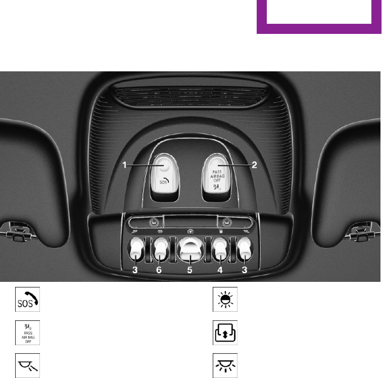
Hints on Emergency Re‐
quests
Do not use the voice activation system to ini‐
tiate an Emergency Request. In stressful situa‐
tions, the voice and vocal pitch can change.
This can unnecessarily delay the establishment
of a telephone connection.
Instead, use the SOS button, refer to page 201,
in the vicinity of the interior mirror.
Environmental condi‐
tions
▷Say the commands, numbers, and letters
smoothly and with normal volume, empha‐
sis, and speed.
▷Always say commands in the language of
the voice activation system.
▷Keep the doors, windows, and glass sun‐
roof closed to prevent noise interference.
▷Avoid making other noise in the vehicle
while speaking.
Seite 28
AT A GLANCE Voice activation system
28 Online Edition for Part no. 01 40 2 927 905 - II/14

Integrated Owner's Manual in the
vehicle
Vehicle equipment
All standard, country-specific and optional
equipment that is offered in the model series is
described in this chapter. Therefore, equipment
is also described that is not available in a vehi‐
cle, e. g., because of the selected optional
equipment or country variant. This also applies
for safety-related functions and systems.
Integrated Owner's
Manual in the vehicle
The Integrated Owner's Manual can be dis‐
played on the Control Display. The equipment
and functions that are in the vehicle are descri‐
bed therein.
Components of the Integrated Owner's
Manual
The Integrated Owner's Manual consists of
three parts, which offer various levels of infor‐
mation or access possibilities.
Quick Reference Guide
Located in the Quick Reference is important in‐
formation for the operation of the vehicle, the
operation of basic vehicle functions or for what
to do in the event of a flat tire. This information
can also be displayed during driving.
Search by pictures
Information and descriptions based on illustra‐
tions can be searched via search by pictures.
This is helpful, for example, if the description of
an outfitting package that cannot be named is
needed.
Owner's Manual
Information and descriptions can be searched
by direct entry of a search term via the index.
Select components
1. Press the button.
2. Turn the controller: open "Vehicle Info".
3. Press the controller.
4. Selecting desired range:
▷"Quick reference"
▷"Search by pictures"
▷"Owner's Manual"
Leafing through the Owner's Manual
Page by page with link access
Turn the controller until the next or previous
page is displayed.
Page by page without link access
Leaf through the pages directly while skipping
the links.
Highlight the symbol once. Now simply press
the controller to leaf from page to page.
Leaf back.
Seite 29
Integrated Owner's Manual in the vehicle AT A GLANCE
29
Online Edition for Part no. 01 40 2 927 905 - II/14

Leaf forward.
Context help - Owner's Manual to the
temporarily selected function
The relevant information can be opened di‐
rectly.
Opening via the onboard monitor
To move directly from the application on the
Control Display to the options menu:
1. Press the button or move the control‐
ler to the right repeatedly until the
"Options" menu is displayed.
2. "Display Owner's Manual"
Opening when a Check Control
message is displayed
Directly from the Check Control message on the
Control Display:
"Display Owner's Manual"
Changing between a function and the
Owner's Manual
To change from a function, e.g., radio, to the
Owner's Manual on the Control Display and to
switch between the two displays:
1. Press the button or move the control‐
ler to the right repeatedly until the
"Options" menu is displayed.
2. "Display Owner's Manual"
3. Select the desired page in the Owner's
Manual.
4. Press the button again to return to
the function displayed last.
5. Press the button to return to the page
of the Owner's Manual displayed last.
To switch back and forth repeatedly between
the function displayed last and the page of the
Owner's Manual displayed last, repeat steps 4
and 5. This opens a new panel every time.
Programmable memory buttons
General information
The Owner's Manual can be stored on the pro‐
grammable memory buttons and called up di‐
rectly.
Storing
1. "Owner's Manual" Select via the iDrive.
2. Press the desired button for more
than 2 seconds.
Executing
Press the button.
The Owner's Manual is displayed im‐
mediately.
Seite 30
AT A GLANCE Integrated Owner's Manual in the vehicle
30 Online Edition for Part no. 01 40 2 927 905 - II/14

Seite 31
Integrated Owner's Manual in the vehicle AT A GLANCE
31
Online Edition for Part no. 01 40 2 927 905 - II/14

HANDLE ME.

AT A GLANCE
CONTROLS
DRIVING TIPS
MOBILITY
REFERENCE
Online Edition for Part no. 01 40 2 927 905 - II/14

Opening and closing
Vehicle equipment
All standard, country-specific and optional
equipment that is offered in the model series is
described in this chapter. Therefore, equipment
is also described that is not available in a vehi‐
cle, e. g., because of the selected optional
equipment or country variant. This also applies
for safety-related functions and systems.
Remote control/key
General information
The vehicle is supplied with two remote con‐
trols with integrated keys.
Every remote control contains a replaceable
battery.
Depending on the equipment package and
country-specific variant, the functions of the
keys can be set. Settings, refer to page 42.
For every remote control, personal settings are
stored in the vehicle. Personal Profile, refer to
page 35.
Information on the required maintenance is
stored in the remote controls. Service data in
the remote control, refer to page 186
At a glance
1Unlocking
2Locking
3Unlock the tailgate
4Panic mode
Integrated key
Press the button on the remote control, ar‐
row 1, and pull out the key, arrow 2.
The integrated key fits the driver's door lock.
Replacing the battery
1. Take the integrated key out of the remote
control.
2. Slide the key into the opening and raise the
cover, arrow.
The battery compartment is accessible.
Seite 34
CONTROLS Opening and closing
34 Online Edition for Part no. 01 40 2 927 905 - II/14

3. Slide the key in the cover of the battery
compartment and raise the cover, arrow.
4. Insert a battery of the same type with the
positive side facing upwards.
5. Insert cap and cover.
Take the used battery to a recycling
center or to your service center.
New remote controls
New remote controls are available from the
service center.
Loss of the remote controls
Lost remote controls can be blocked by your
service center.
Emergency detection of remote control
It is possible to switch on the ignition or start
the engine in situations such as the following:
▷Interference of radio transmission to re‐
mote control by external sources, e.g. by
radio masts.
▷Discharged battery in the remote control.
▷Interference of radio transmission by mo‐
bile devices in close proximity to the re‐
mote control.
▷Interference of radio transmission by
charger while charging items such as mo‐
bile devices in the vehicle.
A Check Control message is displayed if an at‐
tempt is made to switch on the ignition or start
the engine.
Starting the engine via emergency
detection of the remote control
Automatic transmission: if a corresponding
Check Control message appears, hold the re‐
mote control, as shown, against the marked
area on the steering column and press the
Start/Stop button within 10 seconds while
pressing the brake.
Manual transmission: if a corresponding Check
Control message appears, hold the remote con‐
trol, as shown, against the marked area on the
steering column and press the Start/Stop but‐
ton within 10 seconds while pressing the
clutch.
Personal Profile
The concept
Individual settings in the vehicle are saved in
personal profiles. Every remote control is as‐
signed a profile.
▷Three personal profiles and a guest profile
can be created.
▷Changes to the settings are automatically
saved in the profile currently activated.
▷During unlocking, the profile stored for the
remote control is activated.
▷Your personal settings will be recognized
and called up again even if the vehicle has
been operated in the meantime with an‐
other remote control.
Seite 35
Opening and closing CONTROLS
35
Online Edition for Part no. 01 40 2 927 905 - II/14

Adjusting
The following settings are stored in a profile.
▷Radio: stored stations, station listened to
last.
▷Assignment of the programmable memory
buttons.
▷Tone settings.
▷Audio source listened to last.
▷Unlocking the vehicle: driver door or entire
vehicle.
▷Locking the vehicle: if no door is open or af‐
ter starting off.
▷Welcome lamps: on/off.
▷Triple turn signal activation: on/off.
▷Headlamp courtesy delay feature: time set‐
ting.
▷Language on the Control Display.
▷Daytime running lights: on/off.
▷Air conditioner/Automatic climate control:
settings.
▷Navigation: map views, route criteria, voice
output on/off.
▷Park Distance Control PDC: signal tone vol‐
ume.
▷Rearview camera: selection of functions
and type of display.
▷Head-up Display: selection, brightness, po‐
sition and rotation of the display.
▷Driving Dynamics Control: configuration.
Profile management
Opening the profiles
A different profile can be called up than the one
associated with the remote control currently in
use.
1. "Settings"
2. "Profiles"
3. Select a profile.
Called up profile is assigned to the remote con‐
trol being used at the time.
Renaming profiles
1. "Settings"
2. "Profiles"
The current profile is selected.
3. Open "Options".
4. "Rename current profile"
Resetting profiles
The settings of the active profile are reset to
their default values.
1. "Settings"
2. "Profiles"
The current profile is selected.
3. Open "Options".
4. "Reset current profile"
Importing profiles
Profiles stored on a USB device can be im‐
ported via the USB interface.
Existing settings and contacts are overwritten
with the imported profile.
1. "Settings"
2. "Profiles"
3. "Import profile"
4. "USB device"
Exporting profiles
Most settings of the active profile and the
saved contacts can be exported.
This can be helpful for securing and retrieving
personal settings, before delivering the vehicle
to a workshop for example. The saved profiles
can be taken with you to another vehicle
equipped with the Personal Profile function.
1. "Settings"
2. "Profiles"
Seite 36
CONTROLS Opening and closing
36 Online Edition for Part no. 01 40 2 927 905 - II/14

3. "Export profile"
4. "USB device"
Using the guest profile
The guest profile can be used to make individ‐
ual settings that are saved in none of the three
personal profiles.
This can be useful for drivers who are using the
vehicle temporarily and do not have their own
profile.
1. "Settings"
2. "Profiles"
3. Open "Guest".
4. Adjust the settings.
The guest profile cannot be renamed. It is not
assigned to the current remote control.
Display profile list during start
The profile list can be displayed during each
start for selecting the desired profile.
1. "Settings"
2. "Profiles"
3. Open "Options".
4. "Display user list at startup"
Opening and closing
Using the remote control
Note
Take the remote control with you
People or animals left unattended in a
parked vehicle can lock the doors from the in‐
side. Always take the remote control with you
when leaving the vehicle so that the vehicle
can then be opened from the outside.◀
Unlocking
Press the button on the remote con‐
trol.
The vehicle is unlocked.
Welcome lamps, interior lamp and courtesy
lamps are switched on.
Press the button on the remote control
twice.
When the door is opened, the window is low‐
ered to make it easier to enter the vehicle.
Depending on the equipment version and
country variant, you can set how the vehicle is
to be unlocked. Settings, refer to page 42.
The alarm system, refer to page 42, is dis‐
armed.
Convenient opening
The remote control can be used to open the
windows and the glass sunroof after unlocking.
Press and hold the button on the re‐
mote control.
Releasing the button stops the motion.
Locking
Press the button on the remote con‐
trol.
Locking from the outside
Do not lock the vehicle from the outside if
there are people in it, as the vehicle cannot be
unlocked from inside without special knowl‐
edge.◀
The alarm system, refer to page 42, is armed.
Switching on interior lamps and
courtesy lamps
Press the button on the remote control
with the vehicle locked.
Seite 37
Opening and closing CONTROLS
37
Online Edition for Part no. 01 40 2 927 905 - II/14

If the button is pressed within 10 seconds of
when the vehicle was locked Interior motion
sensor and tilt alarm sensor of the anti-theft
warning system, refer to page 43, are
switched off. After locking, wait 10 seconds be‐
fore pressing the button again.
Panic mode
You can trigger the alarm system if you find
yourself in a dangerous situation.
Press the button on the remote control
for at least 3 seconds.
To switch off the alarm: press any button.
Unlock the tailgate
Press the button on the remote control
for approx. 1 second.
The tailgate opens a little, regardless of
whether it was previously locked or unlocked.
Depending on the version and the country var‐
iant, it is possible to set whether the doors are
also unlocked. Settings, refer to page 42.
Do not place the remote control in the
cargo area
Take the remote control with you and do not
leave it in the cargo area; otherwise, the re‐
mote control is locked inside the vehicle when
the tailgate is closed.◀
The tailgate is locked again as soon as it is
pushed closed.
Provide edge protection
Sharp or angular objects can hit the rear
window while driving and damage the heating
wires of the rear window. Provide edge protec‐
tion.◀
Malfunction
If the vehicle can no longer be locked or un‐
locked with the remote control, the battery
may be discharged or there may be interfer‐
ence from external sources such as mobile
phones, metal objects, overhead power lines,
transmission towers, etc.
If this occurs, lock or unlock the driver's door at
the door lock using the integrated key.
For US owners only
The transmitter and receiver units comply with
part 15 of the FCC/Federal Communication
Commission regulations. Operation is governed
by the following:
FCC ID:
▷LX8766S.
▷LX8766E.
▷LX8CAS.
▷LX8CAS2.
▷MYTCAS4.
Compliance statement:
This device complies with part 15 of the FCC
Rules. Operation is subject to the following two
conditions:
▷This device may not cause harmful interfer‐
ence, and
▷this device must accept any interference re‐
ceived, including interference that may
cause undesired operation.
Any unauthorized modifications or changes to
these devices could void the user's authority to
operate this equipment.
Without remote control
From the outside
Locking from the outside
Do not lock the vehicle from the outside if
there are people in it, as the vehicle cannot be
unlocked from inside without special knowl‐
edge.◀
Seite 38
CONTROLS Opening and closing
38 Online Edition for Part no. 01 40 2 927 905 - II/14

Unlock or lock the driver's door via the door
lock using the integrated key.
To do this, unlock the cap from below with the
integrated key, arrow, and remove.
The state of the driver's door, tailgate and fuel
filler flap does not change.
Remove the key before pulling the door
handle
Before pulling the outside door handle, remove
the key to avoid damaging the paintwork and
the key.◀
Alarm system
The alarm system is not armed if the vehicle is
locked with the integrated key.
The alarm system is triggered when the door is
opened, if the vehicle was unlocked via the
door lock. In order to terminate this alarm, un‐
lock vehicle with the remote control or switch
on the ignition, if necessary, by emergency de‐
tection of the remote control.
From the inside
Locking and unlocking
Press the button.
The doors and the tailgate are locked.
The fuel filler flap is not locked.
Press the button.
The doors and the tailgate are un‐
locked.
In the event of an accident of corresponding
severity, the vehicle is automatically unlocked.
The hazard warning system and interior lamps
come on.
Unlocking and opening
Either unlock the doors together using the cen‐
tral locking system buttons and then pull the
door handle above the armrest or pull the door
handle on the door to be opened. The other
doors remain locked.
When there is an electrical defect
From the inside
Lock the doors via the door locking knobs.
Unlock and open the doors using the door un‐
locking handle.
Unlock the fuel filler flap via emergency unlock‐
ing. The state of the tailgate cannot be
changed in this case.
From the outside
Lock and unlock the driver's door lock using the
integrated key.
Tailgate
Opening
When the tailgate is opened, make sure there is
sufficient clearance to prevent damage.
Seite 39
Opening and closing CONTROLS
39
Online Edition for Part no. 01 40 2 927 905 - II/14

▷Unlock the vehicle and press the button on
the tailgate.
▷Press the button on the remote
control for approx. 1 second.
Depending on the version and the country
variant, it is possible to set whether the
doors are also unlocked. Settings, refer to
page 42.
The tailgate opens somewhat.
Pull the tailgate up to open.
Closing
Recessed grips on the inside trim of the tailgate
can be used to conveniently pull down the tail‐
gate.
Keep the closing path clear
Make sure that the closing path of the
trunk lid is clear; otherwise, injuries may re‐
sult.◀
Do not place the remote control in the
cargo area
Take the remote control with you and do not
leave it in the cargo area; otherwise, the re‐
mote control is locked inside the vehicle when
the tailgate is closed.◀
Provide edge protection
Sharp or angular objects can hit the rear
window while driving and damage the heating
wires of the rear window. Provide edge protec‐
tion.◀
Comfort Access
The concept
The vehicle can be accessed without activating
the remote control.
All you need to do is to have the remote control
with you, e.g., in your jacket pocket.
The vehicle automatically detects the remote
control when it is nearby or in the passenger
compartment.
Comfort Access supports the following func‐
tions:
▷Unlocking/locking of the vehicle.
▷Convenient closing.
▷Unlocking of the tailgate separately.
▷Start the engine.
Functional requirements
▷There are no sources of interference
nearby.
▷To lock the vehicle, the remote control
must be located outside of the vehicle.
▷The next unlocking and locking cycle is not
possible until after approx. 2 seconds.
▷The engine can only be started if the re‐
mote control is in the vehicle.
Seite 40
CONTROLS Opening and closing
40 Online Edition for Part no. 01 40 2 927 905 - II/14

Unlocking
On the driver's or front passenger's door han‐
dle, press the button, arrow.
This corresponds to pressing the remote control
button:
Locking
On the driver's or front passenger's door han‐
dle, press the button, arrow.
This corresponds to pressing the remote control
button:
To save battery power, ensure that all power
consumers are switched off before locking the
vehicle.
Convenient closing
Press and hold down the handle of the driver or
the front seat passenger.
This corresponds to pressing the remote control
button:
In addition to locking, the windows and the
glass sunroof are closed.
Monitor the closing process
Monitor the closing process to ensure
that no one becomes trapped.◀
Unlock the tailgate
Press the button on the exterior of the tailgate.
This corresponds to pressing the remote control
button:
Do not place the remote control in the
cargo area
Take the remote control with you and do not
leave it in the cargo area; otherwise, the re‐
mote control is locked inside the vehicle when
the tailgate is closed.◀
Malfunction
Comfort Access may not function properly if it
experiences interference from external sources
such as mobile phones, metal objects, over‐
head power lines, transmission towers, etc.
In this case, open or close the vehicle using the
buttons on the remote control or use the
integrated key in the door lock.
Seite 41
Opening and closing CONTROLS
41
Online Edition for Part no. 01 40 2 927 905 - II/14

Adjusting
Unlocking
The settings are saved in the active profile. Per‐
sonal Profile, refer to page 35.
Doors
1. "Settings"
2. "Doors/key"
3. Select the symbol.
4. Select the desired function.
▷"Driver's door only"
Only the driver's door and the fuel filler
flap are unlocked. Pressing again un‐
locks the entire vehicle.
▷"All doors"
The entire vehicle is unlocked.
▷"Comfort access"
The entire vehicle is unlocked. Pressing
again lowers the window when the
door is subsequently opened.
Tailgate
Depending on the equipment version and
country variant, this setting is not offered in
some cases.
1. "Settings"
2. "Doors/key"
3. Select the symbol.
4. Select the desired function.
▷"Tailgate"
Only the tailgate is unlocked.
▷"Tailgate + door(s)"
The tailgate and the doors are un‐
locked.
Locking
The settings are saved in the active profile. Per‐
sonal Profile, refer to page 35.
1. "Settings"
2. "Doors/key"
3. Select the desired setting.
▷"Lock if no door is opened"
The vehicle locks automatically after a
short period of time if a door is not
opened.
▷"Lock after start driving"
The vehicle locks automatically after
you drive away.
Confirmation signals from the vehicle
1. "Settings"
2. "Doors/key"
3. Select the desired setting.
▷"Acoustic sig. lock/unlock"
The unlocking is acknowledged by one
honk of the horn.
▷"Flash when lock/unlock"
The unlocking is acknowledged by two
flashes, the locking by one.
Alarm system
The concept
When the vehicle is locked, the vehicle alarm
system responds to:
▷Opening of a door, the hood or the tailgate.
▷Movements in the vehicle.
▷Changes in the vehicle tilt, e.g., during at‐
tempts to steal a wheel or when towing the
car.
▷Interruptions in battery voltage.
The alarm system briefly indicates tampering:
▷Acoustic alarm.
Seite 42
CONTROLS Opening and closing
42 Online Edition for Part no. 01 40 2 927 905 - II/14

▷By switching on the hazard warning system.
▷By flashing the daytime running lights.
Arming and disarming the alarm system
When you lock or unlock the vehicle, either
with the remote control or via the Comfort Ac‐
cess at the door lock, the alarm system is
armed or disarmed at the same time.
Door lock and armed alarm system
The alarm system is triggered when the door is
opened, if the vehicle is unlocked via the door
lock.
In order to terminate this alarm, unlock vehicle
with the remote control or switch on the igni‐
tion, if necessary, by emergency detection of
the remote control.
Tailgate and armed alarm system
The tailgate can be opened with the remote
control even when the alarm system is armed.
Press the button on the remote control
for approx. 1 second.
Depending on the version and the country var‐
iant, it is possible to set whether the doors are
also unlocked. Settings, refer to page 42.
The tailgate is somewhat raised.
If the doors were also unlocked with the tail‐
gate, the alarm system is disarmed.
After the tailgate is closed, it is locked and
monitored again if the doors are locked. The
hazard warning system flashes once.
Panic mode
You can trigger the alarm system if you find
yourself in a dangerous situation.
Press the button on the remote control
for at least 3 seconds.
To switch off the alarm: press any button.
Indicator lamp on the interior rearview
mirror
▷The indicator lamp flashes briefly every
2 seconds:
The system is armed.
▷Indicator lamp flashes for 10 seconds after
locking, then flashes every 2 seconds:
Doors, hood or tailgate are not correctly
closed. Interior motion sensor and tilt alarm
sensor are not active.
▷The indicator lamp goes out after unlock‐
ing:
The vehicle has not been tampered with.
▷The indicator lamp flashes after unlocking
until the engine ignition is switched on, but
no longer than approx. 5 minutes:
An alarm has been triggered.
Tilt alarm sensor
The tilt of the vehicle is monitored.
The alarm system responds in situations such as
attempts to steal a wheel or when the car is
towed.
Interior motion sensor
The windows and glass sunroof must be closed
for the system to function properly.
Avoiding unintentional alarms
The tilt alarm sensor and interior motion sensor
can be switched off together, such as in the fol‐
lowing situations:
Seite 43
Opening and closing CONTROLS
43
Online Edition for Part no. 01 40 2 927 905 - II/14

▷In automatic car washes.
▷In duplex garages.
▷During transport on car-carrying trains, at
sea or on a trailer.
▷When animals are to remain in the vehicle.
Switching off the tilt alarm sensor and
interior motion sensor
Press the remote control button again
within 10 seconds as soon as the vehi‐
cle is locked.
The indicator lamp lights up for approx. 2 sec‐
onds and then continues to flash.
The tilt alarm sensor and interior motion sensor
are switched off until the vehicle is locked
again.
Switching off the alarm
Unlock the vehicle using the remote control.
With Comfort Access: if you are carrying the re‐
mote control with you, press the button on the
driver side or front passenger side door handle.
Power windows
Note
Take the remote control with you
Take the remote control with you when
leaving the vehicle so that children, for exam‐
ple, cannot operate the power windows and in‐
jure themselves.◀
Opening
▷ Press the switch to the resistance
point.
The window opens while the switch is held.
▷ Press the switch beyond the resist‐
ance point.
The window opens automatically. Pressing
again stops the motion.
Convenient opening, refer to page 37, via the
remote control.
Closing
Keep the closing path clear
Monitor the closing process and make
sure that the closing path of the window is
clear; otherwise, injuries may result.◀
▷ Pull the switch to the resistance point.
The window closes while the switch is held.
▷ Pull the switch beyond the resistance
point.
The window closes automatically. Pulling
again stops the motion.
Pinch protection system
If the closing force exceeds a specific value as a
window closes, the closing action is inter‐
rupted.
The window reopens slightly.
Danger of pinching even with pinch pro‐
tection
Even with the pinch protection system, check
that the window's closing path is clear; other‐
wise, the closing action may not stop in certain
situations, e.g., if thin objects are present.◀
Seite 44
CONTROLS Opening and closing
44 Online Edition for Part no. 01 40 2 927 905 - II/14

No window accessories
Do not install any accessories in the range
of movement of the windows; otherwise, the
pinch protection system will be impaired.◀
Closing without the pinch protection
system
Keep the closing path clear
Monitor the closing process and make
sure that the closing path of the window is
clear; otherwise, injuries may result.◀
For example, if there is an external danger or if
ice on the windows prevents a window from
closing normally, proceed as follows:
1. Pull the switch past the resistance point and
hold it there.
Pinch protection is limited and the window
reopens slightly if the closing force exceeds
a certain value.
2. Pull the switch past the resistance point
again within approx. 4 seconds and hold it
there.
The window closes without pinch protec‐
tion.
Panoramic glass sun‐
roof
Hints
Keep the closing path clear
Monitor the closing process and make
sure that the closing path of the glass sunroof is
clear; otherwise, injuries may result.◀
Take the remote control with you
Take the remote control with you when
leaving the vehicle so that children, for exam‐
ple, cannot operate the roof and injure them‐
selves.◀
At a glance
Tilting the glass sunroof
▷Slide switch back to the re‐
sistance point and hold.
The glass sunroof is raised as
long as the switch is pressed
and stops in the highest po‐
sition.
▷Press the switch back beyond the resist‐
ance point and release it.
The glass sunroof is raised and stops in the
highest position.
Pressing the switch again stops the motion.
Opening glass sunroof
When the glass sunroof is closed:
▷Press the switch back be‐
yond the resistance point
and hold it.
The glass sunroof is opened
as long as the switch is
pressed.
▷Press the switch back beyond the resist‐
ance point and release it twice.
The glass sunroof is completely opened.
Pressing the switch again stops the motion.
With the glass sunroof completely raised:
▷Slide switch back to the resistance point
and hold.
The glass sunroof is opened as long as the
switch is pressed.
Seite 45
Opening and closing CONTROLS
45
Online Edition for Part no. 01 40 2 927 905 - II/14

▷Press the switch back beyond the resist‐
ance point and release it.
The glass roof is completely opened.
Pressing the switch again stops the motion.
Closing glass sunroof
With the glass sunroof open:
▷Slide switch forward to the
resistance point and hold.
The glass sunroof is closed as
long as the switch is pressed
and stops in the raised posi‐
tion.
▷Press the switch forward beyond the resist‐
ance point and release it.
The glass sunroof is closed and stops in the
raised position.
Pressing the switch again stops the motion.
▷Press the switch forward beyond the resist‐
ance point and hold it.
The glass sunroof is closed as long as the
switch is pressed.
▷Press the switch forward beyond the resist‐
ance point and release it twice.
The glass sunroof is closed.
Pressing the switch again stops the motion.
With the glass sunroof completely raised:
▷Slide switch forward to the resistance point
and hold.
The glass sunroof is closed as long as the
switch is pressed.
▷Press the switch forward beyond the resist‐
ance point and release it.
The glass sunroof is closed.
Pressing the switch again stops the motion.
Pinch protection system
If the closing force exceeds a specific value as a
glass sunroof closes, the closing action is inter‐
rupted.
The glass sunroof opens again slightly.
Danger of pinching even with pinch pro‐
tection
Despite the pinch protection system, check that
the roof's closing path is clear; otherwise, the
closing action may not be interrupted in certain
extreme situations, such as when thin objects
are present.◀
Closing without the pinch protection
system
For example, if there is an external danger, pro‐
ceed as follows:
1. Press the switch forward beyond the resist‐
ance point and hold.
Pinch protection is limited and the roof re‐
opens slightly if the closing force exceeds a
certain value.
2. Press the switch forward again beyond the
resistance point and hold until the roof
closes without pinch protection. Make sure
that the closing area is clear.
Initializing after a power failure
After a power failure, it may be the case that
the roof can only be raised. The system must be
initialized in this case. MINI recommends hav‐
ing this work performed by your service center.
Seite 46
CONTROLS Opening and closing
46 Online Edition for Part no. 01 40 2 927 905 - II/14

Adjusting
Vehicle equipment
All standard, country-specific and optional
equipment that is offered in the model series is
described in this chapter. Therefore, equipment
is also described that is not available in a vehi‐
cle, e. g., because of the selected optional
equipment or country variant. This also applies
for safety-related functions and systems.
Sitting safely
The ideal seating position can make a vital con‐
tribution to relaxed, fatigue-free driving.
The seating position plays an important role in
an accident in combination with:
▷Safety belts, refer to page 49.
▷Head restraints, refer to page 50.
▷Airbags, refer to page 91.
Seats
Hints
Do not adjust the seat while driving
Do not adjust the driver's seat while driv‐
ing, or the seat could respond with unexpected
movement and the ensuing loss of vehicle con‐
trol could lead to an accident.◀
Do not incline the backrest too far to the
rear
Also on the front passenger side, do not incline
the backrest on the front passenger side too far
to the rear during driving, or there is a risk of
slipping under the safety belt in the event of an
accident. This would eliminate the protection
normally provided by the belt.◀
Adjusting seats
At a glance
1Forward/backward
2Thigh support
3Height
4Backrest tilt
Forward/backward
Pull the lever and slide the seat in the desired
direction.
After releasing the lever, move the seat forward
or back slightly to make sure it engages prop‐
erly.
Seite 47
Adjusting CONTROLS
47
Online Edition for Part no. 01 40 2 927 905 - II/14

Height
Pull the lever up or press it down as often as
needed to reach the desired height.
Backrest tilt
Pull the lever and apply your weight to the
backrest or lift it off, as necessary.
Lumbar support
The curvature of the seat backrest can be ad‐
justed in such a way that it supports the lumbar
region of the spine. The lower back and the
spine are supported for upright posture.
Turn the wheel in order to strengthen or
weaken the curvature.
Thigh support
Pull the lever at the front of the seat and adjust
the thigh support.
Entering the rear
Note
Folding back and locking the backrest
Before driving away, fold back and lock
the backrests; otherwise, an unexpected seat
movement may cause an accident.◀
Keep the movement area unobstructed
When changing the seat position, keep
the seat's area of movement unobstructed;
otherwise, people can be injured or objects
damaged.◀
Fold down seat back
1. Pull lever up to the stop.
2. Fold backrest forward.
3. Push the seat forward.
Seite 48
CONTROLS Adjusting
48 Online Edition for Part no. 01 40 2 927 905 - II/14

Original position
The driver's seat contains a mechanical mem‐
ory function for forward/aft and backrest ad‐
justment.
1. Push the seat back into the original posi‐
tion.
2. Fold back the backrest to lock the seat.
If the backrest is folded back when the seat is
not yet in the original position, the seat latches
in the current position. In this case, manually
adjust longitudinal direction, refer to page 47.
Front seat heating
Switching on
Press the button once for each tem‐
perature level.
The maximum temperature is reached when
three LEDs are lit.
If the drive is continued within approx. 15 mi‐
nutes, the seat heating is activated automati‐
cally with the temperature selected last.
When Green mode, refer to page 156, is acti‐
vated, the heater output is reduced.
Switching off
Press the button longer.
The LEDs go out.
Safety belts
Seats with safety belt
The vehicle has four seats, each of which is
equipped with a safety belt.
Number of safety belts
Your vehicle has been fitted with four safety
belts for the safety of you and your passengers.
However, they can only offer protection when
adjusted correctly.
Hints
Always make sure that safety belts are being
worn by all occupants before driving away.
To protect the occupants, the belt locking trig‐
gers early. Slowly guide the belt out of the
holder when applying it.
Although airbags enhance safety by providing
added protection, they are not a substitute for
safety belts.
One person per safety belt
Never allow more than one person to
wear a single safety belt. Never allow infants or
small children to ride on a passenger's lap.◀
Putting on the belt
Lay the belt, without twisting, snugly
across the lap and shoulders, as close to the
body as possible. Make sure that the belt lies
low around the hips in the lap area and does
not press on the abdomen. Otherwise, the belt
can slip over the hips in the lap area in a frontal
impact and injure the abdomen.
The safety belt must not lie across the neck, rub
on sharp edges, be routed over breakable ob‐
jects, or be pinched.◀
Reduction of restraining effect
Avoid wearing bulky clothing, and pull
the shoulder belt periodically to readjust the
tension. Make sure that the belt is not jammed;
Seite 49
Adjusting CONTROLS
49
Online Edition for Part no. 01 40 2 927 905 - II/14

otherwise, the belt can be damaged and the
restraining effect reduced.◀
Buckling the belt
Make sure you hear the latch plate engage in
the belt buckle.
Unbuckling the belt
1. Hold the belt firmly.
2. Press the red button in the belt buckle.
3. Guide the belt back into its reel.
Safety belt reminder for driver's seat
and front passenger seat
The indicator lamp lights up and a sig‐
nal sounds. Make sure that the safety
belts are positioned correctly. The
safety belt reminder is active at speeds above
approx. 6 mph/10 km/h. It can also be acti‐
vated if objects are placed on the front passen‐
ger seat.
Damage to safety belts
In the case of strain caused by accidents or
damage:
Have the safety belts, including the safety belt
tensioners, replaced and have the belt anchors
checked.
Checking and replacing safety belts
Have the work performed only by your
service center; otherwise, it cannot be ensured
that this safety feature will function properly.◀
Front head restraints
Correctly adjusted head restraint
A correctly adjusted head restraint reduces the
risk of injury to cervical vertebrae in the event
of an accident.
Adjusting the head restraint
Correctly adjust the head restraints of all
occupied seats; otherwise, there is an increased
risk of injury in an accident.◀
Height
Adjust the head restraint so that its center is
approximately at ear level.
Distance
Adjust the distance so that the head restraint is
as close as possible to the back of the head.
If necessary, adjust the distance by adjusting
the tilt of the backrest.
Adjusting the height
▷To raise: pull.
▷To lower: press the button, arrow 1, and
push the head restraint down.
Removing
Only remove the head restraint if no one will be
sitting in the seat in question.
Seite 50
CONTROLS Adjusting
50 Online Edition for Part no. 01 40 2 927 905 - II/14

1. Pull the head restraint upward as far as
possible.
2. Press the button, arrow 1, and pull the
head restraint out completely.
To remove the headrest, fold the backrest rear‐
ward if it is in the upright position.
Before transporting passengers
Reinstall the head restraint before trans‐
porting anyone in the seat; otherwise, the pro‐
tective function of the head restraint is unavail‐
able.◀
Rear head restraints
Correctly adjusted head restraint
A correctly adjusted head restraint reduces the
risk of injury to cervical vertebrae in the event
of an accident.
Adjusting the head restraint
Correctly adjust the head restraints of all
occupied seats; otherwise, there is an increased
risk of injury in an accident.◀
Height
Adjust the head restraint so that its center is
approximately at ear level.
Adjusting the height
▷To raise: pull.
▷To lower: press the button, arrow 1, and
push the head restraint down.
Folding down head restraints
Extending/retracting head restraint
Only fold down head restraint if no pas‐
sengers are in the rear. Fold out retracted
headrests again if passengers are being carried
in the rear; otherwise, there is increased risk of
injury in the event of an accident.◀
▷To lower flaps: press the button, arrow 1,
and press down the head restraint.
▷Fold back up: pull up head restraints.
Removing
Only remove the head restraint if no one will be
sitting in the seat in question.
Fold the seat down, refer to page 139, before
removing the head restraint, otherwise the
head restraint cannot be removed.
Seite 51
Adjusting CONTROLS
51
Online Edition for Part no. 01 40 2 927 905 - II/14

1. Pull the head restraint upward as far as
possible.
2. Press the button, arrow 1, and pull the
head restraint out completely.
Before transporting passengers
Reinstall the head restraint before trans‐
porting anyone in the seat; otherwise, the pro‐
tective function of the head restraint is unavail‐
able.◀
Mirrors
Exterior mirrors
At a glance
1Adjusting
2Left/right, Automatic Curb Monitor
3Fold in and out
General information
The mirror on the passenger side is more
curved than the driver's side mirror.
Estimating distances correctly
Objects reflected in the mirror are closer
than they appear. Do not estimate the distance
to the traffic behind you based on what you see
in the mirror, as this will increase your risk of an
accident.◀
Depending on how the vehicle is equipped, the
mirror setting is stored for the remote control in
use. When the vehicle is unlocked via the re‐
mote control, the position is automatically re‐
trieved if the setting for this function is active.
Selecting a mirror
To change over to the other mirror:
Slide the mirror changeover switch.
Adjusting electrically
The setting corresponds to the direction
in which the button is pressed.
Adjusting manually
If an electrical malfunction occurs, for example,
press the edges of the mirror glass.
Automatic Curb Monitor
When the reverse gear is engaged, the mirror
glass tilts downward slightly on the front pas‐
senger side. This improves your view of the
curb and other low-lying obstacles when park‐
ing, for example.
Activating
1. Slide the mirror changeover switch
to the driver's side mirror position.
2. Engage transmission position R.
Deactivating
Slide the mirror changeover switch to the pas‐
senger side mirror position.
Seite 52
CONTROLS Adjusting
52 Online Edition for Part no. 01 40 2 927 905 - II/14

Fold in and out
Press the button.
Possible up to approx. 15 mph/20 km/h.
For example, this is advantageous
▷In car washes.
▷In narrow streets.
▷For folding back mirrors that were folded
away manually.
Mirrors that were folded in are folded out auto‐
matically at a speed of approx.
25 mph/40 km/h.
Fold in the mirror in a car wash
Before washing the car in an automatic
car wash, fold in the exterior mirrors by hand or
with the button; otherwise, the mirrors could
be damaged, depending on the width of the
vehicle.◀
Automatic heating
Both exterior mirrors are automatically heated
whenever the engine is running.
Automatic dimming feature
Both exterior mirrors are automatically dim‐
med. Photocells are used for control in the Inte‐
rior rearview mirror, refer to page 53.
Interior rearview mirror, manually
dimmable
Flip lever
To reduce the blinding effect of the interior rear
view mirror, flip the lever forward.
Turn knob
Turn the knob to reduce the blinding effect by
the interior mirror.
Interior rearview mirror, automatic
dimming feature
The concept
Photocells are used for control:
Seite 53
Adjusting CONTROLS
53
Online Edition for Part no. 01 40 2 927 905 - II/14

▷In the mirror glass.
▷On the back of the mirror.
Functional requirement
For proper operation:
▷Keep the photocells clean.
▷Do not cover the area between the inside
rearview mirror and the windshield.
Steering wheel
Note
Do not adjust while driving
Do not adjust the steering wheel while
driving; otherwise, an unexpected movement
could result in an accident.◀
Adjusting
1. Switch on the ignition.
2. Fold the lever down.
3. Move the steering wheel to the preferred
height and angle to suit your seating posi‐
tion.
4. Fold the lever back.
5. Switch off the ignition again if necessary.
Seite 54
CONTROLS Adjusting
54 Online Edition for Part no. 01 40 2 927 905 - II/14

Transporting children safely
Vehicle equipment
All standard, country-specific and optional
equipment that is offered in the model series is
described in this chapter. Therefore, equipment
is also described that is not available in a vehi‐
cle, e. g., because of the selected optional
equipment or country variant. This also applies
for safety-related functions and systems.
The right place for children
Note
Children in the vehicle
Do not leave children unattended in the
vehicle; otherwise, they could endanger them‐
selves and other persons, e.g., by opening the
doors.◀
Children should always be in the rear
Accident research shows that the safest place
for children is in the back seat.
Transporting children in the rear
Only transport children younger than
13 years of age or shorter than 5 ft/150 cm in
the rear in child restraint fixing systems pro‐
vided in accordance with the age, weight and
size of the child; otherwise, there is an in‐
creased risk of injury in an accident.
Children 13 years of age or older must wear a
safety belt as soon as a suitable child restraint
fixing system can no longer be used, due to
their age, weight and size.◀
Children on the front passenger seat
Should it ever be necessary to use a child re‐
straint fixing system in the front passenger
seat, make sure that the front, knee and side
airbags on the front passenger side are deacti‐
vated. Automatic deactivation of front passen‐
ger airbags, refer to page 93.
Note
Deactivated front passenger airbags
If a child restraint fixing system is used in
the front passenger seat, the front passenger
airbags must be deactivated; otherwise, there
is an increased risk of injury to the child when
the airbags are triggered, even with a child re‐
straint fixing system.◀
Installing child re‐
straint fixing systems
Hints
Manufacturer's information for child re‐
straint fixing systems
To select, mount and use child restraint fixing
systems, observe the information provided by
the system manufacturer; otherwise, the pro‐
tective effect can be impaired.◀
Ensuring the stability of the child seat
When installing child restraint fixing sys‐
tems, make sure that the child seat is securely
fastened to the backrest of the seat. The angle
of the backrest may need to be adjusted and,
where necessary, the headrest height may also
need to be adjusted, or if possible removed.
Make sure that all backrests are securely
locked. Otherwise, the stability of the child seat
is limited, and there is an increased risk of in‐
Seite 55
Transporting children safely CONTROLS
55
Online Edition for Part no. 01 40 2 927 905 - II/14

jury because of unexpected movement of the
rear seat backrest.◀
On the front passenger seat
Deactivating airbags
After installing a child restraint fixing system in
the front passenger seat, make sure that the
front, knee and side airbags on the front pas‐
senger side are deactivated.
Deactivate the front passenger airbags auto‐
matically, refer to page 93.
Deactivating the front passenger airbags
If a child restraint fixing system is used in
the front passenger seat, the front passenger
airbags must be deactivated; otherwise, there
is an increased risk of injury to the child when
the airbags are triggered, even with a child re‐
straint fixing system.◀
Seat position and height
Before installing a child restraint fixing system,
move the front passenger seat as far back as
possible and adjust its height to the highest po‐
sition to obtain the best possible position for
the belt and to offer optimal protection in the
event of an accident.
If the upper fixing point of the safety belt is lo‐
cated before the belt guide of the child seat,
move the passenger seat carefully forward until
the best possible belt guide position is reached.
Child seat security
The rear safety belts and the front passenger
safety belt can be locked against pulling out for
mounting the child restraint fixing systems.
Locking the safety belt
1. Pull out the belt webbing completely.
2. Secure the child restraint fixing system with
the belt.
3. Allow the belt webbing to be pulled in and
pull it taut against the child restraint fixing
system. The safety belt is locked.
Unlocking the safety belt
1. Unbuckle the belt buckle.
2. Remove the child restraint fixing system.
3. Allow the belt webbing to be pulled in com‐
pletely.
LATCH child restraint fixing system
LATCH: Lower Anchors and Tether for Children.
Note
Follow manufacturer's information for
LATCH child restraint fixing systems
To mount and use the LATCH child restraint fix‐
ing systems, observe the operating and safety
information from the system manufacturer;
otherwise, the level of protection may be re‐
duced.◀
Mounts for the lower LATCH anchors
The lower anchors may be used to attach the
CRS to the vehicle seat up to a combined child
and CRS weight of 65 lb when the child is re‐
strained by the internal harnesses.
Seite 56
CONTROLS Transporting children safely
56 Online Edition for Part no. 01 40 2 927 905 - II/14

Correctly engage the lower LATCH an‐
chors
Make sure that the lower LATCH anchors have
properly engaged and that the child restraint
fixing system is resting snugly against the back‐
rest; otherwise, the degree of protection of‐
fered may be reduced.◀
Before mounting the LATCH child restraint fix‐
ing system, pull the belt away from the child re‐
straint fixing system.
Position
Mounts for the lower LATCH anchors are lo‐
cated behind the indicated covers.
Mounting LATCH child restraint fixing
systems
1. Mount the child restraint fixing system; re‐
fer to the user's manual of the system.
2. Ensure that both LATCH anchors are prop‐
erly connected.
Child restraint fixing system with a
tether strap
Note
Mounting eyes
Only use the mounting eyes for the upper
retaining strap to secure child restraint fixing
systems; otherwise, the mounting eyes could
be damaged.◀
Mounting points
There are two mounting points for the upper
retaining strap of LATCH child restraint fixing
systems.
Retaining strap guide
Retaining strap
Make sure that the upper retaining strap
is not routed over the head restraints or sharp
edges and is free of twisting on its way to the
upper mounting point; otherwise, the belt can‐
not properly secure the child restraint fixing
system in an accident.◀
1Direction of travel
2Head restraint.
3Hook for upper retaining strap
4Mounting point/eye
5Seat backrest
6Upper retaining strap
Seite 57
Transporting children safely CONTROLS
57
Online Edition for Part no. 01 40 2 927 905 - II/14

Attaching the upper retaining strap to
the mounting point
1. Raise the head restraint if necessary.
2. Guide the upper retaining strap between
the supports of the head restraint.
3. Attach the hook of the retaining strap to
the mounting eye on the rear seat.
4. Tighten the retaining strap by pulling it
down.
No persons on the back seat when there
is a child restraint fixing system with an
upper retaining strap on the front passenger
seat.
When there is a child restraint fixing system
with an upper retaining strap on the front pas‐
senger seat, no one should sit in the back seat
directly behind it, otherwise there is an in‐
creased risk of injury due to the upper retaining
strap.◀
Upper retaining strap when the backrest
is folded down
When the backrest is folded down, do not
guide the belt through the head restraint sup‐
ports on the backrest; otherwise the belt may
not secure the child restraint fixing system
properly in case of an accident
Seite 58
CONTROLS Transporting children safely
58 Online Edition for Part no. 01 40 2 927 905 - II/14
.◀

Driving
Vehicle equipment
All standard, country-specific and optional
equipment that is offered in the model series is
described in this chapter. Therefore, equipment
is also described that is not available in a vehi‐
cle, e. g., because of the selected optional
equipment or country variant. This also applies
for safety-related functions and systems.
Start/Stop button
The concept
Pressing the Start/Stop button
switches the ignition on or off
and starts the engine.
Automatic transmission: the en‐
gine starts in selector lever posi‐
tion P or N if the brake pedal is pressed when
you press the Start/Stop button.
Manual transmission: the engine starts if the
clutch pedal is depressed when the Start/Stop
button is pressed.
Ignition on
Automatic transmission: press the Start/Stop
button, and do not press on the brake pedal at
the same time.
Manual-shift transmission: press the Start/Stop
button, and do not press on the clutch pedal at
the same time.
All vehicle systems are ready for operation.
Most of the indicator and warning lamps in the
instrument cluster light up for varying lengths
of time.
To save battery power when the engine is off,
switch off the ignition and any unnecessary
electronic systems/power consumers.
Note
If the engine is switched off and the ignition is
switched on, the system automatically switches
to the radio ready state when the door is
opened if the lights are switched off or the day‐
time running lights are switched on.
Ignition off
Manual-shift transmission: press the Start/Stop
button again, and do not press on the clutch
pedal at the same time.
Automatic transmission: press the Start/Stop
button again, and do not press on the brake
pedal at the same time.
All indicator lamps in the instrument cluster go
out.
To save battery power when the engine is off,
switch off the ignition and any unnecessary
electronic systems/power consumers.
Ignition automatically cuts off while the vehicle
is stationary and the engine is stopped:
▷During locking, also with the low beams ac‐
tivated.
▷Shortly before the battery is discharged
completely, so that the engine can still be
started. This function is only available when
the low beams are switched off.
▷When opening and closing the driver door,
if the driver's seat belt is unbuckled and the
low beams are switched off.
▷While the driver's seat belt is unbuckled, if
the driver's door is open and the low beams
are switched off.
When the ignition is switched off, by opening or
closing the driver's door or unbuckling the driv‐
er's seat belt, the radio ready state remains ac‐
tive.
Seite 59
Driving CONTROLS
59
Online Edition for Part no. 01 40 2 927 905 - II/14

Radio ready state
Activate radio ready state:
▷When the engine is running: press the Start/
Stop button.
Some electronic systems/power consumers re‐
main ready for operation.
Radio ready state switches off automatically:
▷After approx. 8 minutes.
▷When the vehicle is locked using the central
locking system.
▷Shortly before the battery is discharged
completely, so that the engine can still be
started.
Starting the engine
General information
Enclosed areas
Do not let the engine run in enclosed
areas, since breathing in exhaust fumes may
lead to loss of consciousness and death. The
exhaust gases contain carbon monoxide, an
odorless and colorless, but highly toxic gas.◀
Unattended vehicle
Do not leave the vehicle unattended with
the engine running; doing so poses a risk of
danger.
Before leaving the vehicle with the engine run‐
ning, set the parking brake and place the trans‐
mission in selector lever position P or neutral to
prevent the vehicle from moving.◀
Repeated starting in quick succession
Avoid repeated unsuccessful attempts to
start the vehicle or starting the vehicle several
times in quick succession. Otherwise, the fuel is
not burned or is inadequately burned, posing a
risk of overheating and damage to the catalytic
converter.◀
Do not wait for the engine to warm-up while
the vehicle remains stationary. Start driving at
moderate engine speeds.
Diesel engine
If the engine is cold and temperatures are be‐
low approx. 32 ℉/0 ℃, the start process may
be delayed somewhat due to automatic pre‐
heating.
A Check Control message is displayed.
Automatic transmission
Starting the engine
1. Depress the brake pedal.
2. Engage selector lever position P or N.
3. Press the Start/Stop button.
The ignition is activated automatically for a cer‐
tain time and is stopped as soon as the engine
starts.
Manual transmission
Starting the engine
1. Depress the brake pedal.
2. Press on the clutch pedal and shift to neu‐
tral.
3. Press the Start/Stop button.
The ignition is activated automatically for a cer‐
tain time and is stopped as soon as the engine
starts.
Engine stop
General information
Take the remote control with you
Take the remote control with you when
leaving the vehicle so that children, for exam‐
ple, cannot start the engine.◀
Seite 60
CONTROLS Driving
60 Online Edition for Part no. 01 40 2 927 905 - II/14

Set the parking brake and further secure
the vehicle as required
Set the parking brake firmly when parking; oth‐
erwise, the vehicle could roll. On steep upward
and downward inclines, further secure the ve‐
hicle, for example, by turning the steering
wheel in the direction of the curb. ◀
Before driving into a car wash
In order for the vehicle to be able to roll into a
car wash, pay attention to the information re‐
garding Washing in automatic car washes, refer
to page 207.
Automatic transmission
Switching off the engine
1. Engage selector lever position P with the
vehicle stopped.
2. Press the Start/Stop button.
The engine is switched off.
The radio ready state is switched on.
3. Set the parking brake.
Manual transmission
Switching off the engine
1. With the vehicle at a standstill, press the
Start/Stop button.
The engine is switched off.
The radio ready state is switched on.
2. Shift into first gear or reverse.
3. Set the parking brake.
Auto Start/Stop function
The concept
The Auto Start/Stop function helps save fuel.
The system switches off the engine during a
stop, e.g., in traffic congestion or at traffic
lights. The ignition remains switched on. The
engine starts again automatically for driving off.
Automatic operation
After every start of the engine using the Start/
Stop button, the Auto Start/Stop function is in
the last selected state, refer to page 63. When
the Auto Start/Stop function is active, it is avail‐
able when the vehicle is traveling faster than
about 3 mph, approx. 5 km/h.
Engine stop
The engine is switched off automatically during
a stop under the following conditions:
Manual transmission:
▷Neutral is engaged and the clutch pedal is
not pressed.
▷The driver's safety belt is buckled or the
driver's door is closed.
Automatic transmission:
▷The selector lever is in selector lever posi‐
tion D.
▷Brake pedal remains depressed while the
vehicle is stopped.
▷The driver's safety belt is buckled or the
driver's door is closed.
In order to be able to release the brake pedal,
engage selector lever position P. The engine re‐
mains off.
To continue driving depress the brake pedal.
When a gear is engaged, the engine starts au‐
tomatically.
The air flow of the air conditioner is reduced
when the engine is switched off.
Displays in the instrument cluster
The display indicates that the
Auto Start/Stop function is ready
for an Automatic engine start.
Seite 61
Driving CONTROLS
61
Online Edition for Part no. 01 40 2 927 905 - II/14

The display indicates that the
conditions for an automatic en‐
gine stop have not been satis‐
fied.
Note
The engine is not switched off automatically in
the following situations:
▷The external temperature is high and auto‐
matic climate control is running.
▷The passenger compartment has not yet
been heated or cooled to the required
level.
▷The engine is not yet at operating tempera‐
ture.
▷The wheels are at a sharp angle or the
steering wheel is being turned.
▷After driving in reverse.
▷Fogging of the windows when the auto‐
matic climate control is switched on.
▷The vehicle battery charge is very low.
▷The engine compartment lid is unlocked.
▷The parking assistant is activated.
▷Stop-and-go traffic.
▷Selector lever in selector lever position R, N
or M/S.
Starting the engine
The engine starts automatically under the fol‐
lowing conditions:
▷Manual transmission:
The clutch pedal is pressed.
▷Automatic transmission:
By releasing the brake pedal.
After the engine starts, accelerate as usual.
Safety mode
After the engine switches off automatically, it
will not start again automatically if any one of
the following conditions are met.
▷The driver's safety belt is unbuckled and
the driver's door is open.
▷The hood was unlocked.
Some indicator lamps light up for varying
lengths of time.
The engine can only be started via the Start/
Stop button.
Note
Even if driving away was not intended, the de‐
activated engine starts up automatically in the
following situations:
▷Excessive warming of the passenger com‐
partment when the cooling function is
switched on.
▷The steering wheel is turned.
▷Automatic transmission: change from selec‐
tor lever position D to R, N or M/S.
▷Automatic transmission: change from selec‐
tor lever position P to R, N, D or M/S.
▷The vehicle begins rolling.
▷Fogging of the windows when the auto‐
matic climate control is switched on.
▷The vehicle battery charge is very low.
▷Excessive cooling of the passenger com‐
partment when the heating is switched on.
▷Manual transmission: low brake vacuum
pressure; this can occur, for example, if the
brake pedal is depressed a number of times
in succession.
Seite 62
CONTROLS Driving
62 Online Edition for Part no. 01 40 2 927 905 - II/14

Activating/deactivating the system
manually
Using the button
Press the button.
▷LED comes on: Auto Start Stop function is
deactivated.
The engine is started during an automatic
engine stop.
The engine can only be stopped or started
via the Start/Stop button.
▷LED goes out: Auto Start Stop function is ac‐
tivated.
Switching off the vehicle during an
automatic engine stop
During an automatic engine stop, the vehicle
can be switched off permanently, e.g., when
leaving it.
1. Press the Start/Stop button. The ignition is
switched off. The Auto Start/Stop function is
deactivated.
2. Set the parking brake.
Engine start as usual via Start/Stop button.
Automatic deactivation
In certain situations, the Auto Start/Stop func‐
tion is deactivated automatically for safety rea‐
sons, such as when the driver is detected to be
absent.
Malfunction
The Auto Start/Stop function no longer switches
of the engine automatically. A Check Control
message is displayed. It is possible to continue
driving. Have the system checked.
Parking brake
Applying
The lever automatically engages after being
pulled up.
The indicator lamp lights up red. The
parking brake is set.
Lower lamp: indicator lamp in Canadian
models
Releasing
Raise lever slightly, press the button and guide
the lever down.
Hints
Use while driving
If on a rare occasion it is necessary to use
the parking brake while driving, do not use ex‐
cessive force when applying it. When using it,
keep the button on the lever depressed.
Otherwise, using excessive force when applying
the parking brake may cause the rear wheels to
lock, resulting in fishtailing.◀
To prevent corrosion and braking control on
one side only, lightly apply the parking brake
Seite 63
Driving CONTROLS
63
Online Edition for Part no. 01 40 2 927 905 - II/14

periodically while coasting, if traffic conditions
permit.
The brake lamps will not light up if the parking
brake is engaged.
Turn signal, high beams,
headlamp flasher
Turn signal
Using turn signals
Press the lever beyond the resistance point.
To switch off manually, press the lever to the
resistance point.
Unusually rapid flashing of the indicator lamp
indicates that a turn signal bulb has failed.
Triple turn signal activation
Press the lever to the resistance point.
The turn signal flashes three times.
The function can be activated or deactivated:
1. "Settings"
2. "Lighting"
3. "Triple turn signal"
The setting is stored for the remote control cur‐
rently in use.
Signaling briefly
Press the lever to the resistance point and hold
it there for as long as you want the turn signal
to flash.
High beams, headlamp flasher
▷High beams, arrow 1.
▷Headlamp flasher, arrow 2.
Washer/wiper system
Switching the wipers on/off and brief
wipe
Do not switch on the wipers if frozen
Do not switch on the wipers if they are
frozen onto the windshield; otherwise, the
wiper blades and the windshield wiper motor
may be damaged.◀
No wiper operation on dry windshield
Do not use the windshield wipers if the
windshield is dry, as this may damage the
wiper blades or cause them to become worn
more quickly.◀
Switching on
Press the wiper levers up.
Seite 64
CONTROLS Driving
64 Online Edition for Part no. 01 40 2 927 905 - II/14

The lever automatically returns to its initial po‐
sition when released.
▷Normal wiping speed: press up once.
The wipers switch to intermittent operation
when the vehicle is stationary.
▷Fast wiping speed: press up twice or press
once beyond the resistance point.
The wipers switch to normal speed when
the vehicle is stationary.
Switching off and brief wipe
Press the wiper levers down.
The lever automatically returns to its initial po‐
sition when released.
▷Brief wipe: press down once.
▷To switch off normal wipe: press down
once.
▷To switch off fast wipe: press down twice.
Intermittent operation or rain sensor
The concept
Without the rain sensor, the frequency of the
wiper operation is preset.
The rain sensor automatically controls the time
between wipes depending on the intensity of
the rainfall. The sensor is located on the wind‐
shield, directly behind the interior rearview mir‐
ror.
Activating/deactivating
Press the button on the wiper lever.
The LED in the wiper lever lights up and a wip‐
ing operation is started. If there is frost, wiper
operation is not started.
Deactivate the rain sensor in car washes
Deactivate the rain sensor when passing
through an automatic car wash; otherwise,
damage could be caused by undesired wiper
activation.◀
Setting the frequency or sensitivity of
the rain sensor
Turn the thumbwheel.
Seite 65
Driving CONTROLS
65
Online Edition for Part no. 01 40 2 927 905 - II/14

Washing the windshield
Pull the wiper lever.
The system sprays washer fluid on the wind‐
shield and activates the wipers briefly.
Do not use the washer system at freezing
temperatures
Do not use the washers if there is any danger
that the fluid will freeze on the windshield; oth‐
erwise, your vision could be obscured. For this
reason, use antifreeze.
Avoid using the washer when the reservoir is
empty; otherwise, you could damage the
pump.◀
Windshield washer nozzles
The windshield washer nozzles are automati‐
cally heated while the ignition is switched on.
Rear window wiper
Switching on the rear window wiper
Turn switch from idle position 0 upward, ar‐
row 1: interval mode. When reverse gear is en‐
gaged, the system switches to continuous op‐
eration.
Cleaning rear window
In interval mode: turn the switch further, ar‐
row 2. The switch automatically returns to its
interval position when released.
In idle position: turn switch downward, arrow 3.
The switch automatically returns to its idle posi‐
tion when released.
Fold-out position of the wipers
Helpful when changing the wiper blades or un‐
der frosty conditions, for example.
1. Switch the ignition on and off again.
2. Under frosty conditions, ensure that the
wiper blades are not frozen onto the wind‐
shield.
3. Press the wiper lever up beyond the point
of resistance and hold it for approx. 3 sec‐
onds, until the wiper remains in a nearly
vertical position.
After the wipers are folded back down, the
wiper system must be reactivated.
Fold the wipers back down
Before switching the ignition on, fold the
wipers back down to the windshield; otherwise,
the wipers may become damaged when they
are switched on.◀
1. Switch on the ignition.
2. Press the wiper levers down. The wipers
move to their resting position and are
ready for operation.
Washer fluid
General information
Antifreeze for washer fluid
Antifreeze is flammable and can cause in‐
jury if it is used incorrectly.
Seite 66
CONTROLS Driving
66 Online Edition for Part no. 01 40 2 927 905 - II/14

Therefore, keep it away from sources of igni‐
tion.
Only keep it in the closed original container and
inaccessible to children.
Follow the notes and instructions on the con‐
tainer.
United States: The washer fluid mixture ratio is
regulated by the U.S. EPA and many individual
states; do not exceed the allowable washer
fluid dilution ratios limits that apply. Follow the
usage instructions on the washer fluid con‐
tainer. Use BMW’s Windshield Washer Concen‐
trate or the equivalent.◀
Washer fluid reservoir
Adding washer fluid
Only add washer fluid when the engine is
cool, and then close the cover completely to
avoid contact between the washer fluid and
hot engine parts.
Otherwise, there is the danger of fire and a risk
to personal safety if the fluid is spilled.◀
All washer nozzles are supplied from one reser‐
voir.
Fill with a mixture of windshield washer con‐
centrate and tap water and – if required – with
a washer antifreeze, according to the manufac‐
turer's recommendations.
Mix the washer fluid before adding to maintain
the correct mixing ratio.
Do not add windshield washer concentrate and
antifreeze undiluted and do not fill with pure
water; this could damage the wiper system.
Do not mix window washer concentrates of dif‐
ferent manufacturers, because otherwise it can
result in clogging of the windshield washer noz‐
zles.
Recommended minimum fill quantity: 0.2 US
gal/1 liter.
Manual transmission
Shifting
Shifting into 5th or 6th gear
When shifting into 5th or 6th gear, push
the gearshift lever to the right; otherwise inad‐
vertent shifting into the 3rd or 4th gear could
lead to engine damage.◀
Reverse gear
Select only when the vehicle is stationary.
To overcome the resistance move the selector
lever in a dynamic movement to the left and
engage the reverse gear.
Automatic transmission
with Steptronic
Selector lever positions
D Drive, automatic position
Selector lever position for normal vehicle oper‐
ation. All forward gears are available.
R is Reverse
Select only when the vehicle is stationary.
N is Neutral
Use in automatic car washes, for example. The
vehicle can roll.
Seite 67
Driving CONTROLS
67
Online Edition for Part no. 01 40 2 927 905 - II/14

P Park
Select only when the vehicle is stationary. The
drive wheels are blocked.
Before exiting the vehicle, make sure that se‐
lector lever position P of the automatic trans‐
mission is engaged. Otherwise, the vehicle may
begin to roll.
Kickdown
Kickdown is used to achieve maximum driving
performance. Press on the accelerator pedal
beyond the resistance point at the full throttle
position.
Engaging a selector lever position
Press on the brake pedal until you start
driving
To prevent the vehicle from creeping after you
select a gear, maintain pressure on the brake
pedal until you are ready to start.◀
The selector lever can only be taken out of se‐
lector lever position P if the ignition is on or the
engine is running.
With the vehicle stationary, press on the brake
pedal before shifting out of selector lever posi‐
tion P or N; otherwise, the selector lever is
blocked: shift lock.
A lock prevents inadvertent shifting into selec‐
tor lever position P or R.
Canceling the lock
Press the button on the front of the selector
lever, arrow.
Sport program and manual mode M/S
Activating the sport program
Press the selector lever to the left out of selec‐
tor lever position D.
The engaged selector lever position, such as S1,
is displayed in the instrument cluster.
The sport program of the transmission is acti‐
vated.
Activating the M/S manual mode
1. Press the selector lever to the left out of se‐
lector lever position D.
2. Push the selector lever forward or back‐
ward.
Manual mode becomes active and the selector
lever position is changed.
The engaged selector lever position is displayed
in the instrument cluster, for instance M1.
Once maximum engine speed is attained, M/S
manual mode is automatically upshifted as
needed.
Switching to manual mode
▷To shift down: press the selector lever for‐
ward.
▷To shift up: pull the selector lever rear‐
wards.
Gears will only be shifted at appropriate engine
and road speeds, e.g., downshifting is not pos‐
sible if the engine speed is too high.
Seite 68
CONTROLS Driving
68 Online Edition for Part no. 01 40 2 927 905 - II/14

The selected selector lever position is briefly
displayed in the instrument cluster, followed by
the current one.
Manual mode M/S: prevent automatic
upshifting
Once maximum engine speed is attained, M/S
manual mode is automatically upshifted as
needed.
For vehicles with Sport automatic transmission,
automatic shift operations are not performed if
one of the following conditions is met:
▷DSC is deactivated.
▷TRACTION is activated.
In addition, the kickdown is deactivated.
Ending the sport program/manual
mode
Push the selector lever to the right.
D is displayed in the instrument cluster.
Shift paddles for Sport automatic
transmission
The shift paddles on the steering wheel allow
you to shift gears quickly while keeping both
hands on the steering wheel.
If the shift paddles on the steering wheel are
used to shift gears in automatic mode, the
transmission temporarily switches to manual
mode.
If the shift paddles are not used and the vehicle
is not accelerated for a certain time, the system
switches back into automatic mode if the selec‐
tor lever is in selector lever position D.
▷Shift up: pull right shift paddle.
▷Shift down: pull left shift paddle.
The vehicle only shifts up or down at appropri‐
ate engine and road speeds, e.g., it does not
shift down if the engine speed is too high.
The selected gear is briefly displayed in the in‐
strument cluster, followed by the current gear.
Displays in the instrument cluster
The selector lever position is dis‐
played, e.g.: P.
Manually release the transmission lock
Should the selector lever be blocked in selector
lever position P despite the ignition being
turned on, the brake being depressed and the
unlock button being pressed, the transmission
lock can be manually canceled:
Before unlocking the transmission lock man‐
ually, engage the parking brake forcefully to
prevent the vehicle from rolling away.
1. Unclip the sleeve of the selector lever.
2. Pull the sleeve over the selector lever. Un‐
plug the cable connector if necessary.
3. Using the screwdriver from the onboard ve‐
hicle tool kit, refer to page 188, press the
yellow release lever downward, arrow.
4. Move the selector lever slightly toward the
rear; to do this press the unlock button on
the front of the selector lever.
Seite 69
Driving CONTROLS
69
Online Edition for Part no. 01 40 2 927 905 - II/14

Release the release lever.
5. Bring the selector lever into the desired po‐
sition.
Sport automatic transmission: Launch
Control
The concept
Launch Control enables optimum acceleration
on surfaces with good traction.
Hints
Component wear
Do not use Launch Control too often; oth‐
erwise, this may result in premature wear of
components due to the high stress placed on
the vehicle.◀
Did not use Launch Control during the break-in,
refer to page 148, period.
To increase vehicle stability, activate DSC again
as soon as possible.
An experienced driver may be able to achieve
better acceleration values in DSC OFF mode, re‐
fer to page 106.
Requirements
Launch Control is available when the engine is
warmed up, that is, after uninterrupted driving
of at least 6 miles/10 km.
To start with Launch Control do not steer the
steering wheel.
Start with launch control
While the engine is running:
1. Press button and select with the
Driving Dynamics Control, refer to
page 108, Sport+.
In the instrument cluster, TRACTION is dis‐
played in combination with SPORT. The DSC
OFF indicator lamp lights up.
2. Engage selector lever position S.
3. With the left foot, forcefully press down on
the brake.
4. Press on the accelerator pedal beyond the
resistance point at the full throttle position.
A flag symbol appears in the instrument
cluster.
5. The starting engine speed adjusts. Within
3 seconds, release the brake.
Before using Launch Control, allow the trans‐
mission to cool down for approx. 5 minutes.
Seite 70
CONTROLS Driving
70 Online Edition for Part no. 01 40 2 927 905 - II/14

Displays
Vehicle equipment
All standard, country-specific and optional
equipment that is offered in the model series is
described in this chapter. Therefore, equipment
is also described that is not available in a vehi‐
cle, e. g., because of the selected optional
equipment or country variant. This also applies
for safety-related functions and systems.
Instrument cluster
Overview, instrument cluster
1Tachometer 74
2Indicator/warning lamps 72
3Speedometer
4Fuel gauge 74
5Display/reset miles 74
6Electronic displays 72
Seite 71
Displays CONTROLS
71
Online Edition for Part no. 01 40 2 927 905 - II/14

Electronic displays
1Driver assistance systems
Messages, e.g. Check Control
Time 75
External temperature 75
Selection lists 78
Miles/trip miles 74
Computer 79
2Selector lever position display 67
Gear shift indicator 76
3Driving Dynamics Control 108
Status
Check Control
The concept
The Check Control system monitors functions in
the vehicle and notifies you of malfunctions in
the monitored systems.
A Check Control message is displayed as a com‐
bination of indicator or warning lamps and text
messages in the instrument cluster and in the
Head-up Display.
In addition, an acoustic signal may be output
and a text message may appear on the Control
Display.
Indicator/warning lamps
The indicator and warning lamps can light up in
a variety of combinations and colors.
Several of the lamps are checked for proper
functioning and light up temporarily when the
engine is started or the ignition is switched on.
Overview: indicator/warning lamps
Symbol Function or system
Turn signal
Front fog lamps
Seite 72
CONTROLS Displays
72 Online Edition for Part no. 01 40 2 927 905 - II/14

Symbol Function or system
Rear fog lamp
High beams
High-beam Assistant
Parking lamps, headlamp control
Vehicle detection, Active Cruise Con‐
trol: collision warning.
Cruise control
DSC Dynamic Stability Control
DSC Dynamic Stability Control is deac‐
tivated or DTC Dynamic Traction Con‐
trol is activated
Tire Pressure Monitor
Flat Tire Monitor
Safety belts
Airbag system
Steering system
Engine functions
Parking brake.
Brake system.
Symbol Function or system
In Canadian models
Parking brake.
Brake system.
ABS Antilock Brake System
In Canadian models
ABS Antilock Brake System
At least one Check Control message is
displayed or is stored (symbol in dis‐
play)
Text messages
Text messages in combination with a symbol in
the instrument cluster explain a Check Control
message and the meaning of the indicator and
warning lamps.
Supplementary text messages
Additional information, such as on the cause of
a fault or the required action, can be called up
via Check Control.
The supplementary text of urgent messages is
automatically displayed on the Control Display.
Symbols
Within the supplementary text, the following
functions can be selected independent of the
check control message.
▷ Display additional information about
the Check Control message in the
Integrated Owner's Manual.
▷ "Service request"
Contact the service partner.
▷ "Roadside Assistance"
Contact Roadside Assistance.
Seite 73
Displays CONTROLS
73
Online Edition for Part no. 01 40 2 927 905 - II/14

Hiding Check Control messages
Press the onboard computer button on the turn
signal lever.
▷Some Check Control messages are dis‐
played continuously and are not cleared
until the malfunction is eliminated. If sev‐
eral malfunctions occur at once, the mes‐
sages are displayed consecutively.
These messages can be hidden for approx.
8 seconds. After this time, they are dis‐
played again automatically.
▷Other Check Control messages are hidden
automatically after approx. 20 seconds.
They are stored and can be displayed again
later.
Displaying stored Check Control
messages
1. "Vehicle Info"
2. "Vehicle status"
3. "Check Control"
4. Select the text message.
Messages after trip completion
Special messages that are displayed during
driving are displayed again after the ignition is
switched off.
Fuel gauge
The vehicle inclination may
cause the display to vary.
The arrow beside the fuel pump
symbol shows which side of the
vehicle the fuel filler flap is on.
Hints on refueling, refer to page 164.
Tachometer
Always avoid engine speeds in the red warning
field. In this range, the fuel supply is interrupted
to protect the engine.
Engine oil temperature
If the engine oil along with the engine becomes
too hot, a Check Control message is displayed.
Coolant temperature
If the coolant along with the engine becomes
too hot, a Check Control message is displayed.
Check the coolant level, refer to page 185.
Odometer and trip odom‐
eter
The concept
Odometer and trip odometer are displayed in
the instrument cluster.
Resetting the trip odometer
Press the knob.
▷The odometer is displayed
when the ignition is switched
off.
Seite 74
CONTROLS Displays
74 Online Edition for Part no. 01 40 2 927 905 - II/14

▷When the ignition is switched on, the trip
odometer is reset.
External temperature
If the indicator drops to
+37 ℉/+3 ℃, a signal sounds.
A Check Control message is dis‐
played.
There is an increased risk of ice
on roads.
Ice on roads
Even at temperatures above
+37 ℉/+3 ℃, there can be a risk of ice on
roads.
Therefore, drive carefully on bridges and
shaded roads, for example, to avoid the in‐
creased risk of an accident.◀
Time
The time is displayed in the in‐
strument cluster.
Setting the time on the Control
Display, refer to page 81.
Date
The date is displayed in the in‐
strument cluster.
Set the date on the Control Dis‐
play, refer to page 82.
Range
Display
After the reserve range is
reached:
▷A Check Control message is
displayed briefly.
▷The remaining range is
shown on the onboard com‐
puter.
▷When a dynamic driving style is used, such
as when cornering quickly, operation of the
engine is not always ensured.
The Check Control message appears continu‐
ously below a range of approx. 30 miles/50 km.
Refuel promptly
Refuel no later than at a range of
30 miles/50 km, or operation of the engine is
not ensured and damage may occur.◀
Displaying the cruising range
1. "Settings"
2. "Instr. cluster display"
3. "Range"
Current fuel consump‐
tion
The concept
Displays the current fuel consumption. You can
check whether you are currently driving in an
efficient and environmentally-friendly manner.
Displaying the current fuel
consumption
1. "Settings"
2. "Instr. cluster display"
3. "Current consumption"
Seite 75
Displays CONTROLS
75
Online Edition for Part no. 01 40 2 927 905 - II/14

Service requirements
The concept
The driving distance or the time to the next
scheduled maintenance is displayed briefly in
the instrument cluster after the ignition is
switched on.
The current service requirements can be read
out from the remote control by the service spe‐
cialist.
Display
Detailed information on service
requirements
More information on the scope of service re‐
quired can be displayed on the Control Display.
1. "Vehicle Info"
2. "Vehicle status"
3. "Service required"
Required maintenance procedures and le‐
gally mandated inspections are displayed.
4. Select an entry to call up detailed informa‐
tion.
Symbols
Symbols Description
No service is currently required.
The deadline for scheduled
maintenance or a legally man‐
dated inspection is approach‐
ing.
The service deadline has al‐
ready passed.
Entering appointment dates
Enter the dates for the required inspections.
Ensure that the vehicle date and time are set
correctly.
1. "Vehicle Info"
2. "Vehicle status"
3. "Service required"
4. "§ Vehicle inspection"
5. "Date:"
6. Adjust the settings.
7. Confirm.
The entered date is stored.
Gear shift indicator
The concept
Depending on how the vehicle is equipped and
the country-specific version of the vehicle, the
gear shift indicator is active in the manual
mode of the automatic transmission and in the
manual transmission.
The system recommends the most fuel efficient
gear for the current driving situation.
Displays
Indicators to shift up or down are displayed in
the instrument cluster.
Example Description
Fuel efficient gear is engaged.
Shift into fuel efficient gear.
Seite 76
CONTROLS Displays
76 Online Edition for Part no. 01 40 2 927 905 - II/14

Speed limit detection
with No Passing Informa‐
tion
The concept
Speed limit detection
Speed limit detection uses a symbol in the
shape of a traffic sign to display the currently
detected speed limit. The camera at the base of
the interior rearview mirror detects traffic signs
at the edge of the road as well as variable over‐
head sign posts. Traffic signs with extra symbols
for wet road conditions, etc. are also detected
and compared with vehicle interior data, such
as for the rain sensor, and are displayed de‐
pending on the situation.
With the navigation system, the system takes
into account the information stored in the navi‐
gation data and also displays speed limits
present on routes without signs.
Without a navigation system, the system is sub‐
ject to limitations imposed by technology.
Speed limits with extra text characters are al‐
ways displayed.
No Passing Information
No Passing Information in the instrument clus‐
ter displays the beginnings and ends of no
passing zones detected by the camera. The sys‐
tem accounts for only the beginnings and ends
of No Passing zones marked by signs.
No display is shown:
▷In countries where No Passing zones are
primarily identified with road markings.
▷On routes without signage.
▷Where there are railroad crossings, highway
markings or other situations where no sig‐
nage is present, but passing would not be
permitted.
Hints
Speed limits and no passing zones when towing
a trailer are not shown.
Personal judgment
The system cannot serve as a substitute
for the driver's personal judgment of the traffic
situation.
The system assists the driver and does not re‐
place the human eye.◀
At a glance
Camera
The camera is located near the base of the mir‐
ror.
Keep the windshield in the area behind the in‐
terior rearview mirror clean and clear.
Switching on/off
1. "Settings"
2. "Instr. cluster display"
3. "Speed limit information"
If speed limit detection is switched on, it can be
displayed on the info display in the instrument
cluster via the onboard computer.
No Passing Information is displayed together
with the activated speed limit information.
Display
The following is displayed in the instrument
cluster.
Seite 77
Displays CONTROLS
77
Online Edition for Part no. 01 40 2 927 905 - II/14

Speed limit detection
The last speed limit detected.
Without a navigation system the
traffic signals are grayed out af‐
ter curves or longer stretches of
roadway.
With navigation system: speed
limit detection is not available.
Without navigation system:
speed limit detection switched
on, but no speed limit or cancel‐
lation is detected.
Speed limit detection can also be displayed in
the Head-up Display.
No Passing Information
▷Start of No Passing zone.
▷End of No Passing zone.
▷No Passing Information not
available.
No Passing Information can also be displayed in
the Head-up Display.
System limits
The system may not be fully functional and
may provide incorrect information in the fol‐
lowing situations:
▷In heavy fog, rain or snowfall.
▷When signs are concealed by objects.
▷When driving very close to the vehicle in
front of you.
▷When driving toward bright lights.
▷When the windshield behind the interior
rearview mirror is fogged over, dirty or cov‐
ered by a sticker, etc.
▷In the event of incorrect detection by the
camera.
▷If the speed limits stored in the navigation
system are incorrect.
▷In areas not covered by the navigation sys‐
tem.
▷When roads differ from the navigation, such
as due to changes in the road network.
▷When passing buses or trucks with a speed
sticker.
▷If the traffic signs are non-conforming.
▷During calibration of the camera immedi‐
ately after vehicle shipment.
Selection lists in the in‐
strument cluster
The concept
The following can be displayed or operated us‐
ing the buttons on the steering wheel and the
display in the instrument cluster:
▷Current audio source.
▷Redial on telephone.
▷Activation of the voice activation system.
In addition, programs of the Driving Dynamics
Control are displayed.
Display
Seite 78
CONTROLS Displays
78 Online Edition for Part no. 01 40 2 927 905 - II/14

Activating a list and adjusting the
setting
Button the steering wheel Function
Activate the corre‐
sponding list, and se‐
lect the desired set‐
ting.
Confirm the selection.
Computer
Calling up information on the info
display
Press the onboard computer button on the turn
signal lever.
Information is displayed on the info display of
the instrument cluster.
Information at a glance
Info display
Repeatedly pressing the button
on the turn signal lever calls up
the following information on the
info display:
▷Range.
▷GREEN Info.
When GREEN Mode is activated.
▷Average fuel consumption.
▷Current fuel consumption.
▷Average speed.
▷Date.
▷Engine temperature display.
▷Distance to destination.
When destination guidance is activated in
the navigation system.
▷Time of arrival.
When destination guidance is activated in
the navigation system.
▷Speed limit detection.
▷Speed.
Adjusting the info display
You can select what information from the on‐
board computer is to be displayed on the info
display of the instrument cluster.
1. "Settings"
2. "Instr. cluster display"
3. Select the desired displays.
Information in detail
Range
Displays the estimated cruising range available
with the remaining fuel.
It is calculated based on your driving style over
the last 20 miles/30 km.
GREEN info
Description of GREEN info, refer to page 158.
Average fuel consumption
This is calculated for the period during which
the engine is running.
The average fuel consumption is calculated for
the distance traveled since the last reset by the
onboard computer.
Seite 79
Displays CONTROLS
79
Online Edition for Part no. 01 40 2 927 905 - II/14

Average speed
Periods in which the vehicle is parked with the
engine manually stopped are not included in
the calculation of the average speed.
Resetting average values
Press and hold the onboard computer button
on the turn signal lever.
Distance to destination
The distance remaining to the destination is
displayed if a destination is entered in the navi‐
gation system before the trip is started.
The distance to the destination is adopted au‐
tomatically.
Time of arrival
The estimated time of arrival is displayed if a
destination is entered in the navigation system
before the trip is started.
The time must be correctly set.
Speed limit detection
Description of the speed limit detection, refer
to page 77, function.
Trip computer
The vehicle features two types of computer.
▷"Onboard info": the values can be reset as
often as necessary.
▷"Trip computer": the values provide an
overview of the current trip.
Resetting the trip computer
1. "Vehicle Info"
2. "Trip computer"
3. "Reset": all values are reset.
"Automatically reset": all values are reset
approx. 4 hours after the vehicle comes to
a standstill.
Display on the Control Display
Display the onboard computer or trip computer
on the Control Display.
1. "Vehicle Info"
2. "Onboard info" or "Trip computer"
Resetting the fuel consumption and
speed
1. "Vehicle Info"
2. "Onboard info"
3. "Consumpt." or "Speed"
4. "Yes"
Driving Excitement
The concept
On the Control Display, sport instruments can
be displayed, and the vehicle condition can be
checked before the use of the SPORT program.
Sport instruments
On the Control Display, values for power and
torque are displayed.
Displaying sport instruments
Via onboard monitor:
1. "Vehicle Info"
2. "Driving Excitement"
3. "Sports instruments"
Via the Driving Dynamics Control
1. Activating SPORT.
2. "Driving Excitement"
3. "Sports instruments"
Vehicle state
The following vehicle and surrounding area
data are automatically checked and evaluated
in succession:
▷Range.
Seite 80
CONTROLS Displays
80 Online Edition for Part no. 01 40 2 927 905 - II/14

▷Engine temperature.
▷External temperature.
▷SPORT program state.
Finally, a total evaluation of the vehicle state is
displayed.
Checking vehicle state
Via onboard monitor:
1. "Vehicle Info"
2. "Driving Excitement"
3. "Vehicle and surroundings"
Via the Driving Dynamics Control
1. Activating SPORT.
2. "Driving Excitement"
3. "Vehicle and surroundings"
Speed warning
The concept
Display of a speed limit which, when reached,
should cause a warning to be issued.
The warning is repeated if the vehicle speed
drops below the set speed limit once by at least
3 mph/5 km/h.
Displaying, setting or changing the
limit
1. "Settings"
2. "Speed"
3. "Warning at:"
4. Turn the controller until the desired limit is
displayed.
5. Press the controller.
The speed limit is stored.
Activating/deactivating the limit
1. "Settings"
2. "Speed"
3. "Warning"
4. Press the controller.
Setting your current speed as the limit
1. "Settings"
2. "Speed"
3. "Select current speed"
4. Press the controller.
The current vehicle speed is stored as the
limit.
Settings on the Control
Display
Time
Setting the time zone
1. "Settings"
2. "Time/Date"
3. "Time zone"
4. Select the desired time zone.
The time zone is stored.
Setting the time
1. "Settings"
2. "Time/Date"
3. "Time:"
4. Turn the controller until the desired hours
are displayed.
5. Press the controller.
6. Turn the controller until the desired mi‐
nutes are displayed.
7. Press the controller.
The time is stored.
Setting the time format
1. "Settings"
2. "Time/Date"
Seite 81
Displays CONTROLS
81
Online Edition for Part no. 01 40 2 927 905 - II/14

3. "Format:"
4. Select the desired format.
The time format is stored.
Date
Setting the date
1. "Settings"
2. "Time/Date"
3. "Date:"
4. Turn the controller until the desired day is
displayed.
5. Press the controller.
6. Make the necessary settings for the month
and year.
The date is stored.
Setting the date format
1. "Settings"
2. "Time/Date"
3. "Format:"
4. Select the desired format.
The date format is stored.
Language
Setting the language
To set the language on the Control Display:
1. "Settings"
2. "Language/Units"
3. "Language:"
4. Select the desired language.
The setting is stored for the remote control cur‐
rently in use.
Setting the voice dialog
Voice dialog for the voice activation system, re‐
fer to page 27.
Setting the voice activation language
Input language for the voice activation system,
refer to page 27.
Units of measure
Setting the units of measure
To set the units for fuel consumption, route/
distance and temperature:
1. "Settings"
2. "Language/Units"
3. Select the desired menu item.
4. Select the desired unit.
The setting is stored for the remote control cur‐
rently in use.
Brightness
Setting the brightness
To set the brightness of the Control Display:
1. "Settings"
2. "Control display"
3. "Brightness"
4. Turn the controller until the desired bright‐
ness is set.
5. Press the controller.
The setting is stored for the remote control cur‐
rently in use.
Depending on the light conditions, the bright‐
ness control may not be clearly visible.
LED ring on the central
instrument cluster
The concept
The LED ring displays light animations to repre‐
sent specific functions.
Seite 82
CONTROLS Displays
82 Online Edition for Part no. 01 40 2 927 905 - II/14

Basic displays
Basic functions, for example the tachometer,
can be set to be displayed continually if de‐
sired.
Event displays
Functions that are only displayed temporarily,
for example the volume or temperature set‐
tings, can be set as event displays.
Several vehicle assistance functions can also be
displayed on the LED ring. The display here cor‐
responds to the displays of the function in the
respective display.
Example: tachometer
Like the tachometer in the instrument cluster,
the light animations of the tachometer basic
display show the current RPMs and the warning
field of the permitted RPM range.
Display
▷Arrow 1: current RPM.
▷Arrow 2: prewarning field.
▷Arrow 3: warning field.
Switching on/off LED ring
1. "Settings"
2. "Center Instrument"
3. "Center Instrument"
Adjusting the LED ring
1. "Settings"
2. "Center Instrument"
3. "Basic display" or "Event display"
4. Select the desired setting.
Setting the brightness
The brightness can be adjusted when night
lighting is active in the instrument cluster.
1. "Settings"
2. "Center Instrument"
3. "Brightness"
4. Turn the controller.
The setting is stored for the remote control cur‐
rently in use.
Head-up Display
The concept
This system projects important information into
the driver's field of vision, e.g., the speed.
The driver can quickly absorb information and
concentrate on the traffic situation.
Hints
Do not move the moving parts manually
Do not move the moving parts manually,
and keep the area of movement of these parts
clear; otherwise, the system is damaged.◀
Do not place objects on the Head-up Dis‐
play
Do not place any objects on the Head-up Dis‐
play, attach them to components of the system
Seite 83
Displays CONTROLS
83
Online Edition for Part no. 01 40 2 927 905 - II/14

or insert them in the system, or else the system
can be damaged.◀
Follow the instructions for cleaning the Head-
up Display, refer to page 210.
Display visibility
The visibility of the displays in the Head-up Dis‐
play is influenced by the following factors:
▷Certain sitting positions.
▷Objects on the cover of the Head-up Dis‐
play.
▷Sunglasses with certain polarization filters.
▷Wet roads.
▷Unfavorable light conditions.
Switching on/off
When switching on, the projection lens of the
Head-up Display is extended. When switching
off, the projection lens of the Head-up Display
is retracted again.
Press the button.
Display
Overview
▷Speed.
▷Navigation system.
▷Check Control messages.
▷Selection list from the instrument cluster.
▷Speed limit detection.
▷Driver assistance systems.
Some of this information is only displayed
briefly as needed.
Selecting displays in the Head-up
Display
1. "Settings"
2. "Head-Up Display"
3. "Displayed information"
4. Select the desired displays in the Head-up
Display.
The settings are stored for the remote control
currently in use.
Setting the brightness
The brightness is automatically adjusted to the
ambient light.
The basic setting can be adjusted manually.
1. "Settings"
2. "Head-Up Display"
3. "Brightness"
4. Turn the controller.
When the low beams are switched on, the
brightness of the Head-up Display can be addi‐
tionally influenced using the instrument light‐
ing, refer to page 89.
The setting is stored for the remote control cur‐
rently in use.
Adjusting the height
1. "Settings"
2. "Head-Up Display"
3. "Height"
4. Turn the controller.
The setting is stored for the remote control cur‐
rently in use.
Setting the rotation
1. "Settings"
2. "Head-Up Display"
Seite 84
CONTROLS Displays
84 Online Edition for Part no. 01 40 2 927 905 - II/14

3. "Rotation"
4. Turn the controller.
The setting is stored for the remote control cur‐
rently in use.
Seite 85
Displays CONTROLS
85
Online Edition for Part no. 01 40 2 927 905 - II/14

Lamps
Vehicle equipment
All standard, country-specific and optional
equipment that is offered in the model series is
described in this chapter. Therefore, equipment
is also described that is not available in a vehi‐
cle, e. g., because of the selected optional
equipment or country variant. This also applies
for safety-related functions and systems.
At a glance
1Rear fog lamps
2Front fog lamps
3Automatic headlamp control, cornering
lamps, High-beam Assistant, welcome
lamps, daytime running lights
4Lamps off, daytime running lights
5Parking lamps/daytime running lights
6Low beams, welcome lamps, High-beam
Assistant
7Instrument lighting
Parking lamps, cornering
lamps and roadside
parking lamps
Parking lamps
Switch position : the vehicle lamps light
up on all sides, e.g., for parking.
Do not use the parking lamps for extended pe‐
riods; otherwise, the battery may become dis‐
charged and it would then be impossible to
start the engine.
When parking, it is preferable to switch on the
one-sided roadside parking lamps.
Low beams
Switch position with the ignition switched
on: the low beams light up.
Roadside parking lamps
The vehicle can be illuminated on one side.
Switching on
With the ignition switched off, press the lever
either up or down past the resistance point for
approx. 2 seconds.
Switching off
Briefly press the lever to the resistance point in
the opposite direction.
Seite 86
CONTROLS Lamps
86 Online Edition for Part no. 01 40 2 927 905 - II/14

Welcome lamps and
headlamp courtesy de‐
lay feature
Welcome lamps
When the vehicle is parked, leave the switch in
position or : parking and interior lamps
come on briefly when the vehicle is unlocked
depending on the ambient light.
Activating/deactivating
1. "Settings"
2. "Lighting"
3. "Welcome lights"
The setting is stored for the remote control cur‐
rently in use.
Headlamp courtesy delay feature
The low beams stay lit for a short while if the
headlamp flasher is switched on after the lights
and ignition are switched off.
Setting the duration
1. "Settings"
2. "Lighting"
3. "Pathway lighting:"
4. Set the duration.
The setting is stored for the remote control cur‐
rently in use.
Automatic headlamp
control
Switch position : the low beams are
switched on and off automatically, e.g., in tun‐
nels, in twilight or if there is precipitation. The
indicator lamp in the instrument cluster lights
up.
A blue sky with the sun low on the horizon can
cause the lights to be switched on.
The low beams always stay on when the fog
lamps are switched on.
Personal responsibility
The automatic headlamp control cannot
serve as a substitute for your personal judg‐
ment in determining when the lamps should be
switched on in response to ambient lighting
conditions.
For example, the sensors are unable to detect
fog or hazy weather. To avoid safety risks, you
should always switch on the lamps manually
under these conditions.◀
Daytime running lights
With the ignition switched on, the daytime run‐
ning lights light up in position 0, or .
After the ignition is switched off, the parking
lamps light up in position .
Activating/deactivating
In some countries, daytime running lights are
compulsory, so it may not be possible to deacti‐
vate the daytime running lights.
1. "Settings"
2. "Lighting"
3. "Daytime running lamps"
The setting is stored for the remote control cur‐
rently in use.
Cornering lamp
Switch position : during cornering, the cor‐
nering lamp also lights the interior area of the
curve. Below a speed of approx.
25 mph/40 km/h when the flasher is switched
on and the steering angle is detected, there is
automatic activation.
Malfunction
A Check Control message is displayed.
Seite 87
Lamps CONTROLS
87
Online Edition for Part no. 01 40 2 927 905 - II/14

Cornering light is disrupted or failed. Have the
system checked as soon as possible.
High-beam Assistant
The concept
When the low beams are switched on, this sys‐
tem automatically switches the high beams on
and off. The procedure is controlled by a sensor
on the front of the interior rearview mirror. The
assistant ensures that the high beams are
switched on whenever the traffic situation al‐
lows. The driver can intervene at any time and
switch the high beams on and off as usual.
Activating
The High-beam Assistant can be activated
when the low beams are switched on.
1. Turn the light switch to or .
2. Press the button on the turn signal lever,
arrow.
The indicator lamp in the instrument
cluster lights up.
When the low beams are on, the lights are au‐
tomatically brightened or dimmed.
The system responds to light from oncoming
traffic and traffic driving ahead of you, and to
adequate illumination, e.g., in towns and cities.
The blue indicator lamp in the instru‐
ment cluster lights up when the system
switches on the high beams.
Switching the high beams on and off
manually
▷High beams on, arrow 1.
▷High beams off/headlamp flasher, arrow 2.
The High-beam Assistant can be switched off
when manually adjusting the light. To reacti‐
vate the High-beam Assistant, press the button
on the turn signal lever.
System limits
Personal responsibility
The high-beam assistant cannot serve as
a substitute for the driver's personal judgment
of when to use the high beams. Therefore,
manually switch off the high beams in situa‐
tions where this is required to avoid a safety
risk.◀
The system is not fully functional in situations
such as the following, and driver intervention
may be necessary:
▷In very unfavorable weather conditions,
such as fog or heavy precipitation.
▷In detecting poorly-lit road users, such as
pedestrians, cyclists, horseback riders and
wagons; when driving close to train or ship
traffic; and at animal crossings.
▷In tight curves, on hilltops or in depressions,
in cross traffic or half-obscured oncoming
traffic on freeways.
▷In poorly-lit towns and cities and in the
presence of highly reflective signs.
▷At low speeds.
Seite 88
CONTROLS Lamps
88 Online Edition for Part no. 01 40 2 927 905 - II/14

▷When the windshield behind the interior
rearview mirror is fogged over, dirty or cov‐
ered with stickers, etc.
Camera
The camera is located near the base of the mir‐
ror.
Keep the windshield in the area behind the in‐
terior rearview mirror clean and clear.
Fog lamps
Front fog lamps
The low beams must be switched on.
Press the button. The green indicator
lamp lights up.
If the automatic headlamp control, refer to
page 87, is activated, the low beams will come
on automatically when you switch on the front
fog lamps.
Rear fog lamps
The low beams or front fog lamps must be
switched on.
Press the button. The yellow indicator
lamp lights up.
If the automatic headlamp control, refer to
page 87, is activated, the low beams will come
on automatically when you switch on the rear
fog lamps.
Right-hand/left-hand
traffic
Halogen headlamps
When crossing over into countries in which
driving takes place on the other side of the
road than in the country in which the vehicle is
registered, measures must be taken to prevent
the blinding effect of the headlamps. The serv‐
ice center can provide the necessary masking
film. Adhere to the following instructions when
applying the film.
LED headlamps
The light distribution of LED headlamps reduces
the blinding effect when driving in a country in
which driving takes place on the other side of
the road than in the country of registration.
Instrument lighting
Adjusting
The parking lamps or low beams
must be switched on to adjust
the brightness.
Adjust the brightness using the
thumbwheel.
Interior lamps
General information
The interior lamps, footwell lamps, entry lamps
and courtesy lamps are controlled automati‐
cally.
The brightness of some of these lamps is influ‐
enced by the thumbwheel for the instrument
lighting.
Seite 89
Lamps CONTROLS
89
Online Edition for Part no. 01 40 2 927 905 - II/14

1Interior lamps
2Reading lamp
3Ambient light
Switching the interior lamps on and off
Press the button.
To switch off permanently: press the button for
approx. 3 seconds.
Switch back on: press button.
Reading lamps
Press the button.
Reading lamps are located at the front and rear
next to the interior lamps.
Ambient light
Depending on the equipment, the lighting can
be adjusted in the interior for some lights.
Changing color
Push the switch forward or back:
manual color change.
Push and hold the switch forward or
back: automatic color change. Push
the switch again to end the color changing.
Setting the brightness
The brightness of the ambient light can be ad‐
justed via the thumbwheel for the instrument
lighting or on the Control Display.
1. "Settings"
2. "Lighting"
3. "Brightness:"
4. Adjust the brightness.
Seite 90
CONTROLS Lamps
90 Online Edition for Part no. 01 40 2 927 905 - II/14

Safety
Vehicle equipment
All standard, country-specific and optional
equipment that is offered in the model series is
described in this chapter. Therefore, equipment
is also described that is not available in a vehi‐
cle, e. g., because of the selected optional
equipment or country variant. This also applies
for safety-related functions and systems.
Airbags
1Front airbag, driver
2Front airbag, front passenger
3Head airbag
4Side airbag
5Knee airbags
Front airbags
Front airbags help protect the driver and front
passenger by responding to frontal impacts in
which safety belts alone cannot provide ade‐
quate restraint.
Side airbags
In a lateral impact, the side airbag supports the
side of the body in the chest and lap area.
Head airbags
In a lateral impact, the head airbag supports
the head.
Knee airbag
The knee airbag supports the legs in a frontal
impact.
Seite 91
Safety CONTROLS
91
Online Edition for Part no. 01 40 2 927 905 - II/14

Protective action
Airbags are not triggered in every impact situa‐
tion, e.g., in less severe accidents or rear-end
collisions.
Information on how to ensure the opti‐
mal protective effect of the airbags
▷Keep at a distance from the airbags.
▷Always grasp the steering wheel on the
steering wheel rim, holding your hands at
the 3 o'clock and 9 o'clock positions, to
keep the danger of injury to your hands or
arms as low as possible if the airbag is trig‐
gered.
▷There should be no people, animals, or ob‐
jects between an airbag and a person.
▷Do not use the cover of the front airbag on
the front passenger side as a storage area.
▷Keep the dashboard and window on the
front passenger side clear, i.e. do not cover
with adhesive labels or coverings, and do
not attach holders such as for navigation in‐
struments and mobile phones.
▷Make sure that the front passenger is sitting
correctly, i.e., keeps his or her feet and legs
in the footwell; otherwise, leg injuries can
occur if the front airbag is triggered.
▷Do not place slip covers, seat cushions or
other objects on the front passenger seat
that are not approved specifically for seats
with integrated side airbags.
▷Do not hang pieces of clothing, such as
jackets, over the backrests.
▷Make sure that occupants keep their heads
away from the side airbag and do not rest
against the head airbag; otherwise, injuries
can occur if the airbags are triggered.
▷Do not remove the airbag restraint system.
▷Do not remove the steering wheel.
▷Do not apply adhesive materials to the air‐
bag cover panels, cover them or modify
them in any way.
▷Never modify either the individual compo‐
nents or the wiring in the airbag system.
This also applies to steering wheel covers,
the dashboard, the seats, the roof pillars
and the sides of the headliner.◀
Even when all instructions are followed closely,
injury from contact with the airbags cannot be
ruled out in certain situations.
The ignition and inflation noise may lead to
short-term and, in most cases, temporary hear‐
ing impairment in sensitive individuals.
In the case of a malfunction, deactivation
and after triggering of the airbags
Do not touch the individual components imme‐
diately after the system has been triggered;
otherwise, there is the danger of burns.
Only have the airbags checked, repaired or dis‐
mantled and the airbag generator scrapped by
the service center or a workshop that has the
necessary authorization for handling explo‐
sives.
Non-professional attempts to service the sys‐
tem could lead to failure in an emergency or
undesired triggering of the airbag, either of
which could result in injury.◀
Warnings and information on the airbags are
also found on the sun visors.
Functional readiness of the airbag
system
When the ignition is switched on, the
warning lamp in the instrument cluster
lights up briefly and thereby indicates
the operational readiness of the entire airbag
system and the belt tensioner.
Airbag system malfunctioning
▷Warning lamp does not come on when the
ignition is turned on.
▷The warning lamp lights up continuously.
Seite 92
CONTROLS Safety
92 Online Edition for Part no. 01 40 2 927 905 - II/14

When there is a malfunction, have the air‐
bag system checked immediately
When there is a malfunction, have the airbag
system checked immediately; otherwise, there
is a risk that the system does not function as
expected in the event of an accident despite
corresponding severity of the accident.◀
Automatic deactivation of the front
passenger airbags
The system determines whether the front pas‐
senger seat is occupied by measuring the re‐
sistance of the human body.
The front, knee, and side airbag on the front
passenger side are activated or deactivated ac‐
cordingly.
Leave feet in the footwell
Make sure that the front passenger keeps
his or her feet in the footwell; otherwise, the
front passenger airbags may not function prop‐
erly.◀
Child restraint fixing system in the front
passenger seat
Before transporting a child on the front passen‐
ger seat, refer to the safety notes and instruc‐
tions under Children on the front passenger
seat.◀
Malfunction of the automatic
deactivation system
When transporting older children and adults,
the front passenger airbags may be deactivated
in certain sitting positions. In this case, the indi‐
cator lamp for the front passenger airbags
lights up.
In this case, change the sitting position so that
the front passenger airbags are activated and
the indicator lamp goes out.
If it is not possible to activate the airbags, have
the person sit in the rear.
To make sure that the occupied seat cushion
can be evaluated correctly
▷Do not attach covers, cushions, ball mats or
other items to the front passenger seat un‐
less they are specifically recommended by
the manufacturer of your vehicle.
▷Do not place any electronic devices on the
passenger seat if a child restraint system is
to be installed on it.
▷Do not place objects under the seat that
could press against the seat from below.
▷No moisture in or on the seat.
Indicator lamp for the front passenger
airbags
The indicator lamp for the front passenger air‐
bags indicates the operating state of the front
passenger airbags.
The lamp indicates whether the airbags are ac‐
tivated or deactivated.
▷The indicator lamp lights up
when a child who is properly
seated in a child restraint fix‐
ing system intended for that
purpose is detected on the
seat or the seat is empty. The
airbags on the front passen‐
ger side are not activated.
▷The indicator lamp does not light up when,
for example, a correctly seated person of
sufficient size is detected on the seat. The
airbags on the front passenger side are ac‐
tivated.
Seite 93
Safety CONTROLS
93
Online Edition for Part no. 01 40 2 927 905 - II/14

Detected child seats
The system generally detects children seated in
a child seat, especially in the child seats that
were required by NHTSA when the vehicle was
manufactured. After installing a child seat,
make sure that the indicator lamp for the front
passenger airbags lights up. This indicates that
the child seat has been detected and the front
passenger airbags are not activated.
Strength of the driver's and front
passenger airbag
The strength with which the driver's and front
passenger airbags are triggered depends on
the position of the driver's and front passenger
seats.
To maintain the accuracy of this function over
the long-term, calibrate the front seats when a
corresponding message appears on the Control
Display.
Calibrating the front seats
A corresponding message appears on the Con‐
trol Display.
1. Move the respective seat forward all the
way.
2. Move the respective seat forward again. It
moves forward briefly.
3. Readjust the seat to the desired position.
The calibration procedure is completed when
the message on the Control Display disappears.
If the message continues to be displayed, re‐
peat the calibration.
If the message does not disappear after a re‐
peat calibration, have the system checked as
soon as possible.
Unobstructed area of movement
Ensure that the area of movement of the
seats is unobstructed to avoid personal injury
or damage to objects.◀
Tire Pressure Monitor
TPM
The concept
The system monitors tire pressure in the four
mounted tires. The system warns you if there is
a significant loss of pressure in one or more
tires. For this purpose, sensors in the tire valves
measure the tire inflation pressure.
Hints
Tire damage due to external factors
Sudden tire damage caused by external
influences cannot be indicated in advance.◀
Pay attention to the other information and indi‐
cations under Tire inflation pressure, refer to
page 168, as well when using the system.
Functional requirements
The system must have been reset with the cor‐
rect tire inflation pressure; otherwise, reliable
signaling of tire pressure loss is not ensured.
Reset the system after each adjustment of the
tire inflation pressure and after every tire or
wheel change.
Always use wheels with TPM electronics to en‐
sure that the system will operate properly.
Status display
On the onboard monitor, the current status of
the Tire Pressure Monitor TPM can be dis‐
played, e.g., whether or not the TPM is active.
1. "Vehicle Info"
2. "Vehicle status"
3. "Tire Pressure Monitor (TPM)"
The status is displayed.
Status display
The tire and system status is indicated by the
color of the tires and a text message on the
Control Display.
Seite 94
CONTROLS Safety
94 Online Edition for Part no. 01 40 2 927 905 - II/14

All wheels green
System is active and will issue a warning rela‐
tive to the tire inflation pressures stored during
the last reset.
One wheel is yellow
A flat tire or major drop in inflation pressure in
the indicated tire.
All wheels are yellow
A flat tire or major drop in inflation pressure in
several tires.
Wheels, gray
The system cannot detect a flat tire due to a
malfunction.
Status information
The status display additionally shows the cur‐
rent tire inflation pressures. The values shown
are current measurement values and may vary
depending on driving style or weather condi‐
tions.
Carry out reset
Reset the system after each adjustment of the
tire inflation pressure and after every tire or
wheel change.
1. "Vehicle Info"
2. "Vehicle status"
3. "Perform reset"
4. Start the engine - do not drive away.
5. Reset the tire pressure using "Perform
reset".
6. Drive away.
The tires are shown in gray and the status is
displayed.
After driving faster than 19 mph/30 km/h for a
short period, the tire inflation pressures set are
accepted as reference values. The resetting
process is completed automatically during driv‐
ing. After successful completion of the reset,
the tires appear in green on the Control Display
and "Tire Pressure Monitor (TPM) active" is dis‐
played.
The progress of the reset is displayed.
The trip can be interrupted at any time. If you
drive away again, the reset resumes automati‐
cally.
Low tire pressure message
The yellow warning lamp lights up. A
Check Control message is displayed.
▷There is a flat tire or a major loss in
tire inflation pressure.
▷A reset of the system was not carried out
after a wheel was changed. The system
therefore issues a warning based on the tire
pressures before the last reset.
1. Reduce your speed and stop cautiously.
Avoid sudden braking and steering maneu‐
vers.
2. Check whether the vehicle is fitted with
regular tires or run-flat tires.
Run-flat tires, refer to page 175, are la‐
beled with a circular symbol containing the
letters RSC marked on the tire sidewall.
Do not continue driving without run-flat
tires
Do not continue driving if the vehicle is not
equipped with run-flat tires; continued driving
may result in serious accidents.◀
When a low inflation pressure is indicated, DSC
Dynamic Stability Control is switched on if nec‐
essary.
Actions in the event of a flat tire
Normal tires
1. Identify the damaged tire.
Do this by checking the air pressure in all
four tires.
Seite 95
Safety CONTROLS
95
Online Edition for Part no. 01 40 2 927 905 - II/14

The tire pressure gauge of the Mobility Sys‐
tem, refer to page 175, can be used for this
purpose.
If the tire inflation pressure in all four tires is
correct, the Tire Pressure Monitor may not
have been initialized. In this case, initialize
the system.
If an identification is not possible, please
contact the service center.
2. Fix the flat tire using the Mobility System,
refer to page 175.
Run-flat tires
Maximum speed
You can continue driving with a damaged tire
at speeds up to 50 mph/80 km/h.
Continued driving with a flat tire
If continuing to drive with a damaged tire:
1. Avoid sudden braking and steering maneu‐
vers.
2. Do not exceed a speed of 50 mph/80 km/h.
3. Check the air pressure in all four tires at the
next opportunity.
If the tire inflation pressure in all four tires is
correct, it is possible that a reset was not
carried out for the Tire Pressure Monitor. In
that case, carry out a reset.
Possible driving distance with complete loss of
tire inflation pressure:
The possible driving distance after a loss of tire
inflation pressure depends on the cargo load
and the driving style and conditions.
For a vehicle containing an average load, the
possible driving distance is approx.
50 miles/80 km.
When the vehicle is driven with a damaged tire,
its handling characteristics change, e.g., re‐
duced lane stability during braking, a longer
braking distance, and altered self-steering
properties. Adjust your driving style accord‐
ingly. Avoid abrupt steering maneuvers or driv‐
ing over obstacles, e.g., curbs, potholes, etc.
Because the possible driving distance depends
on how the vehicle is used during the trip, the
actual distance may be smaller or greater de‐
pending on the driving speed, road conditions,
external temperature, cargo load, etc.
Continued driving with a flat tire
Drive moderately and do not exceed a
speed of 50 mph/80 km/h.
A loss of tire inflation pressure results in a
change in the handling characteristics, e.g., re‐
duced lane stability during braking, a longer
braking distance and altered self-steering prop‐
erties.◀
Final tire failure
Vibrations or loud noises while driving
can indicate the final failure of the tire. Reduce
speed and stop; otherwise, pieces of the tire
could come loose and cause an accident. Do
not continue driving, and contact your service
center.◀
Required inflation pressure check
message
A Check Control message is displayed in the fol‐
lowing situations
▷The system has detected a wheel change,
but no reset was carried out.
▷Inflation was not carried out according to
specifications.
▷The tire pressure has fallen below the level
of the last confirmation.
In this case:
▷Check the tire pressure and correct as
needed.
▷Carry out a reset of the system after a tire
change.
Seite 96
CONTROLS Safety
96 Online Edition for Part no. 01 40 2 927 905 - II/14

System limits
The system does not function properly if a reset
has not been carried out, e.g., a flat tire is re‐
ported even though the tire inflation pressures
are correct.
The tire pressure depends on the temperature
of the tire. If the tire temperature rises, e.g.,
due to driving or because of the heat of the
Sun, the tire inflation pressure increases also.
The tire pressure is reduced when the tire tem‐
perature falls again. This behavior may cause a
warning to be issued if temperatures fall very
sharply.
Malfunction
The yellow warning lamp flashes and
then lights up continuously. A Check
Control message is displayed. No flat
tire or loss of tire pressure can be detected.
Display in the following situations:
▷A wheel without TPM electronics, such as a
compact wheel, is mounted: have the serv‐
ice center check it if necessary.
▷Malfunction: have the system checked by
your service center.
▷TPM was unable to complete the reset. Re‐
set the system again.
▷Disturbance by systems or devices with the
same radio frequency: after leaving the
area of the disturbance, the system auto‐
matically becomes active again.
Declaration according to NHTSA/FMVSS
138 Tire Pressure Monitoring System
Each tire, including the spare (if provided)
should be checked monthly when cold and in‐
flated to the inflation pressure recommended
by the vehicle manufacturer on the vehicle
placard or tire inflation pressure label. (If your
vehicle has tires of a different size than the size
indicated on the vehicle placard or tire inflation
pressure label, you should determine the
proper tire inflation pressure for those tires.) As
an added safety feature, your vehicle has been
equipped with a tire pressure monitoring sys‐
tem (TPMS) that illuminates a low tire pressure
telltale when one or more of your tires is signifi‐
cantly under-inflated. Accordingly, when the
low tire pressure telltale illuminates, you should
stop and check your tires as soon as possible,
and inflate them to the proper pressure. Driving
on a significantly under-inflated tire causes the
tire to overheat and can lead to tire failure. Un‐
der-inflation also reduces fuel efficiency and
tire tread life, and may affect the vehicle's han‐
dling and stopping ability. Please note that the
TPMS is not a substitute for proper tire mainte‐
nance, and it is the driver's responsibility to
maintain correct tire pressure, even if under-in‐
flation has not reached the level to trigger illu‐
mination of the TPMS low tire pressure telltale.
Your vehicle has also been equipped with a
TPMS malfunction indicator to indicate when
the system is not operating properly. The TPMS
malfunction indicator is combined with the low
tire pressure telltale. When the system detects
a malfunction, the telltale will flash for approxi‐
mately one minute and then remain continu‐
ously illuminated. This sequence will continue
upon subsequent vehicle start-ups as long as
the malfunction exists. When the malfunction
indicator is illuminated, the system may not be
able to detect or signal low tire pressure as in‐
tended. TPMS malfunctions may occur for a va‐
riety of reasons, including the installation of re‐
placement or alternate tires or wheels on the
vehicle that prevent the TPMS from functioning
properly. Always check the TPMS malfunction
telltale after replacing one or more tires or
wheels on your vehicle to ensure that the re‐
placement or alternate tires and wheels allow
the TPMS to continue to function properly.
FTM Flat Tire Monitor
The concept
The system does not measure the actual infla‐
tion pressure in the tires.
Seite 97
Safety CONTROLS
97
Online Edition for Part no. 01 40 2 927 905 - II/14

It detects a pressure loss in a tire by comparing
the rotational speeds of the individual wheels
while moving.
In the event of a pressure loss, the diameter
and therefore the rotational speed of the corre‐
sponding wheel change. This is detected and
reported as a flat tire.
Functional requirements
The system must have been initialized when
the tire inflation pressure was correct; other‐
wise, reliable signaling of a flat tire is not en‐
sured. Initialize the system after each correc‐
tion of the tire inflation pressure and after
every tire or wheel change.
Status display
The current status of the Flat Tire Monitor can
be displayed on the Control Display, e.g.,
whether or not the FTM is active.
1. "Vehicle Info"
2. "Vehicle status"
3. "Flat Tire Monitor (FTM)"
The status is displayed.
Initialization
The initialization process adopts the set infla‐
tion tire pressures as reference values for the
detection of a flat tire. Initialization is started by
confirming the inflation pressures.
Do not initialize the system when driving with
snow chains.
1. "Vehicle Info"
2. "Vehicle status"
3. "Perform reset"
4. Start the engine - do not drive away.
5. Start the initialization with "Perform reset".
6. Drive away.
The initialization is completed while driving,
which can be interrupted at any time.
The initialization automatically continues when
driving resumes.
Indication of a flat tire
The yellow warning lamp lights up. A
Check Control message is displayed.
There is a flat tire or a major loss in tire
inflation pressure.
1. Reduce your speed and stop cautiously.
Avoid sudden braking and steering maneu‐
vers.
2. Check whether the vehicle is fitted with
regular tires or run-flat tires.
Run-flat tires, refer to page 175, are la‐
beled with a circular symbol containing the
letters RSC marked on the tire sidewall.
Do not continue driving without run-flat
tires
Do not continue driving if the vehicle is not
equipped with run-flat tires; continued driving
may result in serious accidents.◀
When a flat tire is indicated, DSC Dynamic Sta‐
bility Control is switched on if necessary.
System limits
Sudden tire damage
Sudden serious tire damage caused by
external influences cannot be indicated in ad‐
vance.◀
A natural, even pressure loss in all four tires
cannot be detected. Therefore, check the tire
inflation pressure regularly.
The system could be delayed or malfunction in
the following situations:
▷When the system has not been initialized.
▷When driving on a snowy or slippery road
surface.
▷Sporty driving style: slip in the drive wheels,
high lateral acceleration.
▷When driving with snow chains.
Seite 98
CONTROLS Safety
98 Online Edition for Part no. 01 40 2 927 905 - II/14

Actions in the event of a flat tire
Normal tires
1. Identify the damaged tire.
Do this by checking the air pressure in all
four tires.
The tire pressure gauge of the Mobility Sys‐
tem, refer to page 175, can be used for this
purpose.
If the tire inflation pressure in all four tires is
correct, the Flat Tire Monitor may not have
been initialized. In this case, initialize the
system.
If an identification is not possible, please
contact the service center.
2. Rectify the flat tire using the Mobility Sys‐
tem, refer to page 175.
Run-flat tires
Maximum speed
You can continue driving with a damaged tire
at speeds up to 50 mph/80 km/h.
Continued driving with a flat tire
If continuing to drive with a damaged tire:
1. Avoid sudden braking and steering maneu‐
vers.
2. Do not exceed a speed of 50 mph/80 km/h.
3. Check the air pressure in all four tires at the
next opportunity.
If the tire inflation pressure in all four tires is
correct, the Flat Tire Monitor may not have
been initialized. In this case, initialize the
system.
Possible driving distance with complete loss of
tire inflation pressure:
The possible driving distance after a loss of tire
inflation pressure depends on the cargo load
and the driving style and conditions.
For a vehicle containing an average load, the
possible driving distance is approx.
50 miles/80 km.
When the vehicle is driven with a damaged tire,
its handling characteristics change, e.g., re‐
duced lane stability during braking, a longer
braking distance, and altered self-steering
properties. Adjust your driving style accord‐
ingly. Avoid abrupt steering maneuvers or driv‐
ing over obstacles, e.g., curbs, potholes, etc.
Because the possible driving distance depends
on how the vehicle is used during the trip, the
actual distance may be smaller or greater de‐
pending on the driving speed, road conditions,
external temperature, cargo load, etc.
Continued driving with a flat tire
Drive moderately and do not exceed a
speed of 50 mph/80 km/h.
A loss of tire inflation pressure results in a
change in the handling characteristics, e.g., re‐
duced lane stability during braking, a longer
braking distance and altered self-steering prop‐
erties.◀
Final tire failure
Vibrations or loud noises while driving
can indicate the final failure of the tire. Reduce
speed and stop; otherwise, pieces of the tire
could come loose and cause an accident. Do
not continue driving, and contact your service
center.◀
Intelligent Safety
The concept
The intelligent safety systems can help to pre‐
vent an imminent collision.
▷Collision warning with City Braking function,
refer to page 100.
▷Pedestrian warning with city braking func‐
tion, refer to page 103
Seite 99
Safety CONTROLS
99
Online Edition for Part no. 01 40 2 927 905 - II/14

Note
Personal responsibility
The system does not serve as a substitute
for the driver's personal judgment of the traffic
situation.
Be aware of the traffic situation and the vehi‐
cle's surroundings at all times, otherwise an ac‐
cident is still possible despite all warnings.◀
At a glance
Button in the vehicle
Intelligent Safety button
Switching on/off
Some Intelligent Safety systems are automati‐
cally active after each engine start via the start/
stop button. Some Intelligent Safety systems
activate according to the last setting.
Press the button:
The menu for the intelligent safety sys‐
tem is displayed. Adjustments can be made.
The individual settings are stored for the re‐
mote control currently in use.
Press the button briefly:
▷Intelligent Safety systems are indi‐
vidually switched off according to
individual setting.
▷LED lights up orange or goes out depend‐
ing on the individual setting.
Press the button again:
▷All Intelligent Safety systems are switched
on.
▷The LED lights up green.
Hold the button down:
▷All Intelligent Safety systems are
switched off.
▷The LED goes out.
Collision warning with
City Braking function
The concept
The system can help to prevent accidents. If an
accident cannot be prevented, the system
helps to reduce the collision speed.
The system issues a warning if there is immi‐
nent danger of a collision and if so brakes inde‐
pendently.
The automatic braking intervention is done
with limited force and duration.
The system is controlled via a camera in the
base of the mirror.
The collision warning is available even if cruise
control has been deactivated.
When the vehicle is intentionally brought close
to a vehicle, the collision warning is delayed to
avoid false warnings.
General information
The system issues a two-phase warning of a
danger of collision with vehicles at speeds
above approx. 3 mph/5 km/h. The time of
these warnings may vary depending on the
current driving situation.
Up to approx. 35 mph/60 km/h a braking inter‐
vention occurs when appropriate.
Seite 100
CONTROLS Safety
100 Online Edition for Part no. 01 40 2 927 905 - II/14

Detection range
Vehicles are observed when they are traveling
in the same direction of movement if they are
located within the detection range of the sys‐
tem.
At a glance
Button in the vehicle
Intelligent Safety button
Camera
The camera is located near the base of the mir‐
ror.
Keep the windshield in the area behind the in‐
terior rearview mirror clean and clear.
Switching on/off
Switching on automatically
The system is automatically active every time
the engine is started using the Start/Stop but‐
ton.
Switching on/off manually
Press the button: the menu for the in‐
telligent safety system is displayed. Ad‐
justments can be made. The individual settings
are stored for the remote control currently in
use.
Press the button briefly:
▷Intelligent Safety systems are individually
switched off according to individual setting.
▷The LED lights up orange.
Press the button again:
▷All Intelligent Safety systems are switched
on.
▷The LED lights up green.
Hold the button down:
▷All Intelligent Safety systems are switched
off.
▷The LED goes out.
Setting the warning time
The warning time can be set via the onboard
monitor.
1. "Settings"
2. "Frontal Coll. Warning"
3. Activate the desired warning time on the
Control Display.
The selected channel is stored for the remote
control currently in use.
Seite 101
Safety CONTROLS
101
Online Edition for Part no. 01 40 2 927 905 - II/14

Warning with braking function
Note
Adapting your speed and driving style
The warning does not relieve the driver of
the responsibility to adapt his or her driving
speed and style to the traffic conditions.◀
Display
If a collision with a vehicle detected in this way
is imminent, a warning symbol appears on the
instrument cluster and in the Head-up Display.
Symbol Measure
The vehicle lights up red: prewarning.
Increase braking and distance.
The vehicle flashes red and an acous‐
tic signal sounds: acute warning.
You are requested to intervene by
braking or making an evasive maneu‐
ver.
Braking intervention
The warning prompts the driver himself to in‐
tervene. During a warning, the maximum brak‐
ing force is used. A prerequisite for the brake
booster is a sufficiently fast and sufficiently
strong actuation of the brake pedal. In addi‐
tion, if there is a risk of collision, the system can
assist with a slight braking intervention. The in‐
tervention can bring a vehicle traveling at slow
speed to a complete stop.
Manual transmission: During a braking inter‐
vention up until reaching a complete stop, the
engine may be shut down.
The braking intervention is executed only if DSC
Dynamic Stability Control is switched on and
Dynamic Traction Control DTC is activated.
The braking intervention can be interrupted by
pressing on the accelerator pedal or by actively
moving the steering wheel.
Tow-starting and towing
When tow-starting and towing the vehi‐
cle, switch off the Intelligent Safety systems;
otherwise, improper behavior of the braking
function of individual systems could result in an
accident.◀
System limits
Be alert
Due to system limitations, warnings may
be not be issued at all, or may be issued late or
improperly. Therefore, always be alert and
ready to intervene; otherwise, there is the dan‐
ger of an accident occurring.◀
Detection range
The system's detection capabilities are limited.
This may result in the warning not being issued
or being issued late.
For example, the following situations may not
be detected:
▷Slow moving vehicles when you approach
them at high speed.
▷Vehicles that suddenly swerve in front of
you or sharply decelerating vehicles.
▷Vehicles with an unusual rear appearance.
▷Two-wheeled vehicles ahead of you.
▷Pedestrians.
Functional limitations
The system may not be fully functional in the
following situations:
▷In heavy fog, rain, sprayed water or snow‐
fall.
▷In tight curves.
▷If the driving stability control systems are
limited or deactivated, for example, DSC
OFF.
▷If the camera in the mirror is dirty or ob‐
scured.
Seite 102
CONTROLS Safety
102 Online Edition for Part no. 01 40 2 927 905 - II/14

▷During calibration of the camera immedi‐
ately after vehicle shipment.
▷If there is constant dimming because of on‐
coming light, for example, from the sun low
in the sky.
Prewarning sensitivity
Depending on the set prewarning time, this
may result in increased false warnings.
Pedestrian warning with
city braking function
The concept
The system can help to prevent accidents with
pedestrians.
The system issues a warning in the city driving
speed area if there is imminent danger of a col‐
lision with pedestrians and includes a braking
function.
The system is controlled via the camera in the
base of the interior mirror.
General information
The system issues a warning with brightness
staring at approx. 6 mph/10 km/h to approx.
35 mph/60 km/h regarding a possible risk of
collision with pedestrians and assists with a
brake intervention shortly before a collision.
It responds to persons that are within the de‐
tection range of the system.
Detection range
The detection area in front of the vehicle is div‐
ided into two areas.
▷Central area, arrow 1, directly in front of the
vehicle.
▷Expanded area, arrow 2, to the right and
left.
A collision is imminent if pedestrians are lo‐
cated within the central area. A warning is is‐
sued about pedestrians who are located within
the extended area only if they are moving in
the direction of the central area.
At a glance
Button in the vehicle
Intelligent Safety button
Seite 103
Safety CONTROLS
103
Online Edition for Part no. 01 40 2 927 905 - II/14

Camera
The camera is located near the base of the mir‐
ror.
Keep the windshield in the area behind the in‐
terior rearview mirror clean and clear.
Switching on/off
Switching on automatically
The system is automatically active every time
the engine is started using the Start/Stop but‐
ton.
Switching on/off manually
Press the button: the menu for the in‐
telligent safety system is displayed. Ad‐
justments can be made. The individual settings
are stored for the remote control currently in
use.
Press the button briefly:
▷Intelligent Safety systems are individually
switched off according to individual setting.
▷The LED lights up orange.
Press the button again:
▷All Intelligent Safety systems are switched
on.
▷The LED lights up green.
Hold the button down:
▷All Intelligent Safety systems are switched
off.
▷The LED goes out.
Warning with braking function
Note
Adapting your speed and driving style
The warning does not relieve the driver of
the responsibility to adapt his or her driving
speed and style to the traffic conditions.◀
Display
If a collision with a person detected in this way
is imminent, a warning symbol appears on the
instrument cluster and in the Head-up Display.
The red symbol is displayed and a signal
sounds.
Intervene immediately by braking or
making an evasive maneuver.
Braking intervention
The warning prompts the driver himself to in‐
tervene. During a warning, the maximum brak‐
ing force is used. A prerequisite for the brake
booster is a sufficiently fast and sufficiently
strong actuation of the brake pedal. In addi‐
tion, if there is a risk of collision, the system can
assist with a slight braking intervention. The in‐
tervention can bring a vehicle traveling at slow
speed to a complete stop.
Manual transmission: During a braking inter‐
vention up until reaching a complete stop, the
engine may be shut down.
The braking intervention is executed only if DSC
Dynamic Stability Control is switched on and
Dynamic Traction Control DTC is activated.
The braking intervention can be interrupted by
pressing on the accelerator pedal or by actively
moving the steering wheel.
Tow-starting and towing
When tow-starting and towing the vehi‐
cle, switch off the Intelligent Safety systems;
otherwise, improper behavior of the braking
function of individual systems could result in an
accident.◀
Seite 104
CONTROLS Safety
104 Online Edition for Part no. 01 40 2 927 905 - II/14

System limits
Be alert
Due to system limitations, warnings may
be not be issued at all, or may be issued late or
improperly. Therefore, always be alert and
ready to intervene; otherwise, there is the dan‐
ger of an accident occurring.◀
Detection range
The detection capability of the camera is lim‐
ited.
This may result in the warning not being issued
or being issued late.
For example, the following situations may not
be detected:
▷Partially covered pedestrians.
▷Pedestrians that are not detected as such
because of the viewing angle or contour.
▷Pedestrians outside of the detection range.
▷Pedestrians having a body size less than
32 in/80 cm.
Functional limitations
The system may not be fully functional or may
not be available in the following situations:
▷In heavy fog, rain, sprayed water or snow‐
fall.
▷In tight curves.
▷If the camera view field or the front wind‐
shield are dirty or covered.
▷When driving toward bright lights.
▷Up to 20 seconds after the start of the en‐
gine, via the Start/Stop knob.
▷During calibration of the camera immedi‐
ately after vehicle shipment.
▷When it is dark outside.
Brake force display
The concept
▷During normal brake application, the brake
lamps light up.
▷During heavy brake application, the flash‐
ers light up in addition.
Seite 105
Safety CONTROLS
105
Online Edition for Part no. 01 40 2 927 905 - II/14

Driving stability control systems
Vehicle equipment
All standard, country-specific and optional
equipment that is offered in the model series is
described in this chapter. Therefore, equipment
is also described that is not available in a vehi‐
cle, e. g., because of the selected optional
equipment or country variant. This also applies
for safety-related functions and systems.
Antilock Brake System
ABS
ABS prevents locking of the wheels during
braking.
The vehicle remains steerable even during full
brake applications, thus increasing active
safety.
ABS is operational every time you start the en‐
gine.
Brake assistant
When you apply the brakes rapidly, this system
automatically produces the maximum braking
force boost. This then reduces braking distance
to a minimum during full braking. This system
utilizes all of the benefits provided by ABS.
Do not reduce the pressure on the brake pedal
for the duration of the full braking.
DSC Dynamic Stability
Control
The concept
DSC prevents traction loss in the driving wheels
when driving away and accelerating.
DSC also recognizes unstable vehicle condi‐
tions, such as fishtailing or nose-diving. Subject
to physical limits, DSC helps to keep the vehicle
on a steady course by reducing engine speed
and by applying brakes to the individual
wheels.
Adjust your driving style to the situation
An appropriate driving style is always the
responsibility of the driver.
The laws of physics cannot be repealed, even
with DSC.
Therefore, do not reduce the additional safety
margin by driving in a risky manner.◀
Indicator/warning lamps
The indicator lamp flashes: DSC controls
the drive forces and brake forces.
The indicator lamp lights up: DSC has
failed.
Deactivating DSC: DSC OFF
When DSC is deactivated, driving stability is re‐
duced during acceleration and when driving in
bends.
To increase vehicle stability, activate DSC again
as soon as possible.
Deactivating DSC
Press and hold the button, but not lon‐
ger than approx. 10 seconds, until the
indicator lamp for DSC OFF lights up in the in‐
strument cluster and DSC OFF is displayed.
The DSC system is switched off.
Activating DSC
Press the button.
Seite 106
CONTROLS Driving stability control systems
106 Online Edition for Part no. 01 40 2 927 905 - II/14

DSC OFF and the DSC OFF indicator lamp go
out.
Indicator/warning lamps
When DSC is deactivated, DSC OFF is displayed
in the instrument cluster.
The indicator lamp lights up: DSC is de‐
activated.
Automatic activation
When DSC is deactivated, automatic activation
occurs in the following situations:
▷Failure of Dynamic Damping Control.
▷The vehicle has a flat tire.
▷When activating cruise control in TRACTION
or DSC OFF mode.
DTC Dynamic Traction
Control
The concept
The DTC system is a version of the DSC in which
forward momentum is optimized.
The system ensures maximum forward mo‐
mentum on special road conditions, e.g., unp‐
lowed snowy roads, but driving stability is lim‐
ited.
It is therefore necessary to drive with appropri‐
ate caution.
You may find it useful to briefly activate DTC
under the following special circumstances:
▷When driving in slush or on uncleared,
snow-covered roads.
▷When rocking the vehicle or driving off in
deep snow or on loose surfaces.
▷When driving with snow chains.
Deactivating/activating DTC Dynamic
Traction Control
Activating the Dynamic Traction Control DTC
provides maximum traction on loose ground.
TRACTION is activated. Driving stability is lim‐
ited during acceleration and when driving in
bends.
Activating DTC
Press the button.
TRACTION is displayed in the instru‐
ment cluster and the indicator lamp for DSC
OFF lights up.
Deactivating DTC
Press the button again.
TRACTION and the DSC OFF indicator
lamp go out.
Performance Control
Performance Control enhances the agility of
your vehicle.
To enhance performance during sporty driving,
the front wheel on the inside of the curve is
braked while the resulting braking effect is
largely compensated by engine intervention.
Dynamic Damping Con‐
trol
The concept
This system reduces undesirable vehicle motion
when using a dynamic driving style or traveling
on uneven road surfaces.
The system enhances driving dynamics and
comfort as required for the road surface and
driving style.
Seite 107
Driving stability control systems CONTROLS
107
Online Edition for Part no. 01 40 2 927 905 - II/14

Programs
The system offers several different programs.
The programs can be selected via the Driving
Dynamics Control, refer to page 108.
MID/GREEN
Balanced control of the vehicle.
SPORT
Consistently sporty control of the shock absorb‐
ers for greater driving agility.
Driving Dynamics Con‐
trol
The concept
The Driving Dynamics Control can be used to
adjust the certain characteristics of the vehicle.
Three different programs can be selected for
this purpose. By turning the Driving Dynamics
Control, a particular program can be activated.
Operating the programs
Driving Dynamics Control Program
MID
GREEN
SPORT
MID
For balanced tuning.
With each starting operation, MID is activated
using the Start/Stop button.
GREEN
GREEN, refer to page 156, provides consistent
tuning to maximize range.
Activating GREEN
Turn Driving Dynamics Control to the right until
GREEN is displayed in the instrument cluster.
Configuring GREEN
Via the Driving Dynamics Control
1. Activate GREEN.
2. "Configure GREEN"
3. Configure the program.
This configuration is retrieved when GREEN is
activated.
Via onboard monitor:
1. "Settings"
2. "GREEN Mode"
Or
1. "Settings"
2. "Driving mode"
3. "Configure GREEN"
Configure the program.
This configuration is retrieved when GREEN is
activated.
SPORT
Consistently sporty tuning of the body and en‐
gine control for greater driving agility.
Depending on the equipment version, SPORT
can be individually configured.
Activating SPORT
Turn Driving Dynamics Control to the left until
SPORT is displayed in the instrument cluster.
Configuring SPORT
Depending on the equipment version, when
the display is activated on the Control Display,
the SPORT driving mode can be configured for
individual specifications.
Activating SPORT.
Select "Configure SPORT".
Seite 108
CONTROLS Driving stability control systems
108 Online Edition for Part no. 01 40 2 927 905 - II/14

Configure the program.
SPORT can also be configured before it is acti‐
vated:
1. "Settings"
2. "Driving mode"
3. "Configure SPORT"
This configuration is retrieved when SPORT is
activated.
Configuring drive program
Settings can be made for the following driving
programs in Driving mode:
▷GREEN, refer to page 108.
▷SPORT, refer to page 108.
Displays
Program selection
When the Driving Dynamics Con‐
trol is turned, a list of programs
that can be selected is displayed.
Selected program
The selected program is dis‐
played in the instrument cluster.
Display on the Control Display
Program changes can be displayed on the Con‐
trol Display.
1. "Settings"
2. "Control display"
3. "Driving mode info"
Drive-off assistant
This system supports driving away on gradients.
The parking brake is not required.
1. Hold the vehicle in place with the foot
brake.
2. Release the foot brake and drive away
without delay.
After the foot brake is released, the vehicle is
held in place for approx. 2 seconds.
Depending on the vehicle load or when a trailer
is being used, the vehicle may roll back slightly.
Driving off without delay
After releasing the foot brake, start driv‐
ing without delay, since the drive-off assistant
will not hold the vehicle in place for more than
approx. 2 seconds and the vehicle will begin
rolling back.◀
Seite 109
Driving stability control systems CONTROLS
109
Online Edition for Part no. 01 40 2 927 905 - II/14

Driving comfort
Vehicle equipment
All standard, country-specific and optional
equipment that is offered in the model series is
described in this chapter. Therefore, equipment
is also described that is not available in a vehi‐
cle, e. g., because of the selected optional
equipment or country variant. This also applies
for safety-related functions and systems.
Camera-based cruise con‐
trol, ACC
The concept
This system can be used to select a desired
speed that the vehicle will maintain automati‐
cally on clear roads.
To the extent possible, the system automati‐
cally adjusts the speed to a slower vehicle
ahead of you.
A camera on the interior rear view mirror is
used to detect vehicles driving ahead.
The distance that the vehicle maintains to the
vehicle ahead of you can be varied.
For safety reasons, it depends on the speed.
To maintain a certain distance, the system au‐
tomatically decelerates, applies the brakes
lightly, or accelerates again if the vehicle ahead
begins moving faster.
As soon as the road is clear, it accelerates to the
desired speed.
The speed is also maintained on downhill gradi‐
ents, but may not be maintained on uphill
slopes if engine power is insufficient.
General information
Depending on the set drive mode, refer to
page 108, the characteristics of the cruise con‐
trol can change in certain areas.
Hints
Personal responsibility
Even an active system does not release
the driver from personal responsibility for the
driving process, especially for lane tracking,
adaptation of speed, distance and driving style
to the traffic conditions.
Because of technical system limits, the system
cannot independently react appropriately in all
traffic situations.
Monitor the driving process, the surrounding
area and what is occurring in traffic continu‐
ously and attentively and actively intervene as
required, e.g., by braking, steering or making
an evasive maneuver.◀
Unfavorable weather conditions
In the event of unfavorable weather and
light conditions, for instance if there is rain,
snowfall, slush, fog or glare, this may result in
poorer recognition of traffic situations as well
as short-term interruptions for vehicles that are
already detected. Drive attentively, and react to
the current traffic events. Intervene actively
when necessary, e.g., by braking, steering or
making an evasive maneuver, otherwise, there
is danger of an accident.◀
At a glance
Buttons on the steering wheel
Press the but‐
ton Function
Cruise control on/off, interrupt‐
ing, refer to page 111
Store/maintain speed, refer to
page 112
Resume speed, refer to
page 112
Seite 110
CONTROLS Driving comfort
110 Online Edition for Part no. 01 40 2 927 905 - II/14

Maintaining/storing the speed
Press the button.
Or:
or Press button in the interrupted state.
When the system is switched on, the current
speed is maintained and stored as the desired
speed.
The speed is displayed on the symbol.
When cruise control is maintained or
stored, DSC Dynamic Stability Control is
switched on, if necessary.
Changing, maintaining, and storing the
speed
or button: by pressing one of the but‐
tons while the system is interrupted, the cur‐
rent speed can be maintained and stored. DSC
Dynamic Stability Control is switched on, if nec‐
essary.
Adapting the desired speed
Adapt the desired speed to the road con‐
ditions and be ready to brake at all times; oth‐
erwise, there is the danger of an accident oc‐
curring.◀
Speed differences
Large differences in speed relative to
other vehicles cannot be compensated by the
system for example in the following situations:
▷When quickly approaching a slowly moving
vehicle.
▷When another vehicle suddenly swerves
into the wrong lane.◀
or button: press until the desired speed
is set.
If active, the displayed speed is stored and the
vehicle reaches the stored speed if the road is
clear.
▷ or button: each time it is pressed to
the point of resistance, the desired speed
increases or decreases by approx. 1mph/
km/
▷ or button: each time it is pressed
past the point of resistance, the desired
speed increases or decreases by a maxi‐
mum of 5 mph/10 km/h.
or button: hold down to repeat the cor‐
responding action.
Distance
Selecting a distance
Adjust the distance according to the traf‐
fic and weather conditions; otherwise, there is
the danger of an accident occurring. Maintain
the prescribed safety distance.◀
Reduce distance
Press the button repeatedly until the
desired distance is set.
The set distance increment is briefly dis‐
played in the left part of the instrument
cluster.
Increase distance
Press the button repeatedly until the
desired distance is set.
The set distance increment is briefly dis‐
played in the left part of the instrument
cluster.
Calling up the desired speed and
distance
While driving
Press the button with the system inter‐
rupted. The regulation of the desired
speed and distance is continued with the
stored values. The selected distance is briefly
displayed in the info display.
Seite 112
CONTROLS Driving comfort
112 Online Edition for Part no. 01 40 2 927 905 - II/14

In the following cases, the stored speed value is
deleted and cannot be called up again:
▷When the system is switched off.
▷When the ignition is switched off.
Changing between cruise control with/
without distance control
Traffic driving ahead
The cruise control does not react to traffic
driving ahead of you, but instead maintains the
stored speed. Take this factor into account –
you yourself must react; otherwise, there is the
danger of an accident occurring.◀
To switch over to cruise control:
Press and hold the button, or
Press and hold the button.
The indicator lamp in the instrument
cluster comes on and check-control
message is displayed as soon as the
switch is made to cruise control.
To switch back to the camera-based cruise con‐
trol, press one of the buttons.
Displays in the instrument cluster
Desired speed
In addition to the indicator lamp, the
desired speed is displayed in the info
display.
▷The indicator lights up green: the system is
active.
▷The indicator lights up orange: the system
has been interrupted.
▷No display: system is switched off.
Brief status display
Selected desired speed.
If --- appears briefly on the display for Check
Control messages, it is possible that the system
requirements for operation are currently not
met.
Distance to vehicle ahead of you
Selected distance from the vehicle driving
ahead is briefly displayed in the left hand por‐
tion of the info display.
Distance display
Distance 1
Distance 2
Distance 3
Distance 4
This value is set after the system is
switched on.
Indicator/warning lamps
Personal responsibility
The indicator and warning lamps do not
relieve the driver of the responsibility to adapt
his or her desired driving speed and style to the
traffic conditions.◀
The vehicle symbol lights up orange:
A vehicle has been detected ahead of
you.
The vehicle symbol flashes orange:
The conditions are not adequate for op‐
erating the system.
The system was deactivated but applies the
brakes until you actively resume control by
pressing on the brake pedal or accelerator
pedal.
Seite 113
Driving comfort CONTROLS
113
Online Edition for Part no. 01 40 2 927 905 - II/14

The vehicle symbol flashes red and an
acoustic signal sounds:
You are requested to intervene by brak‐
ing or making an evasive maneuver.
The system has been interrupted or dis‐
tance control is deactivated because
the accelerator pedal is being pressed;
a vehicle was not detected.
Distance control is deactivated because
the accelerator pedal is being pressed;
a vehicle was detected.
Changing between cruise control with/
without distance control
Display in the instrument cluster:
Cruise Control without distance control.
Camera-based cruise control with dis‐
tance control.
Displays in the Head-up Display
The information from Active Cruise Control can
also be displayed in the Head-up Display.
Adjusting the Head-up Display, refer to
page 83.
System limits
Speed range
The optimum area of use is on well constructed
roads. The system is functional at speeds be‐
ginning at approx. 20 mph/30 km/h.
The max. speed that can be set is
85 mph/140 km/h.
Comply with the legal speed limit in every sit‐
uation when using the system.
Detection range
The detection capacity of the system and the
automatic braking capacity are limited.
Two-wheeled vehicles for instance might not
be detected.
Limited detection capacity
Because of the limits to the detection ca‐
pacity of the camera, you should be alert at all
times so that you can intervene actively, if nec‐
essary; otherwise, there is the danger of an ac‐
cident occurring.◀
Deceleration
The system does not decelerate for:
▷Pedestrians, cyclists or similar slow road
users.
▷Red traffic lights.
▷Cross traffic.
▷Oncoming traffic.
▷Unlit vehicles or vehicles with defective
lighting at night.
Seite 114
CONTROLS Driving comfort
114 Online Edition for Part no. 01 40 2 927 905 - II/14

Swerving vehicles
A vehicle driving in front of you is not detected
until it is completely within the same lane as
your vehicle.
Swerving vehicles
If a vehicle driving ahead of you suddenly
swerves into your lane, the system may not be
able to automatically restore the selected dis‐
tance. This also applies to major speed differ‐
ences to vehicles driving ahead of you, e.g.,
when rapidly approaching a truck. When a ve‐
hicle driving ahead of you is reliably detected,
the system requests that the driver intervene
by braking and carrying out evasive maneu‐
vers, if necessary. You must react yourself; oth‐
erwise, there is the danger of an accident oc‐
curring.◀
Cornering
If the desired speed is too high for a curve, the
speed is reduced slightly in the curve, although
curves cannot be anticipated in advance.
Therefore, drive into a curve at an appropriate
speed.
In tight curves, situations may result due to the
restricted detection range of the system in
which a vehicle driving ahead of you may not
be detected at all, or not until after a considera‐
ble delay.
When approaching a curve, the system may re‐
act briefly to the vehicles in the next lane due
to the bend of the curve. Any deceleration of
the vehicle by the system can be compensated
for by briefly accelerating. After the accelerator
pedal is released, the system becomes active
again and independently controls the speed.
Malfunction
A Check Control message is displayed if the sys‐
tem fails or was automatically deactivated.
The system may not be fully functional in the
following situations:
▷If an object was not correctly detected.
▷In heavy fog, rain, sprayed water or snow‐
fall.
▷In tight curves.
▷If the camera view field or the front wind‐
shield are dirty or covered.
▷When driving toward bright lights.
▷Up to 20 seconds after the start of the en‐
gine, via the Start/Stop knob.
▷During calibration of the camera immedi‐
ately after vehicle shipment.
Seite 115
Driving comfort CONTROLS
115
Online Edition for Part no. 01 40 2 927 905 - II/14

Cruise control
The concept
The system is functional at speeds beginning at
approx. 20 mph/30 km/h.
It maintains the speed that was set using the
control elements on the steering wheel.
The system brakes on downhill gradients if en‐
gine braking action is insufficient.
Unfavorable conditions
Do not use the system if unfavorable con‐
ditions make it impossible to drive at a constant
speed, for instance:
▷On curvy roads.
▷In heavy traffic.
▷On slippery roads, in fog, snow or rain, or
on a loose road surface.
Otherwise, you could lose control of the vehicle
and cause an accident.◀
General information
Depending on the set drive mode, refer to
page 108, the characteristics of the cruise con‐
trol can change in certain areas.
Controls
At a glance
Press the button Function
System on/off, interrupt
Store speed
Resume speed
Increasing, maintaining or
storing the speed
Reducing, maintaining or stor‐
ing the speed
Switching on
Press the button on the steering
wheel.
The indicator lamp in the instrument
cluster lights up.
The current speed is adopted as the de‐
sired speed and is displayed with the
symbol in the instrument cluster.
Cruise control can be used.
Switching off
Deactivated or interrupted system
If the system is deactivated or inter‐
rupted, actively intervene by braking and, if
necessary, with evasive maneuvers; otherwise,
there is the danger of an accident occurring.◀
Press the button.
▷If active: press twice.
▷If interrupted: press once.
The displays go out. The stored desired speed is
deleted.
Interrupting
When active, press the button.
The system is automatically interrupted if:
▷The brakes are applied.
▷The clutch pedal is depressed for a few sec‐
onds or released while a gear is not en‐
gaged.
▷The gear engaged is too high for the cur‐
rent speed.
▷Selector lever position N is engaged.
▷DTC Dynamic Traction Control is activated
or DSC is deactivated.
▷DSC is actively controlling stability.
Seite 116
CONTROLS Driving comfort
116 Online Edition for Part no. 01 40 2 927 905 - II/14

Maintaining/storing the current speed
Press the button.
Or
or button: press while the system is in‐
terrupted.
When the system is switched on, the current
speed is maintained and stored as the desired
speed.
This is displayed in the instrument cluster.
When cruise control is maintained or stored,
DSC Dynamic Stability Control is switched on, if
necessary.
Changing/maintaining speed
or button: can be pressed while the sys‐
tem is interrupted in order to maintain and
store the current speed.
Adapting the desired speed
Adapt the desired speed to the road con‐
ditions and be ready to brake at all times; oth‐
erwise, there is the danger of an accident oc‐
curring.◀
or button: press repeatedly until the de‐
sired speed is set.
If active, the displayed speed is stored and the
vehicle reaches the stored speed if the road is
clear.
▷ or button: each time it is pressed to
the point of resistance, the desired speed
increases or decreases by approx.
1 mph/1 km/h.
▷ or button: each time it is pressed
past the point of resistance, the desired
speed increases or decreases by a maxi‐
mum of 5 mph/10 km/h.
The maximum speed that can be set de‐
pends on the vehicle.
▷ or button: pressing it to the resist‐
ance point and holding it there accelerates
or decelerates the vehicle without requiring
pressure on the accelerator pedal. After the
button is released, the vehicle maintains its
final speed. Pressing the switch beyond the
resistance point causes the vehicle to accel‐
erate more rapidly.
Resuming the desired speed
Press the button.
The stored speed is reached and maintained.
Displays in the instrument cluster
Indicator lamp
Depending on how the vehicle is equip‐
ped, the indicator lamp in the instru‐
ment cluster indicates whether the sys‐
tem is switched on.
Desired speed
The desired speed is displayed together
with the symbol.
▷The indicator lights up green: the
system is active.
▷The indicator lights up orange: the system
has been interrupted.
▷No display: system is switched off.
Brief status display
Selected desired speed.
If --- appears briefly on the display for Check
Control messages, it is possible that the system
requirements for operation are currently not
met.
Seite 117
Driving comfort CONTROLS
117
Online Edition for Part no. 01 40 2 927 905 - II/14

PDC Park Distance Con‐
trol
The concept
PDC supports you when parking. Slowly ap‐
proaching an object behind or, with the appro‐
priate equipment, also in front of your vehicle is
signaled by:
▷Signal tones.
▷Visual display.
General information
Measurements are made by ultrasound sensors
in the bumpers.
The range, depending on obstacles and envi‐
ronmental conditions, is approx. 6 ft/2 m.
An acoustic warning is first given:
▷By the front middle sensors and the two
corner sensors at approx. 24 in/60 cm.
▷By the rear middle sensors at approx.
5 ft/1.50 m.
Hints
Check the traffic situation as well
PDC cannot serve as a substitute for the
driver's personal judgment of the traffic situa‐
tion. Check the traffic situation around the ve‐
hicle with your own eyes. Otherwise, an acci‐
dent could result from road users or objects
located outside of the PDC detection range.
Loud noises from outside and inside the vehicle
may prevent you from hearing the PDC's signal
tone.◀
Avoid driving quickly with PDC
Avoid approaching an object quickly.
Avoid driving away quickly while PDC is not yet
active.
For technical reasons, the system may other‐
wise be too late in issuing a warning.◀
At a glance
Button in the vehicle
PDC Park Distance Control
Switching on/off
Switching on automatically
PDC switches on automatically in the following
situations:
▷If selector lever position R is engaged when
the engine is running.
▷If, with the appropriate equipment, obsta‐
cles are detected behind or in front of the
vehicle by PDC and the speed is slower than
approx. 2 mph/3 km/h.
Automatic activation when obstacles are de‐
tected can be switched off:
1. "Settings"
2. "Parking"
3. Select the setting.
The setting is stored for the remote control
currently in use.
Automatic deactivation during forward
travel
The system switches off when a certain driving
distance or speed is exceeded.
Switch the system back on if necessary.
Seite 118
CONTROLS Driving comfort
118 Online Edition for Part no. 01 40 2 927 905 - II/14

Switching on/off manually
Press the button.
▷On: the LED lights up.
▷Off: the LED goes out.
Display
Signal tones
When approaching an object, an intermittent
tone is sounded that indicates the position of
the object. For example, if an object is detected
to the left rear of the vehicle, a signal tone
sounds from the left rear speaker.
The shorter the distance to the object becomes,
the shorter the intervals.
If the distance to a detected object is less than
approx. 10 in/25 cm, a continuous tone is
sounded.
If objects are located both in front of and be‐
hind the vehicle, an alternating continuous sig‐
nal is sounded.
The signal tone is switched off:
▷When the vehicle moves away from an ob‐
ject by more than approx. 4 in/10 cm.
▷When selector lever position P is engaged.
Volume
The volume of the PDC signal can be adjusted,
refer to user's manual for Navigation, Enter‐
tainment and Communication.
The setting is stored for the remote control cur‐
rently in use.
Visual warning
The approach of the vehicle to an object can be
shown on the Control Display. Objects that are
farther away are displayed on the Control Dis‐
play before a signal tone sounds.
A display appears as soon as Park Distance
Control (PDC) is activated.
The range of the sensors is represented in col‐
ors: red, green and yellow.
When the image of the rearview camera is dis‐
played, the switch can be made to PDC:
"Rear view camera"
System limits
Limits of ultrasonic measurement
The detection of objects can reach the physical
limits of ultrasonic measurement, e.g., in the
following circumstances:
▷For small children and animals.
▷For persons with certain clothing, e.g.
coats.
▷If there is an external disturbance of the ul‐
trasound, e.g. from passing vehicles or loud
machines.
▷When sensors are dirty, iced over, damaged
or out of position.
▷Under certain weather conditions, such as
high relative humidity, rain, snowfall ex‐
treme heat or strong wind.
▷With tow bars and trailer hitches of other
vehicles.
▷With thin or wedge-shaped objects.
▷With moving objects.
▷With elevated, protruding objects such as
ledges or cargo.
▷With objects with corners and sharp edges.
▷With objects with a fine surface structure,
such as fences.
▷For objects with porous surfaces.
Low objects already displayed, e.g., curbs, can
move into the blind area of the sensors before
or after a continuous tone sounds.
False warnings
PDC may issue a warning under the following
conditions even though there is no obstacle
within the detection range:
Seite 119
Driving comfort CONTROLS
119
Online Edition for Part no. 01 40 2 927 905 - II/14

▷In heavy rain.
▷When sensors are very dirty or covered in
ice.
▷When sensors are covered in snow.
▷On rough road surfaces.
▷On uneven surfaces, such as speed bumps.
▷In large buildings with right angles and
smooth walls, e.g., in underground garages.
▷In heavy exhaust.
▷Due to other ultrasound sources, e.g.,
sweeping machines, high pressure steam
cleaners or neon lights.
The malfunction is signaled by a continuous
tone alternating between the front and rear
speakers. As soon as the malfunction due
to other ultrasound sources is no longer
present, the system is again fully functional.
Malfunction
A Check Control message, refer to page 72, is
displayed in the instrument cluster.
Red symbol is displayed, and the range
of the sensors is darkly displayed on the
Control Display.
PDC has failed. Have the system checked.
To ensure full operability:
▷Keep the sensors clean and free of ice.
▷Do not adhere any stickers to the sensors.
▷When using high-pressure washers, do not
spray the sensors for long periods and
maintain a distance of at least 12 in/30 cm.
Rearview camera
The concept
The rearview camera provides assistance in
parking and maneuvering backwards. The area
behind the vehicle is shown on the Control Dis‐
play.
Hints
Check the traffic situation as well
Check the traffic situation around the ve‐
hicle with your own eyes. Otherwise, an acci‐
dent could result from road users or objects lo‐
cated outside the picture area of the backup
camera.◀
At a glance
Button in the vehicle
Rearview camera
Camera
The camera lens is located in the handle of the
tailgate. The image quality may be impaired by
dirt.
Clean the lens, refer to page 210.
Seite 120
CONTROLS Driving comfort
120 Online Edition for Part no. 01 40 2 927 905 - II/14

Switching on/off
Switching on automatically
With the engine running, engage selector lever
position R.
The rearview camera image is displayed if the
system was switched on via the onboard moni‐
tor.
Automatic deactivation during forward
travel
The system switches off when a certain driving
distance or speed is exceeded.
Switch the system back on if necessary.
Switching on/off manually
Press the button.
▷On: the LED lights up.
▷Off: the LED goes out.
The PDC is shown on the Control Display.
Switch on the rearview camera via the
onboard monitor
With PDC activated:
"Rear view camera"
The rearview camera image is displayed.
Display on the Control Display
Functional requirement
▷The rearview camera is switched on.
▷The tailgate is fully closed.
Activating the assistance functions
More than one assistance function can be ac‐
tive at the same time.
▷Parking aid lines
"Parking aid lines"
Pathway and turning circle lines are dis‐
played.
▷Obstacle marking
"Obstacle marking"
Spatially-shaped markings are displayed.
Pathway lines
▷Can be shown in the rearview camera im‐
age.
▷Help you to estimate the space required
when parking and maneuvering on level
roads.
▷Are dependent on the current steering an‐
gle and are continuously adjusted to the
steering wheel movements.
Turning circle lines
▷Can be shown in the rearview camera im‐
age.
▷Show the course of the smallest possible
turning circle on a level road.
▷Only one turning circle line is displayed af‐
ter the steering wheel is turned past a cer‐
tain angle.
Seite 121
Driving comfort CONTROLS
121
Online Edition for Part no. 01 40 2 927 905 - II/14

Obstacle marking
▷Marks for detected obstacles can be shown
in the rearview camera image.
Their colored steps match the markings of the
PDC. This simplifies estimation of the distance
to the object shown.
Parking using pathway and turning
circle lines
1. Position the vehicle so that the turning cir‐
cle lines lead to within the limits of the
parking space.
2. Turn the steering wheel to the point where
the pathway line covers the corresponding
turning circle line.
Display settings
Brightness
With the rearview camera switched on:
1. Select the symbol.
2. Turn the controller until the desired setting
is reached and press the controller.
Contrast
With the rearview camera switched on:
1. Select the symbol.
2. Turn the controller until the desired setting
is reached and press the controller.
System limits
Detection of objects
Very low obstacles or high, protruding objects
such as ledges may not be recognized by the
system.
Assistance functions also take into account data
of the PDC.
Follow instructions in the PDC chapter, refer to
page 118.
The objects displayed in the Control Display un‐
der certain circumstances are closer than they
appear. Therefore, do not estimate the distance
from the objects on the display.
Parking assistant
The concept
Seite 122
CONTROLS Driving comfort
122 Online Edition for Part no. 01 40 2 927 905 - II/14

This system assists the driver in parking parallel
to the road.
Ultrasound sensors measure parking spaces on
both sides of the vehicle.
The parking assistant calculates the best possi‐
ble parking line and takes control of steering
during the parking procedure.
When parking, also take note of the visual and
acoustic information issued by the PDC, the
parking assistant and, where applicable, the
rearview camera, and react accordingly.
A component of the parking assistant is the
PDC Park Distance Control, refer to page 118.
Hints
Personal responsibility
Even an active system does not relieve
the driver from personal responsibility for the
driving process.
Because of technical system limits, the system
cannot independently react appropriately in all
traffic situations.
Continuously and attentively monitor the driv‐
ing process, the area surrounding the vehicle
and the traffic situation, and actively intervene
when required, otherwise, there is a risk of an
accident.◀
Changes to the parking space
Changes to the parking space after it was
measured are not taken into account by the
system.
Therefore, always be alert and ready to inter‐
vene; otherwise, there is the danger of an acci‐
dent occurring.◀
Transporting loads
Loads that extend beyond the perimeter
of the vehicle are not taken into account by the
system during the parking procedure.
Therefore, always be alert and ready to inter‐
vene; otherwise, there is the danger of an acci‐
dent occurring.◀
Curbs
The parking assistant may steer the vehi‐
cle over or onto curbs.
Therefore, always be alert and ready to inter‐
vene; otherwise, the wheels, tires, or the vehi‐
cle may become damaged.◀
An engine that has been switched off by the
Auto Start Stop function is restarted automati‐
cally when the parking assistant is activated.
Requirements
For measuring parking spaces
▷Maximum speed while driving forward ap‐
prox. 22 mph/35 km/h.
▷Maximum distance to row of parked vehi‐
cles: 5 ft/1.5 m.
Suitable parking space
▷Gaps behind an object that have a min.
length of 5 ft/1.5 m.
▷Gap between two objects with a minimum
length of approx. 5 ft/1.5 m.
▷Min. length of gap between two objects:
your vehicle's length plus approx.
3.3 ft/1.0 m.
▷Minimum depth: approx. 5 ft/1.5 m.
For parking procedure
▷Doors and tailgate closed.
▷Parking brake released.
▷When parking in parking spaces on the
driver's side, the corresponding turn signal
must be set.
Seite 123
Driving comfort CONTROLS
123
Online Edition for Part no. 01 40 2 927 905 - II/14

parking assistant is active, suitable parking
spaces are highlighted.
▷The parking procedure is ac‐
tive. Steering control has
been seized.
▷Parking space search is always active
whenever the vehicle is moving forwards
slow and straight, even if the system is de‐
activated. When the system is deactivated,
the displays on the Control Display are
shown in gray.
Parking using the parking assistant
Check the traffic situation as well
Loud sounds outside and within the vehi‐
cle can drown out the signal tones of the park‐
ing assistant and PDC.
Check the traffic situation around the vehicle
with your own eyes; otherwise, there is the
danger of an accident.◀
1. Switch on the parking assistant and activate
it if necessary.
The status of the parking space search is in‐
dicated on the display.
2. Follow the instructions on the display.
To achieve the best possible parking posi‐
tion, wait for the automatic steering wheel
movement after the gear change when the
vehicle is stationary.
The end of the parking procedure is indi‐
cated on the display.
3. Adjust the parking position yourself if nec‐
essary.
Interrupting manually
The parking assistant can be interrupted at any
time:
▷ "Parking Assistant"
▷Press the button.
Interrupting automatically
The system is interrupted automatically in the
following situations:
▷If the driver grasps the steering wheel or if
he takes over steering.
▷If a gear is selected that does not match the
instruction on the display.
▷If the vehicle speed exceeds approx.
6 mph/10 km/h.
▷On snow-covered or slippery road surfaces
if necessary.
▷If a maximum number of parking attempts
or the time taken for parking is exceeded.
▷If the Park Distance Control PDC displays
clearances that are too small.
▷When switching into other functions of the
radio.
A Check Control message is displayed.
Resume
An interrupted parking procedure can be con‐
tinued if necessary.
To do this, follow the instructions on the dis‐
play.
System limits
No parking assistance
The parking assistant does not offer assistance
in the following situations:
▷In tight curves.
Functional limitations
The system may not be fully functional in the
following situations:
▷On bumpy road surfaces such as gravel
roads.
▷On slippery ground.
▷When leaves or snow has collected in the
parking space.
▷With a mounted emergency wheel.
Seite 125
Driving comfort CONTROLS
125
Online Edition for Part no. 01 40 2 927 905 - II/14

Limits of ultrasonic measurement
The detection of objects can reach the physical
limits of ultrasonic measurement, e.g., in the
following circumstances:
▷For small children and animals.
▷For persons with certain clothing, e.g.
coats.
▷If there is an external disturbance of the ul‐
trasound, e.g. from passing vehicles or loud
machines.
▷When sensors are dirty, iced over, damaged
or out of position.
▷Under certain weather conditions, such as
high relative humidity, rain, snowfall ex‐
treme heat or strong wind.
▷With tow bars and trailer hitches of other
vehicles.
▷With thin or wedge-shaped objects.
▷With moving objects.
▷With elevated, protruding objects such as
ledges or cargo.
▷With objects with corners and sharp edges.
▷With objects with a fine surface structure,
such as fences.
▷For objects with porous surfaces.
Low objects already displayed, e.g., curbs, can
move into the blind area of the sensors before
or after a continuous tone sounds.
The parking assistant may identify parking
spaces that are not suitable for parking.
Malfunction
A Check Control message is displayed.
The parking assistant failed. Have the system
checked.
Seite 126
CONTROLS Driving comfort
126 Online Edition for Part no. 01 40 2 927 905 - II/14

Climate control
Vehicle equipment
All standard, country-specific and optional
equipment that is offered in the model series is
described in this chapter. Therefore, equipment
is also described that is not available in a vehi‐
cle, e. g., because of the selected optional
equipment or country variant. This also applies
for safety-related functions and systems.
Air conditioner
1Vent settings
2Air flow
3Temperature
4Seat heating, right 49
5Cooling function
6Recirculated-air mode
7Rear window defroster
8Windshield defroster
9Seat heating, left 49
Seite 127
Climate control CONTROLS
127
Online Edition for Part no. 01 40 2 927 905 - II/14

Climate control functions in detail
Manual air distribution
Turn the wheel to select the de‐
sired program or the desired in‐
termediate setting.
▷ Windows.
▷ Upper body region.
▷ Footwell.
▷ Windows, upper body region, and foot‐
well.
Defrosting windows and removing
condensation
Direct the air distribution toward windows, in‐
crease the air flow and temperature, and, if
necessary, use the cooling function.
Air flow, manual
Turn the wheel to set the desired
air volume.
The higher the rate, the more ef‐
fective the heating or cooling will
be.
The air flow of the air conditioner may be re‐
duced automatically to save battery power.
Temperature
Turn the wheel to set the desired
temperature.
Cooling function
The passenger compartment can only be
cooled with the engine running.
Press the button.
The air is cooled and dehumidified and, de‐
pending on the temperature setting, warmed
again.
Depending on the weather, the windshield may
fog up briefly when the engine is started.
When using the air conditioner, condensation
water, refer to page 150, develops that exits
underneath the vehicle.
Recirculated-air mode
You can respond to unpleasant odors or pollu‐
tants in the immediate environment by tempo‐
rarily suspending the supply of outside air. The
system then recirculates the air currently within
the vehicle.
Press the button repeatedly to select
an operating mode:
▷LED off: outside air flows in continuously.
▷LED on, recirculated-air mode: the supply
of outside air into the vehicle is perma‐
nently blocked.
Recirculated air mode switches off automati‐
cally at low external temperatures after a cer‐
tain amount of time in order to window fog‐
ging.
If the windows fog over, switch off recirculated-
air mode and increase the air flow, if necessary.
Continuous recirculated-air mode
The recirculated-air mode should not be
used for an extended period of time, as the air
quality inside the vehicle deteriorates stead‐
ily.◀
Rear window defroster
Press the button.
The rear window defroster switches off
automatically after a certain period of time.
When Green mode, refer to page 156, is acti‐
vated, the heater output is reduced.
Seite 128
CONTROLS Climate control
128 Online Edition for Part no. 01 40 2 927 905 - II/14

Windshield defroster
Press the button.
The front window defroster switches
off automatically after a certain period of time.
Switching the system on/off
Switching off
Turn wheel for air quantity to the
left until the control switches off.
Switching on
Set any air volume.
Microfilter
In external and recirculated air mode the mi‐
crofilter filters dust and pollen out of the air.
This filter should be replaced during scheduled
maintenance, refer to page 186, of your vehi‐
cle.
Automatic climate control
1Temperature, left
2Display
3Air flow, AUTO intensity
4AUTO program
5Air distribution, manual
6Display
7Temperature, right
8Seat heating, right 49
9Maximum cooling
10 Cooling function
11 Automatic recirculated-air control/recircu‐
lated-air mode
12 Rear window defroster
Seite 129
Climate control CONTROLS
129
Online Edition for Part no. 01 40 2 927 905 - II/14

13 Windshield defroster
14 Defrosting windows and removing conden‐
sation
15 Seat heating, left 49
Climate control functions in detail
Temperature
Turn the wheel to set the desired
temperature.
The automatic climate control reaches this
temperature as quickly as possible, if necessary
by increasing the cooling or heating output,
and then keeps it constant.
Avoid rapidly switching between different tem‐
perature settings. The automatic climate con‐
trol will not have sufficient time to adjust the
set temperature.
Air flow, manual
To be able to manually adjust the air flow,
switch off the AUTO program first.
Turn the wheel to set the desired
air volume.
The selected air quantity is displayed on the au‐
tomatic climate control.
The air flow of the automatic climate control
may be reduced automatically to save battery
power.
AUTO program
Press the button.
Air flow, air distribution, and tempera‐
ture are controlled automatically.
Depending on the selected temperature, AUTO
intensity, and outside influences, the air is di‐
rected to the windshield, side windows, upper
body, and into the footwell.
The cooling function, refer to page 131, and
the automatic recirculation control, refer to
page 131, are automatically also switched on
in the AUTO program.
To switch off the program: press the button
again or manually adjust the air distribution.
Intensity of the AUTO program
With the AUTO program switched on, auto‐
matic control of the air flow and air distribution
can be adjusted.
Turn the wheel to set the desired
intensity.
The selected intensity is displayed on the auto‐
matic climate control.
Manual air distribution
Press the button repeatedly to select a
program:
▷Upper body region.
▷Upper body region and footwell.
▷Footwell.
▷Windows and footwell.
▷Windows, upper body region, and footwell.
▷Windows and upper body region.
▷Windows.
Maximum cooling
Press the button.
Seite 130
CONTROLS Climate control
130 Online Edition for Part no. 01 40 2 927 905 - II/14

The system is set to the lowest temperature,
maximum air flow and recirculated-air mode.
Air flows out of the vents for the upper body re‐
gion. The vents need to be open for this.
The function is available above external tem‐
perature of approx. 32 ℉/0 ℃ and with the en‐
gine running.
The air flow can be adjusted when the program
is active.
Cooling function
The passenger compartment can only be
cooled with the engine running.
Press the button.
The air is cooled and dehumidified
and, depending on the temperature setting,
warmed again.
Depending on the weather, the windshield may
fog up briefly when the engine is started.
The cooling function is switched on automati‐
cally with the AUTO program.
When using the automatic climate control, con‐
densation water, refer to page 150, develops
that exits underneath the vehicle.
Automatic recirculated-air control/
recirculated-air mode
You can respond to unpleasant odors or pollu‐
tants in the immediate environment by tempo‐
rarily suspending the supply of outside air. The
system then recirculates the air currently within
the vehicle.
Press the button repeatedly to select
an operating mode:
▷LEDs off: outside air flows in continuously.
▷Left LED on, automatic recirculated-air con‐
trol: a sensor detects pollutants in the out‐
side air and controls the shutoff automati‐
cally.
▷Right LED on, recirculated-air mode: the
supply of outside air into the vehicle is per‐
manently blocked.
Recirculated air mode switches off automati‐
cally at low external temperatures after a cer‐
tain amount of time in order to window fog‐
ging.
If windows are fogged over, switch off the recir‐
culating mode and press the AUTO button.
Make sure that air can flow onto the wind‐
shield.
Continuous recirculated-air mode
The recirculated-air mode should not be
used for an extended period of time, as the air
quality inside the vehicle deteriorates stead‐
ily.◀
Rear window defroster
Press the button.
The rear window defroster switches off
automatically after a certain period of time.
When Green mode, refer to page 156, is acti‐
vated, the heater output is reduced.
Windshield defroster
Press the button.
The front window defroster switches
off automatically after a certain period of time.
Defrosting windows and removing
condensation
Press the button.
Ice and condensation are quickly re‐
moved from the windshield and the front side
windows.
The air flow can be adjusted when the program
is active.
If the windows fog over, also switch on the
cooling function or press the AUTO button.
Seite 131
Climate control CONTROLS
131
Online Edition for Part no. 01 40 2 927 905 - II/14

Switching the system on/off
Switching off
Turn wheel for air quantity to the
left until the control switches off.
Switching on
Set any air volume.
Microfilter/activated-charcoal filter
In external and recirculated air mode the mi‐
crofilter/activated charcoal filter filters dust,
pollen, and gaseous pollutants out of the air.
This filter should be replaced during scheduled
maintenance, refer to page 186, of your vehi‐
cle.
Ventilation
▷Turn knob for continuous opening and clos‐
ing of the vents.
▷Swivel the vents to alter the direction of the
vent flow, arrow.
Adjusting the ventilation
▷Ventilation for cooling:
Adjust the vent to direct the air in your di‐
rection, such as if the vehicle interior is hot
from the sun.
▷Draft-free ventilation:
Adjust the vent to let the air flow past you.
Parked-car ventilation
The concept
The parked-car ventilation ventilates the vehi‐
cle interior and lowers its temperature, if nec‐
essary.
The system can be switched on and off at any
external temperature, either directly or by us‐
ing two preset switch-on times. It remains
switched on for 30 minutes.
Open the vents to allow air to flow out.
Switching on/off directly
1. "Settings"
2. "Climate"
3. "Activate comf. ventilation"
The symbol on the automatic climate con‐
trol flashes if the system is switched on.
Preselecting the switch-on time
1. "Settings"
2. "Climate"
3. "Timer 1:" or "Timer 2:"
4. Set the desired time.
Activating the switch-on time
1. "Settings"
2. "Climate"
3. "Activate timer 1" or "Activate timer 2"
The symbol on the automatic climate con‐
trol lights up when the switch-on time is acti‐
vated.
The symbol on the automatic climate con‐
trol flashes when the system has been switched
on.
The system will only be switched on within the
next 24 hours. After that, it needs to be reacti‐
vated.
Seite 132
CONTROLS Climate control
132 Online Edition for Part no. 01 40 2 927 905 - II/14

Interior equipment
Vehicle equipment
All standard, country-specific and optional
equipment that is offered in the model series is
described in this chapter. Therefore, equipment
is also described that is not available in a vehi‐
cle, e. g., because of the selected optional
equipment or country variant. This also applies
for safety-related functions and systems.
Universal garage door
opener
The concept
The universal garage door opener can operate
up to 3 functions of remote-controlled systems
such as garage door drives or lighting systems.
The universal garage door opener replaces up
to 3 different hand-held transmitters. To oper‐
ate the remote control, the buttons on the inte‐
rior rearview mirror must be programmed with
the desired functions. The hand-held transmit‐
ter for the particular system is required in order
to program the remote control.
During programming
During programming and before activat‐
ing a device using the integrated universal re‐
mote control, ensure that there are no people,
animals, or objects in the range of movement
of the remote-controlled device; otherwise,
there is a risk of injury or damage.
Also follow the safety instructions of the hand-
held transmitter.◀
Before selling the vehicle, delete the stored
functions for the sake of security.
Compatibility
If this symbol is printed on the packag‐
ing or in the instructions of the system
to be controlled, the system is generally
compatible with the universal garage door
opener.
If you have any questions, please contact:
▷Your service center.
▷www.homelink.com on the Internet.
HomeLink is a registered trademark of Johnson
Controls, Inc.
At a glance
1LED
2Programmable keys
3Hand-held transmitters of the system
Programming
General information
1. Switch on the ignition.
2. Initial setup:
Press and hold the left and right button on
the interior rearview mirror simultaneously
for approximately 20 seconds until the LED
on the interior rearview mirror flashes. This
erases all programming of the buttons on
the interior rearview mirror.
Seite 133
Interior equipment CONTROLS
133
Online Edition for Part no. 01 40 2 927 905 - II/14

3. Hold the hand-held transmitter for the sys‐
tem to be controlled approx. 1 to 3 in/2.5
to 8 cm away from the buttons on the inte‐
rior rearview mirror. The required distance
depends on the manual transmitter.
4. Simultaneously press and hold the button
of the desired function on the hand-held
transmitter and the button to be program‐
med on the interior rearview mirror. The
LED on the interior rearview mirror will be‐
gin flashing slowly.
5. Release both buttons as soon as the LED
flashes more rapidly. When the LED is flash‐
ing faster, this indicates that the button on
the interior rearview mirror has been pro‐
grammed.
If the LED does not flash faster after at least
60 seconds, change the distance between
the interior rearview mirror and the hand-
held transmitter and repeat the step. Sev‐
eral more attempts at different distances
may be necessary. Wait at least 15 seconds
between attempts.
Canada: if programming with the hand-
held transmitter was interrupted, hold
down the interior rearview mirror button
and repeatedly press and release the hand-
held transmitter button for 2 seconds.
6. To program other functions on other but‐
tons, repeat steps 3 to 5.
The systems can be controlled using the interior
rearview mirror buttons.
Special feature of the alternating-code
wireless system
If you are unable to operate the system after
repeated programming, please check if the sys‐
tem to be controlled features an alternating-
code system.
Read the system's operating manual, or press
the programmed button on the interior rear‐
view mirror longer. If the LED on the interior
rearview mirror starts flashing rapidly and then
stays lit constantly for 2 seconds, the system
features an alternating-code system. Flashing
and continuous illumination of the LED will re‐
peat for approximately 20 seconds.
For systems with an alternating-code system,
the universal garage door opener and the sys‐
tem also have to be synchronized.
Please read the operating manual of the sys‐
tem being set up for information on how to
synchronize the system.
Synchronizing is easier with the aid of a second
person.
To synchronize:
1. Park the vehicle within range of the re‐
mote-controlled system.
2. Program the relevant button on the interior
rearview mirror as described.
3. Locate and press the synchronizing button
on the system being programmed. You
have approx. 30 seconds for the next step.
4. Hold down the programmed button on the
interior rearview mirror for approximately
3 seconds and then release it. If necessary,
repeat this work step up to three times in
order to finish synchronization. Once syn‐
chronization is complete, the programmed
function will be carried out.
Reprogramming individual buttons
1. Switch on the ignition.
2. Press and hold the interior rearview mirror
button to be programmed.
3. As soon as the interior rearview mirror LED
starts flashing slowly, hold the hand-held
transmitter for the system to be controlled
approx. 1 to 3 in/2.5 to 8 cm away from the
buttons on the interior rearview mirror. The
required distance depends on the manual
transmitter.
Seite 134
CONTROLS Interior equipment
134 Online Edition for Part no. 01 40 2 927 905 - II/14

4. Likewise, press and hold the button of the
desired function on the hand-held trans‐
mitter.
5. Release both buttons as soon as the interior
rearview mirror LED flashes more rapidly.
When the LED is flashing faster, this indi‐
cates that the button on the interior rear‐
view mirror has been programmed. The
system can then be controlled by the but‐
ton on the interior rearview mirror.
If the LED does not flash faster after at least
60 seconds, change the distance and re‐
peat the step. Several more attempts at dif‐
ferent distances may be necessary. Wait at
least 15 seconds between attempts.
Canada: if programming with the hand-
held transmitter was interrupted, hold
down the interior rearview mirror button
and repeatedly press and release the hand-
held transmitter button for 2 seconds.
Controls
Before operation
Before operating a system using the
integrated universal remote control, ensure
that there are no people, animals, or objects
within the range of movement of the remote-
controlled system; otherwise, there is a risk of
injury or damage.
Also follow the safety instructions of the hand-
held transmitter.◀
The system, such as the garage door, can be
operated using the button on the interior rear‐
view mirror while the engine is running or
when the ignition is started. To do this, hold
down the button within receiving range of the
system until the function is activated. The inte‐
rior rearview mirror LED stays lit while the wire‐
less signal is being transmitted.
Deleting stored functions
Press and hold the left and right button on the
interior rearview mirror simultaneously for ap‐
proximately 20 seconds until the LED flashes
rapidly. All stored functions are deleted. The
functions cannot be deleted individually.
Digital compass
At a glance
1Control button
2Mirror display
Mirror display
The point of the compass is displayed in the
mirror when driving straight.
Operating concept
Various functions can be called up by pressing
the control button with a pointed object, such
as the tip of a ballpoint pen or similar object.
The following setting options are displayed in
succession, depending on how long the control
button is pressed:
▷Pressed briefly: turns display on/off.
▷3 to 6 seconds: compass zone setting.
▷6 to 9 seconds: compass calibration.
▷9 to 12 seconds: left/right-hand steering
setting.
▷12 to 15 seconds: language setting.
Setting the compass zones
Sets the particular compass zones on the vehi‐
cle so that the compass operates correctly; re‐
fer to World map with compass zones.
Seite 135
Interior equipment CONTROLS
135
Online Edition for Part no. 01 40 2 927 905 - II/14

World map with magnetic zones
Procedure
1. Press and hold the control button for ap‐
prox. 3 to 4 seconds. The number of the set
compass zone appears in the mirror.
2. To change the zone setting, press the con‐
trol button quickly and repeatedly until the
number of the compass zone correspond‐
ing to your location appears in the mirror.
The set zone is stored automatically. The com‐
pass is ready for use again after approximately
10 seconds.
Calibrating the digital compass
The digital compass must be calibrated in the
event of the following:
▷The wrong point of the compass is dis‐
played.
▷The point of the compass displayed does
not change despite changing the direction
of travel.
▷Not all points of the compass are displayed.
Procedure
1. Make sure that there are no large metallic
objects or overhead power lines near the
vehicle and that there is sufficient room to
drive around in a circle.
2. Set the currently applicable compass zone.
3. Press and hold the control button for ap‐
prox. 6 to 7 seconds so that "C" appears on
the display. Next, drive in a complete circle
at least once at a speed of no more than
4 mph/7 km/h. If calibration is successful,
the "C" is replaced by the points of the
compass.
Left/right-hand steering
The digital compass is already set for right or
left-hand steering at the factory.
Setting the language
Press and hold the control button for approx.
12 to 13 seconds. Briefly press the control but‐
ton again to switch between English "E" and
German "O".
Seite 136
CONTROLS Interior equipment
136 Online Edition for Part no. 01 40 2 927 905 - II/14

The setting is stored automatically after ap‐
proximately 10 seconds.
Connecting electrical de‐
vices
Hints
Do not connect charging devices to the
12 volt socket in the vehicle
Do not connect battery chargers to the factory-
installed 12 volt sockets in the vehicle as this
may damage the vehicle battery due to an in‐
creased power consumption.◀
Replace the cover after use
Reinsert the lighter or socket cover after
use, otherwise objects may get into the lighter
socket or fixture and cause a short circuit.◀
Keep the airbag unfolding area clear
Make sure that the devices and cable are
located outside of the unfolding area of the air‐
bag; otherwise, its unfolding can be hindered
or objects can be hurled through the interior
when the airbag unfolds.◀
Sockets
Sockets can be used for the operation of elec‐
trical devices with the engine running or with
the ignition switched on. The total load of all
sockets must not exceed 140 watts at 12 volts.
Do not damage the socket by using unsuitable
connectors.
In the center console
Remove the cover or cigarette lighter.
In the cargo area
The socket is located on the right side in the
cargo area.
USB interface
The concept
Connection for USB devices with music files and
for importing data, such as for Personal Profile
settings.
Seite 137
Interior equipment CONTROLS
137
Online Edition for Part no. 01 40 2 927 905 - II/14

2. Pull the cargo cover out of the brackets on
the left and right.
Installing cargo cover
1. Slide the cover forward horizontally into the
two side brackets until it audibly latches.
2. Attach the left and right retaining straps at
the tailgate.
Enlarging the cargo area
General information
The cargo area can be enlarged by folding
down the rear seat backrest.
The rear seat backrest is divided into two parts
at a ratio of 60 to 40. The backrest of the right
seat is connected to the backrest center sec‐
tion.
Hints
Danger of pinching
Before folding down the rear seat back‐
rests, ensure that the area of movement of the
backrests is clear. Ensure that no one is located
in or reaches into the area of movement of the
rear seat backrests. Otherwise, injury or dam‐
age may result.◀
Push the headrests down, before the
backrests are folded down
Before folding down the rear seat backrests,
make sure that the corresponding headrest is
pushed all the way down; otherwise, damage
may result.◀
Folding down rear seat backrest
The rear seat backrests can be folded down
from the front or from the cargo area.
Before the backrest is folded down, hook the
corresponding safety belt into the safety belt
on the side.
Pull the release upward and fold the backrest
toward the front.
Folding back the backrest
Ensure that the lock is securely engaged
When folding back the backrest, make
sure that it securely locks in place. When this
happens the red warning field on the seat dis‐
appears. If the backrest is not properly en‐
gaged, transported cargo could enter the pas‐
senger compartment during braking or evasive
maneuvers and endanger the vehicle occu‐
pants.◀
Fold up the backrest and press it into the latch.
Make sure that the safety belt is not pinched.
Adjusting the backrest tilt
To transport bulky items, the cargo area can be
expanded by setting the backrests at a steeper
angle.
1. Released the back rest, and tilt it forward.
Seite 139
Interior equipment CONTROLS
139
Online Edition for Part no. 01 40 2 927 905 - II/14

2. Fold the frame, arrow, up until it latches.
3. Fold back and latch the backrest.
Do not install any child restraint systems
When the backrests are set at steeper po‐
sition, did not install any child restraint systems
on the backrest; otherwise, their protective ef‐
fect may be impaired.◀
Seite 140
CONTROLS Interior equipment
140 Online Edition for Part no. 01 40 2 927 905 - II/14

Storage compartments
Vehicle equipment
All standard, country-specific and optional
equipment that is offered in the model series is
described in this chapter. Therefore, equipment
is also described that is not available in a vehi‐
cle, e. g., because of the selected optional
equipment or country variant. This also applies
for safety-related functions and systems.
At a glance
The following storage compartments are avail‐
able in the vehicle interior:
▷Storage compartment in front of the cu‐
pholders.
▷Storage tray in the center console.
▷Glove compartment on the front passenger
side.
▷Storage compartment above the glove
compartment.
▷Storage compartment in the center arm‐
rest.
▷Compartments in the doors.
▷Pockets on the backrests of the front seats.
▷Net underneath the center console in the
footwell of the front seat passenger.
Safety information
No loose objects in the passenger com‐
partment
Do not stow any objects in the passenger com‐
partment without securing them; otherwise,
they may present a danger to occupants for in‐
stance during braking and avoidance maneu‐
vers.◀
Do not place anti-slip mats on the dash‐
board
Do not place anti-slip mats on the dashboard.
The mat materials could damage the dash‐
board.◀
Glove compartment
Opening
Pull the handle.
The light in the glove compartment switches
on.
Close the glove compartment again im‐
mediately
Close the glove compartment immediately after
use while driving; otherwise, injury may occur
during accidents.◀
Closing
Fold up the cover.
Seite 141
Storage compartments CONTROLS
141
Online Edition for Part no. 01 40 2 927 905 - II/14

Rear
In front of the back seats and in the side armr‐
ests.
Clothes hooks
The clothes hooks are located above the side
windows in the rear.
Do not obstruct view
When suspending clothing from the
hooks, ensure that it will not obstruct the driv‐
er's vision.◀
No heavy objects
Do not hang heavy objects from the
hooks; otherwise, they may present a danger
to passengers during braking and evasive ma‐
neuvers.◀
Storage space under the
cargo floor panel
Located under the cargo floor panel on the
right side is a trough for the onboard vehicle
tool kit.
To remove the onboard vehicle tool kit, fold the
right side of the cargo area floor upward.
Variable cargo area
floor
With the variable cargo area floor, the cargo
area can be configured corresponding to trans‐
port requirements. To do this, remove the
cargo area floor, and insert it in the desired po‐
sition.
Follow the instructions for securing cargo, refer
to page 151.
Lower position
▷Larger objects can be transported.
▷Space for smaller objects remains between
the fixed and variable cargo area floor.
Seite 143
Storage compartments CONTROLS
143
Online Edition for Part no. 01 40 2 927 905 - II/14

Seite 145
Storage compartments CONTROLS
145
Online Edition for Part no. 01 40 2 927 905 - II/14

Things to remember when driving
Vehicle equipment
All standard, country-specific and optional
equipment that is offered in the model series is
described in this chapter. Therefore, equipment
is also described that is not available in a vehi‐
cle, e. g., because of the selected optional
equipment or country variant. This also applies
for safety-related functions and systems.
Breaking-in period
General information
Moving parts need to be broken in to adjust to
each other.
The following instructions will help achieve a
long vehicle life and good economy.
Engine and axle drive
Always obey the official speed limit.
Up to 1,200 miles/2,000 km
Do not exceed the maximum engine and road
speed:
▷For gasoline engine, 4,500 rpm and
100 mph/160 km/h.
▷For diesel engine, 3,500 rpm and
93 mph/150 km/h.
Avoid full load or kickdown under all circum‐
stances.
From 1,200 miles/2,000 km
The engine and vehicle speed can gradually be
increased.
Tires
Due to technical factors associated with their
manufacture, tires do not achieve their full trac‐
tion potential until after an initial breaking-in
period.
Drive conservatively for the first
200 miles/300 km.
Brake system
Brakes require an initial break-in period of ap‐
prox. 300 miles/500 km to achieve optimized
contact and wear patterns between brake discs
and brake pads. Drive moderately during this
break-in period.
Clutch
The function of the clutch reaches its optimal
level only after a distance driven of approx.
300 miles/500 km. During this break-in period,
engage the clutch gently.
Following part replacement
The same breaking in procedures should be ob‐
served if any of the components mentioned
above have to be renewed in the course of the
vehicle's operating life.
General driving notes
Closing the tailgate
Drive with the tailgate closed
Only drive with the tailgate closed; other‐
wise, in the event of an accident or braking and
evasive maneuvers, passengers and other road
users may be injured, and the vehicle may be
damaged. In addition, exhaust fumes may en‐
ter the passenger compartment.◀
If driving with the tailgate open cannot be
avoided:
▷Close all windows and the glass sunroof.
▷Greatly increase the blower speed.
Seite 148
DRIVING TIPS Things to remember when driving
148 Online Edition for Part no. 01 40 2 927 905 - II/14

Display
Display in the instrument cluster
The mark in the bar display be‐
low the tachometer is high‐
lighted green and appears at the
zero point. The tachometer ap‐
proximately indicates idle speed.
Indications on the Control Display
The Coasting driving condition is displayed in
MINIMALISM Info while this driving mode is ac‐
tive.
The distance traveled in the Coasting driving
condition is indicated by a counter.
Color code green, arrow 1: distance traveled in
the Coasting driving condition. Symbol, ar‐
row 2: coasting driving condition.
Displaying MINIMALISM info
1. "Vehicle Info"
2. "MINIMALISM"
3. "MINIMALISM info"
Deactivating the system manually
The function can be deactivated in the Config‐
ure GREEN mode, refer to page 157, menu,
e.g., to use the braking effect of the engine
when traveling downhill.
The setting is saved for the profile currently be‐
ing used.
MINIMALISM driving style analysis
The concept
The system helps in this situation to develop an
especially efficient driving style and to conserve
fuel.
For this purpose, the driving style is analyzed.
The assessment is done in various categories
and is displayed on the Control Display.
Using this indication, the individual driving style
can be oriented toward conserving fuel.
The last fifteen minutes of a trip are evaluated.
The range of the vehicle can be extended by an
efficient driving style. This gain in range is dis‐
played as a bonus range in the instrument clus‐
ter and on the Control Display.
Functional requirement
The function is only available in GREEN mode.
Calling up MINIMALISM Analyser
Via the Driving Dynamics Control
1. Activate GREEN mode.
2. "MINIMALISM"
3. Select the symbol.
Display
Display on the Control Display
The display of the MINIMALISM Analyser con‐
sists of a fish, which is riding along in a glass of
water on the roof of the MINI and a table of
values that rates the driving style in various cat‐
Seite 160
DRIVING TIPS Saving fuel
160 Online Edition for Part no. 01 40 2 927 905 - II/14
Produkt Specifikationer
| Mærke: | Mini |
| Kategori: | auto |
| Model: | Hardtop (2014) |
Har du brug for hjælp?
Hvis du har brug for hjælp til Mini Hardtop (2014) stil et spørgsmål nedenfor, og andre brugere vil svare dig
auto Mini Manualer

12 Oktober 2024
1 September 2024
5 August 2024
5 August 2024
4 August 2024
31 Juli 2024
30 Juli 2024
26 Juli 2024
24 Juli 2024
23 Juli 2024
auto Manualer
- auto Honda
- auto BMW
- auto Toyota
- auto Opel
- auto Mazda
- auto Audi
- auto Volkswagen
- auto Audio-Technica
- auto Mercedes-Benz
- auto Pioneer
- auto Mitsubishi
- auto Smart
- auto Lexus
- auto Volvo
- auto Chevrolet
- auto Nissan
- auto Infiniti
- auto Buick
- auto Skoda
- auto Hyundai
- auto Seat
- auto Peugeot
- auto Fiat
- auto Suzuki
- auto Ford
- auto Mercury
- auto Genesis
- auto Citroën
- auto MG
- auto Tesla
- auto Saab
- auto Kia
- auto Jeep
- auto Renault
- auto Vauxhall
- auto Alfa Romeo
- auto Dacia
- auto Porsche
- auto Jaguar
- auto Saturn
- auto GMC
- auto Chrysler
- auto Cadillac
- auto Dodge
- auto Polaris
- auto Land Rover
- auto GEM
- auto RAM
- auto Subaru
- auto Acura
- auto ACME
- auto Rover
- auto Pontiac
- auto Maserati
- auto Polestar
- auto Lancia
- auto Scion
- auto Tata
- auto VDL
- auto Sharper Image
- auto Abarth
- auto Lincoln
- auto Mahindra
- auto Chery
- auto Lada
- auto McLaren
Nyeste auto Manualer

14 Januar 2025

14 Januar 2025
13 Januar 2025

13 Januar 2025

13 Januar 2025

11 Januar 2025

11 Januar 2025
11 Januar 2025
6 Januar 2025

30 December 2025