Netgear DGN2200v4 Manual
Læs nedenfor 📖 manual på dansk for Netgear DGN2200v4 (128 sider) i kategorien Router. Denne guide var nyttig for 43 personer og blev bedømt med 4.5 stjerner i gennemsnit af 2 brugere
Side 1/128

350 East Plumeria Drive
San Jose, CA 95134
USA
December 2017
202-11157-03
N300 Wireless ADSL2+
Modem Router
Model DGN2200v4
User M a nu a l

2
N300 Wireless ADSL2+ Modem Router DGN2200v4
Support
Thank you for purchasing this NETGEAR product. You can visit www.netgear.com/support to register your product, get help,
access the latest downloads and user manuals, and join our community. We recommend that you use only official NETGEAR
support resources.
Conformity
For the current EU Declaration of Conformity, visit http://kb.netgear.com/app/answers/detail/a_id/11621.
Compliance
For regulatory compliance information, visit http://www.netgear.com/about/regulatory.
See the regulatory compliance document before connecting the power supply.
Trademarks
© NETGEAR, Inc., NETGEAR and the NETGEAR Logo are trademarks of NETGEAR, Inc. Any non-NETGEAR trademarks are
used for reference purposes only.

3
Contents
Chapter 1 Hardware Setup
Unpack Your Modem Router . . . . . . . . . . . . . . . . . . . . . . . . . . . . . . . . . . . . . . . . . . . 8
Hardware Features . . . . . . . . . . . . . . . . . . . . . . . . . . . . . . . . . . . . . . . . . . . . . . . . . . . 8
Front Panel . . . . . . . . . . . . . . . . . . . . . . . . . . . . . . . . . . . . . . . . . . . . . . . . . . . . . . . . 9
Back Panel . . . . . . . . . . . . . . . . . . . . . . . . . . . . . . . . . . . . . . . . . . . . . . . . . . . . . . . 11
Label . . . . . . . . . . . . . . . . . . . . . . . . . . . . . . . . . . . . . . . . . . . . . . . . . . . . . . . . . . . . 11
Position Your Modem Router. . . . . . . . . . . . . . . . . . . . . . . . . . . . . . . . . . . . . . . . . . 12
ADSL Microfilters . . . . . . . . . . . . . . . . . . . . . . . . . . . . . . . . . . . . . . . . . . . . . . . . . . . 12
One-Line ADSL Microfilter . . . . . . . . . . . . . . . . . . . . . . . . . . . . . . . . . . . . . . . . . 12
Two-Line ADSL Microfilter . . . . . . . . . . . . . . . . . . . . . . . . . . . . . . . . . . . . . . . . . 13
Summary . . . . . . . . . . . . . . . . . . . . . . . . . . . . . . . . . . . . . . . . . . . . . . . . . . . . . . . . 13
Cable Your Modem Router. . . . . . . . . . . . . . . . . . . . . . . . . . . . . . . . . . . . . . . . . . . . 14
Chapter 2 Access the Modem Router
Modem Router Setup Preparation . . . . . . . . . . . . . . . . . . . . . . . . . . . . . . . . . . . . . 16
Use Standard TCP/IP Properties for DHCP . . . . . . . . . . . . . . . . . . . . . . . . . . . . 16
Gather ISP Information . . . . . . . . . . . . . . . . . . . . . . . . . . . . . . . . . . . . . . . . . . . . 16
Wireless Devices and Security Settings. . . . . . . . . . . . . . . . . . . . . . . . . . . . . . . 16
Types of Logins and Access . . . . . . . . . . . . . . . . . . . . . . . . . . . . . . . . . . . . . . . . . . . 16
NETGEAR genie Setup. . . . . . . . . . . . . . . . . . . . . . . . . . . . . . . . . . . . . . . . . . . . . . . . 17
Use NETGEAR genie after Installation . . . . . . . . . . . . . . . . . . . . . . . . . . . . . . . . . . 18
Upgrade the Firmware . . . . . . . . . . . . . . . . . . . . . . . . . . . . . . . . . . . . . . . . . . . . . . . 18
Dashboard (Basic Home Screen). . . . . . . . . . . . . . . . . . . . . . . . . . . . . . . . . . . . . . . 19
Join Your Wireless Network . . . . . . . . . . . . . . . . . . . . . . . . . . . . . . . . . . . . . . . . . . . 20
Manual Method. . . . . . . . . . . . . . . . . . . . . . . . . . . . . . . . . . . . . . . . . . . . . . . . . . . 20
Wi-Fi Protected Setup (WPS) Method . . . . . . . . . . . . . . . . . . . . . . . . . . . . . . . 20
NETGEAR genie App and Mobile genie App. . . . . . . . . . . . . . . . . . . . . . . . . . . . . . 21
Chapter 3 NETGEAR genie Basic Settings
Internet Setup . . . . . . . . . . . . . . . . . . . . . . . . . . . . . . . . . . . . . . . . . . . . . . . . . . . . . . 23
Internet Setup Screen Fields . . . . . . . . . . . . . . . . . . . . . . . . . . . . . . . . . . . . . . . . 24
Parental Controls . . . . . . . . . . . . . . . . . . . . . . . . . . . . . . . . . . . . . . . . . . . . . . . . . . . . 25
Basic Wireless Settings . . . . . . . . . . . . . . . . . . . . . . . . . . . . . . . . . . . . . . . . . . . . . . . 27
Wireless Settings Screen Fields. . . . . . . . . . . . . . . . . . . . . . . . . . . . . . . . . . . . . . 29
Change WPA Security Option and Passphrase . . . . . . . . . . . . . . . . . . . . . . . . . 30
Set Up a Guest Network. . . . . . . . . . . . . . . . . . . . . . . . . . . . . . . . . . . . . . . . . . . . . . 31
View Attached Devices. . . . . . . . . . . . . . . . . . . . . . . . . . . . . . . . . . . . . . . . . . . . . . . 32

4
N300 Wireless ADSL2+ Modem Router DGN2200v4
Chapter 4 NETGEAR genie Advanced Home
NETGEAR genie Advanced Home Screen . . . . . . . . . . . . . . . . . . . . . . . . . . . . . . . . 34
Setup Wizard . . . . . . . . . . . . . . . . . . . . . . . . . . . . . . . . . . . . . . . . . . . . . . . . . . . . . . . 34
WPS Wizard . . . . . . . . . . . . . . . . . . . . . . . . . . . . . . . . . . . . . . . . . . . . . . . . . . . . . . . . 35
WAN Setup . . . . . . . . . . . . . . . . . . . . . . . . . . . . . . . . . . . . . . . . . . . . . . . . . . . . . . . . . 36
WAN Setup Screen Fields. . . . . . . . . . . . . . . . . . . . . . . . . . . . . . . . . . . . . . . . . . . 37
Default DMZ Server . . . . . . . . . . . . . . . . . . . . . . . . . . . . . . . . . . . . . . . . . . . . . . . 38
Change the MTU Size . . . . . . . . . . . . . . . . . . . . . . . . . . . . . . . . . . . . . . . . . . . . . . 38
LAN Setup. . . . . . . . . . . . . . . . . . . . . . . . . . . . . . . . . . . . . . . . . . . . . . . . . . . . . . . . . . 40
LAN Setup Screen Settings . . . . . . . . . . . . . . . . . . . . . . . . . . . . . . . . . . . . . . . . . 41
Specify DHCP Server Settings . . . . . . . . . . . . . . . . . . . . . . . . . . . . . . . . . . . . . . 42
Address Reservation. . . . . . . . . . . . . . . . . . . . . . . . . . . . . . . . . . . . . . . . . . . . . . . 42
Quality of Service (QoS) Setup. . . . . . . . . . . . . . . . . . . . . . . . . . . . . . . . . . . . . . . . 43
WMM QoS for Wireless Multimedia Applications . . . . . . . . . . . . . . . . . . . . . . 43
Set Up QoS for Internet Access . . . . . . . . . . . . . . . . . . . . . . . . . . . . . . . . . . . . . 44
Chapter 5 USB Storage
USB Drive Requirements . . . . . . . . . . . . . . . . . . . . . . . . . . . . . . . . . . . . . . . . . . . . . 49
Connect a USB Storage Device to the Modem Router . . . . . . . . . . . . . . . . . . . . 49
Safely Remove a USB Drive . . . . . . . . . . . . . . . . . . . . . . . . . . . . . . . . . . . . . . . . . . . 50
Access the USB Storage Device. . . . . . . . . . . . . . . . . . . . . . . . . . . . . . . . . . . . . . . . 50
File-Sharing Scenarios . . . . . . . . . . . . . . . . . . . . . . . . . . . . . . . . . . . . . . . . . . . . . . . 52
View a USB Device Attached to the Modem Router . . . . . . . . . . . . . . . . . . . . . . 53
USB Storage Device Network and Access Settings . . . . . . . . . . . . . . . . . . . . . . . 54
Available Network Folders . . . . . . . . . . . . . . . . . . . . . . . . . . . . . . . . . . . . . . . . . . . . 55
Specify Approved USB Devices. . . . . . . . . . . . . . . . . . . . . . . . . . . . . . . . . . . . . . . . 57
Chapter 6 Security
Keyword Blocking of HTTP Traffic . . . . . . . . . . . . . . . . . . . . . . . . . . . . . . . . . . . . . 59
Set Up Firewall Rules to Control Network Access. . . . . . . . . . . . . . . . . . . . . . . . . 60
Port Triggering to Open Incoming Ports . . . . . . . . . . . . . . . . . . . . . . . . . . . . . . . . 61
Port Forwarding to Permit External Host Communications . . . . . . . . . . . . . . . . 62
How Port Forwarding Differs from Port Triggering. . . . . . . . . . . . . . . . . . . . . . . 63
Set Up Port Forwarding to Local Servers. . . . . . . . . . . . . . . . . . . . . . . . . . . . . . . . 63
Add a Custom Service . . . . . . . . . . . . . . . . . . . . . . . . . . . . . . . . . . . . . . . . . . . . . 64
Edit or Delete a Port Forwarding Entry . . . . . . . . . . . . . . . . . . . . . . . . . . . . . . . 65
Set Up Port Triggering . . . . . . . . . . . . . . . . . . . . . . . . . . . . . . . . . . . . . . . . . . . . . . . 66
Schedule When to Block the Internet. . . . . . . . . . . . . . . . . . . . . . . . . . . . . . . . . . . 69
Security Event Email Notifications . . . . . . . . . . . . . . . . . . . . . . . . . . . . . . . . . . . . . 70
Chapter 7 Administration
Update the Modem Router Firmware. . . . . . . . . . . . . . . . . . . . . . . . . . . . . . . . . . . 73
View Router Status . . . . . . . . . . . . . . . . . . . . . . . . . . . . . . . . . . . . . . . . . . . . . . . . . . 74
Router Information . . . . . . . . . . . . . . . . . . . . . . . . . . . . . . . . . . . . . . . . . . . . . . . . 74
Internet Port . . . . . . . . . . . . . . . . . . . . . . . . . . . . . . . . . . . . . . . . . . . . . . . . . . . . . 74

5
N300 Wireless ADSL2+ Modem Router DGN2200v4
Wireless Settings (2.4 GHz) . . . . . . . . . . . . . . . . . . . . . . . . . . . . . . . . . . . . . . . . 76
View Logs of Web Access or Attempted Web Access . . . . . . . . . . . . . . . . . . . . . 77
Manage the Configuration File . . . . . . . . . . . . . . . . . . . . . . . . . . . . . . . . . . . . . . . . 78
Back Up Settings. . . . . . . . . . . . . . . . . . . . . . . . . . . . . . . . . . . . . . . . . . . . . . . . . . 78
Restore Configuration Settings. . . . . . . . . . . . . . . . . . . . . . . . . . . . . . . . . . . . . . 78
Erase the Current Configuration Settings . . . . . . . . . . . . . . . . . . . . . . . . . . . . . 78
Change the Password . . . . . . . . . . . . . . . . . . . . . . . . . . . . . . . . . . . . . . . . . . . . . . . . 79
Password Recovery . . . . . . . . . . . . . . . . . . . . . . . . . . . . . . . . . . . . . . . . . . . . . . . . . . 79
Chapter 8 Advanced Settings
Advanced Wireless Settings. . . . . . . . . . . . . . . . . . . . . . . . . . . . . . . . . . . . . . . . . . . 82
Control the Wireless Radio . . . . . . . . . . . . . . . . . . . . . . . . . . . . . . . . . . . . . . . . . 82
Set Up a Wireless Schedule . . . . . . . . . . . . . . . . . . . . . . . . . . . . . . . . . . . . . . . . . 83
View or Change WPS Settings . . . . . . . . . . . . . . . . . . . . . . . . . . . . . . . . . . . . . . 83
Set Up a Wireless Access List by MAC Address . . . . . . . . . . . . . . . . . . . . . . . . 84
Wireless AP. . . . . . . . . . . . . . . . . . . . . . . . . . . . . . . . . . . . . . . . . . . . . . . . . . . . . . . . . 85
Dynamic DNS . . . . . . . . . . . . . . . . . . . . . . . . . . . . . . . . . . . . . . . . . . . . . . . . . . . . . . . 86
Static Routes . . . . . . . . . . . . . . . . . . . . . . . . . . . . . . . . . . . . . . . . . . . . . . . . . . . . . . . 87
Remote Management . . . . . . . . . . . . . . . . . . . . . . . . . . . . . . . . . . . . . . . . . . . . . . . . 88
Universal Plug and Play. . . . . . . . . . . . . . . . . . . . . . . . . . . . . . . . . . . . . . . . . . . . . . . 90
IPv6 . . . . . . . . . . . . . . . . . . . . . . . . . . . . . . . . . . . . . . . . . . . . . . . . . . . . . . . . . . . . . . . 91
Requirements for Entering IPv6 Addresses. . . . . . . . . . . . . . . . . . . . . . . . . . . . 91
Auto Detect . . . . . . . . . . . . . . . . . . . . . . . . . . . . . . . . . . . . . . . . . . . . . . . . . . . . . . 92
IPv6 Auto Config. . . . . . . . . . . . . . . . . . . . . . . . . . . . . . . . . . . . . . . . . . . . . . . . . . 93
IPv6 6to4 Tunnel. . . . . . . . . . . . . . . . . . . . . . . . . . . . . . . . . . . . . . . . . . . . . . . . . . 94
IPv6 Pass Through. . . . . . . . . . . . . . . . . . . . . . . . . . . . . . . . . . . . . . . . . . . . . . . . . 95
IPv6 Fixed. . . . . . . . . . . . . . . . . . . . . . . . . . . . . . . . . . . . . . . . . . . . . . . . . . . . . . . . 95
IPv6 DHCP . . . . . . . . . . . . . . . . . . . . . . . . . . . . . . . . . . . . . . . . . . . . . . . . . . . . . . . 97
IPv6 PPPoE. . . . . . . . . . . . . . . . . . . . . . . . . . . . . . . . . . . . . . . . . . . . . . . . . . . . . . . 98
Traffic Meter . . . . . . . . . . . . . . . . . . . . . . . . . . . . . . . . . . . . . . . . . . . . . . . . . . . . . . 100
Chapter 9 Virtual Private Networking
Overview of VPN Configuration . . . . . . . . . . . . . . . . . . . . . . . . . . . . . . . . . . . . . .103
Client-to-Gateway VPN Tunnels . . . . . . . . . . . . . . . . . . . . . . . . . . . . . . . . . . . 103
Gateway-to-Gateway VPN Tunnels . . . . . . . . . . . . . . . . . . . . . . . . . . . . . . . . . 103
Set Up a Client-to-Gateway VPN . . . . . . . . . . . . . . . . . . . . . . . . . . . . . . . . . . . . .104
Add a Gateway-to-Gateway VPN Tunnel . . . . . . . . . . . . . . . . . . . . . . . . . . . . . . 105
Activate a VPN Tunnel. . . . . . . . . . . . . . . . . . . . . . . . . . . . . . . . . . . . . . . . . . . . . . . 107
View or Change the Status of a VPN Tunnel . . . . . . . . . . . . . . . . . . . . . . . . . . . . 108
Deactivate a VPN Tunnel . . . . . . . . . . . . . . . . . . . . . . . . . . . . . . . . . . . . . . . . . . 109
Delete a VPN Tunnel . . . . . . . . . . . . . . . . . . . . . . . . . . . . . . . . . . . . . . . . . . . . . .110
Auto Policy Example . . . . . . . . . . . . . . . . . . . . . . . . . . . . . . . . . . . . . . . . . . . . . . . . 110
Add or Edit a VPN Auto Policy . . . . . . . . . . . . . . . . . . . . . . . . . . . . . . . . . . . . . . . . 111
Add or Edit a Manual VPN Policy. . . . . . . . . . . . . . . . . . . . . . . . . . . . . . . . . . . . . .115

6
N300 Wireless ADSL2+ Modem Router DGN2200v4
Chapter 10 Troubleshooting
Troubleshoot with the LEDs. . . . . . . . . . . . . . . . . . . . . . . . . . . . . . . . . . . . . . . . . . 118
Power LED Is Off. . . . . . . . . . . . . . . . . . . . . . . . . . . . . . . . . . . . . . . . . . . . . . . . . 118
Power LED Is Red . . . . . . . . . . . . . . . . . . . . . . . . . . . . . . . . . . . . . . . . . . . . . . . . 118
LAN LED Is Off . . . . . . . . . . . . . . . . . . . . . . . . . . . . . . . . . . . . . . . . . . . . . . . . . . 118
Cannot Log In to the Modem Router . . . . . . . . . . . . . . . . . . . . . . . . . . . . . . . . . . 119
Troubleshoot the Internet Connection . . . . . . . . . . . . . . . . . . . . . . . . . . . . . . . . . 120
ADSL Link . . . . . . . . . . . . . . . . . . . . . . . . . . . . . . . . . . . . . . . . . . . . . . . . . . . . . . . 120
Internet LED Is Red . . . . . . . . . . . . . . . . . . . . . . . . . . . . . . . . . . . . . . . . . . . . . . . 120
Obtaining an Internet IP Address . . . . . . . . . . . . . . . . . . . . . . . . . . . . . . . . . . . 121
Troubleshoot PPPoE or PPPoA . . . . . . . . . . . . . . . . . . . . . . . . . . . . . . . . . . . . . 121
Troubleshoot Internet Browsing . . . . . . . . . . . . . . . . . . . . . . . . . . . . . . . . . . . . 122
TCP/IP Network Not Responding . . . . . . . . . . . . . . . . . . . . . . . . . . . . . . . . . . . . . 122
Test the LAN Path to Your Modem Router . . . . . . . . . . . . . . . . . . . . . . . . . . . 122
Test the Path from Your Computer to a Remote Device. . . . . . . . . . . . . . . . 123
Changes Not Saved . . . . . . . . . . . . . . . . . . . . . . . . . . . . . . . . . . . . . . . . . . . . . . . . . 124
Incorrect Date or Time . . . . . . . . . . . . . . . . . . . . . . . . . . . . . . . . . . . . . . . . . . . . . . 124
Appendix A Supplemental Information
Factory Settings . . . . . . . . . . . . . . . . . . . . . . . . . . . . . . . . . . . . . . . . . . . . . . . . . . . 126
Specifications. . . . . . . . . . . . . . . . . . . . . . . . . . . . . . . . . . . . . . . . . . . . . . . . . . . . . . 128

7
1
1. Hardware Setup
The N300 Wireless ADSL2+ Modem Router DGN2200v4 provides an easy and secure way to
set up a wireless home network with fast access to the Internet. You can connect the modem
router to a high-speed digital subscriber line (DSL) or behind a fiber cable modem using an
Ethernet WAN interface.
If you have not already set up your new modem router using the installation guide that comes in
the box, this chapter walks you through the hardware setup. Chapter 2, Access the Modem
Router, explains how to set up your Internet connection.
This chapter contains the following sections:
•Unpack Your Modem Router
•Hardware Features
•Position Your Modem Router
•ADSL Microfilters
•Cable Your Modem Router
For more information about the topics covered in this manual, visit the support website at
http://support.netgear.com.
If you want instructions about how to wall-mount your modem router, see Wall-Mount Your
Router at http://support.netgear.com/app/answers/detail/a_id/18725.

Hardware Setup
8
N300 Wireless ADSL2+ Modem Router DGN2200v4
Unpack Your Modem Router
Your box should contain the following items:
ADSL
Phone
Line
Your package might contain more items.
The filter or splitter provided depends on
the region, and in some locations, a CD
is included.
N300 Modem Router
Ethernet cablePhone cable
Power adapter Filter/splitter
Figure 1. Package contents
If any parts are incorrect, missing, or damaged, contact your NETGEAR dealer. Keep the
carton and original packing materials in case you need to return the product for repair.
Hardware Features
Before you cable your modem router, take a moment to become familiar with the front panel,
back panel, and label. Pay particular attention to the LEDs on the front panel.

Hardware Setup
9
N300 Wireless ADSL2+ Modem Router DGN2200v4
Front Panel
The modem router front panel has the status LEDs and icons shown in the figure. The WiFi
and WPS icons are buttons.
WPS button
W
iFi On/Off button
Internet
DSL
Ethernet WAN
USB
LAN ports (1-4)
Power
Figure 2. Front panel LEDs and icons
The following table describes the LEDs, icons, and buttons on the front panel.
Table 1. Front panel icons for buttons and LEDs
Icon Description
WPS button • Pressing this button lets you use Wi-Fi Protected Setup (WPS) to join the
network. (see Wi-Fi Protected Setup (WPS) Method on page 20).
• Solid green. Wireless security has been enabled.
• Blinking green. A WPS-capable device is connecting to the device.
• Off. WPS is not enabled.
WiFi On/Off button Pressing this button turns on and off the wireless radio in the modem router. By
default, WiFi is on.
• Solid green. There is WiFi connectivity.
• Blinking green. Data is being transmitted or received over the WiFi link.
• Off. There is no WiFi connectivity. You can still plug an Ethernet cable into one of
the LAN ports to get wired connectivity. For more information about the use of
this button, see Advanced Wireless Settings on page 82.

Hardware Setup
10
N300 Wireless ADSL2+ Modem Router DGN2200v4
Internet • Solid green. You have an Internet connection. If the connection timed out based
on the setting you entered in the Internet Setup screen, but the DSL connection
is still present, the LED stays green. If the Internet connection is dropped for any
other reason, the LED turns off.
• Solid red. The Internet (IP) connection failed. For troubleshooting information,
see Troubleshoot the Internet Connection on page 120.
• Blinking green. Data is being transmitted over the DSL port.
• Off. No Internet connection is detected or the device is in bridge mode (an
external device handles the ISP connection).
DSL • Solid green. You have a DSL connection. In technical terms, the DSL port is
synchronized with an ISP’s network-access device.
• Blinking green. The modem router is negotiating the best possible speed on the
DSL line.
• Solid red. The DSL connection could not be established.
• Off. The unit is off or there is no DSL link established.
WAN Network • Solid green. The modem router obtained a WAN IP address over Ethernet WAN
port 4 and the Internet connection is established.
• Off. Ethernet WAN port 4 is not being used as a WAN port, or the ISP has not
yet assigned an IP address over this port.
USB • Solid green. A USB device is connected and ready to use.
• Blinking green. A USB device is in use.
• Off. No USB device connected, or someone clicked the Safely Remove
Hardware button, or an error has occurred with the device.
LAN (1-4)
• Solid green. The LAN port has detected an Ethernet link with a device.
• Off. No link is detected on this port.
Power • Solid green. Power is supplied to the modem router.
• Solid red. POST (power-on self-test) failed or a device malfunction has
occurred.
• Off. Power is not supplied to the modem router.
• Blinking. When the Restore Factory Settings button is pressed for 6 seconds
(pressing it briefly resets the unit, the Power LED blinks red three times and then
turns green as the modem router resets to the factory defaults.
Table 1. Front panel icons for buttons and LEDs (continued)
Icon Description

Hardware Setup
11
N300 Wireless ADSL2+ Modem Router DGN2200v4
Back Panel
The back panel has the buttons and port connections as shown in the following figure.
ADSL port
Ethernet LAN ports
USB port
On/Off button
Power adapter input
Reset button
LAN port or WAN cable/fiber Internet port
Figure 3. Back panel connections and buttons
For information about resetting the modem router to its factory settings, see Factory Settings
on page 126.
Label
The label on the bottom of the modem router shows the preset login information, MAC
address, and serial number.
Wi-Fi network name
MAC address Serial
and passwordnumber
Figure 4. Label on modem router bottom

Hardware Setup
12
N300 Wireless ADSL2+ Modem Router DGN2200v4
Position Your Modem Router
The modem router lets you access your network from virtually anywhere within the operating
range of your wireless network. However, the operating distance or range of your wireless
connection can vary significantly depending on the physical placement of your modem router.
For example, the thickness and number of walls the wireless signal passes through can limit
the range. For best results, place your modem router:
•Near the center of the area where your computers and other devices operate and
preferably within line of sight to your wireless devices.
•So it is accessible to an AC power outlet and near Ethernet cables for wired computers.
•In an elevated location such as a high shelf, keeping the number of walls and ceilings
between the modem router and your other devices to a minimum.
•Away from electrical devices that are potential sources of interference, such as ceiling
fans, home security systems, microwaves, computers, or a 2.4 GHz cordless phone and
its base.
•Away from any large metal surfaces, such as a solid metal door or aluminum studs. Large
expanses of other materials such as glass, insulated walls, fish tanks, mirrors, brick, and
concrete can also affect your wireless signal.
ADSL Microfilters
If this is the first time you have cabled a modem router between a DSL phone line and your
computer or laptop, you might not be familiar with ADSL microfilters. If you are, you can skip
this section and proceed to Cable Your Modem Router on page 14.
An ADSL microfilter is a small inline device that filters DSL interference out of standard phone
equipment that shares the same line with your DSL service. Every telephone device that
connects to a telephone line that provides DSL service needs an ADSL microfilter to filter out
the DSL interference. Examples of devices are telephones, fax machines, answering
machines, and caller ID displays. Not every phone line in your home necessarily carries DSL
service. That depends on the DSL service setup in your home.
Note: Often the ADSL microfilter is in the box with the modem router. If you
purchased the modem router in a country where a microfilter is not
included, you have to acquire the ADSL microfilter separately.
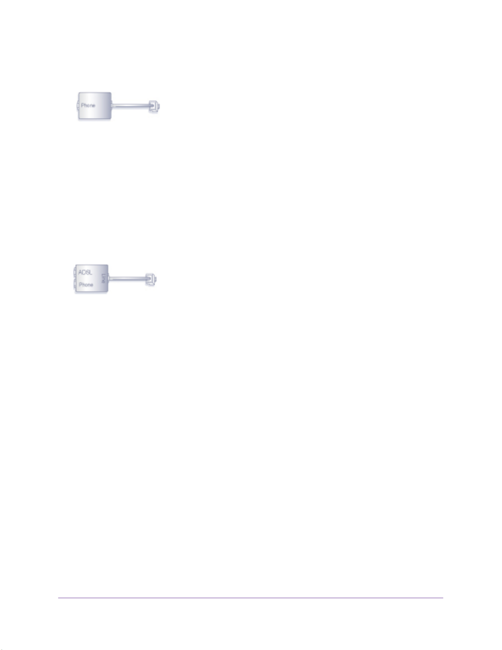
One-Line ADSL Microfilter
Plug the ADSL microfilter into the wall outlet and plug your phone equipment into the jack
labeled Phone. The modem router plugs directly into a separate DSL line. Plugging the
modem router into the phone jack blocks the Internet connection. If you do not have a
Hardware Setup
13
N300 Wireless ADSL2+ Modem Router DGN2200v4
separate DSL line for the modem router, the best thing to do is to use an ADSL microfilter
with a built-in splitter (see Two-Line ADSL Microfilter on page 13)
Plugs into DSL line
.
Figure 5. One-line ADSL microfilter
If you do not have a separate DSL line for the modem router, the second-best solution is to
get a separate splitter. To use a one-line filter with a separate splitter, insert the splitter into
the phone outlet, connect the one-line filter to the splitter, and connect the phone to the filter.
Two-Line ADSL Microfilter
Use an ADSL microfilter with a built-in splitter if you have a single wall outlet that provides
connectivity for both the modem router and your telephone equipment. Plug the ADSL
microfilter into the wall outlet, plug your phone equipment into the jack labeled Phone, and
plug the modem router into the jack labeled ADSL.
Plugs into the DSL line
Figure 6. Two-line ADSL microfilter with built-in splitter
Summary
•One-line ADSL microfilter. Use with a phone or fax machine.
•Splitter. Use with a one-line ADSL microfilter to share an outlet with a phone and the
modem router.
•Two-line ADSL microfilter with built-in splitter. Use to share an outlet with a phone
and the modem router.

Hardware Setup
14
N300 Wireless ADSL2+ Modem Router DGN2200v4
Cable Your Modem Router
You can use either a DSL or a cable/fiber Internet connection.
ADSL
Phone
Line
DSL Internet
Cable/fiber
or
Figure 7. Cable connections
CAUTION:
Incorrectly connecting a filter to your modem router blocks your DSL
connection.
For help with installation, see the installation guide that came in the package with your
product.
For information about how to access the modem router to view or change the settings, see
Chapter 2, Access the Modem Router.

15
2
2. Access the Modem Router
This chapter explains how to use NETGEAR genie to set up your modem router after you
complete cabling as described in the installation guide and in the previous chapter.
This chapter contains the following sections:
•Modem Router Setup Preparation
•Types of Logins and Access
•NETGEAR genie Setup
•Use NETGEAR genie after Installation
•Upgrade the Firmware
•Dashboard (Basic Home Screen)
•Join Your Wireless Network
•NETGEAR genie App and Mobile genie App

Access the Modem Router
16
N300 Wireless ADSL2+ Modem Router DGN2200v4
Modem Router Setup Preparation
You can set up your modem router with the NETGEAR genie automatically, or you can use
the genie menus and screens to set up your modem router manually. Before you start the
setup process, get your ISP information and make sure the computers and devices in the
network have the settings described here.
Use Standard TCP/IP Properties for DHCP
If you set up your computer to use a static IP address, you need to change the settings so
that it uses Dynamic Host Configuration Protocol (DHCP).
Gather ISP Information
If you have DSL broadband service, you might need the following information to set up your
modem router and to check that your Internet configuration is correct. Your Internet service
provider (ISP) should have provided you with all of the information needed to connect to the
Internet. If you cannot locate this information, ask your ISP to provide it. When your Internet
connection is working, you no longer need to launch the ISP’s login program on your
computer to access the Internet. When you start an Internet application, your modem router
automatically logs you in. Make sure that you have the following information:
•The ISP configuration information for your DSL account
•ISP login name and password
•Fixed or static IP address settings (special deployment by ISP; this is rare)
Wireless Devices and Security Settings
Make sure that the wireless device or computer that you are using supports WPA or WPA2
wireless security, which is the wireless security supported by the modem router.
Types of Logins and Access
There are separate types of logins that have different purposes. It is important that you
understand the difference so that you know which login to use when.
•Modem Router login logs you in to the modem router interface. For more information
about this login, see Use NETGEAR genie after Installation on page 18.
•ISP login logs you in to your Internet service. Your service provider has provided you with
this login information in a letter or some other way. If you cannot find this login
information, contact your service provider.
•Wireless network key or password. Your modem router is preset with a unique wireless
network name (SSID) and password for wireless access. This information is on the label
on the bottom of your modem router.

Access the Modem Router
17
N300 Wireless ADSL2+ Modem Router DGN2200v4
NETGEAR genie Setup
NETGEAR genie runs on any device with a web browser. Installation and basic setup takes
about 15 minutes to complete.
To use NETGEAR genie to set up your modem router:
1. Turn on the modem router by pressing the On/Off button.
2. Make sure that your computer or wireless device is connected to the modem router with an
Ethernet cable (wired) or wirelessly with the preset security settings listed on the bottom
label.
3. Launch your Internet browser.
•The first time you set up the Internet connection for your modem router, the browser
goes to http://www.routerlogin.net, and the NETGEAR genie screen displays.
•If you already used the NETGEAR genie, type in the http://www.routerlogin.net
address field for your browser to display the NETGEAR genie screen. See Use
NETGEAR genie after Installation on page 18.
4. Follow the onscreen instructions to complete NETGEAR genie setup.
NETGEAR genie guides you through connecting the modem router to the Internet.
If the browser cannot display the web page:
•Make sure that the computer is connected to one of the four LAN Ethernet ports or
wirelessly to the modem router.
•Make sure that the modem router has full power, and that its WiFi LED is lit.
•To make sure that the browser does not cache the previous page, close and reopen the
browser.
•Browse to http://www.routerlogin.net.
•If the computer is set to a static or fixed IP address (this is uncommon), change it to
obtain an IP address automatically from the modem router.

Access the Modem Router
18
N300 Wireless ADSL2+ Modem Router DGN2200v4
If the modem router does not connect to the Internet:
1. Review your settings to be sure that you have selected the correct options and typed
everything correctly.
2. Contact your ISP to verify that you have the correct configuration information.
3. Read Chapter 10, Troubleshooting. If problems persist, register your NETGEAR product and
contact NETGEAR technical support.
Use NETGEAR genie after Installation
When you first set up your modem router, NETGEAR genie automatically starts when you
launch an Internet browser on a computer that is connected to the modem router. If you want
to view or change settings for the modem router, you can use genie again.
1. Launch your browser from a computer or wireless device that is connected to the
modem router.
2. Type http://www.routerlogin.net http://www.routerlogin.comor .
The login window displays.
3. Enter admin for the modem router user name and password for the modem router
password, both in lowercase letters.
Note: The modem router user name and password are different from the user
name and password for logging in to your Internet connection. For
more information, see Types of Logins and Access on page 16.
Upgrade the Firmware
When you set up your modem router and are connected to the Internet, the modem router
automatically checks for you to see if newer firmware is available. If it is, a message is
displayed on the top of the screen. For more information, see Update the Modem Router
Firmware on page 73.
Click the message when it shows up, and click Yes to upgrade the modem router with the
latest firmware. After the upgrade, the modem router restarts.
CAUTION:
Do not try to go online, turn off the modem router, shut down the computer,
or do anything else to the modem router until the modem router finishes
restarting and the Power LED has stopped blinking for several seconds.

Access the Modem Router
19
N300 Wireless ADSL2+ Modem Router DGN2200v4
Dashboard (Basic Home Screen)
The modem router Basic Home screen has a dashboard that lets you see the status of your
Internet connection and network at a glance. You can click any of the six sections of the
dashboard to view and change the settings. The left column has menus. You can use the
Advanced tab to access more menus and screens.
Menus
(Click the
Advanced
tab to view
more)
Language
Help
Dashboard
(Click to
view details)
Figure 8. Basic Home screen with dashboard, language, and online help
•Home. This dashboard screen displays when you log in to the . modem router
•Internet. Set, update, and check the ISP settings of your modem router.
•Wireless. View or change the wireless settings for your modem router.
•Attached Devices. View the devices connected to your network.
•Parental Controls. Download and set up parental controls to prevent objectionable
content from reaching your computers.
•ReadySHARE. If you connected a USB storage device to the modem router, then it is
displayed here.
•Guest Network. Set up a guest network to allow visitors to use your modem router’ s
Internet connection.
•Advanced tab. Set the modem router up for unique situations such as when remote
access by IP or by domain name from the Internet is needed. See Chapter 8, Advanced
Settings. You need a solid understanding of networking to use this tab.
•Help & Support. Go to the NETGEAR support site to get information, help, and product
documentation. These links work once you have an Internet connection.

Access the Modem Router
20
N300 Wireless ADSL2+ Modem Router DGN2200v4
Join Your Wireless Network
You can use the manual or the WPS method to join your wireless network. For instructions
about how to set up a guest network, see on page 31.Set Up a Guest Network
Manual Method
With the manual method, choose the network that you want and type its password to
connect.
To connect manually:
1. On your computer or wireless device, open the software that manages your wireless
connections. This software scans for all wireless networks in your area.
2. Look for your network and select it.
The unique WiFi network name (SSID) and password are on the modem router label. If
you changed these settings, look for the network name that you used.
3. Enter the modem router password and click Connect.
Wi-Fi Protected Setup (WPS) Method
Wi-Fi Protected Setup (WPS) lets you connect to a secure WiFi network without typing its
password. Instead, press a button or enter a PIN. NETGEAR calls WPS Push 'N' Connect.
Some older WiFi equipment is not compatible with WPS. WPS works only with WPA2 or WPA
wireless security.
To use WPS to join the wireless network:
1. Press the WPS button on the modem router front panel .
2. Within 2 minutes, press the WPS button on your wireless device, or follow the WPS
instructions that came with the device.
The WPS process automatically sets up your wireless computer with the network
password and connects you to the wireless network.
Access the Modem Router
21
N300 Wireless ADSL2+ Modem Router DGN2200v4
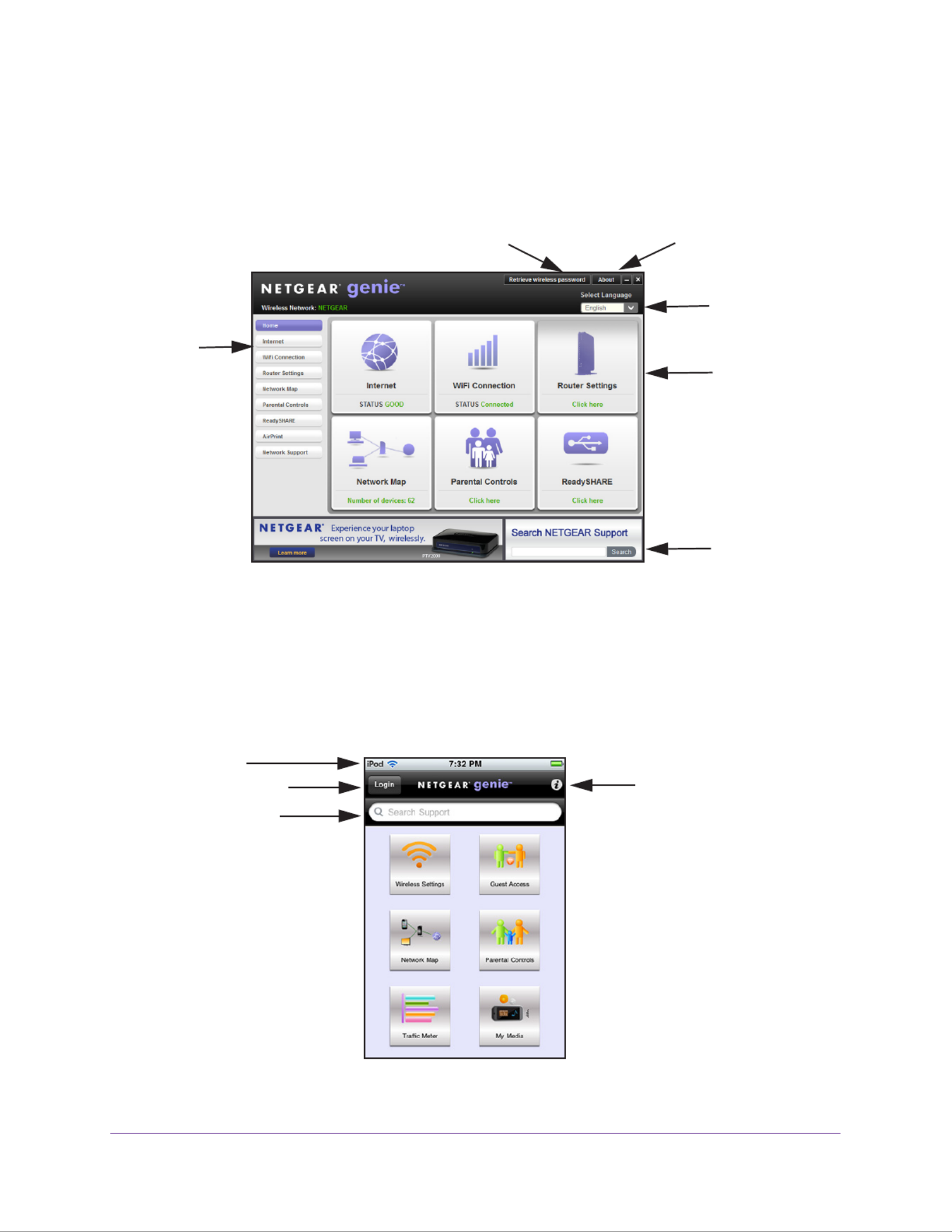
NETGEAR genie App and Mobile genie App
The genie app is the easy dashboard for managing, monitoring, and repairing your home
network. See the NETGEAR genie App User Manual for details about the genie apps.
Menu
Language
Support
Dashboard
(Click to
view
details)
Retrieve wireless password About genie
Figure 9. genie app dashboard
The genie app can help you with the following:
•Automatically repair common wireless network problems.
•Have easy access to features like Live Parental Controls, guest access, Internet traf fic
meter, speed test, and more.
The genie mobile app works on your iPhone, iPad, or Android phone:
Log in to the router Information about
genie mobile app
Phone status
Search NETGEAR
support and the connected
router
Figure 10. genie mobile app home screen

22
3
3. NETGEAR genie Basic Settings
This chapter contains the following sections:
•Internet Setup
•Parental Controls
•Basic Wireless Settings
•Set Up a Guest Network
•View Attached Devices
For information about ReadySHARE USB storage, see .Chapter 5, USB Storage

NETGEAR genie Basic Settings
23
N300 Wireless ADSL2+ Modem Router DGN2200v4
Internet Setup
The Internet Setup screen is where you view or change basic ISP information.
Note: You can use the Setup Wizard to detect the Internet connection and
automatically set up the modem router. See on Setup Wizard
page 34.
To view or change the basic Internet setup:
1. From the Home screen, select Internet.
Scroll to
view more
settings
The fields that display in the Internet Setup screen depend on whether your Internet
connection requires a login.
•Yes. Select the encapsulation method and enter the login name. If you want to
change the login time-out, enter a new value in minutes.
•No. Enter the account and domain names, only if needed.
2. Enter the settings for the IP address and DNS server.
The default settings usually work fine. If you have problems with your connection, check
the ISP settings.
3. Click Apply to save your settings.
4. Click Test to test your Internet connection.
If the NETGEAR website does not display within 1 minute, see Chapter 10,
Troubleshooting.

NETGEAR genie Basic Settings
24
N300 Wireless ADSL2+ Modem Router DGN2200v4
Internet Setup Screen Fields
The following descriptions explain all of the possible fields in the Internet Setup screen. The
fields that display in this screen depend on whether tan ISP login is required.
Does Your Internet connection require a login? Answer either yes or no.
These fields display when no login is required:
•Account Name (If required). Enter the account name provided by your ISP. This might
also be called the host name.
•Domain Name (If required). Enter the domain name provided by your ISP.
These fields display when your ISP requires a login:
•Internet Service Provider. The choices are PPPoE or PPPoA.
•Login. The login name provided by your ISP. This login name is often an email address.
•Password. The password that you use to log in to your ISP.
•Service Name (if Required). If your ISP provided a service name, enter it here.
•Connection Mode. Always On, Dial on Demand, or Manually Connect.
•Idle Timeout (In minutes). If you want to change the login time-out, enter a new value in
minutes. This setting determines how long the modem router keeps the Internet
connection active after there is no Internet activity from the LAN. A value of 0 (zero)
means never log out.
Internet IP Address.
•Get Dynamically from ISP. Your ISP uses DHCP to assign your IP address. Your ISP
automatically assigns these addresses.
•Use Static IP Address. Enter the IP address, IP subnet mask, and the gateway IP
address that your ISP assigned. The gateway is the ISP’s modem router to which your
modem router will connect.
Domain Name Server (DNS) Address. The DNS server is used to look up site addresses
based on their names.
•Get Automatically from ISP. Your ISP uses DHCP to assign your DNS servers. Your ISP
automatically assigns this address.
•Use These DNS Servers. If you know that your ISP requires specific servers, select this
option. Enter the IP address of your ISP’s primary DNS server. If a secondary DNS server
address is available, enter it also.
NAT (Network Address Translation). NAT allows computers on your home network to
share the modem router Internet connection. NAT is enabled by default because it is needed
in most situations. The following settings are available:
•Enable
•Disable
•Disable Port Scan and DoS Protection

NETGEAR genie Basic Settings
25
N300 Wireless ADSL2+ Modem Router DGN2200v4
Router MAC Address. The Ethernet MAC address that the modem router uses on the
Internet port. Some ISPs register the MAC address of the network interface card in your
computer when your account is first opened. They accept traffic only from the MAC address
of that computer. This feature allows your modem router to use your computer’s MAC
address (also called cloning).
•Use Default Address. Use the default MAC address.
•Use Computer MAC Address. The modem router captures and uses the MAC address of
the computer that you are now using. You have to use the one computer that the ISP
allows.
•Use This MAC Address. Enter the MAC address that you want to use.
Parental Controls
The first time you select Parental Controls from the Basic Home screen, your browser goes
to the Live Parental Controls website. You can learn more about Live Parental Controls or
download the application.
Figure 11. Live Parental Controls website
To set up Live Parental Controls:
1. Select Parental Controls on the Dashboard screen.
2. Click either the Windows Users or button. Mac Users
3. Follow the onscreen instructions to download and install the NETGEAR Live Parental
Controls Management Utility.

NETGEAR genie Basic Settings
26
N300 Wireless ADSL2+ Modem Router DGN2200v4
After installation, Live Parental Controls automatically starts.
4. Click Next, read the note, and click Next again to proceed.
Because Live Parental Controls uses free OpenDNS accounts, you are prompted to log in
or create a free account.
5. Select the radio button that applies to you and click Next.
•If you already have an OpenDNS account, leave the Ye s radio button selected.
•If you do not have an OpenDNS account, select the radio button. No
If you are creating an account, the following screen displays:
•Fill in the fields and click .Next

NETGEAR genie Basic Settings
27
N300 Wireless ADSL2+ Modem Router DGN2200v4
After you log on or create your account, the filtering level screen displays:
6. Select the radio button for the filtering level that you want and click Next.
7. Click the Take me to the status screen button.
Parental controls are now set up for the modem router. The dashboard shows Parental
Controls as Enabled.
Basic Wireless Settings
The Wireless Settings screen lets you view or configure the wireless network setup.
The modem router comes with preset security. This means that the Wi-Fi network name
(SSID), network key (password), and security option (encryption protocol) are preset in the
factory. You can find the preset SSID and password on the bottom of the unit.
Note: The preset SSID and password are uniquely generated for every
device to protect and maximize your wireless security.

NETGEAR genie Basic Settings
28
N300 Wireless ADSL2+ Modem Router DGN2200v4
NETGEAR recommends that you do not change your preset security settings. If you change
your preset security settings, make a note of the new settings and store it in a safe place
where you can easily find it.
If you use a wireless computer to change the wireless network name (SSID) or other wireless
security settings, you are disconnected when you click Apply. To avoid this problem, use a
computer with a wired connection to access the modem router.
To view or change basic wireless settings:
1. Select Basic > Wireless.
The screen sections, settings, and procedures are explained in the following sections.
2. Make any changes that are needed.
3. Click Appl.
Your settings are saved.
If you were connected wirelessly to the modem router and you changed the SSID or
wireless security, you are disconnected from the network.
4. Set up and test your wireless devices and computers to make sure that they can connect
wirelessly. If they do not, check the following:
•Is your wireless device or computer connected to your network or another wireless
network in your area? Some wireless devices automatically connect to the first open
network (without wireless security) that they discover.
•Does your wireless device or computer show up on the Attached Devices screen? If it
does, it is connected to the network.
•If you are not sure what the network name (SSID) or password is, look on the label on
the bottom of your modem router.

NETGEAR genie Basic Settings
29
N300 Wireless ADSL2+ Modem Router DGN2200v4
Wireless Settings Screen Fields
You can use this screen to view or change the wireless network settings and the security
option.
Wireless Network
Enable SSID Broadcast. This setting allows the modem router to broadcast its SSID so
wireless stations can see this wireless name (SSID) in their scanned network lists. This
check box is selected by default. To turn off the SSID broadcast, clear this check box, and
click Apply.
Enable Wireless Isolation. If this check box is selected, computers or wireless devices that
join the network can use the Internet, but cannot access each other or access Ethernet
devices on the network.
Name (SSID). The SSID is also known as the wireless network name. Enter a 32-character
(maximum) name in this field. This field is case-sensitive. The default SSID is randomly
generated, and NETGEAR strongly recommends that you do not change this setting.
Region. The location where the modem router is used. Select from the countries in the list. In
the United States, the region is fixed to United States and is not changeable.
Channel. This setting is the wireless channel the gateway uses. Enter a value from 1 through
13. (For products in the North America market, only Channels 1 through 11 can be operated.)
Do not change the channel unless you experience interference (shown by lost connections or
slow data transfers). If this happens, experiment with different channels to see which is the
best.
When you use multiple access points, it is better if adjacent access points use different radio
frequency channels to reduce interference. The recommended channel spacing between
adjacent access points is 5 channels (for example, use Channels 1 and 6, or 6 and 11).
Mode. Up to 145 Mbps is the default setting, which allows 802.11n and 802.11g wireless
devices to join the network. The other settings are Up to 54 Mbps, and Up to 300 Mbps.
Security Options Settings
The Security Options section of the Wireless Settings screen lets you change the security
option and passphrase. NETGEAR recommends that you do not change these settings,
but this section explains how. Do not disable security.
Wireless Security Options
A security option is the type of security protocol applied to your wireless network. The
security protocol in force encrypts data transmissions and ensures that only trusted devices
receive authorization to connect to your network. Wi-Fi Protected Access (WPA) has several
options including pre-shared key (PSK) encryption.
This section presents an overview of the security options and provides guidance on when to
use which option. It is also possible to set up a guest network without wireless security.
NETGEAR does recommend this.not

NETGEAR genie Basic Settings
30
N300 Wireless ADSL2+ Modem Router DGN2200v4
WPA encryption is built into all hardware that has the Wi-Fi-certified seal. This seal means
that the product is authorized by the Wi-Fi Alliance (http://www.wi-fi.org/) because it complies
with the worldwide single standard for high-speed wireless local area networking.
WPA uses a passphrase for authentication and to generate the initial data encryption keys.
Then it dynamically varies the encryption key. WPA-PSK uses Temporal Key Integrity
Protocol (TKIP) data encryption, implements most of the IEEE 802.11i standard, and works
with all wireless network interface cards, but not all wireless access points.
WPA2-PSK is stronger than WPA-PSK. It is advertised to be theoretically indecipherable due
to the greater degree of randomness in encryption keys that it generates. WPA2-PSK gets
higher speed because it is implemented through hardware, while WPA-PSK is usually
implemented through software. WPA2-PSK uses a passphrase to authenticate and generate
the initial data encryption keys. Then it dynamically varies the encryption key.
WPS-PSK + WPA2-PSK Mixed Mode can provide broader support for all wireless clients.
WPA2-PSK clients get higher speed and security, and WPA-PSK clients get decent speed
and security. For help with WPA settings on your wireless computer or device, see the
instructions that came with your product.
Change WPA Security Option and Passphrase
You can change the security settings for your modem router. If you do so, then write down the
new settings and store them in a secure place for future reference.
To change the WPA settings:
1. Select Basic > Wireless Settings.
2. Under Security Options, select the WPA option you want.
3. In the Passphrase field that displays when you select a WPA security option, enter the
network key (password) that you want to use. It is a text string from 8 to 63 characters.

NETGEAR genie Basic Settings
31
N300 Wireless ADSL2+ Modem Router DGN2200v4
Set Up a Guest Network
Adding a guest network allows visitors at your home to use the Internet without giving them
your wireless security key.
To set up a guest network:
1. Select .Basic > Guest Network
2. Select any of the following wireless settings:
Enable Guest Network. When this check box is selected, the guest network is enabled,
and guests can connect to your network using the SSID of this profile.
Enable SSID Broadcast. If this check box is selected, the wireless access point
broadcasts its name (SSID) to all wireless stations. Stations with no SSID can adopt the
correct SSID for connections to this access point.
Allow guest to access My Local Network. If this check box is selected, anyone who
connects to this SSID has access to your local network, not just Internet access.
Enable Wireless Isolation. If this check box is selected, wireless computers or devices
that join the network can use the Internet but cannot access each other or access
Ethernet devices on the network.
3. Give the guest network a name.
The guest network name is case-sensitive and can be up to 32 characters. You then
manually configure the wireless devices in your network to use the guest network name
in addition to the main SSID.
4. Select a security option from the list.
The security options are described in on page 29.Wireless Security Options
5. Click Apply.
Your settings are saved.

NETGEAR genie Basic Settings
32
N300 Wireless ADSL2+ Modem Router DGN2200v4
View Attached Devices
Use the Attached Device screen to view all computers or devices that are currently
connected to your network.
To go to the Attached Devices screen:
From the Basic Home screen, select .Attached Devices
Wired devices are connected to the modem router with Ethernet cables. Wireless devices
have joined the wireless network.
•# (number). The order in which the device joined the network.
•IP Address. The IP address that the modem router assigned to this device when it joined
the network. This number can change if a device is disconnected and rejoins the network.
•Device Name. If the device name is known, it is shown here.
•MAC Address. The unique MAC address for each device does not change. The MAC
address is typically shown on the product label.
Click to update this screen.Refresh

33
4
4. NETGEAR genie Advanced Home
This chapter contains the following sections:
•NETGEAR genie Advanced Home Screen
•Setup Wizard
•WPS Wizard
•WAN Setup
•LAN Setup
•Quality of Service (QoS) Setup
Some selections on the Advanced Home screen are described in separate chapters:
•USB Storage. See Chapter 5, USB Storage.
•Security. See .Chapter 6, Security
•Administration. See Chapter 7, Administration.
•Advanced Setup. See Chapter 8, Advanced Settings.
•Advanced VPN. See Chapter 9, Virtual Private Networking.
NETGEAR genie Advanced Home
34
N300 Wireless ADSL2+ Modem Router DGN2200v4
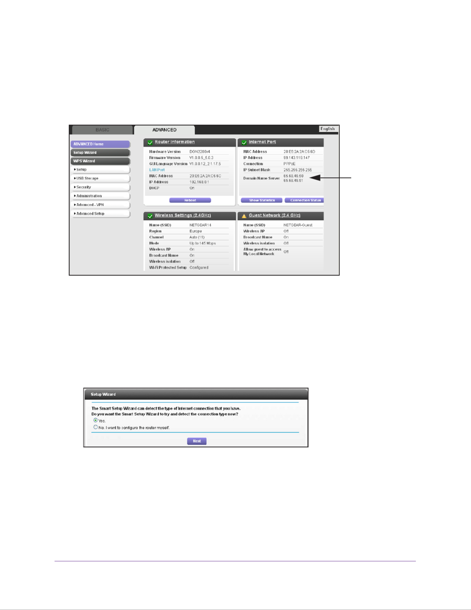
NETGEAR genie Advanced Home Screen
The genie Advanced Home dashboard presents status information. The content is the same
as what is on the Router Status screen available from the Administration menu. The genie
Advanced Home screen is shown in the following figure:
This screen is
also displayed
through the
Administration
menu.
Setup Wizard
You can use the Setup Wizard to detect your Internet settings and automatically set up your
modem router. The Setup Wizard is not the same as the genie screens that display the first
time you connect to your modem router to set it up.
To use the Setup Wizard:
1. Select Advanced > Setup Wizard.
2. Select either Yes or No, I want to configure the router myself.
If you select No, you are taken to the Internet Setup screen (see on Internet Setup
page 23).
3. Select Yes and select your location.
4. Click Next.

NETGEAR genie Advanced Home
35
N300 Wireless ADSL2+ Modem Router DGN2200v4
The Setup Wizard searches your Internet connection for servers and protocols to
determine your ISP configuration. The following screen displays:
WPS Wizard
The WPS Wizard helps you add a WPS-capable client device (a wireless device or
computer) to your network. On the client device, either press its WPS button or locate its
WPS PIN.
To use the WPS Wizard:
1. Select Advanced > WPS Wizard.
2. Click . Next
The following screen lets you select the method for adding the WPS client (a wireless
device or computer).
You can use either the push button or PIN method.
3. Select either Push Button or PIN Number.
•To use the push button method, either click the button on this screen, or press WPS
the WPS button on the side of the modem router. Within 2 minutes, go to the wireless
client and press its button to join the network without entering a password.WPS

NETGEAR genie Advanced Home
36
N300 Wireless ADSL2+ Modem Router DGN2200v4
•To use the PIN method, select the PIN Number radio button, enter the client security
PIN, and click .Next
Within 2 minutes, go to the client device and use its WPS software to join the network
without entering a password.
The modem router attempts to add the WPS-capable device. The WPS LED on the
front of the modem router blinks green. When the modem router establishes a WPS
connection, the LED is solid green, and the modem router WPS screen displays a
confirmation message.
WAN Setup
You can use the WAN Setup screen to specify the ADSL or Ethernet port setting for your
Internet connection, though by default the modem router automatically detects the Internet
port. The WAN Setup screen also lets you configure a DMZ (demilitarized zone) server,
change the maximum transmit unit (MTU) size, and enable the modem router to respond to a
ping on the WAN (Internet) port.
To view or change the WAN settings:
1. Select Advanced > Setup > WAN Setup.
2. Specify the settings for your Internet connection.
The fields in this screen are described in the following section.

NETGEAR genie Advanced Home
37
N300 Wireless ADSL2+ Modem Router DGN2200v4
3. Click Apply.
WAN Setup Screen Fields
The following fields are available:
•WAN Preference. By default this field is set to Auto-Detect so that the modem router
automatically detects if the Internet connection is through the ADSL port or the
WAN/Ethernet port 4. You can use this field to select Must use DSL WAN or Must use
Ethernet WAN.
•Use port 4 as. By default, Auto-Detect is selected so that the modem router detects if
Ethernet port 4 is used as a LAN or WAN port. For example, if you connect a computer to
Ethernet port 4, then it works as a LAN port. You can select LAN or WAN if you do not
want to use the auto-detect setting.
•Disable Port Scan and DoS Protection. DoS protection protects your LAN against
denial of service attacks such as Syn flood, Smurf Attack, Ping of Death, Teardrop Attack,
UDP Flood, ARP Attack, Spoofing ICMP, Null Scan, and many others. This should be
disabled only in special circumstances.
•Default DMZ Server. This feature is sometimes helpful when you are playing online
games or videoconferencing. Be careful when using this feature because it makes the
firewall security less effective. See the following section, Default DMZ Server.
•Respond to Ping on Internet Port. If you want the modem router to respond to a ping
from the Internet, select this check box. Use this feature only as a diagnostic tool
because it allows your modem router to be discovered. Do not select this check box
unless you have a specific reason.
•Disable IGMP Proxying. The IGPM proxying feature lets a LAN computer receive the
multicast traffic directed to it from the Internet. Selecting this check box prevents this from
occurring.
•MTU Size (in bytes). The normal MTU (maximum transmit unit) value for most Ethernet
networks is 1500 bytes, or 1492 bytes for PPPoE connections. For some ISPs, you might
need to reduce the MTU. This is rarely required. You should change the setting in this
field only if you are sure that it is necessary for your ISP connection. See Change the
MTU Size on page 38.
•NAT Filtering. Network Address Translation (NAT) determines how the modem router
processes inbound traffic. Secured NAT provides a secured firewall to protect the
computers on the LAN from attacks from the Internet, but might prevent some Internet
games, point-to-point applications, or multimedia applications from functioning. Open
NAT provides a much less secured firewall, but allows almost all Internet applications to
function.
•Disable SIP ALG. The Session Initiation Protocol (SIP) Application Level Gateway (ALG)
is enabled by default to optimize VoIP phone calls that use the SIP. Select the Disable
SIP ALG check box to disable the SIP ALG. Disabling the SIP ALG might be useful when
you are running certain applications.

NETGEAR genie Advanced Home
38
N300 Wireless ADSL2+ Modem Router DGN2200v4
Default DMZ Server
The default DMZ server feature is helpful when you are using some online games and
videoconferencing applications that are incompatible with Network Address Translation
(NAT). The modem router recognizes some of these applications and works correctly with
them, but other applications might not function well. In some cases, one local computer can
run the application correctly if that computer’s IP address is entered as the default DMZ
server.
WARNING:
DMZ servers pose a security risk. A computer designated as the
default DMZ server loses much of the protection of the firewall and
is exposed to exploits from the Internet. If compromised, the DMZ
server computer can be used to attack other computers on your
network.
The modem router discards traffic from the Internet that is not a response to one of your
computers or a service that you have set up in the Port Forwarding/Port Triggering screen.
Instead of discarding this traffic, you can have the modem router forward the traffic to one
computer on your network. This computer is called the default DMZ server.
To set up a default DMZ server:
1. Select Advanced > Setup > WAN Setup. screen.
2. Select the Default DMZ Server check box.
3. Type the IP address.
4. Click Apply.
Your changes are saved.
Change the MTU Size
The maximum transmission unit (MTU) is the largest data packet a network device transmits.
When one network device communicates across the Internet with another, the data packets
travel through many devices along the way. If a device in the data path has a lower MTU
setting than the other devices, the data packets are split or “fragmented” to accommodate the
device with the smallest MTU.
The best MTU setting for NETGEAR equipment is often just the default value. In some
situations, changing the value fixes one problem but causes another. Leave the MTU
unchanged unless one of these situations occurs:
•You have problems connecting to your ISP or other Internet service, and the technical
support of either the ISP or NETGEAR recommends changing the MTU setting. These
web-based applications might require an MTU change:
-A secure website that does not open, or displays only part of a web page

NETGEAR genie Advanced Home
39
N300 Wireless ADSL2+ Modem Router DGN2200v4
-Yahoo email
-MSN portal
-America Online’s DSL service
•You use VPN and have severe performance problems.
•You used a program to optimize MTU for performance reasons, and now you have
connectivity or performance problems.
Note: An incorrect MTU setting can cause Internet communication
problems. For example, you might not be able to access certain
websites, frames within websites, secure login pages, or FTP or POP
servers.
If you suspect an MTU problem, a common solution is to change the MTU to 1400. If you are
willing to experiment, you can gradually reduce the MTU from the maximum value of 1500
until the problem goes away. The following table describes common MTU sizes and
applications.
Table 2. Common MTU sizes
MTU Application
1500 The largest Ethernet packet size. This setting is typical for connections that do not use
PPPoE or VPN, and is the default value for NETGEAR modem routers, adapters, and
switches.
1492 Used in PPPoE environments.
1472 Maximum size to use for pinging. (Larger packets are fragmented.)
1468 Used in some DHCP environments.
1460 Usable by AOL if you do not have large email attachments, for example.
1436 Used in PPTP environments or with VPN.
1400 Maximum size for AOL DSL.
576 Typical value to connect to dial-up ISPs.
To change the MTU size:
1. Select Advanced > Setup > WAN Setup.
2. In the MTU Size field, enter a value from 64 to 1500.
3. Click Apply.
Your change is saved.

NETGEAR genie Advanced Home
40
N300 Wireless ADSL2+ Modem Router DGN2200v4
LAN Setup
The LAN Setup screen allows configuration of LAN IP services such as Dynamic Host
Configuration Protocol (DHCP) and Routing Information Protocol (RIP). The modem router is
shipped preconfigured to use private IP addresses on the LAN side and to act as a DHCP
server. The modem router’s default LAN IP configuration is:
•LAN IP address. 192.168.0.1
•Subnet mask. 255.255.255.0
These addresses are part of the designated private address range for use in private networks
and are suitable for most applications.
By default, the modem router acts as a DHCP server. The modem router assigns IP, DNS
server, and default gateway addresses to all computers connected to the LAN. The assigned
default gateway address is the LAN address of the modem router. The modem router tests
each address before it is assigned to avoid duplicate addresses on the LAN. For most
applications, the default DHCP and TCP/IP settings of the modem router are satisfactory.
The modem router delivers the following parameters to any LAN device that requests DHCP:
•IP address
•Subnet mask
•Gateway IP address (the modem router’s LAN IP address)
•Primary DNS server (if specified in the Internet Setup screen), otherwise, the modem
router’s LAN IP address)
•Secondary DNS server if you entered this in the Internet Setup screen
If you change the LAN IP address of the modem router while connected through the browser,
you are disconnected from the network.
To change the LAN settings:
1. Select .Advanced > Setup > LAN Setup

NETGEAR genie Advanced Home
41
N300 Wireless ADSL2+ Modem Router DGN2200v4
2. Specify the settings that you want to customize (see LAN Setup Screen Settings).
3. Click Apply.
Your changes are saved.
LAN Setup Screen Settings
The following settings are available.
Device Name. By default, this is DGN2200v4 (the modem router model). You can change
it to another name if you prefer.
LAN TCP/IP Setup
•IP Address. The LAN IP address of the modem router.
•IP Subnet Mask. The LAN subnet mask of the modem router. Combined with the IP
address, the IP subnet mask allows a device to know which other addresses are local to
it, and which addresses have to be reached through a gateway or modem router.
•RIP Direction. Router Information Protocol (RIP) allows the modem router to exchange
routing information with other routers. This setting controls how the modem router sends
and receives RIP packets. Both is the default setting. With the Both or Out Only setting,
the modem router broadcasts its routing table periodically. With the Both or In Only
setting, the modem router incorporates the RIP information that it receives.
•RIP Version. This setting controls the format and the broadcasting method of the RIP
packets that the modem router sends. It recognizes both formats when receiving. By
default, the RIP function is disabled.
-RIP-1 is universally supported. It is adequate for most networks, unless you have an
unusual network setup.
-RIP-2 carries more information. Both RIP-2B and RIP-2M send the routing data in
RIP-2 format. RIP-2B uses subnet broadcasting. RIP-2M uses multicasting.
Use Router as a DHCP Server
Usually, this check box is selected so that the modem router functions as a Dynamic Host
Configuration Protocol (DHCP) server.
•Starting IP Address. Specify the start of the range for the pool of IP addresses in the
same subnet as the modem router.
•Ending IP Address. Specify the end of the range for the pool of IP addresses in the
same subnet as the modem router.
Address Reservation
When you specify a reserved IP address for a computer on the LAN, that computer receives
the same IP address each time it accesses the modem router’s DHCP server. Assign
reserved IP addresses to servers that require permanent IP settings. See Address
Reservation on page 42.

NETGEAR genie Advanced Home
42
N300 Wireless ADSL2+ Modem Router DGN2200v4
Specify DHCP Server Settings
By default, the modem router is set up as a DHCP server. You can specify the range of
addresses that the modem router assigns. You can also use another device on your network
as the DHCP server, or specify the network settings of all of your computers.
To specify the pool of IP addresses that the modem router assigns:
1. Select .Advanced > LAN Setup
2. Make sure that the Use Router as a DHCP Server check box is selected.
3. Specify the range of IP addresses.
For example, using the default addressing scheme, define a range between 192.168.0.2
and 192.168.0.254, although you might want to save part of the range for devices with
fixed addresses.
•In the Starting IP Address field, specify the start of the range for the pool of IP
addresses in the same subnet as the modem router.
•In the Ending IP Address field, specify the end of the range for the pool of IP
addresses in the same subnet as the modem router.
4. Click Apply.
Your changes are saved.
To disable the DHCP Server feature in the modem router:
1. Select .Advanced > LAN Setup
2. Clear the Use Router as DHCP Server check box
3. Click Apply.
4. If no DHCP server is on your network, set your computers’ IP addresses manually so that
they can access the modem router.
Address Reservation
When you specify a reserved IP address for a computer on the LAN, that computer always
receives the same IP address each time it accesses the modem router’s DHCP server.
Reserved IP addresses should be assigned to computers or servers that require permanent
IP settings.
To reserve an IP address:
1. Select .Advanced > Setup > LAN Setup
2. In the Address Reservation section of the screen, click the Add button.
3. In the IP Address field, type the IP address to assign to the computer or server.
Choose an IP address from the modem router’s LAN subnet, such as 192.168.0.x.
4. Type the MAC address of the computer or server.

NETGEAR genie Advanced Home
43
N300 Wireless ADSL2+ Modem Router DGN2200v4
Tip: If the computer is already on your network, you can copy its MAC
address from the Attached Devices screen and paste it here.
5. Click Apply.
The reserved address is entered into the table.
The reserved address is not assigned until the next time the computer contacts the
modem router’s DHCP server. Reboot the computer, or access its IP configuration and
force a DHCP release and renew.
To edit or delete a reserved address entry, select the radio button next to the reserved
address you want to edit or delete. Then c .lick or Edit Delete
Quality of Service (QoS) Setup
QoS is an advanced feature that can be used to prioritize some types of traffic ahead of
others. The modem router can provide QoS prioritization over the wireless link and on the
Internet connection.
WMM QoS for Wireless Multimedia Applications
The modem router supports Wi-Fi Multimedia Quality of Service (WMM QoS) to prioritize
wireless voice and video traffic over the wireless link. WMM QoS provides prioritization of
wireless data packets from different applications based on four access categories: voice,
video, best effort, and background. For an application to receive the benefits of WMM QoS,
both it and the client running that application have to have WMM enabled. Legacy
applications that do not support WMM and applications that do not require QoS, are assigned
to the best effort category, which receives a lower priority than voice and video. WMM QoS is
enabled by default.
To disable WMM QoS:
1. Select . Advanced > Setup > QoS Setup
2. Clear the Enable WMM check box
3. Click Apply.

NETGEAR genie Advanced Home
44
N300 Wireless ADSL2+ Modem Router DGN2200v4
Set Up QoS for Internet Access
You can give prioritized Internet access to the following types of traffic:
•Specific applications
•Specific online games
•Individual Ethernet LAN ports of the modem router
•A specific device by MAC address
To specify prioritization of traffic, create a policy for the type of traffic and add the policy to the
QoS Policy table in the QoS Setup screen. For convenience, the QoS Policy table lists many
common applications and online games that can benefit from QoS handling.
QoS for Applications and Online Gaming
To create a QoS policy for applications and online games:
1. Select Advanced > Setup > QoS Setup.
2. Select the Turn Internet Access QoS On check box.
3. Click the Setup QoS Rule button.
The QoS Priority Rule list displays.
You can edit or delete a rule by selecting its radio button and clicking either the or Edit
Delete button. You can also delete all the rules by clicking the button.Delete All

NETGEAR genie Advanced Home
45
N300 Wireless ADSL2+ Modem Router DGN2200v4
4. To add a priority rule, scroll down to the bottom of the QoS Setup screen and click Add
Priority Rule.
5. In the QoS Policy for field, type the name of the application or game.
6. In the Priority Category list, select either Applications or Online Gaming.
A list of applications or games displays.
7. Select an existing item from the list, scroll and select Add a New Application, or Add a
New Game, as applicable.
8. If prompted, in the Connection Type list, select either TCP, UDP, or both (TCP/UDP). Specify
the port number or range of port numbers that the application or game uses.
9. From the Priority list, select the priority for Internet access for this traffic relative to other
applications and traffic. The options are Low, Normal, High, and Highest.
10. Click Apply
The rule is saved in the QoS Policy list.
The QoS Setup screen displays.
QoS for a Modem Router LAN Port
To create a QoS policy for a device connected to a LAN port:
1. Select . Advanced > Setup > QoS Setup
2. Select the Turn Internet Access QoS On check box.
3. Click the Setup QoS Rule button.
4. Click the Add Priority Rule button.
5. From the Priority Category list, select Ethernet LAN Port.

NETGEAR genie Advanced Home
46
N300 Wireless ADSL2+ Modem Router DGN2200v4
6. From the QoS Policy for list, select the LAN port.
7. From the Priority list, select the priority for Internet access for this port’s traffic relative to
other applications. The options are Low, Normal, High, and Highest.
8. Click Apply
The rule is saved in the QoS Policy list.
The QoS Setup screen displays.
9. In the QoS Setup screen, click Apply.
QoS for a MAC Address
To create a QoS policy for traffic from a specific MAC address:
1. Select Advanced > Setup > QoS Setup, and click the Setup QoS Rule button.
The QoS Setup screen displays.
2. Click . Add Priority Rule
3. From the Priority Category list, select MAC Address.
4. If the device to be prioritized appears in the MAC Device List, select its radio button.
The information from the MAC Device List populates the policy name, MAC Address, and
Device Name fields. If the device does not appear in the MAC Device List, click Refresh.
If it still does not appear, fill in these fields manually.
5. From the Priority list, select the priority for Internet access for this device’s traffic reelative to
other applications and traffic. The options are Low, Normal, High, and Highest.
6. Click Apply.
This rule is saved in the QoS Policy list.
The QoS Setup screen displays.
7. Select the Turn Internet Access QoS On check box.

NETGEAR genie Advanced Home
47
N300 Wireless ADSL2+ Modem Router DGN2200v4
8. Click Apply.
Edit or Delete an Existing QoS Policy
To edit or delete a QoS policy:
1. Select .Advanced > QoS Setup
2. Select the radio button next to the QoS policy that you want to edit or delete, and do one of
the following:
•Click to remove the QoS policy.Delete
•Click to edit the QoS policy. Follow the instructions in the preceding sections to Edit
change the policy settings.
3. Click Apply.
Your changes are saved in the QoS Setup screen.

48
5
5. USB Storage
This chapter describes how to access and configure a USB storage drive attached to your
modem router. The USB port on the modem router can be used only to connect USB storage
devices like flash drives or hard drives. Do not connect computers, USB modems, CD drives, or
DVD drives to the modem router USB port.
This chapter contains the following sections:
•USB Drive Requirements
•Connect a USB Storage Device to the Modem Router
•Safely Remove a USB Drive
•Access the USB Storage Device
•File-Sharing Scenarios
•Available Network Folders
•USB Storage Device Network and Access Settings
•Specify Approved USB Devices
For more about ReadySHARE features, visit www.netgear.com/readyshare.
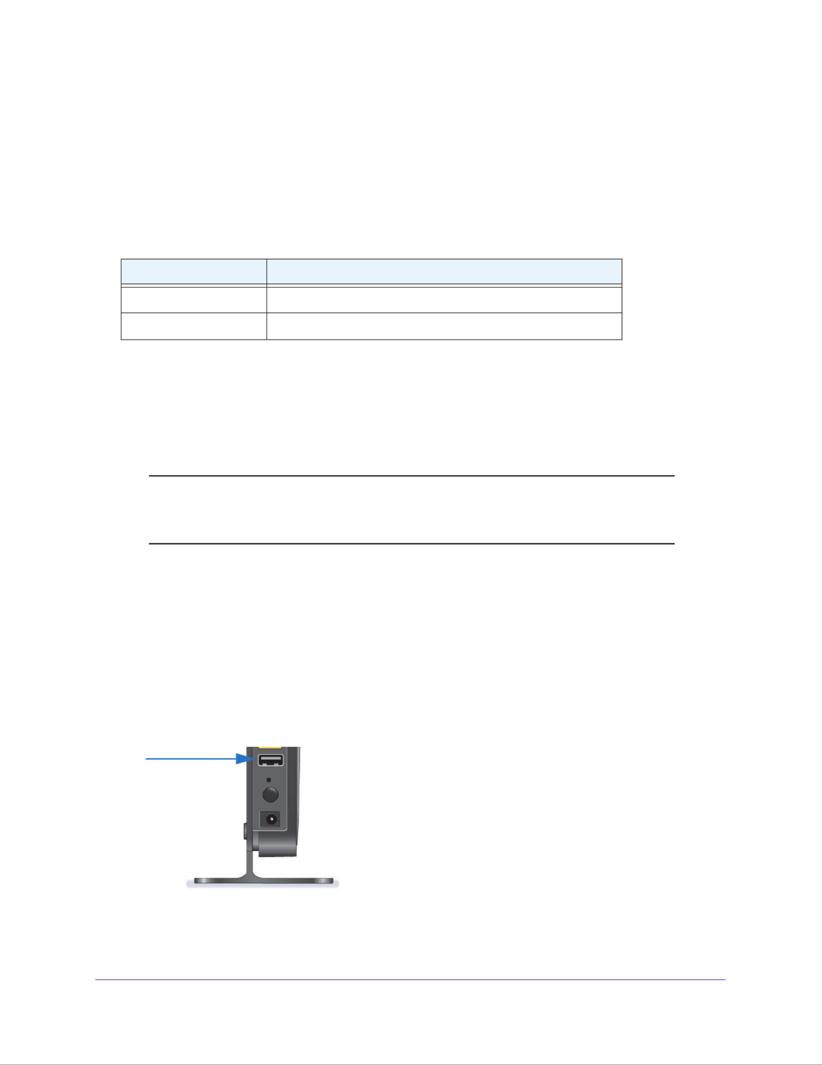
USB Storage
49
N300 Wireless ADSL2+ Modem Router DGN2200v4
USB Drive Requirements
The modem router works with 1.0 and 1.1 (USB Full Speed) and 2.0 (USB High Speed)
standards. The approximate USB bus speeds are shown in the following table. Actual bus
speeds can vary, depending on the CPU speed, memory, speed of the network, and other
variables.
Table 3. USB drive speeds
Bus Speed/Sec
USB 1.1 12 Mbits
USB 2.0 480 Mbits
The modem router works with most USB-compliant external flash and hard drives. For the
most up-to-date list of USB drives that the modem router supports, visit:
http://kbserver.netgear.com/readyshare
The modem router supports both read and write for FAT16, FAT32, NTFS, and Linux file
systems (EXT2).
Note: Some USB external hard drives and flash drives require you to load
the drivers onto the computer before the computer can access the
USB device. Such USB devices do not work with the modem router.
Connect a USB Storage Device to the Modem Router
ReadySHARE lets you access and share or a USB drive connected the modem router USB
port. If your USB device has special drivers, it is not compatible.
To connect a USB storage device:
1. Insert your USB storage device into the USB port on the rear panel of the modem
router.
2. If your USB device has a power supply, you must use it when you connect the USB device
to the modem router.

USB Storage
50
N300 Wireless ADSL2+ Modem Router DGN2200v4
It might take up to 2 minutes before the USB device is ready for sharing.
Safely Remove a USB Drive
If you want to physically disconnect a USB drive from the modem router USB port, first, log in
to the modem router and safely remove it.
To remove a USB disk drive safely:
1. Select .USB Storage > Basic Settings
2. Click the Safely Remove USB Device button.
This takes the drive offline.
3. Physically disconnect the USB drive.
Access the USB Storage Device
When you connect the USB device to the modem router USB port, it might take up to 2
minutes before it is ready for sharing. By default, the USB storage device is available to all
computers on your local area network (LAN).
To access the USB device from a Mac:
1. Select Go > Connect to Server.
2. Enter smb://readyshare as the server address.
3. Click Connect.
To access the USB device from Windows:
Use any of these methods to access the USB device:
•Select . Enter in the dialog box and click .Start > Run \\readyshare OK
•Open a browser and enter in the address bar.\\readyshare
•Open My Network Places and enter in the address bar. \\readyshare
To map the USB device to a Windows network drive:
1. Visit www.netgear.com/readyshare.
2. In the ReadySHARE USB Storage Access pane, click PC Utility.
The readyshareconnect.exe file is downloaded to your computer.
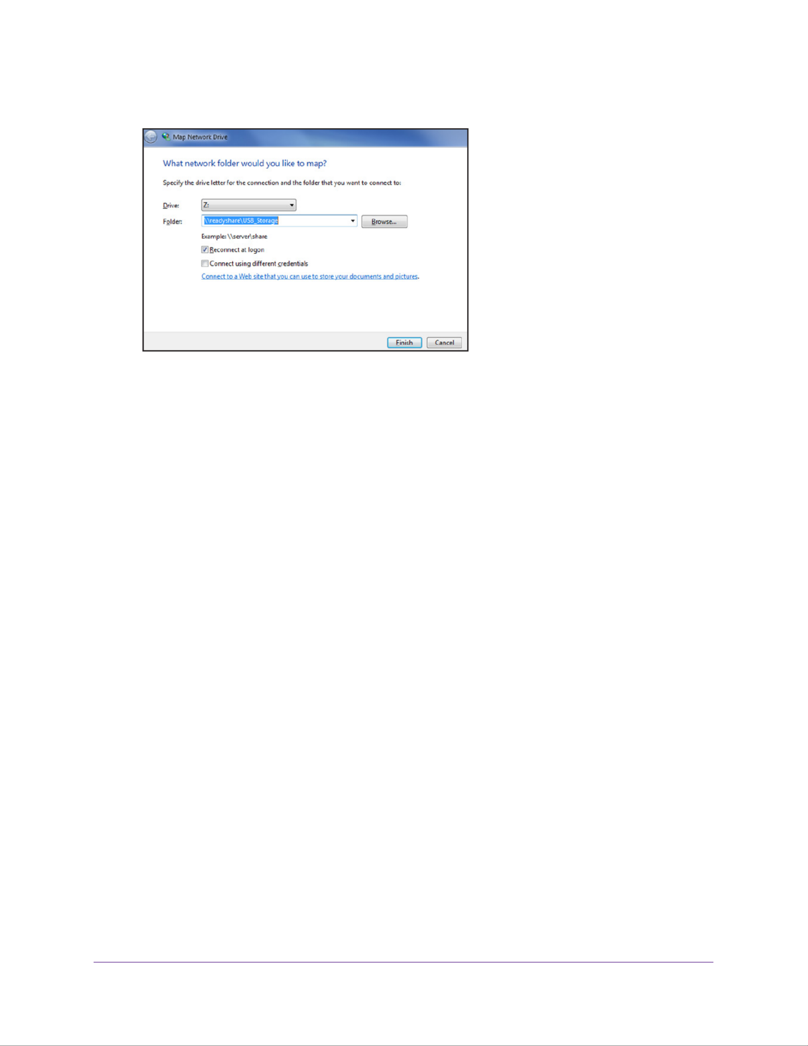
USB Storage
51
N300 Wireless ADSL2+ Modem Router DGN2200v4
3. Launch readyshareconnect.exe.
4. Select the drive letter to map to the network folder.
5. (Optional) If you want to connect to the USB drive as a different user, select the Connect
using different credentials check box.
a. Type the user name and password that you want to use.
b. OKClick .
6. Click Finish.
The USB drive is mapped to the drive letter that you specified.
To access the USB drive from a remote computer:
1. Launch a web browser.
2. Connect using the modem router’s Internet port IP address.
If you are using Dynamic DNS, you can type the DNS name, rather than the IP address.
You can view the modem router’s Internet IP address on the Basic Home screen (see
Dashboard (Basic Home Screen) on page 19).
To access the USB drive with FTP from a remote computer:
1. Make sure that the FTP check box is selected in the Access Method section of the USB
Storage Advanced Settings screen (see USB Storage Device Network and Access
Settings on page 54).
2. Launch a web browser.
3. Type ftp:// and the Internet port IP address in the address field of the browser.
For example, type . ftp://10.1.65.4
If you are using Dynamic DNS, you can type the DNS name rather than the IP address.
4. Type the account name and password for the account that has access rights to the USB
drive.
The user name (account name) for All – no password is . guest

USB Storage
52
N300 Wireless ADSL2+ Modem Router DGN2200v4
The folders on the USB drive that your account has access to display. For example, you
could see: share/partition1/directory1. You can read and copy files from the USB folder.
File-Sharing Scenarios
You can share files on the USB drive for a wide variety of business and recreational
purposes. The files can be any Windows, Mac, or Linux file type including text, Word,
PowerPoint, Excel, MP3, pictures, and multimedia files. USB drive applications include:
•Sharing multimedia with friends and family such as MP3 files, pictures, and other
multimedia with local and remote users.
•Sharing resources on your network. You can store files in a central location so that you do
not have to power up a computer to perform local sharing. In addition, you can share files
between Macintosh, Linux, and Windows computers by using the USB drive as a
go-between across the systems.
•Sharing files such as Word documents, PowerPoint presentations, and text files with
remote users.
A few common uses are described in the following sections.
Share Photos
You can create your own central storage location for photos and multimedia. This method
eliminates the need to log in to (and pay for) an external photo-sharing site.
To share files with your friends and family:
1. Insert your USB drive into the USB port on the modem router either directly or with a
USB cable.
Computers on your local area network (LAN) can automatically access this USB drive
using a web browser or Microsoft Networking.
2. If you want to specify read-only access or to allow access from the Internet, see USB
Storage Device Network and Access Settings on page .54
Store Files in a Central Location for Printing
This scenario is for a family that has one high-quality color printer directly attached to a
computer, but not shared on the local area network (LAN). This family does not have a print
server.
•One family member has photos on a Macintosh computer that she wants to print.
•The photo-capable color printer is directly attached to a PC, but not shared on the
network.
•The Mac and PC are not visible to each other on the network.
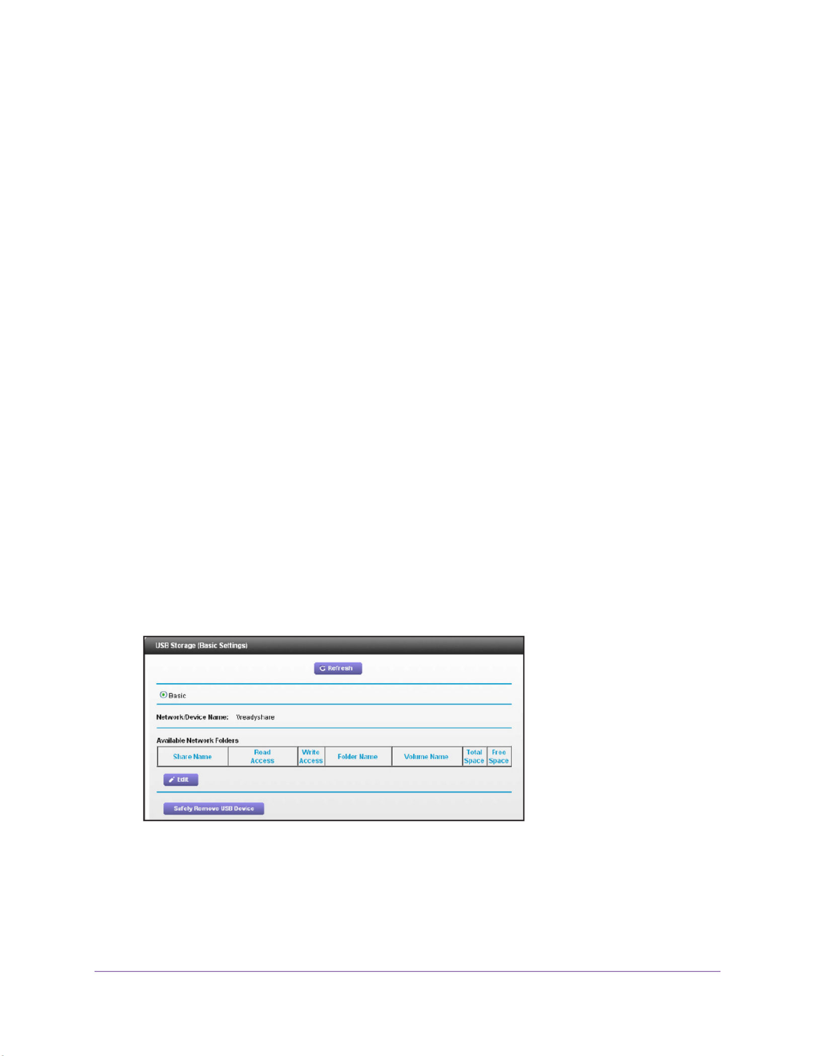
USB Storage
53
N300 Wireless ADSL2+ Modem Router DGN2200v4
To print photos from a Mac on the printer attached to a PC:
1. On the Mac, access the USB drive by typing \\readyshare in the address field of a web
browser. Then copy the photos to the USB drive.
2. On the PC, use a web browser or Microsoft Networking to copy the files from the USB drive
to the PC. Then print the files.
Share Large Files over the Internet
Sending files that are larger than 5 MB can pose a problem for many email systems. The
modem router allows you to share large files such as PowerPoint presentations or .zip files
over the Internet. FTP can be used to download shared files from the modem router.
Sharing files with a remote colleague involves the following considerations:
•There are two user accounts: admin and guest. The password for admin is the same one
that you use to access the modem router. By default, it is . The guest user password
account has no password.
•On the FTP site, the person receiving the files uses the guest user account and enters
the password. (FTP requires that you type something in the password field.)
•Be sure to select the check box in the USB Storage (Advanced FTP (via Internet)
Settings) screen. This option supports both downloading and uploading of files.
You can enable the HTTP (via Internet) option on the USB Storage (Advanced Settings)
screen to share large files. This option supports downloading files only.
View a USB Device Attached to the Modem Router
To view basic information about the USB storage device:
1. Select . Basic > ReadySHARE
By default, the Basic radio button is selected and the screen displays a USB storage
device if it is attached to the modem router USB port.
If you logged in to the modem router before you connected your USB device, you might
not see your USB device in this screen. If this happens, log out and then log back in.

USB Storage
54
N300 Wireless ADSL2+ Modem Router DGN2200v4
2. (Optional) To view the files and folders on the USB device, click the network device name or
the share name.
3. (Optional) To view more detail or to change the USB device settings, click Edit.
The USB Storage (Advanced Settings) screen displays. See USB Storage Device
Network and Access Settings on page 54.
USB Storage Device Network and Access Settings
You can set up the device name, workgroups, and network folders for your USB device.
To view or change the USB storage advanced settings:
1. Select .Advanced > USB Storage > Advanced Settings
2. Specify access to the USB storage device.
•Network Device Name. The default is readyshare. This is the name used to access
the USB device connected to the modem router.
•Workgroup. If you are using a Windows workgroup rather than a domain, the
workgroup name is displayed here. The name works only in an operating system that
supports NetBIOS, such as Microsoft Windows.
•Access Method. Select the check boxes for the access methods that you want.
-Network Neighborhood/MacShare. Enabled by default.
-HTTP. Enabled by default. You can type
http://readyshare.routerlogin.net/shares to access the USB drive.
-HTTP (via Internet. Disabled by default. If you enable this setting, remote users
can type http://<public IP address/shares> (for example, http://1.1.10.102/shares)
or a URL domain name to access the USB drive over the Internet. This feature
supports file uploading only.

USB Storage
55
N300 Wireless ADSL2+ Modem Router DGN2200v4
-FTP. Disabled by default.
-FTP (via Internet). Disabled by default. If you select this feature, remote users
can access the USB drive through FTP over the Internet. This setting supports
both downloading and uploading of files.
3. If you changed the settings, click Apply.
Your changes are saved.
Available Network Folders
You can view or change the network folders on the USB storage device.
To view network folders:
1. Select .Advanced > USB Storage > Advanced Settings
2. Scroll down to the Available Networks Folder section of the screen.
•Share Name. If only one device is connected, the default share name is
USB_Storage. (Some router models have more than one USB port.)
You can click the name, or you can type it in the address field of your web browser. If
Not Shared is shown, the default share has been deleted, and no other share for the
root folder exists. Click the link to change this setting.
•Read Access and Write Access. Shows the permissions and access controls on the
network folder: All - no password (the default) allows all users to access the network
folder. The password for admin is the same one that you use to log in to the modem
router.
•Folder Name. Full path of the network folder.
•Volume Name. Volume name from the storage device (either USB drive or HDD).
•Total Space and Free Space. Shows the current utilization of the storage device.

USB Storage
56
N300 Wireless ADSL2+ Modem Router DGN2200v4
To add a network folder:
1. Select .Advanced > ReadySHARE
2. Click Edit.
3. To add a folder, click Create Network Folder.
If the Add a Network Folder screen does not display, your web browser might be blocking
pop-ups. If it is, then change the browser settings to allow pop-ups.
4. In the Folder field, browse and select the folder.
5. Fill in the Share Name field.
6. In the Read Access list and the Write Access list, select the setting that you want.
The user name (account name) for All – no password is guest. The password for admin is
the same one that is used to log in to the modem router. By default, it is password.
7. Click Apply.
The folder is added on the USB device.
To edit a network folder:
1. Select .Advanced > ReadySHARE
2. Click the Edit button.
The Edit Network Folder screen displays the same settings shown in the Add a Network
Folder screen.
3. Change the settings in the fields as needed.
4. Click Apply.
Your changes are saved.
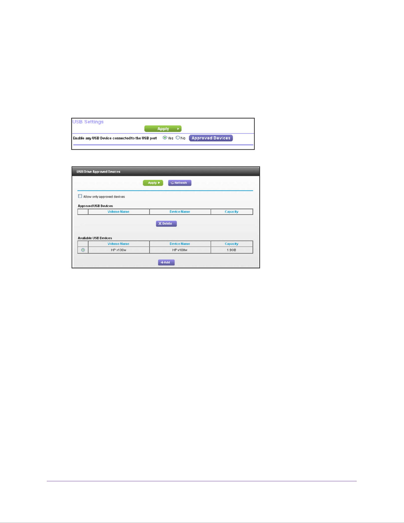
USB Storage
57
N300 Wireless ADSL2+ Modem Router DGN2200v4
Specify Approved USB Devices
For more security, you can set up the modem router to share only approved USB devices.
To set up approved USB devices:
1. Select Advanced > Advanced Setup > USB Settings.
2. Click the Approved Devices button.
This screen shows the approved USB devices and the available USB devices. You can
remove or add approved USB devices.
3. In the Available USB Devices list, select the drive that you want to approve.
4. Click Add.
5. Select the Allow only approved devices check box.
6. Click Apply.
Your change takes effect.
If you want to work with another USB device, first click the Safely Remove USB Device
button for the currently connected USB device. Connect the other USB device, and repeat
this process.

58
6
6. Security
This chapter explains how to use the basic firewall features of the modem router to prevent
objectionable content from reaching the computers and devices on your network.
This chapter includes the following sections:
•Keyword Blocking of HTTP Traffic
•Set Up Firewall Rules to Control Network Access
•Port Triggering to Open Incoming Ports
•Port Forwarding to Permit External Host Communications
•How Port Forwarding Differs from Port Triggering
•Set Up Port Forwarding to Local Servers
•Set Up Port Triggering
•Schedule When to Block the Internet
•Security Event Email Notifications
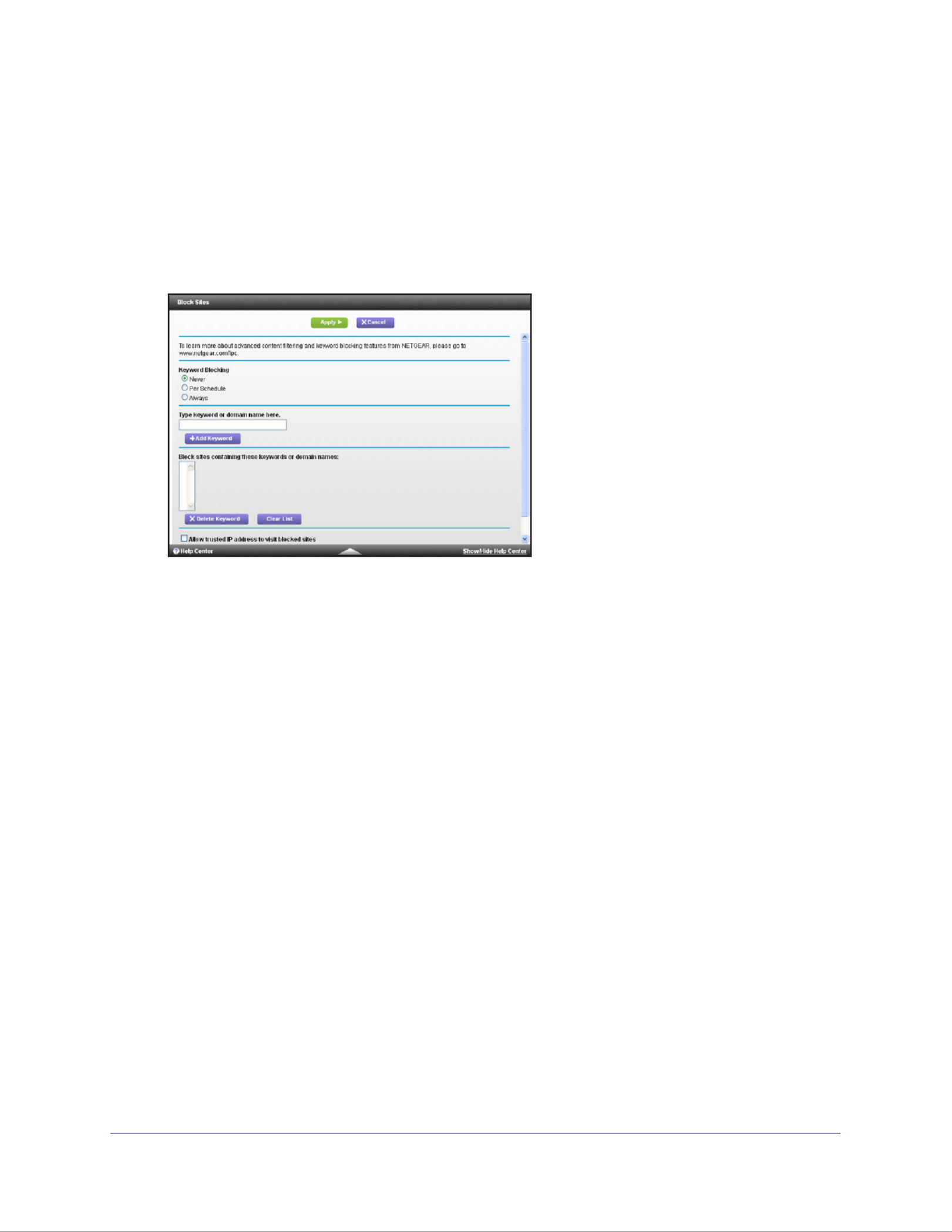
Security
59
N300 Wireless ADSL2+ Modem Router DGN2200v4
Keyword Blocking of HTTP Traffic
Use keyword blocking to prevent certain types of HTTP traffic from accessing your network.
The blocking can be always or according to a schedule.
To set up keyword blocking:
1. Select .Advanced > Security > Block Sites
2. Select one of the keyword blocking options:
•Per Schedule. Turn on keyword blocking according to the Schedule screen settings.
•Always. Turn on keyword blocking all the time, independent of the Schedule screen.
3. In the Keyword field, enter a keyword or domain, click Add Keyword, and click Apply.
The Keyword list supports up to 32 entries. Here are some sample entries:
•Specify XXX to block http://www.badstuff.com/xxx.html.
•Specify .com if you want to allow only sites with domain suf fixes such as .edu or .gov.
•Enter a period ( ) to block all Internet browsing access..
To delete a keyword or domain:
1. Select the keyword you want to delete from the list.
2. Click Delete Keyword.
3. Click Apply.
Your changes are saved.
To specify a trusted computer:
You can exempt one trusted computer from blocking and logging. The computer you exempt
has to have a fixed IP address.
1. In the Trusted IP Address field, enter the IP address.
2. Click Apply.

Security
60
N300 Wireless ADSL2+ Modem Router DGN2200v4
Your changes are saved.
Set Up Firewall Rules to Control Network Access
Your modem router has a firewall that blocks unauthorized access to your wireless network
and permits authorized inbound and outbound communications. Authorized communications
are established according to inbound and outbound rules. The firewall has the following two
default rules
•Inbound. Block all access from outside except responses to requests from the LAN side.
•Outbound. Allow all access from the LAN side to the outside.
You can add rules to further restrict the outbound communications or more widely open the
inbound communications. Exceptions can be based on the service or application, source or
destination IP addresses, and time of day. You can log traffic that matches or does not match
the rule and change the order of rule precedence.
Traffic attempting to pass through the firewall is subjected to the rules in the order shown in
the Rules table from the top (highest precedence) to the bottom. In some cases, the order of
precedence determines which communications are allowed into or out of the network.
To set up firewall rules:
1. Select .Advanced > Security > Firewall Rules
2. You can add, edit, or delete a rule.
•To add an outbound rule, click Add under Outbound Services.
•To edit or delete a rule, select its button on the left side and click or .Edit Delete
3. (Optional) Change the order of precedence:
a. MoveSelect the button on the left side of the rule and click .
b. OKAt the prompt, enter the number of the new position and click .
4. (Optional) To open or close instant messaging, select one of the following radio buttons:
•Close IM Ports. Disables instant messaging traffic.
•Open IM Ports. Enables instant messaging traffic. IM ports are open by default.
5. Click Apply.

Security
61
N300 Wireless ADSL2+ Modem Router DGN2200v4
Your changes are saved.
Port Triggering to Open Incoming Ports
Some application servers (such as FTP and IRC servers) send replies to multiple port
numbers. Using the port triggering function of your modem router, you can tell the modem
router to open more incoming ports when a particular outgoing port originates a session.
An example is Internet Relay Chat (IRC). Your computer connects to an IRC server at
destination port 6667. The IRC server not only responds to your originating source port, but
also sends an “identify” message to your computer on port 113. Using port triggering, you can
tell the modem router, “When you initiate a session with destination port 6667, you have to
also allow incoming traffic on port 113 to reach the originating computer.” Using steps similar
to the preceding example, the following sequence shows the effects of the port triggering rule
you have defined:
1. You open an IRC client program to start a chat session on your computer.
2. Your IRC client composes a request message to an IRC server using a destination port
number of 6667, the standard port number for an IRC server process. Your computer then
sends this request message to your modem router.
3. Your modem router creates an entry in its internal session table describing this
communication session between your computer and the IRC server. Your modem router
stores the original information, performs Network Address Translation (NAT) on the source
address and port, and sends this request message through the Internet to the IRC server.
4. Noting your port triggering rule and having observed the destination port number of 6667,
your modem router creates an additional session entry to send any incoming port 113 traffic
to your computer.
5. The IRC server sends a return message to your modem router using the NAT-assigned
source port (for example, port 33333) as the destination port. The IRC server also sends an
“identify” message to your modem router with destination port 113.
6. Upon receiving the incoming message to destination port 33333, your modem router
checks its session table to determine whether there is an active session for port number
33333. Finding an active session, the modem router restores the original address
information replaced by NAT and sends this reply message to your computer.
7. Upon receiving the incoming message to destination port 113, your modem router checks
its session table and learns that there is an active session for port 113, associated with your
computer. The modem router replaces the message’s destination IP address with your
computer’s IP address and forwards the message to your computer.
8. When you finish your chat session, your eventually senses a period of modem router
inactivity in the communications. The modem router then removes the session information
from its session table, and incoming traffic is no longer accepted on port numbers 33333 or
113.
To configure port triggering, you need to know which inbound ports the application needs.
Also, you need to know the number of the outbound port that will trigger the opening of the
inbound ports. You can usually determine this information by contacting the publisher of the
application or the relevant user groups or news groups.

Security
62
N300 Wireless ADSL2+ Modem Router DGN2200v4
Only one computer at a time can use the triggered application.
Port Forwarding to Permit External Host Communications
In both of the preceding examples, your computer initiates an application session with a
server computer on the Internet. However, you might need to allow a client computer on the
Internet to initiate a connection to a server computer on your network. Normally, your modem
router ignores any inbound traffic that is not a response to your own outbound traffic. You can
configure exceptions to this default rule by using the port forwarding feature.
A typical application of port forwarding can be shown by reversing the client-server
relationship from the previous web server example. In this case, a remote computer’s
browser needs to access a web server running on a computer in your local network. Using
port forwarding, you can tell the modem router, “When you receive incoming traffic on port 80
(the standard port number for a web server process), forward it to the local computer at
192.168.0.123.” The following sequence shows the effects of the port forwarding rule you
have defined:
1. The user of a remote computer opens a browser and requests a web page from
www.example.com, which resolves to the public IP address of your modem router. The
remote computer composes a web page request message with the following destination
information:
Destination address. The IP address of www.example.com, which is the address of your
modem router.
Destination port number. 80, which is the standard port number for a web server
process.
The remote computer then sends this request message through the Internet to your
modem router.
2. Your modem router receives the request message and looks in its rules table for any rules
covering the disposition of incoming port 80 traffic. Your port forwarding rule specifies that
incoming port 80 traffic should be forwarded to local IP address 192.168.0.123. Therefore,
your modem router modifies the destination information in the request message:
The destination address is replaced with 192.168.0.123.
Your modem router then sends this request message to your local network.
3. Your web server at 192.168.0.123 receives the request and composes a return message
with the requested web page data. Your web server then sends this reply message to your
modem router.
4. Your modem router performs Network Address Translation (NAT) on the source IP address,
and sends this request message through the Internet to the remote computer, which
displays the web page from www.example.com.
To configure port forwarding, you need to know which inbound ports the application needs.
You usually can determine this information by contacting the publisher of the application or
the relevant user groups or news groups.
Produkt Specifikationer
| Mærke: | Netgear |
| Kategori: | Router |
| Model: | DGN2200v4 |
Har du brug for hjælp?
Hvis du har brug for hjælp til Netgear DGN2200v4 stil et spørgsmål nedenfor, og andre brugere vil svare dig
Router Netgear Manualer

12 Januar 2025
15 Oktober 2024
10 Oktober 2024
10 Oktober 2024
7 Oktober 2024
2 Oktober 2024
18 September 2024
18 September 2024
17 September 2024
11 September 2024
Router Manualer
- Router QNAP
- Router Nilox
- Router Bosch
- Router Acer
- Router TCL
- Router Aruba
- Router Siemens
- Router Netis
- Router Samsung
- Router Metabo
- Router DeWalt
- Router TP-Link
- Router Silverline
- Router IFM
- Router AT&T
- Router Apple
- Router Google
- Router Technaxx
- Router HP
- Router Makita
- Router D-Link
- Router Motorola
- Router Roland
- Router Asus
- Router Gigabyte
- Router Güde
- Router AVM
- Router Planet
- Router Hama
- Router Thomson
- Router Milwaukee
- Router Nokia
- Router Belkin
- Router Edimax
- Router Black Box
- Router Clas Ohlson
- Router Strong
- Router TRENDnet
- Router Trust
- Router Topcom
- Router Black And Decker
- Router Einhell
- Router Hikoki
- Router Hitachi
- Router Buffalo
- Router Medion
- Router Sweex
- Router Vivanco
- Router Linksys
- Router Festool
- Router Cisco
- Router EZVIZ
- Router Huawei
- Router König
- Router Technicolor
- Router Gembird
- Router EnVivo
- Router Totolink
- Router Nest
- Router Vtech
- Router BenQ
- Router Powerplus
- Router Alcatel
- Router Western Digital
- Router Anker
- Router Digitus
- Router Zebra
- Router Thrustmaster
- Router Xiaomi
- Router Techly
- Router Dell
- Router Schneider
- Router Kopul
- Router MSI
- Router NEC
- Router Nexxt
- Router APC
- Router Foscam
- Router Kathrein
- Router Kyocera
- Router Sonos
- Router AJA
- Router LevelOne
- Router Mercusys
- Router Zoom
- Router Porter-Cable
- Router JUNG
- Router ZyXEL
- Router Sagem
- Router Tenda
- Router Vodafone
- Router Synology
- Router Hikvision
- Router Ubiquiti Networks
- Router Cotech
- Router EnGenius
- Router Devolo
- Router Patton
- Router Renkforce
- Router Kraun
- Router Manhattan
- Router ZTE
- Router Mikrotik
- Router Aztech
- Router LogiLink
- Router Alfa
- Router Eminent
- Router Kramer
- Router BT
- Router Hercules
- Router Evolution
- Router MuxLab
- Router Phicomm
- Router Telstra
- Router Upvel
- Router Arris
- Router Milan
- Router Xantech
- Router Mercku
- Router Kasda
- Router Iogear
- Router Digi
- Router ATen
- Router Vimar
- Router Smart-AVI
- Router Dahua Technology
- Router StarTech.com
- Router Draytek
- Router Conceptronic
- Router Rocstor
- Router Teltonika
- Router Toolcraft
- Router SPL
- Router Lindy
- Router Kogan
- Router AVMATRIX
- Router Barco
- Router Peak
- Router Lumantek
- Router Lancom
- Router FSR
- Router RAVPower
- Router Sitecom
- Router Intellinet
- Router Holzmann
- Router Ocean Matrix
- Router Comprehensive
- Router Intelix
- Router Digitalinx
- Router Alfatron
- Router Media-Tech
- Router BZBGear
- Router Key Digital
- Router KanexPro
- Router Gefen
- Router RGBlink
- Router Moxa
- Router Bea-fon
- Router Blustream
- Router WyreStorm
- Router Allnet
- Router Allied Telesis
- Router Airlive
- Router Actiontec
- Router Proximus
- Router KPN
- Router ICIDU
- Router Verizon
- Router Billion
- Router T-Mobile
- Router Hawking Technologies
- Router Beafon
- Router Zolid
- Router Sagemcom
- Router SIIG
- Router Eero
- Router Advantech
- Router Approx
- Router Arcadyan
- Router Digiconnect
- Router Ubee
- Router SMC
- Router Tele 2
- Router Cambium Networks
- Router CradlePoint
- Router ModeCom
- Router Extreme Networks
- Router Davolink
- Router Sixnet
- Router 7inova
- Router AVPro Edge
- Router Cudy
- Router Kiloview
- Router F-Secure
- Router Mach Power
- Router Rosewill
- Router Digicom
- Router Sabrent
- Router On Networks
- Router Atlona
- Router PENTAGRAM
- Router Leoxsys
- Router Readynet
- Router OneAccess
- Router Accelerated
- Router Nexaira
- Router Hamlet
- Router T-com
- Router A-NeuVideo
- Router Amped Wireless
- Router 3Com
- Router I-Tec
- Router Avenview
- Router Ruckus Wireless
- Router Dovado
- Router StarIink
- Router EXSYS
- Router NetComm
- Router Juniper
- Router Comtrend
- Router Premiertek
- Router GL.iNet
- Router Shinybow
- Router Edgewater
- Router Atlantis Land
- Router Lantronix
- Router Keenetic
- Router Starlink
- Router Keewifi
- Router Milesight
- Router PulseAudio
- Router Predator
- Router Luxul
- Router DVDO
- Router Silentwind
- Router Keezel
- Router United Telecom
- Router Wisetiger
- Router Zurn
- Router Digital Forecast
Nyeste Router Manualer

8 April 2025
22 Marts 2025
9 Marts 2025
6 Marts 2025

23 Februar 2025
23 Februar 2025

22 Februar 2025
20 Februar 2025
20 Februar 2025
12 Februar 2025