Netgear GS308T Manual
Læs nedenfor 📖 manual på dansk for Netgear GS308T (362 sider) i kategorien Skifte. Denne guide var nyttig for 29 personer og blev bedømt med 4.5 stjerner i gennemsnit af 2 brugere
Side 1/362

NETGEAR, Inc.
350 East Plumeria Drive
San Jose, CA 95134, USA
November 2019
202-11890-02
User Manual
S350 Series 8-Port Gigabit Ethernet Smart
Managed Pro Switch
User Manual
Models
GS308T
GS310TP

S350 Series 8-Port Gigabit Ethernet Smart Managed Pro Switch Models GS308T and GS310TP
User Manual2
Support
Thank you for purchasing this NETGEAR product. You can visit https://www.netgear.com/support/ to register your
product, get help, access the latest downloads and user manuals, and join our community. We recommend that you
use only official NETGEAR support resources
Compliance and Conformity
For regulatory compliance information including the EU Declaration of Conformity, visit
https://www.netgear.com/about/regulatory/.
See the regulatory compliance document before connecting the power supply.
Do not use this device outdoors. If you connect cables or devices that are outdoors to this device, see
http://kb.netgear.com/000057103 for safety and warranty information.
Trademarks
© NETGEAR, Inc., NETGEAR, and the NETGEAR Logo are trademarks of NETGEAR, Inc. Any non-NETGEAR
trademarks are used for reference purposes only.
Revision History
Publication
Part Number Publish Date Comments
202-11890-02 November 2019 We made changes to the information in and the organization of Chapter 1, Get
Started and Chapter 5, Manage Device Security.
We made multiple other minor changes and minor corrections in the manual.
We published the manual in a new format.
202-11890-01 January 2019 First publication

3
Contents
Chapter 1 Get Started
Available Publications . . . . . . . . . . . . . . . . . . . . . . . . . . . . . . . . . . . . . . . . . . . . 10
Switch Management and Discovery Overview . . . . . . . . . . . . . . . . . . . . . . .11
Options to Change the Default IP Address of the Switch . . . . . . . . . . . . . . 11
Discover or Change the Switch IP Address . . . . . . . . . . . . . . . . . . . . . . . . . . 12
Discover the Switch in a Network With a DHCP Server. . . . . . . . . . . . . .12
Discover the Switch in a Network Without a DHCP Server. . . . . . . . . . .13
Use the NETGEAR Switch Discovery Tool to Access the Switch. . . . . . .15
Use the NETGEAR Insight Mobile App to Discover the Switch . . . . . . .16
Configure a Static IP Address From a Directly Connected Computer .16
About the User Interfaces . . . . . . . . . . . . . . . . . . . . . . . . . . . . . . . . . . . . . . . . . 18
Software Requirements to Use the Local Browser Interface. . . . . . . . . .18
Supported Web Browsers . . . . . . . . . . . . . . . . . . . . . . . . . . . . . . . . . . . . . .18
Access the Local Browser Interface . . . . . . . . . . . . . . . . . . . . . . . . . . . . . . . . . 19
Navigation Tabs, Configuration Menus, and Page Menu . . . . . . . . . . . .21
Configuration and Status Options . . . . . . . . . . . . . . . . . . . . . . . . . . . . . . .21
Buttons in the Local Browser Interface. . . . . . . . . . . . . . . . . . . . . . . . . . . .21
User-Defined Fields. . . . . . . . . . . . . . . . . . . . . . . . . . . . . . . . . . . . . . . . . . . .22
Change the Language of the Local Browser Interface . . . . . . . . . . . . . . . . . 22
Use the Device View of the Local Browser Interface . . . . . . . . . . . . . . . . . . . 23
Power LED in the Device View. . . . . . . . . . . . . . . . . . . . . . . . . . . . . . . . . . .25
PoE Max LED in the Device View (Model GS310TP) . . . . . . . . . . . . . . . .25
Interface Naming Conventions. . . . . . . . . . . . . . . . . . . . . . . . . . . . . . . . . . . . . 25
Configure Interface Settings . . . . . . . . . . . . . . . . . . . . . . . . . . . . . . . . . . . . . . . 26
Context-Sensitive Help and Access to the Support WebSite . . . . . . . . . . . 29
Access the User Guide Online . . . . . . . . . . . . . . . . . . . . . . . . . . . . . . . . . . . . .30
Register Your Product. . . . . . . . . . . . . . . . . . . . . . . . . . . . . . . . . . . . . . . . . . . . . 30
Chapter 2 Configure System Information
View and Configure the Switch Management Settings . . . . . . . . . . . . . . . .32
View or Define System Information . . . . . . . . . . . . . . . . . . . . . . . . . . . . . .32
View the System CPU Status . . . . . . . . . . . . . . . . . . . . . . . . . . . . . . . . . . . .34
Configure the IP Network and VLAN Settings for the
Local Browser Interface . . . . . . . . . . . . . . . . . . . . . . . . . . . . . . . . . . . . . . . .37
Configure the Time Settings . . . . . . . . . . . . . . . . . . . . . . . . . . . . . . . . . . . .39
Configure Denial of Service Settings . . . . . . . . . . . . . . . . . . . . . . . . . . . . .53
Configure DNS Settings . . . . . . . . . . . . . . . . . . . . . . . . . . . . . . . . . . . . . . . .56
Configure Green Ethernet Settings . . . . . . . . . . . . . . . . . . . . . . . . . . . . . .60
Use the Device View. . . . . . . . . . . . . . . . . . . . . . . . . . . . . . . . . . . . . . . . . . . . . . 63

S350 Series 8-Port Gigabit Ethernet Smart Managed Pro Switch Models GS308T and GS310TP
User Manual4
Configure PoE . . . . . . . . . . . . . . . . . . . . . . . . . . . . . . . . . . . . . . . . . . . . . . . . . . . 63
Configure the Global PoE Settings . . . . . . . . . . . . . . . . . . . . . . . . . . . . . . .63
Configure the PoE Port Settings . . . . . . . . . . . . . . . . . . . . . . . . . . . . . . . . .64
Configure SNMP . . . . . . . . . . . . . . . . . . . . . . . . . . . . . . . . . . . . . . . . . . . . . . . . . 68
Configure the SNMPv1/v2 Community . . . . . . . . . . . . . . . . . . . . . . . . . . .68
Configure SNMPv1/v2 Trap Settings . . . . . . . . . . . . . . . . . . . . . . . . . . . . .70
Configure SNMPv1/v2 Trap Flags. . . . . . . . . . . . . . . . . . . . . . . . . . . . . . . .73
View the Supported MIBs. . . . . . . . . . . . . . . . . . . . . . . . . . . . . . . . . . . . . . .74
Configure SNMP V3 Users . . . . . . . . . . . . . . . . . . . . . . . . . . . . . . . . . . . . . .75
Configure LLDP. . . . . . . . . . . . . . . . . . . . . . . . . . . . . . . . . . . . . . . . . . . . . . . . . . 76
Configure LLDP Global Settings . . . . . . . . . . . . . . . . . . . . . . . . . . . . . . . . .76
Configure LLDP Port Settings . . . . . . . . . . . . . . . . . . . . . . . . . . . . . . . . . . .78
View the LLDP-MED Network Policy . . . . . . . . . . . . . . . . . . . . . . . . . . . . . .79
Configure LLDP-MED Port Settings . . . . . . . . . . . . . . . . . . . . . . . . . . . . . .81
View the Local Information Advertised Through LLDP . . . . . . . . . . . . . .82
View LLDP Neighbors Information . . . . . . . . . . . . . . . . . . . . . . . . . . . . . . .84
Configure DHCP Snooping. . . . . . . . . . . . . . . . . . . . . . . . . . . . . . . . . . . . . . . . 87
Configure the Global DHCP Snooping Settings . . . . . . . . . . . . . . . . . . .88
Enable DHCP for All Interfaces in a VLAN . . . . . . . . . . . . . . . . . . . . . . . . .89
Configure DHCP Snooping Interface Settings . . . . . . . . . . . . . . . . . . . . .89
Configure Static DHCP Bindings. . . . . . . . . . . . . . . . . . . . . . . . . . . . . . . . .91
Configure DHCP Snooping Persistent Settings . . . . . . . . . . . . . . . . . . . .92
View or Clear DHCP Snooping Statistics . . . . . . . . . . . . . . . . . . . . . . . . . .93
Set Up PoE Timer Schedules. . . . . . . . . . . . . . . . . . . . . . . . . . . . . . . . . . . . . . . 94
Create a PoE Timer Schedule . . . . . . . . . . . . . . . . . . . . . . . . . . . . . . . . . . .95
Specify the Settings for an Absolute PoE Timer Schedule . . . . . . . . . . .95
Specify the Settings for a Recurring PoE Timer Schedule. . . . . . . . . . . .97
Change the Settings for a Recurring PoE Timer Schedule Entry . . . . . .99
Delete a PoE Timer Schedule Entry . . . . . . . . . . . . . . . . . . . . . . . . . . . . 100
Delete a PoE Timer Schedule . . . . . . . . . . . . . . . . . . . . . . . . . . . . . . . . . 100
Chapter 3 Configure Switching
Configure the Port Settings and Maximum Frame Size . . . . . . . . . . . . . . 103
Configure Link Aggregation Groups . . . . . . . . . . . . . . . . . . . . . . . . . . . . . . .106
Configure LAG Settings . . . . . . . . . . . . . . . . . . . . . . . . . . . . . . . . . . . . . . 106
Configure LAG Membership . . . . . . . . . . . . . . . . . . . . . . . . . . . . . . . . . . 108
Set the LACP System Priority . . . . . . . . . . . . . . . . . . . . . . . . . . . . . . . . . . 109
Set the LACP Port Priority Settings . . . . . . . . . . . . . . . . . . . . . . . . . . . . . 110
Configure VLANs . . . . . . . . . . . . . . . . . . . . . . . . . . . . . . . . . . . . . . . . . . . . . . .111
Configure VLAN Settings . . . . . . . . . . . . . . . . . . . . . . . . . . . . . . . . . . . . . 112
Configure VLAN Membership. . . . . . . . . . . . . . . . . . . . . . . . . . . . . . . . . 115
View the VLAN Status . . . . . . . . . . . . . . . . . . . . . . . . . . . . . . . . . . . . . . . . 117
Configure Port PVID Settings. . . . . . . . . . . . . . . . . . . . . . . . . . . . . . . . . . 118
Configure a MAC-Based VLAN . . . . . . . . . . . . . . . . . . . . . . . . . . . . . . . . 120
Configure Protocol-Based VLAN Groups . . . . . . . . . . . . . . . . . . . . . . . 122
Configure Protocol-Based VLAN Group Membership . . . . . . . . . . . . 123
Configure a Voice VLAN . . . . . . . . . . . . . . . . . . . . . . . . . . . . . . . . . . . . . . . . .125

S350 Series 8-Port Gigabit Ethernet Smart Managed Pro Switch Models GS308T and GS310TP
User Manual5
Configure Auto-VoIP. . . . . . . . . . . . . . . . . . . . . . . . . . . . . . . . . . . . . . . . . . . . .126
Configure Protocol-Based Port Settings for VoIP . . . . . . . . . . . . . . . . . 127
Configure Auto-VoIP OUI-Based Properties . . . . . . . . . . . . . . . . . . . . . 128
Configure the OUI-Based Port Settings . . . . . . . . . . . . . . . . . . . . . . . . . 129
Manage the OUI Table . . . . . . . . . . . . . . . . . . . . . . . . . . . . . . . . . . . . . . . 130
Display the Auto-VoIP Status . . . . . . . . . . . . . . . . . . . . . . . . . . . . . . . . . . 132
Configure Spanning Tree Protocol . . . . . . . . . . . . . . . . . . . . . . . . . . . . . . . 133
Configure the STP Settings and View the STP Status. . . . . . . . . . . . . . 133
Configure and View the CST Settings . . . . . . . . . . . . . . . . . . . . . . . . . . 135
Configure and View the CST Port Settings . . . . . . . . . . . . . . . . . . . . . . 137
View the CST Port Status. . . . . . . . . . . . . . . . . . . . . . . . . . . . . . . . . . . . . . 139
View Rapid STP Information. . . . . . . . . . . . . . . . . . . . . . . . . . . . . . . . . . . 141
Manage MST Settings . . . . . . . . . . . . . . . . . . . . . . . . . . . . . . . . . . . . . . . . 142
Configure and View the Port Settings for an MST Instance. . . . . . . . . 144
View the STP Statistics. . . . . . . . . . . . . . . . . . . . . . . . . . . . . . . . . . . . . . . . 147
Configure Multicast . . . . . . . . . . . . . . . . . . . . . . . . . . . . . . . . . . . . . . . . . . . . .148
View and Search the MFDB Table . . . . . . . . . . . . . . . . . . . . . . . . . . . . . . 148
View the MFDB Statistics . . . . . . . . . . . . . . . . . . . . . . . . . . . . . . . . . . . . . 149
Configure the Auto-Video Multicast Settings . . . . . . . . . . . . . . . . . . . . 150
About IGMP Snooping . . . . . . . . . . . . . . . . . . . . . . . . . . . . . . . . . . . . . . . 151
Configure IGMP Snooping. . . . . . . . . . . . . . . . . . . . . . . . . . . . . . . . . . . . 151
Configure IGMP Snooping for Interfaces . . . . . . . . . . . . . . . . . . . . . . . 153
View, Search, or Clear the IGMP Snooping Table . . . . . . . . . . . . . . . . 155
Configure IGMP Snooping for VLANs . . . . . . . . . . . . . . . . . . . . . . . . . . 156
Modify IGMP Snooping Settings for a VLAN. . . . . . . . . . . . . . . . . . . . . 157
Disable IGMP Snooping on a VLAN . . . . . . . . . . . . . . . . . . . . . . . . . . . . 158
Configure a Multicast Router Interface . . . . . . . . . . . . . . . . . . . . . . . . . 159
Configure a Multicast Router VLAN . . . . . . . . . . . . . . . . . . . . . . . . . . . . 160
IGMP Snooping Querier Overview. . . . . . . . . . . . . . . . . . . . . . . . . . . . . 161
Configure an IGMP Snooping Querier . . . . . . . . . . . . . . . . . . . . . . . . . 161
Configure an IGMP Snooping Querier for VLANs . . . . . . . . . . . . . . . . 162
Display IGMP Snooping Querier for VLAN Status . . . . . . . . . . . . . . . . 163
View, Search, and Manage the MAC Address Table . . . . . . . . . . . . . . . . . .165
View, Search, or Clear the MAC Address Table . . . . . . . . . . . . . . . . . . 165
Set the Dynamic Address Aging Interval. . . . . . . . . . . . . . . . . . . . . . . . 167
Add a Static MAC Address to the MAC Address Table . . . . . . . . . . . . 168
Configure Layer 2 Loop Protection . . . . . . . . . . . . . . . . . . . . . . . . . . . . . . . .169
Configure Global Layer 2 Loop Protection . . . . . . . . . . . . . . . . . . . . . . 169
View and Configure Layer 2 Loop Protection on a Port. . . . . . . . . . . . 170
Chapter 4 Configure Quality of Service
Quality of Service Concepts. . . . . . . . . . . . . . . . . . . . . . . . . . . . . . . . . . . . . 174
Manage Class of Service . . . . . . . . . . . . . . . . . . . . . . . . . . . . . . . . . . . . . . . . .174
CoS Configuration Concepts. . . . . . . . . . . . . . . . . . . . . . . . . . . . . . . . . . 174
Configure Global CoS Settings . . . . . . . . . . . . . . . . . . . . . . . . . . . . . . . . 175
Configure CoS Interface Settings for an Interface . . . . . . . . . . . . . . . . 176
Configure CoS Queue Settings for an Interface. . . . . . . . . . . . . . . . . . 178
Map 802.1p Priorities to Queues . . . . . . . . . . . . . . . . . . . . . . . . . . . . . . 179

S350 Series 8-Port Gigabit Ethernet Smart Managed Pro Switch Models GS308T and GS310TP
User Manual6
Map DSCP Values to Queues . . . . . . . . . . . . . . . . . . . . . . . . . . . . . . . . . 181
Manage Differentiated Services . . . . . . . . . . . . . . . . . . . . . . . . . . . . . . . . . . .182
Defining DiffServ . . . . . . . . . . . . . . . . . . . . . . . . . . . . . . . . . . . . . . . . . . . . 182
Configure and Display Global DiffServ Settings. . . . . . . . . . . . . . . . . . 183
Configure a DiffServ Class . . . . . . . . . . . . . . . . . . . . . . . . . . . . . . . . . . . . 184
Configure a DiffServ Policy. . . . . . . . . . . . . . . . . . . . . . . . . . . . . . . . . . . . 190
Configure the DiffServ Service Interface . . . . . . . . . . . . . . . . . . . . . . . . 195
View DiffServ Service Statistics . . . . . . . . . . . . . . . . . . . . . . . . . . . . . . . . 197
Chapter 5 Manage Device Security
Configure the Management Security Settings . . . . . . . . . . . . . . . . . . . . . 200
Change the Password for the Local Browser Interface . . . . . . . . . . . . 200
Manage the RADIUS Settings . . . . . . . . . . . . . . . . . . . . . . . . . . . . . . . . . 201
Configure TACACS+ . . . . . . . . . . . . . . . . . . . . . . . . . . . . . . . . . . . . . . . . . 210
Configure Authentication Lists . . . . . . . . . . . . . . . . . . . . . . . . . . . . . . . . 213
Manage the Smart Control Center Utility . . . . . . . . . . . . . . . . . . . . . . . 217
Configure Management Access. . . . . . . . . . . . . . . . . . . . . . . . . . . . . . . . . . .218
Configure HTTP Access Settings. . . . . . . . . . . . . . . . . . . . . . . . . . . . . . . 218
Configure HTTPS Access Settings . . . . . . . . . . . . . . . . . . . . . . . . . . . . . 219
Manage Certificates for HTTPS Access . . . . . . . . . . . . . . . . . . . . . . . . . 221
Transfer an Existing Certificate to the Switch . . . . . . . . . . . . . . . . . . . . 223
Manage Access Control to the Switch . . . . . . . . . . . . . . . . . . . . . . . . . . 225
Configure Port Authentication . . . . . . . . . . . . . . . . . . . . . . . . . . . . . . . . . . . .231
Configure Global 802.1X Settings . . . . . . . . . . . . . . . . . . . . . . . . . . . . . 232
Manage Port Authentication on Individual Ports . . . . . . . . . . . . . . . . . 233
View the Port Summary. . . . . . . . . . . . . . . . . . . . . . . . . . . . . . . . . . . . . . . 238
View the Client Summary . . . . . . . . . . . . . . . . . . . . . . . . . . . . . . . . . . . . . 239
Set Up Traffic Control . . . . . . . . . . . . . . . . . . . . . . . . . . . . . . . . . . . . . . . . . . 241
Manage MAC Filtering . . . . . . . . . . . . . . . . . . . . . . . . . . . . . . . . . . . . . . . 241
MAC Filter Summary . . . . . . . . . . . . . . . . . . . . . . . . . . . . . . . . . . . . . . . . . 243
Configure Storm Control Settings . . . . . . . . . . . . . . . . . . . . . . . . . . . . . 244
Manage Port Security . . . . . . . . . . . . . . . . . . . . . . . . . . . . . . . . . . . . . . . . 248
Configure Protected Ports . . . . . . . . . . . . . . . . . . . . . . . . . . . . . . . . . . . . 252
Configure Access Control Lists. . . . . . . . . . . . . . . . . . . . . . . . . . . . . . . . . . . .253
Use the ACL Wizard to Create a Simple ACL . . . . . . . . . . . . . . . . . . . . 253
Configure a Basic MAC ACL . . . . . . . . . . . . . . . . . . . . . . . . . . . . . . . . . . 258
Configure MAC ACL Rules . . . . . . . . . . . . . . . . . . . . . . . . . . . . . . . . . . . . 261
Configure MAC Bindings . . . . . . . . . . . . . . . . . . . . . . . . . . . . . . . . . . . . . 265
View or Delete MAC ACL Bindings in the MAC Binding Table . . . . . 267
Configure a Basic or Extended IP ACL. . . . . . . . . . . . . . . . . . . . . . . . . . 268
Configure Rules for a Basic IP ACL . . . . . . . . . . . . . . . . . . . . . . . . . . . . . 271
Configure Rules for an Extended IP ACL . . . . . . . . . . . . . . . . . . . . . . . . 275
Configure IP ACL Interface Bindings . . . . . . . . . . . . . . . . . . . . . . . . . . . 282
View or Delete IP ACL Bindings in the IP ACL Binding Table . . . . . . . 284
Configure VLAN ACL Bindings . . . . . . . . . . . . . . . . . . . . . . . . . . . . . . . . 285

S350 Series 8-Port Gigabit Ethernet Smart Managed Pro Switch Models GS308T and GS310TP
User Manual7
Chapter 6 Monitor the System
Monitor the Switch and the Ports . . . . . . . . . . . . . . . . . . . . . . . . . . . . . . . . 289
View Switch Statistics . . . . . . . . . . . . . . . . . . . . . . . . . . . . . . . . . . . . . . . . 289
View Port Statistics . . . . . . . . . . . . . . . . . . . . . . . . . . . . . . . . . . . . . . . . . . . 292
View and Manage Detailed Port Statistics . . . . . . . . . . . . . . . . . . . . . . . . . 295
View or Clear EAP and EAPoL Statistics . . . . . . . . . . . . . . . . . . . . . . . . . 301
Perform a Cable Test . . . . . . . . . . . . . . . . . . . . . . . . . . . . . . . . . . . . . . . . . 302
Configure and View Logs . . . . . . . . . . . . . . . . . . . . . . . . . . . . . . . . . . . . . . . .304
Manage the Memory Logs . . . . . . . . . . . . . . . . . . . . . . . . . . . . . . . . . . . . 304
Manage the Flash Log . . . . . . . . . . . . . . . . . . . . . . . . . . . . . . . . . . . . . . . 306
Manage the Server Log . . . . . . . . . . . . . . . . . . . . . . . . . . . . . . . . . . . . . . 307
View or Clear the Trap Logs and the Counters . . . . . . . . . . . . . . . . . . . 310
Configure Port Mirroring . . . . . . . . . . . . . . . . . . . . . . . . . . . . . . . . . . . . . . . . .312
Chapter 7 Maintenance
Reboot the Switch . . . . . . . . . . . . . . . . . . . . . . . . . . . . . . . . . . . . . . . . . . . . . 316
Reset the Switch to Its Factory Default Settings . . . . . . . . . . . . . . . . . . . . . .317
Export a File From the Switch . . . . . . . . . . . . . . . . . . . . . . . . . . . . . . . . . . . . .318
Use TFTP to Export a File From the Switch to a TFTP Server . . . . . . . 318
Use HTTP to Export a File from the Switch to a Computer . . . . . . . . . 320
Download a File to the Switch or Update the Firmware. . . . . . . . . . . . . . .321
Use TFTP to Download a File to the Switch or Update the
Software Image . . . . . . . . . . . . . . . . . . . . . . . . . . . . . . . . . . . . . . . . . . . . . 321
Use HTTP to Download a File to the Switch or Update the
Software Image . . . . . . . . . . . . . . . . . . . . . . . . . . . . . . . . . . . . . . . . . . . . . 323
Manage Software Images . . . . . . . . . . . . . . . . . . . . . . . . . . . . . . . . . . . . . . . .325
Copy a Software Image . . . . . . . . . . . . . . . . . . . . . . . . . . . . . . . . . . . . . . 326
Configure Dual Image Settings . . . . . . . . . . . . . . . . . . . . . . . . . . . . . . . . 326
View the Dual Image Status . . . . . . . . . . . . . . . . . . . . . . . . . . . . . . . . . . . 328
Perform Diagnostics and Troubleshooting . . . . . . . . . . . . . . . . . . . . . . . . . .329
Ping an IPv4 Address . . . . . . . . . . . . . . . . . . . . . . . . . . . . . . . . . . . . . . . . 329
Send an IPv4 Traceroute. . . . . . . . . . . . . . . . . . . . . . . . . . . . . . . . . . . . . . 331
Enable Remote Diagnostics. . . . . . . . . . . . . . . . . . . . . . . . . . . . . . . . . . . 333
Appendix A Configuration Examples
Virtual Local Area Networks (VLANs) . . . . . . . . . . . . . . . . . . . . . . . . . . . . . 335
VLAN Configuration Examples . . . . . . . . . . . . . . . . . . . . . . . . . . . . . . . . 336
Access Control Lists (ACLs) . . . . . . . . . . . . . . . . . . . . . . . . . . . . . . . . . . . . . . .337
MAC ACL Sample Configuration . . . . . . . . . . . . . . . . . . . . . . . . . . . . . . 337
Standard IP ACL Sample Configuration. . . . . . . . . . . . . . . . . . . . . . . . . 338
Differentiated Services (DiffServ) . . . . . . . . . . . . . . . . . . . . . . . . . . . . . . . . . .339
Class. . . . . . . . . . . . . . . . . . . . . . . . . . . . . . . . . . . . . . . . . . . . . . . . . . . . . . . 340
DiffServ Traffic Classes . . . . . . . . . . . . . . . . . . . . . . . . . . . . . . . . . . . . . . . 341
Creating Policies . . . . . . . . . . . . . . . . . . . . . . . . . . . . . . . . . . . . . . . . . . . . 341
DiffServ Example Configuration . . . . . . . . . . . . . . . . . . . . . . . . . . . . . . . 342
802.1X Access Control. . . . . . . . . . . . . . . . . . . . . . . . . . . . . . . . . . . . . . . . . . .343

S350 Series 8-Port Gigabit Ethernet Smart Managed Pro Switch Models GS308T and GS310TP
User Manual8
802.1X Example Configuration . . . . . . . . . . . . . . . . . . . . . . . . . . . . . . . . 345
Multiple Spanning Tree Protocol . . . . . . . . . . . . . . . . . . . . . . . . . . . . . . . . . .346
MSTP Example Configuration . . . . . . . . . . . . . . . . . . . . . . . . . . . . . . . . . 348
Appendix B Specifications and Default Settings
Switch Default Settings . . . . . . . . . . . . . . . . . . . . . . . . . . . . . . . . . . . . . . . . . 351
General Feature Default Settings . . . . . . . . . . . . . . . . . . . . . . . . . . . . . . . . . .352
System Setup and Maintenance Settings . . . . . . . . . . . . . . . . . . . . . . . . . . .358
Port Characteristics . . . . . . . . . . . . . . . . . . . . . . . . . . . . . . . . . . . . . . . . . . . . . .358
Traffic Control Settings. . . . . . . . . . . . . . . . . . . . . . . . . . . . . . . . . . . . . . . . . . .359
Quality of Service Settings. . . . . . . . . . . . . . . . . . . . . . . . . . . . . . . . . . . . . . . .359
Security Settings . . . . . . . . . . . . . . . . . . . . . . . . . . . . . . . . . . . . . . . . . . . . . . . .360
System Management Settings . . . . . . . . . . . . . . . . . . . . . . . . . . . . . . . . . . . .360
Settings for Other Features . . . . . . . . . . . . . . . . . . . . . . . . . . . . . . . . . . . . . . .361
Hardware Technical Specifications. . . . . . . . . . . . . . . . . . . . . . . . . . . . . . . . .361

9
1
1Get Started
This user manual describes how you can configure and operate the NETGEAR S350 Series
8-Port Gigabit Ethernet Smart Managed Pro Switch by using the local browser–based
management interface.
The manual describes the software configuration procedures and explains the options that are
available within those procedures for the following models:
• GS308T. S350 Series 8-Port Gigabit Ethernet Smart Managed Pro Switch
• GS310TP. S350 Series 8-Port Gigabit PoE+ Ethernet Smart Managed Pro Switch with
2 SFP Ports
This chapter provides an overview of how you can start your switch and access the local
browser–based management interface.
The chapter contains the following sections:
•Available Publications
•Switch Management and Discovery Overview
•Options to Change the Default IP Address of the Switch
•Discover or Change the Switch IP Address
•About the User Interfaces
•Access the Local Browser Interface
•Navigation Tabs, Configuration Menus, and Page Menu
•Change the Language of the Local Browser Interface
•Use the Device View of the Local Browser Interface
•Interface Naming Conventions
•Configure Interface Settings
•Context-Sensitive Help and Access to the Support WebSite
•Access the User Guide Online
•Register Your Product

S350 Series 8-Port Gigabit Ethernet Smart Managed Pro Switch Models GS308T and GS310TP
Get Started User Manual10
Note: In this manual, the local browser–based management interface is
referred to as the local browser interface.
Note: For more information about the topics covered in this manual, visit the
support website at netgear.com/support.
Note: Firmware updates with new features and bug fixes are made available
from time to time at netgear.com/support/download/. Some
products can regularly check the site and download new firmware, or
you can check for and download new firmware manually. If the
features or behavior of your product does not match what is described
in this guide, you might need to update your firmware.
Available Publications
The following guides are available at netgear.com/support/download/:
•Installation Guide
•Hardware Installation Guide

S350 Series 8-Port Gigabit Ethernet Smart Managed Pro Switch Models GS308T and GS310TP
Get Started User Manual11
Switch Management and Discovery
Overview
The switch provides administrative management options that let you configure, monitor, and
control the network. Using the local browser interface, you can configure the switch and the
network, including the ports, the management VLAN, VLANs for traffic control, link
aggregation for increased bandwidth, quality of service (QoS) for prioritizing traffic, and
network security.
Initial discovery of the switch on the network requires one of the following tools:
• NETGEAR Smart Control Center (SCC) program. The SCC runs on a Windows-based
computer. You can download the SCC program from netgear.com/support/download/.
For more information about the SCC program see Discover the Switch in a Network With
a DHCP Server on page 12 and Discover the Switch in a Network Without a DHCP
Server on page 13.
• NETGEAR Switch Discovery Tool. If you use a Mac computer, you can use the
NETGEAR Switch Discovery Tool to discover the switch in your network and access the
local browser interface of the switch. For more information about the Switch Discovery
Tool, Use the NETGEAR Switch Discovery Tool to Access the Switch on page 15.
• NETGEAR Insight mobile app. You can also install the NETGEAR Insight mobile app
on an iOS or Android mobile device and discover the IP address of the switch. For more
information about the Insight mobile app, see Use the NETGEAR Insight Mobile App to
Discover the Switch on page 16.
You can also get the IP address of the switch from the DHCP server in the network or use an
IP scanner utility.
After discovery, you can configure the switch using the local browser interface for advanced
setup and configuration of features, or the SCC program for very basic setup. For more
information, see the SCC user manual, which you can download from
netgear.com/support/download/.
Options to Change the Default IP Address
of the Switch
To enable remote management of the switch through a web browser or SNMP, connect the
switch to the network and specify an IP address, subnet mask, and default gateway. The
switch default IP address is 192.168.0.239 and the default subnet mask is 255.255.255.0.

S350 Series 8-Port Gigabit Ethernet Smart Managed Pro Switch Models GS308T and GS310TP
Get Started User Manual12
To change the default IP address of the switch, use one of the following methods:
• Dynamic assignment through DHCP. DHCP is enabled on the switch by default. If you
connect the switch to a network with a DHCP server, the switch obtains its network
information automatically. You can use the Smart Control Center to discover the
automatically assigned network information. For more information, see Discover the
Switch in a Network With a DHCP Server on page 12.
• Static assignment through the Smart Control Center. If you connect the switch to a
network that does not include a DHCP server, you can use the Smart Control Center to
assign a static IP address, subnet mask, and default gateway. For more information, see
Discover the Switch in a Network Without a DHCP Server on page 13.
• Static assignment by connecting from a local host. If you do not want to use the
Smart Control Center to assign a static address, you can connect to the switch from a
computer in the 192.168.0.0/24 network and change the settings by using the local
browser interface on the switch. For information about how to set the IP address on the
computer so that it is in the same subnet as the default IP address of the switch, see
Configure a Static IP Address From a Directly Connected Computer on page 16.
Discover or Change the Switch IP Address
The following sections describe methods that let you discover or change the IP address of
the switch.
Discover the Switch in a Network With a DHCP Server
This section describes how to set up your switch in a network that includes a DHCP server.
The DHCP client on the switch is enabled by default. When you connect the switch to your
network, the DHCP server automatically assigns an IP address to the switch. Use the Smart
Control Center (SCC) to discover the IP address automatically assigned to the switch.
Note: For more information about the SCC program, see the SCC user
manual, which you can download by visiting
netgear.com/support/download/.
To install the switch in a network with a DHCP server:
1. Connect the switch to a network with a DHCP server.
2. Power on the switch by connecting its power cord.
3. Install the Smart Control Center on your computer.
4. Start the Smart Control Center.
5. Click the Discover button for the Smart Control Center to discover all the devices in the
subnet.

S350 Series 8-Port Gigabit Ethernet Smart Managed Pro Switch Models GS308T and GS310TP
Get Started User Manual13
6. Make a note of the displayed IP address assigned by the DHCP server.
You can use this IP address later to access the switch directly from a web browser (that
is, without using the Smart Control Center).
7. Select your switch by clicking the line that displays the switch.
8. Click the Web Browser Access button.
The Smart Control Center launches a browser that displays the login page of the selected
device.
Use your web browser to manage your switch. The default password is password. For
more information about the page layout and options, see Navigation Tabs, Configuration
Menus, and Page Menu on page 21.
Discover the Switch in a Network Without a DHCP Server
This section describes how to use the Smart Control Center (SCC) to set up your switch in a
network without a DHCP server. If your network does not include a DHCP service, you must
assign a static IP address to your switch.
If you prefer, you can assign the switch a static IP address even if your network does include
a DHCP server.
Note: For more information about the SCC program, see the SCC user
manual, which you can download by visiting
netgear.com/support/download/.

S350 Series 8-Port Gigabit Ethernet Smart Managed Pro Switch Models GS308T and GS310TP
Get Started User Manual14
To assign a static IP address:
1. Connect the switch to your existing network.
2. Power on the switch by connecting its power cord.
3. Install the Smart Control Center on your computer.
4. Start the Smart Control Center.
5. Click the Discover button for the Smart Control Center to find your switch.
The utility broadcasts Layer 2 discovery packets within the broadcast domain to discover
the switch.
6. Select the switch, and then click the Configure Device button.
The page expands to display additional fields at the bottom.
7. Select the Disabled radio button.
DHCP is disabled.
8. Enter the static switch IP address, gateway IP address, and subnet mask for the switch.
9. Type your password to continue with the configuration change.
Tip: You must enter the current password each time that you use the
Smart Control Center to update the switch settings. The default
password is password.
10. Click the Apply button.
Your settings are saved.

S350 Series 8-Port Gigabit Ethernet Smart Managed Pro Switch Models GS308T and GS310TP
Get Started User Manual15
Use the NETGEAR Switch Discovery Tool to Access the
Switch
For easiest access, we recommend that you cable the switch to a network with a router or
DHCP server that assigns IP addresses, power on the switch, and then use a computer that
is connected to the same network as the switch.
The NETGEAR Switch Discovery Tool lets you discover the switch in your network and
access the local browser interface of the switch from a Mac or a 64-bit Windows-based
computer.
To install the NETGEAR Switch Discovery Tool, discover the switch in your network,
and access the local browser interface of the switch:
1. Download the Switch Discovery Tool by visiting
netgear.com/support/product/netgear-switch-discovery-tool.aspx.
Depending on the computer that you are using, download either the Mac version or the
version for a 64-bit Windows-based computer.
2. Temporarily disable the firewall, Internet security, antivirus programs, or all of these on the
computer that you use to configure the switch.
3. Unzip the Switch Discovery Tool files, double-click the .exe or .dmg file (for example,
NETGEAR+Switch+Discovery+Tool+Setup+1.2.101.exe or
NetgearSDT-V1.2.101.dmg), and install the program on your computer.
The installation process places a NETGEAR Switch Discovery Tool icon on your
desktop.
4. Reenable the security services on your computer.
5. Power on the switch.
The DHCP server assigns the switch an IP address.
6. Connect your computer to the same network as the switch.
You can use a WiFi or wired connection. The computer and the switch must be on the
same Layer 2 network.
7. Open the Switch Discovery Tool.
To open the program, double-click the NETGEAR Switch Discovery Tool icon on your
desktop.
The initial page displays a menu and a button.
8. From the Choose a connection menu, select the network connection that allows the Switch
Discovery Tool to access the switch.
9. Click the Start Searching button.
The Switch Discovery Tool displays a list of Smart Managed Plus Switches that it
discovers on the selected network.
For each switch, the tool displays the IP address.

S350 Series 8-Port Gigabit Ethernet Smart Managed Pro Switch Models GS308T and GS310TP
Get Started User Manual16
10. To access the local browser interface of the switch, click the ADMIN PAGE button.
The login page of the local browser interface opens.
11. Enter the switch password.
The default password is password. The password is case-sensitive.
The Switch Information page displays.
Use the NETGEAR Insight Mobile App to Discover the
Switch
If the switch is connected to a WiFi router or access point, the NETGEAR Insight mobile app
lets you discover the switch in your network.
To use the NETGEAR Insight mobile app to discover the switch in your network:
1. On your iOS or Android mobile device, go to the app store, search for NETGEAR
Insight, and download and install the app.
2. Connect your mobile device to the WiFi network of the WiFi router or access point to which
the switch is connected.
3. Open the NETGEAR Insight mobile app.
4. Select LOG IN to log in to your existing NETGEAR account or tap the CREATE NETGEAR
ACCOUNT button to create a new account.
After you log in to your account, the IP address of the switch displays in the device list.
5. Write down the IP address for future use.
Configure a Static IP Address From a Directly Connected
Computer
If you do not want to use the Smart Control Center to configure the network information on
the switch, you can change the IP address of the switch by connecting an Ethernet cable
from a computer to the switch.The IP address of the computer must be in the same subnet as
the default IP address on the switch. For most networks, this means that you must change
the IP address of the computer to be on the same subnet as the default IP address of the
switch (192.168.0.239).
To configure a static IP address on the switch:
1. Change the IP settings of your computer to be in the same subnet as the IP settings of
the switch.
If the DHCP client of the switch is enabled and you remove the switch from the network
with the DHCP server, the IP address reverts to the default IP address of 192.168.0.239
with a subnet of 255.255.255.0.

S350 Series 8-Port Gigabit Ethernet Smart Managed Pro Switch Models GS308T and GS310TP
Get Started User Manual17
Note: If you already disabled the DHCP client and assigned a static IP
address to the switch, change the IP settings of your computer to be in
the same subnet as the static IP address.
For more information about changing the IP settings on your computer, see one of the
following knowledge base articles at the NETGEAR website:
• Windows-based computer. See the following article:
https://kb.netgear.com/27476/How-to-set-a-static-IP-address-in-Windows
• Mac. See the following article:
https://kb.netgear.com/000037250/Setting-a-static-IP-address-on-your-network-a
dapter-in-Mac-OS-for-direct-access-to-an-access-point
(The Mac article is written for an access point but is also valid for a switch.)
2. Connect your computer to the switch using an Ethernet cable.
3. Power on the switch by connecting its power cord.
4. Launch a web browser.
5. In the address field of your web browser, enter the IP address of the switch.
If you did not disable the DHCP client and assigned a static IP address to the switch,
enter 192.168.0.239.
The login window opens.
6. If the browser does not display the login window, do the following:
•Your browser might display a security message and might not let you proceed.
Consider the following examples:
- Google Chrome. If Google Chrome displays a Your connection is not private
message, click the ADVANCED link. Then, click the Proceed to x.x.x.x (unsafe)
link, in which x.x.x.x represents the IP address of the switch.
- Mozilla Firefox. If Mozilla Firefox displays a Your connection is not secure
message, click the ADVANCED button. Then, click the Add Exception button. In
the pop-up window that opens, click the Confirm Security Exception button.
- Microsoft Internet Explorer. If Microsoft Internet Explorer displays a There is a
problem with this website’s security certificate message, click the Continue to
this website (not recommended) link.
- Apple Safari. If Apple Safari displays a This connection is not private message,
click the Show Details button. Then, click the visit this website link. If a warning
pop-up window opens, click the Visit Website button. If another pop-up window
opens to let you confirm changes to your certificate trust settings, enter your Mac
password and click the Update Setting button.
•Make sure that the switch is receiving power and that its Power LED is lit.
•Close and reopen the browser.
7. Enter the switch’s password in the Password field.
The default password is password.

S350 Series 8-Port Gigabit Ethernet Smart Managed Pro Switch Models GS308T and GS310TP
Get Started User Manual18
The System Information page displays.
8. Select System > Management > IP Configuration.
The IP Configuration page displays.
9. Select the Static IP Address radio button.
10. Configure the IP address, subnet mask, and default gateway to be assigned to the switch.
11. Click the Apply button.
Your settings are saved.
Disconnect the Ethernet cable and return the network configuration on your computer to the
original settings.
About the User Interfaces
The switch software includes a set of comprehensive management functions for configuring
and monitoring the system by using one of the following methods:
•Local browser interface (which used to be referred to as the web interface)
•Simple Network Management Protocol (SNMP)
Each of the standards-based management methods allows you to configure and monitor the
components of the switch software. The method you use to manage the system depends on
your network size and requirements, and on your preference.
This manual describes how to use the local browser interface to manage and monitor the
system.
Software Requirements to Use the Local Browser Interface
To access the switch by using a web browser, the browser must meet the following software
requirements:
•HTML version 4.0, or later
•HTTP version 1.1, or later
Supported Web Browsers
The following browsers were tested and support the local browser interface. Later browser
versions might function fine but were not tested. The supported web browsers include the
following:
•Microsoft Internet Explorer (IE) version 11
•Microsoft Edge
•Mozilla Firefox version 50

S350 Series 8-Port Gigabit Ethernet Smart Managed Pro Switch Models GS308T and GS310TP
Get Started User Manual19
•Chrome version 51
•Safari on Windows OS versions 5.1
•Safari on MAC OS X version 10.1
Access the Local Browser Interface
You must be able to ping the IP address of the switch from your computer for web access to
be available. If you used the Smart Control Center to set up the IP address and subnet mask,
either with or without a DHCP server, use that IP address in the address field of your web
browser. If you did not change the IP address of the switch from the default value, enter
192.168.0.239 in the address field.
You can use one of the following methods to access the switch local browser interface:
•From the Smart Control Center, select the switch and click the Web Browser Access
button.
•From the Switch Discovery Tool, select the switch and click the ADMIN PAGE button.
•Open a web browser and enter the IP address of the switch in the address field.
If you use any of these methods, the switch Login window displays.
To access the switch local browser interface from a web browser:
1. Connect your computer to the same network as the switch.
You can use a WiFi or wired connection to connect your computer to the network, or
connect directly to a switch that is off-network using an Ethernet cable.
2. Launch a web browser.
3. In the address field of your web browser, enter the IP address of the switch.
If you do not know the IP address of the switch, see Discover or Change the Switch IP
Address on page 12.
The login window opens.
4. If the browser does not display the login window, do the following:
•Your browser might display a security message and might not let you proceed.
Consider the following examples:
-Google Chrome. If Google Chrome displays a Your connection is not private
message, click the ADVANCED link. Then, click the Proceed to x.x.x.x (unsafe)
link, in which x.x.x.x represents the IP address of the switch.
- Mozilla Firefox. If Mozilla Firefox displays a Your connection is not secure
message, click the ADVANCED button. Then, click the Add Exception button. In
the pop-up window that opens, click the Confirm Security Exception button.
- Microsoft Internet Explorer. If Microsoft Internet Explorer displays a There is a
problem with this website’s security certificate message, click the Continue to
this website (not recommended) link.

S350 Series 8-Port Gigabit Ethernet Smart Managed Pro Switch Models GS308T and GS310TP
Get Started User Manual20
- Apple Safari. If Apple Safari displays a This connection is not private message,
click the Show Details button. Then, click the visit this website link. If a warning
pop-up window opens, click the Visit Website button. If another pop-up window
opens to let you confirm changes to your certificate trust settings, enter your Mac
password and click the Update Setting button.
•If you use a wired Ethernet connection, make sure that the computer is connected to
the same network that the switch is attached to or directly to one of the LAN Ethernet
ports of the switch.
•If you use a mobile device, make sure that mobile device is connected to an access
point that is attached to the same network that the switch is connected to or that the
access point is directly attached to one of the LAN Ethernet ports of the switch.
•Make sure that the switch is receiving power and that its Power LED is lit.
•Close and reopen the browser.
5. Enter the switch’s password in the Password field.
The default password is password.
The System Information page displays.
The following figure shows the layout of the local browser interface.
Navigation tabs
Configuration menus Logout button
Buttons
Page menu Configuration status and options
Help page

S350 Series 8-Port Gigabit Ethernet Smart Managed Pro Switch Models GS308T and GS310TP
Get Started User Manual21
Navigation Tabs, Configuration Menus, and Page Menu
The navigation tabs along the top of the local browser interface give you quick access to the
various switch functions. The tabs are always available and remain constant, regardless of
which feature you configure.
When you select a tab, the features for that tab appear as menus directly under the tabs. The
configuration menus in the blue bar change according to the navigation tab that is selected.
The configuration pages for each feature are available as submenu links in the page menu
on the left side of the page. Some items in the menu expand to reveal multiple submenu
links, as the following figure shows.
Link
Submenu
links
Configuration and Status Options
The area directly under the configuration menus and to the right of the links displays the
configuration information or status for the page you select. On pages that contain
configuration options, you might be able to enter information into fields, select options from
menus, select check boxes, and select radio buttons.
Each page contains access to the HTML-based help that explains the fields and
configuration options for the page.
Buttons in the Local Browser Interface
Each page also contains command buttons. The following table shows the command buttons
that are used throughout the pages in the local browser interface:
Table 1. Command buttons in the local browser interface
Button Function
Add Clicking the Add button adds the new item configured in the heading row of a table.
Apply Clicking the Apply button to save your settings. Configuration changes take effect
immediately.

S350 Series 8-Port Gigabit Ethernet Smart Managed Pro Switch Models GS308T and GS310TP
Get Started User Manual22
User-Defined Fields
User-defined fields can contain 1 to 159 characters, unless otherwise noted on the
configuration web page. All characters can be used except for the ones stated in the following
table (unless specifically noted in a procedure for a feature).
Table 2. Invalid characters for user-defined fields
Invalid Characters for user-defined fields
\ <
/ >
* |
?
Change the Language of the Local Browser
Interface
By default, the language is set to Auto. You can set the language to a specific one.
To change the language of the local browser interface:
1. Connect your computer to the same network as the switch.
You can use a WiFi or wired connection to connect your computer to the network, or
connect directly to a switch that is off-network using an Ethernet cable.
2. Launch a web browser.
3. In the address field of your web browser, enter the IP address of the switch.
If you do not know the IP address of the switch, see Discover or Change the Switch IP
Address on page 12.
The login window opens.
Cancel Clicking the Cancel button cancels the configuration on the page and resets the data on
the page to the previous values of the switch.
Delete Clicking the Delete button removes the selected item.
Update Clicking the Update button refreshes the page with the latest information from the device.
Logout Clicking the Logout button ends the session.
Table 1. Command buttons in the local browser interface (continued)
Button Function

S350 Series 8-Port Gigabit Ethernet Smart Managed Pro Switch Models GS308T and GS310TP
Get Started User Manual23
4. Enter the switch’s password in the Password field.
The default password is password.
The System Information page displays.
5. At the top of the page, to the left of Welcome, select a language from the language menu.
A confirmation pop-up window opens.
6. Click the OK button to confirm.
The switch restarts and you must log in again.
The language of the local browser interface is now set to the language that you selected.
Use the Device View of the Local Browser
Interface
The Device View displays the ports on the switch. This graphic tool provides an alternate way
to navigate to configuration and monitoring options. The graphic tool also provides
information about device ports, configuration and status, tables, and feature components.
To use Device View:
1. Connect your computer to the same network as the switch.
You can use a WiFi or wired connection to connect your computer to the network, or
connect directly to a switch that is off-network using an Ethernet cable.
2. Launch a web browser.
3. In the address field of your web browser, enter the IP address of the switch.
If you do not know the IP address of the switch, see Discover or Change the Switch IP
Address on page 12.
The login window opens.
4. Enter the switch’s password in the Password field.
The default password is password.
The System Information page displays.
5. Select System > Device View.
The Device View page displays.
The following figure shows the Device View page for model GS310TP.

S350 Series 8-Port Gigabit Ethernet Smart Managed Pro Switch Models GS308T and GS310TP
Get Started User Manual24
For model GS308T, depending upon the link status of the port, the left port LED and port
color in the Device View are either green, yellow, or black:
• Green. The port is linking at a speed of 1 Gbps.
• Yellow. The port is linking at a speed of 10 Mbps or 100 Mbps.
• Black. No link is present.
Model GS308T provides a left port LED but no right port LED.
For model GS310TP, depending on the PoE status of the port, the right port LED and port
color in the Device View are either green, yellow, or black:
•Green. The port is delivering PoE power.
• Yellow. A PoE fault occurred.
• Black. The port is not delivering PoE power.
6. Click a port to open a menu that displays statistics and configuration options.
You can select a menu option to access the page that contains the configuration or
monitoring options.
If you right-click the graphic, but do not right-click a specific port, the main menu displays.
This menu contains the same options as the navigation tabs at the top of the page.
The following figure shows the details on the Device View page for model GS310TP.

S350 Series 8-Port Gigabit Ethernet Smart Managed Pro Switch Models GS308T and GS310TP
Get Started User Manual25
Right-click the specific port that you want to view or configure to see a menu that displays
statistics and configuration options. Select the menu option to access the page that
contains the configuration or monitoring options.
The system LEDs are located on the left side of the front panel.
Power LED in the Device View
The Power LED is a bicolor LED that serves as an indicator of power and diagnostic status:
• Solid green. The switch is powered on and operating normally.
• Solid yellow. The switch is booting.
• Off. Power is not supplied to the switch.
PoE Max LED in the Device View (Model GS310TP)
The PoE Max LED indicates the following status:
• Off. Sufficient (more than 7W of) PoE power is available.
• Solid yellow. Less than 7W of PoE power is available.
•Blinking yellow. At least once during the previous two minutes, less than 7W of PoE
power was available.
Interface Naming Conventions
The switch supports physical and logical interfaces. Interfaces are identified by their type and
the interface number. The physical ports are Gigabit interfaces and are numbered on the
front panel. You configure the logical interfaces by using the software.
The following table describes the naming convention for all interfaces available on the switch.
Table 3. Naming conventions for interfaces
Interface Description Example
Physical The physical ports are Gigabit Ethernet
interfaces and are numbered
sequentially starting from 1.
g1, g2, g12
Link aggregation group (LAG) LAG interfaces are logical interfaces
that are used only for bridging
functions.
l1, l2, l3
CPU management interface This is the internal switch interface
responsible for the switch base MAC
address. The interface is not
configurable and is always listed in the
MAC Address Table.
c1

S350 Series 8-Port Gigabit Ethernet Smart Managed Pro Switch Models GS308T and GS310TP
Get Started User Manual26
Configure Interface Settings
For some features that allow you to configure interface settings, you can apply the same
settings simultaneously to any of the following:
•A single port
•Multiple ports
•All ports
•A single LAG
•Multiple LAGs
•All LAGs
•Multiple ports and LAGs
•All ports and LAGs
Many of the pages that allow you to configure or view interface settings include links to
display all ports, all LAGs, or all ports and LAGs on the page.
Use these links as follows:
•To display all ports, click the 1 link.
•To display all LAGs, click the LAG link.
•To display all ports and LAGs, click the All link.
The procedures in this section describe how to select the ports and LAGs to configure. The
procedures assume that you are already logged in to the switch. If you do not know how to
log in to the switch, see Access the Local Browser Interface on page 19.
To configure a single port by using the Go To Interface field:
1. Ensure that the page is displaying all ports, and not only the LAGs.
2. In the Go To Interface field, type the port number.
For example, type g4.
For more information, see Interface Naming Conventions on page 25.
3. Click the Go button.
The check box associated with the interface is selected, the row for the selected interface
is highlighted, and the interface number displays in the heading row.
4. Configure the desired settings.
5. Click the Apply button.
Your settings are saved.
To configure a single LAG by using the Go To Interface field:
1. Click the LAG link or the All link to display the LAGs.

S350 Series 8-Port Gigabit Ethernet Smart Managed Pro Switch Models GS308T and GS310TP
Get Started User Manual27
2. In the Go To Interface field, type the LAG number, for example l3.
For information, see Interface Naming Conventions on page 25.
3. Click the Go button.
The check box associated with the interface is selected, the row for the selected interface
is highlighted, and the interface number appears in the heading row.
4. Configure the desired settings.
5. Click the Apply button.
Your settings are saved.
To configure a single port:
1. Ensure that the page is displaying all ports, and not only the LAGs.
2. Select the check box next to the port number.
The row for the selected interface is highlighted, and the interface number appears in the
heading row.
3. Configure the desired settings.
4. Click the Apply button.
Your settings are saved.
To configure a single LAG:
1. Click the LAG link or the All link to display the LAGs.
2. Select the check box next to the LAG number.
The row for the selected interface is highlighted, and the interface number appears in the
heading row.
3. Configure the desired settings.
4. Click the Apply button.
Your settings are saved.
To configure multiple ports:
1. Ensure that the page is displaying all ports, and not only the LAGs.
2. Select the check box next to each port to configure.
The row for each selected interface is highlighted.
3. Configure the desired settings.
4. Click the Apply button.
Your settings are saved.

S350 Series 8-Port Gigabit Ethernet Smart Managed Pro Switch Models GS308T and GS310TP
Get Started User Manual28
To configure multiple LAGs:
1. Click the LAG link or the All link to display the LAGs.
2. Select the check box next to each LAG to configure.
The check box associated with each interface is selected, and the row for each selected
interface is highlighted.
3. Configure the desired settings.
4. Click the Apply button.
Your settings are saved.
To configure all ports:
1. Ensure that the page is displaying only ports, and not LAGs.
2. Select the check box in the heading row.
The check boxes for all ports are selected and the rows for all ports are highlighted.
3. Configure the desired settings.
4. Click the Apply button.
Your settings are saved.
To configure all LAGs:
1. Click the LAG link to display only the LAG interfaces.
2. Select the check box in the heading row.
The check box associated with every LAG is selected, and the rows for all LAGs are
highlighted.
3. Configure the desired settings.
4. Click the Apply button.
Your settings are saved.
To configure multiple ports and LAGs:
1. Click the All link to display all ports and LAGs.
2. Select the check box associated with each port and LAG to configure.
The rows for the selected ports and LAGs are highlighted.
3. Configure the desired settings.
4. Click the Apply button.
Your settings are saved.

S350 Series 8-Port Gigabit Ethernet Smart Managed Pro Switch Models GS308T and GS310TP
Get Started User Manual29
To configure all ports and LAGs:
1. Click the All link to display all ports and LAGs.
2. Select the check box in the heading row.
The check box associated with every port and LAG is selected, and the rows for all ports
and LAGs are highlighted.
3. Configure the desired settings.
4. Click the Apply button.
Your settings are saved.
Context-Sensitive Help and Access to the
Support WebSite
When you log in to the switch, every page contains a link to the online help ( ) that contains
information to assist in configuring and managing the switch. The online help pages are
context sensitive. For example, if the IP Addressing page is open, the help topic for that page
displays if you click the link to the online help.
From the local browser interface, you can access the NETGEAR support website at
netgear.com/support.
To access the support website from the local browser interface:
1. Connect your computer to the same network as the switch.
You can use a WiFi or wired connection to connect your computer to the network, or
connect directly to a switch that is off-network using an Ethernet cable.
2. Launch a web browser.
3. In the address field of your web browser, enter the IP address of the switch.
If you do not know the IP address of the switch, see Discover or Change the Switch IP
Address on page 12.
The login window opens.
4. Enter the switch’s password in the Password field.
The default password is password.
The System Information page displays.
5. Select Help > Support.
The Support page displays.
6. To access the NETGEAR support site for the switch, click the Apply button.

S350 Series 8-Port Gigabit Ethernet Smart Managed Pro Switch Models GS308T and GS310TP
Get Started User Manual30
Access the User Guide Online
The user manual (the guide you are now reading) is available at the NETGEAR download
center at netgear.com/support/download/.
To access the user manual online from the local browser interface:
1. Connect your computer to the same network as the switch.
You can use a WiFi or wired connection to connect your computer to the network, or
connect directly to a switch that is off-network using an Ethernet cable.
2. Launch a web browser.
3. In the address field of your web browser, enter the IP address of the switch.
If you do not know the IP address of the switch, see Discover or Change the Switch IP
Address on page 12.
The login window opens.
4. Enter the switch’s password in the Password field.
The default password is password.
The System Information page displays.
5. Select Help > Online Help > User Guide.
The User Guide page displays.
6. To access the NETGEAR download center, click the Apply button.
7. Enter the model number of the switch.
8. Locate the user manual on the product support web page.
Register Your Product
To qualify for product updates and product warranty, we encourage you to register your
product. The first time you log in to the switch, you can register with NETGEAR. Registration
confirms that your email alerts work, lowers technical support resolution time, and ensures
that your shipping address accuracy. We would also like to incorporate your feedback into
future product development. We never sell or rent your email address and you can opt out of
communications at any time.
To register with NETGEAR when you are prompted, click the REGISTER NOW button. Or at
any time you can visit the NETGEAR website for registration at
https://my.netgear.com/registration/login.aspx.
You can also use the NETGEAR Insight mobile app to register your product (see Use the
NETGEAR Insight Mobile App to Discover the Switch on page 16).


S350 Series 8-Port Gigabit Ethernet Smart Managed Pro Switch Models GS308T and GS310TP
Configure System Information User Manual32
View and Configure the Switch
Management Settings
This section describes how to display the switch status and specify some basic switch
information, such as the local browser interface IP address, system clock settings, and DNS
information. The following sections describe how you can configure the switch management
settings:
•View or Define System Information on page 32
•View the System CPU Status on page 34
•Configure the IP Network and VLAN Settings for the Local Browser Interface on
page 37
•Configure the Time Settings on page 39
•Configure Denial of Service Settings on page 53
•Configure DNS Settings on page 56
•Configure Green Ethernet Settings on page 60
View or Define System Information
When you log in, the System Information page displays. You can configure and view general
device information.
To view or define system information:
1. Connect your computer to the same network as the switch.
You can use a WiFi or wired connection to connect your computer to the network, or
connect directly to a switch that is off-network using an Ethernet cable.
2. Launch a web browser.
3. In the address field of your web browser, enter the IP address of the switch.
If you do not know the IP address of the switch, see Discover or Change the Switch IP
Address on page 12.
Your web browser might display a security message, which you can ignore. For more
information, see Access the Local Browser Interface on page 19.
The login window opens.
4. Enter the switch’s password in the Password field.
The default password is password.

S350 Series 8-Port Gigabit Ethernet Smart Managed Pro Switch Models GS308T and GS310TP
Configure System Information User Manual33
5. Define the following fields:
• System Name. Enter the name to identify this switch. You can use up to 255
alphanumeric characters. The default is blank.
• System Location. Enter the location of this switch. You can use up to 255
alphanumeric characters. The default is blank.
• System Contact. Enter the contact person for this switch. You can use up to 255
alphanumeric characters. The default is blank.
6. Click the Apply button.
Your settings are saved.
The following table describes the status information that the System Information page
displays.
Table 4. System Information
Field Description
Product Name The product name of this switch.
Serial Number The serial number of the switch.
System Object OID The base object ID for the switch's enterprise MIB.
Date & Time The current date and time.
System Up Time The time in days, hours, and minutes since the last switch reboot.
Base Mac Address Universally assigned hardware address of the switch.
View the Software Versions
You can view the software versions that are running on the switch.
To view the software versions:
1. Connect your computer to the same network as the switch.

S350 Series 8-Port Gigabit Ethernet Smart Managed Pro Switch Models GS308T and GS310TP
Configure System Information User Manual34
You can use a WiFi or wired connection to connect your computer to the network, or
connect directly to a switch that is off-network using an Ethernet cable.
2. Launch a web browser.
3. In the address field of your web browser, enter the IP address of the switch.
If you do not know the IP address of the switch, see Discover or Change the Switch IP
Address on page 12.
Your web browser might display a security message, which you can ignore. For more
information, see Access the Local Browser Interface on page 19.
The login window opens.
4. Enter the switch’s password in the Password field.
The default password is password.
The System Information page displays.
5. Scroll down to the Versions section.
6. To refresh the page, click the Update button.
The following table describes the nonconfigurable information displayed in the Versions
section of the System Information page.
Table 5. Versions information
Field Description
Model Name The model name of the switch.
Boot Version The version of the bootloader software of the switch.
Software Version The version number of the software that is running on the switch.
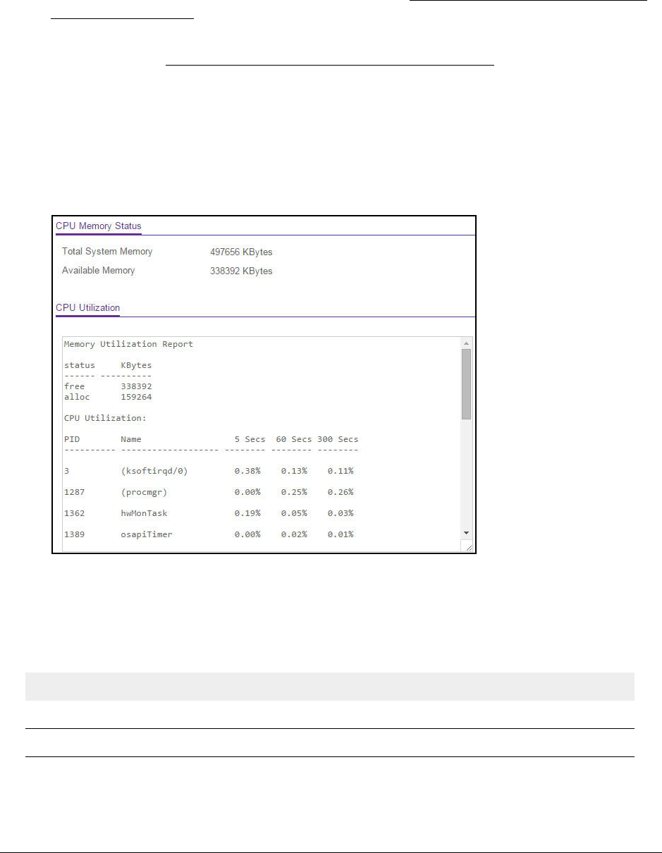
View the System CPU Status
You can monitor the CPU, memory resources, and utilization patterns across various
intervals to assess the performance, load, and stability settings of the switch.
To view the system CPU status:
1. Connect your computer to the same network as the switch.
You can use a WiFi or wired connection to connect your computer to the network, or
connect directly to a switch that is off-network using an Ethernet cable.
2. Launch a web browser.
S350 Series 8-Port Gigabit Ethernet Smart Managed Pro Switch Models GS308T and GS310TP
Configure System Information User Manual35
3. In the address field of your web browser, enter the IP address of the switch.
If you do not know the IP address of the switch, see Discover or Change the Switch IP
Address on page 12.
Your web browser might display a security message, which you can ignore. For more
information, see Access the Local Browser Interface on page 19.
The login window opens.
4. Enter the switch’s password in the Password field.
The default password is password.
The System Information page displays.
5. Select System > Management > System CPU Status > System CPU Status.
The CPU Utilization section shows the memory information, task-related information, and
percentage of CPU utilization per task.
The following table describes CPU Memory Status information.
Table 6. CPU Memory Status information
Field Description
Total System Memory The total memory of the switch in KBytes.
Available Memory The available memory space for the switch in KBytes.

S350 Series 8-Port Gigabit Ethernet Smart Managed Pro Switch Models GS308T and GS310TP
Configure System Information User Manual36
Configure the CPU Thresholds
The CPU Utilization Threshold notification feature allows you to configure thresholds that,
when exceeded, trigger a notification. The notification occurs through SNMP trap and syslog
messages.
To configure the CPU thresholds:
1. Connect your computer to the same network as the switch.
You can use a WiFi or wired connection to connect your computer to the network, or
connect directly to a switch that is off-network using an Ethernet cable.
2. Launch a web browser.
3. In the address field of your web browser, enter the IP address of the switch.
If you do not know the IP address of the switch, see Discover or Change the Switch IP
Address on page 12.
Your web browser might display a security message, which you can ignore. For more
information, see Access the Local Browser Interface on page 19.
The login window opens.
4. Enter the switch’s password in the Password field.
The default password is password.
The System Information page displays.
5. Select System > Management > System CPU Status > CPU Threshold.
6. Specify the thresholds:
• Rising Threshold. Notification is generated when the total CPU utilization exceeds
this threshold value over the configured time period. The range is 1 to 100.
• Rising Interval. This utilization monitoring time period can be configured from 5 to
86400 seconds in multiples of 5 seconds.
• Falling Threshold. Notification is triggered when the total CPU utilization falls below
this level for a configured period of time.
The falling utilization threshold must be equal to or less than the rising threshold
value. The falling utilization threshold notification is sent only if a rising threshold
notification was sent previously. Configuring the falling utilization threshold and time
period is optional. If the Falling CPU utilization settings are not configured, the switch

S350 Series 8-Port Gigabit Ethernet Smart Managed Pro Switch Models GS308T and GS310TP
Configure System Information User Manual37
uses the same values as the values that are used for the Rising CPU utilization. The
range is 1 to 100.
• Falling Interval. The utilization monitoring time period can be configured from
5 seconds to 86400 seconds in multiples of 5 seconds.
• Free Memory Threshold. The free memory threshold value for the CPU in KB.
7. Click the Apply button.
Your settings are saved.
Configure the IP Network and VLAN Settings for the
Local Browser Interface
You can configure network information for the local browser interface, which is the logical
interface used for in-band connectivity with the switch through any of the switch’s front-panel
ports. The configuration settings associated with the switch’s network interface do not affect
the configuration of the front panel ports through which traffic is switched or routed.
To configure the IP network and VLAN settings for the local browser interface:
1. Connect your computer to the same network as the switch.
You can use a WiFi or wired connection to connect your computer to the network, or
connect directly to a switch that is off-network using an Ethernet cable.
2. Launch a web browser.
3. In the address field of your web browser, enter the IP address of the switch.
If you do not know the IP address of the switch, see Discover or Change the Switch IP
Address on page 12.
Your web browser might display a security message, which you can ignore. For more
information, see Access the Local Browser Interface on page 19.
The login window opens.
4. Enter the switch’s password in the Password field.
The default password is password.
The System Information page displays.
5. Select System > Management > IP Configuration.
The IP Configuration page displays.
6. Select one of the following radio buttons to specify how the network information for the
switch must be configured:
• Static IP Address. Specifies that the IP address, subnet mask, and default gateway
must be manually configured. Enter this information in the fields below this radio
button.

S350 Series 8-Port Gigabit Ethernet Smart Managed Pro Switch Models GS308T and GS310TP
Configure System Information User Manual38
• Dynamic IP Address (BOOTP). Specifies that the switch must obtain the IP address
through a BootP server.
• Dynamic IP Address (DHCP). Specifies that the switch must obtain the IP address
through a DHCP server.
7. If you select the Static IP Address radio button, configure the following network information:
• IP Address. The IP address of the network interface. The default value is
192.168.0.239. Each part of the IP address must start with a number other than zero.
For example, IP addresses 001.100.192.6 and 192.001.10.3 are not valid.
• Subnet Mask. The IP subnet mask for the interface. The default value is
255.255.255.0.
• Default Gateway. The default gateway for the IP interface. The default value is
192.168.0.254.
8. Specify the VLAN ID for the management VLAN.
The management VLAN is used to establish an IP connection to the switch from a
workstation that is connected to a port in the same VLAN. If not specified, the active
management VLAN ID is 1 (default), which allows an IP connection to be established
through any port.
When the management VLAN is set to a different value, an IP connection can be made
only through a port that is part of the management VLAN. Also, the port VLAN ID (PVID)
of the port to be connected in that management VLAN must be the same as the
management VLAN ID.
Note: Make sure that the VLAN that must be the management VLAN exists.
Also make sure that the PVID of at least one port in the VLAN is the
same as the management VLAN ID. For information about creating
VLANs and configuring the PVID for a port, see Configure VLANs on
page 111.
The following requirements apply to the management VLAN:
•Only one management VLAN can be active at a time.
•When a new management VLAN is configured, connectivity through the existing
management VLAN is lost.
•The management station must be reconnected to the port in the new management
VLAN.
9. Click the Apply button.
Your settings are saved.

S350 Series 8-Port Gigabit Ethernet Smart Managed Pro Switch Models GS308T and GS310TP
Configure System Information User Manual39
Configure the Time Settings
The switch supports the Simple Network Time Protocol (SNTP). As its name suggests, it is a
less complicated version of Network Time Protocol, which is a system for synchronizing the
clocks of networked computer systems, primarily when data transfer is handled through the
Internet. You can also set the system time manually.
Configure the Time Setting Manually
You can view and adjust date and time settings.
To manually configure the time setting:
1. Connect your computer to the same network as the switch.
You can use a WiFi or wired connection to connect your computer to the network, or
connect directly to a switch that is off-network using an Ethernet cable.
2. Launch a web browser.
3. In the address field of your web browser, enter the IP address of the switch.
If you do not know the IP address of the switch, see Discover or Change the Switch IP
Address on page 12.
Your web browser might display a security message, which you can ignore. For more
information, see Access the Local Browser Interface on page 19.
The login window opens.
4. Enter the switch’s password in the Password field.
The default password is password.
The System Information page displays.
5. Select System > Management > Time > Time Configuration.
6. Select the Clock Source Local radio button.
7. In the Date field, specify the current date by entering the month, day, and year
(MM/DD/YYYY).
8. In the Time field, specify the current time by entering in hours, minutes, and seconds
(HH:MM:SS).

S350 Series 8-Port Gigabit Ethernet Smart Managed Pro Switch Models GS308T and GS310TP
Configure System Information User Manual40
Note: If you do not enter a date and time, the switch calculates the date and
time using the CPU’s clock cycle.
9. In the Time Zone Name field, specify the acronym for a time zone.
You can also specify the number of hours and number of minutes that the time zone is
different from the Coordinated Universal Time (UTC). The time zone can affect the
display of the current system time. The default value is UTC.
Note: When using SNTP/NTP time servers to update the switch’s clock, the
time data received from the server is based on the UTC, which is the
same as Greenwich Mean Time (GMT). This might not be the time
zone in which the switch is located.
10. In the Offset Hours field, specify the number of hours that the time zone is different from the
UTC.
For more information see the description for Time Zone Name in Step 9. The allowed
range is –12 to 13. The default value is 0.
11. In the Offset Minutes field, specify the number of minutes that the time zone is different
from UTC.
For more information see the description for Time Zone Name in Step 9. The allowed
range is 0 to 59. The default value is 0.
12. Click the Apply button.
Your settings are saved.
Configure the Time Settings With SNTP and Configure the Global SNTP
Settings
To configure the time by using SNTP and configure the global SNTP settings:
1. Connect your computer to the same network as the switch.
You can use a WiFi or wired connection to connect your computer to the network, or
connect directly to a switch that is off-network using an Ethernet cable.
2. Launch a web browser.
3. In the address field of your web browser, enter the IP address of the switch.
If you do not know the IP address of the switch, see Discover or Change the Switch IP
Address on page 12.
Your web browser might display a security message, which you can ignore. For more
information, see Access the Local Browser Interface on page 19.
The login window opens.
4. Enter the switch’s password in the Password field.
The default password is password.

S350 Series 8-Port Gigabit Ethernet Smart Managed Pro Switch Models GS308T and GS310TP
Configure System Information User Manual41
The System Information page displays.
5. Select System > Management > Time > Time Configuration.
The Time Configuration page displays.
6. Select the Clock Source SNTP radio button.
The local clock can be set to SNTP only if the following two conditions are met:
•An SNTP server is configured.
•The switch can contact the SNTP server.
7. Next to Client Mode, select the mode of operation of the SNTP client:
• Unicast. SNTP operates in a point-to-point fashion. A unicast client sends a request
to a designated server at its unicast address and expects a reply from which it can
determine the time and, optionally, the round-trip delay and local clock offset relative
to the server.
• Broadcast. SNTP operates in the same manner as multicast mode but uses a local
broadcast address instead of a multicast address. The broadcast address provides a
single-subnet scope while a multicast address provides an Internet-wide scope.
The default value is Unicast.
8. If the SNTP client mode is Unicast, use the SNTP Server Configuration page to add the IP
address or DNS name of one or more SNTP servers for the switch to poll.
For more information, see Configure an SNTP Server on page 44.
9. In the Port field, specify the local UDP port that the SNTP client receives server packets on.

S350 Series 8-Port Gigabit Ethernet Smart Managed Pro Switch Models GS308T and GS310TP
Configure System Information User Manual42
The allowed range is 1025 to 65535 and 123. The default value is 123. When the default
value is configured, the actual client port value used in SNTP packets is assigned by the
switch.
10. In the Unicast Poll Interval field, specify the number of seconds between unicast poll
requests expressed as a power of 2. The allowed range is 6 to 10. The default value is 6.
11. In the Broadcast Poll Interval field, specify the number of seconds between broadcast poll
requests expressed as a power of 2.
Broadcasts received prior to the expiry of this interval are discarded. The allowed range is
6 to 10. The default value is 6.
12. In the Unicast Poll Timeout field, specify the number of seconds to wait for an SNTP
response to a unicast poll request.
The allowed range is 1 to 30. The default value is 5.
13. In the Unicast Poll Retry field, specify the number of times to retry a unicast poll request to
an SNTP server after the first time-out before the switch attempts to use the next configured
server.
The allowed range is 0 to 10. The default value is 1.
14. In the Time Configuration section (above the SNTP Global Configuration section),
configure the following settings:
a. In the Time Zone Name field, specify the acronym for a time zone.
You can also specify the number of hours and number of minutes that the time zone
is different from the Coordinated Universal Time (UTC). The time zone can affect the
display of the current system time. The default value is UTC.
Note: When using SNTP/NTP time servers to update the switch’s clock, the
time data received from the server is based on the UTC, which is the
same as Greenwich Mean Time (GMT). This might not be the time
zone in which the switch is located.
b. In the Offset Hours field, specify the number of hours that the time zone is different
from the UTC.
For more information see the description for Time Zone Name in Step a. The allowed
range is –12 to 13. The default value is 0.
c. In the Offset Minutes field, specify the number of minutes that the time zone is
different from UTC.
For more information see the description for Time Zone Name in Step a. The allowed
range is 0 to 59. The default value is 0.
15. Click the Apply button.
Your settings are saved.

S350 Series 8-Port Gigabit Ethernet Smart Managed Pro Switch Models GS308T and GS310TP
Configure System Information User Manual43
View the SNTP Global Status
When you select the SNTP option as the clock source, you can view the SNTP global status.
To view the SNTP global status:
1. Connect your computer to the same network as the switch.
You can use a WiFi or wired connection to connect your computer to the network, or
connect directly to a switch that is off-network using an Ethernet cable.
2. Launch a web browser.
3. In the address field of your web browser, enter the IP address of the switch.
If you do not know the IP address of the switch, see Discover or Change the Switch IP
Address on page 12.
Your web browser might display a security message, which you can ignore. For more
information, see Access the Local Browser Interface on page 19.
The login window opens.
4. Enter the switch’s password in the Password field.
The default password is password.
The System Information page displays.
5. Select System > Management > Time > Time Configuration.
6. Make sure that the Clock Source SNTP radio button is selected.
The SNTP Global Status section displays below the SNTP Global Configuration section.
7. Click the Update button to update the page with the latest information about the switch.

S350 Series 8-Port Gigabit Ethernet Smart Managed Pro Switch Models GS308T and GS310TP
Configure System Information User Manual44
The following table displays the nonconfigurable SNTP Global Status information.
Table 7. SNTP Global Status information
Field Description
Version The SNTP version that the client supports.
Supported mode The SNTP modes that the client supports. Multiple modes can be supported by a client.
Last Update Time The local date and time (UTC) that the SNTP client last updated the system clock.
Last Attempt Time The local date and time (UTC) of the last SNTP request or receipt of an unsolicited
message.
Last Attempt Status The status of the last SNTP request or unsolicited message for both unicast and
broadcast modes. If no message was received from a server, a status of Other is
displayed. These values are appropriate for all operational modes.
• Other. The status of the last request is unknown.
• Success. The SNTP operation was successful and the system time was updated.
• Request Timed Out. After an SNTP request was sent to an SNTP server, the
response timer expired before a response from the server was received.
• Bad
Date Encoded. The time provided by the SNTP server is not valid.
• Version
Not Supported. The SNTP version supported by the server is not
compatible with the version supported by the client.
• Server Unsynchronized. The SNTP server is not synchronized with its peers. This
is indicated by the leap indicator field in the SNTP message.
Server IP Address The IP address of the server for the last received valid packet. If no message was
received from any server, an empty string is shown.
Address Type The address type of the SNTP server address for the last received valid packet.
Server Stratum The claimed stratum of the server for the last received valid packet.
Reference Clock ID The reference clock identifier of the server for the last received valid packet.
Server mode The mode of the server for the last received valid packet.
Unicast Server Max
Entries The maximum number of unicast server entries that can be configured on this client.
Unicast Server
Current Entries The number of current valid unicast server entries configured for this client.
Broadcast Count The number of unsolicited broadcast SNTP messages that were received and processed
by the SNTP client since the last reboot.
Configure an SNTP Server
SNTP assures accurate network device clock time synchronization up to the millisecond.
Time synchronization is performed by a network SNTP server. The switch operates only as
an SNTP client and cannot provide time services to other systems.
Time sources are established by strata. Strata define the accuracy of the reference clock.
The higher the stratum (where zero is the highest), the more accurate the clock. The device
receives time from Stratum 1 and above since it is itself a Stratum 2 device.

S350 Series 8-Port Gigabit Ethernet Smart Managed Pro Switch Models GS308T and GS310TP
Configure System Information User Manual45
The following is an example of strata:
• Stratum 0. A real-time clock is used as the time source, for example, a GPS system.
• Stratum 1. A server that is directly linked to a Stratum 0 time source is used. Stratum 1
time servers provide primary network time standards.
• Stratum 2. The time source is distanced from the Stratum 1 server over a network path.
For example, a Stratum 2 server receives the time over a network link, through NTP, from
a Stratum 1 server.
Information received from SNTP servers is evaluated based on the time level and server
type.
SNTP time definitions are assessed and determined by the following time levels:
•T1. Time that the original request was sent by the client.
•T2. Time that the original request was received by the server.
•T
3. Time that the server sent a reply.
•T
4. Time that the client received the server's reply.
The device can poll unicast server types for the server time.
Polling for unicast information is used for polling a server for which the IP address is known.
SNTP servers that were configured on the device are the only ones that are polled for
synchronization information. T1 through T4 are used to determine server time. This is the
preferred method for synchronizing device time because it is the most secure method. If this
method is selected, SNTP information is accepted only from SNTP servers defined on the
device using the SNTP Server Configuration page.
The device retrieves synchronization information, either by actively requesting information or
at every poll interval.
You can view and modify information for adding and modifying Simple Network Time
Protocol SNTP servers.
Add an SNTP Server
To add an SNTP server:
1. Connect your computer to the same network as the switch.
You can use a WiFi or wired connection to connect your computer to the network, or
connect directly to a switch that is off-network using an Ethernet cable.
2. Launch a web browser.
3. In the address field of your web browser, enter the IP address of the switch.
If you do not know the IP address of the switch, see Discover or Change the Switch IP
Address on page 12.
Your web browser might display a security message, which you can ignore. For more
information, see Access the Local Browser Interface on page 19.
The login window opens.

S350 Series 8-Port Gigabit Ethernet Smart Managed Pro Switch Models GS308T and GS310TP
Configure System Information User Manual46
4. Enter the switch’s password in the Password field.
The default password is password.
The System Information page displays.
5. Select System > Management > Time > SNTP Server Configuration.
The SNTP Server Configuration page displays.
6. From the Server Type menu, select the type of SNTP address to enter in the address field.
The address can be either an IP address (IPv4) or a host name (DNS).
7. In the Address field, specify the IP address or the host name of the SNTP server.
This is a text string of up to 64 characters, containing the encoded unicast IP address or
host name of an SNTP server. Unicast SNTP requests are sent to this address. If this
address is a DNS host name, then that host name is resolved into an IP address each
time an SNTP request is sent to it.
8. If the UDP port on the SNTP server to which SNTP requests are sent is not the standard
port (123), specify the port number in the Port field.
The range is from 1 to 65535. The default value is 123.
9. In the Priority field, specify the priority order which to query the servers.
The SNTP client on the device continues sending SNTP requests to different servers until
a successful response is received, or all servers are exhausted. The priority indicates the
order in which to query the servers. The request is sent to an SNTP server with a priority
value of 1 first, then to a server with a priority value of 2, and so on. If any servers are
assigned the same priority, the SNTP client contacts the servers in the order that they
appear in the table. The range is from 1 to 3. The default value is 1.
10. In the Version field, specify the NTP version running on the server.
The range is 1 to 4. The default value is 4.
11. Click the Add button.
The SNTP server entry is added.
12. Repeat the previous steps to add additional SNTP servers.
You can configure up to three SNTP servers.

S350 Series 8-Port Gigabit Ethernet Smart Managed Pro Switch Models GS308T and GS310TP
Configure System Information User Manual47
The SNTP Server Status table displays status information about the SNTP servers
configured on your switch. The following table describes the SNTP Server Global Status
information.
Table 8. SNTP Server Status information
Field Description
Address All the existing server addresses. If no server configuration exists, a message stating
that no SNTP server exists displays on the page.
Last Update Time The local date and time (UTC) that the response from this server was used to update
the system clock.
Last Attempt Time The local date and time (UTC) that this SNTP server was last queried.
Last Attempt Status The status of the last SNTP request or unsolicited message for both unicast and
broadcast modes. If no message was received from a server, a status of Other is
displayed. These values are appropriate for all operational modes:
• Other. The status of the last request is unknown, or no SNTP responses were
received.
• Success. The SNTP operation was successful and the system time was updated.
• Request Timed Out. After an SNTP request was sent to an SNTP server, the
response timer expired before a response from the server was received.
• Bad
Date Encoded. The time provided by the SNTP server is not valid.
• Version Not Supported. The SNTP version supported by the server is not
compatible with the version supported by the client.
• Server Unsynchronized. The SNTP server is not synchronized with its peers. This
is indicated by the leap indicator field on the SNTP message.
• Server
Kiss Of Death. The SNTP server indicated that no further queries were to
be sent to this server. This is indicated by a stratum field equal to 0 in a message
received from a server.
Requests The number of SNTP requests made to this server since last agent reboot.
Failed Requests The number of failed SNTP requests made to this server since the last reboot.
Change the Settings for an Existing SNTP Server
To change the settings for an existing SNTP server:
1. Connect your computer to the same network as the switch.
You can use a WiFi or wired connection to connect your computer to the network, or
connect directly to a switch that is off-network using an Ethernet cable.
2. Launch a web browser.
3. In the address field of your web browser, enter the IP address of the switch.
If you do not know the IP address of the switch, see Discover or Change the Switch IP
Address on page 12.
Your web browser might display a security message, which you can ignore. For more
information, see Access the Local Browser Interface on page 19.
The login window opens.

S350 Series 8-Port Gigabit Ethernet Smart Managed Pro Switch Models GS308T and GS310TP
Configure System Information User Manual48
4. Enter the switch’s password in the Password field.
The default password is password.
The System Information page displays.
5. Select System > Management > Time > SNTP Server Configuration.
The SNTP Server Configuration page displays.
6. Select the check box next to the configured server.
7. Specify new values in the available fields.
8. Click the Apply button.
Your settings are saved.
Remove an SNTP Server
To remove an SNTP server:
1. Connect your computer to the same network as the switch.
You can use a WiFi or wired connection to connect your computer to the network, or
connect directly to a switch that is off-network using an Ethernet cable.
2. Launch a web browser.
3. In the address field of your web browser, enter the IP address of the switch.
If you do not know the IP address of the switch, see Discover or Change the Switch IP
Address on page 12.
Your web browser might display a security message, which you can ignore. For more
information, see Access the Local Browser Interface on page 19.
The login window opens.
4. Enter the switch’s password in the Password field.
The default password is password.
The System Information page displays.
5. Select System > Management > Time > SNTP Server Configuration.
The SNTP Server Configuration page displays.
6. Select the check box next to the configured server to remove.
7. Click the Delete button.
The entry is removed, and the device is updated.
Configure Daylight Saving Time Settings
You can configure settings for summer time, which is also known as daylight saving time.
Used in some countries around the world, summer time is the practice of temporarily

S350 Series 8-Port Gigabit Ethernet Smart Managed Pro Switch Models GS308T and GS310TP
Configure System Information User Manual49
advancing clocks during the summer months. Typically clocks are adjusted forward one or
more hours near the start of spring and are adjusted backward in autumn.
To configure the daylight saving time settings:
1. Connect your computer to the same network as the switch.
You can use a WiFi or wired connection to connect your computer to the network, or
connect directly to a switch that is off-network using an Ethernet cable.
2. Launch a web browser.
3. In the address field of your web browser, enter the IP address of the switch.
If you do not know the IP address of the switch, see Discover or Change the Switch IP
Address on page 12.
Your web browser might display a security message, which you can ignore. For more
information, see Access the Local Browser Interface on page 19.
The login window opens.
4. Enter the switch’s password in the Password field.
The default password is password.
The System Information page displays.
5. Select System > Management > Time > DayLight Saving Configuration.
6. Select a Daylight Saving (DST) radio button:
• Disable. Disable daylight saving time.
• Recurring. Daylight saving time occurs at the same time every year. The start and
end times and dates for the time shift must be manually configured.
• Recurring EU. The system clock uses the standard recurring summer time settings
used in countries in the European Union. When this option is selected, the rest of the
applicable fields on the page are automatically populated and cannot be edited.
• Recurring USA. The system clock uses the standard recurring daylight saving time
settings used in the United States. When this option is selected, the rest of the
applicable fields on the page are automatically populated and cannot be edited.

S350 Series 8-Port Gigabit Ethernet Smart Managed Pro Switch Models GS308T and GS310TP
Configure System Information User Manual50
• Non Recurring. Daylight saving time settings are in effect only between the start date
and end date of the specified year. When this option is selected, the summer time
settings do not repeat on an annual basis.
7. Depending on your selection, configure the additional fields:
•If you select the DayLight Saving (DST) Recurring, Recurring EU, or Recurring
USA radio button, the fields in the following table are visible and you must configure
them.
Table 9. Daylight saving setting is Recurring, Recurring EU, or Recurring USA
Field Description
Begins At These fields are used to configure the start values of the date and time.
• Week. Configure the start week in the month.
• Day. Configure the start day in the week.
• Month. Configure the start month.
• Hours. Configure the start hour.
• Minutes. Configure the start minutes.
Ends At These fields are used to configure the end values of date and time.
• Week. Configure the end week in the month.
• Day. Configure the end day in the week.
• Month. Configure the end month.
• Hours. Configure the end hour.
• Minutes. Configure the end minutes.
Offset Configure recurring offset in minutes. The range is from 1 to 1440 minutes.
Zone Configure the time zone.
•If you select the DayLight Saving (DST) Non Recurring radio button, the fields in the
following table are visible and you must configure them.
Table 10. Daylight saving setting is Non Recurring
Field Description
Begins At These fields are used to configure the start values of the date and time.
• Month. Configure the start month.
• Date. Configure the start date in the month.
• Year. Configure the start year.
• Hours. Configure the start hour.
• Minutes. Configure the start minutes.
Ends At These fields are used to configure the end values of date and time.
• Month. Configure the end month.
• Date. Configure the end date in the month.
• Year. Configure the end year.
• Hours. Configure the end hour.
• Minutes. Configure the end minutes.

S350 Series 8-Port Gigabit Ethernet Smart Managed Pro Switch Models GS308T and GS310TP
Configure System Information User Manual51
8. Click the Apply button.
Your settings are saved.
View the DayLight Saving Time Status
The Daylight Saving (DST) Status section shows information about the summer time settings
and whether the time shift for summer time is currently in effect.
To view the daylight saving time status:
1. Connect your computer to the same network as the switch.
You can use a WiFi or wired connection to connect your computer to the network, or
connect directly to a switch that is off-network using an Ethernet cable.
2. Launch a web browser.
3. In the address field of your web browser, enter the IP address of the switch.
If you do not know the IP address of the switch, see Discover or Change the Switch IP
Address on page 12.
Your web browser might display a security message, which you can ignore. For more
information, see Access the Local Browser Interface on page 19.
The login window opens.
4. Enter the switch’s password in the Password field.
The default password is password.
The System Information page displays.
5. Select System > Management > Time > DayLight Saving Configuration.
Offset Specify the number of minutes to shift the summer time from the standard time.
The range is from 1 to 1440 minutes.
Zone Specify the acronym associated with the time zone when summer time is in
effect. This field is not validated against an official list of time zone acronyms.
Table 10. Daylight saving setting is Non Recurring (continued)
Field Description
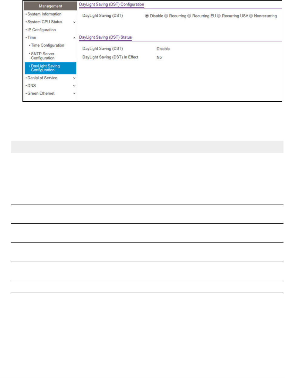
S350 Series 8-Port Gigabit Ethernet Smart Managed Pro Switch Models GS308T and GS310TP
Configure System Information User Manual52
6. To refresh the page, click the Update button.
The following table displays the nonconfigurable daylight saving status information.
Table 11. Daylight Saving (DST) Status information
Field Description
Daylight Saving (DST) The Daylight Saving value, which is one of the following:
• Disable
• Recurring
• Recurring EU
• Recurring USA
• Non Recurring
Begins At The start date of daylight saving time. This field is not displayed when
daylight saving time is disabled.
Ends At The end date of daylight saving time. This field is not displayed when
daylight saving time is disabled.
Offset (in Minutes) The offset value in minutes.This field is not displayed when daylight saving
time is disabled.
Zone The zone acronym. This field is not displayed when daylight saving time is
disabled.
Daylight Saving (DST) in Effect Indicates whether daylight saving time is in effect.

S350 Series 8-Port Gigabit Ethernet Smart Managed Pro Switch Models GS308T and GS310TP
Configure System Information User Manual53
Configure Denial of Service Settings
You can configure the Denial of Service (DoS) settings for the switch. The switch provides
support for classifying and blocking specific types of DoS attacks.
Configure Auto-DoS
You can automatically enable all the DoS features available on the switch, except for the L4
Port attack. For information about the types of DoS attacks the switch can monitor and block,
see Configure Denial of Service on page 53.
To enable the Auto-DoS feature:
1. Connect your computer to the same network as the switch.
You can use a WiFi or wired connection to connect your computer to the network, or
connect directly to a switch that is off-network using an Ethernet cable.
2. Launch a web browser.
3. In the address field of your web browser, enter the IP address of the switch.
If you do not know the IP address of the switch, see Discover or Change the Switch IP
Address on page 12.
Your web browser might display a security message, which you can ignore. For more
information, see Access the Local Browser Interface on page 19.
The login window opens.
4. Enter the switch’s password in the Password field.
The default password is password.
The System Information page displays.
5. Select System > Management > Denial of Service > Auto-DoS Configuration.
The Auto-DoS Configuration page displays.
6. Select the Auto-DoS Mode Enable radio button.
When an attack is detected, a warning message is logged to the buffered log and is sent
to the syslog server. At the same time, the port is shut down and can be enabled only
manually by the admin user.
7. Click the Apply button.
Your settings are saved.
Configure Denial of Service
You can select which types of DoS attacks the switch monitors and blocks.
To configure individual DoS settings:
1. Connect your computer to the same network as the switch.
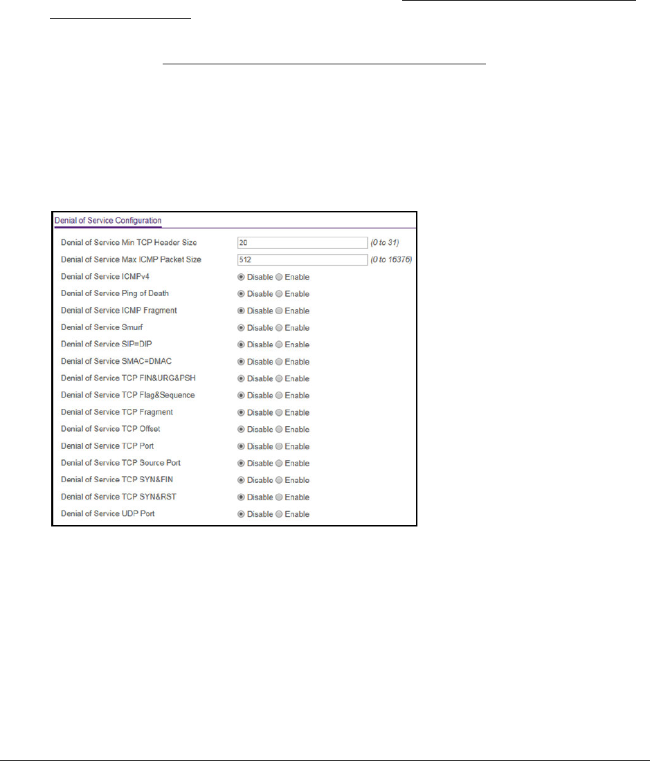
S350 Series 8-Port Gigabit Ethernet Smart Managed Pro Switch Models GS308T and GS310TP
Configure System Information User Manual54
You can use a WiFi or wired connection to connect your computer to the network, or
connect directly to a switch that is off-network using an Ethernet cable.
2. Launch a web browser.
3. In the address field of your web browser, enter the IP address of the switch.
If you do not know the IP address of the switch, see Discover or Change the Switch IP
Address on page 12.
Your web browser might display a security message, which you can ignore. For more
information, see Access the Local Browser Interface on page 19.
The login window opens.
4. Enter the switch’s password in the Password field.
The default password is password.
The System Information page displays.
5. Select System > Management > Denial of Service > Denial of Service Configuration.
6. Select the types of DoS attacks for the switch to monitor and block and configure any
associated values:
• Denial of Service Min TCP Header Size. Specify the minimum TCP header size
allowed. If DoS TCP Fragment is enabled, the switch drops packets with a TCP
header smaller than the configured value. The default value is 20.
• Denial of Service Max ICMPv4 Packet Size. Specify the maximum ICMPv4 packet
size allowed. If ICMPv4 DoS prevention is enabled, the switch drops IPv4 ICMP ping
packets with a size greater than the configured value. The default value is 512.
• Denial of Service ICMPv4. Enabling ICMPv4 DoS prevention causes the switch to
drop ICMPv4 packets with a type set to ECHO_REQ (ping) and a size greater than
the configured ICMPv4 packet size.

S350 Series 8-Port Gigabit Ethernet Smart Managed Pro Switch Models GS308T and GS310TP
Configure System Information User Manual55
• Denial of Service Ping of Death. Enabling Ping of Death DoS prevention causes the
switch to drop ICMP ping packet that are larger than 65535 bytes.
• Denial of Service ICMP Fragment. Enabling ICMP Fragment DoS prevention
causes the switch to drop ICMP fragmented packets.
• Denial of Service Smurf. Enabling Smurf DoS prevention causes the switch to drop
broadcast ICMP echo request packet.
• Denial of Service SIP=DIP. Enabling SIP=DIP DoS prevention causes the switch to
drop packets with a source IP address equal to the destination IP address.
• Denial of Service SMAC=DMAC. Enabling SMAC=DMAC DoS prevention causes
the switch to drop packets with a source MAC address equal to the destination MAC
address.
• Denial of Service TCP FIN&URG&PSH. Enabling TCP FIN & URG & PSH DoS
prevention causes the switch to drop packets with TCP flags FIN, URG, and PSH set
and the TCP sequence number equal to 0.
• Denial of Service TCP Flag&Sequence. Enabling TCP Flag DoS prevention causes
the switch to drop packets with TCP control flags set to 0 and the TCP sequence
number set to 0.
• Denial of Service TCP Fragment. Enabling TCP Fragment DoS prevention causes
the switch to drop packets with a TCP payload for which the IP payload length minus
the IP header size is less than the minimum allowed TCP header size.
• Denial of Service TCP Offset. Enabling TCP Offset DoS prevention causes the
switch to drop packets with a TCP header offset set to 1.
• Denial of Service TCP Port. Enabling TCP Port DoS prevention causes the switch to
drop packets for which the TCP source port is equal to the TCP destination port.
• Denial of Service TCP Source Port. Enabling TCP Source Port DoS prevention
causes the switch to drop packets for which the TCP source port number is lower
than 1024.
• Denial of Service TCP SYN&FIN. Enabling TCP SYN & FIN DoS prevention causes
the switch to drop packets with TCP flags SYN and FIN set.
• Denial of Service TCP SYN&RST. Enabling TCP SYN & RST DoS prevention
causes the switch to drop packets with TCP flags SYN and RST set.
• Denial of Service UDP Port. Enabling UDP Port DoS prevention causes the switch
to drop packets for which the UDP source port is equal to the UDP destination port.
7. Click the Apply button.
Your settings are saved.

S350 Series 8-Port Gigabit Ethernet Smart Managed Pro Switch Models GS308T and GS310TP
Configure System Information User Manual56
Configure DNS Settings
You can configure information about DNS servers that the network uses and how the switch
operates as a DNS client.
Configure Global DNS Settings and Add a DNS Server
You can configure global DNS settings and DNS server information.
To configure the global DNS settings and add a DNS server:
1. Connect your computer to the same network as the switch.
You can use a WiFi or wired connection to connect your computer to the network, or
connect directly to a switch that is off-network using an Ethernet cable.
2. Launch a web browser.
3. In the address field of your web browser, enter the IP address of the switch.
If you do not know the IP address of the switch, see Discover or Change the Switch IP
Address on page 12.
Your web browser might display a security message, which you can ignore. For more
information, see Access the Local Browser Interface on page 19.
The login window opens.
4. Enter the switch’s password in the Password field.
The default password is password.
The System Information page displays.
5. Select System > Management > DNS > DNS Configuration.
6. Select the Disable or Enable radio button to specify whether to disable or enable the
administrative status of the DNS client.
• Enable. Allows the switch to send DNS queries to a DNS server to resolve a DNS
domain name. The DNS is enabled by default.
•Disable. Prevents the switch from sending DNS queries.

S350 Series 8-Port Gigabit Ethernet Smart Managed Pro Switch Models GS308T and GS310TP
Configure System Information User Manual57
7. In the DNS Default Name field, enter the default DNS domain name to include in DNS
queries.
When the system is performing a lookup on an unqualified host name, this field is
provides the domain name (for example, if default domain name is netgear.com and the
user enters test, then test is changed to test.netgear.com to resolve the name). The name
must not be longer than 255 characters.
8. In the DNS Server field, specify the IPv4 address to which the switch sends DNS queries.
9. Click the Add button.
The server is added to the list. You can specify up to eight DNS servers. The Preference
field displays the server preference order. The preference is set in the order in which
preferences were entered.
10. Click the Apply button.
Your settings are saved.
The following table displays DNS Server Configuration information.
Table 12. DNS Server Configuration information
Field Description
ID The identification of the DNS Server.
Preference Shows the preference of the DNS server. The preferences are
determined by the order in which they were entered.
Remove a DNS Server
You can remove a DNS server that you no longer need.
To remove a DNS server:
1. Connect your computer to the same network as the switch.
You can use a WiFi or wired connection to connect your computer to the network, or
connect directly to a switch that is off-network using an Ethernet cable.
2. Launch a web browser.
3. In the address field of your web browser, enter the IP address of the switch.
If you do not know the IP address of the switch, see Discover or Change the Switch IP
Address on page 12.
Your web browser might display a security message, which you can ignore. For more
information, see Access the Local Browser Interface on page 19.
The login window opens.
4. Enter the switch’s password in the Password field.
The default password is password.
The System Information page displays.

S350 Series 8-Port Gigabit Ethernet Smart Managed Pro Switch Models GS308T and GS310TP
Configure System Information User Manual58
5. Select System > Management > DNS > DNS Configuration.
6. In the DNS Server Configuration table, select the check box for the DNS server.
Note: If you do not select a DNS server, all the DNS servers are removed
after you click the Delete button.
7. Click the Delete button.
The DNS server is removed.
Configure and View Host Name-to-IP Address Information
You can manually map host names to IP addresses or view dynamic host mappings.
Add a Static Entry to the Dynamic Host Mapping Table
To add a static entry to the local dynamic host mapping table:
1. Connect your computer to the same network as the switch.
You can use a WiFi or wired connection to connect your computer to the network, or
connect directly to a switch that is off-network using an Ethernet cable.
2. Launch a web browser.
3. In the address field of your web browser, enter the IP address of the switch.
If you do not know the IP address of the switch, see Discover or Change the Switch IP
Address on page 12.
Your web browser might display a security message, which you can ignore. For more
information, see Access the Local Browser Interface on page 19.
The login window opens.
4. Enter the switch’s password in the Password field.
The default password is password.
The System Information page displays.
5. Select System > Management > DNS > Host Configuration.
The DNS Host Configuration page displays.
6. In the Host Name (1 to 255 characters) field, specify the static host name to add.
Its length cannot exceed 255 characters and it is a required field.
7. In the IPv4 Address field, enter the IP address to associate with the host name.
8. Click the Add button.
Your settings are saved. The entry displays in the Dynamic Host Mapping table.

S350 Series 8-Port Gigabit Ethernet Smart Managed Pro Switch Models GS308T and GS310TP
Configure System Information User Manual59
Remove an Entry From the Dynamic Host Mapping Table
To remove an entry from the Dynamic Host Mapping table:
1. Connect your computer to the same network as the switch.
You can use a WiFi or wired connection to connect your computer to the network, or
connect directly to a switch that is off-network using an Ethernet cable.
2. Launch a web browser.
3. In the address field of your web browser, enter the IP address of the switch.
If you do not know the IP address of the switch, see Discover or Change the Switch IP
Address on page 12.
Your web browser might display a security message, which you can ignore. For more
information, see Access the Local Browser Interface on page 19.
The login window opens.
4. Enter the switch’s password in the Password field.
The default password is password.
The System Information page displays.
5. Select System > Management > DNS > Host Configuration.
The DNS Host Configuration page displays.
6. Select the check box next to the entry to remove.
7. Click the Delete button.
The entry is removed from the Dynamic Host Mapping table.
Change the Host Name or IP Address in an Entry of the Dynamic Host Mapping Table, View
All Entries, or Clear All Entries
To change the host name or IP address in an entry of the Dynamic Host Mapping table,
view all entries, or clear all entries
1. Connect your computer to the same network as the switch.
You can use a WiFi or wired connection to connect your computer to the network, or
connect directly to a switch that is off-network using an Ethernet cable.
2. Launch a web browser.
3. In the address field of your web browser, enter the IP address of the switch.
If you do not know the IP address of the switch, see Discover or Change the Switch IP
Address on page 12.
Your web browser might display a security message, which you can ignore. For more
information, see Access the Local Browser Interface on page 19.
The login window opens.

S350 Series 8-Port Gigabit Ethernet Smart Managed Pro Switch Models GS308T and GS310TP
Configure System Information User Manual60
4. Enter the switch’s password in the Password field.
The default password is password.
The System Information page displays.
5. Select System > Management > DNS > Host Configuration.
The DNS Host Configuration page display.
6. Select the check box next to the entry to update.
7. Enter the new information in the appropriate field.
8. Click the Apply button.
Your settings are saved.
9. To clear all the dynamic host name entries from the list, click the Clear button.
The Dynamic Host Mapping table shows host name-to-IP address entries that the switch
learned. The following table describes the dynamic host fields.
Table 13. Dynamic Host Mapping information
Field Description
Host Lists the host name that you assign to the specified IP address.
Total Time since the dynamic entry was first added to the table.
Elapsed Time since the dynamic entry was last updated.
Type The type of the dynamic entry.
Addresses Lists the IP address associated with the host name.
Configure Green Ethernet Settings
You can configure the green Ethernet features to reduce power consumption.
To configure the Green Ethernet settings:
1. Connect your computer to the same network as the switch.
You can use a WiFi or wired connection to connect your computer to the network, or
connect directly to a switch that is off-network using an Ethernet cable.
2. Launch a web browser.
3. In the address field of your web browser, enter the IP address of the switch.
If you do not know the IP address of the switch, see Discover or Change the Switch IP
Address on page 12.
Your web browser might display a security message, which you can ignore. For more
information, see Access the Local Browser Interface on page 19.
The login window opens.

S350 Series 8-Port Gigabit Ethernet Smart Managed Pro Switch Models GS308T and GS310TP
Configure System Information User Manual61
4. Enter the switch’s password in the Password field.
The default password is password.
The System Information page displays.
5. Select System > Management > Green Ethernet > Green Ethernet Configuration.
6. Select the Auto Power Down Mode Disable or Enable radio button.
By default, this mode is disabled. When a port link is down, the underlying physical layer
goes down for a short period and then checks for port link pulses again so that
auto-negotiation remains possible. In this way, the switch saves power when no link
partner is present for the port.
7. Select the EEE Mode Disable or Enable radio button.
By default, this mode is disabled. Energy Efficient Ethernet (EEE) combines the MAC
with a family of physical layers that support operation in a low power mode. It is defined
by the IEEE 802.3az standard. Lower power mode enables both the send and receive
sides of the link to disable some functionality for power savings when the load is light.
Transition to low power mode does not change the link status. Frames in transit are not
dropped or corrupted in transition to and from low power mode. Transition time is
transparent to upper layer protocols and applications.
8. Click the Apply button.
Your settings are saved.
Configure Green Ethernet Interface Settings
You can configure Green Ethernet settings for individual interfaces.
To configure the Green Ethernet interface settings:
1. Connect your computer to the same network as the switch.
You can use a WiFi or wired connection to connect your computer to the network, or
connect directly to a switch that is off-network using an Ethernet cable.
2. Launch a web browser.
3. In the address field of your web browser, enter the IP address of the switch.
If you do not know the IP address of the switch, see Discover or Change the Switch IP
Address on page 12.
Your web browser might display a security message, which you can ignore. For more
information, see Access the Local Browser Interface on page 19.
The login window opens.

S350 Series 8-Port Gigabit Ethernet Smart Managed Pro Switch Models GS308T and GS310TP
Configure System Information User Manual62
4. Enter the switch’s password in the Password field.
The default password is password.
The System Information page displays.
5. Select System > Management > Green Ethernet > Green Ethernet Interface
Configuration.
6. Select one or more interfaces by taking one of the following actions:
•To configure a single interface, select the check box associated with the port, or type
the port number in the Go To Interface field and click the Go button.
•To configure multiple interfaces with the same settings, select the check box
associated with each interface.
•To configure all interfaces with the same settings, select the check box in the heading
row.
7. From the Auto Power Down Mode menu, select Enable or Disable.
By default, this mode is disabled for the port. When a port link is down, the underlying
physical layer goes down for a short period and then checks for port link pulses again so
that auto-negotiation remains possible. In this way, the switch saves power when no link
partner is present for the port.
8. From the EEE mode menu, select Enable or Disable.
By default, this mode is disabled for the port. Energy Efficient Ethernet (EEE) combines
the MAC with a family of physical layers that support operation in a low power mode. It is
defined by the IEEE 802.3az standard. Lower power mode enables both the send and
receive sides of the link to disable some functionality for power savings when the load is
light. Transition to low power mode does not change the link status. Frames in transit are
not dropped or corrupted in transition to and from low power mode. Transition time is
transparent to upper layer protocols and applications.
9. Click the Apply button.
Your settings are saved.

S350 Series 8-Port Gigabit Ethernet Smart Managed Pro Switch Models GS308T and GS310TP
Configure System Information User Manual63
Use the Device View
For information about the device view, see Use the Device View of the Local Browser
Interface on page 23.
Configure PoE
On model GS310TP, you can configure the global Power over Ethernet (PoE) configuration
settings and the PoE settings for each port.
Note: For more information about PoE, see the hardware installation guide,
which you can download by visiting
netgear.com/support/download/.
Configure the Global PoE Settings
To configure the PoE settings:
1. Connect your computer to the same network as the switch.
You can use a WiFi or wired connection to connect your computer to the network, or
connect directly to a switch that is off-network using an Ethernet cable.
2. Launch a web browser.
3. In the address field of your web browser, enter the IP address of the switch.
If you do not know the IP address of the switch, see Discover or Change the Switch IP
Address on page 12.
Your web browser might display a security message, which you can ignore. For more
information, see Access the Local Browser Interface on page 19.
The login window opens.
4. Enter the switch’s password in the Password field.
The default password is password.
The System Information page displays.
5. Select System > PoE > Basic > PoE Configuration.
S350 Series 8-Port Gigabit Ethernet Smart Managed Pro Switch Models GS308T and GS310TP
Configure System Information User Manual64
The previous figure shows the PoE Configuration page for model GS310TP.
6. In the System Usage Threshold field, enter a number from 1 to 99 to set the threshold level
at which a trap is sent if the consumed power exceeds the threshold power.
7. From the Power Management Mode menu, select the power management algorithm that
the switch uses to deliver power to the requesting powered devices (PDs):
• Static. Specifies that the power allocated for each port depends on the type of power
threshold configured on the port.
• Dynamic. Specifies that the power consumption on each port is measured and
calculated in real time.
8. To active the PoE traps, from the Traps menu, select Enable.
Selecting Disable deactivates the PoE traps. The default setting is Enabled.
9. Click the Apply button.
Your settings are saved.
The following table describes the nonconfigurable fields on the page.
Table 14. PoE Configuration fields
Field Description
Firmware Version The firmware version of the PoE firmware component.
Power Status The power status.
Total Power Available Watts The maximum amount of power in watts that the switch can deliver to all ports.
Threshold Power Watts If the consumed power is below the threshold power, the switch can power up
another port. The consumed power can be between the nominal and threshold
power. The threshold power is displayed in watts.
Note: The threshold power value is determined by the value that you enter in the
System Usage Threshold field.
Consumed Power Watts The total amount of power in watts that is being delivered to all ports.
Configure the PoE Port Settings
To configure the PoE port settings:
1. Connect your computer to the same network as the switch.
You can use a WiFi or wired connection to connect your computer to the network, or
connect directly to a switch that is off-network using an Ethernet cable.
2. Launch a web browser.
3. In the address field of your web browser, enter the IP address of the switch.
If you do not know the IP address of the switch, see Discover or Change the Switch IP
Address on page 12.

S350 Series 8-Port Gigabit Ethernet Smart Managed Pro Switch Models GS308T and GS310TP
Configure System Information User Manual65
Your web browser might display a security message, which you can ignore. For more
information, see Access the Local Browser Interface on page 19.
The login window opens.
4. Enter the switch’s password in the Password field.
The default password is password.
The System Information page displays.
5. Select System > PoE > Advanced > PoE Port Configuration.
The previous figure shows the PoE Port Configuration page for model GS310TP.
6. Select the check boxes for the ports that you want to configure or select the check box in the
heading to configure all ports.
7. From the Port Power menu, select the PoE mode of the port:
• Enable. The port’s capacity to deliver power is enabled. This is the default setting.
• Disable. The port’s capacity to deliver power is disabled.
8. From the Port Priority menu, select the priority for the port in relation to other ports if the
total power that the switch is capable of delivering exceeds the total power budget:
• Low. Low priority. This is the default setting.
•Medium. Medium priority.
• High. High priority.
• Critical. Critical priority.
The port priority determines which ports can still deliver power after the total power
delivered by the switch exceeds the total power budget. (In such a situation, the switch
might not be able to deliver power to all connected devices.) If the same priority applies to
two ports, the lower-numbered port receives higher priority.
9. From the Power Mode menu, select the PoE mode that the port must function in:
• 802.3af. The port is powered in and limited to the IEEE 802.3af mode. A PD that
requires IEEE 802.3at does not receive power if the port functions in IEEE 802.3af
mode.
•Legacy. The port is powered using high-inrush current, which is used by legacy PDs
that require more than 15W to power up.
• Pre-802.3at. The port is initially powered in the IEEE 802.3af mode and, before
75 msec pass, is switched to the high power IEEE 802.3at mode. Select this mode if

S350 Series 8-Port Gigabit Ethernet Smart Managed Pro Switch Models GS308T and GS310TP
Configure System Information User Manual66
the PD does not perform Layer 2 classification or if the switch performs
2-event Layer 1 classification.
• 802.3at. The port is powered in the IEEE 802.3at mode and is backward compatible
with IEEE 802.3af. The 802.3at mode is the default mode. In this mode, if the switch
detects that the attached PD requests more power than IEEE 802.3af but is not an
IEEE 802.3at Class 4 device, the PD does not receive power from the switch.
10. From the Power Limit Type menu, select how the port controls the maximum power that it
can deliver:
• None. The port draws up to Class 0 maximum power in low power mode and up to
Class 4 maximum power in high power mode.
•Class. The port power limit is equal to the class of the attached PD.
•User. The port power limit is equal to the value that is specified in the Power Limit
(mW) field. This is the default setting.
Note: If a PD does not report its class correctly, use of these options can
preserve additional PoE power by preventing the switch from
delivering more power than the PD requires. However, depending on
which option you select, a PD that does not report its class correctly
might not power up at all.
11. In the Power Limit (mW) field, enter the maximum power (in mW) that the port can deliver.
The range is 3,000–30,000 mW. The default is 30,000 mW.
12. From the Detection Type menu, select how the port detects the attached PD:
•IEEE 802. The port performs a 4-point resistive detection. This is the default setting.
• 4pt802.3af+legacy. The port performs a 4-point resistive detection, and if required,
continues with legacy detection.
•Legacy. The port performs legacy detection.
13. From the Timer Schedule menu, select a timer schedule or select None, which is the
default selection.
For information about setting up and configuring PoE timer schedules, see Set Up PoE
Timer Schedules on page 94.
14. Click the Apply button.
Your settings are saved.
The following table describes the nonconfigurable fields on the page.
Table 15. PoE Port Configuration
Field Description
High Power All ports supports high power mode.
Power Limit (mW) The maximum power in milliwatts that can be provided by the port.

S350 Series 8-Port Gigabit Ethernet Smart Managed Pro Switch Models GS308T and GS310TP
Configure System Information User Manual67
Class The class defines the range of power that a powered device (PD) is drawing from
the switch. The class definitions are as follows:
• 0: 0.44–16.2W
• 1: 0.44–4.2W
• 2: 0.44–7.4W
• 3: 0.44–16.2W
• 4: 0.44–31.6W
• Unknown. The class cannot be detected, or no PD is attached to the port.
Output Voltage (Volts) The voltage that is delivered to the PD in volts.
Output Current (mA) The current that is delivered to the PD in mA.
Output Power (mW) The power that is delivered to the PD in milliwatts.
Status The operational status of the port:
• Disabled. No power is delivered.
• Delivering Power. Power is being drawn by the PD.
• Requesting Power. The port is requesting power.
• Fault. A problem occurred with the power.
• Searching. The port is not in one of the other states in this list.
Fault Status The error description when the PoE port is in a fault state:
• No
Error. The port is not in any error state and can provide power.
• MPS Absent. The port detected the absence of the main power supply,
preventing the port from providing power.
• Short. The port detected a short circuit condition, preventing the port from
providing power.
• Overload. The PD that is connected to the port attempts to draw more power
than allowed by the port’s settings, preventing the port from providing power at
all.
• Power Denied. The port was denied power because of a shortage of power or
because of an administrative condition. In this condition, the port cannot
provide power.
• Startup Failure. The PD that is connected to the port failed to start up. In this
condition, the port does not provide power.
• Over Voltage. The port was denied power because of a over-voltage lockout.
• Under
Voltage. The port was denied power because of an under-voltage
lockout.
• Thermal
Shutdown. The port detected a thermal temperature fault, preventing
the port from providing power.
Table 15. PoE Port Configuration (continued)
Field Description

S350 Series 8-Port Gigabit Ethernet Smart Managed Pro Switch Models GS308T and GS310TP
Configure System Information User Manual68
Configure SNMP
You can configure SNMP settings for SNMPv1/v2 and SNMPv3. The switch software
supports the configuration of SNMP groups and users that can manage traps that the SNMP
agent generates.
The switch uses both standard public MIBs for standard functionality and private MIBs that
support additional switch functionality. All private MIBs begin with a hyphen (-) prefix. The
main object for interface configuration is in -SWITCHING-MIB, which is a private MIB. Some
interface configurations also involve objects in the public MIB, IF-MIB.
Configure the SNMPv1/v2 Community
Only the communities that you define can access to the switch using the SNMP V1 and
SNMP V2 protocols. Only those communities with read/write level access can be used to
change the configuration using SNMP.
Add an SNMP Community:
To add an SNMP community:
1. Connect your computer to the same network as the switch.
You can use a WiFi or wired connection to connect your computer to the network, or
connect directly to a switch that is off-network using an Ethernet cable.
2. Launch a web browser.
3. In the address field of your web browser, enter the IP address of the switch.
If you do not know the IP address of the switch, see Discover or Change the Switch IP
Address on page 12.
Your web browser might display a security message, which you can ignore. For more
information, see Access the Local Browser Interface on page 19.
The login window opens.
4. Enter the switch’s password in the Password field.
The default password is password.
The System Information page displays.
5. Select System > SNMP > SNMP V1/V2 > Community Configuration.

S350 Series 8-Port Gigabit Ethernet Smart Managed Pro Switch Models GS308T and GS310TP
Configure System Information User Manual69
6. In the Management Station IP field, specify the IP address of the management station.
7. In the Management Station IP Mask field, specify the subnet mask to associate with the
management station IP address.
Together, the management station IP address and the management station IP mask
denote a range of IP addresses from which SNMP clients can use that community to
access this device. If either the management station IP address or management station
IP mask value is 0.0.0.0, access is allowed from any IP address. Otherwise, every client’s
address is ANDed with the mask, as is the management station IP address. If the values
are equal, access is allowed.
For example, if the management station IP address and management station IP mask
settings are 192.168.1.0/255.255.255.0, any client with an IP address in the range from
192.168.1.0 to 192.168.1.255 (inclusive) is allowed access. To allow access from only
one station, use a management station IP mask value of 255.255.255.255, and use that
computer’s IP address as the client address.
8. In the Community String field, specify a community name.
9. From the Access Mode menu, select the access level for this community, which is either
Read/Write or Read Only.
10. From the Status menu, select to enable or disable the community.
If you select Enable, the community name must be unique among all valid community
names or the set requests are rejected. If you select Disable, the community name
becomes invalid.
11. Click the Add button.
The selected community is added.
Modify an Existing SNMP Community
To modify an existing SNMP community:
1. Connect your computer to the same network as the switch.
You can use a WiFi or wired connection to connect your computer to the network, or
connect directly to a switch that is off-network using an Ethernet cable.
2. Launch a web browser.
3. In the address field of your web browser, enter the IP address of the switch.
If you do not know the IP address of the switch, see Discover or Change the Switch IP
Address on page 12.
Your web browser might display a security message, which you can ignore. For more
information, see Access the Local Browser Interface on page 19.
The login window opens.
4. Enter the switch’s password in the Password field.
The default password is password.

S350 Series 8-Port Gigabit Ethernet Smart Managed Pro Switch Models GS308T and GS310TP
Configure System Information User Manual70
The System Information page displays.
5. Select System > SNMP > SNMP V1/V2 > Community Configuration.
The Community Configuration page displays.
6. Select the check box next to the community.
7. Update the desired fields.
8. Click the Apply button.
Your settings are saved.
Delete an SNMP Community
To delete an SNMP community:
1. Connect your computer to the same network as the switch.
You can use a WiFi or wired connection to connect your computer to the network, or
connect directly to a switch that is off-network using an Ethernet cable.
2. Launch a web browser.
3. In the address field of your web browser, enter the IP address of the switch.
If you do not know the IP address of the switch, see Discover or Change the Switch IP
Address on page 12.
Your web browser might display a security message, which you can ignore. For more
information, see Access the Local Browser Interface on page 19.
The login window opens.
4. Enter the switch’s password in the Password field.
The default password is password.
The System Information page displays.
5. Select System > SNMP > SNMP V1/V2 > Community Configuration.
The Community Configuration page displays.
6. Select the check box next to the community to remove.
7. Click the Delete button.
The community is removed.
Configure SNMPv1/v2 Trap Settings
You can configure settings for each SNMPv1 or SNMPv2 management host that must
receive notifications about traps generated by the device. The SNMP management host is
also known as the SNMP trap receiver.

S350 Series 8-Port Gigabit Ethernet Smart Managed Pro Switch Models GS308T and GS310TP
Configure System Information User Manual71
Add an SNMP Trap Receiver
To add an SNMP trap receiver:
1. Connect your computer to the same network as the switch.
You can use a WiFi or wired connection to connect your computer to the network, or
connect directly to a switch that is off-network using an Ethernet cable.
2. Launch a web browser.
3. In the address field of your web browser, enter the IP address of the switch.
If you do not know the IP address of the switch, see Discover or Change the Switch IP
Address on page 12.
Your web browser might display a security message, which you can ignore. For more
information, see Access the Local Browser Interface on page 19.
The login window opens.
4. Enter the switch’s password in the Password field.
The default password is password.
The System Information page displays.
5. Select System > SNMP > SNMP V1/V2 > Trap Configuration.
The Trap Configuration page displays.
6. In the Recipients IP field, enter the IPv4 address at which the SNMP traps from the switch
must be received.
7. From the Version menu, select the trap version to be used by the SNMP trap receiver.
• SNMPv1. The switch uses SNMPv1 to send traps to the receiver. The default setting
is SNMPv1.
• SNMPv2. The switch uses SNMPv2 to send traps to the receiver.
8. In the Community String field, specify the name of the SNMP community that includes
the SNMP management host and the SNMP agent on the device.
This name can be up to 16 characters and is case-sensitive.
9. From the Status menu, select Enable to send traps to the receiver or select Disable to
prevent the switch from sending traps to the receiver.
10. Click the Add button.
The receiver configuration is added.
Modify Information About an Existing SNMP Recipient
To modify information about an existing SNMP recipient:
1. Connect your computer to the same network as the switch.
You can use a WiFi or wired connection to connect your computer to the network, or
connect directly to a switch that is off-network using an Ethernet cable.

S350 Series 8-Port Gigabit Ethernet Smart Managed Pro Switch Models GS308T and GS310TP
Configure System Information User Manual72
2. Launch a web browser.
3. In the address field of your web browser, enter the IP address of the switch.
If you do not know the IP address of the switch, see Discover or Change the Switch IP
Address on page 12.
Your web browser might display a security message, which you can ignore. For more
information, see Access the Local Browser Interface on page 19.
The login window opens.
4. Enter the switch’s password in the Password field.
The default password is password.
The System Information page displays.
5. Select System > SNMP > SNMP V1/V2 > Trap Configuration.
The Trap Configuration page displays.
6. Select the check box next to the recipient.
7. Change the fields as necessary.
8. Click the Apply button.
Your settings are saved.
Delete an SNMP Recipient
To delete an SNMP trap recipient:
1. Connect your computer to the same network as the switch.
You can use a WiFi or wired connection to connect your computer to the network, or
connect directly to a switch that is off-network using an Ethernet cable.
2. Launch a web browser.
3. In the address field of your web browser, enter the IP address of the switch.
If you do not know the IP address of the switch, see Discover or Change the Switch IP
Address on page 12.
Your web browser might display a security message, which you can ignore. For more
information, see Access the Local Browser Interface on page 19.
The login window opens.
4. Enter the switch’s password in the Password field.
The default password is password.
The System Information page displays.
5. Select System > SNMP > SNMP V1/V2 > Trap Configuration.
The Trap Configuration page displays.

S350 Series 8-Port Gigabit Ethernet Smart Managed Pro Switch Models GS308T and GS310TP
Configure System Information User Manual73
6. Select the check box next to the recipient to remove.
7. Click the Delete button.
The trap recipient is removed.
Configure SNMPv1/v2 Trap Flags
You can enable or disable traps that the switch can send to an SNMP manager. When the
condition identified by an active trap is encountered by the switch, a trap message is sent to
any enabled SNMP trap receivers, and a message is written to the trap log.
To configure the trap flags:
1. Connect your computer to the same network as the switch.
You can use a WiFi or wired connection to connect your computer to the network, or
connect directly to a switch that is off-network using an Ethernet cable.
2. Launch a web browser.
3. In the address field of your web browser, enter the IP address of the switch.
If you do not know the IP address of the switch, see Discover or Change the Switch IP
Address on page 12.
Your web browser might display a security message, which you can ignore. For more
information, see Access the Local Browser Interface on page 19.
The login window opens.
4. Enter the switch’s password in the Password field.
The default password is password.
The System Information page displays.
5. Select System > SNMP > SNMP V1/V2 > Trap Flags.
The Trap Flags page displays.
6. Enable or disable the following system traps:
• Authentication. When enabled, SNMP traps are sent when events involving
authentication occur, such as when a user attempts to access the switch local
browser interface and does not provide a valid user name and password. The default
is Enable.
• Link Up/Down. When enabled, SNMP traps are sent when the administrative or
operational state of a physical or logical link changes. The default is Enable.
•Spanning Tree. When enabled, SNMP traps are sent when various spanning tree
events occur. The default is Enable.
7. Click the Apply button.
Your settings are saved.

S350 Series 8-Port Gigabit Ethernet Smart Managed Pro Switch Models GS308T and GS310TP
Configure System Information User Manual74
View the Supported MIBs
You can view a list of all MIBs that are supported on the switch.
To view the supported MIBs:
1. Connect your computer to the same network as the switch.
You can use a WiFi or wired connection to connect your computer to the network, or
connect directly to a switch that is off-network using an Ethernet cable.
2. Launch a web browser.
3. In the address field of your web browser, enter the IP address of the switch.
If you do not know the IP address of the switch, see Discover or Change the Switch IP
Address on page 12.
Your web browser might display a security message, which you can ignore. For more
information, see Access the Local Browser Interface on page 19.
The login window opens.
4. Enter the switch’s password in the Password field.
The default password is password.
The System Information page displays.
5. Select System > SNMP > SNMP V1/V2 > Supported MIBs.
The following table describes the SNMP Supported MIBs Status fields.
Table 16. SNMP supported MIBs
Field Description
Name The RFC number if applicable and the name of the MIB.
Description The RFC title or MIB description.

S350 Series 8-Port Gigabit Ethernet Smart Managed Pro Switch Models GS308T and GS310TP
Configure System Information User Manual75
Configure SNMP V3 Users
Any user can connect to the switch using the SNMPv3 protocol, but for authentication and
encryption, the switch supports only one user (admin). Therefore, you can create or modify
only one profile.
To configure authentication and encryption settings for the SNMPv3 admin profile by
using the web interface:
1. Connect your computer to the same network as the switch.
You can use a WiFi or wired connection to connect your computer to the network, or
connect directly to a switch that is off-network using an Ethernet cable.
2. Launch a web browser.
3. In the address field of your web browser, enter the IP address of the switch.
If you do not know the IP address of the switch, see Discover or Change the Switch IP
Address on page 12.
Your web browser might display a security message, which you can ignore. For more
information, see Access the Local Browser Interface on page 19.
The login window opens.
4. Enter the switch’s password in the Password field.
The default password is password.
The System Information page displays.
5. Select System > SNMP > SNMPv3 > User Configuration.
The User Configuration page displays.
The SNMPv3 Access Mode field is a read-only field that shows the access privileges for
the user account. Access for the admin account is always Read/Write. Access for all
other accounts is Read Only.
6. To enable authentication, select an Authentication Protocol radio button.
You can select the MD5 radio button or the SHA radio button. With either of these
options, the user login password is used as SNMPv3 authentication password. For
information about how to configure the login password, see Change the Password for the
Local Browser Interface on page 200.
7. To enable encryption:
a. Select the Encryption Protocol DES radio button to encrypt SNMPv3 packets using
the DES encryption protocol.
b. In the Encryption Key field, enter an encryption code of eight or more alphanumeric
characters.
8. Click the Apply button.
Your settings are saved.

S350 Series 8-Port Gigabit Ethernet Smart Managed Pro Switch Models GS308T and GS310TP
Configure System Information User Manual76
Configure LLDP
The IEEE 802.1AB-defined standard, Link Layer Discovery Protocol (LLDP), allows stations
on an 802 LAN to advertise major capabilities and physical descriptions. A network manager
can view this information to identify system topology and detect bad configurations on the
LAN.
The following sections describe how you can configure LLDP:
•Configure LLDP Global Settings on page 76
•Configure LLDP Port Settings on page 78
•View the LLDP-MED Network Policy on page 79
•Configure LLDP-MED Port Settings on page 81
•View the Local Information Advertised Through LLDP on page 82
•View LLDP Neighbors Information on page 84
LLDP is a one-way protocol without any request/response sequences. Information is
advertised by stations implementing the transmit function, and is received and processed by
stations implementing the receive function. The transmit and receive functions can be
enabled or disabled separately per port. By default, both transmit and receive are disabled on
all ports. The application is responsible for starting each transmit and receive state machine
appropriately, based on the configured status and operational state of the port.
The Link Layer Discovery Protocol-Media Endpoint Discovery (LLDP-MED) is an
enhancement to LLDP with the following features:
•Autodiscovery of LAN policies (such as VLAN, Layer 2 priority, and DiffServ settings),
enabling plug and play networking.
•Device location discovery for creation of location databases.
•Extended and automated power management of Power over Ethernet endpoints.
•Inventory management, enabling network administrators to track their network devices
and determine their characteristics (manufacturer, software and hardware versions,
serial/asset number).
Configure LLDP Global Settings
You can specify the global LLDP and LLDP-MED settings that are applied to the switch.
To configure global LLDP settings:
1. Connect your computer to the same network as the switch.
You can use a WiFi or wired connection to connect your computer to the network, or
connect directly to a switch that is off-network using an Ethernet cable.
2. Launch a web browser.

S350 Series 8-Port Gigabit Ethernet Smart Managed Pro Switch Models GS308T and GS310TP
Configure System Information User Manual77
3. In the address field of your web browser, enter the IP address of the switch.
If you do not know the IP address of the switch, see Discover or Change the Switch IP
Address on page 12.
Your web browser might display a security message, which you can ignore. For more
information, see Access the Local Browser Interface on page 19.
The login window opens.
4. Enter the switch’s password in the Password field.
The default password is password.
The System Information page displays.
5. Select System > LLDP > Basic > LLDP Configuration.
6. To configure nondefault values for the following LLDP properties, specify the following
options:
• TLV Advertised Interval. The number of seconds between transmissions of LLDP
advertisements.
• Hold Multiplier. The transmit interval multiplier value, where transmit hold multiplier ×
transmit interval = the time to live (TTL) value that the device advertises to neighbors.
• Re-initializing Delay. The number of seconds to wait before attempting to re-initialize
LLDP on a port after the LLDP operating mode on the port changes.
• Transmit Delay. The minimum number of seconds to wait between transmissions of
remote data change notifications to one or more SNMP trap receivers configured on
the switch.
7. To configure a nondefault value for LLDP-MED, enter a value in the Fast Start Duration
field.
This value sets the number of LLDP packets sent when the LLDP-MED fast start
mechanism is initialized, which occurs when a new endpoint device links with the
LLDP-MED network connectivity device.
8. Click the Apply button.
Your settings are saved.

S350 Series 8-Port Gigabit Ethernet Smart Managed Pro Switch Models GS308T and GS310TP
Configure System Information User Manual78
Configure LLDP Port Settings
You can specify per-interface LLDP settings.
To configure the LLDP interface:
1. Connect your computer to the same network as the switch.
You can use a WiFi or wired connection to connect your computer to the network, or
connect directly to a switch that is off-network using an Ethernet cable.
2. Launch a web browser.
3. In the address field of your web browser, enter the IP address of the switch.
If you do not know the IP address of the switch, see Discover or Change the Switch IP
Address on page 12.
Your web browser might display a security message, which you can ignore. For more
information, see Access the Local Browser Interface on page 19.
The login window opens.
4. Enter the switch’s password in the Password field.
The default password is password.
The System Information page displays.
5. Select System > LLDP > Advanced > LLDP Port Settings.
6. Select one or more interfaces by taking one of the following actions:
•To configure a single interface, select the check box associated with the port, or type
the port number in the Go To Interface field and click the Go button.
•To configure multiple interfaces with the same settings, select the check box
associated with each interface.
•To configure all interfaces with the same settings, select the check box in the heading
row.

S350 Series 8-Port Gigabit Ethernet Smart Managed Pro Switch Models GS308T and GS310TP
Configure System Information User Manual79
7. Use the following menus to configure the LLDP settings for the selected ports:
• Admin Status. Select the status for transmitting and receiving LLDP packets:
- Tx Only. Enable only transmitting LLDP PDUs on the selected ports.
- Rx Only. Enable only receiving LLDP PDUs on the selected ports.
- Tx and Rx. Enable both transmitting and receiving LLDP PDUs on the selected
ports.
- Disabled. Do not transmit or receive LLDP PDUs on the selected ports.
The default is Tx and Rx.
• Management IP Address. Choose whether to advertise the management IP address
from the interface. The possible field values are as follows:
-Stop Advertise. Do not advertise the management IP address from the interface.
- Auto Advertise. Advertise the current IP address of the device as the
management IP address.
The default is Auto Advertise.
•Notification. When notifications are enabled, LLDP interacts with the trap manager to
notify subscribers of remote data change statistics. The default is Disable.
•Optional TLVs. Enable or disable the transmission of optional type-length value (TLV)
information from the interface. The default is Enable. The TLV information includes
the system name, system description, system capabilities, and port description.
For information about how to configure the system name, see View and Configure
the Switch Management Settings on page 32. For information about how to
configure the port description, see Configure the Port Settings and Maximum Frame
Size on page 103.
8. Click the Apply button.
Your settings are saved.
View the LLDP-MED Network Policy
You can display information about the LLPD-MED network policy TLV transmitted in the
LLDP frames on the selected local interface.
To view LLDP-MED network policy information for an interface:
1. Connect your computer to the same network as the switch.
You can use a WiFi or wired connection to connect your computer to the network, or
connect directly to a switch that is off-network using an Ethernet cable.
2. Launch a web browser.
3. In the address field of your web browser, enter the IP address of the switch.
If you do not know the IP address of the switch, see Discover or Change the Switch IP
Address on page 12.

S350 Series 8-Port Gigabit Ethernet Smart Managed Pro Switch Models GS308T and GS310TP
Configure System Information User Manual80
Your web browser might display a security message, which you can ignore. For more
information, see Access the Local Browser Interface on page 19.
The login window opens.
4. Enter the switch’s password in the Password field.
The default password is password.
The System Information page displays.
5. Select System > LLDP > Advanced > LLDP-MED Network Policy.
The LLDP-MED Network Policy page displays.
6. From the Interface menu, select the interface for which you want to view the information.
Note: The menu includes only the interfaces on which LLDP is enabled. If no
interfaces are enabled for LLDP, the Interface menu does not display.
The page refreshes and displays the data transmitted in the network policy TLVs for the
interface.
The following table describes the LLDP-MED network policy information that displays on the
page.
Table 17. LLDP-MED network policy information
Field Description
Network Policy Number The policy number.
Application The media application type associated with the policy, which can be one of the
following:
• Unknown
• Voice
• Guest Voice
• Guest Voice Signaling
• Softphone Voice
• Video Conferencing
• Streaming Video
• Video Signaling
A port can receive multiple application types. The application information is
displayed only if a network policy TLV was transmitted from the port.
VLAN ID The VLAN ID associated with the policy.
VLAN Type Indicates whether the VLAN associated with the policy is tagged or untagged.
User Priority The priority associated with the policy.
DSCP The DSCP associated with a particular policy type.

S350 Series 8-Port Gigabit Ethernet Smart Managed Pro Switch Models GS308T and GS310TP
Configure System Information User Manual81
Configure LLDP-MED Port Settings
You can enable LLDP-MED mode on an interface and configure its properties.
To configure LLDP-MED settings for a port:
1. Connect your computer to the same network as the switch.
You can use a WiFi or wired connection to connect your computer to the network, or
connect directly to a switch that is off-network using an Ethernet cable.
2. Launch a web browser.
3. In the address field of your web browser, enter the IP address of the switch.
If you do not know the IP address of the switch, see Discover or Change the Switch IP
Address on page 12.
Your web browser might display a security message, which you can ignore. For more
information, see Access the Local Browser Interface on page 19.
The login window opens.
4. Enter the switch’s password in the Password field.
The default password is password.
The System Information page displays.
5. Select System > LLDP > Advanced > LLDP-MED Port Settings.
The LLDP-MED Port Settings page displays.
6. From the Port menu, select the port to configure.
7. Use the following menus to enable or disable the following LLDP-MED settings for the
selected port:
• LLDP-MED Status. The administrative status of LLDP-MED on the interface. When
LLDP-MED is enabled, the transmit and receive function of LLDP is effectively
enabled on the interface.
• Notification. When Notification is enabled, the port sends a topology change
notification if a device is connected or removed.
• MED Capabilities. When MED Capabilities is enabled, the port transmits the
capabilities type length values (TLVs) in the LLDP PDU frames.
•Network Policy. When Network Policy is enabled, the port transmits the network
policy TLV in LLDP frames.
• Extended MDI-PSE. When Extended MDI-PSE is enabled, the port transmits the
extended PSE TLV in LLDP frames.
8. Click the Apply button.
Your settings are saved.
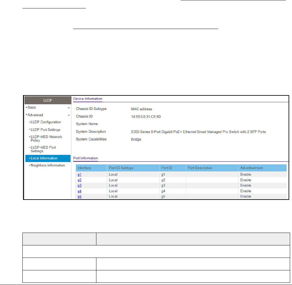
S350 Series 8-Port Gigabit Ethernet Smart Managed Pro Switch Models GS308T and GS310TP
Configure System Information User Manual82
View the Local Information Advertised Through LLDP
You can view the data that each port advertises through LLDP.
To view local LLDP information:
1. Connect your computer to the same network as the switch.
You can use a WiFi or wired connection to connect your computer to the network, or
connect directly to a switch that is off-network using an Ethernet cable.
2. Launch a web browser.
3. In the address field of your web browser, enter the IP address of the switch.
If you do not know the IP address of the switch, see Discover or Change the Switch IP
Address on page 12.
Your web browser might display a security message, which you can ignore. For more
information, see Access the Local Browser Interface on page 19.
The login window opens.
4. Enter the switch’s password in the Password field.
The default password is password.
The System Information page displays.
5. Select System > LLDP > Advanced > Local Information.
The page includes only the interfaces on which LLDP is enabled.
The following table describes the LLDP device information and port summary information.
Field Description
Device Information
Chassis ID Subtype The type of information used to identify the switch in the Chassis ID field.
Chassis ID The hardware platform identifier for the switch.
S350 Series 8-Port Gigabit Ethernet Smart Managed Pro Switch Models GS308T and GS310TP
Configure System Information User Manual83
6. To view additional details about a port, click the name of the port in the Interface column of
the Port Information table.
The following table describes the detailed local information that displays for the selected
port.
System Name The user-configured system name for the switch.
System Description The switch description, which includes information about the product model
and platform.
System Capabilities The primary functions that the switch supports.
Port Information
Interface The interface associated with the rest of the data in the row.
Port ID Subtype The type of information used to identify the interface in the Port ID field.
Port ID The port number.
Port Description The user-defined description of the port. For information about how to
configure the port description, see Configure the Port Settings and
Maximum Frame Size on page 103.
Advertisement The TLV advertisement status of the port.
Field Description
Managed Address
Address SubType The type of address the management interface uses, such as an IPv4
address.
Address The address used to manage the device.
Interface SubType The port subtype.
Interface Number The number that identifies the port.
MAC/PHY Details
Auto Negotiation Supported Indicates whether the interface supports port speed autonegotiation. The
option is True (enabled) or False (disabled).
Auto Negotiation Enabled The port speed autonegotiation support status. The option is True (enabled)
or False (disabled).
Auto Negotiation Advertised
Capabilities The port speed autonegotiation capabilities such as 1000BASE-T half-duplex
mode or 100BASE-TX full-duplex mode.
Operational MAU Type The Medium Attachment Unit (MAU) type. The MAU performs physical layer
functions, including digital data conversion from the Ethernet interface
collision detection and bit injection into the network.
Field Description
S350 Series 8-Port Gigabit Ethernet Smart Managed Pro Switch Models GS308T and GS310TP
Configure System Information User Manual84
View LLDP Neighbors Information
You can view the data that a specified interface received from other LLDP-enabled systems.
To view LLDP information received from a neighbor device:
1. Connect your computer to the same network as the switch.
You can use a WiFi or wired connection to connect your computer to the network, or
connect directly to a switch that is off-network using an Ethernet cable.
2. Launch a web browser.
3. In the address field of your web browser, enter the IP address of the switch.
If you do not know the IP address of the switch, see Discover or Change the Switch IP
Address on page 12.
Your web browser might display a security message, which you can ignore. For more
information, see Access the Local Browser Interface on page 19.
The login window opens.
4. Enter the switch’s password in the Password field.
The default password is password.
The System Information page displays.
5. Select System > LLDP > Advanced > Neighbors Information.
The Neighbors Information page displays.
If no information was received from a neighbor device, or if the link partner is not
LLDP-enabled, no information displays.
MED Details
Capabilities Supported The MED capabilities enabled on the port.
Current Capabilities The TLVs advertised by the port.
Device Class Network Connectivity indicates that the device is a network connectivity
device.
Network Policies
Application Type The media application type associated with the policy.
VLAN ID The VLAN ID associated with the policy.
VLAN Type Specifies whether the VLAN associated with the policy is tagged or untagged.
User Priority The priority associated with the policy.
DSCP The DSCP associated with a particular policy type.
Field Description

S350 Series 8-Port Gigabit Ethernet Smart Managed Pro Switch Models GS308T and GS310TP
Configure System Information User Manual85
The following table describes the information that displays for all LLDP neighbors that
were discovered.
Field Description
MSAP Entry The Media Service Access Point (MSAP) entry number for the remote
device.
Local Port The interface on the local system that received LLDP information from a
remote system.
Chassis ID Subtype The type of data displayed in the Chassis ID field on the remote system.
Chassis ID The remote 802 LAN device’s chassis.
Port ID Subtype The type of data displayed in the remote system’s Port ID field.
Port ID The physical address of the port on the remote system from which the data
was sent.
System Name The system name associated with the remote device. If the field is blank, the
name might not be configured on the remote system.
6. To view additional information about the remote device, click the link in the MSAP Entry
column.
A pop-up window displays information for the selected port.
The following table describes the information transmitted by the neighbor.
Field Description
Port Details
Local Port The interface on the local system that received LLDP information from a
remote system.
MSAP Entry The Media Service Access Point (MSAP) entry number for the remote device.
Basic Details
Chassis ID Subtype The type of data displayed in the Chassis ID field on the remote system.
Chassis ID The remote 802 LAN device’s chassis.
Port ID Subtype The type of data displayed in the remote system’s Port ID field.
Port ID The physical address of the port on the remote system from which the data
was sent.
Port Description The user-defined description of the port.
System Name The system name associated with the remote device.
System Description The description of the selected port associated with the remote system.
System Capabilities The system capabilities of the remote system.

S350 Series 8-Port Gigabit Ethernet Smart Managed Pro Switch Models GS308T and GS310TP
Configure System Information User Manual86
Managed Addresses
Address SubType The type of the management address.
Address The advertised management address of the remote system.
Interface SubType The port subtype.
Interface Number The port on the remote device that sent the information.
MAC/PHY Details
Auto-Negotiation Supported Specifies whether the remote device supports port-speed autonegotiation.
The option is True (enabled) or False (disabled).
Auto-Negotiation Enabled The port speed autonegotiation support status. The option is True (enabled)
or False (disabled).
Auto Negotiation Advertised
Capabilities The port speed autonegotiation capabilities.
Operational MAU Type The Medium Attachment Unit (MAU) type. The MAU performs physical layer
functions, including digital data conversion from the Ethernet interface
collision detection and bit injection into the network.
MED Details
Capabilities Supported The supported capabilities that were received in MED TLV from the device.
Current Capabilities The advertised capabilities that were received in MED TLV from the device.
Device Class The LLDP-MED endpoint device class. The possible device classes are as
follows:
• Endpoint Class 1 Indicates a generic endpoint class, offering basic LLDP
services.
• Endpoint Class 2 Indicates a media endpoint class, offering media
streaming capabilities as well as all Class 1 features.
• Endpoint Class 3 Indicates a communications device class, offering all
Class 1 and Class 2 features plus location, 911, Layer 2 switch support,
and device information management capabilities.
PoE Device Type The port PoE type. For example, Powered.
PoE Power Source The port’s power source.
PoE Power Priority The port’s power priority.
PoE Power Value The port’s power value.
Hardware Revision The hardware version advertised by the remote device.
Firmware Revision The firmware version advertised by the remote device.
Software Revision The software version advertised by the remote device.
Serial Number The serial number advertised by the remote device.
Field Description

S350 Series 8-Port Gigabit Ethernet Smart Managed Pro Switch Models GS308T and GS310TP
Configure System Information User Manual87
Configure DHCP Snooping
DHCP snooping is a useful feature that provides security by filtering untrusted DHCP
messages and by building and maintaining a DHCP snooping binding table. An untrusted
message is a message that is received from outside the network or firewall and that can
cause traffic attacks within your network. The DHCP snooping binding table contains the
MAC address, IP address, lease time, binding type, VLAN number, and interface information
that corresponds to the local untrusted interfaces of a switch. An untrusted interface is an
interface that is configured to receive messages from outside the network or firewall. A
trusted interface is an interface that is configured to receive only messages from within the
network.
Model Name The model name advertised by the remote device.
Asset ID The asset ID advertised by the remote device.
Location Information
Civic The physical location, such as the street address, that the remote device
advertised in the location TLV, for example, 123 45th St. E. The field value
length range is 6–160 characters.
Coordinates The location map coordinates that the remote device advertised in the
location TLV, including latitude, longitude, and altitude.
ECS ELIN The Emergency Call Service (ECS) Emergency Location Identification
Number (ELIN) that the remote device advertised in the location TLV. The
field range is 10–25.
Unknown The unknown location information for the remote device.
Network Policies
Application Type The media application type associated with the policy advertised by the
remote device.
VLAN ID The VLAN ID associated with the policy.
VLAN Type Specifies whether the VLAN associated with the policy is tagged or untagged.
User Priority The priority associated with the policy.
DSCP The DSCP associated with a particular policy type.
LLDP Unknown TLVs
Type The unknown TLV type field.
Value The unknown TLV value field.
Field Description

S350 Series 8-Port Gigabit Ethernet Smart Managed Pro Switch Models GS308T and GS310TP
Configure System Information User Manual88
DHCP snooping acts like a firewall between untrusted hosts and DHCP servers. It also
provides way to differentiate between untrusted interfaces connected to the end user and
trusted interfaces connected to the DHCP server or another switch.
Configure the Global DHCP Snooping Settings
You can view and configure the global settings for DHCP snooping.
To configure the global DHCP snooping settings:
1. Connect your computer to the same network as the switch.
You can use a WiFi or wired connection to connect your computer to the network, or
connect directly to a switch that is off-network using an Ethernet cable.
2. Launch a web browser.
3. In the address field of your web browser, enter the IP address of the switch.
If you do not know the IP address of the switch, see Discover or Change the Switch IP
Address on page 12.
Your web browser might display a security message, which you can ignore. For more
information, see Access the Local Browser Interface on page 19.
The login window opens.
4. Enter the switch’s password in the Password field.
The default password is password.
The System Information page displays.
5. Select System> Services > DHCP Snooping > Global Configuration.
6. Select the DHCP Snooping Mode Enable radio button.
The default is Disable.
7. To enable the verification of the sender’s MAC address for DHCP snooping, leave the MAC
Address Validation Enable radio button selected.
The default is Enable.

S350 Series 8-Port Gigabit Ethernet Smart Managed Pro Switch Models GS308T and GS310TP
Configure System Information User Manual89
When MAC address validation is enabled, the device checks packets that are received
on an untrusted interface to verify that the MAC address and the DHCP client hardware
address match. If the addresses do not match, the device drops the packet.
8. Click the Apply button.
Your settings are saved.
Enable DHCP for All Interfaces in a VLAN
To enable DHCP snooping for all interfaces that are members of a VLAN:
1. Connect your computer to the same network as the switch.
You can use a WiFi or wired connection to connect your computer to the network, or
connect directly to a switch that is off-network using an Ethernet cable.
2. Launch a web browser.
3. In the address field of your web browser, enter the IP address of the switch.
If you do not know the IP address of the switch, see Discover or Change the Switch IP
Address on page 12.
Your web browser might display a security message, which you can ignore. For more
information, see Access the Local Browser Interface on page 19.
The login window opens.
4. Enter the switch’s password in the Password field.
The default password is password.
The System Information page displays.
5. Select System> Services > DHCP Snooping > Global Configuration.
The DHCP Snooping Global Configuration page displays.
6. In the VLAN ID field, specify the VLAN on which DHCP snooping is enabled.
7. From the DHCP Snooping Mode menu, select Enable.
8. Click the Apply button.
Your settings are saved.
Configure DHCP Snooping Interface Settings
You can view and configure each port as a trusted or untrusted port. Any DHCP responses
received on a trusted port are forwarded. If a port is configured as untrusted, any DHCP (or
BootP) responses received on that port are discarded.
To configure DHCP snooping interface settings:
1. Connect your computer to the same network as the switch.

S350 Series 8-Port Gigabit Ethernet Smart Managed Pro Switch Models GS308T and GS310TP
Configure System Information User Manual90
You can use a WiFi or wired connection to connect your computer to the network, or
connect directly to a switch that is off-network using an Ethernet cable.
2. Launch a web browser.
3. In the address field of your web browser, enter the IP address of the switch.
If you do not know the IP address of the switch, see Discover or Change the Switch IP
Address on page 12.
Your web browser might display a security message, which you can ignore. For more
information, see Access the Local Browser Interface on page 19.
The login window opens.
4. Enter the switch’s password in the Password field.
The default password is password.
The System Information page displays.
5. Select System> Services > DHCP Snooping > Interface Configuration.
6. Select one or more interfaces by taking one of the following actions:
•To configure a single interface, select the check box associated with the port, or type
the port number in the Go To Interface field and click the Go button.
•To configure multiple interfaces with the same settings, select the check box
associated with each interface.
•To configure all interfaces with the same settings, select the check box in the heading
row.
7. From the Trust Mode menu, select the desired trust mode:
•Disabled. The interface is considered to be untrusted and could potentially be used to
launch a network attack. DHCP server messages are checked against the bindings
database. On untrusted ports, DHCP snooping enforces the following security rules:
-DHCP packets from a DHCP server (DHCPOFFER, DHCPACK, DHCPNAK,
DHCPRELEASEQUERY) are dropped.
-DHCPRELEASE and DHCPDECLINE messages are dropped if the MAC address
is in the snooping database but the binding’s interface is other than the interface
where the message was received.
-DHCP packets are dropped when the source MAC address does not match the
client hardware address if MAC address validation is globally enabled.

S350 Series 8-Port Gigabit Ethernet Smart Managed Pro Switch Models GS308T and GS310TP
Configure System Information User Manual91
• Enabled. The interface is considered to be trusted and forwards DHCP server
messages without validation.
8. From the Invalid Packets menu, select the packet logging mode.
When enabled, the DHCP snooping feature generates a log message when an invalid
packet is received and dropped by the interface.
9. In the Rate Limit (pps) field, specify the rate limit value for DHCP snooping purposes.
If the incoming rate of DHCP packets per second exceeds the configured burst interval
per second, the port shuts down. If the rate limit value is None, he burst interval is also
nonapplicable, and rate limiting is disabled.
10. In the Burst Interval (secs) field, specify the burst interval value for rate limiting purposes
on the interface.
If the rate limit is N/A, then the burst interval is also nonapplicable, and the field displays
N/A.
11. Click the Apply button.
Your settings are saved.
Configure Static DHCP Bindings
You can view, add, and remove static bindings in the DHCP snooping bindings database and
to view or clear the dynamic bindings in the bindings table.
To configure static DHCP bindings:
1. Connect your computer to the same network as the switch.
You can use a WiFi or wired connection to connect your computer to the network, or
connect directly to a switch that is off-network using an Ethernet cable.
2. Launch a web browser.
3. In the address field of your web browser, enter the IP address of the switch.
If you do not know the IP address of the switch, see Discover or Change the Switch IP
Address on page 12.
Your web browser might display a security message, which you can ignore. For more
information, see Access the Local Browser Interface on page 19.
The login window opens.
4. Enter the switch’s password in the Password field.
The default password is password.
The System Information page displays.
5. Select System> Services > DHCP Snooping > Binding Configuration.

S350 Series 8-Port Gigabit Ethernet Smart Managed Pro Switch Models GS308T and GS310TP
Configure System Information User Manual93
3. In the address field of your web browser, enter the IP address of the switch.
If you do not know the IP address of the switch, see Discover or Change the Switch IP
Address on page 12.
Your web browser might display a security message, which you can ignore. For more
information, see Access the Local Browser Interface on page 19.
The login window opens.
4. Enter the switch’s password in the Password field.
The default password is password.
The System Information page displays.
5. Select System> Services > DHCP Snooping > Persistent Configuration.
The Persistent Configuration page displays.
6. Specify where the DHCP snooping bindings database is located.
• Local. The binding table is stored locally on the switch.
•Remote. The binding table is stored on a remote TFTP server.
If the database is stored on a remote server, specify the following information:
- Remote IP Address. Specify the IP address of the TFTP server.
- Remote File Name. Specify the file name of the DHCP snooping bindings
database in which the bindings are stored.
7. In the Write Delay field, specify the time that the switch must wait after writing binding
information to persistent storage.
The delay allows the switch to collect as many entries as possible (new and removed)
before writing them to the persistent file. You can specify from 15 to 86400 seconds. By
default, the delay is 300 seconds.
8. Click the Apply button.
Your settings are saved.
View or Clear DHCP Snooping Statistics
You can view and clear per-interface statistics about the DHCP messages filtered by the
DHCP snooping feature on untrusted interfaces.
To view or clear the DHCP snooping statistics:
1. Connect your computer to the same network as the switch.
You can use a WiFi or wired connection to connect your computer to the network, or
connect directly to a switch that is off-network using an Ethernet cable.
2. Launch a web browser.
3. In the address field of your web browser, enter the IP address of the switch.

S350 Series 8-Port Gigabit Ethernet Smart Managed Pro Switch Models GS308T and GS310TP
Configure System Information User Manual94
If you do not know the IP address of the switch, see Discover or Change the Switch IP
Address on page 12.
Your web browser might display a security message, which you can ignore. For more
information, see Access the Local Browser Interface on page 19.
The login window opens.
4. Enter the switch’s password in the Password field.
The default password is password.
The System Information page displays.
5. Select System> Services > DHCP Snooping > Statistics.
The DHCP Snooping Statistics page displays.
6. Click the Clear button to clear all interfaces statistics.
The following table describes the DHCP snooping statistics.
Table 19. DHCP Snooping Statistics information
Field Description
Interface The interface associated with the rest of the data in the row.
MAC Verify Failures The number of DHCP messages that were dropped because the source MAC address
and client hardware address did not match. MAC address verification is performed only if
it is globally enabled.
Client Ifc Mismatch The number of packets that were dropped by DHCP snooping because the interface and
VLAN on which the packet was received do not match the client’s interface and VLAN
information stored in the binding database.
DHCP Server Msgs
Received The number of DHCP server messages (such as DHCPOFFER, DHCPACK, DHCPNAK,
and DHCPRELEASEQUERY messages) that were dropped on an untrusted port.
Set Up PoE Timer Schedules
The switch lets you define multiple timer schedules (each with a unique name) that you can
use for PoE power delivery to attached PDs.
After you create a timer schedule, you can associate it with one or more PoE ports (see
Configure the PoE Port Settings on page 64). You can use a separate timer schedule for
each PoE port.
After you associate a timer schedule with a PoE port, the start date and time force the PoE
port to stop delivering power and the stop date and time enable the PoE port to start
delivering power.

S350 Series 8-Port Gigabit Ethernet Smart Managed Pro Switch Models GS308T and GS310TP
Configure System Information User Manual95
You can create absolute timer schedules, which apply to specific dates and times, and you
can create recurring timer schedules. For each timer schedule, you can add multiple entries
that apply to the selected timer schedule only.
Create a PoE Timer Schedule
The maximum number of timer schedules that you can add is 100.
To create a PoE timer schedule:
1. Connect your computer to the same network as the switch.
You can use a WiFi or wired connection to connect your computer to the network, or
connect directly to a switch that is off-network using an Ethernet cable.
2. Launch a web browser.
3. In the address field of your web browser, enter the IP address of the switch.
If you do not know the IP address of the switch, see Discover or Change the Switch IP
Address on page 12.
Your web browser might display a security message, which you can ignore. For more
information, see Access the Local Browser Interface on page 19.
The login window opens.
4. Enter the switch’s password in the Password field.
The default password is password.
The System Information page displays.
5. Select System > Timer Schedule > Basic > Global Configuration.
The Timer Schedule Name page displays.
6. In the Timer Schedule Name field, specify the name for a timer schedule.
7. Click the Add button.
The timer schedule is added to the table on the Timer Schedule Name page and is
assigned an ID.
Specify the Settings for an Absolute PoE Timer Schedule
An absolute timer schedule applies to specific dates and times. The schedule is executed
once only.
To specify the settings for a PoE timer schedule that uses specific dates and times:
1. Connect your computer to the same network as the switch.
You can use a WiFi or wired connection to connect your computer to the network, or
connect directly to a switch that is off-network using an Ethernet cable.

S350 Series 8-Port Gigabit Ethernet Smart Managed Pro Switch Models GS308T and GS310TP
Configure System Information User Manual96
2. Launch a web browser.
3. In the address field of your web browser, enter the IP address of the switch.
If you do not know the IP address of the switch, see Discover or Change the Switch IP
Address on page 12.
Your web browser might display a security message, which you can ignore. For more
information, see Access the Local Browser Interface on page 19.
The login window opens.
4. Enter the switch’s password in the Password field.
The default password is password.
The System Information page displays.
5. Select System> Timer Schedule > Advanced > Timer Schedule Configuration.
The Timer Schedule Configuration page displays.
6. In the Timer Schedule Selection section, make your selections from the following menus:
a. Timer Schedule Name. Select the name of the timer schedule that you want to
configure.
You can select only names of schedules that you created (see Create a PoE Timer
Schedule on page 95).
b. Timer Schedule Type. Select Absolute.
The fields in the Timer Schedule Configuration section might adjust to let you configure
a timer schedule for specific dates and times.
c. Timer Schedule Entry. To add a new entry, select new.
Selecting an existing entry lets you make changes to that entry.
7. In the Timer Schedule Configuration section, specify the times and dates:
a. In the Time Start field, enter the time of day in the HH:MM format to specify when the
timer schedule must start.
b. In the Time End field, enter the time of day in the HH:MM format to specify when the
timer schedule must stop.
c. Next to the Date Start field, click the calendar icon and use the menus in the pop-up
window to enter the date in the DD-Mon-YYY format to specify when the timer
schedule must start.
d. Next to the Date End field, click the calendar icon and use the menus in the pop-up
window to enter the date in the DD-Mon-YYY format to specify when the timer
schedule must stop.
8. Click the Add button.
The entry for the timer schedule is added.

S350 Series 8-Port Gigabit Ethernet Smart Managed Pro Switch Models GS308T and GS310TP
Configure System Information User Manual97
Specify the Settings for a Recurring PoE Timer Schedule
A recurring schedule allows you to set up a single schedule that starts at a particular date
and that recurs either with a specific end date or indefinitely.
For a single recurring PoE timer schedule, you can add a daily, weekly, and monthly schedule
configuration. That is, these schedule configurations are not mutually exclusive but
complement each other.
To specify the settings for a PoE timer schedule that uses a recurring pattern:
1. Connect your computer to the same network as the switch.
You can use a WiFi or wired connection to connect your computer to the network, or
connect directly to a switch that is off-network using an Ethernet cable.
2. Launch a web browser.
3. In the address field of your web browser, enter the IP address of the switch.
If you do not know the IP address of the switch, see Discover or Change the Switch IP
Address on page 12.
Your web browser might display a security message, which you can ignore. For more
information, see Access the Local Browser Interface on page 19.
The login window opens.
4. Enter the switch’s password in the Password field.
The default password is password.
The System Information page displays.
5. Select System> Timer Schedule > Advanced > Timer Schedule Configuration.
The Timer Schedule Configuration page displays.
6. In the Timer Schedule Selection section, make your selections from the following menus:
a. Timer Schedule Name. Select the name of the timer schedule that you want to
configure.
You can select only names of schedules that you created (see Create a PoE Timer
Schedule on page 95).
b. Timer Schedule Type. Select Periodic.
The fields in the Timer Schedule Configuration section might adjust to let you configure
a timer schedule with a recurrence pattern.
c. Timer Schedule Entry. To add a new entry, select new.
Selecting an existing entry lets you make changes to that entry.
7. In the Timer Schedule Configuration section, specify the recurrence pattern:
a. In the Time Start field, enter the time of day in the HH:MM format to specify when the
timer schedule must start.

S350 Series 8-Port Gigabit Ethernet Smart Managed Pro Switch Models GS308T and GS310TP
Configure System Information User Manual98
b. In the Time End field, enter the time of day in the HH:MM format to specify when the
timer schedule must stop.
c. Next to the Date Start field, click the calendar icon and use the menus in the pop-up
window to enter the date in the DD-Mon-YYY format to specify when the timer
schedule must start.
d. Either select the No End Date radio button or select the End Date radio button, and
next to the End Date field, click the calendar icon and use the menus in the pop-up
window to enter the date in the DD-Mon-YYY format to specify when the timer
schedule must stop.
e. From the Recurrence Pattern menu, select the pattern:
• Daily. The timer schedule works with daily recurrence. The fields adjust.
Either select the Every Weekday radio button to let the schedule operate from
Monday through Friday or select the Every Day(s) radio button and enter a
number from 0 to 255 in the field.
In the latter case, the schedule is triggered every specified number of days. If the
number of days is not specified, or if you enter 0, then the schedule is triggered
only once.
• Weekly. The timer schedule works with weekly recurrence. The fields adjust.
In the Every Week(s) field, enter a number from 0 to 255 to specify that the
schedule must be triggered every specified number of weeks. If the number of
weeks is not specified, or if you enter 0, then the schedule is triggered only once.
Select a single Week Day check box, multiple check boxes, or all check boxes to
specify the day or days of the week that the schedule must operate.
• Monthly. The timer schedule works with monthly recurrence. The fields adjust.
In the Day field, enter a number from 1 to 31 to specify the day of the month when
the schedule must be triggered.
In the Every Month(s) field, enter a number from 0 to 99 to specify that the
schedule must be triggered every specified number of months. If the number of
months is not specified, or if you enter 0, then the schedule is triggered only once.
8. Click the Add button.
The entry for the timer schedule is added.

S350 Series 8-Port Gigabit Ethernet Smart Managed Pro Switch Models GS308T and GS310TP
Configure System Information User Manual99
Change the Settings for a Recurring PoE Timer Schedule
Entry
You can change the settings for an existing recurring PoE timer schedule entry. (You cannot
do this for an existing absolute PoE timer schedule.)
To change the settings for an existing recurring PoE timer schedule entry:
1. Connect your computer to the same network as the switch.
You can use a WiFi or wired connection to connect your computer to the network, or
connect directly to a switch that is off-network using an Ethernet cable.
2. Launch a web browser.
3. In the address field of your web browser, enter the IP address of the switch.
If you do not know the IP address of the switch, see Discover or Change the Switch IP
Address on page 12.
Your web browser might display a security message, which you can ignore. For more
information, see Access the Local Browser Interface on page 19.
The login window opens.
4. Enter the switch’s password in the Password field.
The default password is password.
The System Information page displays.
5. Select System > Timer Schedule > Advanced > Timer Schedule Configuration.
The Timer Schedule Configuration page displays.
6. From the Timer Schedule Name menu, select the schedule name.
7. From the Timer Schedule Type menu, select the schedule type.
8. From the Timer Schedule Entry menu, select the schedule entry.
9. Make the changes to the schedule entry.
For more information, see Specify the Settings for a Recurring PoE Timer Schedule on
page 97.
10. Click the Apply button.
Your settings are saved.
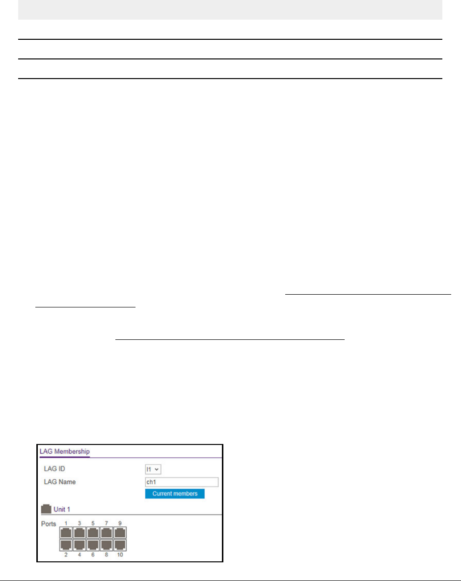
S350 Series 8-Port Gigabit Ethernet Smart Managed Pro Switch Models GS308T and GS310TP
Configure Switching User Manual108
The following table describes the nonconfigurable information displayed on the page.
Table 21. LAG Configuration information
Field Description
LAG ID Identification of the LAG.
Active Ports Indicates the ports that are actively participating in the port channel.
LAG State Indicates whether the link is up or down.
Configure LAG Membership
You can select two or more full-duplex Ethernet links to be aggregated together to form a link
aggregation group (LAG), which is also known as a port channel. The switch can treat the
port channel as a single link.
To configure LAG membership:
1. Connect your computer to the same network as the switch.
You can use a WiFi or wired connection to connect your computer to the network, or
connect directly to a switch that is off-network using an Ethernet cable.
2. Launch a web browser.
3. In the address field of your web browser, enter the IP address of the switch.
If you do not know the IP address of the switch, see Discover or Change the Switch IP
Address on page 12.
Your web browser might display a security message, which you can ignore. For more
information, see Access the Local Browser Interface on page 19.
The login window opens.
4. Enter the switch’s password in the Password field.
The default password is password.
The System Information page displays.
5. Select Switching> LAG > Basic > LAG Membership.

S350 Series 8-Port Gigabit Ethernet Smart Managed Pro Switch Models GS308T and GS310TP
Configure Switching User Manual109
The previous figure shows the LAG Membership page for model GS310TP.
6. From the LAG ID menu, select the LAG ID.
7. In the LAG Name field, enter the name to be assigned to the LAG.
You can enter any string of up to 15 alphanumeric characters. You can also use the
default name.
8. In the Ports table, click each port that you want to include as a member of the selected
LAG.
A selected port is displayed by a check mark.
9. Click the Apply button.
Your settings are saved.
Set the LACP System Priority
You can set the LACP system priority that applies to all LAGs on the switch.
To configure LACP:
1. Connect your computer to the same network as the switch.
You can use a WiFi or wired connection to connect your computer to the network, or
connect directly to a switch that is off-network using an Ethernet cable.
2. Launch a web browser.
3. In the address field of your web browser, enter the IP address of the switch.
If you do not know the IP address of the switch, see Discover or Change the Switch IP
Address on page 12.
Your web browser might display a security message, which you can ignore. For more
information, see Access the Local Browser Interface on page 19.
The login window opens.
4. Enter the switch’s password in the Password field.
The default password is password.
The System Information page displays.
5. Select Switching> LAG > Advanced > LACP Configuration.
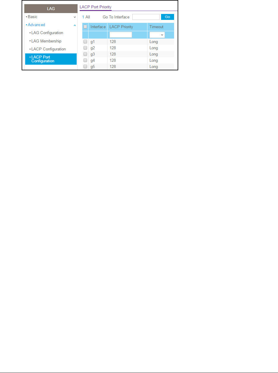
S350 Series 8-Port Gigabit Ethernet Smart Managed Pro Switch Models GS308T and GS310TP
Configure Switching User Manual111
6. Select one or more interfaces by taking one of the following actions:
•To configure a single interface, select the check box associated with the interface, or
type the interface number in the Go To Interface field and click the Go button.
•To configure multiple interfaces with the same settings, select the check box
associated with each interface.
•To configure all interfaces with the same settings, select the check box in the heading
row.
7. In the LACP Priority field, specify the LACP priority value for the selected interfaces.
This value specifies the interface’s link aggregation priority relative to the devices at the
other ends of the links on which link aggregation is enabled. A higher value indicates a
lower priority. The range is 1 to 65535. The default value is 128.
8. In the Timeout field, configure the administrative LACP time-out value:
• Long. Specifies a long time-out value.
•Short. Specifies a short time-out value.
9. Click the Apply button.
Your settings are saved.
Configure VLANs
Adding virtual LAN (VLAN) support to a Layer 2 switch offers some of the benefits of both
bridging and routing. Like a bridge, a VLAN switch forwards traffic based on the Layer 2
header, which is fast, and like a router, it partitions the network into logical segments, which
provides better administration, security, and management of multicast traffic.
By default, all ports on the switch are in the same broadcast domain. VLANs electronically
separate ports on the same switch into separate broadcast domains so that broadcast
packets are not sent to all the ports on a single switch. When you use a VLAN, users can be
grouped by logical function instead of physical location.
Each VLAN in a network is assigned an associated VLAN ID, which appears in the IEEE
802.1Q tag in the Layer 2 header of packets transmitted on a VLAN. An end station can omit
the tag, or the VLAN portion of the tag, in which case the first switch port to receive the

S350 Series 8-Port Gigabit Ethernet Smart Managed Pro Switch Models GS308T and GS310TP
Configure Switching User Manual112
packet can either reject it or insert a tag using its default VLAN ID. A port can handle traffic for
more than one VLAN, but it can support only one default VLAN ID.
You can define VLAN groups stored in the VLAN membership table. The switch supports up
to 64 VLANs.
The following VLANs are preconfigured on the switch and you cannot delete them:
• VLAN 1. The default VLAN of which all ports are members.
•VLAN 2. The default Auto-VoIP VLAN. By default, this VLAN does not include any
members but you can manually add members.
• VLAN 4089. The Auto-Video VLAN. By default, this VLAN does not include any members
but you can manually add members.
Configure VLAN Settings
You can configure the various VLAN settings.
Add a VLAN
To add a VLAN:
1. Connect your computer to the same network as the switch.
You can use a WiFi or wired connection to connect your computer to the network, or
connect directly to a switch that is off-network using an Ethernet cable.
2. Launch a web browser.
3. In the address field of your web browser, enter the IP address of the switch.
If you do not know the IP address of the switch, see Discover or Change the Switch IP
Address on page 12.
Your web browser might display a security message, which you can ignore. For more
information, see Access the Local Browser Interface on page 19.
The login window opens.
4. Enter the switch’s password in the Password field.
The default password is password.
The System Information page displays.
5. Select Switching> VLAN > Basic > VLAN Configuration.

S350 Series 8-Port Gigabit Ethernet Smart Managed Pro Switch Models GS308T and GS310TP
Configure Switching User Manual113
6. In the VLAN ID field, specify the VLAN identifier for the new VLAN.
The range of the VLAN ID can be from 3 to 4093, excluding 4089. (The default VLANs
are 1, 2, and 4089).
7. In the VLAN Name field, specify a name for the VLAN.
The VLAN name can be up to 32 alphanumeric characters long, including blanks. You
cannot change the names of the default VLANs (that is, the VLANs with ID 1, 2, and
4089).
8. The VLAN Type field displays the type of the VLAN that you are configuring.
You cannot change the type of the default VLANs (that is, the VLANs with ID 1, 2, and
4089).
9. Click the Add button.
The VLAN is added to the switch.
Delete a VLAN
To delete a VLAN from the switch:
1. Connect your computer to the same network as the switch.
You can use a WiFi or wired connection to connect your computer to the network, or
connect directly to a switch that is off-network using an Ethernet cable.
2. Launch a web browser.
3. In the address field of your web browser, enter the IP address of the switch.
If you do not know the IP address of the switch, see Discover or Change the Switch IP
Address on page 12.
Your web browser might display a security message, which you can ignore. For more
information, see Access the Local Browser Interface on page 19.
The login window opens.
4. Enter the switch’s password in the Password field.
The default password is password.
The System Information page displays.
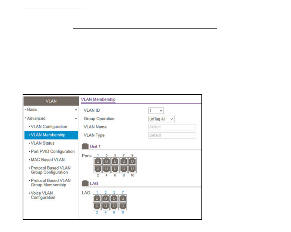
S350 Series 8-Port Gigabit Ethernet Smart Managed Pro Switch Models GS308T and GS310TP
Configure Switching User Manual115
You can also select Switching> VLAN > Advanced > VLAN Configuration.
The VLAN Configuration page displays.
6. Select the Reset Configuration check box.
7. Click the Apply button.
Your settings are saved. Except for the predefined default VLANs, all VLANs are deleted.
Configure VLAN Membership
To configure VLAN membership:
1. Connect your computer to the same network as the switch.
You can use a WiFi or wired connection to connect your computer to the network, or
connect directly to a switch that is off-network using an Ethernet cable.
2. Launch a web browser.
3. In the address field of your web browser, enter the IP address of the switch.
If you do not know the IP address of the switch, see Discover or Change the Switch IP
Address on page 12.
Your web browser might display a security message, which you can ignore. For more
information, see Access the Local Browser Interface on page 19.
The login window opens.
4. Enter the switch’s password in the Password field.
The default password is password.
The System Information page displays.
5. Select Switching > VLAN > Advanced > VLAN Membership.

S350 Series 8-Port Gigabit Ethernet Smart Managed Pro Switch Models GS308T and GS310TP
Configure Switching User Manual116
The previous figure shows the LAG Membership page for model GS310TP.
6. In the VLAN ID menu, select the VLAN ID.
You can select a VLAN that is predefined or that you added (see Add a VLAN on
page 112).
7. In the Group Operation menu, select one of the following options, which applies to all ports
in the VLAN:
• Untag All. For all ports and LAGs that are members of the VLAN, tags are removed
from all egress packets.
• Tag All. For all ports and LAGs that are members of the VLAN, all egress packets are
tagged.
• Remove All. All ports and LAGs are removed from the VLAN.
8. In the Ports table, click each port once, twice, or three times to configure one of the following
modes or reset the port to the default mode:
•T (Tagged). Selects the port as a tagged port in the VLAN. All frames transmitted on
the port are tagged for this VLAN.
•U (Untagged). Selects the port as an untagged port in the VLAN. All frames
transmitted on the port are untagged for this VLAN.
•Blank. The port is excluded from the VLAN.
By default, the selection is blank and none of the ports are a member of the VLAN.
(VLAN 1 is an exception. By default, all ports are untagged members of VLAN 1.)
9. In the LAG table, click each LAG once, twice, or three times to configure one of the following
modes or reset the LAG to the default mode:
•T (Tagged). Selects the LAG as a tagged LAG in the VLAN. All frames transmitted on
the LAG are tagged for this VLAN.
•U (Untagged). Selects the LAG as an untagged LAG in the VLAN. All frames
transmitted on the LAG are untagged for this VLAN.
•Blank. The LAG is excluded from the VLAN.
By default, the selection is blank and none of the LAGs are a member of the VLAN.
(VLAN 1 is an exception. By default, all LAGs are untagged members of VLAN 1.)
10. Click the Apply button.
Your settings are saved.

S350 Series 8-Port Gigabit Ethernet Smart Managed Pro Switch Models GS308T and GS310TP
Configure Switching User Manual117
The following table describes the nonconfigurable information displayed on the page.
Table 22. Advanced VLAN membership
Field Definition
VLAN Name The name for the VLAN that you selected. It can be up to 32 alphanumeric characters long,
including blanks. The names for the following VLANs are predefined:
• VLAN 1. Default.
• VLAN
2. Auto-VoIP.
• VLAN
4089. Auto-Video.
VLAN Type The type of the VLAN you selected:
• Default (VLAN ID = 1). Always present.
• Static. A VLAN that you configured.
• Dynamic. A dynamically created VLAN.
View the VLAN Status
You can view the status of all currently configured VLANs.
To view the VLAN status:
1. Connect your computer to the same network as the switch.
You can use a WiFi or wired connection to connect your computer to the network, or
connect directly to a switch that is off-network using an Ethernet cable.
2. Launch a web browser.
3. In the address field of your web browser, enter the IP address of the switch.
If you do not know the IP address of the switch, see Discover or Change the Switch IP
Address on page 12.
Your web browser might display a security message, which you can ignore. For more
information, see Access the Local Browser Interface on page 19.
The login window opens.
4. Enter the switch’s password in the Password field.
The default password is password.
The System Information page displays.
5. Select Switching > VLAN > Advanced > VLAN Status.

S350 Series 8-Port Gigabit Ethernet Smart Managed Pro Switch Models GS308T and GS310TP
Configure Switching User Manual118
The following table describes the nonconfigurable information displayed on the page.
Table 23. VLAN status
Field Definition
VLAN ID The VLAN identifier (VID) of the VLAN. The range of the VLAN ID is from 1 to 4093.
VLAN Name The name of the VLAN.
VLAN Type The VLAN type:
• Default (VLAN ID = 1). Always present.
• Auto-VoIP (VLAN ID = 2). Always present.
• Auto-VIdeo (VLAN ID = 4089). Always present.
• Static. A VLAN that you configured.
• Dynamic. A dynamically created VLAN.
Member Ports The ports, LAGs, or both that are included in the VLAN.
Configure Port PVID Settings
You can assign a port VLAN ID (PVID) to an interface. The following requirements apply to a
PVID:
•By default, the PVID for each port is 1.
•If you do not specify another value, the default VLAN PVID is used.
•To change the port’s default PVID, you must first create a VLAN that includes the port as
a member (see Configure VLAN Membership on page 115).
To configure PVID settings:
1. Connect your computer to the same network as the switch.
You can use a WiFi or wired connection to connect your computer to the network, or
connect directly to a switch that is off-network using an Ethernet cable.
2. Launch a web browser.
3. In the address field of your web browser, enter the IP address of the switch.
If you do not know the IP address of the switch, see Discover or Change the Switch IP
Address on page 12.
Your web browser might display a security message, which you can ignore. For more
information, see Access the Local Browser Interface on page 19.
The login window opens.
4. Enter the switch’s password in the Password field.
The default password is password.
The System Information page displays.
5. Select Switching> VLAN > Advanced > Port PVID Configuration.

S350 Series 8-Port Gigabit Ethernet Smart Managed Pro Switch Models GS308T and GS310TP
Configure Switching User Manual119
The previous figure shows the PVID Configuration page for model GS310TP.
6. To display information for all physical ports and LAGs, click the All link.
7. Select interfaces by selecting the Interface check boxes next to the interfaces.
You can select multiple interfaces. To select all the interfaces, select the Interface check
box in the heading row.
8. In the PVID field, specify the VLAN ID to assign to untagged or priority-tagged frames
received on the port.
The default is 1.
9. In the VLAN Member field, specify the VLAN ID or list of VLANs of a member port.
VLAN IDs range from 1 to 4093. The default is 1. Use a hyphen (-) to specify a range or a
comma (,) to separate VLAN IDs in a list. Spaces and zeros are not permitted.
10. In the VLAN Tag field, specify the VLAN ID or list of VLANs of a tagged port.
VLAN IDs range from 1 to 4093. Use a hyphen (-) to specify a range or a comma (,) to
separate VLAN IDs in a list. Spaces and zeros are not permitted. You can specify port
tagging for the VLAN only if the port that you want to add as a tagged port is also member
of the VLAN. To reset the VLAN tag configuration to the defaults, use the None keyword.
11. From the Acceptable Frame menu, specify one if the following types of frames that can be
received on the port:
• Admit All. Untagged frames or priority-tagged frames that are received on the port
are accepted and assigned the value of the port VLAN ID for the port. This is the
default selection.
• VLAN Only. Untagged frames or priority-tagged frames that are received on the port
are discarded.
•Admit Untagged Only. Untagged frames that are received on the port are accepted.
With the Admit All and VLAN Only selections, VLAN-tagged frames are forwarded in
accordance to the 802.1Q VLAN specification.
12. From the Ingress Filtering menu, select one of the following options:
• Enable. The frame is discarded if the port is not a member of the VLAN with which
this frame is associated. In a tagged frame, the VLAN is identified by the VLAN ID in
the tag. In an untagged frame, the VLAN is the port VLAN ID specified for the port that
received this frame.

S350 Series 8-Port Gigabit Ethernet Smart Managed Pro Switch Models GS308T and GS310TP
Configure Switching User Manual120
• Disable. All frames are forwarded in accordance with the 802.1Q VLAN bridge
specification. The default is Disable.
13. In the Port Priority field, specify the default 802.1p priority assigned to untagged packets
arriving at the port.
You can enter a number from 0 to 7.
14. Click the Apply button.
Your settings are saved.
The following table describes the nonconfigurable fields.
Table 24. Nonconfigurable fields on the PVID Configuration page
Field Description
Current Ingress Filtering Indicates whether ingress filtering is enabled for the interface.
Untagged VLANs The number of untagged VLANs for the interface.
Tagged VLANs The number of tagged VLANs for the interface.
Forbidden VLANs The number of forbidden VLANs for the interface.
Dynamic VLANs The number of dynamically added VLANs for the interface.
Configure a MAC-Based VLAN
The MAC-Based VLAN feature allows incoming untagged packets to be assigned to a VLAN
and thus classify traffic based on the source MAC address of the packet.
You define a MAC-to-VLAN mapping by configuring an entry in the MAC-to-VLAN table. An
entry is specified through a source MAC address and a VLAN ID. The MAC-to-VLAN
configurations are shared across all ports of the switch (that is, a system-wide table exists
with MAC address–to–VLAN ID mappings).
When untagged or priority-tagged packets arrive at the switch and entries exist in the
MAC-to-VLAN table, the source MAC address of the packet is looked up. If an entry is found,
the corresponding VLAN ID is assigned to the packet. If the packet is already priority-tagged,
it maintains this value. Otherwise, the priority is set to zero. The assigned VLAN ID is verified
against the VLAN table. If the VLAN is valid, ingress processing on the packet continues.
Otherwise, the packet is dropped. This implies that you can configure a MAC address
mapping to a VLAN that you did not yet create on the switch.
Add a MAC-Based VLAN
To add a MAC-based VLAN:
1. Connect your computer to the same network as the switch.
You can use a WiFi or wired connection to connect your computer to the network, or
connect directly to a switch that is off-network using an Ethernet cable.

S350 Series 8-Port Gigabit Ethernet Smart Managed Pro Switch Models GS308T and GS310TP
Configure Switching User Manual121
2. Launch a web browser.
3. In the address field of your web browser, enter the IP address of the switch.
If you do not know the IP address of the switch, see Discover or Change the Switch IP
Address on page 12.
Your web browser might display a security message, which you can ignore. For more
information, see Access the Local Browser Interface on page 19.
The login window opens.
4. Enter the switch’s password in the Password field.
The default password is password.
The System Information page displays.
5. Select Switching> VLAN > Advanced > MAC Based VLAN.
6. In the MAC Address field, enter a MAC address to be bound to a VLAN ID.
This field is configurable only when a MAC-based VLAN is created.
7. In the VLAN ID field, specify a VLAN ID in the range from 1 to 4093.
8. Click the Add button.
The MAC address is added to the VLAN mapping.
Delete a MAC Address From VLAN Mapping
To delete a MAC address from VLAN mapping:
1. Connect your computer to the same network as the switch.
You can use a WiFi or wired connection to connect your computer to the network, or
connect directly to a switch that is off-network using an Ethernet cable.
2. Launch a web browser.
3. In the address field of your web browser, enter the IP address of the switch.
If you do not know the IP address of the switch, see Discover or Change the Switch IP
Address on page 12.
Your web browser might display a security message, which you can ignore. For more
information, see Access the Local Browser Interface on page 19.
The login window opens.
4. Enter the switch’s password in the Password field.
The default password is password.

S350 Series 8-Port Gigabit Ethernet Smart Managed Pro Switch Models GS308T and GS310TP
Configure Switching User Manual122
The System Information page displays.
5. Select Switching> VLAN > Advanced > MAC Based VLAN.
The MAC Based VLAN Configuration page displays.
6. In the MAC Address field, enter a MAC address.
This field is configurable only when a MAC-based VLAN exists.
7. In the VLAN ID field, specify a VLAN ID in the range from 1 to 4093.
8. Click the Delete button.
The MAC address is removed from the VLAN mapping.
Configure Protocol-Based VLAN Groups
You can use a protocol-based VLAN to define filtering criteria for untagged packets. By
default, if you do not configure any port-based (IEEE 802.1Q) or protocol-based VLANs,
untagged packets are assigned to VLAN 1. You can override this behavior by defining either
port-based VLANs or protocol-based VLANs, or both. Tagged packets are always handled
according to the IEEE 802.1Q standard and are not included in protocol-based VLANs.
If you assign a port to a protocol-based VLAN for a specific protocol, untagged frames that
arrive on that port for that protocol are assigned the protocol-based VLAN ID. Untagged
frames that arrive on the port for other protocols are assigned the port VLAN ID, either the
default PVID (1) or a PVID you specifically assigned to the port (see Configure Port PVID
Settings on page 118).
You define a protocol-based VLAN by creating a group. Each group forms a one-to-one
relationship with a VLAN ID, can include one to three protocol definitions, and can include
multiple ports. When you create a group, you specify a name and a group ID is assigned
automatically.
To configure a protocol-based VLAN group:
1. Connect your computer to the same network as the switch.
You can use a WiFi or wired connection to connect your computer to the network, or
connect directly to a switch that is off-network using an Ethernet cable.
2. Launch a web browser.
3. In the address field of your web browser, enter the IP address of the switch.
If you do not know the IP address of the switch, see Discover or Change the Switch IP
Address on page 12.
Your web browser might display a security message, which you can ignore. For more
information, see Access the Local Browser Interface on page 19.
The login window opens.
4. Enter the switch’s password in the Password field.
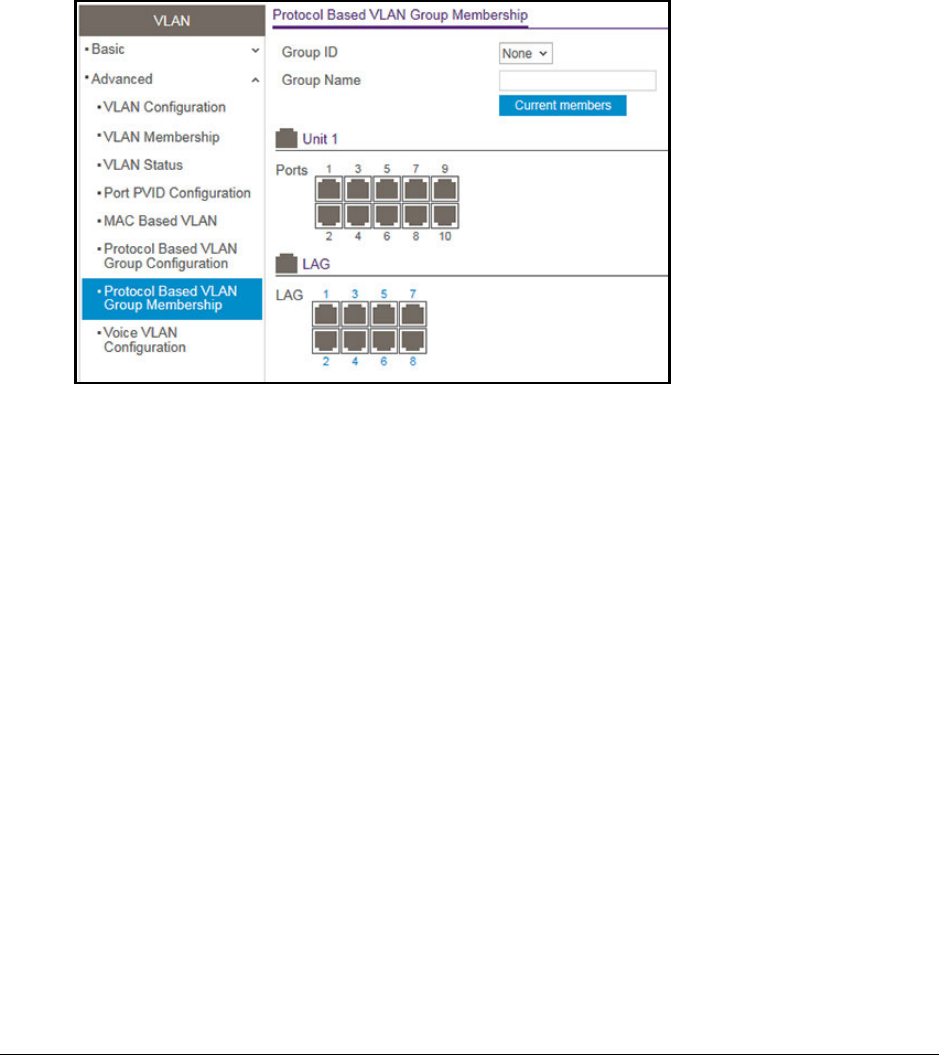
S350 Series 8-Port Gigabit Ethernet Smart Managed Pro Switch Models GS308T and GS310TP
Configure Switching User Manual124
The login window opens.
4. Enter the switch’s password in the Password field.
The default password is password.
The System Information page displays.
5. Select Switching> VLAN > Advanced > Protocol Based VLAN Group Membership.
The previous figure shows the Protocol Based VLAN Group Membership page for model
GS310TP.
6. From the Group ID menu, select the protocol-based VLAN group ID.
The Group Name field shows the name that is associated with the group.
7. In the Ports table and LAG table, click each port and LAG that you want to include in the
protocol-based VLAN group.
A protocol-based VLAN group can include both port and LAGs. A selected port or LAG is
displayed by a check mark.
8. Click the Apply button
Your settings are saved.
9. To display the current numbers in the selected protocol-based VLAN group, click the
Current Members button.

S350 Series 8-Port Gigabit Ethernet Smart Managed Pro Switch Models GS308T and GS310TP
Configure Switching User Manual126
•To configure multiple interfaces with the same settings, select the check box
associated with each interface.
•To configure all interfaces with the same settings, select the check box in the heading
row.
8. From the Interface Mode menu, select the voice VLAN mode for selected interfaces:
• Disable. This is the default value.
•None. Allow the IP phone to use its own configuration to send untagged voice traffic.
•VLAN ID. Configure the phone to send tagged voice traffic. You must enter the VLAN
ID in the Value field (see the next step).
• Dot1p. Configure voice VLAN 802.1p priority tagging for voice traffic. You must enter
the dot1p value in the Value field (see the next step).
• Untagged. Configure the phone to send untagged voice traffic.
9. In the Value field, enter the VLAN ID or dot1p value.
This field is enabled only if you select VLAN ID or Dot1p from the Interface Mode menu.
10. In the CoS Override Mode field, select Disable or Enable.
The default is Disable.
11. In the Authentication Mode field, select Enable or Disable.
The default is Enable. When the authentication mode is enabled, voice traffic is allowed
on an unauthorized voice VLAN port. When the authentication mode is disabled, devices
are authorized through dot1x.
Note: Authentication through dot1x is possible only if dot1x is enabled.
12. In the DSCP Value field, configure the Voice VLAN DSCP value for the port.
The range is from 0 to 64. The default value is 0.
13. Click the Apply button.
Your settings are saved.
The Operational State field displays the operational status of the voice VLAN on an
interface.
Configure Auto-VoIP
Voice over Internet Protocol (VoIP) enables telephone calls over a data network. Because
voice traffic is typically more time-sensitive than data traffic, the Auto-VoIP feature provides a
classification for voice packets so that they can be prioritized above data packets, allowing
the switch to provide better Quality of Service (QoS). With the Auto-VoIP feature, voice
prioritization is provided based on the SIP call-control protocol or OUI bits.

S350 Series 8-Port Gigabit Ethernet Smart Managed Pro Switch Models GS308T and GS310TP
Configure Switching User Manual127
Configure Protocol-Based Port Settings for VoIP
To prioritize time-sensitive voice traffic over data traffic, protocol-based Auto-VoIP checks for
packets carrying the Session Initiation Protocol (SIP) VoIP protocol.
VoIP frames that are received on ports that for which the Auto-VoIP feature is enabled are
marked with the specified CoS traffic class value.
To configure protocol-based port settings for VoIP:
1. Connect your computer to the same network as the switch.
You can use a WiFi or wired connection to connect your computer to the network, or
connect directly to a switch that is off-network using an Ethernet cable.
2. Launch a web browser.
3. In the address field of your web browser, enter the IP address of the switch.
If you do not know the IP address of the switch, see Discover or Change the Switch IP
Address on page 12.
Your web browser might display a security message, which you can ignore. For more
information, see Access the Local Browser Interface on page 19.
The login window opens.
4. Enter the switch’s password in the Password field.
The default password is password.
The System Information page displays.
5. Select Switching > Auto-VoIP > Protocol-based > Port Settings.
6. From the Prioritization Type menu, select Traffic Class or Remark.
This selection specifies the type of prioritization.

S350 Series 8-Port Gigabit Ethernet Smart Managed Pro Switch Models GS308T and GS310TP
Configure Switching User Manual128
7. From the Class Value menu, specify the CoS class value to be reassigned for packets that
the voice VLAN receives.
8. Click the Apply button.
Your settings are saved.
Configure Auto-VoIP OUI-Based Properties
With Organizationally Unique Identifier (OUI)–based Auto-VoIP, voice prioritization is
provided based on OUI bits.
To configure Auto-VoIP OUI-based properties:
1. Connect your computer to the same network as the switch.
You can use a WiFi or wired connection to connect your computer to the network, or
connect directly to a switch that is off-network using an Ethernet cable.
2. Launch a web browser.
3. In the address field of your web browser, enter the IP address of the switch.
If you do not know the IP address of the switch, see Discover or Change the Switch IP
Address on page 12.
Your web browser might display a security message, which you can ignore. For more
information, see Access the Local Browser Interface on page 19.
The login window opens.
4. Enter the switch’s password in the Password field.
The default password is password.
The System Information page displays.
5. Select Switching > Auto-VoIP > OUI-based > Properties.
The OUI-Based Properties page displays.
6. In the Auto-VoIP VLAN ID field, enter the VoIP VLAN ID of the switch.
The default Auto-VoIP VLAN ID is 2. You can use that VLAN ID or create another VLAN
ID for Auto-VoIP.
7. From the OUI-based priority menu, select the OUI-based priority of the switch, from 0 to 7.
The default value is 7.
8. Click the Apply button.
Your settings are saved.

S350 Series 8-Port Gigabit Ethernet Smart Managed Pro Switch Models GS308T and GS310TP
Configure Switching User Manual130
8. Click the Apply button.
Your settings are saved.
The Operational Status field displays the current operational status of an interface.
Manage the OUI Table
Device hardware manufacturers can include an OUI in a network adapter to help identify a
hardware device. The OUI is a unique 24-bit number assigned by the IEEE registration
authority. The switch comes preconfigured with the following OUIs that identify the IP phone
manufacturer:
•00:01:E3: SIEMENS
•00:03:6B: CISCO1
•00:12:43: CISCO2
•00:60:B9: NITSUKO
•00:D0:1E: PINTEL
•00:E0:75: VERILINK
•00:E0:BB: 3COM
•00:04:0D: AVAYA1
•00:1B:4F: AVAYA2
You can select an existing OUI or add a new OUI and description to identify the IP phones on
the network.
Configure the OUI Table
To configure the OUI Table:
1. Connect your computer to the same network as the switch.
You can use a WiFi or wired connection to connect your computer to the network, or
connect directly to a switch that is off-network using an Ethernet cable.
2. Launch a web browser.
3. In the address field of your web browser, enter the IP address of the switch.
If you do not know the IP address of the switch, see Discover or Change the Switch IP
Address on page 12.
Your web browser might display a security message, which you can ignore. For more
information, see Access the Local Browser Interface on page 19.
The login window opens.
4. Enter the switch’s password in the Password field.
The default password is password.
The System Information page displays.

S350 Series 8-Port Gigabit Ethernet Smart Managed Pro Switch Models GS308T and GS310TP
Configure Switching User Manual131
5. Select Switching > Auto-VoIP > OUI-based > OUI Table.
The OUI Table page displays.
6. In the Telephony OUI(s) field, specify the VoIP OUI prefix to be added in the format
AA:BB:CC.
You can configure up to 32 OUIs.
7. In the Description field, enter the description for the OUI.
The maximum length of description is 32 characters.
8. Click the Add button.
The telephony OUI entry is added.
Delete One or More OUI Prefixes From the OUI Table
To delete one or more OUI prefixes from the OUI table:
1. Connect your computer to the same network as the switch.
You can use a WiFi or wired connection to connect your computer to the network, or
connect directly to a switch that is off-network using an Ethernet cable.
2. Launch a web browser.
3. In the address field of your web browser, enter the IP address of the switch.
If you do not know the IP address of the switch, see Discover or Change the Switch IP
Address on page 12.
Your web browser might display a security message, which you can ignore. For more
information, see Access the Local Browser Interface on page 19.
The login window opens.
4. Enter the switch’s password in the Password field.
The default password is password.
The System Information page displays.
5. Select Switching > Auto-VoIP > OUI-based > OUI Table.
The OUI Table page displays.
6. Select the check box next to each OUI prefix to be removed.
7. Click the Delete button.
The telephony OUI entries are removed.

S350 Series 8-Port Gigabit Ethernet Smart Managed Pro Switch Models GS308T and GS310TP
Configure Switching User Manual132
Display the Auto-VoIP Status
You can display the Auto-VoIP status.
To view the Auto-VoIP status:
1. Connect your computer to the same network as the switch.
You can use a WiFi or wired connection to connect your computer to the network, or
connect directly to a switch that is off-network using an Ethernet cable.
2. Launch a web browser.
3. In the address field of your web browser, enter the IP address of the switch.
If you do not know the IP address of the switch, see Discover or Change the Switch IP
Address on page 12.
Your web browser might display a security message, which you can ignore. For more
information, see Access the Local Browser Interface on page 19.
The login window opens.
4. Enter the switch’s password in the Password field.
The default password is password.
The System Information page displays.
5. Select Switching > Auto-VoIP > Auto-VoIP Status.
The Auto-VoIP Status page displays.
6. To refresh the page with the latest information about the switch, click the Update button.
The following table describes the nonconfigurable Auto-VoIP status information.
Table 25. Auto-VoIP status
Field Description
Auto-VoIP VLAN ID The Auto-VoIP VLAN ID.
Maximum Number of Voice
Channels Supported The maximum number of voice channels supported.
Number of Voice Channels
Detected The number of VoIP channels prioritized successfully.

S350 Series 8-Port Gigabit Ethernet Smart Managed Pro Switch Models GS308T and GS310TP
Configure Switching User Manual133
Configure Spanning Tree Protocol
The Spanning Tree Protocol (STP) provides a tree topology for any arrangement of network
devices. STP also provides one path between end stations on a network, eliminating loops.
STP (also referred to as “classic” STP) provides a single path between end stations, avoiding
and eliminating loops. For information about configuring the global STP settings for the
switch, see Configure the STP Settings and View the STP Status on page 133.
The switch support the following spanning tree versions:
• CST. Common STP. For information on configuring CST, see Configure and View the
CST Settings on page 135 and Configure and View the CST Port Settings on page 137.
• MSTP. Multiple Spanning Tree Protocol (MSTP, also referred to as MST) supports
multiple instances of spanning tree to efficiently channel VLAN traffic over different
interfaces. For information on configuring MSTP, see Manage MST Settings on page 142
and Configure and View the Port Settings for an MST Instance on page 144.
• RSTP. Rapid STP. Each instance of the spanning tree behaves in the manner specified in
IEEE 802.1w, Rapid Spanning Tree (RSTP), with slight modifications in the working but
not the end effect (chief among the effects is the rapid transitioning of the port to the
forwarding state). For information on viewing the RSTP state, see View Rapid STP
Information on page 141.
The difference between the RSTP and the traditional STP (IEEE 802.1D) is the ability to
configure and recognize full-duplex connectivity and ports that are connected to end
stations, resulting in rapid transitioning of the port to the forwarding state and the
suppression of Topology Change Notification. These features are represented by the
parameters pointtopoint and edgeport. MSTP is compatible with both RSTP and STP. It
behaves in a way that is appropriate for STP and RSTP bridges. An MSTP bridge can be
configured to behave entirely as an RSTP bridge or an STP bridge.
Note: For two bridges to be in the same region, the force version must be
802.1s and their configuration names, digest keys, and revision levels
must match. For additional information about regions and their effect
on network topology, refer to the IEEE 802.1Q standard.
Configure the STP Settings and View the STP Status
You can configure the STP settings and view the STP status on the switch.
To configure the STP settings and view the STP status:
1. Connect your computer to the same network as the switch.
You can use a WiFi or wired connection to connect your computer to the network, or
connect directly to a switch that is off-network using an Ethernet cable.

S350 Series 8-Port Gigabit Ethernet Smart Managed Pro Switch Models GS308T and GS310TP
Configure Switching User Manual134
2. Launch a web browser.
3. In the address field of your web browser, enter the IP address of the switch.
If you do not know the IP address of the switch, see Discover or Change the Switch IP
Address on page 12.
Your web browser might display a security message, which you can ignore. For more
information, see Access the Local Browser Interface on page 19.
The login window opens.
4. Enter the switch’s password in the Password field.
The default password is password.
The System Information page displays.
5. Select Switching > STP > Basic > STP Configuration.
6. Configure the following global settings for the switch:
a. Spanning Tree State. Enable or disable the spanning tree operation on the switch.
By default, spanning tree operation is disabled.
b. STP Operation Mode. Specify the STP version for the switch.
The options are STP, RSTP, and MSTP. The default is RSTP.
c. Configuration
Name. Specify a name to identify the STP, RSTP, or MSTP
configuration.
The name can be up to 32 alphanumeric characters.
d. Configuration
Revision Level. Specify an identifier to identify the STP, RSTP, or
MSTP configuration.
The values can be from 0 to 65535. The default value is 0.
e. Forward BPDU while STP Disabled. Enable or disable the bridge protocol data unit
(BPDU) flood.
This setting specifies whether spanning tree BPDUs are forwarded while spanning
tree is disabled on the switch.
7. Click the Apply button.
Your settings are saved.

S350 Series 8-Port Gigabit Ethernet Smart Managed Pro Switch Models GS308T and GS310TP
Configure Switching User Manual139
13. In the External Port Path Cost field, set the external path cost to a new value for the
specified port in the spanning tree.
The value range is 0 to 200000000. The default is 0.
14. Click the Apply button.
Your settings are saved.
15. To refresh the page with the latest information about the switch, click the Update button.
The following table describes the nonconfigurable information displayed on the page.
Table 28. CST port configuration
Field Description
Port State The forwarding state of the port. The default is Disabled.
Port ID The port identifier for the specified port within the CST. It is made up from the port
priority and the interface number of the port.
Hello Timer The value of the setting for the CST. The default is 2 seconds.
View the CST Port Status
You can display the common spanning tree (CST) and internal spanning tree for a specific
port on the switch.
To view the CST port status:
1. Connect your computer to the same network as the switch.
You can use a WiFi or wired connection to connect your computer to the network, or
connect directly to a switch that is off-network using an Ethernet cable.
2. Launch a web browser.
3. In the address field of your web browser, enter the IP address of the switch.
If you do not know the IP address of the switch, see Discover or Change the Switch IP
Address on page 12.
Your web browser might display a security message, which you can ignore. For more
information, see Access the Local Browser Interface on page 19.
The login window opens.
4. Enter the switch’s password in the Password field.
The default password is password.
The System Information page displays.
5. Select Switching > STP > Advanced > CST Port Status.

S350 Series 8-Port Gigabit Ethernet Smart Managed Pro Switch Models GS308T and GS310TP
Configure Switching User Manual140
6. To refresh the page with the latest information about the switch, click the Update button.
The following table describes the CST Status information displayed on the page.
Table 29. CST port status
Field Description
Interface The physical port or LAG that is associated with the CST.
Port Role Each MST bridge port that is enabled is assigned a port role for each
spanning tree. The port role can be Root, Designated, Alternate, Backup,
Master, or Disabled.
Designated Root The root bridge for the CST. It is made up using the bridge priority and the
base MAC address of the bridge.
Designated Cost The path cost offered to the LAN by the designated port.
Designated Bridge The identifier of the bridge with the designated port. It is made up using the
bridge priority and the base MAC address of the bridge.
Designated Port The port identifier on the designated bridge that offers the lowest cost to the
LAN. It is made up from the port priority and the interface number of the port.
Topology Change Acknowledge Identifies whether the topology change acknowledgement flag is set for the
next BPDU to be transmitted for the port. It is either True or False.
Edge port Indicates whether the port is enabled as an edge port. It is either Enabled or
Disabled.
Point-to-point MAC The derived value of the point-to-point status.
CST Regional Root The bridge identifier of the CST regional root. It is made up using the bridge
priority and the base MAC address of the bridge.
CST Path Cost The path cost to the CST regional root.
Port Forwarding State The forwarding state of the port.

S350 Series 8-Port Gigabit Ethernet Smart Managed Pro Switch Models GS308T and GS310TP
Configure Switching User Manual141
View Rapid STP Information
You can view information about the Rapid Spanning Tree (RSTP) port status.
To view information about RSTP:
1. Connect your computer to the same network as the switch.
You can use a WiFi or wired connection to connect your computer to the network, or
connect directly to a switch that is off-network using an Ethernet cable.
2. Launch a web browser.
3. In the address field of your web browser, enter the IP address of the switch.
If you do not know the IP address of the switch, see Discover or Change the Switch IP
Address on page 12.
Your web browser might display a security message, which you can ignore. For more
information, see Access the Local Browser Interface on page 19.
The login window opens.
4. Enter the switch’s password in the Password field.
The default password is password.
The System Information page displays.
5. Select Switching > STP > Advanced > RSTP.
6. To refresh the page with the latest information about the switch, click the Update button.
The following table describes the Rapid STP Status information displayed on the page.
Table 30. Rapid STP status information
Field Description
Interface The physical or port channel interfaces associated with VLANs associated with the CST.
Role Each MST bridge port that is enabled is assigned a port role for each spanning tree. The port
role can be Root, Designated, Alternate, Backup Master, or Disabled.
Mode Specifies the spanning tree operation mode. Different modes are STP, RSTP, and MSTP.
Fast Link Indicates whether the port is enabled as an edge port.
Status The forwarding state of the port.
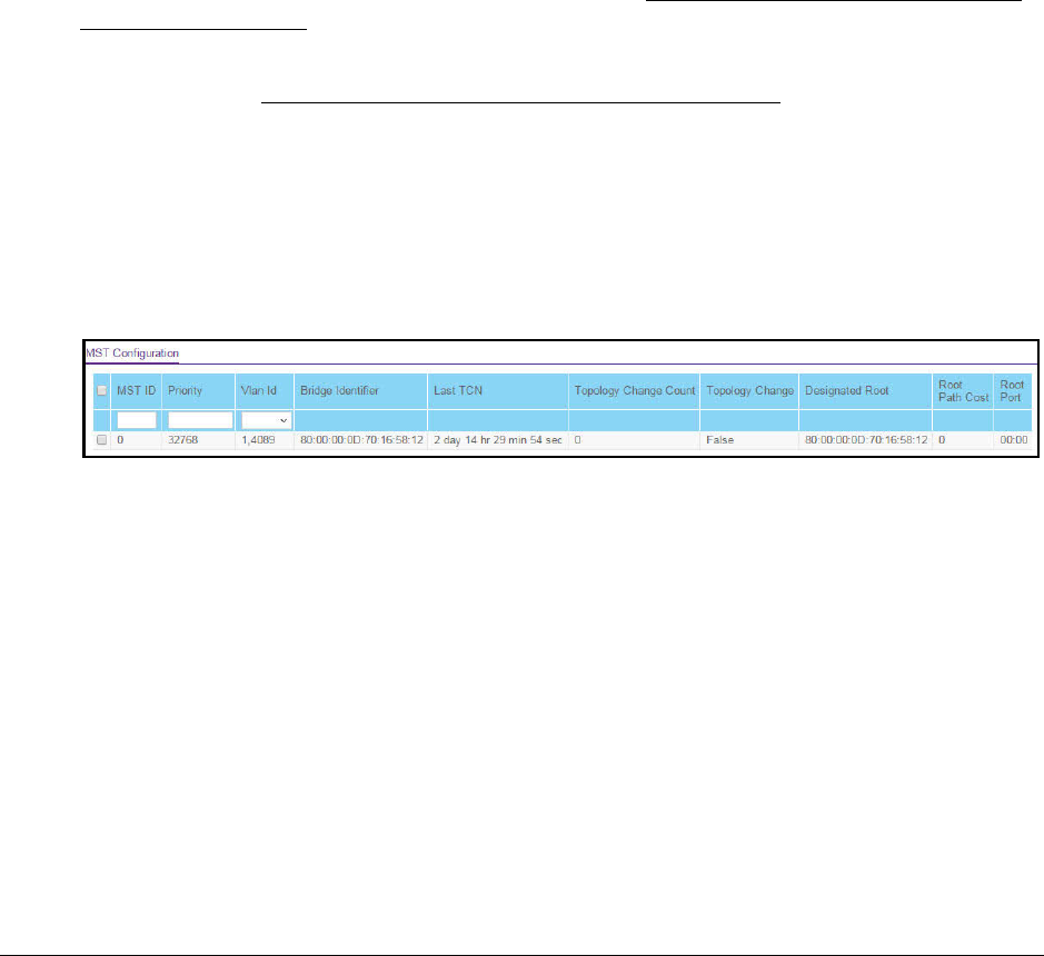
S350 Series 8-Port Gigabit Ethernet Smart Managed Pro Switch Models GS308T and GS310TP
Configure Switching User Manual142
Manage MST Settings
You can configure a multiple spanning tree (MST) on the switch.
Configure an MST Instance
To configure an MST instance:
1. Connect your computer to the same network as the switch.
You can use a WiFi or wired connection to connect your computer to the network, or
connect directly to a switch that is off-network using an Ethernet cable.
2. Launch a web browser.
3. In the address field of your web browser, enter the IP address of the switch.
If you do not know the IP address of the switch, see Discover or Change the Switch IP
Address on page 12.
Your web browser might display a security message, which you can ignore. For more
information, see Access the Local Browser Interface on page 19.
The login window opens.
4. Enter the switch’s password in the Password field.
The default password is password.
The System Information page displays.
5. Select Switching > STP > Advanced > MST Configuration.
6. Configure the MST values:
• MST ID. Specify the ID of the MST to create. The range is from 1 to 4094. This is
visible only when the select option of the MST ID select box is selected.
•Priority. The bridge priority value for the MST. When switches or bridges are running
STP, each is assigned a priority. After exchanging BPDUs, the switch with the lowest
priority value becomes the root bridge. The bridge priority is a multiple of 4096. If you
specify a priority that is not a multiple of 4096, the priority is automatically set to the
next lowest priority that is a multiple of 4096. For example, if you set the priority to any
value between 0 and 4095, the switch automatically sets the value to 0. The default
value is 32768. The range is from 0 to 61440.
• VLAN Id. The menu includes all VLANs that are configured on the switch. You can
select VLANs that must be associated with the MST instance or clear VLANs that are
already associated with the MST instance.
7. Click the Add button.

S350 Series 8-Port Gigabit Ethernet Smart Managed Pro Switch Models GS308T and GS310TP
Configure Switching User Manual146
9. Click the Apply button.
Your settings are saved.
10. To refresh the page with the latest information about the switch, click the Update button.
The following table describes the read-only MST port configuration information displayed on
the Spanning Tree CST Configuration page.
Table 32. MST port status information
Field Description
Auto Calculated Port Path
Cost Indicates whether the path cost is automatically calculated (Enabled) or not
(Disabled). Path cost is calculated based on the link speed of the port if the
configured value for Port Path Cost is zero.
Port ID The port identifier for the specified port within the selected MST instance. It is
made up from the port priority and the interface number of the port.
Port Up Time Since Counters
Last Cleared The time since the counters were last cleared, displayed in days, hours,
minutes, and seconds.
Port Mode The Spanning Tree Protocol administrative mode that is associated with the port
or port channel. The option is Enable or Disable.
Port Forwarding State The current STP state of a port. If enabled, the port state determines what
forwarding action is taken on traffic. The options are as follows:
• Disabled. STP is currently disabled on the port. The port forwards traffic
while learning MAC addresses.
• Discarding. The port is currently blocked. The port cannot forward traffic
nor can it learn MAC addresses.
• Manual Forwarding. STP is currently disabled on the port. The port
forwards traffic while learning MAC addresses.
• Learning. The port is currently in the learning mode. The port cannot
forward traffic. However, it can learn new MAC addresses.
• Forwarding. The port is currently in the forwarding mode. The port can
forward traffic and learn new MAC addresses.
Port Role Each MST bridge port that is enabled is assigned a port role for each spanning
tree. The port role can be Root, Designated, Alternate, Backup, Master, or
Disabled.
Designated Root The root bridge for the selected MST instance. It is made up using the bridge
priority and the base MAC address of the bridge.
Designated Cost The cost of the port participating in the STP topology. Ports with a lower cost are
less likely to be blocked if STP detects loops.
Designated Bridge The bridge identifier of the bridge with the designated port. It is made up using
the bridge priority and the base MAC address of the bridge.
Designated Port The port identifier on the designated bridge that offers the lowest cost to the
LAN. It is made up from the port priority and the interface number of the port.

S350 Series 8-Port Gigabit Ethernet Smart Managed Pro Switch Models GS308T and GS310TP
Configure Switching User Manual153
The following table displays information about the global IGMP snooping status and statistics
on the page.
Table 36. IGMP Snooping Configuration information
Field Description
Multicast Control Frame Count The number of multicast control frames that are processed by the CPU.
Interfaces Enabled for IGMP
Snooping The interfaces that are enabled for IGMP snooping.
VLAN IDs Enabled For IGMP
Snooping The IDs of the VLANs that are enabled for IGMP snooping.
VLAN IDs Enabled For IGMP
Snooping Querier The IDs of the VLANs that are enabled for IGMP snooping querier.
Configure IGMP Snooping for Interfaces
To configure IGMP snooping for interfaces:
1. Connect your computer to the same network as the switch.
You can use a WiFi or wired connection to connect your computer to the network, or
connect directly to a switch that is off-network using an Ethernet cable.
2. Launch a web browser.
3. In the address field of your web browser, enter the IP address of the switch.
If you do not know the IP address of the switch, see Discover or Change the Switch IP
Address on page 12.
Your web browser might display a security message, which you can ignore. For more
information, see Access the Local Browser Interface on page 19.
The login window opens.
4. Enter the switch’s password in the Password field.
The default password is password.
The System Information page displays.
5. Select Switching> Multicast > IGMP Snooping > Interface Configuration.

S350 Series 8-Port Gigabit Ethernet Smart Managed Pro Switch Models GS308T and GS310TP
Configure Switching User Manual161
7. In the VLAN ID field, enter the VLAN ID.
8. From the Multicast Router menu, select Enable or Disable.
9. Click the Apply button.
Your settings are saved.
IGMP Snooping Querier Overview
IGMP snooping requires that one central switch or router periodically queries all end-devices
on the network to announce their multicast memberships. This central device is the IGMP
querier. The IGMP query responses, known as IGMP reports, keep the switch updated with
the current multicast group membership on a port-by-port basis. If the switch does not
receive updated membership information in a timely fashion, it stops forwarding multicasts to
the port where the end device is located.
You can configure and display information about IGMP snooping queriers on the network
and, separately, on VLANs.
Configure an IGMP Snooping Querier
You can configure the settings for an IGMP snooping querier.
To configure the settings for an IGMP snooping querier:
1. Connect your computer to the same network as the switch.
You can use a WiFi or wired connection to connect your computer to the network, or
connect directly to a switch that is off-network using an Ethernet cable.
2. Launch a web browser.
3. In the address field of your web browser, enter the IP address of the switch.
If you do not know the IP address of the switch, see Discover or Change the Switch IP
Address on page 12.
Your web browser might display a security message, which you can ignore. For more
information, see Access the Local Browser Interface on page 19.
The login window opens.
4. Enter the switch’s password in the Password field.
The default password is password.
The System Information page displays.
5. Select Switching> Multicast > IGMP Snooping Querier > Querier Configuration.
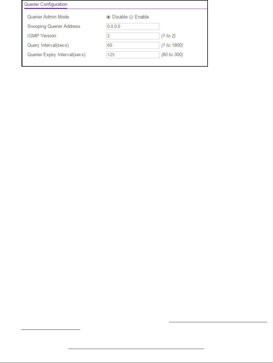
S350 Series 8-Port Gigabit Ethernet Smart Managed Pro Switch Models GS308T and GS310TP
Configure Switching User Manual162
6. Configure the following settings:
• Querier Admin Mode. Enable or disable IGMP snooping for the switch. The default is
Disable.
• Snooping Querier IP Address. Enter the snooping querier IP address to be used as
the source address in periodic IGMP queries. This address is used when no address
is configured on the VLAN on which a query is being sent.
• IGMP Version. Specify the IGMP protocol version used in periodic IGMP queries.
The range is 1 to 2. The default value is 2.
• Query Interval(secs). Specify the time interval in seconds between periodic queries
sent by the snooping querier. The query interval must be in the range from 1 to 1800.
The default value is 60 seconds.
•Querier Expiry Interval(secs). Specify the time interval in seconds after which the
last querier information is removed. The querier expiry interval must be in the range
from 60 to 300. The default value is 125 seconds.
7. Click the Apply button.
Your settings are saved.
Configure an IGMP Snooping Querier for VLANs
You can configure IGMP queriers for use with VLANs on the network.
To configure IGMP snooping for a VLAN ID:
1. Connect your computer to the same network as the switch.
You can use a WiFi or wired connection to connect your computer to the network, or
connect directly to a switch that is off-network using an Ethernet cable.
2. Launch a web browser.
3. In the address field of your web browser, enter the IP address of the switch.
If you do not know the IP address of the switch, see Discover or Change the Switch IP
Address on page 12.
Your web browser might display a security message, which you can ignore. For more
information, see Access the Local Browser Interface on page 19.

S350 Series 8-Port Gigabit Ethernet Smart Managed Pro Switch Models GS308T and GS310TP
Configure Switching User Manual163
The login window opens.
4. Enter the switch’s password in the Password field.
The default password is password.
The System Information page displays.
5. Select Switching> Multicast > IGMP Snooping Querier > Querier VLAN Configuration.
6. From the VLAN ID menu, select New Entry.
7. Configure the following settings:
• VLAN ID. The VLAN ID for which the IGMP snooping querier must be enabled. You
can select an existing VLAN only.
• Querier Election Participate Mode. Enable or disable the querier mode:
- Disable. Upon seeing another querier of the same version in the VLAN, the
snooping querier moves to the non-querier state.
- Enable. The snooping querier participates in querier election, in which the lowest
IP address operates as the querier in that VLAN. The other querier moves to
non-querier state.
• Snooping Querier VLAN Address. Specify the snooping querier IP address to be
used as the source address in periodic IGMP queries that are sent to the VLAN.
8. Click the Apply button.
Your settings are saved.
Display IGMP Snooping Querier for VLAN Status
To display querier VLAN status:
1. Connect your computer to the same network as the switch.
You can use a WiFi or wired connection to connect your computer to the network, or
connect directly to a switch that is off-network using an Ethernet cable.
2. Launch a web browser.
3. In the address field of your web browser, enter the IP address of the switch.
If you do not know the IP address of the switch, see Discover or Change the Switch IP
Address on page 12.

S350 Series 8-Port Gigabit Ethernet Smart Managed Pro Switch Models GS308T and GS310TP
Configure Switching User Manual169
Configure Layer 2 Loop Protection
Loops inside a network are costly because they consume resources and reduce the
performance of the network. Detecting loops manually can be cumbersome.
The switch can automatically identify loops in the network. You can enable loop protection
per port or globally.
If loop protection is enabled, the switch sends predefined PDU packets to a Layer 2
broadcast destination address (FF:FF:FF:FF:FF:FF) on all ports for which the feature is
enabled. You can selectively disable PDU packet transmission for loop protection on specific
ports even while port loop protection is enabled. If the switch receives a packet with the
previously mentioned broadcast destination address, the source MAC address in the packet
is compared with the MAC address of the switch. If the MAC address does not match, the
packet is forwarded to all ports that are members of the same VLAN, just like any other
broadcast packet. The packet is not forwarded to the port from which it was received.
If the source MAC address matches the MAC address of the switch, the switch can perform
one of the following actions, depending on how you configure the action:
•The port is shut down.
•A log message is generated. (If a syslog server is configured, the log message can be
sent to the syslog server.)
•The port is shut down and a log message is generated.
Loop protection is not intended for ports that serve as uplinks between spanning tree–aware
switches. It is intended for unmanaged switches that drop spanning tree BPDUs. Loop
protection detects physical and logical loops between Ethernet ports on a device. You must
enable loop protection globally before you can enable and configure it at the interface level.
Loop protection is supported on physical interfaces and static LAG interfaces, but not on
dynamic LAG interfaces.
Configure Global Layer 2 Loop Protection
To configure L2 loop protection globally:
1. Connect your computer to the same network as the switch.
You can use a WiFi or wired connection to connect your computer to the network, or
connect directly to a switch that is off-network using an Ethernet cable.
2. Launch a web browser.
3. In the address field of your web browser, enter the IP address of the switch.
If you do not know the IP address of the switch, see Discover or Change the Switch IP
Address on page 12.
Your web browser might display a security message, which you can ignore. For more
information, see Access the Local Browser Interface on page 19.

S350 Series 8-Port Gigabit Ethernet Smart Managed Pro Switch Models GS308T and GS310TP
Configure Switching User Manual170
The login window opens.
4. Enter the switch’s password in the Password field.
The default password is password.
The System Information page displays.
5. Select Switching > L2 Loop Protection > L2 Loop Protection Configuration.
6. To enable or disable loop protection feature, select the Admin Mode Enable or Disable
radio button.
By default, the Disable radio button is selected.
7. From the Transmit Interval menu, select the time in seconds between transmission of loop
packets.
The default transmit interval is 5 seconds.
8. From the Max PDU Receive menu, select the maximum number of packets to be received
before an action is taken.
The default is 1.
9. In the Disable Timer field, enter the time in seconds after which a port is disabled when a
loop is detected.
The range is from 0 to 604800 seconds. The default is 0 seconds.
10. Click the Apply button.
Your settings are saved.
View and Configure Layer 2 Loop Protection on a Port
To view and configure L2 loop protection on a port:
1. Connect your computer to the same network as the switch.
You can use a WiFi or wired connection to connect your computer to the network, or
connect directly to a switch that is off-network using an Ethernet cable.
2. Launch a web browser.
3. In the address field of your web browser, enter the IP address of the switch.
If you do not know the IP address of the switch, see Discover or Change the Switch IP
Address on page 12.

S350 Series 8-Port Gigabit Ethernet Smart Managed Pro Switch Models GS308T and GS310TP
Configure Switching User Manual171
Your web browser might display a security message, which you can ignore. For more
information, see Access the Local Browser Interface on page 19.
The login window opens.
4. Enter the switch’s password in the Password field.
The default password is password.
The System Information page displays.
5. Select Switching > L2 Loop Protection > L2 Loop Protection Configuration.
6. Use one of the following methods to narrow down the ports that are displayed:
•To display all the physical ports, click the 1 link.
•To display all LAGs only, click the LAG link.
•To display all ports and LAGs, click the All link.
•In the Go To Port field, type the port number, for example g18, and click the Go
button.
7. Select one or more check boxes for to the left of the Port column.
8. From the Keep Alive menu, select Enable or Disable to specify whether keep-alives are
enabled on an interface.
The default is Disable.
9. From the RX Action menu, select the action that occurs when the switch detects a loop on
an interface:
• Log. The switch logs a message.
• Disable. The switch disables the interface. This is the default action.
•Both. The switch both logs a message and disables the interface.
10. Click the Apply button.
Your settings are saved.
11. Click the Clear button to clear all the statistics in the table.
12. Click the Update button to update the page to show the latest information.

S350 Series 8-Port Gigabit Ethernet Smart Managed Pro Switch Models GS308T and GS310TP
Configure Switching User Manual172
The following table describes the nonconfigurable information displayed on the page.
Table 40. L2 Loop Protection Interface Information
Field Description
Loop Detected Shows whether a loop is detected on the interface. If the interface is disabled and then
reenabled, the status changes to No again.
Loop Count The number of packets that were received after the loop was detected.
Time Since Last Loop The time that elapsed since the loop was detected.
Port Status The status of the interface (Enabled, Disabled, or D-Disabled, which stands for
diagnostically disabled).

S350 Series 8-Port Gigabit Ethernet Smart Managed Pro Switch Models GS308T and GS310TP
Configure Quality of Service User Manual178
This setting is used to shape the inbound transmission rate in increments of 16 kbps in
the range from 16 to 1,000,000 kbps. The interface discards traffic that arrives at a
bandwidth in excess of the specified limit.
11. Click the Apply button.
Your settings are saved.
Configure CoS Queue Settings for an Interface
You can define what a particular queue does by configuring switch egress queues.
User-configurable parameters control the amount of bandwidth used by the queue, the queue
depth during times of congestion, and the scheduling of packet transmission from the set of
all queues on a port. Each port contains its own CoS queue-related configuration.
The configuration process is simplified by allowing each CoS queue parameter to be
configured globally or per port. A global configuration change is automatically applied to all
ports in the system.
To configure CoS queue settings for an interface:
1. Connect your computer to the same network as the switch.
You can use a WiFi or wired connection to connect your computer to the network, or
connect directly to a switch that is off-network using an Ethernet cable.
2. Launch a web browser.
3. In the address field of your web browser, enter the IP address of the switch.
If you do not know the IP address of the switch, see Discover or Change the Switch IP
Address on page 12.
Your web browser might display a security message, which you can ignore. For more
information, see Access the Local Browser Interface on page 19.
The login window opens.
4. Enter the switch’s password in the Password field.
The default password is password.
The System Information page displays.
5. Select QoS > CoS > Advanced > Interface Queue Configuration.

S350 Series 8-Port Gigabit Ethernet Smart Managed Pro Switch Models GS308T and GS310TP
Configure Quality of Service User Manual180
To map 802.1p priorities to queues:
1. Connect your computer to the same network as the switch.
You can use a WiFi or wired connection to connect your computer to the network, or
connect directly to a switch that is off-network using an Ethernet cable.
2. Launch a web browser.
3. In the address field of your web browser, enter the IP address of the switch.
If you do not know the IP address of the switch, see Discover or Change the Switch IP
Address on page 12.
Your web browser might display a security message, which you can ignore. For more
information, see Access the Local Browser Interface on page 19.
The login window opens.
4. Enter the switch’s password in the Password field.
The default password is password.
The System Information page displays.
5. Select QoS > CoS > Advanced > 802.1p to Queue Mapping.
6. In the 802.1p to Queue Mapping table, map each of the eight 802.1p priorities to a queue
(internal traffic class) from 0 to 7.
The 802.1p Priority row contains traffic class selectors for each of the eight 802.1p
priorities to be mapped. The priority goes from low (0) to high (7). For example, traffic with
a priority of 0 is for most data traffic and is sent using best effort. Traffic with a higher
priority, such as 7, might be time-sensitive traffic, such as voice or video.
The values in the menu under each priority represent the traffic class. The traffic class is
the hardware queue for a port. Higher traffic class values indicate a higher queue
position. Before traffic in a lower queue is sent, it must wait for traffic in higher queues to
be sent.
7. Click the Apply button.
Your settings are saved.

S350 Series 8-Port Gigabit Ethernet Smart Managed Pro Switch Models GS308T and GS310TP
Configure Quality of Service User Manual186
9. Define the criteria that must be associated the DiffServ class by selecting one of the
following radio buttons:
• Match Every. Select this radio button to add a match condition that considers all
packets to belong to the class. The only selection from the Match Every menu is Any.
•Reference Class. Select this radio button to reference another class for criteria. The
match criteria defined in the reference class function as match criteria in addition to
the match criteria that you define for the selected class. After you select the radio
button, the classes that can be referenced are displayed. Select the class to
reference. A class can reference only one other class of the same type.
• Class of Service. Select this radio button to require the Class of Service (CoS) value
in an Ethernet frame header to match the specified CoS value. This option lists all the
values for the Class of Service match criterion in the range 0 to 7 from which you can
select one.
• VLAN. Select this radio button to require a packet’s VLAN ID to match a VLAN ID.
The VLAN value is in the range from 1 to 4093.
• Ethernet Type. Select this radio button to require the EtherType value in the Ethernet
frame header to match the specified EtherType value. After you select the radio
button, select the EtherType keyword from the menu of common protocols that are
mapped to their Ethertype value. You can also select User Value from the menu and
enter a value in the hexadecimal range from 600 to ffff.

S350 Series 8-Port Gigabit Ethernet Smart Managed Pro Switch Models GS308T and GS310TP
Configure Quality of Service User Manual187
• Source MAC. Select this radio button to require a packet’s source MAC address to
match the specified MAC address. After you select this radio button, use the following
fields to configure the source MAC address match criteria:
- Address. The source MAC address to match. The source MAC address is
specified as six two-digit hexadecimal numbers separated by colons.
- Mask. The MAC mask, which specifies the bits in the source MAC address to
compare against the Ethernet frame. Use Fs and zeros to configure the MAC
mask. An F means that the bit is checked, and a zero in a bit position means that
the data is not significant. For example, if the MAC address is aa:bb:cc:dd:ee:ff,
and the mask is ff:ff:00:00:00:00, all MAC addresses with aa:bb:xx:xx:xx:xx result
in a match (where x is any hexadecimal number). Note that this is not a wildcard
mask, which ACLs use.
• Destination MAC. Select this radio button to require a packet’s destination MAC
address to match the specified MAC address. After you select the radio button, use
the following fields to configure the destination MAC address match criteria:
- Address. The destination MAC address to match. The destination MAC address
is specified as six two-digit hexadecimal numbers separated by colons.
- Mask. The MAC mask, which specifies the bits in the destination MAC address to
compare against an Ethernet frame. Use Fs and zeros to configure the MAC
mask. An F means that the bit is checked, and a zero in a bit position means that
the data is not significant. For example, if the MAC address is aa:bb:cc:dd:ee:ff,
and the mask is ff:ff:00:00:00:00, all MAC addresses with aa:bb:xx:xx:xx:xx result
in a match (where x is any hexadecimal number). Note that this is not a wildcard
mask, which ACLs use.
• Protocol Type. Select this radio button to require a packet’s Layer 4 protocol to match
the specified protocol, which you must select from the menu. You can also select
Other from the menu and enter a protocol number from 0 to 255.
• Source IP. Select this radio button to require a packet’s source IP address to match
the specified IP address. After you select the radio button, use the following fields to
configure the source IP address match criteria:
- Address. The source IP address format to match in dotted-decimal.
-Mask. The bit mask in IP dotted-decimal format indicating which parts of the
source IP address to use for matching against packet content.
•Source L4 Port. Select this radio button to require a packet’s TCP/UDP source port to
match the specified protocol, which you must select from the menu. You can also
select Other from the menu and enter a port number from 0 to 65535.
• Destination IP. Select this radio button to require a packet’s destination IP address to
match the specified IP address. After you select the radio button, use the following
fields to configure the destination IP address match criteria:
- Address. The destination IP address format to match in dotted-decimal.
-Mask. The bit mask in IP dotted-decimal format indicating which parts of the
destination IP address to use for matching against packet content.

S350 Series 8-Port Gigabit Ethernet Smart Managed Pro Switch Models GS308T and GS310TP
Configure Quality of Service User Manual188
• Destination L4 Port. Select this radio button to require a packet’s TCP/UDP
destination port to match the specified protocol. You can also select Other from the
menu and enter a port number from 0 to 65535.
• IP DSCP. Select this radio button to require the packet’s IP DiffServ Code Point
(DSCP) value to match the specified IP DSCP keyword code, which you must select
from the menu. You can also select Other from the menu and enter an IP DSCP
value from 0 to 63. The DSCP value is defined as the high-order 6 bits of the Service
Type octet in the IP header.
• Precedence Value. Select this radio button to require the packet’s IP precedence
value to match the specified number from 0 to 7, which you must select from the
menu. The IP Precedence field in a packet is defined as the high-order 3 bits of the
Service Type octet in the IP header.
• IP ToS. Select this radio button to require the packet’s Type of Service (ToS) bits in
the IP header to match the specified value. The IP ToS field in a packet is defined as
all 8 bits of the service type octet in the IP header. After you select the radio button,
use the following fields to configure the ToS match criteria:
- Bits Value. Enter a two-digit hexadecimal number octet value in the range from 00
to ff to match the bits in a packet’s ToS field.
- Bit Mask. Specify the bit positions that are used for comparison against the IP
ToS field in a packet.
10. Click the Apply button.
Your settings are saved.
The following table describes the nonconfigurable information displayed in the Class
Summary section at the bottom of the DiffServ Class Configuration page.
Table 42. DiffServ Class Configuration, Class Summary information
Field Description
Match Criteria The configured match criteria for the specified class.
Values The values of the configured match criteria.
Rename an Existing DiffServ Class
To rename an existing DiffServ class:
1. Connect your computer to the same network as the switch.
You can use a WiFi or wired connection to connect your computer to the network, or
connect directly to a switch that is off-network using an Ethernet cable.
2. Launch a web browser.
3. In the address field of your web browser, enter the IP address of the switch.
If you do not know the IP address of the switch, see Discover or Change the Switch IP
Address on page 12.

S350 Series 8-Port Gigabit Ethernet Smart Managed Pro Switch Models GS308T and GS310TP
Configure Quality of Service User Manual194
Your web browser might display a security message, which you can ignore. For more
information, see Access the Local Browser Interface on page 19.
The login window opens.
4. Enter the switch’s password in the Password field.
The default password is password.
The System Information page displays.
5. Select QoS > DiffServ > Advanced > Policy Configuration.
The Policy Configuration page displays.
6. Click the policy name, which is a hyperlink.
The page on which you can change the policy attributes displays.
7. Change the policy attributes as needed.
8. Click the Apply button.
Your settings are saved.
Remove a Class From an Existing DiffServ Policy
To remove a class from an existing DiffServ policy:
1. Connect your computer to the same network as the switch.
You can use a WiFi or wired connection to connect your computer to the network, or
connect directly to a switch that is off-network using an Ethernet cable.
2. Launch a web browser.
3. In the address field of your web browser, enter the IP address of the switch.
If you do not know the IP address of the switch, see Discover or Change the Switch IP
Address on page 12.
Your web browser might display a security message, which you can ignore. For more
information, see Access the Local Browser Interface on page 19.
The login window opens.
4. Enter the switch’s password in the Password field.
The default password is password.
The System Information page displays.
5. Select QoS > DiffServ > Advanced > Policy Configuration.
The Policy Configuration page displays.
6. Select the check box next to the policy name.
7. From the Member Class menu, select None.

S350 Series 8-Port Gigabit Ethernet Smart Managed Pro Switch Models GS308T and GS310TP
Configure Quality of Service User Manual196
If you do not know the IP address of the switch, see Discover or Change the Switch IP
Address on page 12.
Your web browser might display a security message, which you can ignore. For more
information, see Access the Local Browser Interface on page 19.
The login window opens.
4. Enter the switch’s password in the Password field.
The default password is password.
The System Information page displays.
5. Select QoS > DiffServ > Advanced > Service Configuration.
6. Select one or more interfaces by taking one of the following actions:
•To configure a single interface, select the check box associated with the port, or type
the port number in the Go To Interface field and click the Go button.
•To configure multiple interfaces with the same settings, select the check box
associated with each interface.
•To configure all interfaces with the same settings, select the check box in the heading
row.
7. From the Policy Name menu, select a policy name.
8. Click the Apply button.
Your settings are saved.
The following table describes the nonconfigurable information displayed on the page.
Table 43. Service Interface Configuration information
Field Description
Direction Shows the traffic direction of this service interface, which is always inbound (In).
Operational Status Shows the operational status of this service interface (either Up or Down).

S350 Series 8-Port Gigabit Ethernet Smart Managed Pro Switch Models GS308T and GS310TP
Configure Quality of Service User Manual197
Remove a DiffServ Policy From an Interface
To remove a DiffServ policy from an interface:
1. Connect your computer to the same network as the switch.
You can use a WiFi or wired connection to connect your computer to the network, or
connect directly to a switch that is off-network using an Ethernet cable.
2. Launch a web browser.
3. In the address field of your web browser, enter the IP address of the switch.
If you do not know the IP address of the switch, see Discover or Change the Switch IP
Address on page 12.
Your web browser might display a security message, which you can ignore. For more
information, see Access the Local Browser Interface on page 19.
The login window opens.
4. Enter the switch’s password in the Password field.
The default password is password.
The System Information page displays.
5. Select QoS > DiffServ > Advanced > Service Configuration.
The Service Interface Configuration page displays.
6. Select the check boxes that are associated with the interfaces from which you want to
remove the policy.
7. From the Policy In Name menu, select None.
8. Click the Apply button.
Your settings are saved.
View DiffServ Service Statistics
You can display service-level statistical information about all interfaces to which DiffServ
policies are attached.
To view the DiffServ service statistics:
1. Connect your computer to the same network as the switch.
You can use a WiFi or wired connection to connect your computer to the network, or
connect directly to a switch that is off-network using an Ethernet cable.
2. Launch a web browser.
3. In the address field of your web browser, enter the IP address of the switch.
If you do not know the IP address of the switch, see Discover or Change the Switch IP
Address on page 12.
Produkt Specifikationer
| Mærke: | Netgear |
| Kategori: | Skifte |
| Model: | GS308T |
| Brugervejledning: | Ja |
| Produktfarve: | Sort |
| Pakkevægt: | 750 g |
| Pakkedybde: | 270 mm |
| Pakkebredde: | 226 mm |
| Pakkehøjde: | 64 mm |
| Kabler inkluderet: | Vekselstrøm |
| Pakketype: | Kasse |
| Knap til nulstilling: | Ja |
| Servicekvalitet support (QoS): | Ja |
| LED-indikatorer: | Activity,Link,Power |
| AC-adapter inkluderet: | Ja |
| Harmoniseret systemkode (HS): | 85176990 |
| Hovedkassen højde (udvendigt): | 312 mm |
| Hovedkassens længde (udvendigt): | 474 mm |
| Hovedkassens bruttovægt (udvendigt): | 6110 g |
| Hovedkassens bredde (udvendigt): | 214 mm |
| DC indgangsspænding: | 12 V |
| Oprindelsesland: | Kina |
| Indgangsstrøm: | 1 A |
| Produkter pr. hovedkasse (udvendigt): | 6 stk |
| Strøm over Ethernet (PoE): | Ingen |
| Switch-type: | Administreret |
| Switch lag: | L2 |
| Spanning tree protokol: | Ja |
| VLAN understøttelse: | Ja |
| Link aggregering: | Ja |
| Basis omskiftning RJ-45 Ethernet porte, antal: | 8 |
| Basis omskiftning RJ-45 Ethernet porttype: | Gigabit Ethernet (10/100/1000) |
| Adgangskontrolliste (ACL): | Ja |
| MAC adresselabel: | - entries |
| Switch kapacitet: | - Gbit/sek. |
| Stativ-montering: | Ingen |
| Multicast-understøttelse: | Ja |
| Strømstik: | DC-in-stik |
| Stabelbar: | Ingen |
| Multicast protokoller: | IGMP |
Har du brug for hjælp?
Hvis du har brug for hjælp til Netgear GS308T stil et spørgsmål nedenfor, og andre brugere vil svare dig
Skifte Netgear Manualer

3 Januar 2025
15 Oktober 2024
24 August 2024
19 August 2024
13 August 2024
10 August 2024
7 August 2024
5 August 2024
3 August 2024
2 August 2024
Skifte Manualer
- Skifte QNAP
- Skifte Bosch
- Skifte SilverCrest
- Skifte CyberPower
- Skifte Panasonic
- Skifte Hager
- Skifte Extech
- Skifte TP-Link
- Skifte Ei Electronics
- Skifte Philips
- Skifte IFM
- Skifte Victron Energy
- Skifte Finder
- Skifte Behringer
- Skifte Emos
- Skifte HP
- Skifte Sennheiser
- Skifte Worx
- Skifte D-Link
- Skifte Asus
- Skifte Pyle
- Skifte One For All
- Skifte Yamaha
- Skifte Nedis
- Skifte Abus
- Skifte Planet
- Skifte Hama
- Skifte Belkin
- Skifte Edimax
- Skifte Theben
- Skifte Black Box
- Skifte Wago
- Skifte Clas Ohlson
- Skifte DataVideo
- Skifte TRENDnet
- Skifte Smartwares
- Skifte Trotec
- Skifte Honeywell
- Skifte Quigg
- Skifte Buffalo
- Skifte Linksys
- Skifte Cisco
- Skifte Huawei
- Skifte König
- Skifte Elro
- Skifte Steinel
- Skifte B-Tech
- Skifte Powerfix
- Skifte Alpine
- Skifte Totolink
- Skifte Eberle
- Skifte Grässlin
- Skifte Triax
- Skifte Tripp Lite
- Skifte Mercury
- Skifte Alcatel
- Skifte Goobay
- Skifte Digitus
- Skifte Alecto
- Skifte Flamingo
- Skifte Plantronics
- Skifte Ansmann
- Skifte Techly
- Skifte Tork
- Skifte Schneider
- Skifte Marmitek
- Skifte Basetech
- Skifte PreSonus
- Skifte Tesla
- Skifte GEV
- Skifte APC
- Skifte Kathrein
- Skifte GlobalTronics
- Skifte Elation
- Skifte Omnitronic
- Skifte Velleman
- Skifte LevelOne
- Skifte Perel
- Skifte Sonance
- Skifte Mercusys
- Skifte JUNG
- Skifte Vemer
- Skifte ORNO
- Skifte ZyXEL
- Skifte Tiptel
- Skifte Tenda
- Skifte Eaton
- Skifte Shimano
- Skifte Hikvision
- Skifte Monacor
- Skifte Paladin
- Skifte Brennenstuhl
- Skifte Ubiquiti Networks
- Skifte Cotech
- Skifte Aeon Labs
- Skifte Chamberlain
- Skifte GAO
- Skifte EnGenius
- Skifte AV:link
- Skifte Grandstream
- Skifte EVE
- Skifte Renkforce
- Skifte Manhattan
- Skifte SPC
- Skifte Dormakaba
- Skifte Mikrotik
- Skifte Electro Harmonix
- Skifte Aztech
- Skifte LogiLink
- Skifte DoorBird
- Skifte Eminent
- Skifte Kramer
- Skifte Vacmaster
- Skifte Brilliant
- Skifte Generac
- Skifte Kopp
- Skifte Provision-ISR
- Skifte Audiovox
- Skifte Fibaro
- Skifte Merlin Gerin
- Skifte Iogear
- Skifte ATen
- Skifte Vimar
- Skifte Smart-AVI
- Skifte Dahua Technology
- Skifte Chacon
- Skifte Vivolink
- Skifte Boss
- Skifte Nexa
- Skifte StarTech.com
- Skifte Doepke
- Skifte Rex
- Skifte Adder
- Skifte Toolcraft
- Skifte Crestron
- Skifte Lindy
- Skifte Russound
- Skifte Emerson
- Skifte Elektrobock
- Skifte Lancom
- Skifte Kemo
- Skifte Delta Dore
- Skifte Audac
- Skifte CYP
- Skifte AMX
- Skifte Homematic IP
- Skifte H-Tronic
- Skifte Intellinet
- Skifte Whale
- Skifte Legrand
- Skifte Shelly
- Skifte SunBriteTV
- Skifte Steren
- Skifte Heitronic
- Skifte Intelix
- Skifte Kaiser
- Skifte Equip
- Skifte Alfatron
- Skifte PCE
- Skifte Ernitec
- Skifte Speaka
- Skifte Setti+
- Skifte BZBGear
- Skifte KanexPro
- Skifte Gefen
- Skifte RGBlink
- Skifte Profile
- Skifte Blustream
- Skifte Intermatic
- Skifte KlikaanKlikuit
- Skifte Sylvania
- Skifte Matrox
- Skifte Merten
- Skifte Sygonix
- Skifte UPM
- Skifte Gira
- Skifte PAC
- Skifte Wentronic
- Skifte Monoprice
- Skifte IPGARD
- Skifte OSD Audio
- Skifte Unify
- Skifte Berker
- Skifte Suevia
- Skifte SIIG
- Skifte Advantech
- Skifte Micro Connect
- Skifte Extron
- Skifte Avocent
- Skifte PureLink
- Skifte Comet
- Skifte Ebode
- Skifte Robbe
- Skifte ICasa
- Skifte INOGENI
- Skifte Cambium Networks
- Skifte Kraus & Naimer
- Skifte Noble
- Skifte Intertechno
- Skifte Extreme Networks
- Skifte Ecler
- Skifte Inverto
- Skifte Rule
- Skifte Phoenix Contact
- Skifte Seuthe
- Skifte Maclean Energy
- Skifte SmartAVI
- Skifte Cudy
- Skifte Mach Power
- Skifte SEC24
- Skifte Cooking Performance Group
- Skifte STI
- Skifte Atlona
- Skifte Adviti
- Skifte Flic
- Skifte HELGI
- Skifte IB Connect
- Skifte Liberty
- Skifte Hamlet
- Skifte Noark
- Skifte 2USB
- Skifte Roline
- Skifte KVM-TEC
- Skifte Epiphan
- Skifte Ebara
- Skifte Axing
- Skifte Juniper
- Skifte Raritan
- Skifte ConnectPro
- Skifte Atlantis Land
- Skifte Pizzato Elettrica
- Skifte Baco
- Skifte SEADA
- Skifte CSL
- Skifte Luxul
Nyeste Skifte Manualer

29 Marts 2025

27 Februar 2025

21 Februar 2025
30 Januar 2025
30 Januar 2025
30 Januar 2025
30 Januar 2025
29 Januar 2025
14 Januar 2025
14 Januar 2025