Onkyo HT-R380 Manual
Læs nedenfor 📖 manual på dansk for Onkyo HT-R380 (52 sider) i kategorien Modtager. Denne guide var nyttig for 42 personer og blev bedømt med 4.5 stjerner i gennemsnit af 2 brugere
Side 1/52

AV Receiver
HT-R380
Instruction Manual
Thank you for purchasing an Onkyo AV Receiver.
Please read this manual thoroughly before making
connections and plugging in the unit.
Following the instructions in this manual will enable
you to obtain optimum performance and listening
enjoyment from your new AV Receiver.
Please retain this manual for future reference.
Contents
Introduction ...................................2
Connections.................................11
Turning On & Basic Operations
......18
Advanced Operations .................28
Controlling iPod & Other
Components............................37
Others...........................................44
E
n

2
En
Important Safety Instructions
1. Read these instructions.
2. Keep these instructions.
3. Heed all warnings.
4. Follow all instructions.
5. Do not use this apparatus near water.
6. Clean only with dry cloth.
7. Do not block any ventilation openings. Install in
accordance with the manufacturer’s instructions.
8. Do not install near any heat sources such as radiators,
heat registers, stoves, or other apparatus (including
amplifiers) that produce heat.
9. Do not defeat the safety purpose of the polarized or
grounding-type plug. A polarized plug has two blades
with one wider than the other. A grounding type plug
has two blades and a third grounding prong. The wide
blade or the third prong are provided for your safety. If
the provided plug does not fit into your outlet, consult
an electrician for replacement of the obsolete outlet.
10. Protect the power cord from being walked on or
pinched particularly at plugs, convenience receptacles,
and the point where they exit from the apparatus.
11. Only use attachments/accessories specified by the
manufacturer.
12. Use only with the cart, stand,
tripod, bracket, or table speci-
fied by the manufacturer, or
sold with the apparatus. When
a cart is used, use caution
when moving the cart/appara-
tus combination to avoid
injury from tip-over.
13. Unplug this apparatus during lightning storms or when
unused for long periods of time.
14. Refer all servicing to qualified service personnel. Ser-
vicing is required when the apparatus has been dam-
aged in any way, such as power-supply cord or plug is
damaged, liquid has been spilled or objects have fallen
into the apparatus, the apparatus has been exposed to
rain or moisture, does not operate normally, or has
been dropped.
15. Damage Requiring Service
Unplug the apparatus from the wall outlet and refer
servicing to qualified service personnel under the fol-
lowing conditions:
A. When the power-supply cord or plug is damaged,
B. If liquid has been spilled, or objects have fallen
into the apparatus,
C. If the apparatus has been exposed to rain or water,
D. If the apparatus does not operate normally by fol-
lowing the operating instructions. Adjust only
those controls that are covered by the operating
instructions as an improper adjustment of other
controls may result in damage and will often
require extensive work by a qualified technician to
restore the apparatus to its normal operation,
E. If the apparatus has been dropped or damaged in
any way, and
F. When the apparatus exhibits a distinct change in
performance this indicates a need for service.
16. Object and Liquid Entry
Never push objects of any kind into the apparatus
through openings as they may touch dangerous volt-
age points or short-out parts that could result in a fire
or electric shock.
The apparatus shall not be exposed to dripping or
splashing and no objects filled with liquids, such as
vases shall be placed on the apparatus.
Don’t put candles or other burning objects on top of
this unit.
17. Batteries
Always consider the environmental issues and follow
local regulations when disposing of batteries.
18. If you install the apparatus in a built-in installation,
such as a bookcase or rack, ensure that there is ade-
quate ventilation.
Leave 20 cm of free space at the top and sides and
10 cm at the rear. The rear edge of the shelf or board
above the apparatus shall be set 10 cm away from the
rear panel or wall, creating a flue-like gap for warm air
to escape.
WARNING:
TO REDUCE THE RISK OF FIRE OR ELECTRIC
SHOCK, DO NOT EXPOSE THIS APPARATUS TO
RAIN OR MOISTURE.
CAUTION:
TO REDUCE THE RISK OF ELECTRIC SHOCK,
DO NOT REMOVE COVER (OR BACK). NO
USER-SERVICEABLE PARTS INSIDE. REFER
SERVICING TO QUALIFIED SERVICE
PERSONNEL.
The lightning flash with arrowhead symbol, within an
equilateral triangle, is intended to alert the user to the
presence of uninsulated “dangerous voltage” within
the product’s enclosure that may be of sufficient
magnitude to constitute a risk of electric shock to
persons.
The exclamation point within an equilateral triangle is
intended to alert the user to the presence of important
operating and maintenance (servicing) instructions in
the literature accompanying the appliance.
WARNING
RISK OF ELECTRIC SHOCK
DO NOT OPEN RISQUE DE CHOC ELECTRIQUE
NE PAS
OUVRIR
AVIS
PORTABLE CART WARNIN
G
S3125A

3
En
Precautions
1. Recording Copyright—Unless it’s for personal use
only, recording copyrighted material is illegal without
the permission of the copyright holder.
2. AC Fuse—The AC fuse inside the unit is not user-ser-
viceable. If you cannot turn on the unit, contact your
Onkyo dealer.
3. Care—Occasionally you should dust the unit all over
with a soft cloth. For stubborn stains, use a soft cloth
dampened with a weak solution of mild detergent and
water. Dry the unit immediately afterwards with a
clean cloth. Don’t use abrasive cloths, thinners, alco-
hol, or other chemical solvents, because they may
damage the finish or remove the panel lettering.
4. Power
WARNING
BEFORE PLUGGING IN THE UNIT FOR THE
FIRST TIME, READ THE FOLLOWING SECTION
CAREFULLY.
AC outlet voltages vary from country to country.
Make sure that the voltage in your area meets the volt-
age requirements printed on the unit’s rear panel (e.g.,
AC 230 V, 50 Hz or AC 120 V, 60 Hz).
The power cord plug is used to disconnect this unit
from the AC power source. Make sure that the plug is
readily operable (easily accessible) at all times.
Pressing ON/STANDBY to select Standby mode does
not fully shutdown the unit. If you do not intend to use
the unit for an extended period, remove the power cord
from the AC outlet.
5. Preventing Hearing Loss
Caution
Excessive sound pressure from earphones and head-
phones can cause hearing loss.
6. Batteries and Heat Exposure
Warning
Batteries (battery pack or batteries installed) shall not
be exposed to excessive heat as sunshine, fire or the
like.
7. Never Touch this Unit with Wet Hands—Never han-
dle this unit or its power cord while your hands are
wet or damp. If water or any other liquid gets inside
this unit, have it checked by your Onkyo dealer.
8. Handling Notes
• If you need to transport this unit, use the original
packaging to pack it how it was when you originally
bought it.
• Do not leave rubber or plastic items on this unit for
a long time, because they may leave marks on the
case.
• This unit’s top and rear panels may get warm after
prolonged use. This is normal.
• If you do not use this unit for a long time, it may not
work properly the next time you turn it on, so be
sure to use it occasionally.
For British models
Replacement and mounting of an AC plug on the power
supply cord of this unit should be performed only by qual-
ified service personnel.
IMPORTANT
The wires in the mains lead are coloured in accordance
with the following code:
Blue: Neutral
Brown: Live
As the colours of the wires in the mains lead of this appa-
ratus may not correspond with the coloured markings
identifying the terminals in your plug, proceed as follows:
The wire which is coloured blue must be connected to the
terminal which is marked with the letter N or coloured
black.
The wire which is coloured brown must be connected to
the terminal which is marked with the letter L or coloured
red.
IMPORTANT
The plug is fitted with an appropriate fuse. If the fuse
needs to be replaced, the replacement fuse must approved
by ASTA or BSI to BS1362 and have the same ampere rat-
ing as that indicated on the plug. Check for the ASTA
mark or the BSI mark on the body of the fuse.
If the power cord’s plug is not suitable for your socket out-
lets, cut it off and fit a suitable plug. Fit a suitable fuse in
the plug.
For European Models
Declaration of Conformity
We, ONKYO EUROPE
ELECTRONICS GmbH
LIEGNITZERSTRASSE 6,
82194 GROEBENZELL,
GERMANY
GROEBENZELL, GERMANY
ONKYO EUROPE ELECTRONICS GmbH
K. MIYAGI
declare in own responsibility, that the ONKYO product
described in this instruction manual is in compliance with the
corresponding technical standards such as EN60065,
EN55013, EN55020 and EN61000-3-2, -3-3.
4
En
Supplied Accessories
Make sure you have the following accessories:
*In catalogs and on packaging, the letter at the end of the prod-
uct name indicates the color. Specifications and operations are
the same regardless of color.
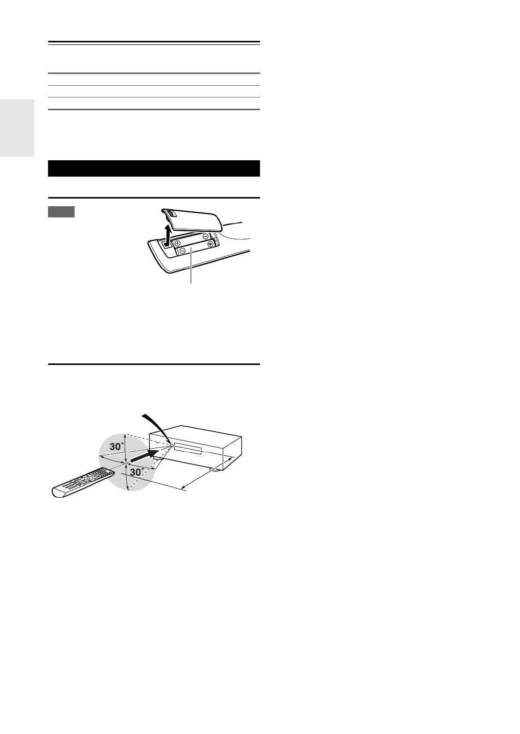
Installing the Batteries
Note
• If the remote controller
doesn’t work reliably, try
replacing the batteries.
• Don’t mix new and old
batteries or different
types of batteries.
• If you intend not to use
the remote controller for
a long time, remove the batteries to prevent damage from leak-
age or corrosion.
• Remove expired batteries as soon as possible to prevent damage
from leakage or corrosion.
Aiming the Remote Controller
To use the remote controller, point it at the AV receiver’s
remote control sensor, as shown below.
Indoor FM antenna (➔16)
AM loop antenna (➔16)
Remote controller and two batteries (AA/R6) (➔4)
Using the Remote Controller
Batteries (AA/R6)
Remote control sensor
AV receiver
Approx. 5 m

5
En
Contents
Important Safety Instructions ......................................... 2
Precautions....................................................................... 3
Supplied Accessories ...................................................... 4
Using the Remote Controller .......................................... 4
Features ............................................................................ 6
Front & Rear Panels......................................................... 7
Front Panel..................................................................... 7
Display............................................................................ 8
Rear Panel ..................................................................... 8
Remote Controller............................................................ 9
Controlling the AV Receiver ........................................... 9
About Home Theater...................................................... 10
Speakers A and B ........................................................ 10
Enjoying Home Theater................................................ 10
Connecting the AV Receiver ......................................... 11
Connecting Your Speakers .......................................... 11
About AV Connections ................................................. 13
Connecting Components with HDMI ............................ 14
Connecting External Components................................ 15
Using the AUX INPUT jack on the front panel.............. 15
Connecting Onkyo u Components ............................ 16
Connecting Antenna ..................................................... 16
Which Connections Should I Use?............................... 17
Turning On/Off the AV Receiver ................................... 18
Turning On ................................................................... 18
Turning Off ................................................................... 18
Basic Operations............................................................ 19
Playing the Connected Component.............................. 19
Displaying Source Information ..................................... 19
Using the Music Optimizer ........................................... 19
Setting the Display Brightness ..................................... 19
Muting the AV Receiver................................................ 20
Using the Sleep Timer .................................................. 20
Using Headphones....................................................... 20
Changing the Input Display .......................................... 20
Selecting Speakers A and B......................................... 20
Listening to the Radio ................................................... 21
Using the Tuner ............................................................ 21
Presetting FM/AM Stations........................................... 22
Using RDS.................................................................... 22
Recording ....................................................................... 24
Using the Listening Modes ........................................... 25
Selecting Listening Modes ........................................... 25
About Listening Modes................................................. 25
Advanced Setup ............................................................. 28
On-screen Setup Menus...............................................28
Common Procedures in Setup Menu ........................... 28
HDMI Input ................................................................... 29
Component (Component Video Input).......................... 29
Digital Audio (Digital Audio Input)................................. 29
Sp Config (Speaker Configuration)............................... 30
Sp Distance (Speaker Distance) .................................. 30
Level Cal (Level Calibration) ........................................ 31
Audio Adjust ................................................................. 31
Name Edit..................................................................... 32
Hardware ...................................................................... 32
HDMI Setup .................................................................. 32
Using the Audio Settings ..............................................34
Digital Input Signal Formats .........................................36
Adjusting the Bass & Treble ......................................... 36
Controlling iPod ............................................................. 37
Connecting an Onkyo Dock.......................................... 37
Using the Onkyo Dock.................................................. 38
Controlling Your iPod.................................................... 39
Controlling Other Components.....................................41
Preprogrammed Remote Control Codes ......................41
Entering Remote Control Codes...................................41
Remote Control Codes for
Onkyo Components Connected via u ..................... 41
Resetting REMOTE MODE Buttons ............................. 42
Resetting the Remote Controller .................................. 42
Controlling Other Components ..................................... 42
Troubleshooting .............................................................44
Specifications ................................................................. 48
About HDMI..................................................................... 49
Using an RIHD-compatible TV, Player, or Recorder ... 50
Introduction
Connections
Turning On & Basic Operations
Advanced Operations
Controlling iPod & Other Components
Others
To reset the AV receiver to its factory defaults, turn it
on and, while holding down VCR/DVR, press
ON/STANDBY (➔44).
6
En
Features
Amplifier
• 100 Watts/Channel @ 6 ohms (IEC)
• Optimum Gain Volume Circuitry
• H.C.P.S. (High Current Power Supply) Massive High
Power Transformer
Processing
• HDMI (Ver.1.4 with Audio Return Channel, 3D), Deep-
Color, x.v.Color*, Lip Sync, DTS*1-HD Master Audio,
DTS-HD High Resolution Audio, Dolby TrueHD*2,
Dolby Digital Plus, DSD and Multi-CH PCM
• Non-Scaling Configuration
• A-Form Listening Mode Memory
• Direct Mode
• Music Optimizer*3 for Compressed Digital Music files
• 192 kHz/24-bit D/A Converters
• Powerful and Highly Accurate 32-bit Processing DSP
Connections
• 3 HDMI*4 Inputs and 1 Output
• Onkyo p for System Control
• 3 Digital Inputs (2 Optical/1 Coaxial)
• Component Video Switching (2 Inputs/1 Output)
• Universal Port for the Dock for iPod*/DAB+ tuner mod-
ule
Miscellaneous
• 40 FM/AM Presets
• EX.BASS for natural deeper bass
• Crossover Adjustment
(40/50/60/80/100/120/150/200 Hz)
• A/V Sync Control Function (up to 100 ms)
• On-Screen Display via HDMI
*1
Manufactured under license under U.S. Patent #’s: 5,451,942;
5,956,674; 5,974,380; 5,978,762; 6,226,616; 6,487,535;
7,212,872; 7,333,929; 7,392,195; 7,272,567 & other U.S. and
worldwide patents issued & pending. DTS is a registered
trademark and the DTS logos, Symbol are trademarks of DTS,
Inc.
© 1996-2008 DTS, Inc. All Rights Reserved.
*2
Manufactured under license from Dolby Laboratories.
“Dolby”, “Pro Logic” and the double-D symbol are trade-
marks of Dolby Laboratories.
*3 Music Optimizer™ is a trademark of Onkyo Corporation.
*4
“HDMI, the HDMI Logo, and High-Definition Multimedia
Interface are trademarks or registered trademarks of HDMI
Licensing LLC in the United States and other countries.”
*Apple and iPod are trademarks of Apple Inc., registered in the
U.S. and other countries.
*“x.v.Color” is a trademark of Sony Corporation.

7
En
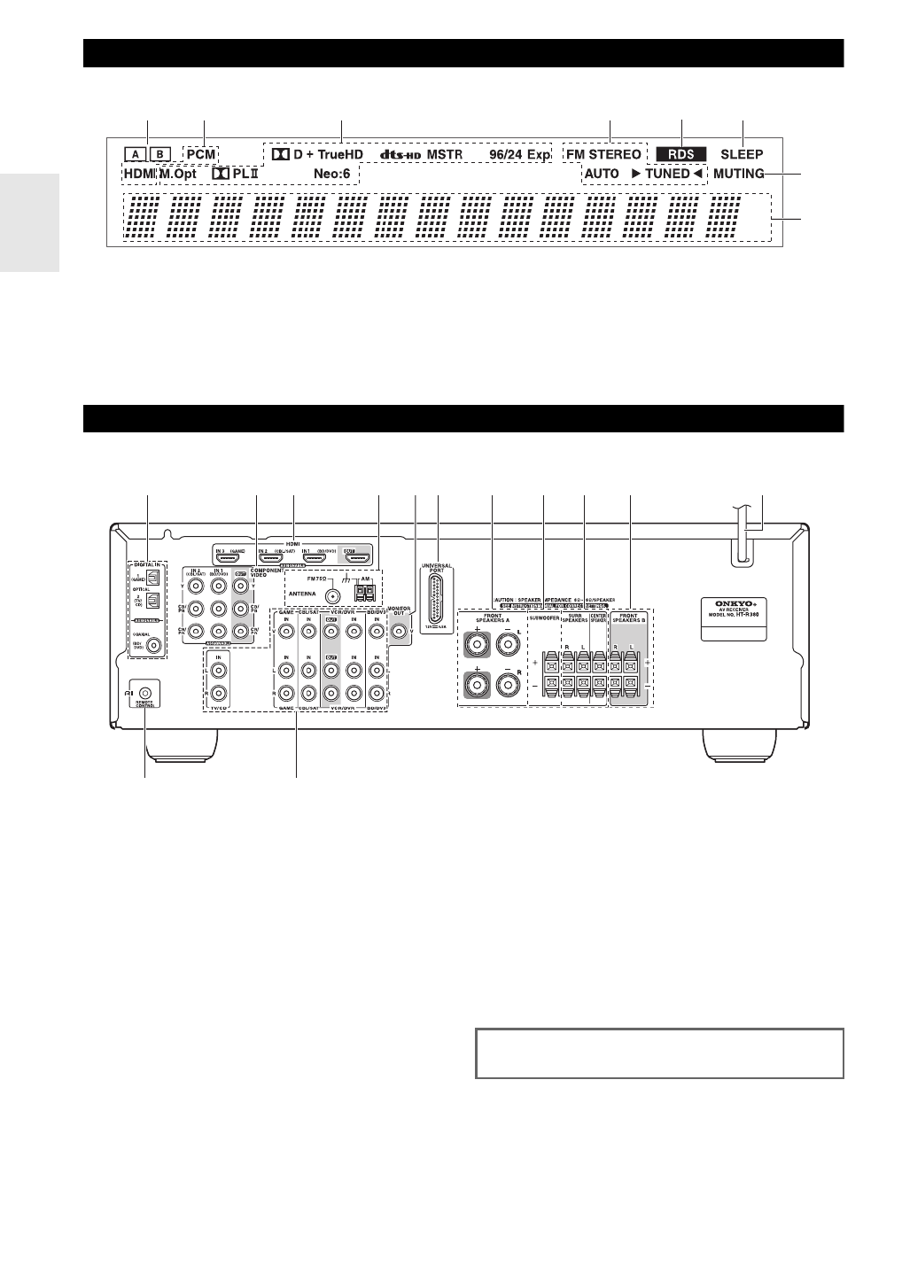
Front & Rear Panels
The actual front panel has various logos printed on it. They are not shown here for clarity.
The page numbers in parentheses show where you can find the main explanation for each item.
a ON/STANDBY button (➔18)
b STANDBY indicator (➔18)
c HDMI THRU indicator (➔33)
d SPEAKERS , )A and B buttons (➔10 20
e Remote control sensor (➔4)
f TONE LEVEL and TONE buttons (➔36)
g Display (➔8)
h LISTENING MODE buttons (➔25)
i RT/PTY/TP button (➔22)
j MEMORY button (➔22)
k TUNING MODE button (➔21)
l DISPLAY button (➔19)
m SETUP button (➔28)
n TUNING PRESET, (➔21 to 22), arrow and
ENTER buttons
o RETURN button
p MASTER VOLUME control (➔19)
q MUSIC OPTIMIZER button (➔19 35, )
r PHONES jack (➔20)
s Input selector buttons (➔19)
t AUX INPUT LINE IN jack (➔15)
Front Panel
a
s t
b c d e f hg i j kl m n o p
rq
8
En
For detailed information, see the pages in parentheses.
a A and B speaker indicators (➔10, 20)
b Audio input indicators
c Listening mode and format indicators (➔19 25, )
d Tuning indicators (➔21)
e RDS indicator (➔22)
f SLEEP indicator (➔20)
g MUTING indicator (➔20)
h Message area
a DIGITAL IN COAXIAL and OPTICAL jacks
b COMPONENT VIDEO IN and OUT jacks
c HDMI IN and OUT jacks
d FM ANTENNA jack and AM ANTENNA terminal
e MONITOR OUT V jack
f UNIVERSAL PORT jack
g FRONT SPEAKERS A terminals
h SUBWOOFER terminals
i SPEAKERS terminals
( )SURR, CENTER
j FRONT SPEAKERS B terminals
k Power cord
l u REMOTE CONTROL jack
m Composite video and analog audio jacks
(BD/DVD IN, VCR/DVR IN and OUT, CBL/SAT IN,
GAME IN, TV/CD IN)
Display
b ca e f
h
g
d
Rear Panel
a b c d kef g h i j
l m
See “Connecting the AV Receiver” for connection infor-
mation (➔11 to 17).

9
En
Remote Controller
For detailed information, see the pages in parentheses.
a ON/STANDBY button (➔18)
b REMOTE MODE/INPUT SELECTOR buttons
( )➔19, 41 to 42
c TONE, + – and buttons (➔36)
d SP A/B button (➔10 20, )
e Arrow q w/ /e r/ and ENTER buttons
f SETUP button (➔28)
g LISTENING MODE buttons (➔25)
h DIMMER button (➔19)
i DISPLAY button (➔19)
j MUTING button (➔20)
k VOL / )q w button (➔19
l RETURN button
m AUDIO button (➔34)
n SLEEP button (➔20)
■Controlling the tuner
To control the AV receiver’s tuner, press TUNER (or
RECEIVER).
You can select AM or FM by pressing TUNER repeatedly.
a Arrow q w/ buttons (➔21)
b D.TUN button (➔21)
c DISPLAY button (➔22)
d TUN MODE button (➔21)
e CH /+ – button (➔22)
f Number buttons (➔21)
Controlling the AV Receiver
i
k
c
e
d
l
m
n
f
b
g
h
f
d
c
a
e
b
a
j
To control the AV receiver, press RECEIVER to select
Receiver mode.
You can also use the remote controller to control
Onkyo Blu-ray Disc/DVD player, CD player, and
other components.
See “Entering Remote Control Codes” for more
details (➔41).

11
En
Connecting the AV Receiver
Speaker Configuration
The following table indicates the channels you should use
depending on the number of speakers that you have.
For 5.1-channel surround-sound playback, you need five
speakers and a subwoofer.
No matter how many speakers you use, a subwoofer is rec-
ommended for a really powerful and solid bass.
To get the best from your surround sound system, you
need to set the speaker settings. You can do this manually
(➔30).
Connecting the Speaker Cables
The AV receiver’s positive (+) speaker terminals are color-
coded for ease of identification. (The negative (–) speaker
terminals are all black.)
Speaker Connection Precautions
Read the following before connecting your speakers:
• You can connect speakers with an impedance of between
6 and 16 ohms. If you use speakers with a lower imped-
ance, and use the amplifier at high volume levels for a
long period of time, the built-in amp protection circuit
may be activated.
• Disconnect the power cord from the wall outlet before
making any connections.
• Read the instructions supplied with your speakers.
• Pay close attention to speaker wiring polarity. In other
words, connect positive (+) terminals only to positive (+)
terminals, and negative (–) terminals only to negative (–)
terminals. If you get them the wrong way around, the
sound will be out of phase and will sound unnatural.
• Unnecessarily long, or very thin speaker cables may
affect the sound quality and should be avoided.
• Be careful not to short the positive and negative wires.
Doing so may damage the AV receiver.
• Make sure the metal core of the wire does not have con-
tact with the AV receiver’s rear panel. Doing so may
damage the AV receiver.
• Don’t connect more than one cable to each speaker ter-
minal. Doing so may damage the AV receiver.
• Don’t connect one speaker to several terminals.
Connecting Your Speakers
Number of channels 2 3 4 5
Front speakers ✔ ✔ ✔ ✔
Center speaker ✔ ✔
Surround speakers ✔ ✔
Speaker Color
Front left White
Front right Red
Center Green
Surround left Blue
Surround right Gray
Subwoofer Purple

12
En
Connecting the Speaker Cables
Screw-type speaker terminals
Push-type speaker terminals
The following illustration shows which speaker should be connected to each pair of terminals.
Strip 12 to 15 mm of insulation from the
ends of the speaker cables, and twist the
bare wires tightly, as shown.
(Supplied speaker cables are already
stripped.)
Strip 10 to 12 mm of insulation from the ends of the speaker
cables, and twist the bare wires tightly, as shown.
(Supplied speaker cables are already stripped.)
12 to 15 mm
10 to 12 mm
Red White Gray Blue Green Purple Red White
Front
left
speaker A
Surround
right
speaker
Surround
left
speaker
Center speaker
Subwoofer
Front
right
speaker A
Front
left
speaker B
Front
right
speaker B

13
En
Connected image with AV components
• Before making any AV connections, read the manuals supplied with your AV components.
• Don’t connect the power cord until you’ve completed and double-checked all AV connections.
• Push plugs in all the way to make good connections (loose connections can cause noise or malfunc-
tions).
• To prevent interference, keep audio and video cables away from power cords and speaker cables.
AV Cables and Jacks
*Available sampling rate for PCM input signal is 32/44.1/48/88.2/96 kHz. Even 176.4/192 kHz is effective in case of the HDMI con-
nection.
Note
• The AV receiver does not support SCART plugs.
• The AV receiver’s optical digital jacks have shutter-type covers that open when an optical plug is inserted and close when it’s removed.
Push plugs in all the way.
Caution
• To prevent shutter damage, hold the optical plug straight when inserting and removing.
About AV Connections
Signal Cable Jack Description
Video and
Audio
HDMI HDMI connections can carry digital video and audio. The
AV receiver is compliant with HDMI.
Video Component video Component video separates the luminance (Y) and color
difference signals (PR B, P ), providing the best picture qual-
ity (some TV manufacturers label their component video
sockets slightly differently).
Composite video Composite video is commonly used on TVs, VCRs, and
other video equipment.
Audio Optical digital
audio
Optical digital connections allow you to enjoy digital
sound such as PCM* or Dolby Digital. The audio quality is
the same as coaxial.
Coaxial digital
audio
Coaxial digital connections allow you to enjoy digital
sound such as PCM* or Dolby Digital. The audio quality is
the same as optical.
Analog audio
(RCA)
Analog audio connections (RCA) carry analog audio.
3.5 mm Stereo
mini plug
This cable carries analog audio.
HDMI cable Other cables
: Video & Audio : Video
: Audio
Game console
Blu-ray Disc/
DVD player
TV, projector, etc. Game console
Blu-ray Disc/
DVD player
TV, projector, etc.
AV receiverAV receiver
Right!
Wrong!
HDMI
Y
PB B/C
P /CR R
Green
Blue
Red
V
Yellow
OPTICAL
Orange
L
R
White
Red
14
En
Connect your components to the appropriate jacks. The default input assignments are shown below.
✔: Assignment can be changed (➔29).
Refer to “About HDMI” (➔49) and “Using an RIHD-compatible TV, Player, or Recorder” (➔50).
Tip
To listen to audio received by the HDMI IN jacks through your TV’s speakers:
• Set the “TV Control” setting to “On” (➔34) for an p-compatible TV.
• Set the “Audio TV OUT” setting to “On” (➔32) when the TV is not compatible with p or the “TV Control” setting to “Off”.
• Set your Blu-ray Disc/DVD player’s HDMI audio output setting to PCM.
• To listen to TV audio through the AV receiver, see “Connecting External Components” (➔15).
Note
• When listening to an HDMI component through the AV receiver, set the HDMI component so that its video can be seen on the TV
screen (on the TV, select the input of the HDMI component connected to the AV receiver). If the TV power is off or the TV is set to
another input source, this may result in no sound from the AV receiver or the sound may be cut off.
• When the “Audio TV OUT” setting is set to “On” (➔32) to hear from your TV’s speakers, by controlling the AV receiver’s volume,
the sound will be output from the AV receiver’s speakers, too. When the
“TV Control” setting is set to “ ”On (➔34) to hear from
speakers of p-compatible TV, by controlling the AV receiver’s volume, the AV receiver’s speakers will produce sound while the
TV’s speakers are muted. To stop the AV receiver’s speakers producing sound, change the settings, change your TV’s settings, or turn
down the AV receiver’s volume.
■Audio return channel (ARC) function
Audio return channel (ARC) function enables an HDMI capable TV to send the audio stream to the of the HDMI OUT
AV receiver. To use this function, you must select the TV/CD input selector.
• To use ARC function, you must select the TV/CD input selector, your TV must support ARC function and “HDMI
Control” is set to “On” (➔33).
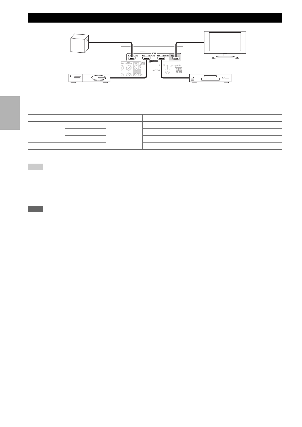
Connecting Components with HDMI
Jack Signal Components Assignable
Input HDMI IN1 Audio/Video Blu-ray Disc/DVD player ✔
HDMI IN2 Satellite, cable, set-top box, etc. ✔
HDMI IN3 Game console ✔
Output HDMI OUT TV, projector, etc.
Game console
TV, projector, etc.
Satellite, cable, set-top box, etc. Blu-ray Disc/DVD player

15
En
Connect your components to the appropriate jacks. The
default input assignments are shown below.
✔: Assignment can be changed (➔29).
■How to record the video
With the connections described here, you cannot record
the video through the AV receiver. To make a connection
for video recording (➔24).
*1 If your turntable has a moving coil (MC) type cartridge, you’ll need a commercially available MC head amp or MC transformer. See
your turntable’s manual for details.
You can also use a phono equalizer to connect a turntable with an MC-type cartridge. See your phono equalizer’s manual for details.
• With connection B, you can enjoy Dolby Digital and DTS.
• If your Blu-ray Disc/DVD player has both the main stereo and multichannel outputs, be sure to connect the main stereo
output using connection C.
Connecting External Components
The on-screen setup menus appear only on a TV that is connected to the HDMI OUT. If your TV is connected to
the MONITOR OUT V or the COMPONENT VIDEO OUT, use the AV receiver’s display when changing settings.
B A C D
No. Jack Signal Components Assignable
ACOMPONENT
VIDEO
IN 1 (BD/DVD) Component
video
Blu-ray Disc/DVD player ✔
IN 2 (CBL/SAT) Satellite, cable, set-top box, etc. ✔
OUT TV, projector, etc.
BDIGITAL IN OPTICAL IN 1 (GAME) Digital audio Game console ✔
IN 2 (TV/CD) TV, CD player ✔
COAXIAL (BD/DVD) Blu-ray Disc/DVD player ✔
CMONITOR OUT Composite
video
TV, projector, etc.
BD/DVD IN Analog audio
and composite
video
Blu-ray Disc/DVD player
VCR/DVR IN VCR or DVD recorder/Digital
Video Recorder
CBL/SAT IN Satellite, cable, set-top box, etc.
GAME IN Game console
TV/CD IN Analog audio TV, CD player, Turntable
*1,
Cassette tape deck, MD, CD-R
DUNIVERSAL PORT Analog audio/
Video
Universal port optional dock
(UP-A1 etc.)
Using the AUX INPUT jack on the front panel
Portable audio player
Analog audio line
output (➔13)
16
En
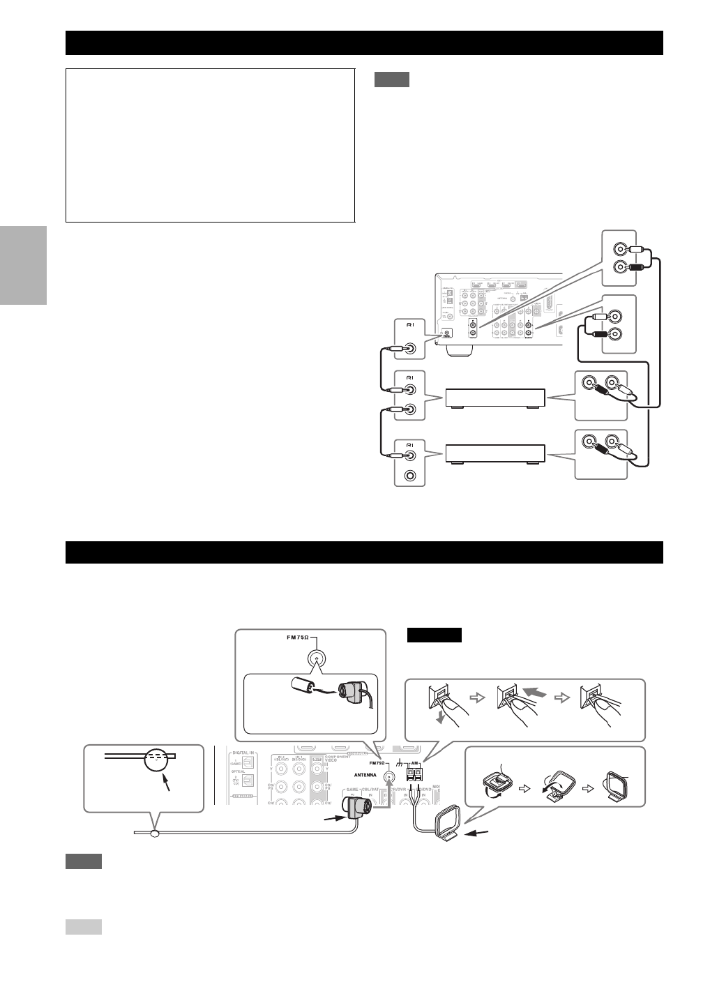
With u (Remote Interactive), you can use the following
special functions:
■System On/Auto Power On
When you start playback on a component connected via
u, if the AV receiver is on Standby, it will automati-
cally turn on and select that component as the input
source.
■Direct Change
When playback is started on a component connected via
u, the AV receiver automatically selects that compo-
nent as the input source.
■Remote Control
You can use the AV receiver’s remote controller to con-
trol your other u-capable Onkyo components, point-
ing the remote controller at the AV receiver’s remote
control sensor instead of the component. You must enter
the appropriate remote control code first (➔41).
Note
• Use only u cables for u connections. u cables are supplied
with Onkyo players (DVD, CD, etc.).
• Some components have two u jacks. You can connect either
one to the AV receiver. The other jack is for connecting addi-
tional u-capable components.
• Connect only Onkyo components to u jacks. Connecting other
manufacturer’s components may cause a malfunction.
• Some components may not support all u functions. Refer to
the manuals supplied with your other Onkyo components.
This section explains how to connect the supplied indoor FM antenna and AM loop antenna.
The AV receiver won’t pick up any radio signals without any antenna connected, so you must connect the antenna to use
the tuner.
Note
• Once your AV receiver is ready for use, you’ll need to tune into a radio station and position the antenna to achieve the best possible
reception.
• Keep the AM loop antenna as far away as possible from your AV receiver, TV, speaker cables, and power cords.
Tip
• If you cannot achieve good reception with the supplied indoor FM antenna, try a commercially available outdoor FM antenna instead.
• If you cannot achieve good reception with the supplied indoor AM loop antenna, try using it with a commercially available outdoor AM
antenna.
Connecting Onkyo u Components
Step 1:
Make sure that each Onkyo component is connected
with an analog audio cable (connection C in the hookup
examples) (➔15).
Step 2:
Make the u connection (see illustration below).
Step 3:
If you’re using an RI Dock, or cassette tape deck,
change the Input Display (➔20).
LR
IN
BD/DVD
L
R
IN
TV/CD
L
R
REMOTE
CONTROL
ANALOG
AUDIO OUT
LR
ANALOG
AUDIO OUT
e.g., CD player
e.g., DVD player
Connecting Antenna
Thumbtacks, etc.
Insert the plug fully
into the jack.
Push. Insert wire. Release.
Assembling the AM loop antenna
Indoor FM antenna (supplied) AM loop antenna (supplied)
Caution
• Be careful that you don’t injure yourself when
using thumbtacks.
17
En
The AV receiver supports several connection formats for compatibility with a wide range of AV equipment. The format
you choose will depend on the formats supported by your components. Use the following sections as a guide.
Note
The on-screen setup menus are displayed when:
• There is no video input, or
• The video input is 480p, 576p, 720p, 1080i, or 1080p.
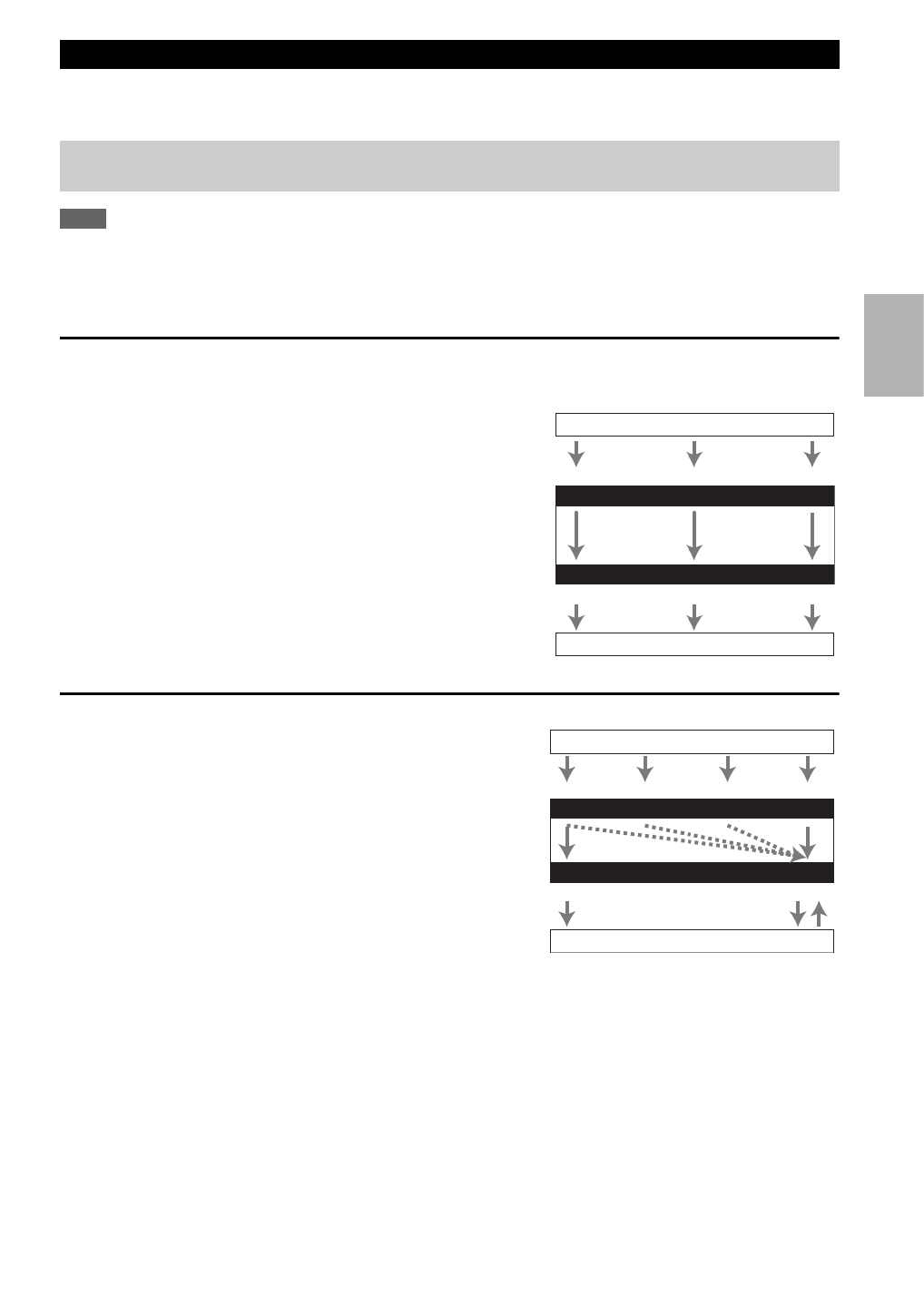
Video Connection Formats
Video component can be connected by using any one of the following video connection formats: composite video, com-
ponent video, or HDMI, the latter offering the best picture quality.
When choosing a connection format, bear in mind that the
AV receiver doesn’t convert between formats, so only outputs
of the same format as the input will output the signal.
Audio Connection Formats
Audio component can be connected by using any of the
following audio connection formats: analog, optical, coax-
ial, or HDMI.
When choosing a connection format, bear in mind that the
AV receiver does not convert digital input signals for ana-
log line outputs and vice versa. For example, audio signals
connected to an optical or coaxial digital input are not out-
put by the analog VCR/DVR OUT.
If signals are present at more than one input, the inputs
will be selected automatically in the following order of pri-
ority: HDMI, digital, analog.
Which Connections Should I Use?
The on-screen setup menus appear only on a TV that is connected to the HDMI OUT. If your TV is connected to
the MONITOR OUT V or the COMPONENT VIDEO OUT, use the AV receiver’s display when changing settings.
IN
MONITOR OUT
Blu-ray Disc, DVD player, etc.
AV receiver
TV, projector, etc.
Composite
Composite
Component
Component
Video Signal Flow Chart
HDMI
HDMI
IN
OUT
*1*2
*1
*1
*1
Blu-ray Disc, DVD player, etc.
AV receiver
TV, projector, etc.
HDMICoaxial Analog
Audio Signal Flow Chart
HDMI Analog
Optical
*1 Depends on the “Audio TV OUT” setting (➔32).
*2 This setting is available, when “Audio Return Ch” set-
ting is set to “Auto” (➔33), you must select the TV/CD
input selector and your TV must support ARC function.
18
En
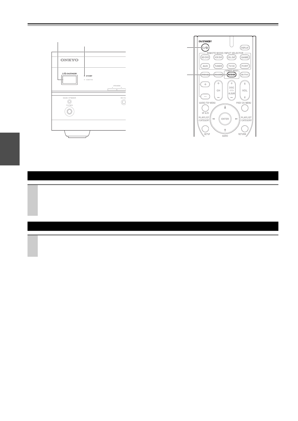
Turning On/Off the AV Receiver
Turning On
Press ON/STANDBY on the front panel.
or
Press RECEIVER followed by ON/STANDBY on the remote controller.
The AV receiver comes on, the display lights, and the STANDBY indicator goes off.
Turning Off
Press ON/STANDBY on the front panel or the remote controller.
The AV receiver will enter Standby mode. To prevent any loud surprises when you turn on the AV receiver, always
turn down the volume before you turn it off.
ON/STANDBY
ON/STANDBY
RECEIVER
STANDBY indicator
Front panel Remote controller

19
En
Basic Operations
■Operating on the AV receiver
■Operating with the remote controller
You can display various information about the current
input source as follows.
Tip
• Alternatively, you can use the AV receiver’s DISPLAY.
The following information can typically be displayed.
*1 When AM or FM radio is used, the band, preset number, and
frequency are displayed.
*2 If the input signal is analog, no format information is dis-
played. If the input signal is PCM, the sampling frequency is
displayed. If the input signal is digital but not PCM, the signal
format is displayed.
Information is displayed for about three seconds, then the pre-
viously displayed information reappears.
*3 The input source is displayed with the default name even
when you have selected a name in “Name Edit” (➔32).
The Music Optimizer function enhances the sound quality
of compressed music files.
Tip
• Alternatively, you can use the remote controller’s AUDIO and
arrow buttons.
• See “Music Optimizer” for more details (➔35).
You can adjust the brightness of the AV receiver’s display.
This manual describes the procedure using the
remote controller unless otherwise specified.
Playing the Connected Component
1
Use the input selector buttons to select the input
source.
2
Start playback on the source component.
See also:
• “Controlling Other Components” (➔41)
• “Controlling iPod” (➔37)
• “Listening to the Radio” (➔21)
3
To adjust the volume, use the MASTER VOLUME
control.
4
Select a listening mode and enjoy!
See also:
• “Using the Listening Modes” (➔25)
1
Press RECEIVER followed by INPUT SELEC-
TOR.
2
Start playback on the source component.
See also:
• “Controlling Other Components” (➔41)
• “Controlling iPod” (➔37)
• “Listening to the Radio” (➔21)
3
To adjust the volume, use VOL / .q w
4
Select a listening mode and enjoy!
See also:
• “Using the Listening Modes” (➔25)
Displaying Source Information
Press RECEIVER followed by DISPLAY repeat-
edly to cycle through the available information.
Using the Music Optimizer
Press MUSIC OPTIMIZER on the front panel.
The M.Opt indicator lights on the display.
Setting the Display Brightness
Press RECEIVER followed by DIMMER repeat-
edly to select: dim, dimmer, or normal brightness.
Input source &
volume*1
Signal format*2
or sampling fre-
quency
Input source &
listening mode*3

20
En
You can temporarily mute the output of the AV receiver.
Tip
• To unmute, press MUTING again or adjust the volume.
• The Mute function is cancelled when the AV receiver is set to
Standby.
With the sleep timer, you can set the AV receiver to turn
off automatically after a specified period.
Tip
• If you need to cancel the sleep timer, press SLEEP repeatedly
until the SLEEP indicator goes off.
• To check the time remaining until the AV receiver sleeps, press
SLEEP. Note that if you press SLEEP while the sleep time is
being displayed, you’ll shorten the sleep time by 10 minutes.
Note
• Always turn down the volume before connecting your head-
phones.
• While the headphones plug is inserted in the PHONES jack, the
speakers are turned off.
• When you connect a pair of headphones, the listening mode is
set to Stereo, unless it’s already set to Stereo, Mono, or Direct.
• The listening modes cannot be selected while a pair of head-
phones is connected.
When you connect an u-capable Onkyo component, you
must configure the input display so that u can work
properly.
This setting can be done only from the front panel.
Note
• DOCK can be selected for the TV/CD, GAME or VCR/DVR
input selector, but not at the same time.
• Enter the appropriate remote control code before using the
remote controller for the first time (➔41).
You can use two sets of front speakers with the AV
receiver: Speakers A for up to 5.1-channel playback in
your main listening room and Speakers B for 2-channel
stereo playback in another room.
Note
• While Speakers B is on, channels are reduced to 2.1 in the main
room (➔10).
Tip
• Alternatively, you can use the AV receiver’s SPEAKERS A and
B.
Muting the AV Receiver
Press RECEIVER followed by MUTING.
The output is muted and the MUTING indicator
flashes on the display.
Using the Sleep Timer
Press RECEIVER followed by SLEEP repeatedly
to select the required sleep time.
The sleep time can be set from 90 to 10 minutes in
10 minute steps.
The SLEEP indicator lights on the display when the
sleep timer has been set. The specified sleep time
appears on the display for about five seconds, then
the previous display reappears.
Using Headphones
Connect a pair of stereo headphones with a stan-
dard plug (6.3 mm) to the PHONES jack.
Changing the Input Display
1
Press TV/CD, GAME or VCR/DVR on the front
panel so that “TV/CD”, “GAME” or “VCR/DVR”
appears on the display.
2
Press and hold down TV/CD, GAME or VCR/DVR
(about 3 seconds) to change the input display.
Repeat this step to select “MD”, “CDR”, “DOCK”
or “TAPE”.
For the TV/CD input selector, the input display
changes in this order:
For the GAME input selector, the setting changes in
this order:
For the VCR/DVR input selector, the setting
changes in this order:
Selecting Speakers A and B
Press RECEIVER followed by SP A/B repeatedly
to cycle through the selection:
A B or , or both indicators light on the display.
TV/CD → MD → CDR
DOCK
→
→
TAPE
→
GAME ↔ DOCK
VCR/DVR ↔ DOCK
Speakers A → Speakers A&B → Speakers B
→
Off ←
21
En
Listening to the Radio
With the built-in tuner you can enjoy AM and FM radio
stations. You can store your favorite stations as presets for
quick selection.
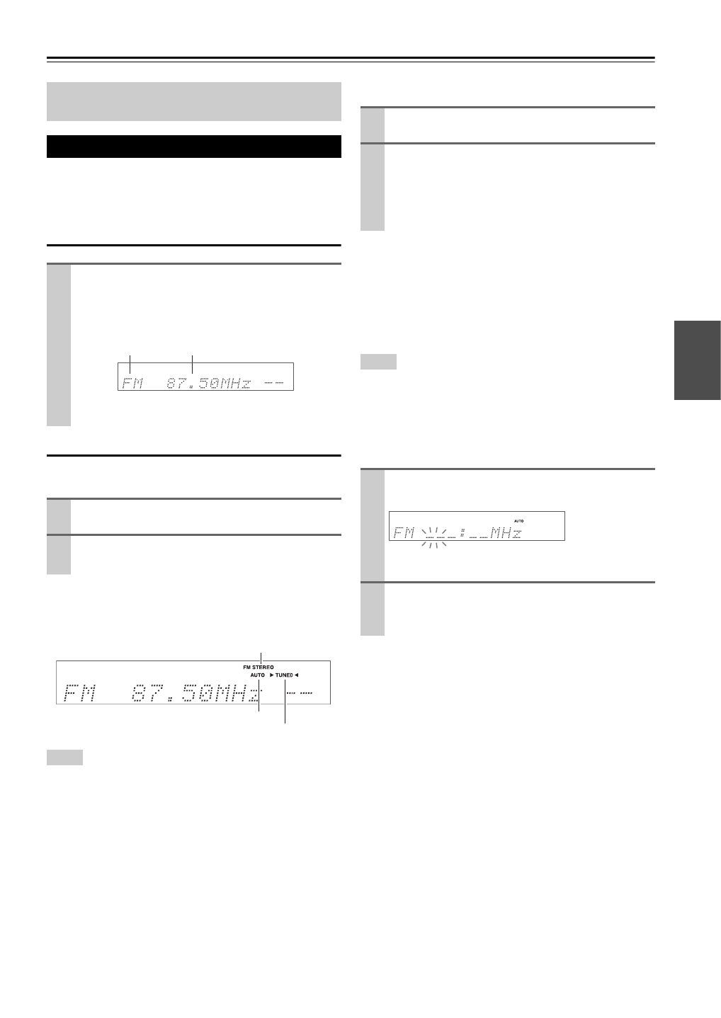
Listening to the Radio
Tuning into Radio Stations
■Auto tuning mode
When tuned into a station, the TUNED indicator lights.
When tuned into a stereo FM station, the FM STEREO
indicator lights on the display, as shown.
Tip
• Alternatively, you can use the remote controller’s TUN MODE
and arrow buttons.
■Manual tuning mode
This model changes AM frequency in 9 or 10 kHz steps.
In manual tuning mode, FM stations will be in mono.
Tuning into weak FM stereo stations
If the signal from a stereo FM station is weak, it may be
impossible to get good reception. In this case, switch to
manual tuning mode and listen to the station in mono.
Tip
• Alternatively, you can use the remote controller’s TUN MODE
and arrow buttons.
■Tuning into stations by frequency
You can tune into AM and FM stations directly by enter-
ing the appropriate frequency.
This section describes the procedure using the but-
tons on the front panel unless otherwise specified.
Using the Tuner
Press TUNER to select either “AM” or “FM”.
In this example, FM has been selected.
Each time you press TUNER, the radio band
changes between AM and FM.
(Actual display depends on the country.)
1
Press TUNING MODE so that the AUTO indicator
lights on the display.
2
Press TUNING / .q w
Searching stops when a station is found.
Band Frequency
FM STEREO
AUTO
TUNED
1
Press TUNING MODE so that the AUTO indicator
goes off on the display.
2
Press and hold TUNING / .q w
The frequency stops changing when you release the
button.
Press the buttons repeatedly to change the frequency
one step at a time.
1
On the remote controller, press TUNER repeat-
edly to select “AM” or “FM”, followed by D.TUN.
(Actual display depends on the country.)
2
Within 8 seconds, use the number buttons to enter
the frequency of the radio station.
For example, to tune to 87.50 (FM), press 8, 7, 5, 0.
23
En
Finding Stations by Type (PTY)
You can search for radio stations by type.
Listening to Traffic News (TP)
You can search for stations that broadcast traffic news.
■RDS program types (PTY)
1
Press RT/PTY/TP twice.
The current program type appears on the display.
2
Use PRESET /e r to select the type of program
you want.
See the table shown later in this chapter.
3
To start the search, press ENTER.
The AV receiver searches until it finds a station of
the type you specified, at which point it stops briefly
before continuing with the search.
4
When a station you want to listen to is found, press
ENTER.
If no stations are found, the message “Not Found”
appears.
1
Press RT/PTY/TP three times.
If the current radio station is broadcasting TP (Traf-
fic Program), “[TP]” will appear on the display, and
traffic news will be heard as and when it’s broadcast.
If “TP” without square brackets appears, this means
that the station is not broadcasting TP.
2
To locate a station that is broadcasting TP, press
ENTER.
The AV receiver searches until it finds a station that’s
broadcasting TP.
If no stations are found, the message “Not Found”
appears.
Type Display
None None
News reports News
Current affairs Affairs
Information Info
Sport Sport
Education Educate
Drama Drama
Culture Culture
Science and technology Science
Varied Varied
Pop music Pop M
Rock music Rock M
Middle of the road music Easy M
Light classics Light M
Serious classics Classics
Other music Other M
Weather Weather
Finance Finance
Children’s programmes Children
Social affairs Social
Religion Religion
Phone in Phone In
Travel Travel
Leisure Leisure
Jazz music Jazz
Country music Country
National music Nation M
Oldies music Oldies
Folk music Folk M
Documentary Document
Alarm test TEST
Alarm Alarm!

24
En
Recording
This section explains how to record the selected input source to a component with recording capability, and how to record
audio and video from different sources.
Connecting a Recording Component
Note
• The AV receiver must be turned on for recording. Recording is
not possible while it’s in Standby mode.
• If you want to record directly from your TV or playback VCR to
the recording VCR without going through the AV receiver, con-
nect the TV/VCR’s audio and video outputs directly to the
recording VCR’s audio and video inputs. See the manuals sup-
plied with your TV and VCR for details.
• Video signals connected to composite video inputs can be
recorded only via composite video outputs. If your TV/VCR is
connected to a composite video input, the recording VCR must
be connected to a composite video output.
• The surround sound and DSP listening modes cannot be
recorded.
• Copy-protected Blu-ray discs and DVDs cannot be recorded.
• Sources connected to a digital input cannot be recorded. Only
analog inputs can be recorded.
• DTS signals will be recorded as noise, so don’t attempt analog
recording of DTS CDs or LDs.
AV Recording
Audio sources can be recorded to a recorder (e.g., cassette
deck, CDR, MD) connected to the VCR/DVR OUT jacks.
Video sources can be recorded to a video recorder (e.g.,
VCR, DVD recorder) connected to the VCR/DVR OUT
jack.
Recording Separate AV Sources
Here you can record audio and video from completely
separate sources, allowing you to overdub audio onto your
video recordings. This function takes advantage of the fact
that when an audio-only input source (TV/CD) is selected,
the video input source remains unchanged.
In the following example, audio from the CD player con-
nected to the TV/CD IN and video from the camcorder
connected to the BD/DVD IN are recorded by the VCR
connected to the VCR/DVR OUT jacks.
1
Use the input selector buttons to select the source
that you want to record.
You can watch the source while recording. The AV
receiver’s MASTER VOLUME control has no effect
on recording.
2
On your recorder, start recording.
3
On the source component, start playback.
If you select another input source during recording,
that input source will be recorded.
AUDIO
IN
L R
VIDEO
IN
Cassette, CDR,
MD, etc.
VCR,
DVD recorder
1
Prepare the camcorder and CD player for play-
back.
2
Prepare the VCR for recording.
3
Press BD/DVD input selector.
4
Press TV/CD input selector.
This selects the CD player as the audio source, but
leaves the camcorder as the video source.
5
Start recording on the VCR and start playback on
the camcorder and CD player.
The video from the camcorder and the audio from
the CD player are recorded by the VCR.
Camcorder
VCRCD player
: Video signal
: Audio signal

26
En
■Speaker Layout
The illustration shows which speakers are activated in each channel. See “Sp Config (Speaker Configuration)” for the
speaker setup (➔30).
Listening Modes
Listening Mode Description Input
Source
Speaker
Layout
Direct In this mode, audio from the input source is output without surround-sound process-
ing. The “Sp Config” (presence of speakers), “Sp Distance” and “A/V Sync” settings
are enabled, but much of the processing set via AUDIO is disabled. See “Advanced
Setup” for more details (➔28).
A
S
D
F
ZX
C
Stereo Sound is output by the front left and right speakers and subwoofer.
Mono Use this mode when watching an old movie with a mono soundtrack, or use it with the
foreign language soundtracks recorded in the left and right channels of some movies.
It can also be used with DVDs or other sources containing multiplexed audio, such as
karaoke DVDs.
Multichannel This mode is for use with PCM multichannel sources. D XC
Dolby Pro Logic II Dolby Pro Logic II expands any 2-channel source for 5.1-channel playback. It pro-
vides a very natural and seamless surround-sound experience that fully envelops the
listener. As well as music and movies, video games can also benefit from the dramatic
spatial effects and vivid imaging.
• Dolby PLII Movie
Use this mode with DVDs and videos that bear the Dolby Surround logo or TV shows
that feature Dolby Surround. You can also use this mode with stereo movies or TV
shows and the AV receiver will create a 5.1 surround mix from the 2-channel stereo.
• Dolby PLII Music
Use this mode to add 5.1 surround to stereo sources such as music CDs and DVDs.
• Dolby PLII Game
Use this mode when playing game discs.
S XC
Dolby Digital In this mode, audio from the input source is output without surround-sound process-
ing. “Sp Config” (presence of speakers), “Crossover”, “ ”, “Sp Distance A/V Sync”
and much of the processing set via AUDIO are enabled. See “Advanced Setup” for
more details (➔28).
D
F
XC
Dolby Digital Plus*1
Dolby TrueHD
DTS D XC
DTS-HD High
Resolution Audio
D
F
XC
DTS-HD Master
Audio
DTS Express S
D
XC
Z X C
b
ac
d
a Front speakers
c Subwoofer
b Center speaker
d Surround speakers
D i r e c t
S t e r e o
M o n o
M u l t i c h
P L M o v i e
P L M u s i c
P L G a m e
D o l b y D
D o l b y D +
T er u H D
D T S
D T S – H D H R
D T S – H D MS T R
D T S E x p r e s s
Produkt Specifikationer
| Mærke: | Onkyo |
| Kategori: | Modtager |
| Model: | HT-R380 |
Har du brug for hjælp?
Hvis du har brug for hjælp til Onkyo HT-R380 stil et spørgsmål nedenfor, og andre brugere vil svare dig
Modtager Onkyo Manualer

23 November 2024
3 Oktober 2024
29 August 2024
25 August 2024
15 August 2024
11 August 2024
11 August 2024
10 August 2024
6 August 2024
4 August 2024
Modtager Manualer
- Modtager Bosch
- Modtager SilverCrest
- Modtager Denver
- Modtager Sencor
- Modtager Sony
- Modtager Fenton
- Modtager Panasonic
- Modtager Hager
- Modtager VOX
- Modtager Pro-Ject
- Modtager Anthem
- Modtager Philips
- Modtager IFM
- Modtager Musway
- Modtager Audio-Technica
- Modtager Peavey
- Modtager Pioneer
- Modtager TOA
- Modtager Hifonics
- Modtager Sharp
- Modtager Qtx
- Modtager Dynacord
- Modtager Logitech
- Modtager Behringer
- Modtager Emos
- Modtager Kenwood
- Modtager Neumann
- Modtager Sandberg
- Modtager MB Quart
- Modtager Smart
- Modtager Sennheiser
- Modtager Harman Kardon
- Modtager Garmin
- Modtager Grundig
- Modtager Motorola
- Modtager Roland
- Modtager Asus
- Modtager Golden Age Project
- Modtager Pyle
- Modtager Argon
- Modtager Roksan
- Modtager Denon
- Modtager Yamaha
- Modtager Bowers & Wilkins
- Modtager Matsui
- Modtager Scansonic
- Modtager AVM
- Modtager Nedis
- Modtager Sonoro
- Modtager Kicker
- Modtager Optoma
- Modtager Renegade
- Modtager LD Systems
- Modtager Hama
- Modtager Auna
- Modtager Thomson
- Modtager Aiwa
- Modtager Nokia
- Modtager Rega
- Modtager Yorkville
- Modtager Belkin
- Modtager Pyle Pro
- Modtager JBL
- Modtager AKAI
- Modtager Teufel
- Modtager DataVideo
- Modtager Strong
- Modtager Audio Pro
- Modtager RCF
- Modtager Optex
- Modtager Smartwares
- Modtager Chandler
- Modtager Trevi
- Modtager Trust
- Modtager Blaupunkt
- Modtager JVC
- Modtager Hilti
- Modtager Crunch
- Modtager Skytec
- Modtager Medion
- Modtager Vivanco
- Modtager Megasat
- Modtager Cambridge
- Modtager Tangent
- Modtager Cisco
- Modtager König
- Modtager Metronic
- Modtager TechniSat
- Modtager Meliconi
- Modtager Bang And Olufsen
- Modtager Bose
- Modtager Geemarc
- Modtager Jabra
- Modtager Klipsch
- Modtager Alpine
- Modtager Salus
- Modtager Triax
- Modtager Tripp Lite
- Modtager Exibel
- Modtager Mercury
- Modtager Genie
- Modtager Vaddio
- Modtager Goobay
- Modtager KEF
- Modtager Technics
- Modtager Summit Audio
- Modtager Jensen
- Modtager Alecto
- Modtager Icom
- Modtager Astro
- Modtager Plantronics
- Modtager HQ
- Modtager Krüger&Matz
- Modtager Canal Digital
- Modtager DJI
- Modtager Marmitek
- Modtager Zalman
- Modtager PreSonus
- Modtager Kopul
- Modtager Godox
- Modtager Kathrein
- Modtager Sonos
- Modtager NAD
- Modtager AJA
- Modtager Tascam
- Modtager Bogen
- Modtager Omnitronic
- Modtager Velleman
- Modtager Marshall
- Modtager Sonance
- Modtager Telestar
- Modtager Vivotek
- Modtager Zoom
- Modtager Bush
- Modtager JUNG
- Modtager Fostex
- Modtager MIPRO
- Modtager Dual
- Modtager Electro-Voice
- Modtager HQ Power
- Modtager Fredenstein
- Modtager RME
- Modtager Sagem
- Modtager Focal
- Modtager Line 6
- Modtager HK Audio
- Modtager Teac
- Modtager GlobalSat
- Modtager Imperial
- Modtager Autotek
- Modtager Magnat
- Modtager Saramonic
- Modtager Thorens
- Modtager Marantz
- Modtager ELAC
- Modtager Hartke
- Modtager McIntosh
- Modtager Hertz
- Modtager American Audio
- Modtager ART
- Modtager Bluesound
- Modtager Yaesu
- Modtager Polk
- Modtager Monacor
- Modtager Samson
- Modtager Audizio
- Modtager JL Audio
- Modtager Raymarine
- Modtager Sogo
- Modtager Rupert Neve Designs
- Modtager Jamo
- Modtager Chamberlain
- Modtager FiiO
- Modtager DBX
- Modtager Warm Audio
- Modtager Devolo
- Modtager Simrad
- Modtager Radial Engineering
- Modtager Galaxy Audio
- Modtager Renkforce
- Modtager Marshall Electronics
- Modtager Chord
- Modtager Alto
- Modtager Maxview
- Modtager Manhattan
- Modtager Aquatic AV
- Modtager Caliber
- Modtager Audiolab
- Modtager Deaf Bonce
- Modtager Music Hall
- Modtager APart
- Modtager LogiLink
- Modtager Brondi
- Modtager Kramer
- Modtager Rotel
- Modtager Metra
- Modtager QSC
- Modtager Black Lion Audio
- Modtager Naim
- Modtager Solid State Logic
- Modtager Citronic
- Modtager Thomann
- Modtager RDL
- Modtager NAV-TV
- Modtager TV Star
- Modtager Edision
- Modtager Clarion
- Modtager Sound Devices
- Modtager Wharfedale
- Modtager Universal Audio
- Modtager Valueline
- Modtager Fender
- Modtager TIC
- Modtager Vision
- Modtager Majestic
- Modtager Zgemma
- Modtager MuxLab
- Modtager Panduit
- Modtager Morel
- Modtager Cerwin-Vega
- Modtager Axis
- Modtager Mackie
- Modtager Avalon
- Modtager Wavtech
- Modtager Xantech
- Modtager Reloop
- Modtager Crest Audio
- Modtager Oculus VR
- Modtager Lindell Audio
- Modtager Audio Limited
- Modtager ATen
- Modtager Shure
- Modtager Sangean
- Modtager Vimar
- Modtager Power Dynamics
- Modtager Rockford Fosgate
- Modtager Grace Design
- Modtager Smart-AVI
- Modtager Martin Logan
- Modtager Dahua Technology
- Modtager Fosi Audio
- Modtager Terratec
- Modtager Vivolink
- Modtager Phoenix Gold
- Modtager Memphis Audio
- Modtager Vonyx
- Modtager Scosche
- Modtager Speco Technologies
- Modtager Reely
- Modtager Boss
- Modtager Ibanez
- Modtager Nexa
- Modtager Klark Teknik
- Modtager StarTech.com
- Modtager S.M.S.L
- Modtager FBT
- Modtager InLine
- Modtager Focusrite
- Modtager Blackstar
- Modtager Crestron
- Modtager DAP-Audio
- Modtager Revel
- Modtager SPL
- Modtager Ground Zero
- Modtager Vincent
- Modtager Lindy
- Modtager GoGen
- Modtager Kogan
- Modtager Arcam
- Modtager Russound
- Modtager Audison
- Modtager Crown
- Modtager AVMATRIX
- Modtager Kanto
- Modtager Lumantek
- Modtager Elektrobock
- Modtager Rolls
- Modtager Cyrus
- Modtager Fusion
- Modtager Definitive Technology
- Modtager Kemo
- Modtager Delta Dore
- Modtager Insignia
- Modtager Adastra
- Modtager Lectrosonics
- Modtager Audac
- Modtager JETI
- Modtager Konig & Meyer
- Modtager FSR
- Modtager CYP
- Modtager Atlas Sound
- Modtager AKG
- Modtager AEA
- Modtager DiO
- Modtager AMX
- Modtager Homematic IP
- Modtager MXL
- Modtager August
- Modtager Xoro
- Modtager AudioControl
- Modtager Mooer
- Modtager Audiotec Fischer
- Modtager Bugera
- Modtager Audix
- Modtager Ibiza Sound
- Modtager Steren
- Modtager Ocean Matrix
- Modtager Comprehensive
- Modtager Orava
- Modtager Intelix
- Modtager Match
- Modtager Alfatron
- Modtager HiFi ROSE
- Modtager Classé
- Modtager Audioengine
- Modtager Musical Fidelity
- Modtager Advance Acoustic
- Modtager NuPrime
- Modtager REL Acoustics
- Modtager Artsound
- Modtager BZBGear
- Modtager Key Digital
- Modtager Ram Audio
- Modtager KanexPro
- Modtager Sonifex
- Modtager Gefen
- Modtager Cranborne Audio
- Modtager TV One
- Modtager Whirlwind
- Modtager Apantac
- Modtager Ferguson
- Modtager SRS
- Modtager Inovonics
- Modtager Blustream
- Modtager C2G
- Modtager WyreStorm
- Modtager Advance
- Modtager IFi Audio
- Modtager Cabasse
- Modtager DLS
- Modtager Ampeg
- Modtager Amplicom
- Modtager Amiko
- Modtager Hirschmann
- Modtager Palsonic
- Modtager Stinger
- Modtager Brigmton
- Modtager Sunstech
- Modtager Redline
- Modtager Marquant
- Modtager Matrox
- Modtager Mac Audio
- Modtager Denson
- Modtager Valcom
- Modtager Rocketfish
- Modtager Naxa
- Modtager Sherwood
- Modtager Conrad
- Modtager Zehnder
- Modtager Mx Onda
- Modtager Swissonic
- Modtager Pure Acoustics
- Modtager Iriver
- Modtager Lanzar
- Modtager Humax
- Modtager Pinnacle
- Modtager Graupner
- Modtager BOYA
- Modtager Integra
- Modtager Revox
- Modtager Comica
- Modtager Audient
- Modtager Hegel
- Modtager PAC
- Modtager Luxman
- Modtager Infinity
- Modtager Linn
- Modtager Monitor Audio
- Modtager Monoprice
- Modtager Aplic
- Modtager Axton
- Modtager Proel
- Modtager DB Technologies
- Modtager Neets
- Modtager OSD Audio
- Modtager Mark Levinson
- Modtager Soundstream
- Modtager Block
- Modtager PSB
- Modtager Formuler
- Modtager SVS
- Modtager LTC
- Modtager JB Systems
- Modtager Dreambox
- Modtager James
- Modtager HUMANTECHNIK
- Modtager SIIG
- Modtager PSSO
- Modtager Primare
- Modtager Kali Audio
- Modtager Wet Sounds
- Modtager Televés
- Modtager MTX Audio
- Modtager Astell&Kern
- Modtager Hughes & Kettner
- Modtager Manley
- Modtager MEE Audio
- Modtager Extron
- Modtager PureLink
- Modtager Ashly
- Modtager HEOS
- Modtager Legamaster
- Modtager Benchmark
- Modtager Madison
- Modtager Leviton
- Modtager Ebode
- Modtager Medeli
- Modtager Nubert
- Modtager Palmer
- Modtager Vocopro
- Modtager Phonocar
- Modtager Xtrend
- Modtager Helix
- Modtager Winegard
- Modtager Laney
- Modtager Devialet
- Modtager Xsarius
- Modtager EA
- Modtager DirecTV
- Modtager Octagon
- Modtager GOgroove
- Modtager Avantree
- Modtager LYYT
- Modtager Antelope Audio
- Modtager CE Labs
- Modtager Pharos
- Modtager Accell
- Modtager Jolida
- Modtager Intertechno
- Modtager Shanling
- Modtager GigaBlue
- Modtager Black Hydra
- Modtager RetroSound
- Modtager Ecler
- Modtager Viscount
- Modtager Ashdown Engineering
- Modtager Synq
- Modtager Parasound
- Modtager Roswell
- Modtager Velodyne
- Modtager Epcom
- Modtager Sunfire
- Modtager Selfsat
- Modtager Skytronic
- Modtager Topp Pro
- Modtager Whistler
- Modtager ESX
- Modtager Karma
- Modtager Dimavery
- Modtager AMS Neve
- Modtager Powersoft
- Modtager LinksPoint
- Modtager Lotronic
- Modtager Esoteric
- Modtager Markbass
- Modtager IMG Stage Line
- Modtager Wireless Solution
- Modtager Aurel
- Modtager NUVO
- Modtager Phoenix Audio
- Modtager AVPro Edge
- Modtager Comtek
- Modtager Fishman
- Modtager Pyramid
- Modtager LEA
- Modtager Sound Ordnance
- Modtager Canyon
- Modtager FiveO
- Modtager Planet Audio
- Modtager SureCall
- Modtager Elipson
- Modtager Lyngdorf
- Modtager FoneStar
- Modtager Phonic
- Modtager Koda
- Modtager Atlona
- Modtager Hotone
- Modtager Trace Elliot
- Modtager Bang Olufsen
- Modtager JTS
- Modtager AER
- Modtager Dynavox
- Modtager Modelcraft
- Modtager Fontastic
- Modtager Simaudio
- Modtager Niles
- Modtager Knoll
- Modtager Aguilar
- Modtager Creek
- Modtager Mobile Crossing
- Modtager The T.amp
- Modtager DAP
- Modtager Krell
- Modtager Edwards Signaling
- Modtager ANKARO
- Modtager A-NeuVideo
- Modtager Bellari
- Modtager CAD Audio
- Modtager Polsen
- Modtager Triangle
- Modtager Lab Gruppen
- Modtager AmpliVox
- Modtager Audiofrog
- Modtager CyberData Systems
- Modtager Williams Sound
- Modtager SoundTube
- Modtager Glemm
- Modtager WesAudio
- Modtager AudioSource
- Modtager Stewart
- Modtager Leema
- Modtager Axing
- Modtager Seco-Larm
- Modtager Camille Bauer
- Modtager Mosconi
- Modtager Crest
- Modtager TechLogix Networx
- Modtager Audibax
- Modtager Meridian
- Modtager Quad
- Modtager BC Acoustique
- Modtager Gold Note
- Modtager IOTAVX
- Modtager Shinybow
- Modtager Rexing
- Modtager Inter-M
- Modtager Sinus Live
- Modtager Soundtrack
- Modtager Canor
- Modtager Unison Research
- Modtager Universal Remote Control
- Modtager BMB
- Modtager Inateck
- Modtager Cloud
- Modtager Taga Harmony
- Modtager Datapath
- Modtager Antelope
- Modtager PTN-electronics
- Modtager Clare Controls
- Modtager Loxjie
- Modtager Cayin
- Modtager Technical Pro
- Modtager VMV
- Modtager CSL
- Modtager DVDO
- Modtager Henry Engineering
- Modtager Line Magnetic
- Modtager ButtKicker
- Modtager Atoll
- Modtager SmartSystem
- Modtager Pearstone
- Modtager Streacom
Nyeste Modtager Manualer
8 April 2025
8 April 2025
8 April 2025
7 April 2025
4 April 2025
4 April 2025
4 April 2025
4 April 2025
4 April 2025
4 April 2025