Oplink IPC1200 Manual
Oplink
Overvågningskamera
IPC1200
Læs nedenfor 📖 manual på dansk for Oplink IPC1200 (27 sider) i kategorien Overvågningskamera. Denne guide var nyttig for 17 personer og blev bedømt med 4.5 stjerner i gennemsnit af 2 brugere
Side 1/27

V 2.17t1
O
Oplink Communications, Inc.
Opli
T
Us
Oplink Communications, Inc.
1
nk
Security
T
ripleShield
Hardware
ser Manual

V 2.17t1
Door
R
wi
4
1
Oplink Communications, Inc.
r/W
indow Sensor
Use on doors, windo
Siren
Siren integrated with
security technology
emote Control
th Panic Button
Arm/Disarm system
a
hotline
-port USB Hub
Additional USB ports
devices to OPU
6
G Flash Drive
Extra data storage fo
recordings
4
ws, et
.
Smart wireless
and emergency
to connect
r video

V 2.17t1
Assemble Assemble Assemble Assemble OPU SOPU SOPU SOPU S
tationtationtationtation
Oplink Communications, Inc.
n n n n
AAAAnd nd nd nd CCCConnect onnect onnect onnect TTTTo o o o RRRRouterouterouterouter
…………
Contents
A. OPU
B. Dongle
C.
Ethernet Ca
D.
Power Adap
E. 16G
Flash D
F. USB Hub
Overview Fea
•
Smart setup
•
Bridge the c
for all Oplink
•
Provide wire
control
func
Security syst
•
OPU allows
recovery
•
Transmit sen
control signa
•
Support Opl
Wireless Feat
•
Support IEEE
standards
• Wire
d and W
5
…
……..
1
ble
pter
rive
atures
p wizard
ommunication
k smart devices
eless access and
ction of mi
tem
for system
nsor data and
al
ink cloud server
tures
E 802.11 b/g/n
Wireless Network

V 2.17t1
OPU and Dongle Installation wit
a.
Plug the Dongle and the
Note: The Flash Drive
do
be powered down before
b. Plug the Hub into the
OP
c. Connect the OPU to the
d. Plug power adapter to
th
e.
Enable DHCP setup (see
*Most
routers have their DH
Oplink Communications, Inc.
Support
•
Security Sup
encryption
th USB Hub and Flash Drive
Flash Drive into the Hub.
o
es not support hot swapping n
or hot plugging.
e adding or removing
the Flash Drive to
or from
U.
home router using the provided Ethernet
cable
he
OPU and an outlet.
Appendix B for DHCP setting of router)
.
HCP setting set to “Enabled” by default.
6
pport:
WPA2-PSK
The
OPU must
m the Hub
.
e.

V 2.17t1
SetSetSetSet UUUUp Ap Ap Ap And nd nd nd Power Power Power Power UUUU
p IPp IPp IPp IP
Oplink Communications, Inc.
PPPP
CameraCameraCameraCamera
…………………..…..…..…..…
Contents
A. Camera
B. Bracket
C. Power Adapter
D. Mounting Screws And Dry Wall A
nchor
Overview Features
• Smart setup wizard
• High quality video
• Built-in antenna and microphone
• Support Oplink cloud server
• Day/night vision
•
Records automatically when alarms are
• Remote monitoring from smartphone
o
Wireless Features
• Supports IEEE 802.11 b/g/n standards
• Wired and Wireless Network Support
• Security Support: WPA2-
PSK encryption
7
..….....
2
r
s
triggered
or
tablet
n

V 2.17t1
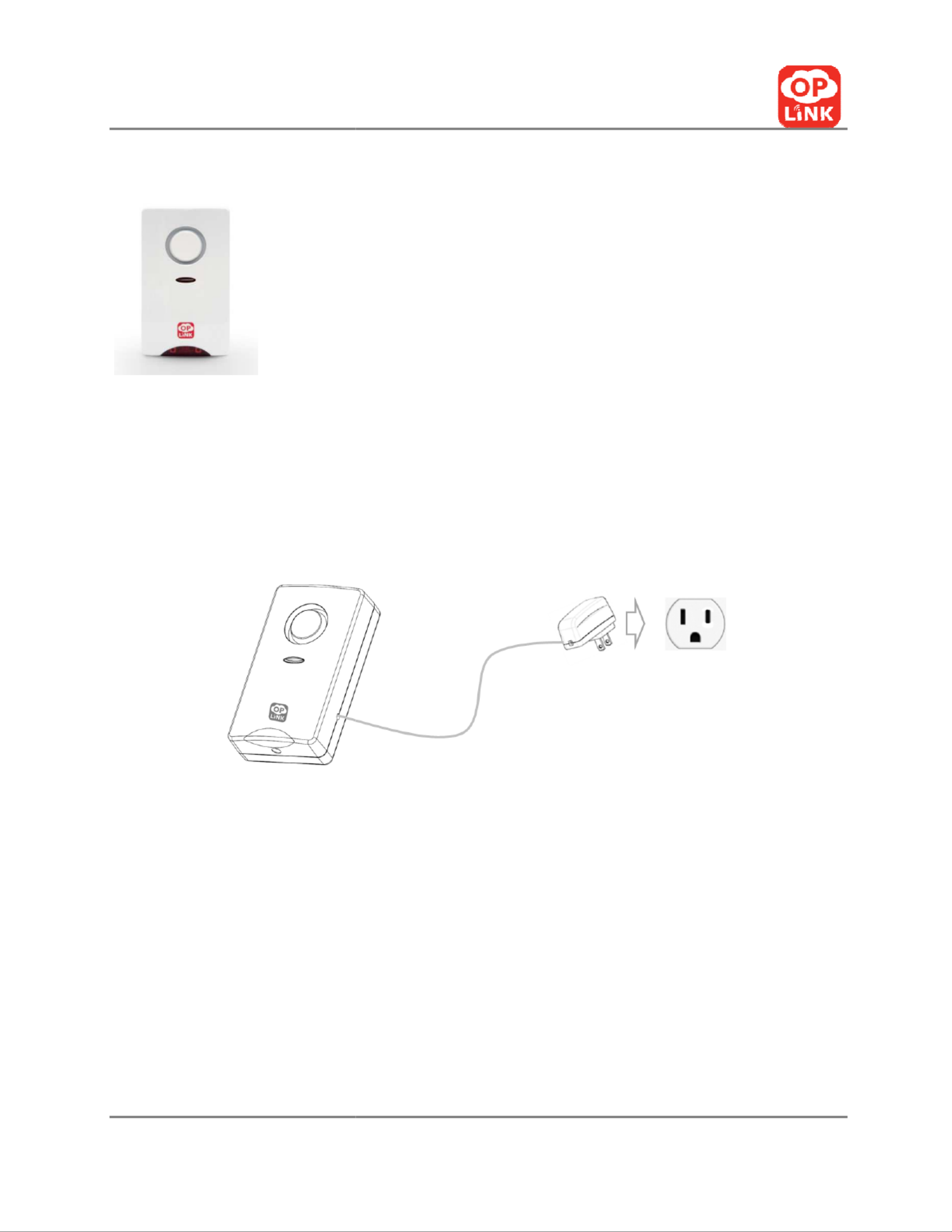
Set Up the Camera
a.
Place the camera within
b.
Connect power adapter t
Mounting the Camera (Opt
Note:
The camera can also be pl
you
placing the camera on a cou
it easy to monitor at night.
Step 1: Install
camera attachme
a.
At the desired camera mo
using the provided screws.
b. Make use of the
provided
Oplink Communications, Inc.
Camera Installation
range of a power outlet and co
nnect power cor
to the camera
.
ional)
aced on a table using the bracket provided.
We
nter
top giving it a clear line of sight. Infrared ni
nt base
unting location, secure the camera attachment
screw anchors if necessary.
8
rd to the outlet.
e recommend
ght vision makes
t base to the wall

V 2.17t1
Step 2: Mount the camera
a. Screw camera onto atta
ch
b. Secure camera using attac
Step 3: Complete the camera’s m
a. Make sure the camera is f
b. Adjust the camera to the p
Oplink Communications, Inc.
hment base
.
chment base nut.
mount
firmly fixed on the wall.
preferred position.
9
V 2.17t1
O
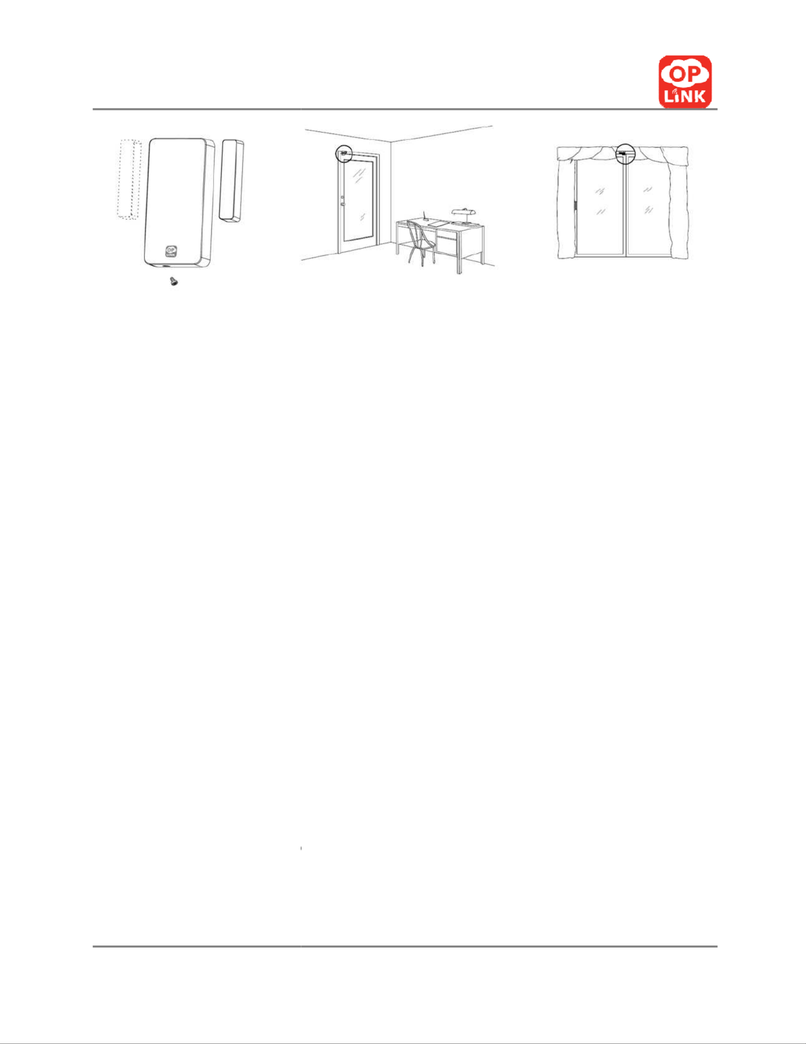
To install the sensors:
1. Install the batteries.
2. Attach the double-
sided t
3. Door/Window:
a. On your door:
i.
After selec
away from
the immov
ii. Place the
s
unit aligne
quarter of
b. On your window:
i.
After selec
should be
ii.
Place the s
each unit a
or a quart
4.
When you open and close
opened
and then come b
Oplink Communications, Inc.
Sensor DWM1300 Installation
tape onto the backs of the units
.
cting a location on the door, preferably on the e
m the hinges, the large unit of the sensor should
vable frame of the door.
small unit on the movable door
with the small a
ed and not exceeding the recommended width o
f an inch between the sensors for best performa
cting a location on the window,
the large unit of
placed on the immovable window frame.
small unit on the movable window with the sma
aligned and not exceeding the recommended w
er of an inch between the sens
ors for best perfo
e the doors and windows, the two parts should
back
together when closed.
11
edge of the door
be placed on
arrows on each
of a pencil or a
ance.
f the sensor
all arrows on
width of a pencil
ormance.
separate when

V 2.17t1
O
*Note: If your door
or window d
sensor on the frame, it is
accept
make the placing easier
. This is
should only be used
when neces
Warning:
Do not dispose of electrical
appl
facilities.
Contact your local gove
available.
Oplink Communications, Inc.
do
es not allow you to properly place the large
u
table
to place the smaller unit of the sensor o
n
an acceptable approach to sens
or
placement,
ssary.
iances as unsorted municipal waste
. U
se separa
ernment for information regarding the collectio
DWM1301 Overview Features
(For Home Package II, IV and Busine
• Smart setup wizard
• Wireless security technology
• Support Oplink cloud server
• Apply to doors, windows, etc.
• Send off instant intrusion alerts
• Easy to install, no wiring required
• Auto add-
on to any Oplink security syst
• Battery included
12
unit
of the
the frame to
although it
ate collection
n systems
s Package
I)
em

V 2.17t1
O
ii.
Place the s
near the t
o
width of a
performan
4.
When you open and close
opened and then come b
*Note: If your door
or window d
sensor on the frame, it is
accept
make the placing easier
. This is
should only be used
when neces
Warning:
Do not dispose of electrical appl
facilities.
Contact your local gove
available.
Oplink Communications, Inc.
small unit on the movable window with the sma
op half of the large
unit and not exceeding the r
pencil or a quarter of an inch between the sen
nce.
e the doors and windows, the two parts should
back together when closed.
do
es not allow you to properly place the large
u
tabl
e to place the smaller unit of the sensor o
n
an acceptable approach to sens
or
placement,
ssary.
iances as unsorted municipal waste. Use separa
ernment for information regarding the collectio
14
all
unit aligned
recommended
sors for best
separate when
unit
of the
the frame to
although it
ate collection
n systems

V 2.17t1
O
b.) Motion Sensor
Oplink Communications, Inc.
Contents
A. Motion Sensor
B. Battery
C. Double-sided Tape
Overview Features
• Smart setup wizard
• Wireless security technology
• Support Oplink cloud server
• Detects motion up to 120-degree, 10-
40
• Passive Infrared, Pet immune
• Battery included
Motion Sensor Installation
15
0 feet

V 2.17t1
O
Set up and wall-
mount th
Step 1: Insert Battery
a. Lift top tab on cover to r
e
b.
Insert the battery noting
Step 2: Install Motion Sensor
a.
Place the motion senso
area. The motion sensor
placed higher than 7 feet
b. Use double-sided
tape
c.
Make sure the motion
obstruction for best cove
Do not aim the detector at a stair
Do not mount the detector near f
onto (such as a couch within 6 feet
Oplink Communications, Inc.
he motion sensor
elease
and remove cover.
the polarity (CR123A), and
replace the cover
onto t
or
appropriately to ensure maximum
coverage o
monitors any movement up to 35 feet and shou
t
from the floor.
e to mount
on the wall at the desired location.
sensor is
p
laced at an angle with the least amo
erage.
rcase which a pet has access to.
furniture or objects
higher than 4 feet tall which
a p
of the detector)
.
16
the
sensor.
of a monitored
uld not be
unt of
pet may climb
V 2.17t1
O
c.) Siren
Set up and wall-mount
the
Step 1: Use double-
sided tape or
Step 2:
Connect siren to nearest
Step 3: Place the siren within
eff
Oplink Communications, Inc.
Contents
A. Wireless Siren With Power Adapter
B. Mounting Screws And Dry Wall A
nchor
Overview Features
• Smart setup wizard
• Wireless security technology
• Support Oplink cloud server
• Alarm for 60 seconds upon receiving
SIR
stops immediately upon receiving SIREN
Siren Installation
Wireless Siren
r
screws to mount at desired locations.
power outlet.
fective range
of the OPU.
17
rs
REN ON order,
N OFF order

V 2.17t1
O
Appendix A
Specifications
OPU
M
D
O
F
Tr
Ch
TX
St
N
N
W
Po
Oplink Communications, Inc.
Model
: OPU1120
Dimensions
: 56 mm x 56 mm x 17.3 mm
Operating Temperature
: 32° F to 113° F (
0° C to
requency
: 2.4-2.4835 GHz
ransmit Speed
: 150Mbps (Max)
hannel
: 13
X Power
: 14dbm, 15dbm(Max)
torage Temperature
: -40° F to 158° F (-
40° C to
etwork Protocols
: DHCP, Auto IP Address
Network Interface
: One 10/100Mbps LAN/
WAN
Interchangeable
Port, IEEE
802.3u
Wireless interface
: IEEE 802.11 b/g/n, WPA2-
PSK
ower Adapter
: 5V 1A
19
o 40° C
)
o
70° C)
E 802.3 / IEEE
K

V 2.17t1
O
Dongle
USB Hub
Oplink Communications, Inc.
Model: DGL1130
Dimensions: 83 mm x 27 mm x 9.3 mm
Operating Temperature: 32° F to 113° F (
0° C
Power Rating: DC5V, 50mA
Frequency: 433.92MHz
Transceiver Mode: Half-duplex
Modulate Type: ASK
Sensitivity: -110dbm
Support hot swapping
Model: HUB1112
Dimensions: 50mm x 50 mm x 22 mm
Weight: 36g
Capacity : 4 USB ports
Communication Standard: USB 2.0
Performance Support: 480Mbps high speed
Operating Voltage: 4.5-5.5VDC
System: Windows/Mac OS
20
to 45° C
)

V 2.17t1
O
Flash Drive
Camera
O
Oplink Communications, Inc.
Model: UST1100
Dimensions: 34.6 mm x 12.2 mm x 4.5 mm
Weight: 4.6g
Capacity: 16G
Communication Standard: USB 2.0
Performance: Read:20MB/sec above
Write: 4.5MB/sec above
Operating Voltage: 4.5-5.5VDC
System: Windows/Mac OS
Operating Temperature: 32° F to 113° F (
0° C t
Storage Temperature: -4° F to 158° F ( -20
° C t
Model: IPC1200
Dimensions: 73(L) x 26(W) x 95mm(H)
Operating Temperature
: 32° F to 113° F (
0° C t
Video compression: MJPEG
Image resolution: 640 x 480
Storage Temperature: 5° F to 140° F ( -
15° C to
Network Protocols: DHCP, Auto IP Address
Network Interface:
1 Ethernet 10/100BaseT (R
21
to
45° C)
to
70° C)
o
45° C)
60° C
)
J45) LAN

V 2.17t1
O
Door/Window Sensor
F
T
Oplink Communications, Inc.
connection
Wireless interface: EEE 802.11 b/g/n, WPA2-
PS
Power Adapter:
5V,1A
Model
: DWM1300
Operating
Temperature : 32° F to 113° F (0
° C t
Frequency
: 433.80MHz – 434.1-MHz
Modulation
: ASK
Transmit Power
: > -
51dBm(Manufacture’s test
Detection Type:
Magnetic separation trigger fu
Magnet Sensor Gap Activated: ~11mm
(Refere
Power source:
1.5V*2pcs“AAA” Lithium and Iro
Disulfide battery
Standby Current: <10uA (@3.3VDC)
Operating Current: <18mA (@3.3VDC)
Battery Low Level Indicator: 2.2V-2.4V
Low Battery Alarm Mode: Low battery ala
rms o
another
sensor alarm
Unpick Detection:
Tamper switch wireless alarm
22
SK
to
45° C)
condition)
nction
ence)
on
only when
m
is triggered
m

V 2.17t1
O
Motion Sensor
Oplink Communications, Inc.
Model: DWM1301
Operating Temperature: 32° F to 113° F ( 0
° C t
Frequency: 433.92MHz +/-150KHz
Modulation: ASK
Transmit Power: >= -
16dBm(Manufacture’s tes
Detection Type:
Magnetic separation trigger fu
Magnet Sensor Gap Activated: ~25mm
(Refere
Power source: CR123A 3V
Standby Current: <3uA
Operating Current: <=15mA
Battery Low Level Indicator: 2.1 V-2.35V
Low Battery Alarm Mode:
Low battery alarms o
another
sensor alarm
Unpick Detection:
Tamper switch wireless alarm
Model: PIR1301
Operating Temperature: 14° F to 122° F ( -1
0° C
Frequency: 433.92 MHz +/- 150KHz
Transmit Power: >= -
16dBm(Manufacture’s te
Modulation: ASK
23
to
45° C)
st condition)
nction
ence)
only when
m
is triggered
m
C to 50° C
)
st condition)

V 2.17t1
O
A
Remote Control
M
P
P
B
O
S
R
M
T
Oplink Communications, Inc.
larm Sound Level
: >=110
dB(@30cm on desktop
Model
: RMC 1300
ower:
A23, 12V Battery
ower Consumption:
>1year (
Triggered twice a d
utton:
“ARM”, ARM ON mode
“OFF”, ARM OFF mode
“Hotline”, Panic Button
Operating
Environment: 32° F to 113° F (
0° C to
Storage Temperature:
-4° F to 159 ° F (-2
0° C to
RF Frequency
: 433.92 MHz +/- 0.13MHz
Modulation
: ASK
Transmit P
ower: -55dBm+/-4dBm
25
p 4.5V
Power
day
)
40° C)
65° C)

V 2.17t1
O
Appendix B
DHCP
(Dynamic Host Configurati
Fig.1 DHCP Setting
(1)
Open a browser and enter yo
on the back of the router.
(2) Log in to your
router’s accou
know the log-in credentials.
(3)
Make sure you are in the Set
(from “192.168.1.100” to “19
Oplink Communications, Inc.
ion Protocol)
setting of router
g of Router (E
xample of Router
: 2wire 2701HG
our IP address, such as”192.168.X.X”. You can fi
nt. Check your user manual or documentation i
up category
, select 'Enable DHCP'
and enter the
92.168.1.199”).
26
-B)
nd this address
if you do not
e address range
Produkt Specifikationer
| Mærke: | Oplink |
| Kategori: | Overvågningskamera |
| Model: | IPC1200 |
Har du brug for hjælp?
Hvis du har brug for hjælp til Oplink IPC1200 stil et spørgsmål nedenfor, og andre brugere vil svare dig
Overvågningskamera Oplink Manualer

16 August 2024
Overvågningskamera Manualer
- Overvågningskamera Bosch
- Overvågningskamera Denver
- Overvågningskamera Sony
- Overvågningskamera Canon
- Overvågningskamera Netis
- Overvågningskamera Samsung
- Overvågningskamera Panasonic
- Overvågningskamera Extech
- Overvågningskamera Moog
- Overvågningskamera TP-Link
- Overvågningskamera Philips
- Overvågningskamera Vitek
- Overvågningskamera Gigaset
- Overvågningskamera Pioneer
- Overvågningskamera Mitsubishi
- Overvågningskamera Braun
- Overvågningskamera Logitech
- Overvågningskamera Emos
- Overvågningskamera Google
- Overvågningskamera Technaxx
- Overvågningskamera HP
- Overvågningskamera Waeco
- Overvågningskamera Garmin
- Overvågningskamera Sanyo
- Overvågningskamera Grundig
- Overvågningskamera D-Link
- Overvågningskamera Arlo
- Overvågningskamera Motorola
- Overvågningskamera Asus
- Overvågningskamera Toshiba
- Overvågningskamera Pyle
- Overvågningskamera Kodak
- Overvågningskamera Furrion
- Overvågningskamera InFocus
- Overvågningskamera Nedis
- Overvågningskamera Friedland
- Overvågningskamera Abus
- Overvågningskamera Planet
- Overvågningskamera Adj
- Overvågningskamera Hama
- Overvågningskamera Creative
- Overvågningskamera Thomson
- Overvågningskamera Belkin
- Overvågningskamera Edimax
- Overvågningskamera Burg Wächter
- Overvågningskamera Clas Ohlson
- Overvågningskamera DataVideo
- Overvågningskamera Strong
- Overvågningskamera TRENDnet
- Overvågningskamera Smartwares
- Overvågningskamera Trevi
- Overvågningskamera Trust
- Overvågningskamera Laserliner
- Overvågningskamera Blaupunkt
- Overvågningskamera JVC
- Overvågningskamera Honeywell
- Overvågningskamera Uniden
- Overvågningskamera Buffalo
- Overvågningskamera Linksys
- Overvågningskamera Megasat
- Overvågningskamera Cisco
- Overvågningskamera EZVIZ
- Overvågningskamera König
- Overvågningskamera Elro
- Overvågningskamera Gembird
- Overvågningskamera Powerfix
- Overvågningskamera Alpine
- Overvågningskamera Netgear
- Overvågningskamera Maginon
- Overvågningskamera Yale
- Overvågningskamera Withings
- Overvågningskamera Nest
- Overvågningskamera Kerbl
- Overvågningskamera Vtech
- Overvågningskamera Exibel
- Overvågningskamera Genie
- Overvågningskamera Vaddio
- Overvågningskamera Bresser
- Overvågningskamera Western Digital
- Overvågningskamera Anker
- Overvågningskamera Digitus
- Overvågningskamera Zebra
- Overvågningskamera Jensen
- Overvågningskamera Alecto
- Overvågningskamera Flamingo
- Overvågningskamera Rollei
- Overvågningskamera Olympia
- Overvågningskamera Xiaomi
- Overvågningskamera Niceboy
- Overvågningskamera Aiptek
- Overvågningskamera Schneider
- Overvågningskamera B/R/K
- Overvågningskamera Marmitek
- Overvågningskamera Tesla
- Overvågningskamera Imou
- Overvågningskamera Ricoh
- Overvågningskamera Nexxt
- Overvågningskamera Aida
- Overvågningskamera APC
- Overvågningskamera Foscam
- Overvågningskamera Lorex
- Overvågningskamera Ikan
- Overvågningskamera Velleman
- Overvågningskamera LevelOne
- Overvågningskamera Marshall
- Overvågningskamera FLIR
- Overvågningskamera Perel
- Overvågningskamera Swann
- Overvågningskamera Vivotek
- Overvågningskamera Joblotron
- Overvågningskamera JUNG
- Overvågningskamera ORNO
- Overvågningskamera Binatone
- Overvågningskamera ZyXEL
- Overvågningskamera Fortinet
- Overvågningskamera Netatmo
- Overvågningskamera Tenda
- Overvågningskamera Eufy
- Overvågningskamera Ring
- Overvågningskamera M-e
- Overvågningskamera Overmax
- Overvågningskamera Somfy
- Overvågningskamera Y-cam
- Overvågningskamera Hikvision
- Overvågningskamera Monacor
- Overvågningskamera ION
- Overvågningskamera Raymarine
- Overvågningskamera Ubiquiti Networks
- Overvågningskamera AVerMedia
- Overvågningskamera EnGenius
- Overvågningskamera Reolink
- Overvågningskamera Grandstream
- Overvågningskamera Trebs
- Overvågningskamera EVE
- Overvågningskamera Renkforce
- Overvågningskamera Marshall Electronics
- Overvågningskamera Manhattan
- Overvågningskamera SPC
- Overvågningskamera Caliber
- Overvågningskamera Pentatech
- Overvågningskamera Switel
- Overvågningskamera AVtech
- Overvågningskamera LogiLink
- Overvågningskamera Orion
- Overvågningskamera Eminent
- Overvågningskamera Kramer
- Overvågningskamera QSC
- Overvågningskamera Hanwha
- Overvågningskamera Brilliant
- Overvågningskamera Lanberg
- Overvågningskamera Hive
- Overvågningskamera Siedle
- Overvågningskamera BirdDog
- Overvågningskamera Evolveo
- Overvågningskamera Genius
- Overvågningskamera KJB Security Products
- Overvågningskamera Valueline
- Overvågningskamera Provision-ISR
- Overvågningskamera Quantum
- Overvågningskamera Axis
- Overvågningskamera ACTi
- Overvågningskamera CRUX
- Overvågningskamera Avanti
- Overvågningskamera Vimar
- Overvågningskamera Aluratek
- Overvågningskamera Dahua Technology
- Overvågningskamera Chacon
- Overvågningskamera SereneLife
- Overvågningskamera ZKTeco
- Overvågningskamera AG Neovo
- Overvågningskamera Stabo
- Overvågningskamera EtiamPro
- Overvågningskamera First Alert
- Overvågningskamera Speco Technologies
- Overvågningskamera Boss
- Overvågningskamera Broan
- Overvågningskamera Conceptronic
- Overvågningskamera Avidsen
- Overvågningskamera Crestron
- Overvågningskamera Lindy
- Overvågningskamera Kogan
- Overvågningskamera AVMATRIX
- Overvågningskamera Delta Dore
- Overvågningskamera Promise Technology
- Overvågningskamera Sitecom
- Overvågningskamera DiO
- Overvågningskamera Minox
- Overvågningskamera Intellinet
- Overvågningskamera V-TAC
- Overvågningskamera Qian
- Overvågningskamera August
- Overvågningskamera IDIS
- Overvågningskamera Geovision
- Overvågningskamera Schwaiger
- Overvågningskamera Steren
- Overvågningskamera Elmo
- Overvågningskamera AViPAS
- Overvågningskamera UniView
- Overvågningskamera Equip
- Overvågningskamera Alfatron
- Overvågningskamera REVO
- Overvågningskamera Aqara
- Overvågningskamera Ernitec
- Overvågningskamera Setti+
- Overvågningskamera BZBGear
- Overvågningskamera PTZ Optics
- Overvågningskamera AVer
- Overvågningskamera Ferguson
- Overvågningskamera Moxa
- Overvågningskamera Inovonics
- Overvågningskamera Bea-fon
- Overvågningskamera Profile
- Overvågningskamera WyreStorm
- Overvågningskamera Allnet
- Overvågningskamera Aldi
- Overvågningskamera Airlive
- Overvågningskamera Aritech
- Overvågningskamera ACME
- Overvågningskamera KlikaanKlikuit
- Overvågningskamera Marquant
- Overvågningskamera Ednet
- Overvågningskamera Lumens
- Overvågningskamera Hombli
- Overvågningskamera Naxa
- Overvågningskamera Miniland
- Overvågningskamera Xavax
- Overvågningskamera Gira
- Overvågningskamera Interlogix
- Overvågningskamera DSC
- Overvågningskamera Boyo
- Overvågningskamera Iget
- Overvågningskamera EverFocus
- Overvågningskamera Adesso
- Overvågningskamera Satel
- Overvågningskamera Notifier
- Overvågningskamera Monoprice
- Overvågningskamera Beafon
- Overvågningskamera Chuango
- Overvågningskamera MicroView
- Overvågningskamera ETiger
- Overvågningskamera Videcon
- Overvågningskamera INSTAR
- Overvågningskamera Advantech
- Overvågningskamera Digital Watchdog
- Overvågningskamera Moen
- Overvågningskamera Ganz
- Overvågningskamera MEE Audio
- Overvågningskamera Mobotix
- Overvågningskamera Kwikset
- Overvågningskamera Ikegami
- Overvågningskamera Leviton
- Overvågningskamera Pelco
- Overvågningskamera Approx
- Overvågningskamera ClearOne
- Overvågningskamera Ebode
- Overvågningskamera Dorr
- Overvågningskamera Sonic Alert
- Overvågningskamera Linear PRO Access
- Overvågningskamera Summer Infant
- Overvågningskamera SMC
- Overvågningskamera Topica
- Overvågningskamera Iiquu
- Overvågningskamera Verint
- Overvågningskamera Brinno
- Overvågningskamera Rostra
- Overvågningskamera Caddx
- Overvågningskamera Spyclops
- Overvågningskamera EKO
- Overvågningskamera Kguard
- Overvågningskamera Woonveilig
- Overvågningskamera Accsoon
- Overvågningskamera Mobi
- Overvågningskamera Surveon
- Overvågningskamera Hollyland
- Overvågningskamera Epcom
- Overvågningskamera Indexa
- Overvågningskamera Lutec
- Overvågningskamera Whistler
- Overvågningskamera ClearView
- Overvågningskamera VideoComm
- Overvågningskamera IMILAB
- Overvågningskamera 3xLOGIC
- Overvågningskamera Inkovideo
- Overvågningskamera Weldex
- Overvågningskamera SecurityMan
- Overvågningskamera Mach Power
- Overvågningskamera Canyon
- Overvågningskamera CNB Technology
- Overvågningskamera Tapo
- Overvågningskamera Aigis
- Overvågningskamera Exacq
- Overvågningskamera Brickcom
- Overvågningskamera Laxihub
- Overvågningskamera Securetech
- Overvågningskamera EFB Elektronik
- Overvågningskamera NetMedia
- Overvågningskamera Videotec
- Overvågningskamera Illustra
- Overvågningskamera Atlona
- Overvågningskamera Nivian
- Overvågningskamera Arenti
- Overvågningskamera E-bench
- Overvågningskamera Blow
- Overvågningskamera Syscom
- Overvågningskamera Tecno
- Overvågningskamera Night Owl
- Overvågningskamera Guardzilla
- Overvågningskamera Astak
- Overvågningskamera Blink
- Overvågningskamera Milestone Systems
- Overvågningskamera Zavio
- Overvågningskamera Campark
- Overvågningskamera IPX
- Overvågningskamera Dedicated Micros
- Overvågningskamera Hamlet
- Overvågningskamera Annke
- Overvågningskamera Qoltec
- Overvågningskamera Digimerge
- Overvågningskamera Feelworld
- Overvågningskamera Wisenet
- Overvågningskamera Infortrend
- Overvågningskamera Epiphan
- Overvågningskamera HiLook
- Overvågningskamera Compro
- Overvågningskamera Vimtag
- Overvågningskamera Sonoff
- Overvågningskamera Gewiss
- Overvågningskamera Alula
- Overvågningskamera Insteon
- Overvågningskamera Costar
- Overvågningskamera ALC
- Overvågningskamera Security Labs
- Overvågningskamera Comtrend
- Overvågningskamera Seneca
- Overvågningskamera Avigilon
- Overvågningskamera American Dynamics
- Overvågningskamera Vosker
- Overvågningskamera Sentry360
- Overvågningskamera Owltron
- Overvågningskamera Petcube
- Overvågningskamera Enabot
- Overvågningskamera Luis Energy
- Overvågningskamera Sir Gawain
- Overvågningskamera VisorTech
- Overvågningskamera Atlantis Land
- Overvågningskamera B & S Technology
- Overvågningskamera I3International
- Overvågningskamera Ecobee
- Overvågningskamera Turing
- Overvågningskamera Wasserstein
- Overvågningskamera Qolsys
- Overvågningskamera Control4
- Overvågningskamera Milesight
- Overvågningskamera GVI Security
- Overvågningskamera Conbrov
- Overvågningskamera HuddleCamHD
- Overvågningskamera Defender
- Overvågningskamera IOIO
- Overvågningskamera BIRDFY
- Overvågningskamera I-PRO
- Overvågningskamera DVDO
- Overvågningskamera TCP
- Overvågningskamera Bolin Technology
- Overvågningskamera Nextech
- Overvågningskamera Tuya
- Overvågningskamera Bolide
- Overvågningskamera Telycam
- Overvågningskamera Arecont Vision
- Overvågningskamera Schlage
Nyeste Overvågningskamera Manualer
7 April 2025
7 April 2025
6 April 2025
29 Marts 2025
28 Marts 2025
20 Marts 2025
20 Marts 2025
20 Marts 2025
13 Marts 2025
8 Marts 2025